EP3165010B1 - Access allocation for a shared media output device - Google Patents
Access allocation for a shared media output device Download PDFInfo
- Publication number
- EP3165010B1 EP3165010B1 EP15747265.5A EP15747265A EP3165010B1 EP 3165010 B1 EP3165010 B1 EP 3165010B1 EP 15747265 A EP15747265 A EP 15747265A EP 3165010 B1 EP3165010 B1 EP 3165010B1
- Authority
- EP
- European Patent Office
- Prior art keywords
- user equipment
- status
- media content
- output device
- control device
- Prior art date
- Legal status (The legal status is an assumption and is not a legal conclusion. Google has not performed a legal analysis and makes no representation as to the accuracy of the status listed.)
- Not-in-force
Links
Images


Classifications
-
- H—ELECTRICITY
- H04—ELECTRIC COMMUNICATION TECHNIQUE
- H04L—TRANSMISSION OF DIGITAL INFORMATION, e.g. TELEGRAPHIC COMMUNICATION
- H04L63/00—Network architectures or network communication protocols for network security
- H04L63/10—Network architectures or network communication protocols for network security for controlling access to devices or network resources
- H04L63/104—Grouping of entities
-
- H—ELECTRICITY
- H04—ELECTRIC COMMUNICATION TECHNIQUE
- H04N—PICTORIAL COMMUNICATION, e.g. TELEVISION
- H04N21/00—Selective content distribution, e.g. interactive television or video on demand [VOD]
- H04N21/40—Client devices specifically adapted for the reception of or interaction with content, e.g. set-top-box [STB]; Operations thereof
- H04N21/41—Structure of client; Structure of client peripherals
- H04N21/4104—Peripherals receiving signals from specially adapted client devices
- H04N21/4122—Peripherals receiving signals from specially adapted client devices additional display device, e.g. video projector
-
- H—ELECTRICITY
- H04—ELECTRIC COMMUNICATION TECHNIQUE
- H04N—PICTORIAL COMMUNICATION, e.g. TELEVISION
- H04N21/00—Selective content distribution, e.g. interactive television or video on demand [VOD]
- H04N21/40—Client devices specifically adapted for the reception of or interaction with content, e.g. set-top-box [STB]; Operations thereof
- H04N21/43—Processing of content or additional data, e.g. demultiplexing additional data from a digital video stream; Elementary client operations, e.g. monitoring of home network or synchronising decoder's clock; Client middleware
- H04N21/432—Content retrieval operation from a local storage medium, e.g. hard-disk
- H04N21/4325—Content retrieval operation from a local storage medium, e.g. hard-disk by playing back content from the storage medium
-
- H—ELECTRICITY
- H04—ELECTRIC COMMUNICATION TECHNIQUE
- H04N—PICTORIAL COMMUNICATION, e.g. TELEVISION
- H04N21/00—Selective content distribution, e.g. interactive television or video on demand [VOD]
- H04N21/40—Client devices specifically adapted for the reception of or interaction with content, e.g. set-top-box [STB]; Operations thereof
- H04N21/43—Processing of content or additional data, e.g. demultiplexing additional data from a digital video stream; Elementary client operations, e.g. monitoring of home network or synchronising decoder's clock; Client middleware
- H04N21/442—Monitoring of processes or resources, e.g. detecting the failure of a recording device, monitoring the downstream bandwidth, the number of times a movie has been viewed, the storage space available from the internal hard disk
- H04N21/44227—Monitoring of local network, e.g. connection or bandwidth variations; Detecting new devices in the local network
-
- H—ELECTRICITY
- H04—ELECTRIC COMMUNICATION TECHNIQUE
- H04N—PICTORIAL COMMUNICATION, e.g. TELEVISION
- H04N21/00—Selective content distribution, e.g. interactive television or video on demand [VOD]
- H04N21/40—Client devices specifically adapted for the reception of or interaction with content, e.g. set-top-box [STB]; Operations thereof
- H04N21/47—End-user applications
- H04N21/482—End-user interface for program selection
- H04N21/4825—End-user interface for program selection using a list of items to be played back in a given order, e.g. playlists
-
- H—ELECTRICITY
- H04—ELECTRIC COMMUNICATION TECHNIQUE
- H04W—WIRELESS COMMUNICATION NETWORKS
- H04W12/00—Security arrangements; Authentication; Protecting privacy or anonymity
- H04W12/06—Authentication
-
- H—ELECTRICITY
- H04—ELECTRIC COMMUNICATION TECHNIQUE
- H04W—WIRELESS COMMUNICATION NETWORKS
- H04W12/00—Security arrangements; Authentication; Protecting privacy or anonymity
- H04W12/08—Access security
-
- H—ELECTRICITY
- H04—ELECTRIC COMMUNICATION TECHNIQUE
- H04W—WIRELESS COMMUNICATION NETWORKS
- H04W4/00—Services specially adapted for wireless communication networks; Facilities therefor
- H04W4/02—Services making use of location information
- H04W4/021—Services related to particular areas, e.g. point of interest [POI] services, venue services or geofences
-
- G—PHYSICS
- G06—COMPUTING OR CALCULATING; COUNTING
- G06F—ELECTRIC DIGITAL DATA PROCESSING
- G06F21/00—Security arrangements for protecting computers, components thereof, programs or data against unauthorised activity
- G06F21/10—Protecting distributed programs or content, e.g. vending or licensing of copyrighted material ; Digital rights management [DRM]
- G06F21/108—Transfer of content, software, digital rights or licenses
- G06F21/1085—Content sharing, e.g. peer-to-peer [P2P]
-
- H—ELECTRICITY
- H04—ELECTRIC COMMUNICATION TECHNIQUE
- H04L—TRANSMISSION OF DIGITAL INFORMATION, e.g. TELEGRAPHIC COMMUNICATION
- H04L2463/00—Additional details relating to network architectures or network communication protocols for network security covered by H04L63/00
- H04L2463/101—Additional details relating to network architectures or network communication protocols for network security covered by H04L63/00 applying security measures for digital rights management
-
- H—ELECTRICITY
- H04—ELECTRIC COMMUNICATION TECHNIQUE
- H04L—TRANSMISSION OF DIGITAL INFORMATION, e.g. TELEGRAPHIC COMMUNICATION
- H04L63/00—Network architectures or network communication protocols for network security
- H04L63/08—Network architectures or network communication protocols for network security for authentication of entities
- H04L63/0876—Network architectures or network communication protocols for network security for authentication of entities based on the identity of the terminal or configuration, e.g. MAC address, hardware or software configuration or device fingerprint
-
- H—ELECTRICITY
- H04—ELECTRIC COMMUNICATION TECHNIQUE
- H04L—TRANSMISSION OF DIGITAL INFORMATION, e.g. TELEGRAPHIC COMMUNICATION
- H04L65/00—Network arrangements, protocols or services for supporting real-time applications in data packet communication
- H04L65/60—Network streaming of media packets
- H04L65/61—Network streaming of media packets for supporting one-way streaming services, e.g. Internet radio
- H04L65/612—Network streaming of media packets for supporting one-way streaming services, e.g. Internet radio for unicast
-
- H—ELECTRICITY
- H04—ELECTRIC COMMUNICATION TECHNIQUE
- H04N—PICTORIAL COMMUNICATION, e.g. TELEVISION
- H04N21/00—Selective content distribution, e.g. interactive television or video on demand [VOD]
- H04N21/20—Servers specifically adapted for the distribution of content, e.g. VOD servers; Operations thereof
- H04N21/25—Management operations performed by the server for facilitating the content distribution or administrating data related to end-users or client devices, e.g. end-user or client device authentication, learning user preferences for recommending movies
- H04N21/258—Client or end-user data management, e.g. managing client capabilities, user preferences or demographics, processing of multiple end-users preferences to derive collaborative data
- H04N21/25808—Management of client data
- H04N21/25841—Management of client data involving the geographical location of the client
Definitions
- Embodiments of the invention relate to access allocation for a shared media output device ("SMOD”) and various methods and apparatuses related thereto.
- SMS shared media output device
- a conventional shared media playlist permits a first user to obtain access to media associated with a second user.
- the first user can decide which media to access by browsing the second user's media, searching the second user's media, or accepting the second user's recommendation. Once the first user selects media associated with the second user, the first user can be added to the shared media playlist, and accessed by the first user.
- the multiple users can independently add media to the shared media playlist.
- the media can be associated with any one of the multiple users.
- the shared media playlist can be accessed on a user device associated with any one of the multiple users.
- a media server can be utilized to re-order the playlist based on shared preferences of the multiple users.
- the shared media playlist is associated with a shared media output device.
- the shared media playlist can be accessed on the shared media output device.
- a plurality of users associated with the shared media playlist can simultaneously access the media presented on the shared media playlist. // Insert page 1A here.
- US2007/003607 A1 discloses that certain digital technology based consumer media devices such as personal video recorders have the ability to find and watch television shows, and/or automatically record programs of interest.
- the present disclosure provides systems and methods that allow a user to control the display, pausing or recording of programs based on the user's presence in, or proximity to, a program viewing area. Also disclosed are methods for controlling program display based on a priority or rank assigned to the users. The disclosed methods also allow users to control the programs that certain individuals see or hear, and in particular minor children.
- US 2007/113081 A1 discloses a digital rights management (DRM) system and method based on device proximity for controlling what devices can utilize DRM protected content.
- DRM data and DRM protected content are copied from a first device to a second device such that the DRM protected content on the first device becomes locked out and the copied DRM protected content is not locked out on the second device.
- the first device periodically performs a proximity check between the first and second devices such that if the first and second devices are determined to be within a short range of one another the DRM lockout of the first device is disabled.
- US2014/047072 A1 discloses that content which is related to content being displayed on an out-of-home display screen is synchronized with being shown on an out-of-home display screen.
- a mobile device operates to receive content which is related to the content being displayed on the out-of-home display screen.
- the system operates based on mobile device location, out-of-home display screen location and the time of day. Based on the time and locations, a server can determine what content is on the display screen and can therefore serve related content based on that to the mobile device. It works passively with periodic regular updates of the mobile device location or actively through the use of a button (touch screen, keyboard, etc.) on the mobile device to signal the server to check its location and therefore identifying which display screen the mobile device is near.
- a method for operating a control device may include, for example, determining that a first user equipment is in local proximity to a shared media output device, allocating, to the first user equipment, access to the shared media output device, and facilitating playback, on the shared media output device, of media content associated with the first user equipment so long as the first user equipment is determined to be in local proximity to the shared media output device.
- a control device configured to include, for example, a proximity determination device configured to determine that a first user equipment is in local proximity to a shared media output device, and a user equipment priority determination device configured to, allocate, to the first user equipment, access to the shared media output device, and facilitate playback, on the shared media output device, of media content associated with the first user equipment so long as the first user equipment is determined to be in local proximity to the shared media output device.
- the apparatus may include, for example, means for determining that a first user equipment is in local proximity to a shared media output device, means for allocating, to the first user equipment, access to the shared media output device, and means for facilitating playback, on the shared media output device, of media content associated with the first user equipment so long as the first user equipment is determined to be in local proximity to the shared media output device.
- a non-transitory computer-readable medium comprising at least one instruction for causing a processor to perform processes for operating a control device.
- the non-transitory computer-readable medium may include, for example, code for determining that a first user equipment is in local proximity to a shared media output device, code for allocating, to the first user equipment, access to the shared media output device, and code for facilitating playback, on the shared media output device, of media content associated with the first user equipment so long as the first user equipment is determined to be in local proximity to the shared media output device.
- a client device referred to herein as a user equipment (UE), may be mobile or stationary, and may communicate with a radio access network (RAN).
- UE may be referred to interchangeably as an "access terminal” or “AT”, a “wireless device”, a “subscriber device”, a “subscriber terminal”, a “subscriber station”, a “user terminal” or UT, a “mobile terminal”, a “mobile station” and variations thereof.
- AT access terminal
- AT wireless device
- subscriber device a "subscriber terminal”
- subscriber station a “user terminal” or UT
- UEs can communicate with a core network via the RAN, and through the core network the UEs can be connected with external networks such as the Internet.
- UEs can be embodied by any of a number of types of devices including but not limited to PC cards, compact flash devices, external or internal modems, wireless or wireline phones, and equivalents thereof.
- a communication link through which UEs can send signals to the RAN is called an uplink channel (e.g., a reverse traffic channel, a reverse control channel, an access channel, etc.).
- a communication link through which the RAN can send signals to UEs is called a downlink or forward link channel (e.g., a paging channel, a control channel, a broadcast channel, a forward traffic channel, etc.).
- a downlink or forward link channel e.g., a paging channel, a control channel, a broadcast channel, a forward traffic channel, etc.
- traffic channel can refer to either an uplink / reverse or downlink / forward traffic channel.
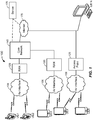
- FIG. 1 illustrates a high-level system architecture of a wireless communications system 100 in accordance with an embodiment of the invention.
- the wireless communications system 100 contains UEs 1...N.
- the UEs 1...N can include cellular telephones, personal digital assistant (PDAs), pagers, a laptop computer, a desktop computer, and equivalents thereof.
- PDAs personal digital assistant
- UEs 1...2 are illustrated as cellular calling phones
- UEs 3...5 are illustrated as cellular touchscreen phones or smart phones
- UE N is illustrated as a desktop computer or PC.
- UEs 1...N are configured to communicate with an access network (e.g., the RAN 120, an access point 125, etc.) over a physical communications interface or layer, shown in FIG. 1 as air interfaces 104, 106, 108 and/or a direct wired connection.
- the air interfaces 104 and 106 can comply with a given cellular communications protocol (e.g., CDMA, EVDO, eHRPD, GSM, EDGE, W-CDMA, LTE, etc.), while the air interface 108 can comply with a wireless IP protocol (e.g., IEEE 802.11).
- the RAN 120 includes a plurality of access points that serve UEs over air interfaces, such as the air interfaces 104 and 106.
- the access points in the RAN 120 can be referred to as access nodes or ANs, access points or APs, base stations or BSs, Node Bs, eNode Bs, and equivalents thereof. These access points can be terrestrial access points (or ground stations), or satellite access points.
- the RAN 120 is configured to connect to a core network 140 that can perform a variety of functions, including bridging circuit switched (CS) calls between UEs served by the RAN 120 and other UEs served by the RAN 120 or a different RAN altogether, and can also mediate an exchange of packet-switched (PS) data with external networks such as Internet 175.
- the Internet 175 includes a number of routing agents and processing agents (not shown in FIG. 1 for the sake of convenience). In FIG.
- UE N is shown as connecting to the Internet 175 directly (i.e., separate from the core network 140, such as over an Ethernet connection of WiFi or 802.11-based network).
- the Internet 175 can thereby function to bridge packet-switched data communications between UE N and UEs 1...N via the core network 140.
- the access point 125 is also shown in FIG. 1 .
- the access point 125 may be connected to the Internet 175 independent of the core network 140 (e.g., via an optical communication system such as FiOS, a cable modem, etc.).
- the air interface 108 may serve UE 4 or UE 5 over a local wireless connection, such as IEEE 802.11 in an example.
- UE N is shown as a desktop computer with a wired connection to the Internet 175, such as a direct connection to a modem or router, which can correspond to the access point 125 itself in an example (e.g., for a WiFi router with both wired and wireless connectivity).
- a modem or router which can correspond to the access point 125 itself in an example (e.g., for a WiFi router with both wired and wireless connectivity).
- a server 170 is shown as connected to the Internet 175, the core network 140, or both.
- the server 170 can be implemented as a plurality of structurally separate servers, or alternately may correspond to a single server.
- the server 170 is configured to support one or more communication services (e.g., Voice-over-Internet Protocol (VoIP) sessions, Push-to-Talk (PTT) sessions, group communication sessions, social networking services, etc.) for UEs that can connect to the server 170 via the core network 140 and/or the Internet 175, and/or to provide content (e.g., web page downloads) to the UEs.
- VoIP Voice-over-Internet Protocol
- PTT Push-to-Talk
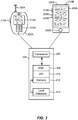
- FIG. 2 illustrates examples of UEs (i.e., client devices) in accordance with embodiments of the invention.
- UE 200A is illustrated as a calling telephone and UE 200B is illustrated as a touchscreen device (e.g., a smart phone, a tablet computer, etc.).
- an external casing of UE 200A is configured with an antenna 205A, display 210A, at least one button 215A (e.g., a PTT button, a power button, a volume control button, etc.) and a keypad 220A among other components, as is known in the art.
- button 215A e.g., a PTT button, a power button, a volume control button, etc.
- an external casing of UE 200B is configured with a touchscreen display 205B, peripheral buttons 210B, 215B, 220B and 225B (e.g., a power control button, a volume or vibrate control button, an airplane mode toggle button, etc.), at least one front-panel button 230B (e.g., a Home button, etc.), among other components, as is known in the art.
- peripheral buttons 210B, 215B, 220B and 225B e.g., a power control button, a volume or vibrate control button, an airplane mode toggle button, etc.
- at least one front-panel button 230B e.g., a Home button, etc.
- the UE 200B can include one or more external antennas and/or one or more integrated antennas that are built into the external casing of UE 200B, including but not limited to WiFi antennas, cellular antennas, satellite position system (SPS) antennas (e.g., global positioning system (GPS) antennas), and equivalents thereof.
- WiFi antennas e.g., WiFi
- cellular antennas e.g., cellular antennas
- satellite position system (SPS) antennas e.g., global positioning system (GPS) antennas
- GPS global positioning system
- the platform 202 can receive and execute software applications, data, and/or commands transmitted from the RAN 120 that may ultimately come from the core network 140, the Internet 175 and/or other remote servers and networks (e.g., application server 170, web URLs, etc.).
- the platform 202 can also independently execute locally stored applications without RAN interaction.
- the platform 202 can include a transceiver 206 operably coupled to an application specific integrated circuit (ASIC) 208, or other processor, microprocessor, logic circuit, or other data processing device.
- ASIC application specific integrated circuit
- the ASIC 208 executes the application programming interface (API) layer 210 that interfaces with any resident programs in the memory 212 of the UEs 200A and 200B.
- the memory 212 can be comprised of read-only or random-access memory (RAM and ROM), EEPROM, flash cards, or any memory common to computer platforms.
- the platform 202 also can include a local database 214 that can store applications not actively used in memory 212, as well as other data.
- the local database 214 is typically a flash memory cell, but can be any secondary storage device as known in the art, such as magnetic media, EEPROM, optical media, tape, soft or hard disk, or the like.
- an embodiment of the invention can include a UE (e.g., UE 200A, 200B, etc.) including the ability to perform the functions described herein.
- a UE e.g., UE 200A, 200B, etc.
- the various logic elements can be embodied in discrete elements, software modules executed on a processor or any combination of software and hardware to achieve the functionality disclosed herein.
- the ASIC 208, memory 212, API layer 210 and local database 214 may all be used cooperatively to load, store and execute the various functions disclosed herein and thus the logic to perform these functions may be distributed over various elements.
- the functionality could be incorporated into one discrete component. Therefore, the features of the UEs 200A and 200B in FIG. 2 are to be considered merely illustrative and the invention is not limited to the illustrated features or arrangement.
- the wireless communication between the UEs 200A and/or 200B and the RAN 120 can be based on different technologies, such as CDMA, W-CDMA, time division multiple access (TDMA), frequency division multiple access (FDMA), Orthogonal Frequency Division Multiplexing (OFDM), GSM, or other protocols that may be used in a wireless communications network or a data communications network.
- CDMA Code Division Multiple Access
- W-CDMA time division multiple access
- FDMA frequency division multiple access
- OFDM Orthogonal Frequency Division Multiplexing
- GSM Global System for Mobile communications
- voice transmission and/or data can be transmitted to the UEs from the RAN using a variety of networks and configurations. Accordingly, the illustrations provided herein are not intended to limit the embodiments of the invention and are merely to aid in the description of aspects of embodiments of the invention.
- FIG. 3 illustrates a communication device 300 that includes logic configured to perform functionality.
- the communication device 300 can correspond to any of the above-noted communication devices, including but not limited to UEs 200A or 200B, any component of the RAN 120, any component of the core network 140, any components coupled with the core network 140, and/or the Internet 175 (e.g., the server 170), and equivalents thereof.
- the communication device 300 can correspond to any electronic device that is configured to communicate with (or facilitate communication with) one or more other entities over the wireless communications system 100 of FIG. 1 .
- the communication device 300 includes logic configured to receive and/or transmit information 305.
- the communication device 300 corresponds to a wireless communications device (e.g., UE 200A or 200B, access point 125, a BS, Node B or eNodeB in the RAN 120, etc.)
- the logic configured to receive and/or transmit information 305 can include a wireless communications interface (e.g., Bluetooth, WiFi, 2G, CDMA, W-CDMA, 3G, 4G, LTE, etc.) such as a wireless transceiver and associated hardware (e.g., an RF antenna, a MODEM, a modulator and/or demodulator, etc.).
- a wireless communications interface e.g., Bluetooth, WiFi, 2G, CDMA, W-CDMA, 3G, 4G, LTE, etc.
- a wireless transceiver and associated hardware e.g., an RF antenna, a MODEM, a modulator and/or demodulator, etc.
- the logic configured to receive and/or transmit information 305 can correspond to a wired communications interface (e.g., a serial connection, a USB or Firewire connection, an Ethernet connection through which the Internet 175 can be accessed, etc.).
- a wired communications interface e.g., a serial connection, a USB or Firewire connection, an Ethernet connection through which the Internet 175 can be accessed, etc.
- the communication device 300 corresponds to some type of network-based server (e.g., server 170, etc.)
- the logic configured to receive and/or transmit information 305 can correspond to an Ethernet card, in an example, that connects the network-based server to other communication entities via an Ethernet protocol.
- the logic configured to receive and/or transmit information 305 can include sensory or measurement hardware by which the communication device 300 can monitor its local environment (e.g., an accelerometer, a temperature sensor, a light sensor, an antenna for monitoring local RF signals, etc.).
- the logic configured to receive and/or transmit information 305 can also include software that, when executed, permits the associated hardware of the logic configured to receive and/or transmit information 305 to perform its reception and/or transmission function(s).
- the logic configured to receive and/or transmit information 305 does not correspond to software alone, and the logic configured to receive and/or transmit information 305 relies at least in part upon hardware to achieve its functionality.
- the communication device 300 further includes logic configured to process information 310.
- the logic configured to process information 310 can include at least a processor.
- Example implementations of the types of processing that can be performed by the logic configured to process information 310 include, but is not limited to, performing determinations, establishing connections, making selections between different information options, performing evaluations related to data, interacting with sensors coupled to the communication device 300 to perform measurement operations, converting information from one format to another (e.g., between different protocols such as .wmv to .avi, etc.), and equivalents thereof.
- the processor included in the logic configured to process information 310 can correspond to a general purpose processor, a digital signal processor (DSP), an ASIC, a field programmable gate array (FPGA) or other programmable logic device, discrete gate or transistor logic, discrete hardware components, or any combination thereof designed to perform the functions described herein.
- a general purpose processor may be a microprocessor, but in the alternative, the processor may be any conventional processor, controller, microcontroller, or state machine.
- a processor may also be implemented as a combination of computing devices, e.g., a combination of a DSP and a microprocessor, a plurality of microprocessors, one or more microprocessors in conjunction with a DSP core, or any other such configuration.
- the logic configured to process information 310 can also include software that, when executed, permits the associated hardware of the logic configured to process information 310 to perform its processing function(s). However, the logic configured to process information 310 does not correspond to software alone, and the logic configured to process information 310 relies at least in part upon hardware to achieve its functionality.
- the communication device 300 further includes logic configured to store information 315.
- the logic configured to store information 315 can include at least a non-transitory memory and associated hardware (e.g., a memory controller, etc.).
- the non-transitory memory included in the logic configured to store information 315 can correspond to RAM memory, flash memory, ROM memory, EPROM memory, EEPROM memory, registers, hard disk, a removable disk, a CD-ROM, or any other form of storage medium known in the art.
- the logic configured to store information 315 can also include software that, when executed, permits the associated hardware of the logic configured to store information 315 to perform its storage function(s). However, the logic configured to store information 315 does not correspond to software alone, and the logic configured to store information 315 relies at least in part upon hardware to achieve its functionality.
- the communication device 300 further optionally includes logic configured to present information 320.
- the logic configured to present information 320 can include at least an output device and associated hardware.
- the output device can include a video output device (e.g., a display screen, a port that can carry video information such as USB, HDMI, etc.), an audio output device (e.g., speakers, a port that can carry audio information such as a microphone jack, USB, HDMI, etc.), a vibration device and/or any other device by which information can be formatted for output or actually outputted by a user or operator of the communication device 300.
- a video output device e.g., a display screen, a port that can carry video information such as USB, HDMI, etc.
- an audio output device e.g., speakers, a port that can carry audio information such as a microphone jack, USB, HDMI, etc.
- a vibration device e.g., a vibration device by which information can be formatted for output or actually outputted by a user or operator of the
- the logic configured to present information 320 can include the display 210A of UE 200A or the touchscreen display 205B of UE 200B.
- the logic configured to present information 320 can be omitted for certain communication devices, such as network communication devices that do not have a local user (e.g., network switches or routers, remote servers such as the server 170, etc.).
- the logic configured to present information 320 can also include software that, when executed, permits the associated hardware of the logic configured to present information 320 to perform its presentation function(s).
- the logic configured to present information 320 does not correspond to software alone, and the logic configured to present information 320 relies at least in part upon hardware to achieve its functionality.
- the communication device 300 further optionally includes logic configured to receive local user input 325.
- the logic configured to receive local user input 325 can include at least a user input device and associated hardware.
- the user input device can include buttons, a touchscreen display, a keyboard, a camera, an audio input device (e.g., a microphone or a port that can carry audio information such as a microphone jack, etc.), and/or any other device by which information can be received from a user or operator of the communication device 300.
- the communication device 300 corresponds to UE 200A or UE 200B as shown in FIG.
- the logic configured to receive local user input 325 can include the keypad 220A, any of the buttons 215A or 210B through 225B, the touchscreen display 205B, etc.
- the logic configured to receive local user input 325 can be omitted for certain communication devices, such as network communication devices that do not have a local user (e.g., network switches or routers, remote servers such as the server 170, etc.).
- the logic configured to receive local user input 325 can also include software that, when executed, permits the associated hardware of the logic configured to receive local user input 325 to perform its input reception function(s). However, the logic configured to receive local user input 325 does not correspond to software alone, and the logic configured to receive local user input 325 relies at least in part upon hardware to achieve its functionality.
- any software used to facilitate the functionality of the configured logics of 305 through 325 can be stored in the non-transitory memory associated with the logic configured to store information 315, such that the configured logics of 305 through 325 each performs their functionality (i.e., in this case, software execution) based in part upon the operation of software stored by the logic configured to store information 315.
- hardware that is directly associated with one of the configured logics can be borrowed or used by other configured logics from time to time.
- the processor of the logic configured to process information 310 can format data into an appropriate format before being transmitted by the logic configured to receive and/or transmit information 305, such that the logic configured to receive and/or transmit information 305 performs its functionality (i.e., in this case, transmission of data) based in part upon the operation of hardware (i.e., the processor) associated with the logic configured to process information 310.
- logic configured to as used throughout this disclosure is intended to invoke an embodiment that is at least partially implemented with hardware, and is not intended to map to software-only implementations that are independent of hardware.
- the configured logic or “logic configured to” in the various blocks are not limited to specific logic gates or elements, but generally refer to the ability to perform the functionality described herein (either via hardware or a combination of hardware and software).
- the configured logics or “logic configured to” as illustrated in the various blocks are not necessarily implemented as logic gates or logic elements despite sharing the word “logic.” Other interactions or cooperation between the logic in the various blocks will become clear to one of ordinary skill in the art from a review of the embodiments described below in more detail.
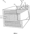
- the server 400 may correspond to one example configuration of the server 170 described above.
- the server 400 includes a processor 401 coupled to volatile memory 402 and a large capacity nonvolatile memory, such as a disk drive 403.
- the server 400 may also include a floppy disc drive, compact disc (CD) or DVD disc drive 406 coupled to the processor 401.
- the server 400 may also include network access ports 404 coupled to the processor 401 for establishing data connections with a network 407, such as a local area network coupled to other broadcast system computers and servers or to the Internet.
- a network 407 such as a local area network coupled to other broadcast system computers and servers or to the Internet.
- FIG. 4 illustrates one example implementation of the communication device 300, whereby the logic configured to receive and/or transmit information 305 corresponds to the network access ports 404 used by the server 400 to communicate with the network 407, the logic configured to process information 310 corresponds to the processor 401, and the logic configuration to store information 315 corresponds to any combination of the volatile memory 402, the disk drive 403 and/or the disc drive 406.
- the optional logic configured to present information 320 and the optional logic configured to receive local user input 325 are not shown explicitly in FIG. 4 and may or may not be included therein.
- FIG. 4 helps to demonstrate that the communication device 300 may be implemented as a server, in addition to a UE implementation as in 200A or 200B as in FIG. 2 .
- a conventional shared media playlist permits a first user to obtain access to media associated with a second user.
- the first user can decide which media to access by browsing the second user's media, searching the second user's media, or accepting the second user's recommendation. Once the first user selects media associated with the second user, the first user can be added to the shared media playlist, and accessed by the first user.
- the multiple users can independently add media to the shared media playlist.
- the media can be associated with any one of the multiple users.
- the shared media playlist can be accessed on a user device associated with any one of the multiple users.
- a media server can be utilized to re-order the playlist based on shared preferences of the multiple users.
- the shared media playlist is associated with a shared media output device.
- the shared media playlist can be accessed on the shared media output device.
- a plurality of users associated with the shared media playlist can simultaneously access the media presented on the shared media playlist.
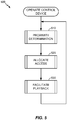
- FIG. 5 generally illustrates a high-level method 500 of operating a control device in accordance with an embodiment of the invention.
- the control device determines how many UEs are in a proximity zone and attempts to identify the UEs that are in the proximity zone.
- the control device receives or obtains UE data concerning at least one specific UE, for example, UE 200A, UE 200B, or the like. Based on the UE data, the control device may allocate, to the at least one specific UE, access to a shared media output device.
- the control device facilitates playback of specific media content (e.g., audio and/or video) on behalf of the at least one specific UE in accordance with the access allocation of 520.
- specific media content e.g., audio and/or video
- control device can correspond to the shared media output device, one of the proximate UEs, a remote server or a remote UE. Accordingly, if the control device is the shared media output device, the playback can be facilitated by directly playing the media content on behalf of the at least one specific UE. In another example, if the control device is the proximate UE, remote server, or remote UE, the playback can be facilitated by streaming the media content to the shared media output device for playback, directing some other device to stream the media content to the shared media output device for playback or signaling the shared media output device that playback for the media content is permitted whereby the shared media output device is relied upon to acquire the media content on its own.
- FIG. 6 generally illustrates a system 600 comprising a control device 610 similar to communication device 300, server 400, or the like.
- the control device 610 may be configured to track UE data, which may be used to allocate access by associated UEs to the shared media output device.
- the UE data may be stored in a UE data table 620.
- the control device 610 may also be configured to assign different UE priority statuses to a plurality of different UEs so that access can be conveniently allocated.
- the different UE priority statuses may be determined by a UE priority determination device 630.
- the control device 610 may also be configured to track data relating to media content (hereinafter "MC data") which may be used to facilitate playback of the MC data.
- MC data data relating to media content
- the MC data may be stored in a MC data table 640.
- the control device 610 may also be configured to assign different MC priority statuses to different media content so as to facilitate prioritized playback of the MC data.
- the MC priority status of a given unit of MC data may be determined by a MC priority determination device 650.
- the system 600 may further comprise a shared media output device (“SMOD”) 660 and a proximity determination device (“PDD”) 670.
- the SMOD 660 is associated with a media coverage zone 661, which is defined as an area in which persons are expected to be able to be in range of the media content output by the SMOD 660 (e.g., for a video presentation, the media coverage zone 661 can correspond to area in which a screen of the SMOD 660 can be viewed, for an audio presentation, the media coverage zone 661 can be an area in which audio is expected to be received at a given decibel level, and equivalents thereof).
- the PDD 670 is likewise associated with a proximity zone 671, which is defined as an area in which the presence of one or more UEs 680-1, 680-2... 680-N (referred to generally as UEs 680) can be identified (e.g., whereby N is an integer greater than or equal to 3).
- UEs 680 UEs 680
- FIG. 6 the media coverage zone 661 partially overlaps the proximity zone 671, it will be understood that the media coverage zone 661 may wholly subsume the proximity zone 671, or vice-versa.
- the control device 610 facilitates playback of media content on the SMOD 660.
- the media content is delivered to the shared media output device by one or more of downloading requested media content from the first user equipment, downloading the requested media content from a cloud content service, streaming the requested media content from the first user equipment, or streaming the requested media content from a cloud content service.
- the PDD 670 may obtain and process UE data and/or MC data and relay it to the control device 610.
- the UE data and/or MC data may be obtained from one or more of the UEs 680.
- the UEs 680 may be similar to UE 200A, UE 200B, or the like.
- control device 610 can optionally be connected to the Internet 175, from which media content, UE data and/or MC data may be obtained and or used to deliver the MC data to the SMOD 660.
- control device 610 may be a device that locally controls the SMOD 660 or can even correspond to the SMOD 660 itself, in which case the Internet 175 connection is not strictly necessary, although still possible for the purpose of acquiring media content, MC data and/or UE data, and equivalents thereof.
- FIG. 6 illustrates control device 610, UE data table 620, UE priority determination device 630, MC data table 640, MC priority determination device 650, SMOD 660, PDD 670, and UEs 680-1, 680-2... 680-N as distinct elements, it will be understood that any subset of these elements can be combined into a single device.
- the elements that make up system 600 may be combined into one or more devices similar to the communication device 300, server 400, or the like.
- the elements that make up system 600 may also be divided into sub-elements similar to the communication device 300, server 400, or the like.
- control device 610 may communicate with one another in accordance with any known communication protocol.
- UE data table 620 may communicate with one another in accordance with any known communication protocol.
- MC data table 640 may communicate with one another in accordance with any known communication protocol.
- SMOD 660 may communicate with one another in accordance with any known communication protocol.
- PDD 670 may communicate with one another in accordance with any known communication protocol.
- UEs 680-1, 680-2... 680-N may communicate with one another in accordance with any known communication protocol.
- each of the above elements is provided on one of the individual UEs 680.
- the individual UEs 680-1, 680-2... 680-N are distinct elements, but the remainder of the elements are provided on the control device 610 (e.g., the PDD 670 and/or the control device 610 are implemented within the SMOD 660, etc.).
- the control device 610, UE data table 620, UE priority determination device 630, MC data table 640, and MC priority determination device 650 are provided remotely while the SMOD 660 and PDD 670 are provided locally as a single device.
- the SMOD 660 and PDD 670 are provided locally as a single device having a docking station (not shown) for receiving at least one individual UE such as UE 680-1, and the control device 610, UE data table 620, UE priority determination device 630, MC data table 640, and MC priority determination device 650 are provided on UE 680-1, and equivalents thereof.
- the system 600 may be implemented as software application that is present on a number of devices, any of which may act as, for example, the control device 610, SMOD 660, or PDD 670. Additionally, the software application implementation of system 600 may be embedded as a software development kit (SDK) into a pre-existing audio software application.
- SDK software development kit
- a UE data table 700 is used to track UE identification numbers ("UE IDs") 1... N (e.g., whereby N is an integer greater than or equal to 3).
- the UE IDs may be referred to individually as UE ID 701-1, UE ID 701-2, UE ID 701-N, etc., or generally as UE IDs 701. Creation and modification of the UE data table 700 may be facilitated by a control device such as, for example, control device 610.
- Each UE ID 701 may be associated with a unique UE.
- Each UE ID 701 is associated with UE identification data 705 as well an activation status 702, a UE priority status 703, and/or a proximity status 704.
- the activation status 702 may be a simple binary indication of an active status 702a or an inactive status 702b.
- the UE priority status 703 may contain a hierarchy including, for example, a high-priority UE status 703a and a low-priority UE status 703b. Any number of intermediate-priority UE statuses 703c are also possible, and in some aspects the UE priority status 703 may include a weighting factor or coefficient that fits within a wide range of potential priority statuses.
- the proximity status 704 may be a simple binary determination such as, for example, a present status 704a or an absent status 704b. Other proximity statuses are also possible, such as for example, a temporarily absent status 704c.
- the UE data table 700 may store UE identification data 705 that enables the control device 610 to identify an association between a proximate UE and a unique UE ID 701-1.
- the UE identification data 705 may comprise any identifying UE-specific information.
- the UE identification data 705 can include an account number, subscriber identifier, a user identity, an online user identity, an online user account, etc., from which the control device 610 can verify the media content to which the respective proximate UE is permitted access.
- the control device 610 may obtain the UE identification data 705 using any of a variety of methods.
- the control device 610 receives an identifying signal transmitted from a UE 680-1, which is subsequently processed and provided to the UE data table 700 as UE identification data 705-1. Additionally or alternatively, the control device 610 may transmit a signal to a UE 680-1 which prompts the UE 680-1 to send an identifying signal (which is likewise processed and provided to the UE data table 700 as UE identification data 705). In either case, the signals may be transmitted directly, via a network, a social network, a subscription service, or the Internet. If UE identification data 705 is stored locally, the control device 610 may obtain the UE identification data 705 from local storage. If UE identification data 705 is available elsewhere, the control device 610 may obtain the UE identification data 705 from a network, a social network, a subscription service, or the Internet.
- an application module and/or data associated with an application module is stored on a UE 680-1.
- the application may be, for example, a streaming content service.
- the UE 680-1 may transmit UE identification data 705 to the control device 610 that indicates a unique subscriber identifier for the streaming content service.
- the control device 610 is enabled to access the streaming content service associated with the unique subscriber identifier.
- any data which enables control device 610 to access the streaming content service associated with the unique subscriber identifier may be stored as UE identification data 705.
- UE identification data 705 may also include any data which enables control device 610 to identify UE 680-1 and/or associate the streaming content, streaming content service, and/or unique subscriber identifier with UE 680-1. While the UE IDs 701 are illustrated in FIG. 7 as being separate from the UE identification data 705, in another embodiment a single unified UE ID data field can be implemented.
- the unified UE ID data field can correspond to a list of MAC addresses of each proximate UE from which the media content permissions of each proximate UE can be looked up.
- the UE data table 700 may be automatically updated on an intermittent basis. Additionally or alternatively, the UE data table 700, or any portion thereof, may be updated in an event-triggered manner, such as whenever a change is detected in the activation status 702, UE priority status 703, proximity status 704, or UE identification data 705. Additionally or alternatively, the UE data table 700 may be accessed and modified manually, for example, updated by an administrator.
- a resident of a home who is planning a party can create a list of potential guests using, for example, the control device 610.
- the potential guest or list of potential guests may be input manually by an administrator; derived from a network, a social network, a subscription service, or the Internet; and/or copied from a previously-submitted list of potential guests.
- the potential guests may of their own volition add other potential guests. If UE identification data 705 is already stored in the UE data table 700, then each potential guest added to the list may already be associated with one or more UE IDs 701.
- the control device 610 may be configured to verify or update UE identification data 705 via a network, a social network, a subscription service, or the Internet. If UE identification data 705 is not already stored in the UE data table 700, the control device 610 may be configured to obtain the UE identification data 705 in any of the ways set forth in the present disclosure.
- an activation status 702 for each associated UE ID 701 may be manually set by the administrator, or automatically set to a default status.
- the default status may be, for example, an active status 702a or an inactive status 702b.
- every UE ID 701 is initially set to an inactive status 702b.
- a trigger may shift the activation status 702 associated with any given UE ID 701 into an active status 702a.
- an administrator submits a list of three potential guests.
- the control device 610 creates a unique UE ID 701 for each potential guest ("1", “2", and “3” respectively) in the UE data table 700.
- the control device 610 sets the activation status 702 for each UE ID to an inactive status 702b ("INACTIVE"), which, according to this example, is a default setting.
- the control device 610 also stores UE identification data 705 ("XXXX[1]”, “XXXX[2]”, and "XXXX[3]", respectively) which is useful for associating the newly created UE IDs "1", "2", and "3" with a respective UE, a UE identification signal, a UE communication protocol, a user identity, an online user identity, or an online user account, and relatedly, the MC data to which each respective UE is permitted access: Table 1 UE ID Activation Status UE Priority Status Proximity Status UE Identification Data 1 INACTIVE N/A N/A XXXX[1] 2 INACTIVE N/A N/A XXX[2] 3 INACTIVE N/A N/A XXXX[3]
- control device 610 is further configured to send electronic invitations to each of the guests.
- the invitations may be sent directly to the UEs 680 associated with each of the respective guests, or sent to the guests via a network, a social network, a subscription service, or the Internet.
- the control device 610 receives an acceptance of the invitation, or RSVP, the UE ID 701 associated with an invited guest may be shifted from an inactive status 702b to an active status 702a.
- Table 2 reflects a scenario where the guests associated with UE IDs "1" and "3" have accepted the invitation.
- the respective activation statuses 702 for each of UE ID "1" and "3” have accordingly been shifted to "ACTIVE".
- the invitations sent by the control device 610 include a request for additional UE identification data 705, for example, data that will enable the control device 610 to specifically recognize the guest's UE when the guest's UE enters the proximity zone 671.
- UE identification data 705 can include device-identifying information (e.g., a UE-specific SSID, a MAC address associated with the guest's UE, etc.). Further, the UE identification data 705 is not necessarily limited to device-identifying hardware parameters such as an SSID or MAC address, but could also encompass information that identifies application-layer information associated with the UE.
- a middleware layer of a software framework can broadcast application-layer information such as a multicast DNS advertisement, which can be used as part of the UE identification data 705.
- the guest associated with UE ID "3" provides such data, and UE identification data "XXXX[3]" is updated accordingly.
- the PDD 670 will recognize that a UE 680 is present, and the control device 610 will be able to specifically recognize that newly-arrived UE 680 is associated with UE ID "3".
- the invitation will additionally or alternatively include instructions that will enable the guest's UE to self-identify upon entry into the proximity zone 671 (e.g., by broadcasting a UE-identifying SSID beacon, etc.).
- a shift to active status 702a may be contingent upon a shift in the proximity status 704 of the associated UE ID 701, for example, from an absent status 704b to a present status 704a.
- the control device 610 may receive a signal from a UE 680 associated with a given UE ID 701 in which the UE 680 requests a shift to active status 702a.
- the control device 610 may also send a signal to the UE 680 prompting the user to make such a request.
- the control device 610 may automatically grant a request to shift into active status 702a, or may prompt an administrator to grant such a request.
- a UE priority status 703 for each UE ID 701 may be manually set by an administrator, or automatically set to a default status, for example, a high-priority UE status 703a or a low-priority UE status 703b.
- the UE priority status 703 can be derived from a network, a social network, a subscription service, or the Internet, and/or copied from a previously-input list of potential guests. Any number of intermediate-priority UE statuses 703c are also possible, and in some aspects the UE priority status 703 may include of a weighting factor or coefficient that fits within a wide range of potential priority statuses.
- an administrator may set a UE priority status 703 associated with his or her personal UE ID 701 to be a high-priority UE status 703a.
- a UE priority status 703 may be set or modified by a UE priority determination device such as, for example, UE priority determination device 630.
- Table 3 reflects a scenario where the control device 610 has set a UE priority status 703 for each UE ID to a low-priority UE status 703b, which is a default setting.
- a proximity determination device such as, for example, PDD 670 may detect their respective arrivals in accordance with one or more of the methods set forth in this application.
- the guest associated with UE ID "3" has already provided data that enables control device 610 to specifically recognize the guest's UE 680 when the guest's UE 680 enters the proximity zone 671(in an above-mentioned scenario, such data was requested in the guest's invitation).
- the control device 610 updated the UE identification data 705 associated with the guest's UE ID 701.
- Table 4 the updated UE identification data 705-3 is shown as "XXXX[3] ⁇ ", where the " ⁇ " symbol represents updated data.
- Table 4 reflects a scenario where control device 610 uses updated UE identification data "XXXX[3] ⁇ " to determine that the UE 680 detected by the PDD 670 is associated with preexisting UE ID 3. The control device 610 accordingly shifts the proximity status 704 associated with UE ID 3 to a present status 704a.
- Table 4 UE ID Activation Status UE Priority Status Proximity Status UE Identification Data 1 ACTIVE LOW N/A XXXX[1] 2 INACTIVE LOW N/A XXXX[2] 3 ACTIVE LOW PRESENT XXXX[3] ⁇
- the PDD 670 recognizes that a UE 680 is present, but cannot ascertain a matching UE ID 701 associated with the UE because sufficient UE identification data 705 is absent from the UE data table 700.
- the control device 610 will attempt to obtain updated UE identification data 705 in accordance with one or more of the methods identified in the present disclosure and repeat the process of ascertaining a UE ID 701 that is associated with the detected UE 680.
- Table 5 reflects a scenario where PDD 670 recognizes the presence of an unidentified UE 680, and control device 610 obtains updated UE identification data 705 from the unidentified UE 680 itself, or from some other source.
- the updated UE identification data 705 indicates that the newly-detected UE 680 is associated with preexisting UE ID "1". As shown in Table 5, the control device 610 accordingly stores the UE identification data 705 (represented as "XXXX[1] ⁇ ") and shifts the proximity status 704 associated with UE ID "1" to a present status 704a.
- Table 5 UE ID Activation Status UE Priority Status Proximity Status UE Identification Data 1 ACTIVE LOW PRESENT XXXX[1] ⁇ 2 INACTIVE LOW N/A N/A 3 ACTIVE LOW PRESENT XXXX[3] ⁇
- the PDD 670 once again recognizes that a UE 680 is present, but cannot ascertain a matching UE ID 701 associated with the UE because sufficient UE identification data 705 is absent from the UE data table 700.
- the control device 610 will attempt to obtain updated UE identification data 705 in accordance with one or more of the methods identified in the present disclosure and repeat the process of ascertaining a matching UE ID 701.
- Table 6 reflects a scenario where the PDD 670 recognizes the presence of an unidentified UE 680, and control device 610 obtains UE identification data 705 from the unidentified UE 680 itself, or from some other source.
- the UE identification data 705 indicates that the newly-detected UE 680 is not associated with any preexisting UE ID 701. Therefore, control device 610 arbitrarily assigns a new UE ID 701 to the newly-detected UE and adds a new UE ID, for example, "4", to the UE data table 700.
- the control device 610 also creates and/or stores new UE identification data 705 (represented as "XXXX[4] ⁇ ") that will enable the control device 610 to recognize the association between the newly-detected UE 680 and UE ID "4" in the future.
- the control device 610 shifts the proximity status 704 associated with UE ID "4" to a present status 704a.
- Control device 610 also assigns a default activation status 702 and UE priority status 703, in this example, "INACTIVE” and "LOW", respectively.
- Table 6 UE ID Activation Status UE Priority Status Proximity Status UE Identification Data 1 ACTIVE LOW PRESENT XXXX[1] ⁇ 2 INACTIVE LOW N/A N/A 3 ACTIVE LOW PRESENT XXXX[3] ⁇ 4 INACTIVE LOW PRESENT XXX[4] ⁇
- a UE 680 associated with newly-added UE ID "4" belongs to an 'uninvited guest'.
- a newly-detected UE 680 associated with an 'uninvited guest' may be, by default, shifted to an active status 702a by the control device 610.
- the default activation status 702 is an inactive status 702b.
- the control device 610 may be further configured to determine whether it is necessary to update the activation status 702 associated with UE ID "4".
- the control device 610 validates the UE 680 associated with UE ID "4". Validation may entail prompting the user of the UE 680 associated with UE ID "4" to enter a password via the UE 680 or the control device 610, and/or prompting an administrator to manually update the UE data table 700.
- Table 7 reflects a scenario where an administrator validates the newly-detected UE 680 associated with UE ID "4", thereby assigning an "ACTIVE" status.
- the administrator recognizes that the uninvited guest is a person of high-priority, for example, a popular local DJ or VIP, and accordingly instructs control device 610 to shift the UE priority status 703 associated with UE ID "4" to a high-priority UE status 703a.
- Table 7 UE ID Activation Status UE Priority Status Proximity Status UE Identification Data 1 ACTIVE LOW PRESENT XXXX[1] ⁇ 2 INACTIVE LOW N/A N/A 3 ACTIVE LOW PRESENT XXX[3] ⁇ 4 ACTIVE HIGH PRESENT XXX[4] ⁇
- Table 7 reflects a scenario in which the activation status 702 and UE priority status 703 are shifted simultaneously by an administrator, it should be understood that activation status 702 and UE priority status 703 are wholly independent variables and may be shifted in accordance with any method set forth in the present disclosure.
- the UE priority status 703 may be created or modified by a UE priority determination device such as, for example, the UE priority determination device 630.
- the PDD 670 may detect their respective departures in accordance with one or more of the methods set forth in this application.
- the control device 610 recognizes that the UE associated with UE ID "3" is no longer present and shifts the associated proximity status 704 to an absent status 704b.
- the control device 610 recognizes that the UE 680 associated with UE ID "3" is no longer present and shifts the associated proximity status 704 to a temporarily absent status 704c.
- Table 8 UE ID Activation Status UE Priority Status Proximity Status UE Identification Data 1 ACTIVE LOW PRESENT XXXX[1] 2 INACTIVE LOW N/A N/A 3 ACTIVE LOW TEMP. XXXX[3] 4 ACTIVE HIGH PRESENT XXXX[4]
- Table 9 reflects this scenario.
- Table 9 UE ID Activation Status UE Priority Status Proximity Status UE Identification Data 1 ACTIVE LOW PRESENT XXXX[1] 2 INACTIVE LOW N/A N/A 3 ACTIVE LOW ABSENT XXXX[3] 4 ACTIVE HIGH PRESENT XXXX[4]
- the period of time in which a temporarily absent status 704c prevails may be derived from a default setting of the control device 610, manually input by the administrator of the control device 610, or set to be dynamic in accordance with any number of factors, including a total number of UE IDs 701, a total number of UE IDs 701 in an active status 702a, and/or a total number of UE IDs 701 in a present status 704a.
- the period of time may also be linked to any variable in a MC data table 800, described below, or any activity performed by the SMOD 660, for example, a number of units of media content played back. If a UE 680 associated with a temporarily absent status 704c re-enters the proximity zone 671, the proximity status 704 associated with the UE 680 may be shifted back to a present status 704a.
- the MC data table 800 may be used to track MC identification numbers ("MC IDs") 1...N (e.g., where N is an integer that is greater than or equal to 3), 801. Creation and modification of the MC data table 800 may be facilitated by a control device such as, for example, control device 610.
- Each MC ID 801 may be associated with a unique unit of media content.
- Each MC ID 801-1, 801-2... 801-N may further be associated with MC identification data 802 (for example, 802-1, 802-2... 802-N), MC/UE association data 803 (for example, 803-1, 803-2... 803-N), as well as data on a digital rights management (“DRM”) status 804 and a MC priority status 805.
- DRM digital rights management
- the DRM status 804 may be a simple binary indication of an authenticated status 804a or a blocked status 804b.
- the control device 610 may ensure that playback of media content on the SMOD 660 is facilitated only if the media content's unique MC ID 801 is associated with an authenticated status 804a.
- the MC data table 800 may store MC identification data 802 that enables the control device 610 to link extant media content to a unique MC ID 801.
- the MC identification data 802 comprises any information that enables the control device 610 to identify an association between two or more of the MC ID 801, a specific unit of media content, a link to a specific unit of media content or media content stream, or a specific media content tag or identifier.
- the control device 610 may obtain the MC identification data 802 directly from a specific unit of media content. If the MC identification data 802 is stored locally, the control device 610 may obtain the MC identification data 802 from local storage. If the MC identification data 802 is available elsewhere, the control device 610 may obtain the data from a network, a social network, a subscription service, or the Internet.
- the MC data table 800 may store MC/UE association data 803 that enables the control device 610 to link a specific MC ID 801 to one or more UE IDs 701.
- the one or more UE IDs 701 identified by the MC/UE association data 803 compose a subset 701-S that includes all UE IDs 701 that have acquired, reserved, or linked to media content associated with a specific MC ID 801.
- the MC data table 800 may be automatically updated on an intermittent basis. Additionally or alternatively, the MC data table 800 or any portion thereof may be updated in an event-triggered manner, such as whenever a change is detected in the MC identification data 802, MC/UE association data 803, DRM status 804, and/or MC priority status 805. Additionally or alternatively, the MC data table 800 can be accessed and modified manually, for example, updated by an administrator.
- a resident of a home who is planning a party can submit a list of extant media content to the control device 610.
- the media content may be acquired, reserved, or linked to in accordance with any number of methods.
- an administrator manually inputs media content and/or links to media content into the control device 610; streams, records, or copies the media content from a network, a social network, subscription service and/or the Internet; bookmarks specific media content for streaming, recording, or copying via a network, social network, subscription service and/or the Internet; copies media content or links to media content from local storage; and/or bookmarks media content for playback or streaming from local storage.
- the media content may be acquired, reserved, or linked not only by an administrator, but by any UE 680-1, 680-2... 680-N associated with a unique UE ID 701.
- these methods are performed by some, but not all, UEs 680 associated with a unique UE ID 701, for example, only by UEs 680 with an active status 702a, a high-priority UE status 703a, and/or a present status 704a, or some other combination of statuses.
- the control device 610 may attempt to link the media content to a unique MC ID 801.
- the control device 610 may be configured to verify or update the MC identification data 802 via a network, a social network, a subscription service, or the Internet. If the MC identification data 802 is not already stored in the MC data table 800, the control device may be configured to obtain the MC identification data 802 in any of the ways set forth in the present disclosure.
- the MC/UE association data 803 links a specific MC ID 801-1 to one or more of the UE IDs 701.
- the one or more UE IDs 701 identified by the MC/UE association data 803 compose a subset 701-S.
- media content associated with a unique MC ID 801a is submitted to the control device 610. If the submitted media content is acquired, reserved, or linked to by an administrator, the MC/UE association data 803 may comprise data that links the unique MC ID 801a to the UE ID 701 associated with the administrator.
- the MC/UE association data 803 may comprise data that links the unique MC ID 801a to the UE ID 701 associated with UE 680-N.
- the MC/UE association data 803 may further comprise data that indicates whether the UE 680-N associated with the UE ID 701 has authority and/or authorization to play back the submitted media content. In some scenarios, authorization can only be granted by a third party, such as, for example, a copyright holder or licensee.
- the MC/UE association data 803 may further comprise data that indicates how and/or how often the authority and/or authorization are to be verified.
- the control device 610 may be configured to utilize the MC/UE association data 803 to verify that the UE 680-N has authority and/or authorization to play back the linked media content.
- control device 610 may be configured to prompt the UE 680-N to supply the MC/UE association data 803 necessary for such verification.
- the control device 610 will determine which, if any, other UEs 680 have authority and/or authorization to play back the linked media content.
- the MC/UE association data 803 may comprise data that links the MC ID 801a to a subset 701-S of UE IDs 701, all of which have authority and/or authorization to play back the linked media content.
- the control device 610 may be configured to restrict the subset 701-S to UE IDs 701 with an active status 702a, a high-priority UE status 703a, and/or a present status 704a, or some other combination of statuses.
- the MC/UE association data 803 may be automatically updated on an intermittent basis. Additionally or alternatively, the MC/UE association data 803 may be updated upon an update to UE data table 700, MC data table 800, or any component thereof.
- the DRM status 804 may, by default, be shifted to a blocked status 804b.
- the control device 610 may utilize MC/UE association data 803 to determine whether to shift from a blocked status 804b to an authenticated status 804a, or vice-versa.
- MC/UE association data 803 indicates a link between a given MC ID 801a and a subset 701-S of one or more UE IDs 701, each of which is authorized to play back the media content associated with the MC ID 801a.
- the control device 610 may look to UE data table 700 to determine if at least one UE ID 701 from the subset 701-S has a present status 704a.
- the control device 610 may shift the DRM status 804 associated with the MC ID 801a to an authenticated status 804a. If, on the other hand, each UE ID 701 in the subset 701-S is associated an absent status 704b, the control device 610 may shift the DRM status 804 associated with the MC ID 801a to a blocked status 804b.
- the DRM status 804 may be automatically updated on an intermittent basis. Additionally or alternatively, the DRM status 804 may be updated upon an update to UE data table 700, MC data table 800, or any component thereof. In one possible scenario, updating of DRM status 804 is linked to any shift in a proximity status 704 of any UE ID 701.
- a MC priority status 805 for each MC ID 801 may be manually set by an administrator, or automatically set to a default status, for example, a high-priority MC status 805a or a low-priority MC status 805b.
- MC priority status 805 can be derived from a network, a social network, a subscription service, or the Internet, and/or copied from a previously-input list of media content. Any number of intermediate-priority MC statuses 805c is also possible, and in some aspects the MC priority status 805 may include a weighting factor or coefficient that fits within a wide range of potential priority statuses.
- the MC priority status 805 may be created or modified by a MC priority determination device such as, for example, the MC priority determination device 650.
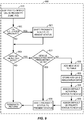
- FIG. 9 generally illustrates a method 900 of determining proximity.
- the method 900 may be an implementation of the proximity determination 510 depicted in FIG. 5 .
- the method 900 may be performed by a control device such as, for example, control device 610.
- the control device 610 utilizes a PDD, for example, the PDD 670 to determine the presence of UEs within a proximity zone, for example, proximity zone 671.
- the PDD 670 may affirmatively detect that the UE is either present in, or absent from, the proximity zone 671.
- the PDD 670 may attempt to ascertain that the UE is present in the proximity zone 671, and if the attempt fails, conclude that the UE is absent.
- the control device 610 verifies that every UE ID 701 with a present status 704a is still within the proximity zone 671. If all UE IDs 701 having a present status 704a are determined to be within the proximity zone 671, then the method 900 proceeds directly to 930. Otherwise, the method 900 proceeds to 921, where the proximity status 704 of every UE 680 determined to be absent is shifted to an absent status 704b (as noted above, a temporarily absent status 704c is also possible, in which case a shift to the absent status 704b would be delayed or avoided). After 921 is complete, the method 900 proceeds to 930.
- the control device 610 determines whether the PDD 670 has detected a UE 680 within the proximity zone 671 which is not associated with a present status 704a. If not, then the method 900 terminates or (if the method 900 is an implementation of the proximity determination 510 depicted in FIG. 5 ) returns to the method 500. Otherwise, the method 900 proceeds to 931.
- the control device 610 utilizes UE identification data, for example, UE identification data 705, to determine whether the detected UE 680 is associated with a pre-existing UE ID 701. If so, the method 900 proceeds to 939, in which the proximity status 704 associated with the pre-existing UE ID 701 is shifted to a present status 704a. If not, the method proceeds to 932.
- UE identification data for example, UE identification data 705
- the method 900 proceeds to 939, in which the proximity status 704 associated with the pre-existing UE ID 701 is shifted to a present status 704a. If not, the method proceeds to 932.
- the control device may add a new UE ID 701 to account for the unrecognized UE 680 detected by the PDD 670.
- the control device may generate and store new UE identification data 705 that will enable the control device 610 to recognize an association between the unrecognized UE 680 and the newly-added UE ID 701 in the future.
- the control device 610 will assign a default activation status 702 and a default UE priority status to the newly-added UE ID 701 associated with the unrecognized 680.
- the method 900 will then proceed to 939, in which the proximity status 704 associated with the new UE ID 701 is shifted to a present status 704a.
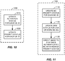
- FIG. 10 generally illustrates a method 1000 of allocating access.
- the method 1000 may be an implementation of the access allocation 520 depicted in FIG. 5 .
- the control device 610 will update the activation status 702 of one or more UE IDs 701 in order to allocate greater access or lesser access to any particular UE.
- the activation status 702 can be set to a default setting, updated manually, or triggered to shift upon the occurrence of a predetermined event such as acceptance of an invitation or validation by an administrator.
- the control device 610 will determine if there has been a manual update or triggering occurrence and update one or more UE IDs 701 accordingly.
- the control device 610 will update the UE priority status 703 of one or more UE IDs 701. As noted in some of the aforementioned scenarios, the UE priority status 703 can be set to a default setting or updated manually. Accordingly, at 1020, the control device 610 will determine if there has been a manual update and update the one or more UE IDs 701 accordingly. Additionally or alternatively, the control device 610 may rely on a UE priority determination device such as, for example, UE priority determination device 630. The UE priority determination device 630 may be configured to generate a UE priority status 703 that includes a weighting factor or coefficient that fits within a wide range of potential priority statuses.
- Factors that the UE priority determination device 630 might use to determine a UE priority status 703 include the following: random chance, as in a lottery; a round robin formula; a similarity between the media content preferences of UE and the media content preferences of other UEs; the number of followers associated with a UE on a social network; the length of time UE has been in a present status 704a; an arbitrary setting; by an administrator or other UE with high priority status; voting by other UEs, and/or weighted voting by other UEs, with votes being weighted in accordance with a UE priority status 703 associated with the voting UEs.
- FIG. 11 generally illustrates a method 1100 of facilitating playback.
- the method 1100 may be an implementation of the playback facilitation 530 depicted in FIG. 5 .
- the method 1100 may be performed by a control device such as, for example, control device 610.
- the control device 610 will update the MC priority status 805 of one or more MC IDs 801.
- the MC priority status 805 can be set to a default setting, updated manually, derived from a network, a social network, a subscription service, or the Internet, and/or copied from a previously-input list of media content.
- the control device 610 will determine if an update is necessary and update the MC priority status 805 of the one or more MC IDs 801 accordingly. Additionally or alternatively, the control device 610 may rely on a MC priority determination device such as, for example, the MC priority determination device 650.
- the MC priority determination device 650 may be configured to generate a MC priority status 805 that includes a weighting factor or coefficient that fits within a wide range of potential priority statuses.
- Factors that the MC priority determination device 650 might use to determine a MC priority status 805 include the following: an encoding technology of the MC (e.g., lossy versus lossless encoding); a bit rate of the MC; a sample rate of the MC; a similarity between the media content preferences associated with the media content and the media content preferences of the UEs having UE IDs (or the UEs having high priority status, or UEs having a present status, or any combination of the aforementioned); the length of time that the media content has been in a playback queue; the length of time required to complete playback of the media content; the number of times the media content has been requested; the number of requesting UEs that currently have a high priority status, active status, present status, or any of the above; and/or length of time since most recent playback.
- an encoding technology of the MC e.g., lossy versus lossless encoding
- a bit rate of the MC e.g.
- the MC priority determination device 650 may also determine the relative MC priority status 805 of different data files associated with the same MC. In one possible scenario, the MC priority determination device 650 recognizes two different files associated with the same MC, but assigns a higher MC priority status 805 to a data file with a higher sample rate.
- the control device 610 updates the DRM status 804 associated with one or more MC IDs 801.
- the MC IDs 801 with the highest MC priority status 805 are subjected to an update of the DRM status 804. This prevents needless updating of the DRM status 804 associated with media content that is not likely to be played back in the immediate future.
- the control device 610 updates the DRM status 804 every time there is a shift in the proximity status 704 associated with any UE ID 701.
- control device 610 directs the SMOD 660 to play back the highest-priority authenticated media content, as indicated by the DRM status 804 and MC priority status 805 associated with the media content.
- three guests associated with respective UE IDs 701 "1", “2”, and “3” are determined to have an active status 702a and a present status 704a.
- Guest “1” is a high-priority user associated with a high-priority UE status 703a, whereas guests “2" and “3” are associated with a low-priority UE status 703b.
- Guest “1” requests media content associated with MC ID 801 "M1”.
- Guest “2” requests media content associated with MC ID 801 "M2”.
- Guest “3” also requests media content associated with MC ID 801 "M2” and further requests media content associated with MC ID "M3”.
- control device 610 obtains MC identification data 802 (represented as “YYYY[M1]”, “YYYY[M2]”, and “YYYY[M3]” respectively) in accordance with any method set forth in the present disclosure.
- media content "M1” is stored on the UE 680 associated with guest “1".
- the fact that media content “M1” is stored locally on the UE of guest “1” is incorporated into MC identification data "YYYY[M1]”.
- the control device 610 also creates MC/UE association data 803 (represented as “ZZZZ[M1]") which identifies guest "1" as an authorized owner of media content "M1".
- media content "M2” can be acquired from a subscription service to which guest “2” has access.
- the location of streamable media content “M2” is incorporated into MC identification data "YYYY[M2]”.
- Guest “2” further supplies, for example, login information, which enables the control device to stream media content from a subscription service associated with guest "2". This login information may be incorporated into MC/UE association data 803 (represented as “ZZZZ[M2]").
- guest “3” who has no personal access to media content, seconds the request of guest “2” for media content “M2”, and further requests media content "M3", which he ascertains to be available on the subscription service available to guest "2".
- the control device 610 may make all the media content which is available via the subscription service browsable by one or more guests (e.g., guests with an active status 702a, high-priority UE status 703a, and/or a present status 704a).
- the location of the streamable media content "M3” is incorporated into MC identification data "YYYY[M3]”.
- Table 10 reflects the scenario as it has thus far been described.
- Table 10 MC ID MC Identification Data MC/UE Association Data
- DRM Status MC Priority Status M1 YYYY[M1] ZZZZ[M1] N/A N/A M2 YYYY[M2] ZZZZ[M2] N/A N/A M3 YYYY[M3] ZZZZ[M3] N/A N/A
- the control device 610 will next ascertain the DRM status 804 associated with each requested unit of media content "M1", “M2", and "M3". With respect to "M1", the control device 610 uses data "ZZZZ[M1]” to ascertain that guest “1" (associated with UE ID "1") is authorized to play back media content "MC1". Control device 610 subsequently consults the UE data table 700 to ascertain the proximity status 704 associated with UE ID "1". If an absent status 704b were associated with UE ID "1”, then the DRM status 804 associated with MC ID "1” will be set to a blocked status 804b. However, in this scenario, a present status 704a is associated with UE ID "1", and the DRM status 804 associated with MC ID "1" will be set to an authenticated status 804a.
- control device 610 uses data "ZZZZ[M2]” and “ZZZZ[M3]” respectively to ascertain that guest “2" (associated with UE ID "2") is authorized to play back media content "MC2" and "MC3" via the subscription service.
- Control device 610 subsequently consults the UE data table 700 to ascertain the proximity status 704 associated with UE ID "2".
- a present status 704a is associated with UE ID "2”
- the DRM status 804 associated with MC IDs "2" and “3” will be set to an authenticated status 804a.
- Table 11 reflects the scenario as it has thus far been described.
- control device 610 will only facilitate playback of media content if the control device 610 has authenticated user-specific digital ownership rights associated with the media content.
- the control device 610 will next ascertain the MC priority status 805 associated with each requested unit of media content "M1", “M2", and "M3".
- the MC priority status 805 may be determined in accordance with any method set forth in the present disclosure.
- the MC priority status 805 is denominated as a rank ordering "#1", “#2", “#3”, etc., in which the highest ranked media content (“#1") is first in the playback queue.
- the different factors that affect the MC priority status 805 are arbitrarily weighted for the purposes of illustration.
- media content "M1” is ranked higher than media content "M3” because media content "M1” was requested by guest “1”, who is associated with a high-priority UE status 703a, whereas media content "M3” was requested by guest “3", who is associated with a low-priority UE status 703b.
- media content "M1” is ranked higher than media content "M3” because media content "M1” was requested by guest “1", who is associated with ownership and/or authorization of the media content “M1” he requested (as can be ascertained from MC/UE association data "ZZZZ[M1]” 803), whereas media content "M3” was requested by guest “3", who is not associated with ownership/authorization of the media content "M3” he requested (as can be ascertained from MC/UE association data "ZZZZ[M3]” 803).
- Table 12 reflects the scenario as it has thus far been described.
- Table 12 MC ID MC Identification Data MC/UE Asso-ciation Data DRM Status MC Priority Status M1 YYYY[M1] ZZZZ[M1] AUTHENTIC. #2 M2 YYYY[M2] ZZZZ[M2] AUTHENTIC. #1 M3 YYYY[M3] ZZZZ[M3] AUTHENTIC. #3
- the number of requests associated with a given unit of media content is weighted more heavily relative to the UE priority status 703 of the guest who requests a given unit of media content.
- the control device 610 is configurable such that any weighting system is possible.
- the control device 610 will begin facilitation of playback.
- the control device 610 will first identify the MC ID 801 associated with a "#1" MC priority status, in this case, "M2". Next, it will ascertain the DRM status associated with media content "M2". If the DRM status 804 associated with media content "M2" is an authenticated status 804a, then the control device 610 may facilitate playback of the media content associated with MC ID "M2". In some scenarios, the MC/UE association data "ZZZZ[M2]" is relied upon to facilitate playback.
- control device 610 may derive a link to a media content stream from the MC/UE association data "ZZZZ[M2]” and utilize login information stored in the MC/UE association data "ZZZZ[M2]" to access the media content stream via a subscription service.
- control device 610 may affect the MC priority status 805 associated with media content "M2". This reflects the fact that once a request is granted, the MC priority status 805 associated with the requested media content should be lowered.
- the MC priority status 805 associated with media content "M2" is lowered in response to the fact that control device 610 has played back the media content "M2". Accordingly, the MC priority status 805 associated with the remainder of the requested media content ("M1" and "M3") is raised. Moreover, the PDD 670 has determined that guest "1" is no longer within the proximity zone 671, and the control device 610 accordingly sets the proximity status 704 associated with UE ID "1" to an absent status 704b. Table 13 reflects the scenario as it has thus far been described.
- Table 13 MC ID MC Identification Data MC/UE Asso-ciation Data DRM Status MC Priority Status M1 YYYY[M1] ZZZZ[M1] AUTHENTIC. #1 M2 YYYY[M2] ZZZZ[M2] AUTHENTIC. N/A M3 YYYY[M3] ZZZZ[M3] AUTHENTIC. #2
- control device 610 finishes the playback of media content "M2" and then consults the MC data table 800 to determine the next media content to be played back.
- the control device 610 will first identify the MC ID 801 associated with a "#1" MC priority status, in this case, "M1".
- the control device 610 will ascertain the DRM status associated with media content "M1” by utilizing the MC/UE association data 803 associated with MC ID "M1" and the data stored in UE data table 700.
- the control device 610 may continually update the MC/UE association data 803 such that if any UE ID is associated with ownership/authorization of a specific unit of media content, the fact of the association is reflected in the MC/UE association data 803. For example, the control device 610 may recognize that the subscription service associated with guest "2" gives authorization for streaming of media content "M1". In this case, the MC/UE association data 803 would be updated to reflect the fact that not only guest "1" but guest “2" is authorized to play back the media content "M1". In another example, a new guest "4" arrives and UE ID "4" is added to the UE data table 700. The control device 610 may interrogate the UE associated with new guest "4" to determine if UE ID "4" is associated with ownership/authorization related to any of media content "M1", “M2", or "M3".
- control device 610 utilizes MC/UE association data "ZZZZ[M1]” to ascertain that UE ID 701 (guest "1") is the only UE ID associated with media content "M1".
- MC/UE association data "ZZZZ[M1]” indicates that guest “1” (associated with UE ID "1") is the only guest associated with ownership/authorization of media content "M1”. Therefore, control device 610 will consult the UE data table 700 to confirm that UE ID "1" is associated with a present status 704a.
- the PDD 670 has determined that the UE associated with UE ID "1" is no longer present, and the control device 610 has accordingly set the proximity status 704 associated with UE ID "1" to an absent status 704b. As a result, the control device 610 sets the DRM status 804 associated with MC ID "1" to a blocked status 804b.
- Table 14 reflects the scenario as it has thus far been described. Table 14 MC ID MC Identification Data MC/UE Asso-ciation Data DRM Status MC Priority Status M1 YYYY[M1] ZZZZ[M1] BLOCKED #1 M2 YYYY[M2] ZZZZ[M2] AUTHENTIC. N/A M3 YYYY[M3] ZZZZ[M3] AUTHENTIC. #2
- control device 610 will not play back the media content "M1". Instead, it will update the DRM status 804 associated with the next-highest ranked media content, i.e., media content "M3" which has an MC priority status of "#2".
- the control device then repeats the process of ascertaining the DRM status associated with media content "M3” by utilizing the MC/UE association data "ZZZZ[M3]" associated with MC ID "M3" and the data stored in UE data table 700.
- the control device 610 is configured to update the UE data table 700 and the MC data table 800. As a result, the control device 610 is able to facilitate playback on the SMOD 660 of media content with an authenticated status 804a and a high-priority MC status 805a.
- DSP digital signal processor
- ASIC application specific integrated circuit
- FPGA field programmable gate array
- a general purpose processor may be a microprocessor, but in the alternative, the processor may be any conventional processor, controller, microcontroller, or state machine.
- a processor may also be implemented as a combination of computing devices, e.g., a combination of a DSP and a microprocessor, a plurality of microprocessors, one or more microprocessors in conjunction with a DSP core, or any other such configuration.
- a software module may reside in RAM memory, flash memory, ROM memory, EPROM memory, EEPROM memory, registers, hard disk, a removable disk, a CD-ROM, or any other form of storage medium known in the art.
- An exemplary storage medium is coupled to the processor such that the processor can read information from, and write information to, the storage medium.
- the storage medium may be integral to the processor.
- the processor and the storage medium may reside in an ASIC.
- the ASIC may reside in a user terminal (e.g., UE).
- the processor and the storage medium may reside as discrete components in a user terminal.
- Non-transitory computer-readable media includes both computer storage media and communication media including any medium that facilitates transfer of a computer program from one place to another.
- a storage media may be any available media that can be accessed by a computer.
- non-transitory computer-readable media can comprise RAM, ROM, EEPROM, CD-ROM or other optical disk storage, magnetic disk storage or other magnetic storage devices, or any other medium that can be used to carry or store desired program code in the form of instructions or data structures and that can be accessed by a computer. Also, any connection is properly termed a non-transitory computer-readable medium.
- Disk and disc includes compact disc (CD), laser disc, optical disc, digital versatile disc (DVD), floppy disk and blu-ray disc where disks usually reproduce data magnetically, while discs reproduce data optically with lasers. Combinations of the above should also be included within the scope of non-transitory computer-readable media.
Landscapes
- Engineering & Computer Science (AREA)
- Signal Processing (AREA)
- Multimedia (AREA)
- Computer Networks & Wireless Communication (AREA)
- Computer Security & Cryptography (AREA)
- Databases & Information Systems (AREA)
- General Engineering & Computer Science (AREA)
- Computer Hardware Design (AREA)
- Human Computer Interaction (AREA)
- Software Systems (AREA)
- Theoretical Computer Science (AREA)
- Computing Systems (AREA)
- Technology Law (AREA)
- Physics & Mathematics (AREA)
- General Physics & Mathematics (AREA)
- Telephonic Communication Services (AREA)
- Mobile Radio Communication Systems (AREA)
- Power Engineering (AREA)
- Information Transfer Between Computers (AREA)
- Telephone Function (AREA)
Applications Claiming Priority (3)
| Application Number | Priority Date | Filing Date | Title |
|---|---|---|---|
| US201462019775P | 2014-07-01 | 2014-07-01 | |
| US14/754,095 US20160004845A1 (en) | 2014-07-01 | 2015-06-29 | Access allocation for a shared media output device |
| PCT/US2015/038825 WO2016004201A1 (en) | 2014-07-01 | 2015-07-01 | Access allocation for a shared media output device |
Publications (2)
| Publication Number | Publication Date |
|---|---|
| EP3165010A1 EP3165010A1 (en) | 2017-05-10 |
| EP3165010B1 true EP3165010B1 (en) | 2018-03-07 |
Family
ID=55017183
Family Applications (1)
| Application Number | Title | Priority Date | Filing Date |
|---|---|---|---|
| EP15747265.5A Not-in-force EP3165010B1 (en) | 2014-07-01 | 2015-07-01 | Access allocation for a shared media output device |
Country Status (5)
| Country | Link |
|---|---|
| US (1) | US20160004845A1 (enExample) |
| EP (1) | EP3165010B1 (enExample) |
| JP (1) | JP2017522806A (enExample) |
| CN (1) | CN106664451A (enExample) |
| WO (1) | WO2016004201A1 (enExample) |
Families Citing this family (7)
| Publication number | Priority date | Publication date | Assignee | Title |
|---|---|---|---|---|
| US9859731B2 (en) * | 2016-01-15 | 2018-01-02 | International Business Machines Corporation | Alternate alarm notifications based on battery condition |
| WO2018213004A1 (en) * | 2017-05-16 | 2018-11-22 | Apple Inc. | Credential delegation |
| US11893585B2 (en) | 2019-05-31 | 2024-02-06 | Apple Inc. | Associating multiple user accounts with a content output device |
| US11122302B1 (en) * | 2019-11-06 | 2021-09-14 | Securas Technologies, LLC | Dynamic controlled-environment facility resident media broadcasting service |
| US11444949B1 (en) * | 2020-01-15 | 2022-09-13 | Verizon Patent And Licensing Inc. | Systems and methods for secure selection of a user profile in a shared context |
| US11637880B2 (en) * | 2021-05-06 | 2023-04-25 | Spotify Ab | Device discovery for social playback |
| US12346537B2 (en) * | 2022-11-01 | 2025-07-01 | Phunware, Inc. | Proximity-enabled machine control system |
Family Cites Families (8)
| Publication number | Priority date | Publication date | Assignee | Title |
|---|---|---|---|---|
| AU2003304608A1 (en) * | 2003-12-08 | 2005-06-29 | Nokia Corporation | Method and device for sharing of content protected by digital rights management |
| US20070033607A1 (en) * | 2005-08-08 | 2007-02-08 | Bryan David A | Presence and proximity responsive program display |
| US7730184B2 (en) * | 2005-11-17 | 2010-06-01 | Sony Ericsson Mobile Communications Ab | Digital rights management based on device proximity |
| US9129087B2 (en) * | 2011-12-30 | 2015-09-08 | Rovi Guides, Inc. | Systems and methods for managing digital rights based on a union or intersection of individual rights |
| US9258342B2 (en) * | 2012-08-09 | 2016-02-09 | Actv8, Inc. | Method and apparatus for interactive mobile offer system using time and location for out-of-home display screens |
| JP6285365B2 (ja) * | 2012-11-09 | 2018-02-28 | ソニー株式会社 | 通信端末、通信方法、プログラム、及び通信システム |
| US20150199165A1 (en) * | 2014-01-16 | 2015-07-16 | Nvidia Corporation | Automatic proximity display switching for a miracast environment |
| US20160119438A1 (en) * | 2014-10-23 | 2016-04-28 | Google Inc. | Systems and methods of sharing media and data content across devices through local proximity |
-
2015
- 2015-06-29 US US14/754,095 patent/US20160004845A1/en not_active Abandoned
- 2015-07-01 WO PCT/US2015/038825 patent/WO2016004201A1/en not_active Ceased
- 2015-07-01 CN CN201580035718.7A patent/CN106664451A/zh active Pending
- 2015-07-01 EP EP15747265.5A patent/EP3165010B1/en not_active Not-in-force
- 2015-07-01 JP JP2016574953A patent/JP2017522806A/ja active Pending
Also Published As
| Publication number | Publication date |
|---|---|
| CN106664451A (zh) | 2017-05-10 |
| US20160004845A1 (en) | 2016-01-07 |
| JP2017522806A (ja) | 2017-08-10 |
| EP3165010A1 (en) | 2017-05-10 |
| WO2016004201A1 (en) | 2016-01-07 |
Similar Documents
| Publication | Publication Date | Title |
|---|---|---|
| EP3165010B1 (en) | Access allocation for a shared media output device | |
| US11818131B2 (en) | Systems and methods for scalable-factor authentication | |
| US11601429B2 (en) | Network service control for access to wireless radio networks | |
| EP3078201B1 (en) | Mobile device generated sharing of cloud media collections | |
| US10673985B2 (en) | Router-host logging | |
| KR101810324B1 (ko) | 무선 디바이스들에 대한 프라이버시 향상 | |
| US9276882B2 (en) | System and method for online fan meeting | |
| US20130290494A1 (en) | Session management for communication in a heterogeneous network | |
| US9516466B2 (en) | Establishing presence by identifying audio sample and position | |
| US10104423B2 (en) | Multimedia service mirroring | |
| US20140324591A1 (en) | Selectively authenticating a group of devices as being in a shared environment based on locally captured ambient sound | |
| CN106134143A (zh) | 用于动态网络接入管理的方法、设备和系统 | |
| US12375916B2 (en) | User authentication | |
| KR20160125427A (ko) | 우선순위 액세스 채널에 대한 우선순위 액세스 | |
| CN113170276B (zh) | 用于递送局限于预定义服务区域的专用服务的方法和系统 | |
| WO2014039047A1 (en) | Methods and apparatus for network sharing control |
Legal Events
| Date | Code | Title | Description |
|---|---|---|---|
| PUAI | Public reference made under article 153(3) epc to a published international application that has entered the european phase |
Free format text: ORIGINAL CODE: 0009012 |
|
| 17P | Request for examination filed |
Effective date: 20161117 |
|
| AK | Designated contracting states |
Kind code of ref document: A1 Designated state(s): AL AT BE BG CH CY CZ DE DK EE ES FI FR GB GR HR HU IE IS IT LI LT LU LV MC MK MT NL NO PL PT RO RS SE SI SK SM TR |
|
| AX | Request for extension of the european patent |
Extension state: BA ME |
|
| DAV | Request for validation of the european patent (deleted) | ||
| DAX | Request for extension of the european patent (deleted) | ||
| GRAP | Despatch of communication of intention to grant a patent |
Free format text: ORIGINAL CODE: EPIDOSNIGR1 |
|
| RIC1 | Information provided on ipc code assigned before grant |
Ipc: G06F 21/10 20130101ALN20170929BHEP Ipc: H04N 21/41 20110101ALI20170929BHEP Ipc: H04N 21/482 20110101ALN20170929BHEP Ipc: H04W 4/02 20090101AFI20170929BHEP Ipc: H04N 21/432 20110101ALN20170929BHEP Ipc: H04W 12/06 20090101ALN20170929BHEP Ipc: H04W 12/08 20090101ALN20170929BHEP Ipc: H04L 29/06 20060101ALN20170929BHEP Ipc: H04N 21/258 20110101ALI20170929BHEP |
|
| INTG | Intention to grant announced |
Effective date: 20171020 |
|
| GRAS | Grant fee paid |
Free format text: ORIGINAL CODE: EPIDOSNIGR3 |
|
| GRAA | (expected) grant |
Free format text: ORIGINAL CODE: 0009210 |
|
| AK | Designated contracting states |
Kind code of ref document: B1 Designated state(s): AL AT BE BG CH CY CZ DE DK EE ES FI FR GB GR HR HU IE IS IT LI LT LU LV MC MK MT NL NO PL PT RO RS SE SI SK SM TR |
|
| REG | Reference to a national code |
Ref country code: GB Ref legal event code: FG4D |
|
| REG | Reference to a national code |
Ref country code: CH Ref legal event code: EP Ref country code: AT Ref legal event code: REF Ref document number: 977817 Country of ref document: AT Kind code of ref document: T Effective date: 20180315 |
|
| REG | Reference to a national code |
Ref country code: DE Ref legal event code: R096 Ref document number: 602015008596 Country of ref document: DE |
|
| REG | Reference to a national code |
Ref country code: IE Ref legal event code: FG4D |
|
| REG | Reference to a national code |
Ref country code: FR Ref legal event code: PLFP Year of fee payment: 4 |
|
| REG | Reference to a national code |
Ref country code: NL Ref legal event code: MP Effective date: 20180307 |
|
| REG | Reference to a national code |
Ref country code: LT Ref legal event code: MG4D |
|
| PG25 | Lapsed in a contracting state [announced via postgrant information from national office to epo] |
Ref country code: NO Free format text: LAPSE BECAUSE OF FAILURE TO SUBMIT A TRANSLATION OF THE DESCRIPTION OR TO PAY THE FEE WITHIN THE PRESCRIBED TIME-LIMIT Effective date: 20180607 Ref country code: CY Free format text: LAPSE BECAUSE OF FAILURE TO SUBMIT A TRANSLATION OF THE DESCRIPTION OR TO PAY THE FEE WITHIN THE PRESCRIBED TIME-LIMIT Effective date: 20180307 Ref country code: LT Free format text: LAPSE BECAUSE OF FAILURE TO SUBMIT A TRANSLATION OF THE DESCRIPTION OR TO PAY THE FEE WITHIN THE PRESCRIBED TIME-LIMIT Effective date: 20180307 Ref country code: ES Free format text: LAPSE BECAUSE OF FAILURE TO SUBMIT A TRANSLATION OF THE DESCRIPTION OR TO PAY THE FEE WITHIN THE PRESCRIBED TIME-LIMIT Effective date: 20180307 Ref country code: HR Free format text: LAPSE BECAUSE OF FAILURE TO SUBMIT A TRANSLATION OF THE DESCRIPTION OR TO PAY THE FEE WITHIN THE PRESCRIBED TIME-LIMIT Effective date: 20180307 Ref country code: FI Free format text: LAPSE BECAUSE OF FAILURE TO SUBMIT A TRANSLATION OF THE DESCRIPTION OR TO PAY THE FEE WITHIN THE PRESCRIBED TIME-LIMIT Effective date: 20180307 |
|
| REG | Reference to a national code |
Ref country code: AT Ref legal event code: MK05 Ref document number: 977817 Country of ref document: AT Kind code of ref document: T Effective date: 20180307 |
|
| PG25 | Lapsed in a contracting state [announced via postgrant information from national office to epo] |
Ref country code: GR Free format text: LAPSE BECAUSE OF FAILURE TO SUBMIT A TRANSLATION OF THE DESCRIPTION OR TO PAY THE FEE WITHIN THE PRESCRIBED TIME-LIMIT Effective date: 20180608 Ref country code: BG Free format text: LAPSE BECAUSE OF FAILURE TO SUBMIT A TRANSLATION OF THE DESCRIPTION OR TO PAY THE FEE WITHIN THE PRESCRIBED TIME-LIMIT Effective date: 20180607 Ref country code: RS Free format text: LAPSE BECAUSE OF FAILURE TO SUBMIT A TRANSLATION OF THE DESCRIPTION OR TO PAY THE FEE WITHIN THE PRESCRIBED TIME-LIMIT Effective date: 20180307 Ref country code: SE Free format text: LAPSE BECAUSE OF FAILURE TO SUBMIT A TRANSLATION OF THE DESCRIPTION OR TO PAY THE FEE WITHIN THE PRESCRIBED TIME-LIMIT Effective date: 20180307 Ref country code: LV Free format text: LAPSE BECAUSE OF FAILURE TO SUBMIT A TRANSLATION OF THE DESCRIPTION OR TO PAY THE FEE WITHIN THE PRESCRIBED TIME-LIMIT Effective date: 20180307 |
|
| PGFP | Annual fee paid to national office [announced via postgrant information from national office to epo] |
Ref country code: FR Payment date: 20180622 Year of fee payment: 4 |
|
| PG25 | Lapsed in a contracting state [announced via postgrant information from national office to epo] |
Ref country code: NL Free format text: LAPSE BECAUSE OF FAILURE TO SUBMIT A TRANSLATION OF THE DESCRIPTION OR TO PAY THE FEE WITHIN THE PRESCRIBED TIME-LIMIT Effective date: 20180307 Ref country code: AL Free format text: LAPSE BECAUSE OF FAILURE TO SUBMIT A TRANSLATION OF THE DESCRIPTION OR TO PAY THE FEE WITHIN THE PRESCRIBED TIME-LIMIT Effective date: 20180307 Ref country code: PL Free format text: LAPSE BECAUSE OF FAILURE TO SUBMIT A TRANSLATION OF THE DESCRIPTION OR TO PAY THE FEE WITHIN THE PRESCRIBED TIME-LIMIT Effective date: 20180307 Ref country code: RO Free format text: LAPSE BECAUSE OF FAILURE TO SUBMIT A TRANSLATION OF THE DESCRIPTION OR TO PAY THE FEE WITHIN THE PRESCRIBED TIME-LIMIT Effective date: 20180307 Ref country code: IT Free format text: LAPSE BECAUSE OF FAILURE TO SUBMIT A TRANSLATION OF THE DESCRIPTION OR TO PAY THE FEE WITHIN THE PRESCRIBED TIME-LIMIT Effective date: 20180307 Ref country code: EE Free format text: LAPSE BECAUSE OF FAILURE TO SUBMIT A TRANSLATION OF THE DESCRIPTION OR TO PAY THE FEE WITHIN THE PRESCRIBED TIME-LIMIT Effective date: 20180307 |
|
| PG25 | Lapsed in a contracting state [announced via postgrant information from national office to epo] |
Ref country code: CZ Free format text: LAPSE BECAUSE OF FAILURE TO SUBMIT A TRANSLATION OF THE DESCRIPTION OR TO PAY THE FEE WITHIN THE PRESCRIBED TIME-LIMIT Effective date: 20180307 Ref country code: AT Free format text: LAPSE BECAUSE OF FAILURE TO SUBMIT A TRANSLATION OF THE DESCRIPTION OR TO PAY THE FEE WITHIN THE PRESCRIBED TIME-LIMIT Effective date: 20180307 Ref country code: SM Free format text: LAPSE BECAUSE OF FAILURE TO SUBMIT A TRANSLATION OF THE DESCRIPTION OR TO PAY THE FEE WITHIN THE PRESCRIBED TIME-LIMIT Effective date: 20180307 Ref country code: SK Free format text: LAPSE BECAUSE OF FAILURE TO SUBMIT A TRANSLATION OF THE DESCRIPTION OR TO PAY THE FEE WITHIN THE PRESCRIBED TIME-LIMIT Effective date: 20180307 |
|
| REG | Reference to a national code |
Ref country code: DE Ref legal event code: R097 Ref document number: 602015008596 Country of ref document: DE |
|
| PG25 | Lapsed in a contracting state [announced via postgrant information from national office to epo] |
Ref country code: PT Free format text: LAPSE BECAUSE OF FAILURE TO SUBMIT A TRANSLATION OF THE DESCRIPTION OR TO PAY THE FEE WITHIN THE PRESCRIBED TIME-LIMIT Effective date: 20180709 |
|
| PLBE | No opposition filed within time limit |
Free format text: ORIGINAL CODE: 0009261 |
|
| STAA | Information on the status of an ep patent application or granted ep patent |
Free format text: STATUS: NO OPPOSITION FILED WITHIN TIME LIMIT |
|
| PG25 | Lapsed in a contracting state [announced via postgrant information from national office to epo] |
Ref country code: DK Free format text: LAPSE BECAUSE OF FAILURE TO SUBMIT A TRANSLATION OF THE DESCRIPTION OR TO PAY THE FEE WITHIN THE PRESCRIBED TIME-LIMIT Effective date: 20180307 |
|
| REG | Reference to a national code |
Ref country code: DE Ref legal event code: R119 Ref document number: 602015008596 Country of ref document: DE |
|
| 26N | No opposition filed |
Effective date: 20181210 |
|
| REG | Reference to a national code |
Ref country code: CH Ref legal event code: PL |
|
| PG25 | Lapsed in a contracting state [announced via postgrant information from national office to epo] |
Ref country code: MC Free format text: LAPSE BECAUSE OF FAILURE TO SUBMIT A TRANSLATION OF THE DESCRIPTION OR TO PAY THE FEE WITHIN THE PRESCRIBED TIME-LIMIT Effective date: 20180307 Ref country code: LU Free format text: LAPSE BECAUSE OF NON-PAYMENT OF DUE FEES Effective date: 20180701 |
|
| REG | Reference to a national code |
Ref country code: BE Ref legal event code: MM Effective date: 20180731 |
|
| REG | Reference to a national code |
Ref country code: IE Ref legal event code: MM4A |
|
| PG25 | Lapsed in a contracting state [announced via postgrant information from national office to epo] |
Ref country code: IE Free format text: LAPSE BECAUSE OF NON-PAYMENT OF DUE FEES Effective date: 20180701 Ref country code: DE Free format text: LAPSE BECAUSE OF NON-PAYMENT OF DUE FEES Effective date: 20190201 Ref country code: CH Free format text: LAPSE BECAUSE OF NON-PAYMENT OF DUE FEES Effective date: 20180731 Ref country code: LI Free format text: LAPSE BECAUSE OF NON-PAYMENT OF DUE FEES Effective date: 20180731 |
|
| PG25 | Lapsed in a contracting state [announced via postgrant information from national office to epo] |
Ref country code: BE Free format text: LAPSE BECAUSE OF NON-PAYMENT OF DUE FEES Effective date: 20180731 |
|
| PG25 | Lapsed in a contracting state [announced via postgrant information from national office to epo] |
Ref country code: MT Free format text: LAPSE BECAUSE OF NON-PAYMENT OF DUE FEES Effective date: 20180701 |
|
| GBPC | Gb: european patent ceased through non-payment of renewal fee |
Effective date: 20190701 |
|
| PG25 | Lapsed in a contracting state [announced via postgrant information from national office to epo] |
Ref country code: TR Free format text: LAPSE BECAUSE OF FAILURE TO SUBMIT A TRANSLATION OF THE DESCRIPTION OR TO PAY THE FEE WITHIN THE PRESCRIBED TIME-LIMIT Effective date: 20180307 |
|
| PG25 | Lapsed in a contracting state [announced via postgrant information from national office to epo] |
Ref country code: GB Free format text: LAPSE BECAUSE OF NON-PAYMENT OF DUE FEES Effective date: 20190701 |
|
| PG25 | Lapsed in a contracting state [announced via postgrant information from national office to epo] |
Ref country code: MK Free format text: LAPSE BECAUSE OF NON-PAYMENT OF DUE FEES Effective date: 20180307 Ref country code: FR Free format text: LAPSE BECAUSE OF NON-PAYMENT OF DUE FEES Effective date: 20190731 Ref country code: HU Free format text: LAPSE BECAUSE OF FAILURE TO SUBMIT A TRANSLATION OF THE DESCRIPTION OR TO PAY THE FEE WITHIN THE PRESCRIBED TIME-LIMIT; INVALID AB INITIO Effective date: 20150701 |
|
| PG25 | Lapsed in a contracting state [announced via postgrant information from national office to epo] |
Ref country code: IS Free format text: LAPSE BECAUSE OF FAILURE TO SUBMIT A TRANSLATION OF THE DESCRIPTION OR TO PAY THE FEE WITHIN THE PRESCRIBED TIME-LIMIT Effective date: 20180707 |
|
| PG25 | Lapsed in a contracting state [announced via postgrant information from national office to epo] |
Ref country code: SI Free format text: LAPSE BECAUSE OF NON-PAYMENT OF DUE FEES Effective date: 20180701 |