EP3163907A1 - Electroacoustic transducer - Google Patents
Electroacoustic transducer Download PDFInfo
- Publication number
- EP3163907A1 EP3163907A1 EP15810941.3A EP15810941A EP3163907A1 EP 3163907 A1 EP3163907 A1 EP 3163907A1 EP 15810941 A EP15810941 A EP 15810941A EP 3163907 A1 EP3163907 A1 EP 3163907A1
- Authority
- EP
- European Patent Office
- Prior art keywords
- vertically split
- split cylindrical
- speaker
- housing
- vibrating body
- Prior art date
- Legal status (The legal status is an assumption and is not a legal conclusion. Google has not performed a legal analysis and makes no representation as to the accuracy of the status listed.)
- Withdrawn
Links
Images








Classifications
-
- H—ELECTRICITY
- H04—ELECTRIC COMMUNICATION TECHNIQUE
- H04R—LOUDSPEAKERS, MICROPHONES, GRAMOPHONE PICK-UPS OR LIKE ACOUSTIC ELECTROMECHANICAL TRANSDUCERS; ELECTRIC HEARING AIDS; PUBLIC ADDRESS SYSTEMS
- H04R9/00—Transducers of moving-coil, moving-strip, or moving-wire type
- H04R9/02—Details
-
- H—ELECTRICITY
- H04—ELECTRIC COMMUNICATION TECHNIQUE
- H04R—LOUDSPEAKERS, MICROPHONES, GRAMOPHONE PICK-UPS OR LIKE ACOUSTIC ELECTROMECHANICAL TRANSDUCERS; ELECTRIC HEARING AIDS; PUBLIC ADDRESS SYSTEMS
- H04R9/00—Transducers of moving-coil, moving-strip, or moving-wire type
- H04R9/06—Loudspeakers
-
- H—ELECTRICITY
- H04—ELECTRIC COMMUNICATION TECHNIQUE
- H04R—LOUDSPEAKERS, MICROPHONES, GRAMOPHONE PICK-UPS OR LIKE ACOUSTIC ELECTROMECHANICAL TRANSDUCERS; ELECTRIC HEARING AIDS; PUBLIC ADDRESS SYSTEMS
- H04R1/00—Details of transducers, loudspeakers or microphones
- H04R1/02—Casings; Cabinets ; Supports therefor; Mountings therein
- H04R1/025—Arrangements for fixing loudspeaker transducers, e.g. in a box, furniture
-
- H—ELECTRICITY
- H04—ELECTRIC COMMUNICATION TECHNIQUE
- H04R—LOUDSPEAKERS, MICROPHONES, GRAMOPHONE PICK-UPS OR LIKE ACOUSTIC ELECTROMECHANICAL TRANSDUCERS; ELECTRIC HEARING AIDS; PUBLIC ADDRESS SYSTEMS
- H04R7/00—Diaphragms for electromechanical transducers; Cones
- H04R7/02—Diaphragms for electromechanical transducers; Cones characterised by the construction
- H04R7/12—Non-planar diaphragms or cones
-
- H—ELECTRICITY
- H04—ELECTRIC COMMUNICATION TECHNIQUE
- H04R—LOUDSPEAKERS, MICROPHONES, GRAMOPHONE PICK-UPS OR LIKE ACOUSTIC ELECTROMECHANICAL TRANSDUCERS; ELECTRIC HEARING AIDS; PUBLIC ADDRESS SYSTEMS
- H04R7/00—Diaphragms for electromechanical transducers; Cones
- H04R7/16—Mounting or tensioning of diaphragms or cones
- H04R7/18—Mounting or tensioning of diaphragms or cones at the periphery
- H04R7/20—Securing diaphragm or cone resiliently to support by flexible material, springs, cords, or strands
-
- H—ELECTRICITY
- H04—ELECTRIC COMMUNICATION TECHNIQUE
- H04R—LOUDSPEAKERS, MICROPHONES, GRAMOPHONE PICK-UPS OR LIKE ACOUSTIC ELECTROMECHANICAL TRANSDUCERS; ELECTRIC HEARING AIDS; PUBLIC ADDRESS SYSTEMS
- H04R7/00—Diaphragms for electromechanical transducers; Cones
- H04R7/16—Mounting or tensioning of diaphragms or cones
- H04R7/24—Tensioning by means acting directly on free portions of diaphragm or cone
-
- H—ELECTRICITY
- H04—ELECTRIC COMMUNICATION TECHNIQUE
- H04R—LOUDSPEAKERS, MICROPHONES, GRAMOPHONE PICK-UPS OR LIKE ACOUSTIC ELECTROMECHANICAL TRANSDUCERS; ELECTRIC HEARING AIDS; PUBLIC ADDRESS SYSTEMS
- H04R9/00—Transducers of moving-coil, moving-strip, or moving-wire type
- H04R9/02—Details
- H04R9/04—Construction, mounting, or centering of coil
-
- H—ELECTRICITY
- H04—ELECTRIC COMMUNICATION TECHNIQUE
- H04R—LOUDSPEAKERS, MICROPHONES, GRAMOPHONE PICK-UPS OR LIKE ACOUSTIC ELECTROMECHANICAL TRANSDUCERS; ELECTRIC HEARING AIDS; PUBLIC ADDRESS SYSTEMS
- H04R2400/00—Loudspeakers
- H04R2400/01—Transducers used as a loudspeaker to generate sound aswell as a microphone to detect sound
-
- H—ELECTRICITY
- H04—ELECTRIC COMMUNICATION TECHNIQUE
- H04R—LOUDSPEAKERS, MICROPHONES, GRAMOPHONE PICK-UPS OR LIKE ACOUSTIC ELECTROMECHANICAL TRANSDUCERS; ELECTRIC HEARING AIDS; PUBLIC ADDRESS SYSTEMS
- H04R2400/00—Loudspeakers
- H04R2400/11—Aspects regarding the frame of loudspeaker transducers
Definitions
- the present invention relates to an electroacoustic transducer suitable for a speaker for reproducing sound or a microphone for collecting sound through the vibration of vertically split cylindrical faces.
- Speakers having a curved diaphragm such as riffell speakers, are known as a type of various speakers for reproducing sound.
- Patent Document 1 discloses an illumination apparatus with a speaker in which a diaphragm (speaker diaphragm) is made of a light-transmittable material and used as the protection cover of a lighting lamp.
- the diaphragm is installed on a box-shaped frame.
- Patent Document 2 discloses a speaker in which two vertically split cylindrical diaphragms are integrally disposed in parallel in the same direction and the edges of the diaphragms are fixed to a frame.
- Patent Document 2 also discloses a speaker in which two sets of vertically split cylindrical diaphragms, closed from each other, are disposed integrally in parallel in a circumferential direction and a speaker in which four vertically split cylindrical diaphragms are disposed back to back in parallel.
- These four diaphragms are configured such that the joining sections of the respective diaphragms are supported by the magnetic circuits or the voice coil bobbins disposed inside, and all the diaphragms are disposed so that the curved faces thereof are directed outward.
- Patent Document 3 discloses a speaker in which two diaphragms are provided in parallel and both the end sections of the diaphragm are elastically supported by a frame so that the central section of the diaphragm is curved.
- the frame of this speaker has an almost line-symmetric shape in which a pair of flat plate sections is connected to each other with a central connection section.
- speakers having a curved diaphragm are configured such that the end sections of the diaphragm are fixed to a rectangular frame, and the diaphragm and the housing of each speaker are separated in the external appearance of the speaker, whereby the speakers have similar external appearances.
- this kind of electroacoustic transducer should be further improved in design property.
- the present invention has been made in consideration of the above-mentioned circumstances, and an object of the present invention is to provide an electroacoustic transducer having a curved vibration face and being excellent in acoustic characteristics and excellent in design property.
- An electroacoustic transducer includes a vibrating body having one or more vertically split cylindrical faces; a housing having fixing sections that fix side sections of the vertically split cylindrical faces of the vibrating body; and a conversion section that converts a signal into vibration of the vibrating body, wherein the vibrating body is extended to a surface of the housing in directions to the side sections of the vertically split cylindrical faces instead of being extended to the fixing sections.
- An electroacoustic transducer includes a vibrating body having one or more vertically split cylindrical faces; a housing having connection sections that are joined to side sections of the vertically split cylindrical faces of the vibrating body; and a conversion section that converts an electrical signal into vibration of the vibrating body, wherein the side sections of the vertically split cylindrical faces are formed so as to be flush with the connection sections of the housing.
- the vibrating body and the housing can have design with a smooth integral feeling without being distinguished from each other, an electroacoustic transducer being excellent in acoustic characteristics and excellent in design property can be provided.
- Figs. 1 and 2 show a speaker according to a first embodiment of the present invention.
- a speaker (electroacoustic transducer) 100 includes a vibrating body 1 having one or more vertically split cylindrical faces 5, an actuator (conversion section) 2 reciprocating the vibrating body 1, and a housing 3 for supporting the vibrating body 1 and the actuator 2.
- the vibrating body 1 has a surface shape in which a pair of vertically split cylindrical faces 5 is formed in parallel and a valley section 6 is formed between one side sections of the vertically split cylindrical faces 5 adjacent to each other.
- the vibrating body 1 shown as an example in the figure is formed of a pair of curved plates 11.
- the pair of curved plates 11 is formed so as to be curved along the vertically split cylindrical faces 5, and the side sections of both the curved plates 11 are integrally joined to each other to form the valley section 6.
- the above-mentioned vertically split cylindrical face 5 is a face obtained by vertically splitting and cutting out part of a cylindrical face
- the above-mentioned side section of the curved plate 11 is the side section of the curved plate 11 in the curving direction of the vertically split cylindrical face 5.
- the extending direction of the valley section 6 is the vertical direction
- the direction orthogonal to this direction is the horizontal direction.
- the material of the vibrating body 1 is not limited, and a material, such as synthetic resin, paper or metal, being generally used for the vibrating plate of a speaker can be used; hence, the vibrating body can be formed relatively easily by vacuum forming a film of synthetic resin, such as polypropylene or polyester.
- Both the curved plates 11 of the vibrating body 1 are integrally formed by folding back a sheet of film at its central section serving as a joining section 13, whereby the joining section 13 having a V-shape or a U-shape in cross section is formed at the fold-back portion between both the curved plates 11.
- Both the curved plates 11 of the vibrating body 1 can also be formed by bonding one side sections of the curved plates 11 consisting of two sheets of film.
- the vertically split cylindrical face 5 of the curved plate 11 is not necessarily required to have a single arc-shaped face, but it is possible to adopt faces, such as a face formed of continuous portions having a plurality of curvatures; a face having a constant curvature or a continuously changing curvature, for example, in the shape of a parabola or a spline curve in cross section in the circumferential direction (horizontal direction) of the vertically split cylindrical face 5; a rectangular cylindrical face; and a face with a plurality of stair-like step sections.
- faces such as a face formed of continuous portions having a plurality of curvatures; a face having a constant curvature or a continuously changing curvature, for example, in the shape of a parabola or a spline curve in cross section in the circumferential direction (horizontal direction) of the vertically split cylindrical face 5; a rectangular cylindrical face; and a face with a plurality of stair-like step sections.
- the vertically split cylindrical face 5 of the curved plate 11 is curved in one direction (in the circumferential direction of the vertically split cylindrical face 5: the horizontal direction) and is linear in the direction (the vertical direction of the vertically split cylindrical face 5) orthogonal to the one direction.
- the pair of curved plates 11 is disposed in parallel in a state in which the convex directions thereof are oriented to the surface sides thereof in the same direction, and the side sections of the curved plates 11 adjacent to each other are joined so as to have a common tangential direction at the joining section 13.
- the valley section 6 is formed linearly between both the curved plates 11 along the joining section 13 in the vertical direction of the vertically split cylindrical faces 5.
- both the curved plates 11 are preferably formed so as to be symmetrical with respect to the tangential line L of the curved plates 11 as shown in Fig. 2 .
- the curved plates are not necessarily required to be linearly symmetrical.
- the actuator 2 is used to vibrate the valley section 12 of the vibrating body 1 in its depth direction, and a voice coil motor is used for example.
- the actuator 2 includes a voice coil 20 provided at the joining section 13 of the curved plates 11 and a magnet mechanism 21 fixed to the supporting frame 32 of the housing 3 as shown in Fig. 2 .
- the voice coil 20 is formed of a coil 20b wound around a cylindrical bobbin 20a, and the upper end of the voice coil 20 is fixed to the lower edge of the joining section 13 via an adhesive or the like so that the joining section 13 of the curved plates 11 is disposed in the radial direction of the coil. Furthermore, the outer circumferential section of the voice coil 20 is supported by the supporting frame 32 via a damper 22, and the voice coil 20 is provided so as to be reciprocable with respect to the supporting frame 32 in the axial direction of the voice coil 20. A material being used for a general dynamic speaker can be applied to the damper 22.
- the magnet mechanism 21 includes an annular magnet 23, a ring-shaped outer yoke 24 fixed to one of the poles of this magnet 23 and an inner yoke 25 fixed to the other pole thereof.
- the tip end section of the pole section 25a provided at the center of the inner yoke 25 is disposed inside the outer yoke 24, whereby an annular magnetic gap 26 is formed between the outer yoke 24 and the inner yoke 25, and the end section of the voice coil 20 is inserted in this magnetic gap 26.
- the housing 3 includes an exterior section 31 and the supporting frame 32 installed on the exterior section 31.
- the exterior section 31 is made of a material, such as an MDF (medium density fiberboard) or a particle board, and has a shape in which part of the nearly cylindrical shape thereof is cut out in the cylinder axis direction (the vertical direction in Fig. 1 ) thereof.
- the supporting frame 32 is installed so as to straddle the opening groove section 31 a.
- a space section 33 is formed in the region enclosed with the exterior section 31 and the vibrating body 1.
- the material of the exterior section 31 is not limited to the above-mentioned materials, and other materials may be used, provided that the materials are used for the housings of speakers.
- a pair of end plates 34 is provided to close both the ends of the space section 33 as shown in Fig. 1 .
- Each of the end plates 34 is disposed such that a slight clearance 35 is provided between the end plate and the vibrating body 1 so as not to hinder the reciprocal movement of the vibrating body 1.
- a member made of a porous material (sponge material) or the like not affecting the reciprocal movement of the vibrating body 1 may be inserted into this clearance 35 to close the clearance 35.
- the supporting frame 32 is formed of a metallic material, for example; and at the opening groove section 31 a of the exterior section 31, the supporting frame 32 includes the outside frame sections 32a fixed to the end sections of the inner circumferential face of the exterior section 31, the inclined plate sections 32b extending inward in the radial direction from the outside frame sections 32a, and the inside frame sections 32c formed at the lower ends of the inclined plate sections 32b; and the magnet mechanism 21 is installed on the inside frame sections 32c.
- the side sections of both the curved plates 11 of the vibrating body 1 (the side sections of the vertically split cylindrical faces 5) on the opposite side of the joining section 13 are fixed to the end sections (fixing sections 31b) of the outer circumferential face of the exterior section 31.
- the vibrating body 1 is provided so as to be extended beyond the side sections of the curved plates 11 (the side sections of the vertically split cylindrical faces 5) on the opposite side of the joining section 13 in the curving direction of both the curved plates 11.
- each of the curved plates 11 of the vibrating body 1 is extended beyond the fixing section 31 b of the exterior section 31 to the outer circumferential face (the surface of the housing 3) of the exterior section 31 in the direction (indicated by arrow A in Fig. 2 ) to the side section of the vertically split cylindrical face 5.
- the vibrating body 1 of the speaker 100 is provided so as to entirely surround the outer circumferential face of the exterior section 31 of the housing 3 (the surface of the housing 3) in the directions to the side sections of the vertically split cylindrical faces 5, and the vertically split cylindrical faces 5 of the vibrating body 1 and the outer face 30 of the housing 3 are made of the same material and integrally formed.
- the vertically split cylindrical faces 5 of the vibrating body 1 and the outer face 30 of the housing 3 are formed into a continuous shape in the directions to the side sections of the vertically split cylindrical faces 5, whereby the cross section of the speaker is formed into a heart shape as shown in Fig. 2 .
- the side sections of both the curved plates 11 of the vibrating body 1 (the side sections of the vertically split cylindrical faces 5) on the opposite sides of the joining section 13 are fixed to the fixing sections 31 b (the end sections of the opening groove section 31 a) of the exterior section 31 of the housing 3 as described above; on the other hand, the joining section 13 at which the side sections of both the curved plates 11 adjacent to each other are joined is provided so as to be vibrated by the actuator 2.
- the drive force corresponding to the drive current is exerted to the voice coil 20 by the change in magnetic flux caused by the drive current and the magnetic field inside the magnetic gap 26, thereby vibrating the voice coil 20 in the direction orthogonal to the magnetic field (in the axial direction of the voice coil 20, that is, in the vertical direction indicated by arrows in Fig. 2 ).
- the vibrating body 1 connected to the voice coil 20 is vibrated in the depth direction of the valley section 6, and reproduction sound is radiated from the surface of the vibrating body 1.
- the vertically split cylindrical faces 5 of the vibrating body 1 and the outer face 30 of the housing 3, forming the external appearance of the speaker are made of the same material, integrated and formed into a continuous shape in the directions to the side sections of the vertically split cylindrical faces 5, whereby the vibrating body 1 and the housing 3 can have design with a smooth integral feeling so as not to be distinguished from each other in appearance and can exhibit excellent design property.
- the vertically split cylindrical faces 5 of the vibrating body 1 and the outer face 30 of the housing 3 are formed into the continuous shape, unwanted diffracted waves can be prevented from being generated from the connection portions between the vertically split cylindrical faces 5 and the outer face 30 of the housing 3. Since the outer face 30 of the housing 3 is formed into a curved face, diffracted waves can be suppressed from being generated from the housing 3. Consequently, the directional characteristics and frequency characteristics of the sound radiated from the speaker 100 can be improved, whereby exhibit excellent acoustic characteristics can be exhibited.
- the inner circumferential face of the exterior section 31 of the housing 3 is formed into a curved face, the generation of standing waves inside the housing 3 is suppressed, whereby the frequency characteristics of the sound radiated from the speaker can also be improved.
- the vertically split cylindrical faces 5 of the vibrating body 1 and the outer face 30 of the housing 3 are made of the same material as in the speaker 100 according to this Embodiment, the vertically split cylindrical faces 5 of the vibrating body 1 and the outer face 30 of the housing 3 can be formed into a smooth shape having no joint, whereby the integral feeling of the external appearance of the speaker can be further improved.
- the exterior section 31 of the housing 3 is formed into a heart shape in cross section and the outer face 30 is formed only of a curved face; however, the housing 3 is not limited to have this configuration.
- a speaker 202 according to a second embodiment, shown in Fig. 3 and a speaker 203 according to a third embodiment, shown in Fig. 4 , even in the case that part of the exterior section 31 of the housing 3 is formed into a flat face, since the vertically split cylindrical faces 5 of the vibrating body 1 and the outer face 30 of the housing 3 are made of the same material, the integral feeling of the external appearance of the speaker can be improved.
- the vertically split cylindrical faces 5 of the vibrating body 1 and the outer face 30 of the housing 3 are not necessarily required to be made of the same material, provided that they are formed into a continuous shape; however, in the case that they are made of the same material as in this embodiment, the effect of higher design property and sound property can be exhibited.
- the vibrating body 1 is extended to the outer face 30 of the housing 3 in the directions to the side sections of the vertically split cylindrical faces 5 and provided so as to entirely surround the outer face 30 of the housing 3 (the surface of the housing 3); however, the necessity for ensuring the integral feeling of the external appearance is low at the portion of the speaker that is not visible to the listener when the speaker is used, such as the rear face portion of the speaker, because the portion hardly influences the design property of the speaker. For this reason, the vibrating body 1 may merely be extended to at least the front face side of the housing 3 in the directions to the side sections of the vertically split cylindrical faces 5, and the vibrating body is not required to cover the rear face side of the speaker 100.
- a line array speaker can be structured in which the end plates 34 of a plurality of speakers 100 are mutually connected so that the speakers 100 are arranged continuously in the cylinder axis direction (the vertical direction).
- the respective vibrating bodies 1 can be disposed continuously so that clearances are almost eliminated among them by aligning the valley sections 6 of the respective vibrating bodies 1 of the plurality of speakers 100 in the vertical direction.
- Figs. 5 to 14 show speakers according to other embodiments.
- the components of the vibrating body and others are the same as those according to the first embodiment, the components common to those according to the first embodiment are designated by the same numerals in the respective figures and their descriptions are omitted.
- a speaker 204 according to a fourth embodiment, shown in Fig. 5 is configured such that the vertically split cylindrical faces 5 of the vibrating body 1 and the outer face 30 of the housing 3 are provided as separate members; however, the side sections of the vertically split cylindrical faces 5 of the vibrating body 1 and the connection sections 31c at the end sections of the outer face 30 of the housing 3 connected to the side sections of the vertically split cylindrical faces 5 are formed so as to be flush with each other, thereby being smoothly connected so that their tangential lines become continuous.
- the vertically split cylindrical faces 5 of the vibrating body 1 and the connection sections 31 c of the outer face 30 of the housing 3 are formed into the shape so that their surfaces are flush with each other, the vertically split cylindrical faces 5 of the vibrating body 1 and the connection sections 31 c of the outer face 30 can have design with an integral feeling and can exhibit excellent design property even in the case that they are not made of the same material.
- a speaker 205 according to a fifth embodiment, shown in Fig. 6 is configured such that edge sections 7 for supporting the vibrating body 1 so that the vibrating body 1 can vibrate reciprocally in the depth direction (indicated by arrows B in Fig. 4 ) are provided on the back faces of the side sections of the vertically split cylindrical faces 5 in addition to the configuration in which the vertically split cylindrical faces 5 of the vibrating body 1 and the outer face 30 of the housing 3 are formed as separate members according to the fourth embodiment described above. Since the side sections of the curved plates 11 of the vibrating body 1 are supported by the edge sections 7 in this case, the vibrating body 1 entirely vibrates uniformly, whereby the vibration due to the so-called piston motion can be performed.
- the speaker 205 can reproduce sound having high sound pressure even in the low frequency band, whereby the reproduction frequency thereof can be expanded to the low frequency band.
- the side sections of the vertically split cylindrical faces 5 and the connection sections 31 c of the outer face 30 are formed so as to be flush with each other (the surfaces of the side sections of the vertically split cylindrical faces 5 are flush with the surfaces of the connection sections 31 c of the outer face 30), whereby design property is not impaired and excellent design property can be exhibited.
- a speaker 206 according to a sixth embodiment, shown in Fig. 7 is configured such that two vibrating bodies 1 are provided, a flat section 36 is disposed between the two vibrating bodies 1, and the two vibrating bodies 1 are disposed side by side in the left-right direction via the flat section 36 so that the extending directions of the valley sections 6 thereof are parallel with each other. Furthermore, both the side sections 37 of the housing 3 have semi-cylindrical outer faces extended in the directions from the side sections of the vertically split cylindrical faces 5, and the outer face 30 of the housing 3 including both the side sections 37 and the flat section 36 and the vertically split cylindrical faces 5 of the two vibrating bodies 1 are made of the same material and integrally formed.
- the vibrating bodies 1 are provided so as to be extended to the surface of housing 3 in the directions to the side sections of the vertically split cylindrical faces 5 and so as to entirely surround the surface of the housing 3. Also in the speaker 206 having the plurality of vibrating bodies 1 as described above, the vertically split cylindrical faces 5 of the vibrating bodies 1 and the outer face 30 of the housing 3 can be formed into a smooth shape having no joint, whereby the integral feeling of the external appearance of the speaker can be improved.
- the speaker 206 can process the audio signals of two channels using the vibrating bodies 1.
- a configuration in which three vibrating bodies 1 are provided can also be obtained as in a speaker 207 according to a seventh embodiment, shown in Fig. 8 , by additionally disposing a vibrating body 1 for the audio signal (for example, the center audio signal) of a third channel on the flat section 36 between the two vibrating bodies 1.
- the speaker 207 is configured such that the three vibrating bodies 1 are disposed side by side in the left-right direction via the flat sections 36 so that the extending directions of the valleys 6 thereof are parallel with one another. Furthermore, both the side sections 37 of the housing 3 having semi-cylindrical outer faces extended in the directions from the side sections of the vertically split cylindrical faces 5, and the outer face 30 of the housing 3 including both the side sections 37 and the flat sections 36 and the vertically split cylindrical faces 5 of the three vibrating bodies 1 are made of the same material and integrally formed.
- the vibrating bodies 1 are provided so as to be extended to the surface of the housing 3 in the directions to the side sections of the vertically split cylindrical faces 5 and so as to entirely surround the surface of the housing 3.
- the vertically split cylindrical faces 5 of the vibrating bodies 1 and the outer face 30 of the housing 3, forming the external appearance of the speaker are formed into a continuous shape in the directions to the side sections of the vertically split cylindrical faces 5. Consequently, as in the speaker 100 according to the first embodiment, the vibrating bodies 1 and the housing 3 can have design with a smooth integral feeling so as not to be distinguished from each other in appearance.
- stereo 2-channel audio signals, 2.1-channel audio signals (stereo 2-channel audio signals and 0.1-channel audio signal for bass sound) or 3-channel audio signals (stereo 2-channel audio signals and 1-channel audio signal for center) can be reproduced using a single speaker.
- Fig. 9 shows a speaker 208 according to an eighth embodiment.
- the front-side outer face 30 of the housing 3 is formed only of a flat face
- the vertically split cylindrical faces 5 of the vibrating body 1, forming the external appearance of the speaker on the front side are extended in the directions to the side sections thereof, whereby the vertically split cylindrical faces 5 and the outer face 30 of the housing 3 are made of the same material and formed into a continuous shape.
- Fig. 10 shows a speaker 209 according to a ninth embodiment.
- the vibrating body 1 thereof is made longer than that of the speaker 100 according to the first embodiment in the extending direction of the valley section 6; and although the speaker 100 according to the first embodiment is used in a state in which the extending direction of the valley section 6 is disposed in the vertical direction, the speaker 209 according to the ninth embodiment is used in a state in which the extending direction of the valley section 6 is disposed in the left-right direction.
- the vibrating body 1 is provided so as to be extended to the outer face 30 of the housing 3 in the directions to the side sections of the vertically split cylindrical faces 5 and so as to entirely surround the surface of the housing 3, and the vertically split cylindrical faces 5 and the outer face 30 are formed of the same material.
- the speaker 209 is provided with a plurality (for example, two) of actuators, not shown, for reciprocating the vibrating body 1 at intervals in the extending direction of the valley section 6.
- the vibrating body 1 can be entirely vibrated uniformly in the extending direction of the valley section 6, whereby the speaker can provide uniform sound in an area wider than the height of the speaker 209 in the vertical direction orthogonal to the extending direction of the valley section 6, and on the other hand, in an area limited to the width of the speaker 209 in the left-right direction along the extending direction of the valley section 6.
- the speaker 210 can be entirely formed into a curved shape by pushing forward the central section of the valley section 6 of the vertically split cylindrical faces 5 in the extending direction thereof. Consequently, in the speaker 210, the valley section 6 is also formed into a curved shape by pressing forward the central section thereof in the extending direction thereof.
- the speaker 210 can be united with a thin box-like rack 8 (indicated by alternate long and two short lines in the figure) on the rear side of the speaker 210. Furthermore, as in the speaker 209 according to the ninth embodiment, the speaker 210 is used in a state in which the extending direction of the valley section 6 is oriented in the left-right direction.
- the vibrating body 1 is provided so as to be extended to the outer face 30 of the housing 3 in the directions to the side sections of the vertically split cylindrical faces 5 and so as to entirely surround the surface of the housing 3, and the vertically split cylindrical faces 5 and the outer face 30 are formed of the same material.
- the cross-sectional shape of the speaker in the directions to the side sections of the vertically split cylindrical faces 5 is the same at any position, as in the speaker 100 according to the first embodiment shown in Fig. 2 .
- the speaker 209 is formed into a curved shape by pushing forward the central sections of the vertically split cylindrical faces 5, whereby the speaker can provide uniform sound in an area wider than the height of the speaker 209 in the vertical direction orthogonal to the extending direction of the valley section 6 and in an area wider than the width of the speaker 209 in the left-right direction along the extending direction of the valley section 6.
- the speaker can be formed into a barrel shape as a whole by using a configuration in which the vertically split cylindrical faces 5 of the vibrating body 1 and the outer face 30 of the housing 3 are pushed forward at the central section of the valley section 6 in the extending direction thereof and are swollen in the left-right direction.
- the cross-sectional shape of the speaker in the directions to the side sections of the vertically split cylindrical faces 5 becomes gradually larger in the directions from both the side sections of the valley section 6 to the central section.
- the speaker 211 is used in a state in which the extending direction of the valley section 6 is oriented in the vertical direction.
- the vibrating body 1 is provided so as to be extended to the outer face 30 of the housing 3 in the directions to the side sections of the vertically split cylindrical faces 5 and so as to entirely surround the surface of the housing 3, and the vertically split cylindrical faces 5 and the outer face 30 are formed of the same material.
- the speaker 211 is formed into a curved shape not only in the directions to the side sections of the vertically split cylindrical faces 5 but also in the extending direction of the valley section 6 by using a configuration in which the vertically split cylindrical faces 5 of the vibrating body 1 are pushed forward at the central section of the valley section 6 in the extending direction thereof and are swollen in the left-right direction.
- the speaker can provide uniform sound in an area wider than the height of the speaker 211 in the vertical direction along the extending direction of the valley section and in an area wider than the width of the speaker 211 in the left-right direction orthogonal to the extending direction of the valley section 6.
- the vibrating body 1 is formed into a continuously curved shape by mutually joining the side sections of plural pairs (for example, two pairs as shown in the figure) of vertically split cylindrical faces 5, whereby the plural pairs of vertically split cylindrical faces 5 constituting the vibrating body 1 are united in the directions to the side sections of the vertically split cylindrical faces, and a speaker outputting audio signals of a plurality of channels (two channels in the configuration shown in the figure) can be configured.
- the side sections of the vertically split cylindrical faces 5 adjacent to each other are joined without providing the flat section 36 between the side sections of the plural pairs of vertically split cylindrical faces 5, whereby the vertically split cylindrical faces 5 are united and the vibrating body 1 having a plurality of curved shapes is formed.
- the vibrating body 1 is provided so as to be extended to the outer face 30 of the housing 3 in the directions to the side sections of the vertically split cylindrical faces 5 and so as to entirely surround the surface of the housing 3, whereby the vertically split cylindrical faces 5 and the outer face 30 are formed of the same material.
- the vibrating body 1 can be formed using a single vertically split cylindrical face 5 as in a speaker 213 according to a 13th embodiment, shown in Fig. 14 .
- the vibrating body 1 is provided so as to be extended in the directions to the side sections of the vertically split cylindrical face 5 and so as to entirely surround the surface of the housing 3, whereby the vertically split cylindrical face 5 and the outer face 30 are formed of the same material.
- the vertically split cylindrical faces 5 of the vibrating bodies 1 and the outer face 30 of the housing 3, forming the external appearance of the speaker are formed into a continuous shape in the directions to the side sections of the vertically split cylindrical faces 5, whereby the vibrating body 1 and the housing 3 can have design with a smooth integral feeling so as not to be distinguished from each other in appearance.
- the present invention is not limited to the above-mentioned embodiments but can be modified variously within the scope not departing from the gist of the present invention.
- the voice coil motor is applied as a conversion section for reciprocating the vibrating body, a piezoelectric element or the like may be used instead of the voice coil motor.
- the present invention is applied to speakers in all the above-mentioned embodiments, the present invention can also be applied to microphones.
- a conversion section such as a voice coil motor, converts an electrical signal based on an audio signal into the vibration of a vibrating body; and in the case that the present invention is applied to microphones, a voice coil motor or the like can also be used as a conversion section, and the conversion section in this case converts the vibration of the vibrating body that vibrates by receiving a sound wave into an electrical signal.
- the speaker according to each embodiment of the present invention can be used singly as a speaker
- the speaker can also be used, for example, as a piece of interior furniture by using a transmittable resin as the material constituting the vibrating body and the outer face of the housing (in the case of the configuration shown in Fig. 2 , it is preferable that a transmittable resin should be used as the material of the vibrating body 1 and the outer face 30 of the housing 3 and as the material of the exterior section 31) and by illuminating the inside of the housing.
- the speaker can also be applied so as to constitute part of the exterior of another product having speakers, such as an electronic keyboard instrument.
- An electroacoustic transducer includes a vibrating body having one or more vertically split cylindrical faces; a housing having fixing sections that fix side sections of the vertically split cylindrical faces of the vibrating body; and a conversion section that converts a signal into vibration of the vibrating body, wherein the vibrating body is extended to a surface of the housing in directions to the side sections of the vertically split cylindrical faces instead of being extended to the fixing sections.
- the vibrating body is provided so as to be extended to the surface of the housing in the directions to the side sections of the vertically split cylindrical faces, the vertically split cylindrical faces and the outer face of the housing, forming the external appearance of the electroacoustic transducer, can be made of the same material, integrated and formed into a shape having no joint.
- the vibrating body and the housing can have design with an integral feeling so as not to be distinguished from each other in appearance and can exhibit excellent design property.
- the electroacoustic transducer according to the present invention is applied to a speaker, since the vertically split cylindrical faces of the vibrating body and the outer face of the housing are formed into the continuous shape, unwanted diffracted waves can be prevented from being generated from the connection portions between the vertically split cylindrical faces and the outer face of the housing. Consequently, the directional characteristics and frequency characteristics of the sound radiated from the speaker can be improved, whereby excellent acoustic characteristics can be exhibited.
- the vibrating body may be provided so as to entirely surround the surface of the housing in the directions to the side sections of the vertically split cylindrical faces (formed so as to surround the entire circumference of the surface of the housing).
- the front face side of the housing may be formed into a flat face, that the one or more vertically split cylindrical faces may be a pair of vertically split cylindrical faces formed in parallel, that one side sections of the pair of vertically split cylindrical faces may be connected so as to form a valley section, and that the other side sections of the pair of vertically split cylindrical faces may be extended to the surface of the housing along the flat face of the housing.
- An electroacoustic transducer includes a vibrating body having one or more vertically split cylindrical faces; a housing having connection sections that are joined to side sections of the vertically split cylindrical faces of the vibrating body; and a conversion section that converts an electrical signal into vibration of the vibrating body, wherein the side sections of the vertically split cylindrical faces are formed so as to be flush with the connection sections of the housing.
- the one or more vertically split cylindrical faces may be a pair of vertically split cylindrical faces formed in parallel, and that a valley section may be formed between the side sections of the vertically split cylindrical faces which are adjacent to each other.
- the pair of vertically split cylindrical faces and the housing may be formed as separate members and that the side sections of the pair of vertically split cylindrical faces may be supported by edge sections formed on back faces of the connection sections of the housing so as to enable the vibrating body to be reciprocated in a depth direction of the valley section.
- the present invention can provide an electroacoustic transducer being excellent in acoustic characteristics.
Landscapes
- Engineering & Computer Science (AREA)
- Physics & Mathematics (AREA)
- Acoustics & Sound (AREA)
- Signal Processing (AREA)
- Multimedia (AREA)
- Audible-Bandwidth Dynamoelectric Transducers Other Than Pickups (AREA)
- Diaphragms For Electromechanical Transducers (AREA)
Abstract
Description
- The present invention relates to an electroacoustic transducer suitable for a speaker for reproducing sound or a microphone for collecting sound through the vibration of vertically split cylindrical faces.
- Speakers having a curved diaphragm, such as riffell speakers, are known as a type of various speakers for reproducing sound.
- For example,
Patent Document 1 discloses an illumination apparatus with a speaker in which a diaphragm (speaker diaphragm) is made of a light-transmittable material and used as the protection cover of a lighting lamp. In this illumination apparatus with the speaker, the diaphragm is installed on a box-shaped frame. - Furthermore,
Patent Document 2 discloses a speaker in which two vertically split cylindrical diaphragms are integrally disposed in parallel in the same direction and the edges of the diaphragms are fixed to a frame. In addition to the above-mentioned speaker,Patent Document 2 also discloses a speaker in which two sets of vertically split cylindrical diaphragms, closed from each other, are disposed integrally in parallel in a circumferential direction and a speaker in which four vertically split cylindrical diaphragms are disposed back to back in parallel. These four diaphragms are configured such that the joining sections of the respective diaphragms are supported by the magnetic circuits or the voice coil bobbins disposed inside, and all the diaphragms are disposed so that the curved faces thereof are directed outward. - Moreover,
Patent Document 3 discloses a speaker in which two diaphragms are provided in parallel and both the end sections of the diaphragm are elastically supported by a frame so that the central section of the diaphragm is curved. The frame of this speaker has an almost line-symmetric shape in which a pair of flat plate sections is connected to each other with a central connection section. - The structures of the speakers disclosed in
Patent Documents 1 to 3 described above can be applied to microphones having an operation principle opposite to that of speakers. -
- Patent Document 1:
JP-UM-B-63-36889 - Patent Document 2:
JP-B-3521319 - Patent Document 3:
JP-B-5191796 - As disclosed in
Patent Documents 1 to 3 described above, speakers having a curved diaphragm are configured such that the end sections of the diaphragm are fixed to a rectangular frame, and the diaphragm and the housing of each speaker are separated in the external appearance of the speaker, whereby the speakers have similar external appearances. However, since the tastes of consumers have diversified, it is desired that this kind of electroacoustic transducer should be further improved in design property. - In addition, in these speakers disclosed in
Patent Documents 1 to 3, design and acoustic characteristics utilizing the shapes of the curved diaphragms have not yet been achieved. - The present invention has been made in consideration of the above-mentioned circumstances, and an object of the present invention is to provide an electroacoustic transducer having a curved vibration face and being excellent in acoustic characteristics and excellent in design property.
- An electroacoustic transducer according to the present invention includes a vibrating body having one or more vertically split cylindrical faces; a housing having fixing sections that fix side sections of the vertically split cylindrical faces of the vibrating body; and a conversion section that converts a signal into vibration of the vibrating body, wherein the vibrating body is extended to a surface of the housing in directions to the side sections of the vertically split cylindrical faces instead of being extended to the fixing sections.
- An electroacoustic transducer according to the present invention includes a vibrating body having one or more vertically split cylindrical faces; a housing having connection sections that are joined to side sections of the vertically split cylindrical faces of the vibrating body; and a conversion section that converts an electrical signal into vibration of the vibrating body, wherein the side sections of the vertically split cylindrical faces are formed so as to be flush with the connection sections of the housing.
- With the present invention, since the vibrating body and the housing can have design with a smooth integral feeling without being distinguished from each other, an electroacoustic transducer being excellent in acoustic characteristics and excellent in design property can be provided.
-
-
Fig. 1 is a perspective view showing a speaker according to a first embodiment of the present invention; -
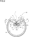
Fig. 2 is a cross-sectional view showing the speaker shown inFig. 1 ; -
Fig. 3 is a cross-sectional view showing a speaker according to a second embodiment of the present invention; -
Fig. 4 is a cross-sectional view showing a speaker according to a third embodiment of the present invention; -
Fig. 5 is a cross-sectional view showing the main sections of a speaker according to a fourth embodiment of the present invention; -
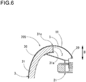
Fig. 6 is a cross-sectional view showing the main sections of a speaker according to a fifth embodiment of the present invention; -
Fig. 7 is a perspective view showing a speaker according to a sixth embodiment of the present invention; -
Fig. 8 is a perspective view showing a speaker according to a seventh embodiment of the present invention; -
Fig. 9 is a perspective view showing a speaker according to an eighth embodiment of the present invention; -
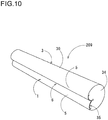
Fig. 10 is a perspective view showing a speaker according to a ninth embodiment of the present invention; -
Fig. 11 is a perspective view showing a speaker according to a tenth embodiment of the present invention; -
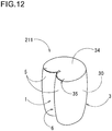
Fig. 12 is a perspective view showing a speaker according to an 11th embodiment of the present invention; -
Fig. 13 is a perspective view showing a speaker according to a 12th embodiment of the present invention; and -
Fig. 14 is a perspective view showing a speaker according to a 13th embodiment of the present invention. - Embodiments in which an electroacoustic transducer according to the present invention is applied to a speaker will be described below referring to the drawings.
-
Figs. 1 and2 show a speaker according to a first embodiment of the present invention. - A speaker (electroacoustic transducer) 100 according to this embodiment includes a vibrating
body 1 having one or more vertically splitcylindrical faces 5, an actuator (conversion section) 2 reciprocating the vibratingbody 1, and ahousing 3 for supporting the vibratingbody 1 and theactuator 2. - The vibrating
body 1 has a surface shape in which a pair of vertically splitcylindrical faces 5 is formed in parallel and avalley section 6 is formed between one side sections of the vertically splitcylindrical faces 5 adjacent to each other. The vibratingbody 1 shown as an example in the figure is formed of a pair ofcurved plates 11. The pair ofcurved plates 11 is formed so as to be curved along the vertically splitcylindrical faces 5, and the side sections of both thecurved plates 11 are integrally joined to each other to form thevalley section 6. - The above-mentioned vertically split
cylindrical face 5 is a face obtained by vertically splitting and cutting out part of a cylindrical face, and the above-mentioned side section of thecurved plate 11 is the side section of thecurved plate 11 in the curving direction of the vertically splitcylindrical face 5. Furthermore, in thevibrating body 1, the extending direction of thevalley section 6 is the vertical direction, and the direction orthogonal to this direction is the horizontal direction. - Moreover, the material of the vibrating
body 1 is not limited, and a material, such as synthetic resin, paper or metal, being generally used for the vibrating plate of a speaker can be used; hence, the vibrating body can be formed relatively easily by vacuum forming a film of synthetic resin, such as polypropylene or polyester. - Both the
curved plates 11 of the vibratingbody 1 are integrally formed by folding back a sheet of film at its central section serving as a joiningsection 13, whereby the joiningsection 13 having a V-shape or a U-shape in cross section is formed at the fold-back portion between both thecurved plates 11. Both thecurved plates 11 of the vibratingbody 1 can also be formed by bonding one side sections of thecurved plates 11 consisting of two sheets of film. - In addition, the vertically split
cylindrical face 5 of thecurved plate 11 is not necessarily required to have a single arc-shaped face, but it is possible to adopt faces, such as a face formed of continuous portions having a plurality of curvatures; a face having a constant curvature or a continuously changing curvature, for example, in the shape of a parabola or a spline curve in cross section in the circumferential direction (horizontal direction) of the vertically splitcylindrical face 5; a rectangular cylindrical face; and a face with a plurality of stair-like step sections. Hence, the vertically splitcylindrical face 5 of thecurved plate 11 is curved in one direction (in the circumferential direction of the vertically split cylindrical face 5: the horizontal direction) and is linear in the direction (the vertical direction of the vertically split cylindrical face 5) orthogonal to the one direction. Additionally, the pair ofcurved plates 11 is disposed in parallel in a state in which the convex directions thereof are oriented to the surface sides thereof in the same direction, and the side sections of thecurved plates 11 adjacent to each other are joined so as to have a common tangential direction at the joiningsection 13. Still further, thevalley section 6 is formed linearly between both thecurved plates 11 along the joiningsection 13 in the vertical direction of the vertically splitcylindrical faces 5. - Further, in order that uniform reproduction sound is obtained, both the
curved plates 11 are preferably formed so as to be symmetrical with respect to the tangential line L of thecurved plates 11 as shown inFig. 2 . However, the curved plates are not necessarily required to be linearly symmetrical. - The
actuator 2 is used to vibrate the valley section 12 of the vibratingbody 1 in its depth direction, and a voice coil motor is used for example. In this embodiment, theactuator 2 includes avoice coil 20 provided at the joiningsection 13 of thecurved plates 11 and amagnet mechanism 21 fixed to the supporting frame 32 of thehousing 3 as shown inFig. 2 . - The
voice coil 20 is formed of acoil 20b wound around acylindrical bobbin 20a, and the upper end of thevoice coil 20 is fixed to the lower edge of the joiningsection 13 via an adhesive or the like so that the joiningsection 13 of thecurved plates 11 is disposed in the radial direction of the coil. Furthermore, the outer circumferential section of thevoice coil 20 is supported by the supporting frame 32 via adamper 22, and thevoice coil 20 is provided so as to be reciprocable with respect to the supporting frame 32 in the axial direction of thevoice coil 20. A material being used for a general dynamic speaker can be applied to thedamper 22. - The
magnet mechanism 21 includes anannular magnet 23, a ring-shapedouter yoke 24 fixed to one of the poles of thismagnet 23 and aninner yoke 25 fixed to the other pole thereof. The tip end section of thepole section 25a provided at the center of theinner yoke 25 is disposed inside theouter yoke 24, whereby an annularmagnetic gap 26 is formed between theouter yoke 24 and theinner yoke 25, and the end section of thevoice coil 20 is inserted in thismagnetic gap 26. - The
housing 3 includes anexterior section 31 and the supporting frame 32 installed on theexterior section 31. - The
exterior section 31 is made of a material, such as an MDF (medium density fiberboard) or a particle board, and has a shape in which part of the nearly cylindrical shape thereof is cut out in the cylinder axis direction (the vertical direction inFig. 1 ) thereof. Inside theopening groove section 31a having been cut out as described above, the supporting frame 32 is installed so as to straddle theopening groove section 31 a. Furthermore, aspace section 33 is formed in the region enclosed with theexterior section 31 and the vibratingbody 1. The material of theexterior section 31 is not limited to the above-mentioned materials, and other materials may be used, provided that the materials are used for the housings of speakers. - At both the end sections of the
space section 33 in the cylinder axis direction (the vertical direction) thereof, a pair ofend plates 34 is provided to close both the ends of thespace section 33 as shown inFig. 1 . Each of theend plates 34 is disposed such that aslight clearance 35 is provided between the end plate and the vibratingbody 1 so as not to hinder the reciprocal movement of the vibratingbody 1. A member made of a porous material (sponge material) or the like not affecting the reciprocal movement of the vibratingbody 1 may be inserted into thisclearance 35 to close theclearance 35. - The supporting frame 32 is formed of a metallic material, for example; and at the
opening groove section 31 a of theexterior section 31, the supporting frame 32 includes theoutside frame sections 32a fixed to the end sections of the inner circumferential face of theexterior section 31, theinclined plate sections 32b extending inward in the radial direction from theoutside frame sections 32a, and theinside frame sections 32c formed at the lower ends of theinclined plate sections 32b; and themagnet mechanism 21 is installed on theinside frame sections 32c. - Furthermore, at the
opening groove section 31 a of theexterior section 31, the side sections of both thecurved plates 11 of the vibrating body 1 (the side sections of the vertically split cylindrical faces 5) on the opposite side of the joiningsection 13 are fixed to the end sections (fixingsections 31b) of the outer circumferential face of theexterior section 31. - In addition, the vibrating
body 1 is provided so as to be extended beyond the side sections of the curved plates 11 (the side sections of the vertically split cylindrical faces 5) on the opposite side of the joiningsection 13 in the curving direction of both thecurved plates 11. In other words, each of thecurved plates 11 of the vibratingbody 1 is extended beyond the fixingsection 31 b of theexterior section 31 to the outer circumferential face (the surface of the housing 3) of theexterior section 31 in the direction (indicated by arrow A inFig. 2 ) to the side section of the vertically splitcylindrical face 5. The vibratingbody 1 of thespeaker 100 according to this embodiment is provided so as to entirely surround the outer circumferential face of theexterior section 31 of the housing 3 (the surface of the housing 3) in the directions to the side sections of the vertically splitcylindrical faces 5, and the vertically splitcylindrical faces 5 of the vibratingbody 1 and theouter face 30 of thehousing 3 are made of the same material and integrally formed. Hence, the vertically splitcylindrical faces 5 of the vibratingbody 1 and theouter face 30 of thehousing 3 are formed into a continuous shape in the directions to the side sections of the vertically splitcylindrical faces 5, whereby the cross section of the speaker is formed into a heart shape as shown inFig. 2 . - In the
speaker 100 configured as described above, the side sections of both thecurved plates 11 of the vibrating body 1 (the side sections of the vertically split cylindrical faces 5) on the opposite sides of the joiningsection 13 are fixed to the fixingsections 31 b (the end sections of theopening groove section 31 a) of theexterior section 31 of thehousing 3 as described above; on the other hand, the joiningsection 13 at which the side sections of both thecurved plates 11 adjacent to each other are joined is provided so as to be vibrated by theactuator 2. Hence, when the drive current corresponding to a sound signal flows through thevoice coil 20 of theactuator 2 fixed to the vibratingbody 1, the drive force corresponding to the drive current is exerted to thevoice coil 20 by the change in magnetic flux caused by the drive current and the magnetic field inside themagnetic gap 26, thereby vibrating thevoice coil 20 in the direction orthogonal to the magnetic field (in the axial direction of thevoice coil 20, that is, in the vertical direction indicated by arrows inFig. 2 ). Hence, the vibratingbody 1 connected to thevoice coil 20 is vibrated in the depth direction of thevalley section 6, and reproduction sound is radiated from the surface of the vibratingbody 1. - Moreover, in the
speaker 100, the vertically splitcylindrical faces 5 of the vibratingbody 1 and theouter face 30 of thehousing 3, forming the external appearance of the speaker, are made of the same material, integrated and formed into a continuous shape in the directions to the side sections of the vertically splitcylindrical faces 5, whereby the vibratingbody 1 and thehousing 3 can have design with a smooth integral feeling so as not to be distinguished from each other in appearance and can exhibit excellent design property. - Since the vertically split
cylindrical faces 5 of the vibratingbody 1 and theouter face 30 of thehousing 3 are formed into the continuous shape, unwanted diffracted waves can be prevented from being generated from the connection portions between the vertically splitcylindrical faces 5 and theouter face 30 of thehousing 3. Since theouter face 30 of thehousing 3 is formed into a curved face, diffracted waves can be suppressed from being generated from thehousing 3. Consequently, the directional characteristics and frequency characteristics of the sound radiated from thespeaker 100 can be improved, whereby exhibit excellent acoustic characteristics can be exhibited. - Further, since the inner circumferential face of the
exterior section 31 of thehousing 3 is formed into a curved face, the generation of standing waves inside thehousing 3 is suppressed, whereby the frequency characteristics of the sound radiated from the speaker can also be improved. - Furthermore, since the vertically split
cylindrical faces 5 of the vibratingbody 1 and theouter face 30 of thehousing 3 are made of the same material as in thespeaker 100 according to this Embodiment, the vertically splitcylindrical faces 5 of the vibratingbody 1 and theouter face 30 of thehousing 3 can be formed into a smooth shape having no joint, whereby the integral feeling of the external appearance of the speaker can be further improved. - In the
speaker 100 according to this embodiment, theexterior section 31 of thehousing 3 is formed into a heart shape in cross section and theouter face 30 is formed only of a curved face; however, thehousing 3 is not limited to have this configuration. As in aspeaker 202 according to a second embodiment, shown inFig. 3 , and aspeaker 203 according to a third embodiment, shown inFig. 4 , even in the case that part of theexterior section 31 of thehousing 3 is formed into a flat face, since the vertically splitcylindrical faces 5 of the vibratingbody 1 and theouter face 30 of thehousing 3 are made of the same material, the integral feeling of the external appearance of the speaker can be improved. - Moreover, the vertically split
cylindrical faces 5 of the vibratingbody 1 and theouter face 30 of thehousing 3 are not necessarily required to be made of the same material, provided that they are formed into a continuous shape; however, in the case that they are made of the same material as in this embodiment, the effect of higher design property and sound property can be exhibited. - In the
speaker 100 according to this embodiment, the vibratingbody 1 is extended to theouter face 30 of thehousing 3 in the directions to the side sections of the vertically splitcylindrical faces 5 and provided so as to entirely surround theouter face 30 of the housing 3 (the surface of the housing 3); however, the necessity for ensuring the integral feeling of the external appearance is low at the portion of the speaker that is not visible to the listener when the speaker is used, such as the rear face portion of the speaker, because the portion hardly influences the design property of the speaker. For this reason, the vibratingbody 1 may merely be extended to at least the front face side of thehousing 3 in the directions to the side sections of the vertically splitcylindrical faces 5, and the vibrating body is not required to cover the rear face side of thespeaker 100. - Further, since the upper and
lower end plates 34 of thehousing 3 are each formed of a flat face in thespeaker 100, a line array speaker can be structured in which theend plates 34 of a plurality ofspeakers 100 are mutually connected so that thespeakers 100 are arranged continuously in the cylinder axis direction (the vertical direction). In this case, the respective vibratingbodies 1 can be disposed continuously so that clearances are almost eliminated among them by aligning thevalley sections 6 of the respective vibratingbodies 1 of the plurality ofspeakers 100 in the vertical direction. With this configuration, since the plural pairs of vertically splitcylindrical faces 5 connected continuously function as a pair of vertically split cylindrical faces having a huge length, wide directional characteristics are obtained in the left-right direction while limited directional characteristics are obtained in the vertical direction. Consequently, it is possible to provide a speaker capable of radiating sound only to a desired area. -
Figs. 5 to 14 show speakers according to other embodiments. In these embodiments, since the components of the vibrating body and others are the same as those according to the first embodiment, the components common to those according to the first embodiment are designated by the same numerals in the respective figures and their descriptions are omitted. - A
speaker 204 according to a fourth embodiment, shown inFig. 5 , is configured such that the vertically splitcylindrical faces 5 of the vibratingbody 1 and theouter face 30 of thehousing 3 are provided as separate members; however, the side sections of the vertically splitcylindrical faces 5 of the vibratingbody 1 and theconnection sections 31c at the end sections of theouter face 30 of thehousing 3 connected to the side sections of the vertically splitcylindrical faces 5 are formed so as to be flush with each other, thereby being smoothly connected so that their tangential lines become continuous. Since the side sections of the vertically splitcylindrical faces 5 of the vibratingbody 1 and theconnection sections 31 c of theouter face 30 of thehousing 3 are formed into the shape so that their surfaces are flush with each other, the vertically splitcylindrical faces 5 of the vibratingbody 1 and theconnection sections 31 c of theouter face 30 can have design with an integral feeling and can exhibit excellent design property even in the case that they are not made of the same material. - A
speaker 205 according to a fifth embodiment, shown inFig. 6 , is configured such that edge sections 7 for supporting the vibratingbody 1 so that the vibratingbody 1 can vibrate reciprocally in the depth direction (indicated by arrows B inFig. 4 ) are provided on the back faces of the side sections of the vertically splitcylindrical faces 5 in addition to the configuration in which the vertically splitcylindrical faces 5 of the vibratingbody 1 and theouter face 30 of thehousing 3 are formed as separate members according to the fourth embodiment described above. Since the side sections of thecurved plates 11 of the vibratingbody 1 are supported by the edge sections 7 in this case, the vibratingbody 1 entirely vibrates uniformly, whereby the vibration due to the so-called piston motion can be performed. Hence, as in a dynamic speaker, thespeaker 205 can reproduce sound having high sound pressure even in the low frequency band, whereby the reproduction frequency thereof can be expanded to the low frequency band. Also in thespeaker 205 according to the fifth embodiment, the side sections of the vertically splitcylindrical faces 5 and theconnection sections 31 c of theouter face 30 are formed so as to be flush with each other (the surfaces of the side sections of the vertically splitcylindrical faces 5 are flush with the surfaces of theconnection sections 31 c of the outer face 30), whereby design property is not impaired and excellent design property can be exhibited. - A
speaker 206 according to a sixth embodiment, shown inFig. 7 , is configured such that two vibratingbodies 1 are provided, aflat section 36 is disposed between the two vibratingbodies 1, and the two vibratingbodies 1 are disposed side by side in the left-right direction via theflat section 36 so that the extending directions of thevalley sections 6 thereof are parallel with each other. Furthermore, both theside sections 37 of thehousing 3 have semi-cylindrical outer faces extended in the directions from the side sections of the vertically splitcylindrical faces 5, and theouter face 30 of thehousing 3 including both theside sections 37 and theflat section 36 and the vertically splitcylindrical faces 5 of the two vibratingbodies 1 are made of the same material and integrally formed. As described above, the vibratingbodies 1 are provided so as to be extended to the surface ofhousing 3 in the directions to the side sections of the vertically splitcylindrical faces 5 and so as to entirely surround the surface of thehousing 3. Also in thespeaker 206 having the plurality of vibratingbodies 1 as described above, the vertically splitcylindrical faces 5 of the vibratingbodies 1 and theouter face 30 of thehousing 3 can be formed into a smooth shape having no joint, whereby the integral feeling of the external appearance of the speaker can be improved. - Moreover, in this
speaker 206, an actuator, not shown, for reciprocating each vibratingbody 1 is provided in the bottom section of thevalley section 6 of each vibratingbody 1. Hence, thespeaker 206 can process the audio signals of two channels using the vibratingbodies 1. What's more, a configuration in which three vibratingbodies 1 are provided can also be obtained as in aspeaker 207 according to a seventh embodiment, shown inFig. 8 , by additionally disposing a vibratingbody 1 for the audio signal (for example, the center audio signal) of a third channel on theflat section 36 between the two vibratingbodies 1. Thespeaker 207 is configured such that the three vibratingbodies 1 are disposed side by side in the left-right direction via theflat sections 36 so that the extending directions of thevalleys 6 thereof are parallel with one another. Furthermore, both theside sections 37 of thehousing 3 having semi-cylindrical outer faces extended in the directions from the side sections of the vertically splitcylindrical faces 5, and theouter face 30 of thehousing 3 including both theside sections 37 and theflat sections 36 and the vertically splitcylindrical faces 5 of the three vibratingbodies 1 are made of the same material and integrally formed. As described above, also in thisspeaker 207, as in thespeaker 206 according to the sixth embodiment, the vibratingbodies 1 are provided so as to be extended to the surface of thehousing 3 in the directions to the side sections of the vertically splitcylindrical faces 5 and so as to entirely surround the surface of thehousing 3. - Also in the
speaker 206 according to the sixth embodiment and thespeaker 207 according to the seventh embodiment, the vertically splitcylindrical faces 5 of the vibratingbodies 1 and theouter face 30 of thehousing 3, forming the external appearance of the speaker, are formed into a continuous shape in the directions to the side sections of the vertically split cylindrical faces 5. Consequently, as in thespeaker 100 according to the first embodiment, the vibratingbodies 1 and thehousing 3 can have design with a smooth integral feeling so as not to be distinguished from each other in appearance. - Furthermore, with combinations of a plurality of vibrating
bodies 1 as in thespeaker 206 according to the sixth embodiment and thespeaker 207 according to the seventh embodiment, stereo 2-channel audio signals, 2.1-channel audio signals (stereo 2-channel audio signals and 0.1-channel audio signal for bass sound) or 3-channel audio signals (stereo 2-channel audio signals and 1-channel audio signal for center) can be reproduced using a single speaker. -
Fig. 9 shows aspeaker 208 according to an eighth embodiment. In thisspeaker 208, the front-sideouter face 30 of thehousing 3 is formed only of a flat face, the vertically splitcylindrical faces 5 of the vibratingbody 1, forming the external appearance of the speaker on the front side, are extended in the directions to the side sections thereof, whereby the vertically splitcylindrical faces 5 and theouter face 30 of thehousing 3 are made of the same material and formed into a continuous shape. - The
speaker 208 in which the front side of thehousing 3 is formed only of a flat face as described above is incorporated so as to constitute part of the exterior (indicated by alternate long and two short lines inFig. 9 ) of another product having speakers as shown inFig. 9 , whereby the vibratingbody 1 and thehousing 3 are integrated with the above-mentioned product so as not to be distinguished from the product in appearance, and the design of the product with a smooth appearance can be obtained. -
Fig. 10 shows aspeaker 209 according to a ninth embodiment. In thisspeaker 209, the vibratingbody 1 thereof is made longer than that of thespeaker 100 according to the first embodiment in the extending direction of thevalley section 6; and although thespeaker 100 according to the first embodiment is used in a state in which the extending direction of thevalley section 6 is disposed in the vertical direction, thespeaker 209 according to the ninth embodiment is used in a state in which the extending direction of thevalley section 6 is disposed in the left-right direction. - Furthermore, also in this
speaker 209, as in thespeaker 100 according to the first embodiment, the vibratingbody 1 is provided so as to be extended to theouter face 30 of thehousing 3 in the directions to the side sections of the vertically splitcylindrical faces 5 and so as to entirely surround the surface of thehousing 3, and the vertically splitcylindrical faces 5 and theouter face 30 are formed of the same material. Moreover, thespeaker 209 is provided with a plurality (for example, two) of actuators, not shown, for reciprocating the vibratingbody 1 at intervals in the extending direction of thevalley section 6. Hence, the vibratingbody 1 can be entirely vibrated uniformly in the extending direction of thevalley section 6, whereby the speaker can provide uniform sound in an area wider than the height of thespeaker 209 in the vertical direction orthogonal to the extending direction of thevalley section 6, and on the other hand, in an area limited to the width of thespeaker 209 in the left-right direction along the extending direction of thevalley section 6. - As in a
speaker 210 according to a tenth embodiment, shown inFig. 11 , thespeaker 210 can be entirely formed into a curved shape by pushing forward the central section of thevalley section 6 of the vertically splitcylindrical faces 5 in the extending direction thereof. Consequently, in thespeaker 210, thevalley section 6 is also formed into a curved shape by pressing forward the central section thereof in the extending direction thereof. - In addition, as shown in
Fig. 11 , thespeaker 210 can be united with a thin box-like rack 8 (indicated by alternate long and two short lines in the figure) on the rear side of thespeaker 210. Furthermore, as in thespeaker 209 according to the ninth embodiment, thespeaker 210 is used in a state in which the extending direction of thevalley section 6 is oriented in the left-right direction. - In this
speaker 210, as in thespeaker 100 according to the first embodiment, the vibratingbody 1 is provided so as to be extended to theouter face 30 of thehousing 3 in the directions to the side sections of the vertically splitcylindrical faces 5 and so as to entirely surround the surface of thehousing 3, and the vertically splitcylindrical faces 5 and theouter face 30 are formed of the same material. Moreover, the cross-sectional shape of the speaker in the directions to the side sections of the vertically split cylindrical faces 5 (in the direction orthogonal to the extending direction of the valley section 6) is the same at any position, as in thespeaker 100 according to the first embodiment shown inFig. 2 . In addition, thespeaker 209 is formed into a curved shape by pushing forward the central sections of the vertically splitcylindrical faces 5, whereby the speaker can provide uniform sound in an area wider than the height of thespeaker 209 in the vertical direction orthogonal to the extending direction of thevalley section 6 and in an area wider than the width of thespeaker 209 in the left-right direction along the extending direction of thevalley section 6. - Furthermore, as in a
speaker 211 according to an 11th embodiment, shown inFig. 12 , the speaker can be formed into a barrel shape as a whole by using a configuration in which the vertically splitcylindrical faces 5 of the vibratingbody 1 and theouter face 30 of thehousing 3 are pushed forward at the central section of thevalley section 6 in the extending direction thereof and are swollen in the left-right direction. In this case, the cross-sectional shape of the speaker in the directions to the side sections of the vertically split cylindrical faces 5 becomes gradually larger in the directions from both the side sections of thevalley section 6 to the central section. Moreover, as in thespeaker 100 according to the first embodiment, thespeaker 211 is used in a state in which the extending direction of thevalley section 6 is oriented in the vertical direction. - Also in this
speaker 211, as in thespeaker 100 according to the first embodiment, the vibratingbody 1 is provided so as to be extended to theouter face 30 of thehousing 3 in the directions to the side sections of the vertically splitcylindrical faces 5 and so as to entirely surround the surface of thehousing 3, and the vertically splitcylindrical faces 5 and theouter face 30 are formed of the same material. Moreover, thespeaker 211 is formed into a curved shape not only in the directions to the side sections of the vertically splitcylindrical faces 5 but also in the extending direction of thevalley section 6 by using a configuration in which the vertically splitcylindrical faces 5 of the vibratingbody 1 are pushed forward at the central section of thevalley section 6 in the extending direction thereof and are swollen in the left-right direction. Consequently, the speaker can provide uniform sound in an area wider than the height of thespeaker 211 in the vertical direction along the extending direction of the valley section and in an area wider than the width of thespeaker 211 in the left-right direction orthogonal to the extending direction of thevalley section 6. - As in a
speaker 212 according to a 12th embodiment, shown inFig. 13 , the vibratingbody 1 is formed into a continuously curved shape by mutually joining the side sections of plural pairs (for example, two pairs as shown in the figure) of vertically splitcylindrical faces 5, whereby the plural pairs of vertically splitcylindrical faces 5 constituting the vibratingbody 1 are united in the directions to the side sections of the vertically split cylindrical faces, and a speaker outputting audio signals of a plurality of channels (two channels in the configuration shown in the figure) can be configured. - In this
speaker 212, unlike thespeaker 206 according to the sixth embodiment and thespeaker 208 according to the seventh embodiment, the side sections of the vertically splitcylindrical faces 5 adjacent to each other are joined without providing theflat section 36 between the side sections of the plural pairs of vertically splitcylindrical faces 5, whereby the vertically splitcylindrical faces 5 are united and the vibratingbody 1 having a plurality of curved shapes is formed. Furthermore, the vibratingbody 1 is provided so as to be extended to theouter face 30 of thehousing 3 in the directions to the side sections of the vertically splitcylindrical faces 5 and so as to entirely surround the surface of thehousing 3, whereby the vertically splitcylindrical faces 5 and theouter face 30 are formed of the same material. - On the other hand, unlike the case in which the vibrating
body 1 is formed of one or more pairs of vertically splitcylindrical faces 5 as in thespeaker 100 according to the first embodiment (seeFig. 1 ) or thespeaker 212 according to the 12th embodiment (seeFig. 12 ), the vibratingbody 1 can be formed using a single vertically splitcylindrical face 5 as in aspeaker 213 according to a 13th embodiment, shown inFig. 14 . Also in thisspeaker 213, the vibratingbody 1 is provided so as to be extended in the directions to the side sections of the vertically splitcylindrical face 5 and so as to entirely surround the surface of thehousing 3, whereby the vertically splitcylindrical face 5 and theouter face 30 are formed of the same material. - Also in the
speakers 210 to 213 having the above-mentioned various configurations, the vertically splitcylindrical faces 5 of the vibratingbodies 1 and theouter face 30 of thehousing 3, forming the external appearance of the speaker, are formed into a continuous shape in the directions to the side sections of the vertically splitcylindrical faces 5, whereby the vibratingbody 1 and thehousing 3 can have design with a smooth integral feeling so as not to be distinguished from each other in appearance. - The present invention is not limited to the above-mentioned embodiments but can be modified variously within the scope not departing from the gist of the present invention.
- For example, although the voice coil motor is applied as a conversion section for reciprocating the vibrating body, a piezoelectric element or the like may be used instead of the voice coil motor.
- Furthermore, although the present invention is applied to speakers in all the above-mentioned embodiments, the present invention can also be applied to microphones. In the case that the present invention is applied to speakers, a conversion section, such as a voice coil motor, converts an electrical signal based on an audio signal into the vibration of a vibrating body; and in the case that the present invention is applied to microphones, a voice coil motor or the like can also be used as a conversion section, and the conversion section in this case converts the vibration of the vibrating body that vibrates by receiving a sound wave into an electrical signal.
- Although the speaker according to each embodiment of the present invention can be used singly as a speaker, the speaker can also be used, for example, as a piece of interior furniture by using a transmittable resin as the material constituting the vibrating body and the outer face of the housing (in the case of the configuration shown in
Fig. 2 , it is preferable that a transmittable resin should be used as the material of the vibratingbody 1 and theouter face 30 of thehousing 3 and as the material of the exterior section 31) and by illuminating the inside of the housing. Furthermore, the speaker can also be applied so as to constitute part of the exterior of another product having speakers, such as an electronic keyboard instrument. - The characteristics of the electroacoustic transducer according to the embodiments of the present invention described above will be briefly summarized and listed as described below.
- An electroacoustic transducer according to the present invention includes a vibrating body having one or more vertically split cylindrical faces; a housing having fixing sections that fix side sections of the vertically split cylindrical faces of the vibrating body; and a conversion section that converts a signal into vibration of the vibrating body, wherein the vibrating body is extended to a surface of the housing in directions to the side sections of the vertically split cylindrical faces instead of being extended to the fixing sections.
- Since the vibrating body is provided so as to be extended to the surface of the housing in the directions to the side sections of the vertically split cylindrical faces, the vertically split cylindrical faces and the outer face of the housing, forming the external appearance of the electroacoustic transducer, can be made of the same material, integrated and formed into a shape having no joint. Hence, the vibrating body and the housing can have design with an integral feeling so as not to be distinguished from each other in appearance and can exhibit excellent design property.
- Furthermore, in the case that the electroacoustic transducer according to the present invention is applied to a speaker, since the vertically split cylindrical faces of the vibrating body and the outer face of the housing are formed into the continuous shape, unwanted diffracted waves can be prevented from being generated from the connection portions between the vertically split cylindrical faces and the outer face of the housing. Consequently, the directional characteristics and frequency characteristics of the sound radiated from the speaker can be improved, whereby excellent acoustic characteristics can be exhibited.
- Moreover, in the electroacoustic transducer according to the present invention, it is preferable that the vibrating body may be provided so as to entirely surround the surface of the housing in the directions to the side sections of the vertically split cylindrical faces (formed so as to surround the entire circumference of the surface of the housing).
- In the electroacoustic transducer according to the present invention, it is preferable that the front face side of the housing may be formed into a flat face, that the one or more vertically split cylindrical faces may be a pair of vertically split cylindrical faces formed in parallel, that one side sections of the pair of vertically split cylindrical faces may be connected so as to form a valley section, and that the other side sections of the pair of vertically split cylindrical faces may be extended to the surface of the housing along the flat face of the housing.
- An electroacoustic transducer according to the present invention includes a vibrating body having one or more vertically split cylindrical faces; a housing having connection sections that are joined to side sections of the vertically split cylindrical faces of the vibrating body; and a conversion section that converts an electrical signal into vibration of the vibrating body, wherein the side sections of the vertically split cylindrical faces are formed so as to be flush with the connection sections of the housing.
- Even in the case that the vertically split cylindrical faces of the vibrating body and the outer face of the housing are formed as separate members, design with an integral feeling can be obtained and excellent design property can be exhibited by making these faces flush with each other.
- Further, in the electroacoustic transducer according to the present invention, for example, it is preferable that the one or more vertically split cylindrical faces may be a pair of vertically split cylindrical faces formed in parallel, and that a valley section may be formed between the side sections of the vertically split cylindrical faces which are adjacent to each other.
- Further, in the electroacoustic transducer according to the present invention, it is preferable that the pair of vertically split cylindrical faces and the housing may be formed as separate members and that the side sections of the pair of vertically split cylindrical faces may be supported by edge sections formed on back faces of the connection sections of the housing so as to enable the vibrating body to be reciprocated in a depth direction of the valley section.
- Although the present invention has been described in detail with reference to specific embodiments, it is obvious to those skilled in the art that various changes and modifications can be made without departing from the spirit and scope of the present invention.
- The present application is based on
Japanese Patent Application (patent application 2014-132522) filed on June 27, 2014 - The present invention can provide an electroacoustic transducer being excellent in acoustic characteristics.
-
- 1
- vibrating body
- 2
- actuator (conversion section)
- 3
- housing
- 5
- vertically split cylindrical face
- 6
- valley section
- 7
- edge section
- 8
- rack
- 11
- curved plate
- 13
- joining section
- 20
- voice coil
- 20a
- bobbin
- 20b
- coil
- 21
- magnet mechanism
- 22
- damper
- 23
- magnet
- 24
- outer yoke
- 25
- inner yoke
- 25a
- pole section
- 26
- magnetic gap
- 30
- outer face
- 31
- exterior section
- 31a
- opening groove section
- 31b
- fixing section
- 31c
- connection section
- 32
- supporting frame
- 32a
- outside frame section
- 32b
- inclined plate section
- 32c
- inside frame section
- 33
- space section
- 34
- end plate
- 35
- clearance
- 36
- flat section
- 37
- both side sections
- 100
- speaker
Claims (6)
- An electroacoustic transducer comprising:a vibrating body having one or more vertically split cylindrical faces;a housing having fixing sections that fix side sections of the vertically split cylindrical faces of the vibrating body; anda conversion section that converts an electrical signal into vibration of the vibrating body,wherein the vibrating body is extended to a surface of the housing in directions to the side sections of the vertically split cylindrical faces.
- The electroacoustic transducer according to claim 1, wherein the vibrating body is provided so as to entirely surround the surface of the housing in the directions to the side sections of the vertically split cylindrical faces.
- An electroacoustic transducer comprising:a vibrating body having one or more vertically split cylindrical faces;a housing having connection sections that are joined to side sections of the vertically split cylindrical faces of the vibrating body; anda conversion section that converts an electrical signal into vibration of the vibrating body,wherein the side sections of the vertically split cylindrical faces are formed so as to be flush with the connection sections of the housing.
- The electroacoustic transducer according to any one of claims 1 to 3, wherein the one or more vertically split cylindrical faces are a pair of vertically split cylindrical faces formed in parallel, and a valley section is formed between the vertically split cylindrical faces which are adjacent to each other.
- The electroacoustic transducer according to claim 4, wherein the pair of vertically split cylindrical faces and the housing are formed as separate members; and
wherein side sections of the pair of vertically split cylindrical faces are supported by edge sections formed on back faces of the connection sections of the housing so as to enable the vibrating body to be reciprocated in a depth direction of the valley section. - The electroacoustic transducer according to claim 1, wherein a front face side of the housing is formed into a flat face;
wherein the one or more vertically split cylindrical faces are a pair of vertically split cylindrical faces formed in parallel;
wherein one side sections of the pair of vertically split cylindrical faces are connected so as to form a valley section; and
wherein the other side sections of the pair of vertically split cylindrical faces are extended to a surface of the housing along the flat face of the housing.
Applications Claiming Priority (2)
| Application Number | Priority Date | Filing Date | Title |
|---|---|---|---|
| JP2014132522A JP6435662B2 (en) | 2014-06-27 | 2014-06-27 | Electroacoustic transducer |
| PCT/JP2015/068582 WO2015199236A1 (en) | 2014-06-27 | 2015-06-26 | Electroacoustic transducer |
Publications (2)
| Publication Number | Publication Date |
|---|---|
| EP3163907A1 true EP3163907A1 (en) | 2017-05-03 |
| EP3163907A4 EP3163907A4 (en) | 2018-02-21 |
Family
ID=54938313
Family Applications (1)
| Application Number | Title | Priority Date | Filing Date |
|---|---|---|---|
| EP15810941.3A Withdrawn EP3163907A4 (en) | 2014-06-27 | 2015-06-26 | Electroacoustic transducer |
Country Status (5)
| Country | Link |
|---|---|
| US (1) | US10123122B2 (en) |
| EP (1) | EP3163907A4 (en) |
| JP (1) | JP6435662B2 (en) |
| CN (1) | CN106465016A (en) |
| WO (1) | WO2015199236A1 (en) |
Cited By (1)
| Publication number | Priority date | Publication date | Assignee | Title |
|---|---|---|---|---|
| US11356760B2 (en) | 2018-03-30 | 2022-06-07 | Sony Corporation | Audio device and audio reproduction apparatus |
Families Citing this family (5)
| Publication number | Priority date | Publication date | Assignee | Title |
|---|---|---|---|---|
| TWM524028U (en) * | 2016-03-25 | 2016-06-11 | Jetvox Acoustic Corp | Earphone device with airflow collecting tube |
| US10785560B2 (en) * | 2016-05-09 | 2020-09-22 | Samsung Electronics Co., Ltd. | Waveguide for a height channel in a speaker |
| JP6206994B1 (en) * | 2016-07-06 | 2017-10-04 | 篤志 倉田 | Speaker device |
| WO2018012181A1 (en) * | 2016-07-14 | 2018-01-18 | ソニー株式会社 | Speaker device |
| US20240121559A1 (en) * | 2022-10-07 | 2024-04-11 | Apple Inc. | Cylindrical mems structures for audio components |
Family Cites Families (18)
| Publication number | Priority date | Publication date | Assignee | Title |
|---|---|---|---|---|
| US1866090A (en) * | 1926-05-22 | 1932-07-05 | Forest Lee De | Sound reproducing device |
| US1821469A (en) * | 1928-08-03 | 1931-09-01 | Chester W Hicks | Sound amplifier |
| US4276449A (en) * | 1978-06-01 | 1981-06-30 | Tadashi Sawafuji | Speaker or microphone having corrugated diaphragm with conductors thereon |
| JPS59114686U (en) | 1983-03-26 | 1984-08-02 | 日本ビクター株式会社 | Lighting device with speaker |
| DE3620557A1 (en) * | 1986-06-19 | 1987-12-23 | Reinhardt Fischer | Electroacoustic transducer |
| US4903308A (en) * | 1988-02-10 | 1990-02-20 | Linaeum Corporation | Audio transducer with controlled flexibility diaphragm |
| US5450497A (en) * | 1992-05-11 | 1995-09-12 | Linaeum Corporation | Audio transducer improvements |
| WO1994014294A1 (en) * | 1992-12-08 | 1994-06-23 | Linaeum Corporation | Audio transducer with flexible foam enclosure |
| US5652801A (en) * | 1994-05-02 | 1997-07-29 | Aura Systems, Inc. | Resonance damper for piezoelectric transducer |
| JP3521319B2 (en) | 1994-09-29 | 2004-04-19 | フオスター電機株式会社 | Speaker |
| JP2002078079A (en) * | 2000-08-24 | 2002-03-15 | Pioneer Electronic Corp | Electroacoustic transducer |
| JP4603972B2 (en) * | 2005-12-21 | 2010-12-22 | パイオニア株式会社 | Diaphragm for speaker device, speaker device, and mobile phone |
| JP4925892B2 (en) * | 2007-03-29 | 2012-05-09 | ビフレステック株式会社 | Speaker device |
| JP5191796B2 (en) | 2008-05-16 | 2013-05-08 | アルパイン株式会社 | Speaker |
| EP2514217B1 (en) * | 2009-12-17 | 2015-04-22 | Genelec OY | Drive unit mounting arrangement and loudspeaker |
| JP6048470B2 (en) * | 2013-10-22 | 2016-12-21 | ヤマハ株式会社 | Electroacoustic transducer |
| JP6048469B2 (en) * | 2013-10-22 | 2016-12-21 | ヤマハ株式会社 | Electroacoustic transducer |
| JP5668233B1 (en) * | 2014-03-26 | 2015-02-12 | 株式会社サウンドファン | Universal speaker |
-
2014
- 2014-06-27 JP JP2014132522A patent/JP6435662B2/en not_active Expired - Fee Related
-
2015
- 2015-06-26 CN CN201580035121.2A patent/CN106465016A/en active Pending
- 2015-06-26 WO PCT/JP2015/068582 patent/WO2015199236A1/en not_active Ceased
- 2015-06-26 EP EP15810941.3A patent/EP3163907A4/en not_active Withdrawn
-
2016
- 2016-12-23 US US15/389,485 patent/US10123122B2/en active Active
Cited By (1)
| Publication number | Priority date | Publication date | Assignee | Title |
|---|---|---|---|---|
| US11356760B2 (en) | 2018-03-30 | 2022-06-07 | Sony Corporation | Audio device and audio reproduction apparatus |
Also Published As
| Publication number | Publication date |
|---|---|
| US20170105072A1 (en) | 2017-04-13 |
| EP3163907A4 (en) | 2018-02-21 |
| CN106465016A (en) | 2017-02-22 |
| JP6435662B2 (en) | 2018-12-12 |
| WO2015199236A1 (en) | 2015-12-30 |
| JP2016012777A (en) | 2016-01-21 |
| US10123122B2 (en) | 2018-11-06 |
Similar Documents
| Publication | Publication Date | Title |
|---|---|---|
| US10123122B2 (en) | Electroacoustic transducer | |
| EP3145214A1 (en) | Electroacoustic transducer | |
| US9386377B2 (en) | Magnetic assembly and electro-acoustic transducer using same | |
| EP3322543B1 (en) | Vibrating actuator | |
| JP6048469B2 (en) | Electroacoustic transducer | |
| CN107079221B (en) | Electroacoustic transducer | |
| JP6394158B2 (en) | Electroacoustic transducer | |
| JP5337885B2 (en) | Speaker | |
| EP2866467B1 (en) | Electroacoustic transducer | |
| CN101888579B (en) | Multifunctional micro speaker | |
| US8532327B2 (en) | Diaphragm and speaker device provided with the same | |
| JP2009267779A (en) | Electromagnetic electro-acoustic transducer | |
| KR100676422B1 (en) | Multi-point driven multiway slim flat speaker system | |
| JP6065819B2 (en) | Electroacoustic transducer | |
| WO2023247017A1 (en) | Vibratory system comprising a vibratory panel with an acoustic black hole structure | |
| JP2009246739A (en) | Diaphragm and electro-acoustic transducer | |
| JP6065820B2 (en) | Electroacoustic transducer | |
| JP6187666B2 (en) | Electroacoustic transducer | |
| JP2016039550A (en) | Electro-acoustic transducer | |
| CN208190902U (en) | Minitype acoustic generator | |
| WO2016110992A1 (en) | Electroacoustic transducer | |
| WO2016110991A1 (en) | Electroacoustic transducer | |
| HK1247888B (en) | Vibrating actuator | |
| HK1058608B (en) | Low profile speaker and system |
Legal Events
| Date | Code | Title | Description |
|---|---|---|---|
| PUAI | Public reference made under article 153(3) epc to a published international application that has entered the european phase |
Free format text: ORIGINAL CODE: 0009012 |
|
| 17P | Request for examination filed |
Effective date: 20161223 |
|
| AK | Designated contracting states |
Kind code of ref document: A1 Designated state(s): AL AT BE BG CH CY CZ DE DK EE ES FI FR GB GR HR HU IE IS IT LI LT LU LV MC MK MT NL NO PL PT RO RS SE SI SK SM TR |
|
| AX | Request for extension of the european patent |
Extension state: BA ME |
|
| DAV | Request for validation of the european patent (deleted) | ||
| DAX | Request for extension of the european patent (deleted) | ||
| A4 | Supplementary search report drawn up and despatched |
Effective date: 20180123 |
|
| RIC1 | Information provided on ipc code assigned before grant |
Ipc: H04R 7/20 20060101ALI20180117BHEP Ipc: H04R 9/04 20060101ALI20180117BHEP Ipc: H04R 7/12 20060101AFI20180117BHEP |
|
| 17Q | First examination report despatched |
Effective date: 20190730 |
|
| STAA | Information on the status of an ep patent application or granted ep patent |
Free format text: STATUS: THE APPLICATION HAS BEEN WITHDRAWN |
|
| 18W | Application withdrawn |
Effective date: 20191204 |