EP3163756A1 - Portable device - Google Patents
Portable device Download PDFInfo
- Publication number
- EP3163756A1 EP3163756A1 EP16195477.1A EP16195477A EP3163756A1 EP 3163756 A1 EP3163756 A1 EP 3163756A1 EP 16195477 A EP16195477 A EP 16195477A EP 3163756 A1 EP3163756 A1 EP 3163756A1
- Authority
- EP
- European Patent Office
- Prior art keywords
- circuit board
- engaging portion
- protection cover
- battery holder
- extension
- Prior art date
- Legal status (The legal status is an assumption and is not a legal conclusion. Google has not performed a legal analysis and makes no representation as to the accuracy of the status listed.)
- Granted
Links
Images



Classifications
-
- H—ELECTRICITY
- H05—ELECTRIC TECHNIQUES NOT OTHERWISE PROVIDED FOR
- H05K—PRINTED CIRCUITS; CASINGS OR CONSTRUCTIONAL DETAILS OF ELECTRIC APPARATUS; MANUFACTURE OF ASSEMBLAGES OF ELECTRICAL COMPONENTS
- H05K5/00—Casings, cabinets or drawers for electric apparatus
- H05K5/0026—Casings, cabinets or drawers for electric apparatus provided with connectors and printed circuit boards [PCB], e.g. automotive electronic control units
- H05K5/0047—Casings, cabinets or drawers for electric apparatus provided with connectors and printed circuit boards [PCB], e.g. automotive electronic control units having a two-part housing enclosing a PCB
- H05K5/0052—Casings, cabinets or drawers for electric apparatus provided with connectors and printed circuit boards [PCB], e.g. automotive electronic control units having a two-part housing enclosing a PCB characterized by joining features of the housing parts
-
- G—PHYSICS
- G07—CHECKING-DEVICES
- G07C—TIME OR ATTENDANCE REGISTERS; REGISTERING OR INDICATING THE WORKING OF MACHINES; GENERATING RANDOM NUMBERS; VOTING OR LOTTERY APPARATUS; ARRANGEMENTS, SYSTEMS OR APPARATUS FOR CHECKING NOT PROVIDED FOR ELSEWHERE
- G07C9/00—Individual registration on entry or exit
- G07C9/00174—Electronically operated locks; Circuits therefor; Nonmechanical keys therefor, e.g. passive or active electrical keys or other data carriers without mechanical keys
- G07C9/00944—Details of construction or manufacture
-
- B—PERFORMING OPERATIONS; TRANSPORTING
- B60—VEHICLES IN GENERAL
- B60R—VEHICLES, VEHICLE FITTINGS, OR VEHICLE PARTS, NOT OTHERWISE PROVIDED FOR
- B60R25/00—Fittings or systems for preventing or indicating unauthorised use or theft of vehicles
- B60R25/20—Means to switch the anti-theft system on or off
- B60R25/24—Means to switch the anti-theft system on or off using electronic identifiers containing a code not memorised by the user
-
- H—ELECTRICITY
- H05—ELECTRIC TECHNIQUES NOT OTHERWISE PROVIDED FOR
- H05K—PRINTED CIRCUITS; CASINGS OR CONSTRUCTIONAL DETAILS OF ELECTRIC APPARATUS; MANUFACTURE OF ASSEMBLAGES OF ELECTRICAL COMPONENTS
- H05K5/00—Casings, cabinets or drawers for electric apparatus
- H05K5/0026—Casings, cabinets or drawers for electric apparatus provided with connectors and printed circuit boards [PCB], e.g. automotive electronic control units
- H05K5/0047—Casings, cabinets or drawers for electric apparatus provided with connectors and printed circuit boards [PCB], e.g. automotive electronic control units having a two-part housing enclosing a PCB
- H05K5/006—Casings, cabinets or drawers for electric apparatus provided with connectors and printed circuit boards [PCB], e.g. automotive electronic control units having a two-part housing enclosing a PCB characterized by features for holding the PCB within the housing
-
- H—ELECTRICITY
- H05—ELECTRIC TECHNIQUES NOT OTHERWISE PROVIDED FOR
- H05K—PRINTED CIRCUITS; CASINGS OR CONSTRUCTIONAL DETAILS OF ELECTRIC APPARATUS; MANUFACTURE OF ASSEMBLAGES OF ELECTRICAL COMPONENTS
- H05K5/00—Casings, cabinets or drawers for electric apparatus
- H05K5/10—Casings, cabinets or drawers for electric apparatus comprising several parts forming a closed casing
- H05K5/15—Casings, cabinets or drawers for electric apparatus comprising several parts forming a closed casing assembled by resilient members
-
- E—FIXED CONSTRUCTIONS
- E05—LOCKS; KEYS; WINDOW OR DOOR FITTINGS; SAFES
- E05B—LOCKS; ACCESSORIES THEREFOR; HANDCUFFS
- E05B19/00—Keys; Accessories therefor
- E05B19/0082—Keys or shanks being removably stored in a larger object, e.g. a remote control or a key fob
-
- G—PHYSICS
- G07—CHECKING-DEVICES
- G07C—TIME OR ATTENDANCE REGISTERS; REGISTERING OR INDICATING THE WORKING OF MACHINES; GENERATING RANDOM NUMBERS; VOTING OR LOTTERY APPARATUS; ARRANGEMENTS, SYSTEMS OR APPARATUS FOR CHECKING NOT PROVIDED FOR ELSEWHERE
- G07C9/00—Individual registration on entry or exit
- G07C9/00174—Electronically operated locks; Circuits therefor; Nonmechanical keys therefor, e.g. passive or active electrical keys or other data carriers without mechanical keys
- G07C2009/00968—Electronically operated locks; Circuits therefor; Nonmechanical keys therefor, e.g. passive or active electrical keys or other data carriers without mechanical keys shape of the data carrier
- G07C2009/00984—Electronically operated locks; Circuits therefor; Nonmechanical keys therefor, e.g. passive or active electrical keys or other data carriers without mechanical keys shape of the data carrier fob
-
- G—PHYSICS
- G07—CHECKING-DEVICES
- G07C—TIME OR ATTENDANCE REGISTERS; REGISTERING OR INDICATING THE WORKING OF MACHINES; GENERATING RANDOM NUMBERS; VOTING OR LOTTERY APPARATUS; ARRANGEMENTS, SYSTEMS OR APPARATUS FOR CHECKING NOT PROVIDED FOR ELSEWHERE
- G07C9/00—Individual registration on entry or exit
- G07C9/00174—Electronically operated locks; Circuits therefor; Nonmechanical keys therefor, e.g. passive or active electrical keys or other data carriers without mechanical keys
- G07C9/00309—Electronically operated locks; Circuits therefor; Nonmechanical keys therefor, e.g. passive or active electrical keys or other data carriers without mechanical keys operated with bidirectional data transmission between data carrier and locks
Definitions
- This disclosure relates to a portable device.
- a portable device for operating the vehicle is used in an electronic key system.
- Japanese Laid-Open Patent Publication No. 2013-19224 describes a portable device including electronic components such as a circuit board and a battery. The feature of the portable device is in how the circuit board is accommodated in the portable device.
- the circuit board which includes a surface on which circuit elements are mounted, is held between a protection cover and a battery holder.
- the protection cover includes projections, each including an engagement hook.
- the engagement hook of the protection cover is snap-fitted to a corresponding groove located in an outer wall of the battery holder. This couples the protection cover to the battery holder.
- the engagement hook extends from the corresponding projection of the protection cover toward the circuit board.
- the protection cover includes a guard plate at the rear of each projection (engagement hook). The guard plate covers the projection so that the engagement hook cannot be seen from the exterior when the protection cover is coupled to the battery holder.
- each guard plate will have to be located at a further inner position on the protection cover.
- the projection (particularly, engagement hook) of the protection cover will partially occupy and reduce the size of the circuit area for the circuit elements and the wires.
- each projection (engagement hook) and the corresponding guard plate will have to be located at a further outer position on the protection cover. This will enlarge the protection cover and the battery holder. Therefore, there is a trade-off between the miniaturization of the protection cover and the battery holder and the enlargement of the circuit area for the circuit elements and the wires.
- One embodiment is a portable device that includes a circuit board on which a circuit element is mounted, a first member, and a second member.
- the circuit board is held and fastened between the first member and the second member.
- the first member includes a wall that extends toward the second member from the first member.
- the second member includes an engaging portion.
- the engaging portion includes an extension that extends toward the first member from the second member and a hook that projects from the extension.
- the circuit board includes an end surface that defines an edge of the circuit board.
- the extension is opposed to the end surface of the circuit board.
- the hook projects from the extension in a direction that extends along the end surface of the circuit board.
- the portable device further includes an engaged portion located along an inner side of the wall. The engaged portion engages the engaging portion to fasten the first member to the second member.
- the portable device is reduced in size without reducing the space of the circuit area.
- the portable device of the first embodiment is, for example, an electronic key that is used for operating a vehicle in the electronic key system for the vehicle.
- the electronic key When receiving a transmission signal from a vehicle controller installed in the vehicle, the electronic key performs wireless communication with the vehicle controller.
- the electronic key performs ID verification of the electronic key through short range communication with the vehicle controller and operates the vehicle, for example, locks or unlocks doors of the vehicle based on the result of ID verification.
- the electronic key includes a lower case 11 and an upper case 12, which is fastened to the lower case 11.
- Each of the lower case 11 and the upper case 12 is resin-molded and rectangular and includes two long sides and two short sides.
- the electronic key is box-shaped.
- a board unit 13 is accommodated in the electronic key, that is, between the lower case 11 and the upper case 12.
- a circuit element 13a which enables a communication function or the like, is mounted on the board unit 13.
- Fig. 1 illustrates only one circuit element 13a, a plurality of circuit elements may be mounted on the board unit 13.
- the board unit 13 is fastened to a unit receptacle 11 a formed in the lower case 11.
- the board unit 13 includes a battery receptacle 13b, which accommodates a cylindrical (button-type) battery 14.
- the board unit 13 also includes a plurality (in present example, two) of square switches 13c, which are arranged in the longitudinal direction of the electronic key. When each switch 13c is exposed from the board unit 13 toward the upper case 12, the switch 13c is accommodated in the electronic key.
- the electronic key also accommodates a plurality of pushing members 15, each of which has the form of a semicircular plate.
- the electronic key includes two pushing members 15, the number of which is the same as the number of the switches 13c.
- the upper case 12 includes a plurality of semicircular through holes 12a.
- the upper case 12 includes two through holes 12a, the number of which is the same as the number of the pushing members 15.
- the pushing members 15 are inserted from an inner side of the upper case 12 through the through holes 12a. When the pushing members 15 are exposed out of the upper case 12 (i.e., electronic key), the pushing members 15 are accommodated in the electronic key.
- the two pushing members 15 are located at positions overlapping with the two switches 13c in the thickness-wise direction of the electronic key (vertical direction in Fig. 1 ). When each pushing member 15 is pushed from outside the electronic key, the corresponding switch 13c is activated to enable the vehicle operation.
- a water guard 16 is located between each switch 13c and each pushing member 15.
- the water guard 16 is molded from a resin such as silicone and rectangular and includes two long sides and two short sides.
- the water guard 16 is arranged to conceal the entire exposed portion of the board unit 13 when the board unit 13 is accommodated in the unit receptacle 11 a and held between the water guard 16 and the lower case 11.
- the water guard 16 prevents entrance of foreign matter such as water or dust from the through holes 12a in the upper case 12.
- a mechanical key 17 is accommodated between the lower case 11 and the upper case 12.
- the lower case 11 includes a lower side groove 11 b
- the upper case 12 includes an upper side groove 12b.
- the lower side groove 11 b and the upper side groove 12b define a key accommodation hole.
- the mechanical key 17 includes a key groove portion 17a having the form of an elongated plate.
- the key groove portion 17a is accommodated in the key accommodation hole.
- the mechanical key 17 includes a handle 17b, which is exposed from the key accommodation hole. This allows the user to hold the handle 17b and draw the mechanical key 17 out of the electronic key. The user may use the mechanical key 17, which is drawn out of the electronic key, to manually operate the vehicle.
- the board unit 13 includes a circuit board 20, a protection cover 30, and a battery holder 40, each of which is rectangular and includes two long sides and two short sides.
- the circuit board 20 includes end surfaces 20a that define the edges of the rectangular circuit board 20.
- the end surfaces 20a include a plurality (in present example, six) of cutaway portions 20b.
- Each cutaway portion 20b is located in the periphery of the circuit board 20 at an intermediate position in a straight portion (in present example, long side) or in a corner (position where long side intersects short side) of the circuit board 20.
- the cutaway portions 20b define end portions 20e (indicated by shadings in Fig. 1 ) that are separated from one another in the end surfaces 20a of the circuit board 20.
- the circuit board 20 includes a surface opposed to the battery holder 40 that defines a circuit area 20c and a surface opposed to the protection cover 30 that defines a switch area 20d.
- the circuit element 13a is mounted on the circuit area 20c.
- the switches 13c are mounted on the switch area 20d.
- the circuit area 20c and the switch area 20d are located inward from the end portions 20e in a plan view.
- the protection cover 30 When the circuit board 20 is held between the protection cover 30 and the battery holder 40, the protection cover 30 is fastened to the battery holder 40. This unitizes the circuit board 20, the protection cover 30, and the battery holder 40 as one board unit 13. In the present example, the end portions 20e of the circuit board 20 are held between the protection cover 30 and the battery holder 40.
- the battery holder 40 is one example of a first member
- the protection cover 30 is one example of a second member.
- the protection cover 30 includes a plate 31.
- the plate 31 includes end surfaces that define the edges of the plate 31. In the board unit 13, the end surfaces of the plate 31 are substantially flush with the corresponding end surfaces 20a of the circuit board 20. Thus, the plate 31 and the circuit board 20 have substantially the same size in a plan view (refer to Figs. 4A to 5C ).
- the plate 31 includes a plurality (in present example, two) of through holes 31 a. As described above, the through holes 31 a are located at positions corresponding to the switches 13c, which are mounted on the circuit board 20.
- the protection cover 30 includes a plurality (in present example, six) of engaging portions 32.
- the engaging portions 32 project from the periphery of the plate 31 toward the battery holder 40 (refer to Fig. 4B ).
- the engaging portions 32 are spaced apart from one another and located at positions corresponding to the cutaway portions 20b of the circuit board 20. Each engaging portion 32 may be fitted to the corresponding cutaway portion 20b.
- the length of each engaging portion 32 is set to be greater than the thickness of the circuit board 20.
- the battery holder 40 includes a plate 41, which comes into contact with the distal end of each engaging portion 32 when the protection cover 30 is coupled to the battery holder 40 (refer to Fig. 5C ).
- each engaging portion 32 includes an extension 32a, which extends from the periphery of the plate 31 in the thickness-wise direction of the plate 31, and a first hook 32b, which projects from the extension 32a in a direction extending along the periphery of the plate 31.
- each engaging portion 32 further includes a second hook 32c, which projects from the extension 32a toward an inner side of the plate 31.
- the extensions 32a extend from the protection cover 30 toward the battery holder 40, and the first hooks 32b project in a direction extending along the corresponding end surfaces 20a of the circuit board 20.
- the engaging portions 32 include first engaging portions 32, each of which includes a plurality of first hooks 32b, and second engaging portions 32, each of which includes a single first hook 32b. As illustrated in Fig. 2C , for example, three first engaging portions 32 and three second engaging portions 32 are arranged along the periphery of the plate 31. The first engaging portions 32 are located in the periphery of the plate 31 at straight portions (in present example, two long sides). Each first engaging portion 32 includes two first hooks 32b, which project from opposite sides of the extension 32a in a direction extending along the corresponding edge of the plate 31 (i.e., corresponding end surface 20a of circuit board 20).
- the second engaging portions 32 are located in the periphery of the plate 31 at corners (in present example, three corners). Each second engaging portion 32 includes a single first hook 32b, which projects from one side of the extension 32a in a direction extending along the corresponding edge of the plate 31 (i.e., corresponding end surface 20a of circuit board 20).
- each first engaging portion 32 includes a single second hook 32c. As illustrated in Figs. 2B to 2D , each second engaging portion 32 also includes a single second hook 32c. The second hook 32c is located closer to the base of the engaging portion 32 (i.e., plate 31) than each first hook 32b. Additionally, the second hook 32c is separated from the base of the engaging portion 32 by a distance corresponding to the thickness of the circuit board 20.
- the battery holder 40 includes the plate 41.
- the plate 41 includes end surfaces that define the edges of the plate 41.
- the end surfaces of the plate 41 are substantially flush with the corresponding end surfaces 20a of the circuit board 20 and the corresponding end surfaces of the protection cover 30 (plate 31).
- the plate 41, the circuit board 20, and the protection cover 30 (plate 31) have substantially the same size in a plan view (refer to Figs. 4A to 5C ).
- the battery holder 40 includes walls 42, which extend from the periphery of the plate 41 toward the protection cover 30.
- the plate 41 includes a through hole 43 that occupies one longitudinal half of the plate 41 and the battery receptacle 13b that occupies the other longitudinal half of the plate 41.
- the battery holder 40 includes a plurality (in present example, six) of engaged portions 45, which are arranged along inner sides of the walls 42.
- the engaged portions 45 are spaced apart from one another and located at positions corresponding to the cutaway portions 20b of the circuit board 20, that is, the engaging portions 32 of the protection cover 30. Engagement of the engaging portions 32 with the engaged portions 45 fastens the protection cover 30 to the battery holder 40.
- each engaged portion 45 includes a post 45a, which extends from the plate 41 in the thickness-wise direction of the plate 41, and a catch 45b, which extends from the distal end (upper end) of the post 45a toward the corresponding wall 42. More specifically, each engaged portion 45 is L-shaped by the post 45a and the hook catch 45b.
- the distal end of the hook catch 45b includes an inclined surface 45c, which is inclined from the hook catch 45b toward the base (lower end) of the post 45a.
- the hook catch 45b which extends from the post 45a toward the wall 42, is set to a length such that the distal end of the hook catch 45b will not come into contact with the wall 42.
- the engaged portions 45 include first engaged portions 45, each of which includes a plurality (in present example, two) of posts 45a and a plurality (in present example, two) of hook catches 45b, and second engaged portions 45, each of which includes a single post 45a and a single hook catch 45b.
- first engaged portions 45 each of which includes a plurality (in present example, two) of posts 45a and a plurality (in present example, two) of hook catches 45b
- second engaged portions 45 each of which includes a single post 45a and a single hook catch 45b.
- three first engaged portions 45 and three second engaged portions 45 are located inward from the walls 42 along the periphery of the plate 41.
- the first engaged portions 45 are located in the periphery of the plate 41 at straight portions (in present example, two long sides).
- the two posts 45a (two hook catches 45b) of each first engaged portion 45 are located adjacent to each other in the direction extending along the periphery of the plate 41.
- each second engaged portion 45 is located in the periphery of the plate 41 at corners (in present example, three corners). As described above, each second engaged portion 45 includes the single post 45a and the single hook catch 45b.
- the walls 42 of the battery holder 40 include slits 44 at positions adjacent to the engaged portions 45.
- Each slit 44 extend through the corresponding wall 42 from the upper end to the lower end (plate 41) in a direction in which the extension 32a of the corresponding engaging portion 32 extends.
- a portion of the extension 32a portion of outer wall
- the slit 44 defines a portion of the engaged portion 45.
- thick portions 46 are located outward from the walls 42 in correspondence with the slits 44 (engaged portions 45).
- Each thick portion 46 is one example of a support portion and formed by a portion of the corresponding wall 42.
- the thick portion 46 is formed, for example, by increasing the thickness of the wall 42.
- the thick portions 46 are in contact with inner walls of the unit receptacle 11 a.
- Each thick portion 46 functions as a position stabilizer, which stably fastens the board unit 13 to the unit receptacle 11a.
- the thick portions 46 are also located outward from the walls 42 at positions that are free from the slits 44 (engaged portions 45).
- each of the thick portions 46 located at the first engaged portions 45 conceals opposite edges defining the slit 44 and opposite ends of the outer wall of the first engaging portion 32 (extension 32a) in a direction extending along the corresponding end surface 20a of the circuit board 20.
- the thick portions 46 located at the first engaged portions 45 each include a gap 47 that exposes a central portion of the outer wall of the first engaging portion 32 (extension 32a).
- each of the thick portions 46 located at the second engaged portions 45 conceals one of edges defining the slit 44 and a portion of the outer wall of the second engaging portion 32 (extension 32a).
- the first hook 32b of the second engaging portion 32 and the corresponding thick portion 46 are located at opposite sides of the extension 32a of the second engaging portion 32.
- the circuit board 20 is coupled to the protection cover 30.
- the extensions 32a of the engaging portions 32 are opposed to the end surfaces 20a of the circuit board 20.
- each engaging portion 32 is inserted into the corresponding cutaway portion 20b.
- the protection cover 30 is located proximate to the circuit board 20
- the second hook 32c of each engaging portion 32 comes into contact with one surface (switch area 20d) of the circuit board 20 at the corresponding cutaway portion 20b.
- the engaging portions 32 elastically deform, and the second hooks 32c of the engaging portions 32 are moved to the other surface (circuit area 20c) of the circuit board 20.
- the second hooks 32c of the engaging portions 32 are hooked on the edges of the circuit board 20 to support the circuit board 20.
- the plate 31 of the protection cover 30 is in contact with the end portions 20e of the circuit board 20 between adjacent ones of the engaging portions 32.
- the second hook 32c of each engaging portion 32 functions as a temporary fastening hook, which temporarily fastens the circuit board 20 to the protection cover 30.
- the protection cover 30, to which the circuit board 20 is temporarily fastened is coupled to the battery holder 40.
- the engaging portions 32 of the protection cover 30 are inserted into the engaged portions 45 of the battery holder 40 and the slits 44 of the walls 42.
- the protection cover 30 is pressed to the battery holder 40, the first hooks 32b of the engaging portions 32 are hooked on the hook catches 45b of the engaged portions 45.
- the battery holder 40 is in contact with the end portions 20e of the circuit board 20 between adjacent ones of the engaged portions 45.
- each first hook 32b of the engaging portions 32 functions as a main fastening hook, which ultimately fastens the circuit board 20 to the protection cover 30 and the battery holder 40.
- circuit board 20 is ultimately fastened to the protection cover 30 and the battery holder 40.
- the circuit board 20, the protection cover 30, and the battery holder 40 are unitized as one board unit 13.
- the thick portion 46 located at the first engaging portion 32 conceals opposite edges defining the slit 44 and opposite ends of the outer wall of the extension 32a in the direction extending along the corresponding end surface 20a of the circuit board 20, and the remaining portion (central portion) of the outer wall of the extension 32a is exposed through the slit 44 and the gap 47 formed in the thick portion 46.
- the thick portion 46 located at the second engaging portion 32 conceals one edge defining the slit 44 and a portion of the outer wall of the extension 32a, and the remaining portion of the outer wall of the extension 32a is exposed through the slit 44.
- the protection cover 30 When the first hooks 32b of the engaging portions 32 of the protection cover 30 engage the engaged portions 45 of the battery holder 40, the protection cover 30 is fastened to the battery holder 40. This fastens the circuit board 20 to the protection cover 30 and the battery holder 40.
- the one or two first hooks 32b of each engaging portion 32 do not project toward the circuit board 20 but project in a direction extending along the corresponding end surface 20a of the circuit board 20.
- the protection cover 30 When the protection cover 30 is fastened to the battery holder 40, the first hooks 32b are concealed by the walls 42 or the thick portions 46 and are not exposed from the protection cover 30 and the battery holder 40 to the exterior.
- This structure prevents the first hooks 32b from occupying the circuit area 20c of the circuit board 20 as compared to a structure in which engagement hooks that engage with the battery holder project toward the battery holder (e.g., structure in Japanese Laid-Open Patent Publication No. 2013-19224 ).
- the protection cover 30 includes the first engaging portions 32, each of which includes a plurality of first hooks 32b, and the second engaging portions 32, each of which includes a single first hook 32b. More specifically, the number of the first hooks 32b is optimized in accordance with the position of each engaging portion 32. This optimizes the shapes of the protection cover 30 and the battery holder 40.
- a first engaging portion 32 that includes a plurality of first hooks 32b is located in a corner of the protection cover 30
- the structure of the engaged portion 45 located at the corresponding corner of the battery holder 40 would be complicated. This complicates the structure of the battery holder 40 in addition to the structure of the protection cover 30.
- the first engaging portions 32 are located in the periphery of the protection cover 30 at the straight portions (in present example, long sides).
- the second engaging portions 32 are located in the periphery of the protection cover 30 at the corners.
- the number of first hooks 32b is adjusted in accordance with the position of each engaging portion 32 to arrange different engaging portions 32 (first engaging portions 32, second engaging portions 32).
- the protection cover 30 when the circuit board 20 is held and fastened between the protection cover 30 and the battery holder 40, the second hooks 32c of the protection cover 30 temporarily fasten the circuit board 20 to the protection cover 30.
- the protection cover 30 may be coupled to the battery holder 40 with the circuit board 20 temporarily fastened to the protection cover 30. This facilitates the coupling of the circuit board 20 to the protection cover 30 and the battery holder 40.
- the second hooks 32c of the engaging portions 32 project toward the corresponding end surfaces 20a of the circuit board 20. This further reduces the size of each engaging portion 32.
- first and second hooks 32b, 32c of each engaging portion 32 are all configured to project toward the corresponding end surface 20a of the circuit board 20, the first and second hooks 32b, 32c need to be arranged next to one another on the engaging portion 32. This increases the size of each engaging portion 32.
- the first hooks 32b project in the direction extending along the end surface 20a of the circuit board 20
- the second hooks 32c project toward the end surface 20a of the circuit board 20. This restricts the first hooks 32b from occupying the circuit area 20c of the circuit board 20 and also limits increases in the size of the engaging portion 32.
- the first embodiment has the advantages described below.
- the walls 42 of the battery holder 40 are free from the thick portions 46 of the first embodiment. More specifically, the walls 42 include a flat surface having no irregularities.
- the walls 42 of the battery holder 40 (end surfaces of plate 41) are flush with the corresponding end surfaces 20a of the circuit board 20 and the corresponding end surfaces of the protection cover 30 (end surfaces of plate 31).
- the battery holder 40, the circuit board 20, and the protection cover 30 have the same size in a plan view.
- the outer wall of the extension 32a of each of the first engaging portions and the second engaging portions is entirely exposed to the exterior through the corresponding slit 44.
- the outer wall of each extension 32a is flush with the corresponding wall 42 of the battery holder 40 (corresponding end surface of plate 41), the corresponding end surface 20a of the circuit board 20, and the corresponding end surface of the protection cover 30 (corresponding end surface of plate 31).
- the first hooks 32b of the engaging portions 32 that is, the engagement states of the first hooks 32b with the hook catches 45b, are concealed by the walls 42.
- the second embodiment has the advantages described below in addition to advantages (1) to (3), (5), (6) of the first embodiment.
- the second embodiment is configured not to include the thick portions 46.
- the thickness of the walls 42 that is, the size of the battery holder 40, is reduced as compared to the first embodiment, which is configured to include the thick portions 46.
- the fitting portions of the walls 42 may be holes or grooves instead of the slits 44.
- advantage (6) is obtained as long as when the engaging portions 32 engage the engaged portions 45, the extensions 32a are partially fitted to the fitting portions (slits 44, holes, grooves, etc.) in the walls 42.
- the thick portions 46 may be entirely or partially used to form the slits 44.
- the protection cover 30 may include, for example, engaging portions 32 that include the second hooks 32c and engaging portions 32 that do not include the second hooks 32c.
- each engaging portion 32 includes the single second hook 32c.
- any one of the engaging portions 32 may include two or more second hooks 32c.
- a first engaging portion 32 located in a straight portion (long side or short side) of the protection cover 30 includes two or more second hooks 32c
- a second engaging portion 32 located in a corner of the protection cover 30 may include a single second hook 32c.
- the protection cover 30 may have a structure corresponding to the cutaway portions 20b of the circuit board 20.
- the circuit board 20 may be temporarily fastened to the protection cover 30 and the battery holder 40 by fastening members such as screws and bolts.
- the circuit board 20 may be temporarily fastened to the battery holder 40.
- the engaging portions 32 do not have to include the second hooks 32c. More specifically, the temporary fastening function may be omitted. In this case, the protection cover 30 is fastened to the battery holder 40 with the circuit board 20 held between the protection cover 30 and the battery holder 40.
- Each engaging portion 32 may include a plurality of first hooks 32b.
- the first engaging portions 32 may be located in corners of the protection cover 30.
- the thick portions 46 may be omitted from positions corresponding to the corners of the protection cover 30.
- each engaging portion 32 may include a single first hook 32b.
- the outer wall of each engaging portion 32 (extension 32a) located at a long side of the protection cover 30 is partially covered by the thick portion 46. This limits separation of the engaging portion 32 even when each engaging portion 32 includes the single first hook 32b.
- the protection cover 30 may include engaging portions 32 that include the first hooks 32b and engaging portions 32 that do not include first hooks 32b. Further, each engaging portion 32 may include three or more first hooks 32b. For example, when an engaging portion 32 that includes three or more first hooks 32b is located in a straight portion (long side or short side) of the protection cover 30, an engaging portion 32 that includes one or two first hooks 32b may be located in a corner of the protection cover 30.
- each second engaging portion 32 may be concealed by the thick portion 46. This limits separation of the second engaging portion 32 from the second engaged portion 45 in a further favorable manner.
- each engaging portion 32 may include a plurality of first hooks 32b.
- the circuit board 20, the protection cover 30, and the battery holder 40 may have different shapes in a plan view.
- the protection cover 30 and the battery holder 40 may be rectangular in a plan view.
- the battery holder 40 may be circular in a plan view.
- the protection cover 30 may include only one engaging portion 32. In this case, only a hinge needs to be located at a position opposite to the position of the engaging portion 32 so that, for example, the protection cover 30 is pivotally supported by the battery holder 40 with the hinge.
- the number of the switches 13c and the number of the pushing members 15 may be one or three or more. In this case, the number of the through holes 12a in the upper case 12 and the number of the through holes 31 a in the protection cover 30 only need to be changed accordingly.
- the electronic key may be capable of opening and closing a sliding door of a vehicle in addition to the locking and unlocking of the doors of the vehicle.
- the application of the electronic key (portable device) is not limited to an electronic key for a vehicle.
- the electronic key (portable device) may be applied to an electronic key used for a house and capable of locking and unlocking a door of the house.
- a portable device includes a circuit board (20), a first member (40), and a second member (30).
- the circuit board (20) is held and fastened between the first member (40) and the second member (30).
- the first member (40) includes a wall (42) that extends toward the second member (30) from the first member (40).
- the second member (30) includes an engaging portion (32).
- the engaging portion (32) includes an extension (32a), which extends toward the first member (40) from the second member (30), and a hook (32b), which projects from the extension (32a) in a direction extending along an end surface (20a) of the circuit board (20).
- the portable device further includes an engaged portion (45) located along an inner side of the wall (42). Engagement of the engaged portion (45) with the hook (32b) of the engaging portion (32) fastens the first member (40) to the second member (30).
Landscapes
- Engineering & Computer Science (AREA)
- Microelectronics & Electronic Packaging (AREA)
- Manufacturing & Machinery (AREA)
- Physics & Mathematics (AREA)
- General Physics & Mathematics (AREA)
- Mechanical Engineering (AREA)
- Battery Mounting, Suspending (AREA)
- Structure Of Receivers (AREA)
- Transmitters (AREA)
- Transceivers (AREA)
Abstract
Description
- This disclosure relates to a portable device.
- To improve convenience when operating a vehicle, a portable device for operating the vehicle is used in an electronic key system. Japanese Laid-Open Patent Publication No.
2013-19224 - In the portable device of the above publication, the circuit board, which includes a surface on which circuit elements are mounted, is held between a protection cover and a battery holder. Thus, the entire circuit board is concealed by the protection cover and the battery holder. The protection cover includes projections, each including an engagement hook. The engagement hook of the protection cover is snap-fitted to a corresponding groove located in an outer wall of the battery holder. This couples the protection cover to the battery holder. The engagement hook extends from the corresponding projection of the protection cover toward the circuit board. The protection cover includes a guard plate at the rear of each projection (engagement hook). The guard plate covers the projection so that the engagement hook cannot be seen from the exterior when the protection cover is coupled to the battery holder.
- Many circuit elements and wires that connect the circuit elements are mounted on the circuit board. Thus, the circuit board needs sufficient space for a circuit area where the circuit elements and the wires are mounted. To miniaturize the protection cover and the battery holder, each guard plate will have to be located at a further inner position on the protection cover. In such a case, the projection (particularly, engagement hook) of the protection cover will partially occupy and reduce the size of the circuit area for the circuit elements and the wires. To enlarge the circuit area for the circuit elements and the wires, each projection (engagement hook) and the corresponding guard plate will have to be located at a further outer position on the protection cover. This will enlarge the protection cover and the battery holder. Therefore, there is a trade-off between the miniaturization of the protection cover and the battery holder and the enlargement of the circuit area for the circuit elements and the wires.
- It is an object of this disclosure to provide a portable device that may be reduced in size without reducing the space of the circuit area.
- One embodiment is a portable device that includes a circuit board on which a circuit element is mounted, a first member, and a second member. The circuit board is held and fastened between the first member and the second member. The first member includes a wall that extends toward the second member from the first member. The second member includes an engaging portion. The engaging portion includes an extension that extends toward the first member from the second member and a hook that projects from the extension. The circuit board includes an end surface that defines an edge of the circuit board. The extension is opposed to the end surface of the circuit board. The hook projects from the extension in a direction that extends along the end surface of the circuit board. The portable device further includes an engaged portion located along an inner side of the wall. The engaged portion engages the engaging portion to fasten the first member to the second member.
- According to this structure, the portable device is reduced in size without reducing the space of the circuit area.
- Other embodiments and advantages thereof will become apparent from the following description, taken in conjunction with the accompanying drawings, illustrating by way of example the principles of the invention.
- It is to be understood that both the foregoing general description and the following detailed description are exemplary and explanatory and are not restrictive of the invention, as claimed.
- The embodiments, together with objects and advantages thereof, may best be understood by reference to the following description of the presently preferred embodiments together with the accompanying drawings in which:
-
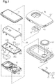
Fig. 1 is an exploded perspective view illustrating the schematic structure of a portable device; -
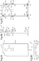
Fig. 2A is a front view illustrating a protection cover of the portable device; -
Fig. 2B is a side view of the protection cover illustrated inFig. 2A taken in the direction indicated by arrow A; -
Fig. 2C is a rear view of the protection cover illustrated inFig. 2A ; -
Fig. 2D is a side view of the protection cover illustrated inFig. 2A taken in the direction indicated by arrow B; -
Fig. 3A is a front view illustrating a first embodiment of a battery holder; -
Fig. 3B is a side view of the battery holder illustrated inFig. 3A taken in the direction indicated by arrow C; -
Fig. 3C is a rear view of the battery holder illustrated inFig. 3A ; -
Fig. 3D is a side view of the battery holder illustrated inFig. 3A taken in the direction indicated by arrow D; -
Fig. 3E is an enlarged perspective view illustrating an engaged portion of the battery holder illustrated inFig. 3A ; -
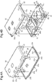
Figs. 4A and 4B are perspective views illustrating the procedures for unitizing a circuit board, the protection cover, and the battery holder; -
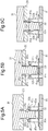
Figs. 5A to 5C are cross-sectional views illustrating movements of an engaging portion and the engaged portion when the protection cover is fastened to the battery holder; -
Fig. 6 is a perspective view illustrating a board unit of the first embodiment; -
Fig. 7A is a front view illustrating a second embodiment of a battery holder; -
Fig. 7B is a side view of the battery holder illustrated inFig. 7A taken in the direction indicated by arrow E; -
Fig. 7C is a rear view of the battery holder illustrated inFig. 7A ; -
Fig. 7D is a side view of the battery holder illustrated inFig. 7A taken in the direction indicated by arrow F; -
Fig. 7E is an enlarged perspective view illustrating an engaged portion of the battery holder illustrated inFig. 7A ; and -
Fig. 8 is a perspective view illustrating a board unit of the second embodiment. - A first embodiment of a portable device will now be described. The portable device of the first embodiment is, for example, an electronic key that is used for operating a vehicle in the electronic key system for the vehicle. When receiving a transmission signal from a vehicle controller installed in the vehicle, the electronic key performs wireless communication with the vehicle controller. The electronic key performs ID verification of the electronic key through short range communication with the vehicle controller and operates the vehicle, for example, locks or unlocks doors of the vehicle based on the result of ID verification.
- As illustrated in
Fig. 1 , the electronic key includes alower case 11 and anupper case 12, which is fastened to thelower case 11. Each of thelower case 11 and theupper case 12 is resin-molded and rectangular and includes two long sides and two short sides. When thelower case 11 is fastened to theupper case 12, the electronic key is box-shaped. - A
board unit 13 is accommodated in the electronic key, that is, between thelower case 11 and theupper case 12. A circuit element 13a, which enables a communication function or the like, is mounted on theboard unit 13. AlthoughFig. 1 illustrates only one circuit element 13a, a plurality of circuit elements may be mounted on theboard unit 13. Theboard unit 13 is fastened to aunit receptacle 11 a formed in thelower case 11. Theboard unit 13 includes abattery receptacle 13b, which accommodates a cylindrical (button-type)battery 14. - The
board unit 13 also includes a plurality (in present example, two) ofsquare switches 13c, which are arranged in the longitudinal direction of the electronic key. When eachswitch 13c is exposed from theboard unit 13 toward theupper case 12, theswitch 13c is accommodated in the electronic key. - The electronic key also accommodates a plurality of pushing
members 15, each of which has the form of a semicircular plate. In the present example, the electronic key includes two pushingmembers 15, the number of which is the same as the number of theswitches 13c. Theupper case 12 includes a plurality of semicircular throughholes 12a. In the present example, theupper case 12 includes two throughholes 12a, the number of which is the same as the number of the pushingmembers 15. The pushingmembers 15 are inserted from an inner side of theupper case 12 through the throughholes 12a. When the pushingmembers 15 are exposed out of the upper case 12 (i.e., electronic key), the pushingmembers 15 are accommodated in the electronic key. The two pushingmembers 15 are located at positions overlapping with the twoswitches 13c in the thickness-wise direction of the electronic key (vertical direction inFig. 1 ). When each pushingmember 15 is pushed from outside the electronic key, thecorresponding switch 13c is activated to enable the vehicle operation. - A
water guard 16 is located between eachswitch 13c and each pushingmember 15. Thewater guard 16 is molded from a resin such as silicone and rectangular and includes two long sides and two short sides. Thewater guard 16 is arranged to conceal the entire exposed portion of theboard unit 13 when theboard unit 13 is accommodated in theunit receptacle 11 a and held between thewater guard 16 and thelower case 11. Thewater guard 16 prevents entrance of foreign matter such as water or dust from the throughholes 12a in theupper case 12. - Additionally, a
mechanical key 17 is accommodated between thelower case 11 and theupper case 12. In the present example, thelower case 11 includes alower side groove 11 b, and theupper case 12 includes anupper side groove 12b. Thelower side groove 11 b and theupper side groove 12b define a key accommodation hole. Themechanical key 17 includes a key groove portion 17a having the form of an elongated plate. The key groove portion 17a is accommodated in the key accommodation hole. Themechanical key 17 includes ahandle 17b, which is exposed from the key accommodation hole. This allows the user to hold thehandle 17b and draw the mechanical key 17 out of the electronic key. The user may use themechanical key 17, which is drawn out of the electronic key, to manually operate the vehicle. - The structure of the
board unit 13 will now be described in detail. - As illustrated in
Fig. 1 , theboard unit 13 includes acircuit board 20, aprotection cover 30, and abattery holder 40, each of which is rectangular and includes two long sides and two short sides. Thecircuit board 20 includes end surfaces 20a that define the edges of therectangular circuit board 20. The end surfaces 20a include a plurality (in present example, six) ofcutaway portions 20b. Eachcutaway portion 20b is located in the periphery of thecircuit board 20 at an intermediate position in a straight portion (in present example, long side) or in a corner (position where long side intersects short side) of thecircuit board 20. Thecutaway portions 20b defineend portions 20e (indicated by shadings inFig. 1 ) that are separated from one another in the end surfaces 20a of thecircuit board 20. - The
circuit board 20 includes a surface opposed to thebattery holder 40 that defines acircuit area 20c and a surface opposed to theprotection cover 30 that defines aswitch area 20d. The circuit element 13a is mounted on thecircuit area 20c. Theswitches 13c are mounted on theswitch area 20d. Thecircuit area 20c and theswitch area 20d are located inward from theend portions 20e in a plan view. - When the
circuit board 20 is held between theprotection cover 30 and thebattery holder 40, theprotection cover 30 is fastened to thebattery holder 40. This unitizes thecircuit board 20, theprotection cover 30, and thebattery holder 40 as oneboard unit 13. In the present example, theend portions 20e of thecircuit board 20 are held between theprotection cover 30 and thebattery holder 40. In the first embodiment, thebattery holder 40 is one example of a first member, and theprotection cover 30 is one example of a second member. - The structure of the
protection cover 30 will now be described in detail. - As illustrated in
Figs. 2A to 2D , theprotection cover 30 includes aplate 31. Theplate 31 includes end surfaces that define the edges of theplate 31. In theboard unit 13, the end surfaces of theplate 31 are substantially flush with the corresponding end surfaces 20a of thecircuit board 20. Thus, theplate 31 and thecircuit board 20 have substantially the same size in a plan view (refer toFigs. 4A to 5C ). Theplate 31 includes a plurality (in present example, two) of throughholes 31 a. As described above, the throughholes 31 a are located at positions corresponding to theswitches 13c, which are mounted on thecircuit board 20. - The
protection cover 30 includes a plurality (in present example, six) of engagingportions 32. In theboard unit 13, the engagingportions 32 project from the periphery of theplate 31 toward the battery holder 40 (refer toFig. 4B ). The engagingportions 32 are spaced apart from one another and located at positions corresponding to thecutaway portions 20b of thecircuit board 20. Each engagingportion 32 may be fitted to the correspondingcutaway portion 20b. The length of each engagingportion 32 is set to be greater than the thickness of thecircuit board 20. Thebattery holder 40 includes aplate 41, which comes into contact with the distal end of each engagingportion 32 when theprotection cover 30 is coupled to the battery holder 40 (refer toFig. 5C ). - As illustrated in
Figs. 2B to 2D , each engagingportion 32 includes anextension 32a, which extends from the periphery of theplate 31 in the thickness-wise direction of theplate 31, and afirst hook 32b, which projects from theextension 32a in a direction extending along the periphery of theplate 31. In the present example, each engagingportion 32 further includes asecond hook 32c, which projects from theextension 32a toward an inner side of theplate 31. As illustrated inFigs. 4A and 4B , in theboard unit 13, theextensions 32a extend from theprotection cover 30 toward thebattery holder 40, and thefirst hooks 32b project in a direction extending along the corresponding end surfaces 20a of thecircuit board 20. - In the present example, the engaging
portions 32 include first engagingportions 32, each of which includes a plurality offirst hooks 32b, and second engagingportions 32, each of which includes a singlefirst hook 32b. As illustrated inFig. 2C , for example, three first engagingportions 32 and three second engagingportions 32 are arranged along the periphery of theplate 31. The firstengaging portions 32 are located in the periphery of theplate 31 at straight portions (in present example, two long sides). Each first engagingportion 32 includes twofirst hooks 32b, which project from opposite sides of theextension 32a in a direction extending along the corresponding edge of the plate 31 (i.e., correspondingend surface 20a of circuit board 20). - The second
engaging portions 32 are located in the periphery of theplate 31 at corners (in present example, three corners). Each second engagingportion 32 includes a singlefirst hook 32b, which projects from one side of theextension 32a in a direction extending along the corresponding edge of the plate 31 (i.e., correspondingend surface 20a of circuit board 20). - As illustrated in
Figs. 2B and 2C , each first engagingportion 32 includes a singlesecond hook 32c. As illustrated inFigs. 2B to 2D , each second engagingportion 32 also includes a singlesecond hook 32c. Thesecond hook 32c is located closer to the base of the engaging portion 32 (i.e., plate 31) than eachfirst hook 32b. Additionally, thesecond hook 32c is separated from the base of the engagingportion 32 by a distance corresponding to the thickness of thecircuit board 20. - The structure of the
battery holder 40 will now be described in detail. - As illustrated in
Figs. 3A to 3D , thebattery holder 40 includes theplate 41. Theplate 41 includes end surfaces that define the edges of theplate 41. In theboard unit 13, the end surfaces of theplate 41 are substantially flush with the corresponding end surfaces 20a of thecircuit board 20 and the corresponding end surfaces of the protection cover 30 (plate 31). Thus, theplate 41, thecircuit board 20, and the protection cover 30 (plate 31) have substantially the same size in a plan view (refer toFigs. 4A to 5C ). In theboard unit 13, thebattery holder 40 includeswalls 42, which extend from the periphery of theplate 41 toward theprotection cover 30. Theplate 41 includes a throughhole 43 that occupies one longitudinal half of theplate 41 and thebattery receptacle 13b that occupies the other longitudinal half of theplate 41. - The
battery holder 40 includes a plurality (in present example, six) of engagedportions 45, which are arranged along inner sides of thewalls 42. The engagedportions 45 are spaced apart from one another and located at positions corresponding to thecutaway portions 20b of thecircuit board 20, that is, the engagingportions 32 of theprotection cover 30. Engagement of the engagingportions 32 with the engagedportions 45 fastens theprotection cover 30 to thebattery holder 40. - As illustrated in
Figs. 3A, 3E ,4B ,6 , each engagedportion 45 includes apost 45a, which extends from theplate 41 in the thickness-wise direction of theplate 41, and acatch 45b, which extends from the distal end (upper end) of thepost 45a toward the correspondingwall 42. More specifically, each engagedportion 45 is L-shaped by thepost 45a and thehook catch 45b. The distal end of thehook catch 45b includes aninclined surface 45c, which is inclined from thehook catch 45b toward the base (lower end) of thepost 45a. Thehook catch 45b, which extends from thepost 45a toward thewall 42, is set to a length such that the distal end of thehook catch 45b will not come into contact with thewall 42. - The engaged
portions 45 include first engagedportions 45, each of which includes a plurality (in present example, two) ofposts 45a and a plurality (in present example, two) of hook catches 45b, and second engagedportions 45, each of which includes asingle post 45a and asingle hook catch 45b. As illustrated inFig. 3A , for example, three firstengaged portions 45 and three secondengaged portions 45 are located inward from thewalls 42 along the periphery of theplate 41. The firstengaged portions 45 are located in the periphery of theplate 41 at straight portions (in present example, two long sides). The twoposts 45a (two hook catches 45b) of each first engagedportion 45 are located adjacent to each other in the direction extending along the periphery of theplate 41. The distance between the two hook catches 45b of the first engagedportion 45 is set to be shorter than the distance between the distal ends of the twofirst hooks 32b of each first engaging portion 32 (refer toFig. 5A ). - The second
engaged portions 45 are located in the periphery of theplate 41 at corners (in present example, three corners). As described above, each second engagedportion 45 includes thesingle post 45a and thesingle hook catch 45b. - As illustrated in
Figs. 3A, 3B, 3D, 3E , thewalls 42 of thebattery holder 40 includeslits 44 at positions adjacent to the engagedportions 45. Each slit 44 extend through the correspondingwall 42 from the upper end to the lower end (plate 41) in a direction in which theextension 32a of the corresponding engagingportion 32 extends. When each engagingportion 32 engages the corresponding engagedportion 45, a portion of theextension 32a (portion of outer wall) is fitted to theslit 44. In the present example, theslit 44 defines a portion of the engagedportion 45. - As illustrated in
Figs. 3A to 3E ,thick portions 46 are located outward from thewalls 42 in correspondence with the slits 44 (engaged portions 45). Eachthick portion 46 is one example of a support portion and formed by a portion of thecorresponding wall 42. Thethick portion 46 is formed, for example, by increasing the thickness of thewall 42. When the board unit 13 (battery holder 40) is accommodated in thelower case 11, thethick portions 46 are in contact with inner walls of theunit receptacle 11 a. Eachthick portion 46 functions as a position stabilizer, which stably fastens theboard unit 13 to theunit receptacle 11a. In the present example, thethick portions 46 are also located outward from thewalls 42 at positions that are free from the slits 44 (engaged portions 45). - As illustrated in
Figs. 3A, 3E ,6 , each of thethick portions 46 located at the firstengaged portions 45 conceals opposite edges defining theslit 44 and opposite ends of the outer wall of the first engaging portion 32 (extension 32a) in a direction extending along thecorresponding end surface 20a of thecircuit board 20. In other words, thethick portions 46 located at the firstengaged portions 45 each include agap 47 that exposes a central portion of the outer wall of the first engaging portion 32 (extension 32a). As illustrated inFigs. 3A and6 , each of thethick portions 46 located at the secondengaged portions 45 conceals one of edges defining theslit 44 and a portion of the outer wall of the second engaging portion 32 (extension 32a). Thefirst hook 32b of the second engagingportion 32 and the correspondingthick portion 46 are located at opposite sides of theextension 32a of the second engagingportion 32. - The procedures for unitizing the
circuit board 20, theprotection cover 30, and thebattery holder 40 as theboard unit 13 will now be described. - As illustrated in
Fig. 4A , thecircuit board 20 is coupled to theprotection cover 30. When thecircuit board 20 is coupled to theprotection cover 30, theextensions 32a of the engagingportions 32 are opposed to the end surfaces 20a of thecircuit board 20. Also, each engagingportion 32 is inserted into the correspondingcutaway portion 20b. At this time, when theprotection cover 30 is located proximate to thecircuit board 20, thesecond hook 32c of each engagingportion 32 comes into contact with one surface (switcharea 20d) of thecircuit board 20 at the correspondingcutaway portion 20b. Then, when thecircuit board 20 is pressed to theprotection cover 30, the engagingportions 32 elastically deform, and thesecond hooks 32c of the engagingportions 32 are moved to the other surface (circuit area 20c) of thecircuit board 20. Consequently, when thecircuit board 20 is coupled to theprotection cover 30, thesecond hooks 32c of the engagingportions 32 are hooked on the edges of thecircuit board 20 to support thecircuit board 20. In this state, theplate 31 of theprotection cover 30 is in contact with theend portions 20e of thecircuit board 20 between adjacent ones of the engagingportions 32. Thesecond hook 32c of each engagingportion 32 functions as a temporary fastening hook, which temporarily fastens thecircuit board 20 to theprotection cover 30. - As illustrated in
Fig. 4B , theprotection cover 30, to which thecircuit board 20 is temporarily fastened, is coupled to thebattery holder 40. At this time, the engagingportions 32 of theprotection cover 30 are inserted into the engagedportions 45 of thebattery holder 40 and theslits 44 of thewalls 42. Then, when theprotection cover 30 is pressed to thebattery holder 40, thefirst hooks 32b of the engagingportions 32 are hooked on the hook catches 45b of the engagedportions 45. This fastens theprotection cover 30 to thebattery holder 40. In this state, thebattery holder 40 is in contact with theend portions 20e of thecircuit board 20 between adjacent ones of the engagedportions 45. As described above, engagement of thefirst hooks 32b of the engagingportions 32 with the engagedportions 45 fastens theprotection cover 30 to thebattery holder 40. Thus, eachfirst hook 32b functions as a main fastening hook, which ultimately fastens thecircuit board 20 to theprotection cover 30 and thebattery holder 40. - The operation of the engagement of the first engaging
portions 32 of theprotection cover 30 with the firstengaged portions 45 of thebattery holder 40 will now be described with reference toFigs. 5A to 5C . As illustrated inFig. 5A , the distal end of theextension 32a of the first engagingportion 32 is inserted into the gap between the two hook catches 45b of the first engagedportion 45. The first hooks 32b come into contact with theinclined surfaces 45c of the corresponding hook catches 45b. At this time, the outer wall of theextension 32a is partially fitted into theslit 44 of the wall 42 (refer toFig. 6 ). As illustrated inFig. 5B , when the first engagingportion 32 is further inserted into the first engagedportion 45, thefirst hooks 32b press theinclined surfaces 45c of the hook catches 45b to move the two hook catches 45b away from each other. Accordingly, the twoposts 45a elastically deform to separate away from each other. As illustrated inFig. 5C , when thefirst hooks 32b pass by the hook catches 45b (inclined surfaces 45c), theposts 45a recover from the elastic deformation, and thefirst hooks 32b are hooked on the hook catches 45b. In this state, the distal end of theextension 32a is in contact with theplate 41 of thebattery holder 40. Although not described, the secondengaging portions 32 engage the secondengaged portions 45 in the same manner as the engagement of the first engagingportions 32 with the firstengaged portions 45. Additionally, the outer wall of theextension 32a of each second engagingportion 32 is partially inserted into thecorresponding slit 44 in the walls 42 (refer toFig. 6 ). In this manner, theprotection cover 30 is fastened to thebattery holder 40. - Consequently, as illustrated in
Fig. 6 , thecircuit board 20 is ultimately fastened to theprotection cover 30 and thebattery holder 40. Thecircuit board 20, theprotection cover 30, and thebattery holder 40 are unitized as oneboard unit 13. - Referring to
Fig. 6 (left enlarged perspective view and center enlarged cross-sectional view), theextension 32a of each engagingportion 32 is opposed to thecorresponding end surface 20a of thecircuit board 20. Also, referring toFig. 6 (left enlarged perspective view), the one or twofirst hooks 32b of each engagingportion 32 project in a direction extending along thecorresponding end surface 20a of thecircuit board 20. As illustrated inFig. 6 (left enlarged perspective view), thethick portion 46 located at the first engagingportion 32 conceals opposite edges defining theslit 44 and opposite ends of the outer wall of theextension 32a in the direction extending along thecorresponding end surface 20a of thecircuit board 20, and the remaining portion (central portion) of the outer wall of theextension 32a is exposed through theslit 44 and thegap 47 formed in thethick portion 46. As illustrated inFig. 6 (right enlarged perspective view), thethick portion 46 located at the second engagingportion 32 conceals one edge defining theslit 44 and a portion of the outer wall of theextension 32a, and the remaining portion of the outer wall of theextension 32a is exposed through theslit 44. That is, the outer wall of theextension 32a of the second engagingportion 32 is partially covered by thethick portion 46 located at the side of the second engagingportion 32 opposite to the side where thefirst hook 32b is located. Eachfirst hook 32b, more specifically, the engagement state of eachfirst hook 32b with thecorresponding hook catch 45b, is concealed from the exterior by thewalls 42 or thethick portions 46. Referring toFig. 6 (center enlarged cross-sectional view), thesecond hooks 32c of the engagingportions 32 are hooked on the edges of thecircuit board 20 to support thecircuit board 20. - In the
board unit 13, eachswitch 13c is exposed through the corresponding throughhole 31 a in theprotection cover 30. The circuit element 13a is exposed through the through hole 43 (refer toFig. 3A ) in thebattery holder 40. - The operation of the first embodiment of the portable device will now be described.
- When the
first hooks 32b of the engagingportions 32 of theprotection cover 30 engage the engagedportions 45 of thebattery holder 40, theprotection cover 30 is fastened to thebattery holder 40. This fastens thecircuit board 20 to theprotection cover 30 and thebattery holder 40. The one or twofirst hooks 32b of each engagingportion 32 do not project toward thecircuit board 20 but project in a direction extending along thecorresponding end surface 20a of thecircuit board 20. When theprotection cover 30 is fastened to thebattery holder 40, thefirst hooks 32b are concealed by thewalls 42 or thethick portions 46 and are not exposed from theprotection cover 30 and thebattery holder 40 to the exterior. - This structure prevents the
first hooks 32b from occupying thecircuit area 20c of thecircuit board 20 as compared to a structure in which engagement hooks that engage with the battery holder project toward the battery holder (e.g., structure in Japanese Laid-Open Patent Publication No.2013-19224 - The
protection cover 30 includes the first engagingportions 32, each of which includes a plurality offirst hooks 32b, and the secondengaging portions 32, each of which includes a singlefirst hook 32b. More specifically, the number of thefirst hooks 32b is optimized in accordance with the position of each engagingportion 32. This optimizes the shapes of theprotection cover 30 and thebattery holder 40. - If, for example, a first engaging
portion 32 that includes a plurality offirst hooks 32b is located in a corner of theprotection cover 30, the structure of the engagedportion 45 located at the corresponding corner of thebattery holder 40 would be complicated. This complicates the structure of thebattery holder 40 in addition to the structure of theprotection cover 30. - In this regard, in the present example, as illustrated in
Fig. 2C , the first engagingportions 32 are located in the periphery of theprotection cover 30 at the straight portions (in present example, long sides). The secondengaging portions 32 are located in the periphery of theprotection cover 30 at the corners. Thus, the number offirst hooks 32b is adjusted in accordance with the position of each engagingportion 32 to arrange different engaging portions 32 (first engagingportions 32, second engaging portions 32). - When each second engaging
portion 32 is located in a corner of theprotection cover 30, the coupling of theprotection cover 30 to thebattery holder 40 moves the second engagingportion 32 in a direction opposite to the direction in which thefirst hook 32b projects. More specifically, the second engagingportion 32 is separated from the second engagedportion 45 and may be disengaged from the second engagedportion 45. - In this regard, in the present example, the outer wall of the second engaging portion 32 (
extension 32a) located in the corner of theprotection cover 30 is partially covered by thethick portion 46 located at the side of the second engagingportion 32 opposite to the side where thefirst hook 32b is located. Thus, thethick portion 46 prevents the second engagingportion 32 from moving in the direction opposite to the direction in which thefirst hook 32b projects. This prevents disengagement of the second engagingportion 32 from the second engagedportion 45. - In the present example, when the
circuit board 20 is held and fastened between theprotection cover 30 and thebattery holder 40, thesecond hooks 32c of theprotection cover 30 temporarily fasten thecircuit board 20 to theprotection cover 30. Thus, theprotection cover 30 may be coupled to thebattery holder 40 with thecircuit board 20 temporarily fastened to theprotection cover 30. This facilitates the coupling of thecircuit board 20 to theprotection cover 30 and thebattery holder 40. - The second hooks 32c of the engaging
portions 32 project toward the corresponding end surfaces 20a of thecircuit board 20. This further reduces the size of each engagingportion 32. - If, for example, the first and
second hooks portion 32 are all configured to project toward thecorresponding end surface 20a of thecircuit board 20, the first andsecond hooks portion 32. This increases the size of each engagingportion 32. In this regard, in the present example, while thefirst hooks 32b project in the direction extending along theend surface 20a of thecircuit board 20, thesecond hooks 32c project toward theend surface 20a of thecircuit board 20. This restricts thefirst hooks 32b from occupying thecircuit area 20c of thecircuit board 20 and also limits increases in the size of the engagingportion 32. However, obtainment of the engagingportion 32 including the above first andsecond hooks 2013-19224 - Referring to
Fig. 6 (left enlarged perspective view and right enlarged perspective view), when each engagingportion 32 engages the corresponding engagedportion 45, the outer wall of theextension 32a of the engagingportion 32 is partially fitted into thecorresponding slit 44. - This fastens the
battery holder 40 to theprotection cover 30 in a firmer manner at positions where theslits 44 are located. Additionally, theslits 44 allow the engagingportions 32 to be located closer to thewalls 42. This enlarges thecircuit area 20c without increasing the sizes of theprotection cover 30 and thebattery holder 40. - The first embodiment has the advantages described below.
- (1) The first hooks 32b of the engaging
portions 32 project in the direction extending along the corresponding end surfaces 20a of thecircuit board 20. This structure prevents thefirst hooks 32b from occupying thecircuit area 20c of thecircuit board 20 as compared to a structure in which engagement hooks that engage with the battery holder project toward the battery holder, or the circuit board, (e.g., structure in Japanese Laid-Open Patent Publication No.2013-19224 portions 32 and thewalls 42 are located at a further inner side toward thecircuit board 20, thecircuit area 20c is ensured in thecircuit board 20. This reduces the sizes of theprotection cover 30 and thebattery holder 40 without reducing the space of thecircuit area 20c. - (2) The
protection cover 30 includes the first engaging portions, each of which includes a plurality offirst hooks 32b, and the second engaging portions, each of which includes a singlefirst hook 32b. In this structure, the number of thefirst hooks 32b is optimized in accordance with the position of each engagingportion 32. This optimizes the shapes of theprotection cover 30 and thebattery holder 40. - (3) The first
engaging portions 32 are located in the periphery of theprotection cover 30 at the straight portions. The secondengaging portions 32 are located in the periphery of theprotection cover 30 at the corners. Different engaging portions 32 (first engagingportions 32, second engaging portions 32) are arranged just by adjusting the number offirst hooks 32b in accordance with the position of each engagingportion 32. This structure limits complication of the structures of theprotection cover 30 and thebattery holder 40. - (4) The outer wall of each second engaging portion 32 (
extension 32a) is partially covered by thethick portion 46 located at the side of the second engagingportion 32 opposite to the side where thefirst hook 32b is located. Thus, thethick portion 46 prevents the second engagingportion 32 from moving in the direction opposite to the direction in which thefirst hook 32b projects. This prevents disengagement of the second engagingportion 32 from the second engagedportion 45 at the corner of theprotection cover 30. - (5) Each engaging
portion 32 includes the one or twofirst hooks 32b, which project in the direction extending along thecorresponding end surface 20a of thecircuit board 20, and thesecond hook 32c, which projects toward thecircuit board 20. Thus, the engagingportion 32 having the temporary fastening function (second hook 32c) and the main fastening function (first hook 32b) may be formed in a smaller size. - (6) When each engaging
portion 32 engages the corresponding engagedportion 45, the outer wall of theextension 32a of the engagingportion 32 is partially fitted into thecorresponding slit 44. This fastens thebattery holder 40 to theprotection cover 30 in a firmer manner. Additionally, theslits 44 allow the engagingportions 32 to be located closer to thewalls 42. This enlarges thecircuit area 20c without increasing the sizes of theprotection cover 30 and thebattery holder 40. In other words, theslits 44 allow thewalls 42 to be located closer to thecircuit board 20. This reduces the sizes of theprotection cover 30 and thebattery holder 40 without reducing the space of thecircuit area 20c. - A second embodiment of a portable device will now be described. The same reference characters are given to those components that are the same as the corresponding components of the first embodiment. Such components will not be described in detail.
- As illustrated in
Figs. 7A to 7E , in the second embodiment, thewalls 42 of thebattery holder 40 are free from thethick portions 46 of the first embodiment. More specifically, thewalls 42 include a flat surface having no irregularities. Thus, as illustrated inFig. 8 , in theboard unit 13, thewalls 42 of the battery holder 40 (end surfaces of plate 41) are flush with the corresponding end surfaces 20a of thecircuit board 20 and the corresponding end surfaces of the protection cover 30 (end surfaces of plate 31). Thebattery holder 40, thecircuit board 20, and theprotection cover 30 have the same size in a plan view. - Additionally, as illustrated in
Fig. 8 , when thecircuit board 20, theprotection cover 30, and thebattery holder 40 are unitized as theboard unit 13, the outer wall of theextension 32a of each of the first engaging portions and the second engaging portions is entirely exposed to the exterior through thecorresponding slit 44. The outer wall of eachextension 32a is flush with the correspondingwall 42 of the battery holder 40 (corresponding end surface of plate 41), thecorresponding end surface 20a of thecircuit board 20, and the corresponding end surface of the protection cover 30 (corresponding end surface of plate 31). The first hooks 32b of the engagingportions 32, that is, the engagement states of thefirst hooks 32b with the hook catches 45b, are concealed by thewalls 42. - The second embodiment has the advantages described below in addition to advantages (1) to (3), (5), (6) of the first embodiment.
- (7) The second embodiment is configured not to include the
thick portions 46. Thus, the thickness of thewalls 42, that is, the size of thebattery holder 40, is reduced as compared to the first embodiment, which is configured to include thethick portions 46. - This reduces the size of the
battery holder 40 while ensuring the space of thecircuit area 20c. In other words, thecircuit area 20c is enlarged without increasing the size of thebattery holder 40. - (8) The outer wall of the
extension 32a of each of the first engagingportions 32 and the secondengaging portions 32 is flush with the correspondingwall 42 of the battery holder 40 (corresponding end surface of plate 41), thecorresponding end surface 20a of thecircuit board 20, and the corresponding end surface of the protection cover 30 (corresponding end surface of plate 31). Thus, when theprotection cover 30 is fastened to thebattery holder 40, there is no step between each engagingportion 32 and the corresponding engagedportion 45. This prevents unauthorized removal of theprotection cover 30 from thebattery holder 40 by inserting a tool such as a screwdriver into a gap formed between theprotection cover 30 and thebattery holder 40. Thus, unauthorized obtainment and tampering of thecircuit board 20 are prevented. This increases the reliability of the electronic key. - It should be apparent to those skilled in the art that the foregoing embodiments may be employed in many other specific forms without departing from this disclosure. Particularly, it should be understood that the foregoing embodiments may be employed in the following forms.
- The fitting portions of the
walls 42 may be holes or grooves instead of theslits 44. In this case, advantage (6) is obtained as long as when the engagingportions 32 engage the engagedportions 45, theextensions 32a are partially fitted to the fitting portions (slits 44, holes, grooves, etc.) in thewalls 42. - In the first embodiment, the
thick portions 46 may be entirely or partially used to form theslits 44. - All of the engaging
portions 32 do not necessarily have to include thesecond hooks 32c. Theprotection cover 30 may include, for example, engagingportions 32 that include thesecond hooks 32c and engagingportions 32 that do not include thesecond hooks 32c. In each of the above embodiments, each engagingportion 32 includes the singlesecond hook 32c. However, any one of the engagingportions 32 may include two or moresecond hooks 32c. For example, while a first engagingportion 32 located in a straight portion (long side or short side) of theprotection cover 30 includes two or moresecond hooks 32c, a second engagingportion 32 located in a corner of theprotection cover 30 may include a singlesecond hook 32c. - To temporarily fasten the
circuit board 20 to theprotection cover 30, when thecircuit board 20 has a structure corresponding to thesecond hooks 32c of the engagingportions 32, theprotection cover 30 may have a structure corresponding to thecutaway portions 20b of thecircuit board 20. Alternatively, thecircuit board 20 may be temporarily fastened to theprotection cover 30 and thebattery holder 40 by fastening members such as screws and bolts. Thecircuit board 20 may be temporarily fastened to thebattery holder 40. - The engaging
portions 32 do not have to include thesecond hooks 32c. More specifically, the temporary fastening function may be omitted. In this case, theprotection cover 30 is fastened to thebattery holder 40 with thecircuit board 20 held between theprotection cover 30 and thebattery holder 40. - Each engaging
portion 32 may include a plurality offirst hooks 32b. For example, in each of the above embodiments, instead of the secondengaging portions 32, the first engagingportions 32 may be located in corners of theprotection cover 30. When theprotection cover 30 is coupled to thebattery holder 40, this structure restricts separation and disengagement of the first engagingportions 32 located in the corners of theprotection cover 30 from the firstengaged portions 45. Hence, for example, in the first embodiment, thethick portions 46 may be omitted from positions corresponding to the corners of theprotection cover 30. Alternatively, each engagingportion 32 may include a singlefirst hook 32b. In the first embodiment, the outer wall of each engaging portion 32 (extension 32a) located at a long side of theprotection cover 30 is partially covered by thethick portion 46. This limits separation of the engagingportion 32 even when each engagingportion 32 includes the singlefirst hook 32b. - The
protection cover 30 may include engagingportions 32 that include thefirst hooks 32b and engagingportions 32 that do not includefirst hooks 32b. Further, each engagingportion 32 may include three or morefirst hooks 32b. For example, when an engagingportion 32 that includes three or morefirst hooks 32b is located in a straight portion (long side or short side) of theprotection cover 30, an engagingportion 32 that includes one or twofirst hooks 32b may be located in a corner of theprotection cover 30. - In the first embodiment, the support portion that covers a portion of the outer wall of each second engaging portion 32 (
extension 32a) may be a portion of thewall 42 instead of thethick portion 46. That is, the support portion may have the same thickness as thewall 42. - In the first embodiment, the entire outer wall of each second engaging portion 32 (
extension 32a) may be concealed by thethick portion 46. This limits separation of the second engagingportion 32 from the second engagedportion 45 in a further favorable manner. - The
circuit board 20, theprotection cover 30, and thebattery holder 40 may be circular in a plan view. In this case, each engagingportion 32 may include a plurality offirst hooks 32b. - The
circuit board 20, theprotection cover 30, and thebattery holder 40 may have different shapes in a plan view. For example, when thecircuit board 20 is circular in a plan view, theprotection cover 30 and thebattery holder 40 may be rectangular in a plan view. Alternatively, when thecircuit board 20 and theprotection cover 30 are rectangular in a plan view, thebattery holder 40 may be circular in a plan view. - The
protection cover 30 may include only one engagingportion 32. In this case, only a hinge needs to be located at a position opposite to the position of the engagingportion 32 so that, for example, theprotection cover 30 is pivotally supported by thebattery holder 40 with the hinge. - The number of the
switches 13c and the number of the pushingmembers 15 may be one or three or more. In this case, the number of the throughholes 12a in theupper case 12 and the number of the throughholes 31 a in theprotection cover 30 only need to be changed accordingly. - The electronic key (portable device) may be capable of opening and closing a sliding door of a vehicle in addition to the locking and unlocking of the doors of the vehicle. The application of the electronic key (portable device) is not limited to an electronic key for a vehicle. The electronic key (portable device) may be applied to an electronic key used for a house and capable of locking and unlocking a door of the house.
- All examples and conditional language recited herein are intended for pedagogical purposes to aid the reader in understanding the principles of the invention and the concepts contributed by the inventor to furthering the art, and are to be construed as being without limitation to such specifically recited examples and conditions, nor does the organization of such examples in the specification relate to an illustration of the superiority and inferiority of the invention. Although embodiments have been described in detail, it should be understood that various changes, substitutions, and alterations could be made hereto without departing from the scope of this disclosure.
- A portable device includes a circuit board (20), a first member (40), and a second member (30). The circuit board (20) is held and fastened between the first member (40) and the second member (30). The first member (40) includes a wall (42) that extends toward the second member (30) from the first member (40). The second member (30) includes an engaging portion (32). The engaging portion (32) includes an extension (32a), which extends toward the first member (40) from the second member (30), and a hook (32b), which projects from the extension (32a) in a direction extending along an end surface (20a) of the circuit board (20). The portable device further includes an engaged portion (45) located along an inner side of the wall (42). Engagement of the engaged portion (45) with the hook (32b) of the engaging portion (32) fastens the first member (40) to the second member (30).
Claims (6)
- A portable device comprising:a circuit board (20) on which a circuit element (13a) is mounted;a first member (40); anda second member (30), wherein the circuit board (20) is held and fastened between the first member (40) and the second member (30),the portable device characterized in that:the first member (40) includes a wall (42) that extends toward the second member (30) from the first member (40);the second member (30) includes an engaging portion (32), wherein the engaging portion (32) includes an extension (32a) that extends toward the first member (40) from the second member (30) and a hook (32b) that projects from the extension (32a);the circuit board (20) includes an end surface (20a) that defines an edge of the circuit board (20);the extension (32a) is opposed to the end surface (20a) of the circuit board (20);the hook (32b) projects from the extension (32a) in a direction that extends along the end surface (20a) of the circuit board (20); andthe portable device (40) further comprises an engaged portion (45) located along an inner side of the wall (42), wherein the engaged portion (45) is configured to engage the engaging portion (32) to fasten the first member (40) to the second member (30).
- The portable device according to claim 1, wherein
the engaging portion (32) is one of a plurality of engaging portions (32) included in the second member (30), and
the plurality of engaging portions (32) includea first engaging portion (32) that includes the extension (32a) and a plurality of hooks (32b) that project from opposite sides of the extension (32a) in the direction that extends along the end surface (20a) of the circuit board (20), anda second engaging portion (32) that includes the extension (32a) and a single hook (32b) that projects from one side of the extension (32a) in the direction that extends along the end surface (20a) of the circuit board (20). - The portable device according to claim 2, wherein
the second member (30) includes a rectangular periphery,
the first engaging portion (32) is located in the periphery of the second member (30) at a straight portion, and
the second engaging portion (32) is located in the periphery of the second member (30) at a corner. - The portable device according to claim 3, wherein
the wall (42) of the first member (40) includes a support portion (46) that covers at least a portion of an outer wall of the second engaging portion (32) located at the corner of the second member (30), and
the hook (32b) of the second engaging portion (32) and the support portion (46) are located at opposite sides of the extension (32a) of the second engaging portion (32). - The portable device according to any one of claims 1 to 4, wherein
the engaging portion (32) further includes a temporary fastening hook (32c) projecting toward the end surface (20a) of the circuit board (20) and configured to temporarily fasten the circuit board (20) to the second member (30). - The portable device according to any one of claims 1 to 5, wherein
the wall (42) includes a slit (44) that extends in a direction in which the extension (32a) extends, and
a portion of the extension (32a) is fitted into the slit (44) in a state in which the engaging portion (32) engages the engaged portion (45).
Applications Claiming Priority (1)
| Application Number | Priority Date | Filing Date | Title |
|---|---|---|---|
| JP2015215157A JP6082798B1 (en) | 2015-10-30 | 2015-10-30 | Portable machine |
Publications (2)
| Publication Number | Publication Date |
|---|---|
| EP3163756A1 true EP3163756A1 (en) | 2017-05-03 |
| EP3163756B1 EP3163756B1 (en) | 2018-09-12 |
Family
ID=57288141
Family Applications (1)
| Application Number | Title | Priority Date | Filing Date |
|---|---|---|---|
| EP16195477.1A Active EP3163756B1 (en) | 2015-10-30 | 2016-10-25 | Portable device |
Country Status (3)
| Country | Link |
|---|---|
| US (1) | US9750146B2 (en) |
| EP (1) | EP3163756B1 (en) |
| JP (1) | JP6082798B1 (en) |
Families Citing this family (2)
| Publication number | Priority date | Publication date | Assignee | Title |
|---|---|---|---|---|
| US10346735B1 (en) * | 2018-09-29 | 2019-07-09 | Wen-Yi Lee | Assembling buckle structure for memory circuit board |
| CN112533401B (en) * | 2019-09-17 | 2023-04-28 | 台达电子工业股份有限公司 | Anti-dismantling device |
Citations (4)
| Publication number | Priority date | Publication date | Assignee | Title |
|---|---|---|---|---|
| KR20080075783A (en) * | 2007-02-13 | 2008-08-19 | 가부시키가이샤 덴소 | Handheld electronic key system |
| JP2013019224A (en) | 2011-07-13 | 2013-01-31 | Denso Corp | Portable machine |
| WO2015104747A1 (en) * | 2014-01-07 | 2015-07-16 | 株式会社デンソー | Vehicle electronic key system portable device |
| EP2924664A1 (en) * | 2014-03-25 | 2015-09-30 | Novoferm tormatic GmbH | Handheld transmitter |
Family Cites Families (8)
| Publication number | Priority date | Publication date | Assignee | Title |
|---|---|---|---|---|
| JPS5945903U (en) * | 1982-09-17 | 1984-03-27 | 松下電器産業株式会社 | Variable resistor with switch |
| US5946395A (en) * | 1997-08-29 | 1999-08-31 | Motorola, Inc. | Housing assembly for an electronic device |
| US5955700A (en) * | 1997-12-30 | 1999-09-21 | Motorola, Inc. | Housing unit including a latching mechanism with a cam |
| US6111760A (en) * | 1998-12-30 | 2000-08-29 | Ericsson, Inc. | Simple enclosure for electronic components |
| JP4287559B2 (en) * | 1999-11-16 | 2009-07-01 | 日本発條株式会社 | Socket for electronic parts |
| JP3901545B2 (en) * | 2002-03-04 | 2007-04-04 | ティーオーエー株式会社 | Housing with fitting structure |
| JP2003309384A (en) * | 2002-04-17 | 2003-10-31 | Denso Corp | Current switching circuit device and electric power steering circuit device |
| JP5956948B2 (en) * | 2013-03-21 | 2016-07-27 | 日立オートモティブシステムズ株式会社 | Electronic control unit |
-
2015
- 2015-10-30 JP JP2015215157A patent/JP6082798B1/en active Active
-
2016
- 2016-10-18 US US15/296,315 patent/US9750146B2/en active Active
- 2016-10-25 EP EP16195477.1A patent/EP3163756B1/en active Active
Patent Citations (4)
| Publication number | Priority date | Publication date | Assignee | Title |
|---|---|---|---|---|
| KR20080075783A (en) * | 2007-02-13 | 2008-08-19 | 가부시키가이샤 덴소 | Handheld electronic key system |
| JP2013019224A (en) | 2011-07-13 | 2013-01-31 | Denso Corp | Portable machine |
| WO2015104747A1 (en) * | 2014-01-07 | 2015-07-16 | 株式会社デンソー | Vehicle electronic key system portable device |
| EP2924664A1 (en) * | 2014-03-25 | 2015-09-30 | Novoferm tormatic GmbH | Handheld transmitter |
Also Published As
| Publication number | Publication date |
|---|---|
| JP2017085522A (en) | 2017-05-18 |
| US9750146B2 (en) | 2017-08-29 |
| JP6082798B1 (en) | 2017-02-15 |
| EP3163756B1 (en) | 2018-09-12 |
| US20170127541A1 (en) | 2017-05-04 |
Similar Documents
| Publication | Publication Date | Title |
|---|---|---|
| TWI690795B (en) | Fixing mechanism and related electronic apparatus | |
| CN109891040B (en) | Locking system for a door | |
| EP0138022B1 (en) | Housing for electronic apparatus or the like | |
| EP3163756B1 (en) | Portable device | |
| US8218314B2 (en) | Cover mechanism and electronic device using same | |
| JP5929025B2 (en) | Portable machine | |
| CA2709447C (en) | Assembly for housing a memory card in an electronic device | |
| US20100311259A1 (en) | Cover structure for portable electronic devices | |
| JP5004349B2 (en) | Portable machine | |
| US8050025B2 (en) | Cover mechanism and electronic device using same | |
| US9140040B2 (en) | Latch assembly with automatic returning bolt | |
| CN106919230A (en) | Fixtures | |
| CN104251077B (en) | Component with belt fastener and intelligent key | |
| KR20180075926A (en) | Junction box | |
| US20130113347A1 (en) | Locking mechanism with easy assembly and electronic device therewith | |
| US9471100B2 (en) | Electronic device | |
| EP3037610A1 (en) | Locking device | |
| US8212166B2 (en) | Switch assembly | |
| US6464518B1 (en) | Socket with a cover member | |
| US11940854B2 (en) | Replacement device and electronic device | |
| KR100656399B1 (en) | Hook coupling structure and case using the same | |
| CN111587017B (en) | Shell assembly and electronic equipment | |
| CN203102118U (en) | Case and cover body thereof | |
| CN213510048U (en) | Cabinet lock | |
| CN101807764B (en) | Electric connector |
Legal Events
| Date | Code | Title | Description |
|---|---|---|---|
| PUAI | Public reference made under article 153(3) epc to a published international application that has entered the european phase |
Free format text: ORIGINAL CODE: 0009012 |
|
| 17P | Request for examination filed |
Effective date: 20161025 |
|
| AK | Designated contracting states |
Kind code of ref document: A1 Designated state(s): AL AT BE BG CH CY CZ DE DK EE ES FI FR GB GR HR HU IE IS IT LI LT LU LV MC MK MT NL NO PL PT RO RS SE SI SK SM TR |
|
| AX | Request for extension of the european patent |
Extension state: BA ME |
|
| GRAP | Despatch of communication of intention to grant a patent |
Free format text: ORIGINAL CODE: EPIDOSNIGR1 |
|
| RIC1 | Information provided on ipc code assigned before grant |
Ipc: H04B 1/034 20060101AFI20180221BHEP |
|
| INTG | Intention to grant announced |
Effective date: 20180319 |
|
| GRAS | Grant fee paid |
Free format text: ORIGINAL CODE: EPIDOSNIGR3 |
|
| GRAA | (expected) grant |
Free format text: ORIGINAL CODE: 0009210 |
|
| AK | Designated contracting states |
Kind code of ref document: B1 Designated state(s): AL AT BE BG CH CY CZ DE DK EE ES FI FR GB GR HR HU IE IS IT LI LT LU LV MC MK MT NL NO PL PT RO RS SE SI SK SM TR |
|
| REG | Reference to a national code |
Ref country code: GB Ref legal event code: FG4D |
|
| REG | Reference to a national code |
Ref country code: CH Ref legal event code: EP |
|
| REG | Reference to a national code |
Ref country code: IE Ref legal event code: FG4D |
|
| REG | Reference to a national code |
Ref country code: DE Ref legal event code: R096 Ref document number: 602016005531 Country of ref document: DE |
|
| REG | Reference to a national code |
Ref country code: AT Ref legal event code: REF Ref document number: 1041804 Country of ref document: AT Kind code of ref document: T Effective date: 20181015 |
|
| REG | Reference to a national code |
Ref country code: FR Ref legal event code: PLFP Year of fee payment: 3 |
|
| REG | Reference to a national code |
Ref country code: NL Ref legal event code: MP Effective date: 20180912 |
|
| REG | Reference to a national code |
Ref country code: LT Ref legal event code: MG4D |
|
| PG25 | Lapsed in a contracting state [announced via postgrant information from national office to epo] |
Ref country code: NO Free format text: LAPSE BECAUSE OF FAILURE TO SUBMIT A TRANSLATION OF THE DESCRIPTION OR TO PAY THE FEE WITHIN THE PRESCRIBED TIME-LIMIT Effective date: 20181212 Ref country code: GR Free format text: LAPSE BECAUSE OF FAILURE TO SUBMIT A TRANSLATION OF THE DESCRIPTION OR TO PAY THE FEE WITHIN THE PRESCRIBED TIME-LIMIT Effective date: 20181213 Ref country code: BG Free format text: LAPSE BECAUSE OF FAILURE TO SUBMIT A TRANSLATION OF THE DESCRIPTION OR TO PAY THE FEE WITHIN THE PRESCRIBED TIME-LIMIT Effective date: 20181212 Ref country code: FI Free format text: LAPSE BECAUSE OF FAILURE TO SUBMIT A TRANSLATION OF THE DESCRIPTION OR TO PAY THE FEE WITHIN THE PRESCRIBED TIME-LIMIT Effective date: 20180912 Ref country code: LT Free format text: LAPSE BECAUSE OF FAILURE TO SUBMIT A TRANSLATION OF THE DESCRIPTION OR TO PAY THE FEE WITHIN THE PRESCRIBED TIME-LIMIT Effective date: 20180912 Ref country code: RS Free format text: LAPSE BECAUSE OF FAILURE TO SUBMIT A TRANSLATION OF THE DESCRIPTION OR TO PAY THE FEE WITHIN THE PRESCRIBED TIME-LIMIT Effective date: 20180912 Ref country code: SE Free format text: LAPSE BECAUSE OF FAILURE TO SUBMIT A TRANSLATION OF THE DESCRIPTION OR TO PAY THE FEE WITHIN THE PRESCRIBED TIME-LIMIT Effective date: 20180912 |
|
| PG25 | Lapsed in a contracting state [announced via postgrant information from national office to epo] |
Ref country code: AL Free format text: LAPSE BECAUSE OF FAILURE TO SUBMIT A TRANSLATION OF THE DESCRIPTION OR TO PAY THE FEE WITHIN THE PRESCRIBED TIME-LIMIT Effective date: 20180912 Ref country code: LV Free format text: LAPSE BECAUSE OF FAILURE TO SUBMIT A TRANSLATION OF THE DESCRIPTION OR TO PAY THE FEE WITHIN THE PRESCRIBED TIME-LIMIT Effective date: 20180912 Ref country code: HR Free format text: LAPSE BECAUSE OF FAILURE TO SUBMIT A TRANSLATION OF THE DESCRIPTION OR TO PAY THE FEE WITHIN THE PRESCRIBED TIME-LIMIT Effective date: 20180912 |
|
| REG | Reference to a national code |
Ref country code: AT Ref legal event code: MK05 Ref document number: 1041804 Country of ref document: AT Kind code of ref document: T Effective date: 20180912 |
|
| PG25 | Lapsed in a contracting state [announced via postgrant information from national office to epo] |
Ref country code: EE Free format text: LAPSE BECAUSE OF FAILURE TO SUBMIT A TRANSLATION OF THE DESCRIPTION OR TO PAY THE FEE WITHIN THE PRESCRIBED TIME-LIMIT Effective date: 20180912 Ref country code: PL Free format text: LAPSE BECAUSE OF FAILURE TO SUBMIT A TRANSLATION OF THE DESCRIPTION OR TO PAY THE FEE WITHIN THE PRESCRIBED TIME-LIMIT Effective date: 20180912 Ref country code: IS Free format text: LAPSE BECAUSE OF FAILURE TO SUBMIT A TRANSLATION OF THE DESCRIPTION OR TO PAY THE FEE WITHIN THE PRESCRIBED TIME-LIMIT Effective date: 20190112 Ref country code: ES Free format text: LAPSE BECAUSE OF FAILURE TO SUBMIT A TRANSLATION OF THE DESCRIPTION OR TO PAY THE FEE WITHIN THE PRESCRIBED TIME-LIMIT Effective date: 20180912 Ref country code: IT Free format text: LAPSE BECAUSE OF FAILURE TO SUBMIT A TRANSLATION OF THE DESCRIPTION OR TO PAY THE FEE WITHIN THE PRESCRIBED TIME-LIMIT Effective date: 20180912 Ref country code: AT Free format text: LAPSE BECAUSE OF FAILURE TO SUBMIT A TRANSLATION OF THE DESCRIPTION OR TO PAY THE FEE WITHIN THE PRESCRIBED TIME-LIMIT Effective date: 20180912 Ref country code: CZ Free format text: LAPSE BECAUSE OF FAILURE TO SUBMIT A TRANSLATION OF THE DESCRIPTION OR TO PAY THE FEE WITHIN THE PRESCRIBED TIME-LIMIT Effective date: 20180912 Ref country code: NL Free format text: LAPSE BECAUSE OF FAILURE TO SUBMIT A TRANSLATION OF THE DESCRIPTION OR TO PAY THE FEE WITHIN THE PRESCRIBED TIME-LIMIT Effective date: 20180912 Ref country code: RO Free format text: LAPSE BECAUSE OF FAILURE TO SUBMIT A TRANSLATION OF THE DESCRIPTION OR TO PAY THE FEE WITHIN THE PRESCRIBED TIME-LIMIT Effective date: 20180912 |
|
| PG25 | Lapsed in a contracting state [announced via postgrant information from national office to epo] |
Ref country code: SM Free format text: LAPSE BECAUSE OF FAILURE TO SUBMIT A TRANSLATION OF THE DESCRIPTION OR TO PAY THE FEE WITHIN THE PRESCRIBED TIME-LIMIT Effective date: 20180912 Ref country code: PT Free format text: LAPSE BECAUSE OF FAILURE TO SUBMIT A TRANSLATION OF THE DESCRIPTION OR TO PAY THE FEE WITHIN THE PRESCRIBED TIME-LIMIT Effective date: 20190112 Ref country code: SK Free format text: LAPSE BECAUSE OF FAILURE TO SUBMIT A TRANSLATION OF THE DESCRIPTION OR TO PAY THE FEE WITHIN THE PRESCRIBED TIME-LIMIT Effective date: 20180912 |
|
| REG | Reference to a national code |
Ref country code: DE Ref legal event code: R097 Ref document number: 602016005531 Country of ref document: DE |
|
| REG | Reference to a national code |
Ref country code: BE Ref legal event code: MM Effective date: 20181031 |
|
| PG25 | Lapsed in a contracting state [announced via postgrant information from national office to epo] |
Ref country code: LU Free format text: LAPSE BECAUSE OF NON-PAYMENT OF DUE FEES Effective date: 20181025 |
|
| PLBE | No opposition filed within time limit |
Free format text: ORIGINAL CODE: 0009261 |
|
| STAA | Information on the status of an ep patent application or granted ep patent |
Free format text: STATUS: NO OPPOSITION FILED WITHIN TIME LIMIT |
|
| REG | Reference to a national code |
Ref country code: IE Ref legal event code: MM4A |
|
| PG25 | Lapsed in a contracting state [announced via postgrant information from national office to epo] |
Ref country code: DK Free format text: LAPSE BECAUSE OF FAILURE TO SUBMIT A TRANSLATION OF THE DESCRIPTION OR TO PAY THE FEE WITHIN THE PRESCRIBED TIME-LIMIT Effective date: 20180912 Ref country code: MC Free format text: LAPSE BECAUSE OF FAILURE TO SUBMIT A TRANSLATION OF THE DESCRIPTION OR TO PAY THE FEE WITHIN THE PRESCRIBED TIME-LIMIT Effective date: 20180912 |
|
| 26N | No opposition filed |
Effective date: 20190613 |
|
| PG25 | Lapsed in a contracting state [announced via postgrant information from national office to epo] |
Ref country code: BE Free format text: LAPSE BECAUSE OF NON-PAYMENT OF DUE FEES Effective date: 20181031 Ref country code: SI Free format text: LAPSE BECAUSE OF FAILURE TO SUBMIT A TRANSLATION OF THE DESCRIPTION OR TO PAY THE FEE WITHIN THE PRESCRIBED TIME-LIMIT Effective date: 20180912 |
|
| PG25 | Lapsed in a contracting state [announced via postgrant information from national office to epo] |
Ref country code: IE Free format text: LAPSE BECAUSE OF NON-PAYMENT OF DUE FEES Effective date: 20181025 |
|
| PG25 | Lapsed in a contracting state [announced via postgrant information from national office to epo] |
Ref country code: MT Free format text: LAPSE BECAUSE OF NON-PAYMENT OF DUE FEES Effective date: 20181025 |
|
| PG25 | Lapsed in a contracting state [announced via postgrant information from national office to epo] |
Ref country code: TR Free format text: LAPSE BECAUSE OF FAILURE TO SUBMIT A TRANSLATION OF THE DESCRIPTION OR TO PAY THE FEE WITHIN THE PRESCRIBED TIME-LIMIT Effective date: 20180912 |
|
| REG | Reference to a national code |
Ref country code: CH Ref legal event code: PL |
|
| PG25 | Lapsed in a contracting state [announced via postgrant information from national office to epo] |
Ref country code: CY Free format text: LAPSE BECAUSE OF FAILURE TO SUBMIT A TRANSLATION OF THE DESCRIPTION OR TO PAY THE FEE WITHIN THE PRESCRIBED TIME-LIMIT Effective date: 20180912 Ref country code: HU Free format text: LAPSE BECAUSE OF FAILURE TO SUBMIT A TRANSLATION OF THE DESCRIPTION OR TO PAY THE FEE WITHIN THE PRESCRIBED TIME-LIMIT; INVALID AB INITIO Effective date: 20161025 Ref country code: MK Free format text: LAPSE BECAUSE OF NON-PAYMENT OF DUE FEES Effective date: 20180912 |
|
| PG25 | Lapsed in a contracting state [announced via postgrant information from national office to epo] |
Ref country code: CH Free format text: LAPSE BECAUSE OF NON-PAYMENT OF DUE FEES Effective date: 20191031 Ref country code: LI Free format text: LAPSE BECAUSE OF NON-PAYMENT OF DUE FEES Effective date: 20191031 |
|
| PGFP | Annual fee paid to national office [announced via postgrant information from national office to epo] |
Ref country code: FR Payment date: 20210913 Year of fee payment: 6 |
|
| PGFP | Annual fee paid to national office [announced via postgrant information from national office to epo] |
Ref country code: GB Payment date: 20210915 Year of fee payment: 6 |
|
| GBPC | Gb: european patent ceased through non-payment of renewal fee |
Effective date: 20221025 |
|
| PG25 | Lapsed in a contracting state [announced via postgrant information from national office to epo] |
Ref country code: FR Free format text: LAPSE BECAUSE OF NON-PAYMENT OF DUE FEES Effective date: 20221031 |
|
| PG25 | Lapsed in a contracting state [announced via postgrant information from national office to epo] |
Ref country code: GB Free format text: LAPSE BECAUSE OF NON-PAYMENT OF DUE FEES Effective date: 20221025 |
|
| PGFP | Annual fee paid to national office [announced via postgrant information from national office to epo] |
Ref country code: DE Payment date: 20250902 Year of fee payment: 10 |