EP3163712A1 - Uninterruptible power-supply system - Google Patents
Uninterruptible power-supply system Download PDFInfo
- Publication number
- EP3163712A1 EP3163712A1 EP15812581.5A EP15812581A EP3163712A1 EP 3163712 A1 EP3163712 A1 EP 3163712A1 EP 15812581 A EP15812581 A EP 15812581A EP 3163712 A1 EP3163712 A1 EP 3163712A1
- Authority
- EP
- European Patent Office
- Prior art keywords
- voltage
- power supply
- external power
- battery unit
- unit
- Prior art date
- Legal status (The legal status is an assumption and is not a legal conclusion. Google has not performed a legal analysis and makes no representation as to the accuracy of the status listed.)
- Granted
Links
Images

Classifications
-
- H—ELECTRICITY
- H02—GENERATION; CONVERSION OR DISTRIBUTION OF ELECTRIC POWER
- H02J—ELECTRIC POWER NETWORKS; CIRCUIT ARRANGEMENTS OR SYSTEMS FOR SUPPLYING OR DISTRIBUTING ELECTRIC POWER; SYSTEMS FOR STORING ELECTRIC ENERGY
- H02J9/00—Circuit arrangements for emergency or stand-by power supply, e.g. for emergency lighting
- H02J9/04—Circuit arrangements for emergency or stand-by power supply, e.g. for emergency lighting in which the distribution system is disconnected from the normal source and connected to a standby source
- H02J9/06—Circuit arrangements for emergency or stand-by power supply, e.g. for emergency lighting in which the distribution system is disconnected from the normal source and connected to a standby source with automatic change-over, e.g. UPS systems
- H02J9/061—Circuit arrangements for emergency or stand-by power supply, e.g. for emergency lighting in which the distribution system is disconnected from the normal source and connected to a standby source with automatic change-over, e.g. UPS systems for DC powered loads
-
- H—ELECTRICITY
- H02—GENERATION; CONVERSION OR DISTRIBUTION OF ELECTRIC POWER
- H02J—ELECTRIC POWER NETWORKS; CIRCUIT ARRANGEMENTS OR SYSTEMS FOR SUPPLYING OR DISTRIBUTING ELECTRIC POWER; SYSTEMS FOR STORING ELECTRIC ENERGY
- H02J7/00—Circuit arrangements for charging or discharging batteries or for supplying loads from batteries
- H02J7/02—Circuit arrangements for charging or discharging batteries or for supplying loads from batteries for charging batteries from AC mains by converters
-
- H—ELECTRICITY
- H02—GENERATION; CONVERSION OR DISTRIBUTION OF ELECTRIC POWER
- H02J—ELECTRIC POWER NETWORKS; CIRCUIT ARRANGEMENTS OR SYSTEMS FOR SUPPLYING OR DISTRIBUTING ELECTRIC POWER; SYSTEMS FOR STORING ELECTRIC ENERGY
- H02J7/00—Circuit arrangements for charging or discharging batteries or for supplying loads from batteries
- H02J7/865—Battery or charger load switching, e.g. concurrent charging and load supply
-
- H—ELECTRICITY
- H02—GENERATION; CONVERSION OR DISTRIBUTION OF ELECTRIC POWER
- H02J—ELECTRIC POWER NETWORKS; CIRCUIT ARRANGEMENTS OR SYSTEMS FOR SUPPLYING OR DISTRIBUTING ELECTRIC POWER; SYSTEMS FOR STORING ELECTRIC ENERGY
- H02J2207/00—Details of circuit arrangements for charging or discharging batteries or supplying loads from batteries
- H02J2207/20—Charging or discharging characterised by the power electronics converter
-
- H—ELECTRICITY
- H02—GENERATION; CONVERSION OR DISTRIBUTION OF ELECTRIC POWER
- H02M—APPARATUS FOR CONVERSION BETWEEN AC AND AC, BETWEEN AC AND DC, OR BETWEEN DC AND DC, AND FOR USE WITH MAINS OR SIMILAR POWER SUPPLY SYSTEMS; CONVERSION OF DC OR AC INPUT POWER INTO SURGE OUTPUT POWER; CONTROL OR REGULATION THEREOF
- H02M1/00—Details of apparatus for conversion
- H02M1/0083—Converters characterised by their input or output configuration
- H02M1/0093—Converters characterised by their input or output configuration wherein the output is created by adding a regulated voltage to or subtracting it from an unregulated input
-
- H—ELECTRICITY
- H02—GENERATION; CONVERSION OR DISTRIBUTION OF ELECTRIC POWER
- H02M—APPARATUS FOR CONVERSION BETWEEN AC AND AC, BETWEEN AC AND DC, OR BETWEEN DC AND DC, AND FOR USE WITH MAINS OR SIMILAR POWER SUPPLY SYSTEMS; CONVERSION OF DC OR AC INPUT POWER INTO SURGE OUTPUT POWER; CONTROL OR REGULATION THEREOF
- H02M3/00—Conversion of DC power input into DC power output
- H02M3/22—Conversion of DC power input into DC power output with intermediate conversion into AC
- H02M3/24—Conversion of DC power input into DC power output with intermediate conversion into AC by static converters
- H02M3/28—Conversion of DC power input into DC power output with intermediate conversion into AC by static converters using discharge tubes with control electrode or semiconductor devices with control electrode to produce the intermediate AC
- H02M3/325—Conversion of DC power input into DC power output with intermediate conversion into AC by static converters using discharge tubes with control electrode or semiconductor devices with control electrode to produce the intermediate AC using devices of a triode or a transistor type requiring continuous application of a control signal
- H02M3/335—Conversion of DC power input into DC power output with intermediate conversion into AC by static converters using discharge tubes with control electrode or semiconductor devices with control electrode to produce the intermediate AC using devices of a triode or a transistor type requiring continuous application of a control signal using semiconductor devices only
Definitions
- the present invention relates to an uninterruptible power supply unit.
- An uninterruptible power supply unit is a power supply unit that supplies power to a load device from a secondary battery which is charged in advance to allow the load device to continue its operation when power supply to the load device from an external power supply is discontinued due to a power breakdown, etc. It is general that the secondary battery for the uninterruptible power supply unit is charged with power of an external power supply during normal time.
- an alkaline secondary battery such as a nickel-hydrogen secondary battery is publicly known.
- an alkaline secondary battery by its nature, needs to be charged with a voltage higher than its rated voltage.
- the rated voltage of the alkaline secondary battery is a voltage same as the voltage of the external power supply. For that reason, it is not possible to charge the alkaline secondary battery to a fully charged state with the power of the external power supply as it is.
- an uninterruptible power supply unit equipped with an auxiliary power supply (DC/DC converter) for boosting the voltage of the external power supply is publicly known.
- the voltage of the external power supply is boosted by an auxiliary power supply and the alkaline secondary battery is charged with the boosted voltage.
- the alkaline secondary battery has a rated voltage which is same as the voltage of the external power supply, it is possible to charge the alkaline secondary battery to a fully charged state with a voltage higher than the rated voltage.
- a motor control unit in which the amount of power which can be supplied to an electric motor is increased by the auxiliary power supply when power demand of the electric motor temporarily increases is publicly known (for example, see Patent Document 1).
- the charging control unit for performing such split charging control selectively charges a plurality of unit cells constituting the secondary battery, it is possible to use a smaller-scale power converter. Since, thereby the charging control unit for performing split charging control can decrease power loss in the power converter, it can reduce the heat generation of the power converter.
- the charging control unit for performing the above described split charging control performs time-division charging in which a plurality of unit cells constituting the secondary battery are selectively charged, there is a possibility that it takes long hours to charge the secondary battery to a fully charged state.
- the present invention has been made in view of the above described situation, and its objective is to provide an uninterruptible power supply unit which can be charged in a short time without generating much heat.
- a first aspect of the present invention is an uninterruptible power supply unit, comprising: an input/output terminal connected in parallel with a power line for supplying power from an external power supply to a load device; a battery unit whose rated voltage is a voltage same as a voltage of the external power supply; a voltage converter that converts the voltage of the external power supply into a voltage corresponding to a difference between the rated voltage of the battery unit and a charging voltage of the battery unit; a charging circuit that charges the battery unit with a voltage equal to the voltage of the external power supply added with the output voltage of the voltage converter; and a discharging circuit that discharges power from the battery unit to the load device through the input/output terminal in an event that the external power supply is interrupted.
- the charging voltage of the battery unit is a voltage higher than the rated voltage of the battery unit, and a voltage needed for charging the battery unit up to a fully charged state.
- the voltage of the external power supply is a voltage same as the rated voltage of the battery unit. For that reason, it is not possible to charge the battery unit with the voltage of the external power supply as it is.
- the voltage converter converts the voltage of the external power supply into a voltage corresponding to a difference between the rated voltage of the battery unit and the charging voltage of the battery unit. Then the charging circuit charges the battery unit with a voltage equal to the voltage of the external power supply added with the output voltage of the voltage converter. Since, thereby the battery unit can be charged with the charging voltage of the battery unit, there is no need of performing time-division charging control as in the conventional art. Therefore, it is possible to charge the battery unit up to a fully charged state in a short time.
- the voltage of the external power supply is converted into a voltage corresponding to a difference between the rated voltage of the battery unit and the charging voltage of the battery unit, it is possible to significantly reduce power loss which occurs in the voltage converter compared with the conventional art in which the voltage of the external power supply is boosted. Thereby, it is possible to significantly reduce the heat generation of the voltage converter than in the conventional art.
- the first aspect of the present invention can achieve an advantageous effect that it is possible to provide an uninterruptible power supply unit which can be charged in a short time without generating much heat.
- a second aspect of the present invention is an uninterruptible power supply unit, comprising: an input/output terminal connected in parallel with a power line that supplies power from an external power supply to a load device; a battery unit which includes a first battery pack and a second battery back, which are connected in series, wherein a rated voltage of the battery unit is a voltage same as the voltage of the external power supply; a voltage converter that converts the voltage of the external power supply into a voltage corresponding to a difference between the rated voltage of the battery unit and the charging voltage of the battery unit; a charging circuit that charges the first battery pack with the output voltage of the voltage converter, and charges the second battery pack with the voltage of the external power supply; and a discharging circuit that discharges power from the battery unit to the load device through the input/output terminal in an event that the external power supply is interrupted.
- the voltage converter converts the voltage of the external power supply into a voltage corresponding to a difference between the rated voltage of the battery unit and the charging voltage of the battery unit. Then, the charging unit charges the first battery pack with the output voltage of the voltage converter, and the second battery pack with the voltage of the external power supply. This makes it possible to charge the first battery pack and the second battery pack with the charging voltage of each (voltage higher than the rated voltage). Further, since the charging of the first battery pack and the charging of the second battery pack can be performed in parallel simultaneously, there is no need of performing time-division charging control as in the conventional art. Therefore, it is possible to charge the battery unit to a fully charged state in a short time.
- the voltage converter converts the voltage of the external power supply into a voltage corresponding to a difference between the rated voltage of the battery unit and the charging voltage of the battery unit, it is possible to significantly reduce power loss which occurs in the voltage converter compared with the conventional art in which the voltage of the external power supply is boosted. As a result, it becomes possible to significantly reduce heat generation of the voltage converter than in the conventional art.
- the second aspect of the present invention can achieve an advantageous effect that it is possible to provide an uninterruptible power supply unit which can be charged in a short time without generating much heat.
- FIG. 1 A first embodiment of the present invention will be described referring to FIG. 1 .
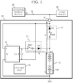
- FIG. 1 is a circuit diagram to illustrate the first embodiment of an uninterruptible power supply unit 10 according to the present invention.
- the uninterruptible power supply unit 10 is a power supply unit that supplies power to a load device 30 to continue the operation of the load device 30 in the event that power cannot be supplied from an external power supply 20 to the load device 30 due to power interruption, etc.
- the uninterruptible power supply unit 10 of the first embodiment includes an input/output terminal 11, a battery unit 12, a DC/DC converter 13, a charging circuit 14, a discharging circuit 15, and a control unit 16.
- the input/output terminal 11 is connected in parallel with a power supply line 21 that supplies power from the external power supply 20 to the load device 30.
- the external power supply 20 is, for example, a power supply unit that converts commercial AC power into a DC power of voltage V1.
- the load device 30 is an electronic instrument that operates with DC power of a voltage V1.
- the battery unit 12 is a battery power supply whose rated voltage is a voltage same as the voltage V1 of the external power supply 20.
- the battery unit 12 includes a battery pack 120 which is constituted by connecting in series or in parallel alkaline secondary batteries such as nickel-hydrogen secondary batteries.
- the battery unit 12 includes a circuit for detecting the voltage and temperature of the battery pack 120 (omitted from illustration).
- the DC/DC converter 13 as a "voltage converter” converts the voltage V1 of the external power supply 20 into a voltage V3 corresponding to a difference between the rated voltage of the battery unit 12 and the charging voltage of the battery unit 12.
- the DC/DC converter 13 is a step-down DC/DC converter of input/output insulation type, which steps down the voltage V1 of the external power supply 20 to the voltage V3.
- a "+" terminal is connected to the input/output terminal 11
- a "-" terminal is connected to the ground.
- a "+" terminal is connected to one end side of a switch SW1 of the charging circuit 14, and a "-" terminal is connected to the input/output terminal 11.
- the charging circuit 14 includes the switch SW1 and a diode D1. To be more specific, the charging circuit 14 is arranged such that one end side of the switch SW1 is connected to the "+" terminal of the output side of the DC/DC converter 13, and the other end side of the switch SW1 is connected to the anode of the diode D1. The cathode of the diode D1 is connected to a positive electrode terminal of the battery unit 12. In the charging circuit 14 of such configuration, turning on the switch SW1 causes the battery unit 12 to be charged with a voltage which is equal to the voltage V1 of the external power supply 20 added with the output voltage V3 of the DC/DC converter 13.
- the discharging circuit 15 includes a switch SW2, and a diode D2.
- the discharging circuit 15 is configured such that one end side of the switch SW2 is connected to the positive electrode terminal of the battery unit 12, and the other end side of the switch SW2 is connected to the anode of the diode D2.
- the cathode of the diode D2 is connected to the input/output terminal 11.
- the control unit 16 is a known microcomputer control device.
- the control unit 16 performs the control such as on/off of the switch SW1 and the switch SW2 based on the voltage V2 and the temperature etc. of the battery unit 12.
- the control unit 16 charges the battery unit 12 to a fully charged state with power of the external power supply 20 during normal time, that is, in a state in which power is being supplied from the external power supply 20 to the load device 30.
- turning on the switch SW1 and turning off the switch SW2 will cause the battery unit 12 to be charged with a voltage equal to the voltage V1 of the external power supply 20 added with the output voltage V3 of the DC/DC converter 13 (symbol A).
- the switch SW1 is turned off.
- the control unit 16 discharges power of the battery unit 12 to the load device 30 through the input/output terminal 11 by turning on the switch SW2 in the event of power interruption (symbol B).
- the charging voltage of the battery unit 12 is a voltage higher than the rated voltage of the battery unit 12, and is also a voltage needed to charge the battery unit 12 to a fully charged state.
- the output voltage V3 of the DC/DC converter 13 corresponds to a difference between the rated voltage of the battery unit 12 and the charging voltage of the battery unit 12.
- the rated voltage of the battery unit 12 is a voltage same as the voltage V1 of the external power supply 20.
- a charging voltage needed to charge a battery cell of nickel-hydrogen secondary battery whose rated voltage is 1.35 V to a fully charged state is about 1.5 V.
- the voltage V1 of the external power supply 20 is assumed to be 54V.
- 40 battery cells of nickel-hydrogen secondary battery whose rated voltage is 1.35 V are connected in series to constitute a battery unit 12 whose rated voltage is 54V which is same as the voltage V1 of the external power supply 20.
- the charging voltage needed to charge the battery unit 12 to a fully charged state is about 60 V (1.5 V x 40). Therefore, it may be specified such that the output voltage V2 of the DC/DC converter 13 is about 6 V.
- the uninterruptible power supply unit 10 according to the present invention is configured such that the battery unit 12 is charged with the charging voltage (voltage V1 + V3) by turning on the switch SW1, it is possible to charge the battery unit 12 to a fully charged state.
- the uninterruptible power supply unit 10 according to the present invention since there is no need of performing time-division charging control as in the conventional art, it is possible to charge the battery unit 12 to a fully charged state in a short time.
- the DC/DC converter 13 steps down the voltage V1 of the external power supply 20 to a voltage V3 corresponding to a difference between the rated voltage of the battery unit 12 and the charging voltage of the battery unit 12. For that reason, the uninterruptible power supply unit 10 according to the present invention can significantly reduce power loss that occurs in the DC/DC converter 13 compared with the conventional art in which the voltage V1 of the external power supply 20 is boosted. Thereby, the uninterruptible power supply unit 10 according to the present invention can significantly reduce heat generation of the DC/DC converter 13 than in the conventional art.
- FIG. 2 A second embodiment of the present invention will be described referring to FIG. 2 .
- FIG. 2 is a circuit diagram to illustrate a second embodiment of the uninterruptible power supply unit 10 according to the present invention.
- the uninterruptible power supply unit 10 of the second embodiment includes, as with the first embodiment, an input/output terminal 11, a battery unit 12, a DC/DC converter 13, a charging circuit 14, a discharging circuit 15, and a control unit 16. Then, the uninterruptible power supply unit 10 of the second embodiment differs from that of the first embodiment in the configurations of the battery unit 12 and the charging circuit 14. Since other components are the same as those of the first embodiment, the same reference symbol is given to the same component and detailed description thereof will be omitted.
- the battery unit 12 of the second embodiment includes a first battery pack 121 and a second battery pack 122 which are connected in series, wherein the rated voltage thereof is a voltage same as the voltage V1 of the external power supply 20.
- a voltage equal to the sum of the voltage of the first battery pack 121 and the voltage of the second battery pack 122 becomes the voltage V2 of the battery unit 12.
- the charging circuit 14 of the second embodiment further includes a switch SW3 and a diode D3 in addition to the switch SW1 and the diode D1.
- the charging circuit 14 is configured such that one end side of the switch SW1 is connected to a "+" terminal on the output side of the DC/DC converter 13, and the other end side of the switch SW1 is connected to the anode of the diode D1.
- the cathode of the diode D1 is connected to the positive electrode terminal of the first battery pack 121.
- An "-" terminal of the output side of the DC/DC converter 13 is connected to the negative electrode of the first battery pack 121.
- the charging circuit 14 is configured such that one end side of the switch SW3 is connected to the input/output terminal 11, and the other end side of the switch SW3 is connected to the anode of the diode D3.
- the cathode of the diode D3 is connected to the positive electrode terminal of the second battery pack 122.
- the charging circuit 14 of such configuration can charge the first battery pack 121 with the output voltage V3 of the DC/DC converter 13, and charges the second battery pack 122 with the voltage V1 of the external power supply 20.
- the charging circuit 14 allows the first battery pack 121 to be charged with the output voltage V3 of the DC/DC converter 13 by turning on the switch SW1.
- the charging circuit 14 allows the second battery pack 122 to be charged with the voltage V1 of the external power supply 20 by turning on the switch SW3.
- the control unit 16 charges the battery unit 12 to a fully charged state with power of the external power supply 20 during normal time, that is, in a state in which power is supplied from the external power supply 20 to the load device 30.
- the SW1 and the switch SW3, and turning off the switch SW2 it becomes possible to charge the first battery pack 121 with the output voltage V3 of the DC/DC converter 13 (symbol C), and charges the second battery pack 122 with the voltage V1 of the external power supply 20 (symbol D).
- the switch SW1 is turned off.
- the switch SW3 is turned off.
- the control unit 16 discharges power of the battery unit 12 to the load device 30 through the input/output terminal 11 by turning on the switch SW2 in the event of power interruption (symbol E).
- the charging voltage needed to charge the battery cell of the nickel-hydrogen secondary battery whose rated voltage is 1.35 V up to a fully charged state will be about 1.5 V.
- the voltage V1 of the external power supply 20 is assumed to be 54 V.
- 40 battery cells of nickel-hydrogen secondary battery whose rated voltage is 1.35 V are connected in series to constitute a battery unit 12 whose rated voltage is 54V which is same as the voltage V1 of the external power supply 20.
- the charging voltage needed to charge the battery unit 12 to a fully charged state will be about 60 V (1.5 V x 40). Therefore, it may be specified such that the output voltage V3 of the DC/DC converter 13 is about 6 V.
- the first battery pack 121 of the battery unit 12 is constituted by connecting in series 4 battery cells of the nickel-hydrogen secondary battery whose rated voltage is 1.35 V, the rated voltage thereof will become 5.4 V.
- the second battery pack 122 of the battery unit 12 will have a rated voltage of 48.6 V if it is constituted by connecting in series the remaining 36 battery cells of the nickel-hydrogen secondary batteries. Since the charging voltage needed to charge the first battery pack 121 whose rated voltage is 5.4 V to be fully charged state is 6 V (1.5 V x 4), it is possible to charge it to a fully charged state with the output voltage V3 (about 6 V) of the DC/DC converter 13.
- the secondary battery pack 122 since the charging voltage needed to charge it to a fully charged state is 54 V (1.5 V x 36), it can be charged to a fully charged state with the voltage V1 (54 V) of the external power supply 20 in parallel with the charging of the first battery pack 121.
- the uninterruptible power supply unit 10 of the second embodiment allows the first battery pack 121 and the second battery pack 122 to be charged with the charging voltage of each (a voltage higher than its rated voltage) by turning on the switch SW1 and the switch SW3.
- the charging of the first battery pack 121 and the charging of the second battery pack 122 can be performed simultaneously in parallel. Since, accordingly, the uninterruptible power supply unit 10 according to the present invention does not need to perform time division charging control as in the conventional art, it can charge the battery unit 12 to a fully charged state in a short time.
- the DC/DC converter 13 steps down the voltage V1 of the external power supply 20 to a voltage V3 corresponding to a difference between the rated voltage of the battery unit 12 and the charging voltage of the battery unit 12. For that reason, the uninterruptible power supply unit 10 according to the present invention can significantly reduce power loss which occurs in the DC/DC converter 13 compared with the conventional art in which the voltage V1 of the external power supply 20 is boosted. Thereby, the uninterruptible power supply unit 10 according to the present invention can significantly reduce the heat generation of the DC/DC converter 13 than in the conventional art.
Landscapes
- Engineering & Computer Science (AREA)
- Power Engineering (AREA)
- Business, Economics & Management (AREA)
- Emergency Management (AREA)
- Charge And Discharge Circuits For Batteries Or The Like (AREA)
- Stand-By Power Supply Arrangements (AREA)
Abstract
Description
- The present invention relates to an uninterruptible power supply unit.
- An uninterruptible power supply unit is a power supply unit that supplies power to a load device from a secondary battery which is charged in advance to allow the load device to continue its operation when power supply to the load device from an external power supply is discontinued due to a power breakdown, etc. It is general that the secondary battery for the uninterruptible power supply unit is charged with power of an external power supply during normal time. As an example of the secondary battery used for the uninterruptible power supply unit, for example, an alkaline secondary battery such as a nickel-hydrogen secondary battery is publicly known.
- An alkaline secondary battery, by its nature, needs to be charged with a voltage higher than its rated voltage. However, in general, in an uninterruptible power supply unit, the rated voltage of the alkaline secondary battery is a voltage same as the voltage of the external power supply. For that reason, it is not possible to charge the alkaline secondary battery to a fully charged state with the power of the external power supply as it is.
- Under these circumstances, an uninterruptible power supply unit equipped with an auxiliary power supply (DC/DC converter) for boosting the voltage of the external power supply is publicly known. To be more specific, when the alkaline secondary battery is charged, the voltage of the external power supply is boosted by an auxiliary power supply and the alkaline secondary battery is charged with the boosted voltage. As a result of this, even if the alkaline secondary battery has a rated voltage which is same as the voltage of the external power supply, it is possible to charge the alkaline secondary battery to a fully charged state with a voltage higher than the rated voltage. Moreover, as an example of technique which utilizes an auxiliary power supply, though which is not an uninterruptible power supply unit, a motor control unit in which the amount of power which can be supplied to an electric motor is increased by the auxiliary power supply when power demand of the electric motor temporarily increases is publicly known (for example, see Patent Document 1).
- However, the conventional art which boosts the voltage of the external power supply with an auxiliary power source, and charges the alkaline secondary battery with the boosted voltage has a problem in that significant power loss occurs during charging. Moreover, in such the conventional art, heat generation of the auxiliary power supply caused by the power loss may lead to a problem in terms of the reliability of the uninterruptible power supply unit. To address such problem, for example, there is publicly known a charging control unit for performing split charging control, in which when a secondary battery including a plurality of unit cells connected in series is charged, some of the plurality of unit cells are selectively connected to a power converter (for example, see Patent Document 2). Since the charging control unit for performing such split charging control selectively charges a plurality of unit cells constituting the secondary battery, it is possible to use a smaller-scale power converter. Since, thereby the charging control unit for performing split charging control can decrease power loss in the power converter, it can reduce the heat generation of the power converter.
-
- Patent Document 1: Japanese Patent Laid-Open No.
2013-110899 - Patent Document 2: Japanese Patent Laid-Open No.
2009-296820 - However, since the charging control unit for performing the above described split charging control performs time-division charging in which a plurality of unit cells constituting the secondary battery are selectively charged, there is a possibility that it takes long hours to charge the secondary battery to a fully charged state.
- The present invention has been made in view of the above described situation, and its objective is to provide an uninterruptible power supply unit which can be charged in a short time without generating much heat.
- A first aspect of the present invention is an uninterruptible power supply unit, comprising: an input/output terminal connected in parallel with a power line for supplying power from an external power supply to a load device; a battery unit whose rated voltage is a voltage same as a voltage of the external power supply; a voltage converter that converts the voltage of the external power supply into a voltage corresponding to a difference between the rated voltage of the battery unit and a charging voltage of the battery unit; a charging circuit that charges the battery unit with a voltage equal to the voltage of the external power supply added with the output voltage of the voltage converter; and a discharging circuit that discharges power from the battery unit to the load device through the input/output terminal in an event that the external power supply is interrupted.
- Here, the charging voltage of the battery unit is a voltage higher than the rated voltage of the battery unit, and a voltage needed for charging the battery unit up to a fully charged state. On the other hand, the voltage of the external power supply is a voltage same as the rated voltage of the battery unit. For that reason, it is not possible to charge the battery unit with the voltage of the external power supply as it is.
- The voltage converter converts the voltage of the external power supply into a voltage corresponding to a difference between the rated voltage of the battery unit and the charging voltage of the battery unit. Then the charging circuit charges the battery unit with a voltage equal to the voltage of the external power supply added with the output voltage of the voltage converter. Since, thereby the battery unit can be charged with the charging voltage of the battery unit, there is no need of performing time-division charging control as in the conventional art. Therefore, it is possible to charge the battery unit up to a fully charged state in a short time.
- Thus, since in the present invention, the voltage of the external power supply is converted into a voltage corresponding to a difference between the rated voltage of the battery unit and the charging voltage of the battery unit, it is possible to significantly reduce power loss which occurs in the voltage converter compared with the conventional art in which the voltage of the external power supply is boosted. Thereby, it is possible to significantly reduce the heat generation of the voltage converter than in the conventional art.
- Thus, the first aspect of the present invention can achieve an advantageous effect that it is possible to provide an uninterruptible power supply unit which can be charged in a short time without generating much heat.
- A second aspect of the present invention is an uninterruptible power supply unit, comprising: an input/output terminal connected in parallel with a power line that supplies power from an external power supply to a load device; a battery unit which includes a first battery pack and a second battery back, which are connected in series, wherein a rated voltage of the battery unit is a voltage same as the voltage of the external power supply; a voltage converter that converts the voltage of the external power supply into a voltage corresponding to a difference between the rated voltage of the battery unit and the charging voltage of the battery unit; a charging circuit that charges the first battery pack with the output voltage of the voltage converter, and charges the second battery pack with the voltage of the external power supply; and a discharging circuit that discharges power from the battery unit to the load device through the input/output terminal in an event that the external power supply is interrupted.
- The voltage converter converts the voltage of the external power supply into a voltage corresponding to a difference between the rated voltage of the battery unit and the charging voltage of the battery unit. Then, the charging unit charges the first battery pack with the output voltage of the voltage converter, and the second battery pack with the voltage of the external power supply. This makes it possible to charge the first battery pack and the second battery pack with the charging voltage of each (voltage higher than the rated voltage). Further, since the charging of the first battery pack and the charging of the second battery pack can be performed in parallel simultaneously, there is no need of performing time-division charging control as in the conventional art. Therefore, it is possible to charge the battery unit to a fully charged state in a short time.
- Further, in the present invention, since the voltage converter converts the voltage of the external power supply into a voltage corresponding to a difference between the rated voltage of the battery unit and the charging voltage of the battery unit, it is possible to significantly reduce power loss which occurs in the voltage converter compared with the conventional art in which the voltage of the external power supply is boosted. As a result, it becomes possible to significantly reduce heat generation of the voltage converter than in the conventional art.
- Thus, the second aspect of the present invention can achieve an advantageous effect that it is possible to provide an uninterruptible power supply unit which can be charged in a short time without generating much heat.
- According to the present invention, it is possible to provide an uninterruptible power supply unit which can be charged in a short time without generating much heat.
-
-
FIG. 1 is a circuit diagram to illustrate a first embodiment of an uninterruptible power supply unit according to the present invention. -
FIG. 2 is a circuit diagram to illustrate a second embodiment of the uninterruptible power supply unit according to the present invention. - Hereinafter, embodiments of the present invention will be described referring to the drawings.
- Note that the present invention will not be limited to embodiments described below, and it is possible without saying to make various modifications within the scope of the invention set forth in the claims of patent.
- A first embodiment of the present invention will be described referring to
FIG. 1 . -
FIG. 1 is a circuit diagram to illustrate the first embodiment of an uninterruptiblepower supply unit 10 according to the present invention. - The uninterruptible
power supply unit 10 is a power supply unit that supplies power to aload device 30 to continue the operation of theload device 30 in the event that power cannot be supplied from anexternal power supply 20 to theload device 30 due to power interruption, etc. - The uninterruptible
power supply unit 10 of the first embodiment includes an input/output terminal 11, abattery unit 12, a DC/DC converter 13, acharging circuit 14, adischarging circuit 15, and acontrol unit 16. - The input/
output terminal 11 is connected in parallel with apower supply line 21 that supplies power from theexternal power supply 20 to theload device 30. Here, theexternal power supply 20 is, for example, a power supply unit that converts commercial AC power into a DC power of voltage V1. Theload device 30 is an electronic instrument that operates with DC power of a voltage V1. - The
battery unit 12 is a battery power supply whose rated voltage is a voltage same as the voltage V1 of theexternal power supply 20. Thebattery unit 12 includes abattery pack 120 which is constituted by connecting in series or in parallel alkaline secondary batteries such as nickel-hydrogen secondary batteries. Moreover, thebattery unit 12 includes a circuit for detecting the voltage and temperature of the battery pack 120 (omitted from illustration). - The DC/
DC converter 13 as a "voltage converter" converts the voltage V1 of theexternal power supply 20 into a voltage V3 corresponding to a difference between the rated voltage of thebattery unit 12 and the charging voltage of thebattery unit 12. To be more specific, the DC/DC converter 13 is a step-down DC/DC converter of input/output insulation type, which steps down the voltage V1 of theexternal power supply 20 to the voltage V3. In the input side of the DC/DC converter 13, a "+" terminal is connected to the input/output terminal 11, and a "-" terminal is connected to the ground. Further, in the output side of the DC/DC converter 13, a "+" terminal is connected to one end side of a switch SW1 of the chargingcircuit 14, and a "-" terminal is connected to the input/output terminal 11. - The charging
circuit 14 includes the switch SW1 and a diode D1. To be more specific, the chargingcircuit 14 is arranged such that one end side of the switch SW1 is connected to the "+" terminal of the output side of the DC/DC converter 13, and the other end side of the switch SW1 is connected to the anode of the diode D1. The cathode of the diode D1 is connected to a positive electrode terminal of thebattery unit 12. In the chargingcircuit 14 of such configuration, turning on the switch SW1 causes thebattery unit 12 to be charged with a voltage which is equal to the voltage V1 of theexternal power supply 20 added with the output voltage V3 of the DC/DC converter 13. - The discharging
circuit 15 includes a switch SW2, and a diode D2. To be more specific, the dischargingcircuit 15 is configured such that one end side of the switch SW2 is connected to the positive electrode terminal of thebattery unit 12, and the other end side of the switch SW2 is connected to the anode of the diode D2. The cathode of the diode D2 is connected to the input/output terminal 11. In the dischargingcircuit 15 of such configuration, turning on the switch SW2 during interruption of the external power supply allows discharge of power from thebattery unit 12 to theload device 30 through the input/output terminal 11. - The
control unit 16 is a known microcomputer control device. Thecontrol unit 16 performs the control such as on/off of the switch SW1 and the switch SW2 based on the voltage V2 and the temperature etc. of thebattery unit 12. - Next, the operation of the uninterruptible
power supply unit 10 will be described further referring toFIG. 1 . - The
control unit 16 charges thebattery unit 12 to a fully charged state with power of theexternal power supply 20 during normal time, that is, in a state in which power is being supplied from theexternal power supply 20 to theload device 30. To be more specific, turning on the switch SW1 and turning off the switch SW2 will cause thebattery unit 12 to be charged with a voltage equal to the voltage V1 of theexternal power supply 20 added with the output voltage V3 of the DC/DC converter 13 (symbol A). Then, after thebattery unit 12 is charged to a fully charged state, the switch SW1 is turned off. On the other hand, thecontrol unit 16 discharges power of thebattery unit 12 to theload device 30 through the input/output terminal 11 by turning on the switch SW2 in the event of power interruption (symbol B). - The charging voltage of the
battery unit 12 is a voltage higher than the rated voltage of thebattery unit 12, and is also a voltage needed to charge thebattery unit 12 to a fully charged state. As described above, the output voltage V3 of the DC/DC converter 13 corresponds to a difference between the rated voltage of thebattery unit 12 and the charging voltage of thebattery unit 12. Also, the rated voltage of thebattery unit 12 is a voltage same as the voltage V1 of theexternal power supply 20. - For example, a charging voltage needed to charge a battery cell of nickel-hydrogen secondary battery whose rated voltage is 1.35 V to a fully charged state is about 1.5 V. Here, the voltage V1 of the
external power supply 20 is assumed to be 54V. Further, 40 battery cells of nickel-hydrogen secondary battery whose rated voltage is 1.35 V are connected in series to constitute abattery unit 12 whose rated voltage is 54V which is same as the voltage V1 of theexternal power supply 20. In this case, the charging voltage needed to charge thebattery unit 12 to a fully charged state is about 60 V (1.5 V x 40). Therefore, it may be specified such that the output voltage V2 of the DC/DC converter 13 is about 6 V. - Since the uninterruptible
power supply unit 10 according to the present invention is configured such that thebattery unit 12 is charged with the charging voltage (voltage V1 + V3) by turning on the switch SW1, it is possible to charge thebattery unit 12 to a fully charged state. As a result, in the uninterruptiblepower supply unit 10 according to the present invention, since there is no need of performing time-division charging control as in the conventional art, it is possible to charge thebattery unit 12 to a fully charged state in a short time. - Moreover, the DC/
DC converter 13 steps down the voltage V1 of theexternal power supply 20 to a voltage V3 corresponding to a difference between the rated voltage of thebattery unit 12 and the charging voltage of thebattery unit 12. For that reason, the uninterruptiblepower supply unit 10 according to the present invention can significantly reduce power loss that occurs in the DC/DC converter 13 compared with the conventional art in which the voltage V1 of theexternal power supply 20 is boosted. Thereby, the uninterruptiblepower supply unit 10 according to the present invention can significantly reduce heat generation of the DC/DC converter 13 than in the conventional art. - Thus, according to the present invention, it is possible to provide an uninterruptible
power supply unit 10 which can be charged in a short time without generating much heat. - A second embodiment of the present invention will be described referring to
FIG. 2 . -
FIG. 2 is a circuit diagram to illustrate a second embodiment of the uninterruptiblepower supply unit 10 according to the present invention. - The uninterruptible
power supply unit 10 of the second embodiment includes, as with the first embodiment, an input/output terminal 11, abattery unit 12, a DC/DC converter 13, a chargingcircuit 14, a dischargingcircuit 15, and acontrol unit 16. Then, the uninterruptiblepower supply unit 10 of the second embodiment differs from that of the first embodiment in the configurations of thebattery unit 12 and the chargingcircuit 14. Since other components are the same as those of the first embodiment, the same reference symbol is given to the same component and detailed description thereof will be omitted. - The
battery unit 12 of the second embodiment includes afirst battery pack 121 and asecond battery pack 122 which are connected in series, wherein the rated voltage thereof is a voltage same as the voltage V1 of theexternal power supply 20. In the second embodiment, a voltage equal to the sum of the voltage of thefirst battery pack 121 and the voltage of thesecond battery pack 122 becomes the voltage V2 of thebattery unit 12. - The charging
circuit 14 of the second embodiment further includes a switch SW3 and a diode D3 in addition to the switch SW1 and the diode D1. To be more specific, the chargingcircuit 14 is configured such that one end side of the switch SW1 is connected to a "+" terminal on the output side of the DC/DC converter 13, and the other end side of the switch SW1 is connected to the anode of the diode D1. The cathode of the diode D1 is connected to the positive electrode terminal of thefirst battery pack 121. An "-" terminal of the output side of the DC/DC converter 13 is connected to the negative electrode of thefirst battery pack 121. Moreover, the chargingcircuit 14 is configured such that one end side of the switch SW3 is connected to the input/output terminal 11, and the other end side of the switch SW3 is connected to the anode of the diode D3. The cathode of the diode D3 is connected to the positive electrode terminal of thesecond battery pack 122. - The charging
circuit 14 of such configuration can charge thefirst battery pack 121 with the output voltage V3 of the DC/DC converter 13, and charges thesecond battery pack 122 with the voltage V1 of theexternal power supply 20. To be more specific, the chargingcircuit 14 allows thefirst battery pack 121 to be charged with the output voltage V3 of the DC/DC converter 13 by turning on the switch SW1. Moreover, the chargingcircuit 14 allows thesecond battery pack 122 to be charged with the voltage V1 of theexternal power supply 20 by turning on the switch SW3. - The
control unit 16 charges thebattery unit 12 to a fully charged state with power of theexternal power supply 20 during normal time, that is, in a state in which power is supplied from theexternal power supply 20 to theload device 30. To be more specific, by turning on the SW1 and the switch SW3, and turning off the switch SW2, it becomes possible to charge thefirst battery pack 121 with the output voltage V3 of the DC/DC converter 13 (symbol C), and charges thesecond battery pack 122 with the voltage V1 of the external power supply 20 (symbol D). Then, after thefirst battery pack 121 is charged to a fully charged state, the switch SW1 is turned off. Moreover, after thesecond battery pack 122 is charged to a fully charged state, the switch SW3 is turned off. On the other hand, thecontrol unit 16 discharges power of thebattery unit 12 to theload device 30 through the input/output terminal 11 by turning on the switch SW2 in the event of power interruption (symbol E). - For example, the charging voltage needed to charge the battery cell of the nickel-hydrogen secondary battery whose rated voltage is 1.35 V up to a fully charged state will be about 1.5 V. Here, the voltage V1 of the
external power supply 20 is assumed to be 54 V. Moreover, 40 battery cells of nickel-hydrogen secondary battery whose rated voltage is 1.35 V are connected in series to constitute abattery unit 12 whose rated voltage is 54V which is same as the voltage V1 of theexternal power supply 20. In this case, the charging voltage needed to charge thebattery unit 12 to a fully charged state will be about 60 V (1.5 V x 40). Therefore, it may be specified such that the output voltage V3 of the DC/DC converter 13 is about 6 V. - Then, if the
first battery pack 121 of thebattery unit 12 is constituted by connecting in series 4 battery cells of the nickel-hydrogen secondary battery whose rated voltage is 1.35 V, the rated voltage thereof will become 5.4 V. Further, thesecond battery pack 122 of thebattery unit 12 will have a rated voltage of 48.6 V if it is constituted by connecting in series the remaining 36 battery cells of the nickel-hydrogen secondary batteries. Since the charging voltage needed to charge thefirst battery pack 121 whose rated voltage is 5.4 V to be fully charged state is 6 V (1.5 V x 4), it is possible to charge it to a fully charged state with the output voltage V3 (about 6 V) of the DC/DC converter 13. Moreover, in the case of thesecondary battery pack 122 whose rated voltage is 48.6 V, since the charging voltage needed to charge it to a fully charged state is 54 V (1.5 V x 36), it can be charged to a fully charged state with the voltage V1 (54 V) of theexternal power supply 20 in parallel with the charging of thefirst battery pack 121. - In this way, the uninterruptible
power supply unit 10 of the second embodiment allows thefirst battery pack 121 and thesecond battery pack 122 to be charged with the charging voltage of each (a voltage higher than its rated voltage) by turning on the switch SW1 and the switch SW3. Thus, the charging of thefirst battery pack 121 and the charging of thesecond battery pack 122 can be performed simultaneously in parallel. Since, accordingly, the uninterruptiblepower supply unit 10 according to the present invention does not need to perform time division charging control as in the conventional art, it can charge thebattery unit 12 to a fully charged state in a short time. - Moreover, the DC/
DC converter 13 steps down the voltage V1 of theexternal power supply 20 to a voltage V3 corresponding to a difference between the rated voltage of thebattery unit 12 and the charging voltage of thebattery unit 12. For that reason, the uninterruptiblepower supply unit 10 according to the present invention can significantly reduce power loss which occurs in the DC/DC converter 13 compared with the conventional art in which the voltage V1 of theexternal power supply 20 is boosted. Thereby, the uninterruptiblepower supply unit 10 according to the present invention can significantly reduce the heat generation of the DC/DC converter 13 than in the conventional art. - Thus, according to the present invention, it is possible to provide an uninterruptible
power supply unit 10 which can be charged in a short time without generating much heat. -
- 10
- Uninterruptible power supply unit
- 11
- Input/output terminal
- 12
- Battery unit
- 13
- DC/DC converter
- 14
- Charging circuit
- 15
- Discharging circuit
- 16
- Control unit
- 20
- External power supply
- 21
- Power supply line
- 30
- Load device
Claims (2)
- An uninterruptible power supply unit, comprising:an input/output terminal connected in parallel with a power line for supplying power from an external power supply to a load device;a battery unit whose rated voltage is a voltage same as a voltage of the external power supply;a voltage converter that converts the voltage of the external power supply into a voltage corresponding to a difference between the rated voltage of the battery unit and a charging voltage of the battery unit;a charging circuit that charges the battery unit with a voltage equal to the voltage of the external power supply added with the output voltage of the voltage converter; anda discharging circuit that discharges power from the battery unit to the load device through the input/output terminal in an event that the external power supply is interrupted.
- An uninterruptible power supply unit, comprising:an input/output terminal connected in parallel with a power line that supplies power from an external power supply to a load device;a battery unit which includes a first battery pack and a second battery back, which are connected in series, and wherein a rated voltage of the battery unit is a voltage same as the voltage of the external power supply;a voltage converter that converts the voltage of the external power supply into a voltage corresponding to a difference between the rated voltage of the battery unit and the charging voltage of the battery unit;a charging circuit that charges the first battery pack with the output voltage of the voltage converter, and charges the second battery pack with the voltage of the external power supply; anda discharging circuit that discharges power from the battery unit to the load device through the input/output terminal in an event that the external power supply is interrupted.
Applications Claiming Priority (2)
| Application Number | Priority Date | Filing Date | Title |
|---|---|---|---|
| JP2014131191A JP6296608B2 (en) | 2014-06-26 | 2014-06-26 | Uninterruptible power system |
| PCT/JP2015/061245 WO2015198687A1 (en) | 2014-06-26 | 2015-04-10 | Uninterruptible power-supply system |
Publications (3)
| Publication Number | Publication Date |
|---|---|
| EP3163712A1 true EP3163712A1 (en) | 2017-05-03 |
| EP3163712A4 EP3163712A4 (en) | 2018-01-10 |
| EP3163712B1 EP3163712B1 (en) | 2022-03-23 |
Family
ID=54937787
Family Applications (1)
| Application Number | Title | Priority Date | Filing Date |
|---|---|---|---|
| EP15812581.5A Not-in-force EP3163712B1 (en) | 2014-06-26 | 2015-04-10 | Uninterruptible power-supply system |
Country Status (5)
| Country | Link |
|---|---|
| US (1) | US10097035B2 (en) |
| EP (1) | EP3163712B1 (en) |
| JP (1) | JP6296608B2 (en) |
| CN (1) | CN106464006B (en) |
| WO (1) | WO2015198687A1 (en) |
Families Citing this family (13)
| Publication number | Priority date | Publication date | Assignee | Title |
|---|---|---|---|---|
| CN213185534U (en) | 2016-05-25 | 2021-05-11 | 米沃奇电动工具公司 | electric equipment |
| KR102500690B1 (en) * | 2017-09-18 | 2023-02-17 | 삼성전자주식회사 | Battery status based charging control method and appratus thereof |
| US20200287400A1 (en) * | 2017-10-09 | 2020-09-10 | Shenzhen Royole Technologies Co. Ltd. | Battery control circuit and electronic device |
| CN107863802B (en) * | 2017-11-23 | 2024-02-20 | 杰华特微电子股份有限公司 | Battery charge and discharge circuit |
| US11489356B2 (en) * | 2019-07-02 | 2022-11-01 | Abb Schweiz Ag | MVDC link-powered battery chargers and operation thereof |
| US11237610B2 (en) * | 2019-11-20 | 2022-02-01 | Intel Corporation | Handling loss of power for uninterruptible power supply efficiency |
| JP7544521B2 (en) * | 2020-07-20 | 2024-09-03 | Fdk株式会社 | Control device, battery pack and power supply device |
| JP7136855B2 (en) * | 2020-08-19 | 2022-09-13 | 矢崎総業株式会社 | Power supply control device, power supply system, power supply control method, and program |
| JP7218071B2 (en) * | 2020-08-19 | 2023-02-06 | 矢崎総業株式会社 | power supply |
| DE102020215598A1 (en) * | 2020-12-10 | 2022-06-15 | Robert Bosch Gesellschaft mit beschränkter Haftung | Charging circuit and method for charging an electrical energy store and electric vehicle |
| GB202116919D0 (en) * | 2021-11-24 | 2022-01-05 | Rolls Royce Plc | Electrical power system |
| CN114243820A (en) * | 2021-12-06 | 2022-03-25 | 上海电气国轩新能源科技有限公司 | Uninterruptible power supply circuit and power supply method thereof |
| US12451718B2 (en) * | 2021-12-21 | 2025-10-21 | Google Llc | Wearable computing device having a charging system for a rechargeable battery |
Family Cites Families (25)
| Publication number | Priority date | Publication date | Assignee | Title |
|---|---|---|---|---|
| JP2776493B2 (en) * | 1994-08-12 | 1998-07-16 | インターナショナル・ビジネス・マシーンズ・コーポレイション | Power supply device for electronic equipment and control method thereof |
| JP3324930B2 (en) * | 1996-05-31 | 2002-09-17 | 富士通株式会社 | Power supply |
| JPH11234915A (en) * | 1998-02-20 | 1999-08-27 | Fujitsu Ltd | Power supply device having rechargeable battery and method of charging / discharging a plurality of batteries |
| US6525666B1 (en) * | 1998-12-16 | 2003-02-25 | Seiko Instruments Inc. | Power circuit |
| TW439342B (en) * | 1999-02-01 | 2001-06-07 | Mitac Int Corp | An external charging/discharging device |
| JP4389387B2 (en) * | 2000-12-28 | 2009-12-24 | 富士電機システムズ株式会社 | Uninterruptible power system |
| TW521468B (en) * | 2001-06-14 | 2003-02-21 | Quanta Comp Inc | Charging apparatus capable of dynamically adjusting charging power |
| KR100793194B1 (en) * | 2001-07-05 | 2008-01-10 | 엘지전자 주식회사 | Multi battery charging method and charging device |
| US7064521B2 (en) * | 2001-08-17 | 2006-06-20 | O2Micro International Limited | Charging circuit for parallel charging in multiple battery systems |
| US7202634B2 (en) * | 2001-08-17 | 2007-04-10 | O2Micro International Limited | Voltage mode, high accuracy battery charger |
| JP2005506817A (en) * | 2001-10-12 | 2005-03-03 | プロトン エネルギー システムズ,インク. | Method and system for controlling and recovering bridge power in a short time to maximize backup power |
| JP4468708B2 (en) * | 2004-01-16 | 2010-05-26 | 三菱電機株式会社 | Power supply |
| JP4709497B2 (en) * | 2004-04-08 | 2011-06-22 | 日立コンピュータ機器株式会社 | Power backup device |
| JP4783644B2 (en) * | 2006-02-07 | 2011-09-28 | 富士通株式会社 | Power control apparatus, server apparatus, and power control method |
| JP4688725B2 (en) * | 2006-05-09 | 2011-05-25 | 三洋電機株式会社 | Power supply |
| US8080900B2 (en) * | 2007-07-18 | 2011-12-20 | Exaflop Llc | Direct-coupled IT load |
| KR100934956B1 (en) * | 2007-09-13 | 2010-01-06 | 한국과학기술연구원 | Self-charging secondary battery by light energy |
| US8450977B2 (en) * | 2007-12-20 | 2013-05-28 | O2Micro, Inc. | Power management systems with charge pumps |
| JP2009296820A (en) | 2008-06-06 | 2009-12-17 | Toyota Motor Corp | Charge controller and charge controlling method for secondary battery, and electric vehicle |
| US8324758B2 (en) * | 2009-03-30 | 2012-12-04 | Encell Technology, Inc. | Parallel power back-up system |
| CA2778404A1 (en) | 2009-10-21 | 2011-04-28 | Morningstar Corporation | Maximum power point tracking bidirectional charge controllers for photovoltaic systems |
| JP2012044801A (en) * | 2010-08-20 | 2012-03-01 | Tokyo Institute Of Technology | Dc/dc converter |
| US8450976B2 (en) * | 2010-10-29 | 2013-05-28 | O2Micro, Inc. | Power topology with battery charging and discharge current protection capabilities |
| JP2013110899A (en) | 2011-11-23 | 2013-06-06 | Bbj Hitech Kk | Electric motor control mechanism with auxiliary power supply |
| JP3183220U (en) * | 2013-02-19 | 2013-05-09 | 株式会社アイケイエス | Power supply |
-
2014
- 2014-06-26 JP JP2014131191A patent/JP6296608B2/en active Active
-
2015
- 2015-04-10 CN CN201580034667.6A patent/CN106464006B/en not_active Expired - Fee Related
- 2015-04-10 US US15/316,457 patent/US10097035B2/en active Active
- 2015-04-10 EP EP15812581.5A patent/EP3163712B1/en not_active Not-in-force
- 2015-04-10 WO PCT/JP2015/061245 patent/WO2015198687A1/en not_active Ceased
Also Published As
| Publication number | Publication date |
|---|---|
| US10097035B2 (en) | 2018-10-09 |
| US20170155276A1 (en) | 2017-06-01 |
| JP2016010288A (en) | 2016-01-18 |
| CN106464006A (en) | 2017-02-22 |
| CN106464006B (en) | 2020-06-02 |
| EP3163712A4 (en) | 2018-01-10 |
| EP3163712B1 (en) | 2022-03-23 |
| WO2015198687A1 (en) | 2015-12-30 |
| JP6296608B2 (en) | 2018-03-20 |
Similar Documents
| Publication | Publication Date | Title |
|---|---|---|
| US10097035B2 (en) | Uninterruptible power supply unit | |
| CN106464005B (en) | Uninterrupted power supply | |
| KR101117706B1 (en) | Power supply apparatus | |
| US20120169124A1 (en) | Output circuit for power supply system | |
| US10017138B2 (en) | Power supply management system and power supply management method | |
| US9331494B2 (en) | Battery system | |
| US20120047725A1 (en) | Facility for forming lithium ion cells | |
| JP2015195674A (en) | Power storage battery assembly control system | |
| JP2012130158A (en) | Power supply device | |
| EP3168961A1 (en) | Uninterruptible power source device | |
| EP4142097A1 (en) | Uninterruptible power supply device | |
| EP4160865A1 (en) | Backup power supply device | |
| JP2009148110A (en) | Charger / discharger and power supply using the same | |
| JP2009296719A (en) | Dc backup power system and method of charging the same | |
| JP2009225516A (en) | Capacitor charging/discharging monitoring control device | |
| EP3651300A1 (en) | Storage battery unit | |
| JP2015080375A (en) | Power conversion device | |
| CN108336779A (en) | Battery module and the battery system for having it | |
| US20160276850A1 (en) | Charging Bus | |
| JP4186218B2 (en) | Secondary battery pack | |
| CN107171393A (en) | a power controller | |
| KR20250063288A (en) | Energy storage apparatus | |
| WO2016175286A1 (en) | Power supply system |
Legal Events
| Date | Code | Title | Description |
|---|---|---|---|
| STAA | Information on the status of an ep patent application or granted ep patent |
Free format text: STATUS: THE INTERNATIONAL PUBLICATION HAS BEEN MADE |
|
| PUAI | Public reference made under article 153(3) epc to a published international application that has entered the european phase |
Free format text: ORIGINAL CODE: 0009012 |
|
| STAA | Information on the status of an ep patent application or granted ep patent |
Free format text: STATUS: REQUEST FOR EXAMINATION WAS MADE |
|
| 17P | Request for examination filed |
Effective date: 20161219 |
|
| AK | Designated contracting states |
Kind code of ref document: A1 Designated state(s): AL AT BE BG CH CY CZ DE DK EE ES FI FR GB GR HR HU IE IS IT LI LT LU LV MC MK MT NL NO PL PT RO RS SE SI SK SM TR |
|
| AX | Request for extension of the european patent |
Extension state: BA ME |
|
| DAV | Request for validation of the european patent (deleted) | ||
| DAX | Request for extension of the european patent (deleted) | ||
| A4 | Supplementary search report drawn up and despatched |
Effective date: 20171207 |
|
| RIC1 | Information provided on ipc code assigned before grant |
Ipc: H02J 7/02 20160101ALI20171201BHEP Ipc: H02M 3/335 20060101ALN20171201BHEP Ipc: H02J 9/06 20060101AFI20171201BHEP Ipc: H02J 7/34 20060101ALI20171201BHEP |
|
| STAA | Information on the status of an ep patent application or granted ep patent |
Free format text: STATUS: EXAMINATION IS IN PROGRESS |
|
| 17Q | First examination report despatched |
Effective date: 20191127 |
|
| GRAP | Despatch of communication of intention to grant a patent |
Free format text: ORIGINAL CODE: EPIDOSNIGR1 |
|
| STAA | Information on the status of an ep patent application or granted ep patent |
Free format text: STATUS: GRANT OF PATENT IS INTENDED |
|
| RIC1 | Information provided on ipc code assigned before grant |
Ipc: H02M 3/335 20060101ALN20211006BHEP Ipc: H02J 7/02 20160101ALI20211006BHEP Ipc: H02J 7/34 20060101ALI20211006BHEP Ipc: H02J 9/06 20060101AFI20211006BHEP |
|
| INTG | Intention to grant announced |
Effective date: 20211021 |
|
| GRAS | Grant fee paid |
Free format text: ORIGINAL CODE: EPIDOSNIGR3 |
|
| GRAA | (expected) grant |
Free format text: ORIGINAL CODE: 0009210 |
|
| STAA | Information on the status of an ep patent application or granted ep patent |
Free format text: STATUS: THE PATENT HAS BEEN GRANTED |
|
| AK | Designated contracting states |
Kind code of ref document: B1 Designated state(s): AL AT BE BG CH CY CZ DE DK EE ES FI FR GB GR HR HU IE IS IT LI LT LU LV MC MK MT NL NO PL PT RO RS SE SI SK SM TR |
|
| REG | Reference to a national code |
Ref country code: GB Ref legal event code: FG4D |
|
| REG | Reference to a national code |
Ref country code: CH Ref legal event code: EP |
|
| REG | Reference to a national code |
Ref country code: DE Ref legal event code: R096 Ref document number: 602015077746 Country of ref document: DE |
|
| REG | Reference to a national code |
Ref country code: IE Ref legal event code: FG4D |
|
| REG | Reference to a national code |
Ref country code: AT Ref legal event code: REF Ref document number: 1478113 Country of ref document: AT Kind code of ref document: T Effective date: 20220415 |
|
| REG | Reference to a national code |
Ref country code: LT Ref legal event code: MG9D |
|
| REG | Reference to a national code |
Ref country code: NL Ref legal event code: MP Effective date: 20220323 |
|
| PG25 | Lapsed in a contracting state [announced via postgrant information from national office to epo] |
Ref country code: SE Free format text: LAPSE BECAUSE OF FAILURE TO SUBMIT A TRANSLATION OF THE DESCRIPTION OR TO PAY THE FEE WITHIN THE PRESCRIBED TIME-LIMIT Effective date: 20220323 Ref country code: RS Free format text: LAPSE BECAUSE OF FAILURE TO SUBMIT A TRANSLATION OF THE DESCRIPTION OR TO PAY THE FEE WITHIN THE PRESCRIBED TIME-LIMIT Effective date: 20220323 Ref country code: NO Free format text: LAPSE BECAUSE OF FAILURE TO SUBMIT A TRANSLATION OF THE DESCRIPTION OR TO PAY THE FEE WITHIN THE PRESCRIBED TIME-LIMIT Effective date: 20220623 Ref country code: LT Free format text: LAPSE BECAUSE OF FAILURE TO SUBMIT A TRANSLATION OF THE DESCRIPTION OR TO PAY THE FEE WITHIN THE PRESCRIBED TIME-LIMIT Effective date: 20220323 Ref country code: HR Free format text: LAPSE BECAUSE OF FAILURE TO SUBMIT A TRANSLATION OF THE DESCRIPTION OR TO PAY THE FEE WITHIN THE PRESCRIBED TIME-LIMIT Effective date: 20220323 Ref country code: BG Free format text: LAPSE BECAUSE OF FAILURE TO SUBMIT A TRANSLATION OF THE DESCRIPTION OR TO PAY THE FEE WITHIN THE PRESCRIBED TIME-LIMIT Effective date: 20220623 |
|
| REG | Reference to a national code |
Ref country code: AT Ref legal event code: MK05 Ref document number: 1478113 Country of ref document: AT Kind code of ref document: T Effective date: 20220323 |
|
| PG25 | Lapsed in a contracting state [announced via postgrant information from national office to epo] |
Ref country code: LV Free format text: LAPSE BECAUSE OF FAILURE TO SUBMIT A TRANSLATION OF THE DESCRIPTION OR TO PAY THE FEE WITHIN THE PRESCRIBED TIME-LIMIT Effective date: 20220323 Ref country code: GR Free format text: LAPSE BECAUSE OF FAILURE TO SUBMIT A TRANSLATION OF THE DESCRIPTION OR TO PAY THE FEE WITHIN THE PRESCRIBED TIME-LIMIT Effective date: 20220624 Ref country code: FI Free format text: LAPSE BECAUSE OF FAILURE TO SUBMIT A TRANSLATION OF THE DESCRIPTION OR TO PAY THE FEE WITHIN THE PRESCRIBED TIME-LIMIT Effective date: 20220323 |
|
| PG25 | Lapsed in a contracting state [announced via postgrant information from national office to epo] |
Ref country code: NL Free format text: LAPSE BECAUSE OF FAILURE TO SUBMIT A TRANSLATION OF THE DESCRIPTION OR TO PAY THE FEE WITHIN THE PRESCRIBED TIME-LIMIT Effective date: 20220323 |
|
| PG25 | Lapsed in a contracting state [announced via postgrant information from national office to epo] |
Ref country code: SM Free format text: LAPSE BECAUSE OF FAILURE TO SUBMIT A TRANSLATION OF THE DESCRIPTION OR TO PAY THE FEE WITHIN THE PRESCRIBED TIME-LIMIT Effective date: 20220323 Ref country code: SK Free format text: LAPSE BECAUSE OF FAILURE TO SUBMIT A TRANSLATION OF THE DESCRIPTION OR TO PAY THE FEE WITHIN THE PRESCRIBED TIME-LIMIT Effective date: 20220323 Ref country code: RO Free format text: LAPSE BECAUSE OF FAILURE TO SUBMIT A TRANSLATION OF THE DESCRIPTION OR TO PAY THE FEE WITHIN THE PRESCRIBED TIME-LIMIT Effective date: 20220323 Ref country code: PT Free format text: LAPSE BECAUSE OF FAILURE TO SUBMIT A TRANSLATION OF THE DESCRIPTION OR TO PAY THE FEE WITHIN THE PRESCRIBED TIME-LIMIT Effective date: 20220725 Ref country code: ES Free format text: LAPSE BECAUSE OF FAILURE TO SUBMIT A TRANSLATION OF THE DESCRIPTION OR TO PAY THE FEE WITHIN THE PRESCRIBED TIME-LIMIT Effective date: 20220323 Ref country code: EE Free format text: LAPSE BECAUSE OF FAILURE TO SUBMIT A TRANSLATION OF THE DESCRIPTION OR TO PAY THE FEE WITHIN THE PRESCRIBED TIME-LIMIT Effective date: 20220323 Ref country code: CZ Free format text: LAPSE BECAUSE OF FAILURE TO SUBMIT A TRANSLATION OF THE DESCRIPTION OR TO PAY THE FEE WITHIN THE PRESCRIBED TIME-LIMIT Effective date: 20220323 Ref country code: AT Free format text: LAPSE BECAUSE OF FAILURE TO SUBMIT A TRANSLATION OF THE DESCRIPTION OR TO PAY THE FEE WITHIN THE PRESCRIBED TIME-LIMIT Effective date: 20220323 |
|
| PG25 | Lapsed in a contracting state [announced via postgrant information from national office to epo] |
Ref country code: PL Free format text: LAPSE BECAUSE OF FAILURE TO SUBMIT A TRANSLATION OF THE DESCRIPTION OR TO PAY THE FEE WITHIN THE PRESCRIBED TIME-LIMIT Effective date: 20220323 Ref country code: IS Free format text: LAPSE BECAUSE OF FAILURE TO SUBMIT A TRANSLATION OF THE DESCRIPTION OR TO PAY THE FEE WITHIN THE PRESCRIBED TIME-LIMIT Effective date: 20220723 Ref country code: AL Free format text: LAPSE BECAUSE OF FAILURE TO SUBMIT A TRANSLATION OF THE DESCRIPTION OR TO PAY THE FEE WITHIN THE PRESCRIBED TIME-LIMIT Effective date: 20220323 |
|
| REG | Reference to a national code |
Ref country code: CH Ref legal event code: PL |
|
| REG | Reference to a national code |
Ref country code: DE Ref legal event code: R097 Ref document number: 602015077746 Country of ref document: DE |
|
| REG | Reference to a national code |
Ref country code: BE Ref legal event code: MM Effective date: 20220430 |
|
| PLBE | No opposition filed within time limit |
Free format text: ORIGINAL CODE: 0009261 |
|
| STAA | Information on the status of an ep patent application or granted ep patent |
Free format text: STATUS: NO OPPOSITION FILED WITHIN TIME LIMIT |
|
| PG25 | Lapsed in a contracting state [announced via postgrant information from national office to epo] |
Ref country code: MC Free format text: LAPSE BECAUSE OF FAILURE TO SUBMIT A TRANSLATION OF THE DESCRIPTION OR TO PAY THE FEE WITHIN THE PRESCRIBED TIME-LIMIT Effective date: 20220323 Ref country code: LU Free format text: LAPSE BECAUSE OF NON-PAYMENT OF DUE FEES Effective date: 20220410 Ref country code: LI Free format text: LAPSE BECAUSE OF NON-PAYMENT OF DUE FEES Effective date: 20220430 Ref country code: DK Free format text: LAPSE BECAUSE OF FAILURE TO SUBMIT A TRANSLATION OF THE DESCRIPTION OR TO PAY THE FEE WITHIN THE PRESCRIBED TIME-LIMIT Effective date: 20220323 Ref country code: CH Free format text: LAPSE BECAUSE OF NON-PAYMENT OF DUE FEES Effective date: 20220430 |
|
| PG25 | Lapsed in a contracting state [announced via postgrant information from national office to epo] |
Ref country code: BE Free format text: LAPSE BECAUSE OF NON-PAYMENT OF DUE FEES Effective date: 20220430 |
|
| 26N | No opposition filed |
Effective date: 20230102 |
|
| PG25 | Lapsed in a contracting state [announced via postgrant information from national office to epo] |
Ref country code: IE Free format text: LAPSE BECAUSE OF NON-PAYMENT OF DUE FEES Effective date: 20220410 |
|
| PGFP | Annual fee paid to national office [announced via postgrant information from national office to epo] |
Ref country code: FR Payment date: 20230309 Year of fee payment: 9 |
|
| PG25 | Lapsed in a contracting state [announced via postgrant information from national office to epo] |
Ref country code: SI Free format text: LAPSE BECAUSE OF FAILURE TO SUBMIT A TRANSLATION OF THE DESCRIPTION OR TO PAY THE FEE WITHIN THE PRESCRIBED TIME-LIMIT Effective date: 20220323 |
|
| PGFP | Annual fee paid to national office [announced via postgrant information from national office to epo] |
Ref country code: GB Payment date: 20230302 Year of fee payment: 9 |
|
| P01 | Opt-out of the competence of the unified patent court (upc) registered |
Effective date: 20230509 |
|
| PG25 | Lapsed in a contracting state [announced via postgrant information from national office to epo] |
Ref country code: IT Free format text: LAPSE BECAUSE OF FAILURE TO SUBMIT A TRANSLATION OF THE DESCRIPTION OR TO PAY THE FEE WITHIN THE PRESCRIBED TIME-LIMIT Effective date: 20220323 |
|
| PGFP | Annual fee paid to national office [announced via postgrant information from national office to epo] |
Ref country code: DE Payment date: 20230228 Year of fee payment: 9 |
|
| PG25 | Lapsed in a contracting state [announced via postgrant information from national office to epo] |
Ref country code: HU Free format text: LAPSE BECAUSE OF FAILURE TO SUBMIT A TRANSLATION OF THE DESCRIPTION OR TO PAY THE FEE WITHIN THE PRESCRIBED TIME-LIMIT; INVALID AB INITIO Effective date: 20150410 |
|
| PG25 | Lapsed in a contracting state [announced via postgrant information from national office to epo] |
Ref country code: MK Free format text: LAPSE BECAUSE OF FAILURE TO SUBMIT A TRANSLATION OF THE DESCRIPTION OR TO PAY THE FEE WITHIN THE PRESCRIBED TIME-LIMIT Effective date: 20220323 Ref country code: CY Free format text: LAPSE BECAUSE OF FAILURE TO SUBMIT A TRANSLATION OF THE DESCRIPTION OR TO PAY THE FEE WITHIN THE PRESCRIBED TIME-LIMIT Effective date: 20220323 |
|
| PG25 | Lapsed in a contracting state [announced via postgrant information from national office to epo] |
Ref country code: TR Free format text: LAPSE BECAUSE OF FAILURE TO SUBMIT A TRANSLATION OF THE DESCRIPTION OR TO PAY THE FEE WITHIN THE PRESCRIBED TIME-LIMIT Effective date: 20220323 |
|
| PG25 | Lapsed in a contracting state [announced via postgrant information from national office to epo] |
Ref country code: MT Free format text: LAPSE BECAUSE OF FAILURE TO SUBMIT A TRANSLATION OF THE DESCRIPTION OR TO PAY THE FEE WITHIN THE PRESCRIBED TIME-LIMIT Effective date: 20220323 |
|
| REG | Reference to a national code |
Ref country code: DE Ref legal event code: R119 Ref document number: 602015077746 Country of ref document: DE |
|
| GBPC | Gb: european patent ceased through non-payment of renewal fee |
Effective date: 20240410 |
|
| PG25 | Lapsed in a contracting state [announced via postgrant information from national office to epo] |
Ref country code: DE Free format text: LAPSE BECAUSE OF NON-PAYMENT OF DUE FEES Effective date: 20241105 |
|
| PG25 | Lapsed in a contracting state [announced via postgrant information from national office to epo] |
Ref country code: GB Free format text: LAPSE BECAUSE OF NON-PAYMENT OF DUE FEES Effective date: 20240410 |
|
| PG25 | Lapsed in a contracting state [announced via postgrant information from national office to epo] |
Ref country code: FR Free format text: LAPSE BECAUSE OF NON-PAYMENT OF DUE FEES Effective date: 20240430 |
|
| PG25 | Lapsed in a contracting state [announced via postgrant information from national office to epo] |
Ref country code: GB Free format text: LAPSE BECAUSE OF NON-PAYMENT OF DUE FEES Effective date: 20240410 Ref country code: FR Free format text: LAPSE BECAUSE OF NON-PAYMENT OF DUE FEES Effective date: 20240430 Ref country code: DE Free format text: LAPSE BECAUSE OF NON-PAYMENT OF DUE FEES Effective date: 20241105 |