EP3163637B1 - Weisses licht abstrahlendes led-modul - Google Patents
Weisses licht abstrahlendes led-modul Download PDFInfo
- Publication number
- EP3163637B1 EP3163637B1 EP16195204.9A EP16195204A EP3163637B1 EP 3163637 B1 EP3163637 B1 EP 3163637B1 EP 16195204 A EP16195204 A EP 16195204A EP 3163637 B1 EP3163637 B1 EP 3163637B1
- Authority
- EP
- European Patent Office
- Prior art keywords
- light
- led chip
- led
- phosphor
- led module
- Prior art date
- Legal status (The legal status is an assumption and is not a legal conclusion. Google has not performed a legal analysis and makes no representation as to the accuracy of the status listed.)
- Active
Links
Images





Classifications
-
- H—ELECTRICITY
- H10—SEMICONDUCTOR DEVICES; ELECTRIC SOLID-STATE DEVICES NOT OTHERWISE PROVIDED FOR
- H10H—INORGANIC LIGHT-EMITTING SEMICONDUCTOR DEVICES HAVING POTENTIAL BARRIERS
- H10H20/00—Individual inorganic light-emitting semiconductor devices having potential barriers, e.g. light-emitting diodes [LED]
- H10H20/80—Constructional details
- H10H20/85—Packages
- H10H20/851—Wavelength conversion means
- H10H20/8511—Wavelength conversion means characterised by their material, e.g. binder
- H10H20/8512—Wavelength conversion materials
- H10H20/8513—Wavelength conversion materials having two or more wavelength conversion materials
-
- H—ELECTRICITY
- H10—SEMICONDUCTOR DEVICES; ELECTRIC SOLID-STATE DEVICES NOT OTHERWISE PROVIDED FOR
- H10H—INORGANIC LIGHT-EMITTING SEMICONDUCTOR DEVICES HAVING POTENTIAL BARRIERS
- H10H20/00—Individual inorganic light-emitting semiconductor devices having potential barriers, e.g. light-emitting diodes [LED]
- H10H20/80—Constructional details
- H10H20/85—Packages
- H10H20/852—Encapsulations
- H10H20/853—Encapsulations characterised by their shape
-
- H—ELECTRICITY
- H10—SEMICONDUCTOR DEVICES; ELECTRIC SOLID-STATE DEVICES NOT OTHERWISE PROVIDED FOR
- H10W—GENERIC PACKAGES, INTERCONNECTIONS, CONNECTORS OR OTHER CONSTRUCTIONAL DETAILS OF DEVICES COVERED BY CLASS H10
- H10W90/00—Package configurations
-
- H—ELECTRICITY
- H10—SEMICONDUCTOR DEVICES; ELECTRIC SOLID-STATE DEVICES NOT OTHERWISE PROVIDED FOR
- H10H—INORGANIC LIGHT-EMITTING SEMICONDUCTOR DEVICES HAVING POTENTIAL BARRIERS
- H10H20/00—Individual inorganic light-emitting semiconductor devices having potential barriers, e.g. light-emitting diodes [LED]
- H10H20/80—Constructional details
- H10H20/882—Scattering means
-
- H—ELECTRICITY
- H10—SEMICONDUCTOR DEVICES; ELECTRIC SOLID-STATE DEVICES NOT OTHERWISE PROVIDED FOR
- H10W—GENERIC PACKAGES, INTERCONNECTIONS, CONNECTORS OR OTHER CONSTRUCTIONAL DETAILS OF DEVICES COVERED BY CLASS H10
- H10W74/00—Encapsulations, e.g. protective coatings
-
- H—ELECTRICITY
- H10—SEMICONDUCTOR DEVICES; ELECTRIC SOLID-STATE DEVICES NOT OTHERWISE PROVIDED FOR
- H10W—GENERIC PACKAGES, INTERCONNECTIONS, CONNECTORS OR OTHER CONSTRUCTIONAL DETAILS OF DEVICES COVERED BY CLASS H10
- H10W90/00—Package configurations
- H10W90/701—Package configurations characterised by the relative positions of pads or connectors relative to package parts
- H10W90/751—Package configurations characterised by the relative positions of pads or connectors relative to package parts of bond wires
- H10W90/753—Package configurations characterised by the relative positions of pads or connectors relative to package parts of bond wires between laterally-adjacent chips
Definitions
- a color point and the color temperature of the white light should be continuously adjustable in a range of 2000-6500K.
- the introduction of phosphor into the LED module should also be simplified.
- the scalability of the LED module towards smaller sizes, in particular light-emitting surfaces, should be easier to achieve.
- Another goal is better color mixing for a more homogeneous white light from the LED module. In this case, in particular, no diffusers should be necessary, which entail a loss of efficiency of the LED module.
- the present invention relates to an LED module that emits white light, having at least one first LED chip and at least one second LED chip, a cover which covers all the LED chips and is provided with at least two different phosphors, with at least one phosphor being added is suitable for converting radiation from the first LED chip at least partially into a first light, at least one other phosphor is suitable for converting radiation from the second LED chip at least partially into a second light, the white light from the LED module converts at least the first and contains the second light, and color coordinates of the white light can be changed by adjusting the intensity and/or wavelength of the radiation of the first and/or second LED chip.
- one or more dams are produced, preferably a ring-shaped dam enclosing all the LED chips is produced, and then the filling with the phosphors preferably distributed therein is filled in as a cover between the dam or dams.
- the selective control of the LED chips with an AM or PWM signal or the selective control by changing the forward current is possible at any time during the operation of the LED module.
- the color point in the CIE diagram or the color temperature of the white light can be continuously changed between at least 2000-6500 K.
- An excitation spectrum of one phosphor advantageously does not overlap with an emission spectrum of the other phosphor.
- the first LED chip is suitable for emitting blue light
- the second LED chip is suitable for emitting UV radiation or violet light
- a first phosphor is suitable for emitting the blue light of the first LED chip and/or the UV radiation or at least partially convert the violet light of the second LED chip into green, greenish-yellow, yellowish-green and/or yellow first light
- a second phosphor is suitable for converting the UV radiation or the violet light of the second LED chip or at least partially convert the blue light of the first LED chip into red second light.
- the LED module that emits white light thus contains at least one phosphor that emits green, greenish-yellow, yellowish-green and/or yellow and one phosphor that emits red. As a result, a pleasantly warm color temperature of the adjustable white light can be achieved.
- the first phosphor is advantageously suitable for only partially converting the blue light of the first LED chip and/or the violet light of the second LED chip into the first light, so that a mixture of the unconverted light and the first light produces a white light results, wherein the white light of the LED module at least the white light consisting of the unconverted light and the contains the first light and the second light.
- the cover is advantageously provided with a third phosphor, the third phosphor being suitable for converting the blue light of the first LED chip and/or the UV radiation or the violet light of the second LED chip at least partially into green, greenish-yellow, to convert yellowish-green and/or yellow third light, and the white light of the LED module contains the third light.
- the third phosphor comprises a rare earth-doped garnet, preferably YAG:Ce 3+ , or LuAG:Ce 3+ , or a rare earth-doped orthosilicate, preferably BOSE
- BOSE means orthosilicates according to the formulas (Ca, Sr, Ba) 2 SiO 4 :Eu 2+ , (Ca, Sr,) 2 SiO 4 :Eu 2+ , Ba 2 SiO 4 :Eu 2+ , Sr 2 SiO 4 :Eu 2+ , (Sr,Ba) 2 SiO 4 :Eu 2+ or (Ca,Ba) 2 SiO 4 :Eu 2+ .
- the color temperature of the white light can be further improved by the additional third phosphor.
- the color rendering index of the light from the LED module is improved if both the blue light from the first LED chip and the UV radiation or the violet light from the second LED chip excite a phosphor that emits green, greenish-yellow, yellowish- emits green and/or yellow light.
- a phosphor that emits green, greenish-yellow, yellowish- emits green and/or yellow light.
- the adjustability of the color point or the color temperature between 2000-6500 K is further simplified.
- the first phosphor comprises a rare earth-doped garnet, preferably YAG:Ce 3+ , or LuAG:Ce 3+ , or a rare earth-doped orthosilicate, preferably BOSE ((Ca, Sr, Ba) 2 SiO 4 :Eu 2 + , (Ca, Sr,) 2 SiO 4 :Eu 2+ , Ba 2 SiO 4 :Eu 2+ , Sr 2 SiO 4 :Eu 2+ , (Sr, Ba) 2 SiO 4 :Eu 2+ ), (Ca , Ba) 2 SiO 4 :Eu 2+ )), and the second phosphor comprises a manganese-doped KSF or a rare earth-doped nitride.
- BOSE ((Ca, Sr, Ba) 2 SiO 4 :Eu 2 + , (Ca, Sr,) 2 SiO 4 :Eu 2+ , Ba 2 SiO 4 :Eu 2+
- the red light of the second Phosphor which can be excited by the blue light of the first LED chip, is then used to shift the color point or the color temperature of the white light of the LED module to a warmer level and to set the color temperature.
- K 2 (SiF 6 ):Mn 4+ or (Sr,Ca)AlSiN 3 :Eu 2+ or CaAlSiN 3 :Eu 2+ can be used for the second phosphor.
- the first LED chip is suitable for emitting blue light with a maximum intensity in a wavelength range of 455 - 475 nm
- the second LED chip is suitable for emitting UV radiation with a maximum intensity in a wavelength range of 230 - to emit 280 nm.
- a blue GaN LED chip and an ultraviolet AlGaN LED chip are used for this LED module.
- the emission wavelength of the AlGaN LED chip is preferably adjustable between 230-280 nm by changing the forward current.
- the cover is advantageously provided with at least one UV-absorbing substance, preferably with TiO 2 and/or Al 2 O 3 .
- the UV absorbing fabric is used to filter unconverted UV radiation that may be undesirable for the human eye.
- the first phosphor comprises a rare earth-doped garnet, preferably YAG:Ce 3+ , or LuAG:Ce 3+ , or a rare earth-doped orthosilicate, preferably BOSE (e.g. (Ba, Sr) 2 SiO 4 :Eu 2 + ), and the second phosphor comprises a rare earth-doped garnet, preferably YAG:Eu 3+ , or a rare earth-doped yttrium oxide, preferably Y 2 O 3 :Eu 3+ .
- BOSE e.g. (Ba, Sr) 2 SiO 4 :Eu 2 +
- the second phosphor comprises a rare earth-doped garnet, preferably YAG:Eu 3+ , or a rare earth-doped yttrium oxide, preferably Y 2 O 3 :Eu 3+
- the first phosphor can convert the light from the blue LED chip and the second phosphor can convert the light from the UV LED chip.
- a YAG:Ce 3+ can be used as the first phosphor, which shows little or no excitation at a wavelength of 230-280 nm (that is to say it is only excited by the blue LED chip).
- Y 2 O 3 :Eu3 + can then be used as the second phosphor, which shows little or no excitation at a wavelength of 455-475 nm (i.e. quasi is only excited by the UV LED chip).
- the main part of the white light of the LED module then comes from the first light, i.e.
- the first and the second LED chip are suitable for emitting UV radiation, with a first phosphor and a second phosphor together being suitable for at least partially converting the UV radiation of the first and second LED chip, respectively, so that a mixture of the first and the second light results in a white light.
- the first LED chip is advantageously suitable for emitting UV radiation with a maximum intensity in a wavelength range of 320-360 nm
- the second LED chip is suitable for emitting UV radiation with a maximum intensity in a wavelength range of 230-280 nm.
- the first phosphor comprises a rare earth-doped garnet, preferably YAG:Ce 3+ or LuAG:Ce 3+ , or a rare earth-doped orthosilicate, preferably BOSE
- the second phosphor comprises a rare earth-doped yttrium oxide , Preferably Y 2 O 3 : Eu 3+
- the LED module also has at least one third LED chip that is suitable for emitting blue light, the white light of the LED module at least the white light consisting of the first and second light and the blue light of the third LED chip.
- the additional blue LED chip is used in such a way that the blue light it emits is essentially unconverted and therefore contributes to the white light of the LED module.
- the third LED chip can in turn be controlled individually, which means that the change in the color point or the color temperature of the white light of the LED module becomes even more variable.
- the color point or the color temperature of the white light of the LED module can be set by specifically controlling the LED chip producing the warmer white light or the LED chip producing the colder white light.
- the first LED chip is suitable for emitting blue light with a maximum intensity in a wavelength range of 400-440 nm
- the second LED chip is suitable for emitting blue light with a maximum intensity in a wavelength range of 430-470 nm.
- Such blue LED chips are easily and cheaply available. It is advantageous that no UV light is emitted.
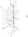
- An inventive white light emitting LED module 1 is in 1 shown.
- the LED module 1 has at least one first LED chip 2 and has at least one second LED chip 3 .
- Four first LED chips 2 and four second LED chips 3 are shown as an example.
- the at least one first LED chip 2 emits radiation of a first wavelength or a first wavelength range
- the at least one second LED -Chip 3 emits radiation of a second wavelength or a second wavelength range.
- the first LED chip 2 is a blue LED chip that emits blue light in a range of 455-475 nm.
- the second LED chip 3 is a violet LED chip emitting violet light in a range of 380-410 nm or, in an unclaimed example, is a UV LED chip emitting UV radiation in a range of preferably emits 230-280 nm.
- the LED module 1 also has a cover 4 which covers all the LED chips 2, 3.
- the cover 4 is a globe top over all the LED chips 2, 3.
- the cover 4 is preferably a globe top dispensed over all the LED chips 2, 3.
- a second phosphor 6 is suitable for at least partially converting the radiation or light emitted by the second LED chip 3 and/or the first LED chip 2 into second light of a fourth wavelength or a fourth wavelength range.
- the second phosphor 6 can also completely convert the light or radiation emitted by the LED chip 3, 2 into the second light convert.
- the second phosphor 6 is a phosphor which, when excited, emits light in the red wavelength range.
- the first phosphor 5 may comprise a rare earth-doped garnet, preferably YAG:Ce 3+ , or LuAG:Ce 3+ , or a rare earth-doped orthosilicate such as BOSE.
- the second phosphor 6 can be a CSF doped with manganese, or a nitride doped with rare earths, or a garnet doped with rare earths, preferably YAG:Eu 3+ , or an yttrium oxide doped with rare earths, preferably Y 2 O 3 :Eu 3+ include. Specific phosphors or advantageous phosphor combinations are shown later in the application.
- FIG. 3 shows a similar LED module 1 as shown in figure 2 is shown.
- the cover 4 which is a globe top.
- This third phosphor 8 is, for example, a garnet doped with rare earths, preferably YAG:Ce 3+ , or LuAG:Ce 3+ , or an orthosilicate doped with rare earths, preferably BOSE, and is excited by the light of the first LED chip 2 or by the light or the UV radiation of the second LED chip 3, preferably green, greenish-yellow, yellowish-green and/or yellow light.
- a similar LED module 1 is shown as in figure 3 is shown.
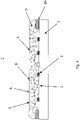
- the cover 4 is now formed as a filling of an LED module 1 produced by insulating and filling.
- the LED module 1 thus formed has at least one dam 8, preferably an annular dam 8 as shown, enclosing the individual LED chips 2, 3 within it. Between the dam 8, the filling with the various phosphors 5, 6, 8 distributed therein is placed over all the LED chips 2,3. It is in 4 It can also be seen that the individual LED chips 2, 3 are connected in series by means of connections routed outside of the dam 8, for example by bonding wires.
- a phosphor mixture is introduced into the cover 4, consisting of a B.O.S.E. phosphor (or alternatively an orthosilicate), a first type of YAG phosphor and KSF.
- the B.O.S.E. phosphor is capable of converting the light from the violet LED chip 3 into greenish yellow light. All phosphors are also suitable for converting the light from the blue LED chip 2 .
- the YAG emits a yellow light
- the B.O.S.E. phosphor emits a greenish-yellow light
- the KSF emits a red light.
- the excitation and emission spectrum of the YAG phosphor used (Y 3 Al 5 O 12 :Ce 3+ ) is in figure 5 shown.
- a LuAG phosphor such as LuAG:Ce 3+
- Excitation and emission spectra for usable BOSE phosphors (BaSrSiO 4 : Eu 2+ ,Ba 2 SiO 4 : Eu 2+ and Sr 2 SiO 4 : Eu 2+ are in the Figures 7-9 shown.
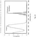
- the excitation and emission spectrum of the used KSF K 2 (SiF 6 ):Mn 4+ ) is in 10 shown.
- a phosphor mixture of a second type of YAG phosphor and KSF is introduced into the cover 4.
- the YAG is capable of converting the light of the violet LED chip 3, particularly into yellowish green light. Both phosphors are also suitable for converting the light from the blue LED chip 3 .
- the YAG emits a yellow light
- the KSF emits a red light.
- the excitation and emission spectrum of the YAG phosphor used (Y 3 Al 5 O 12 :Ce 3+ ) is in 6 shown, the excitation and emission spectrum of the used KSF (K 2 (SiF 6 ):Mn 4+ ) in 10 .
- a phosphor mixture of a BOSE phosphor (alternatively from an orthosilicate), a first type of YAG phosphor and a nitride (e.g. (Sr,Ca)AlSiN 3 :Eu 2+ , CaAlSiN 3 :Eu 2+ ) is used in the cover 4 introduced.
- the BOSE phosphor and the nitride are suitable for converting the light of the violet LED chip 3.
- the BOSE phosphor emits greenish-yellow light in particular, and the nitride emits red light. All three phosphors are suitable for converting the light from the blue LED chip 2 .
- the BOSE phosphor emits greenish-yellow light, the nitride red light and the YAG yellow light.
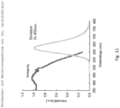
- the excitation and emission spectrum of the YAG phosphor used is in figure 5 shown the excitation and emission spectrum of usable BOSE phosphors (BaSrSiO 4 :Eu 2+ ,Ba 2 SiO 4 :Eu 2+ and Sr 2 SiO 4 :Eu 2+ ) in Figures 7-8 and the excitation and emission spectra of the nitride used (Sr,Ca)AlSiN 3 :Eu 2+ ) in 11 .
- a LuAG phosphor such as LuAG:Ce 3+
- the excitation and emission spectrum of which is in 14 is shown.
- a phosphor mixture is introduced into the cover 4, which consists of a second type of YAG phosphor and a YEO phosphor (alternatively to the YEO phosphor, a third type of YAG phosphor (YAG:Eu 3+ ) consists) .
- Both phosphors are suitable for converting the radiation of the UV LED chip 3, in particular the YAG phosphor of the second type ( 6 ) into yellow light and the YEO phosphor into red light.
- Only the YAG phosphor of the second type is also suitable for converting the light from the blue LED chip 2, namely back into yellow light.
- the absorption and emission spectrum of the YAG phosphor (Y 3 Al 5 O 12 :Ce 3+ ) is in 6 shown, the absorption and emission spectrum of the YEO phosphor (Y 2 O 3 :Eu 3+ ) is in 12 shown.
- the emission and absorption spectrum of the YAG phosphor of the third type (Y 3 Al 5 O 12 :Eu 3+ ), which is an alternative to the YEO phosphor, is in 13 shown.
- a phosphor mixture of a BOSE phosphor, a YEO phosphor (alternatively again a third type YAG phosphor) and a first type of YAG phosphor is introduced.
- the BOSE phosphor and the YEO phosphor (or YAG of the third type) are suitable for converting the radiation from the UV LED chip 3 .
- the BOSE phosphor emits greenish-yellow light and the YEO phosphor (or the YAG of the third type) emits red light away.
- the first-type YAG phosphor and the BOSE phosphor are also suitable for converting the light of the blue LED chip 2 .
- the YAG emits yellow light and the BOSE phosphor greenish-yellow light.
- An unclaimed example of the second embodiment includes a first UV LED chip 2 having an intensity peak at a wavelength of 320-360 nm and a second UV LED chip 3 having an intensity peak at a wavelength range of 230-280 nm .
- a YAG phosphor and a YEO phosphor are used as the phosphor mixture.
- the YAG (YAG:Ce 3+ , figure 5 or 6 ) is particularly suitable for converting the light of the first UV LED chip 2, in particular into yellow light.
- the YEO (Y 2 O 3 :Eu 3+ , 12 ) is suitable for converting the light of the second UV LED chip 3, in particular into red light.
- an LED module 1 that emits white light is realized by the present invention, which can be manufactured more easily, since the various phosphors can be attached more easily.
- the mixing of the different phosphors in a single cover 4, according to the invention a single globe top simplifies the production of the LED module 1 and makes smaller structure sizes more accessible.
- the homogeneity of the white light is also improved.
Landscapes
- Led Device Packages (AREA)
- Luminescent Compositions (AREA)
Description
- Die vorliegende Erfindung betrifft ein weißes Licht abstrahlendes LED-Modul.
- Ferner bezieht sich die vorliegende Erfindung auf ein derartiges LED-Modul, welches hinsichtlich der Farbkoordinaten des von ihm emittierten weißen Lichts veränderbar ist.
- Es ist aus dem Stand der Technik bekannt, weißes Licht eines LED-Moduls aus dem Licht einer roten, einer grünen und einer blauen LED zu mischen. Dabei werden auch Leuchtstoffe oder Leuchtstoffmischungen eingesetzt - und z.B. auf eine oder mehrere der LEDs oder auf Bereiche von LEDs aufgebracht - um wärmeres oder kälteres weißes Licht erzeugen zu können. Außerdem kann abhängig von der Stärke der Ansteuerung der einzelnen LEDs eine Farbtemperatur bzw. ein Farbton des weißen Lichts des bekannten LED-Moduls verändert werden.
- Nachteilig bei diesem weißes Licht abstrahlenden LED-Modul ist, dass es kompliziert und aufwendig ist, die Leuchtstoffe oder Leuchtstoffmischungen präzise auf die LEDs bzw. auf die Bereiche der LEDs aufzubringen. Außerdem ist auch eine Verkleinerung der Lichtabstrahlfläche für dieses LED-Modul nur begrenzt möglich. Zudem kann die Farbtemperatur des LED-Moduls nur in einem relativ engen Bereich und darin nur in diskreten Schritten verändert werden. Auch nachteilig ist, dass die blauen und roten LEDs eine unterschiedliche Temperaturabhängigkeit haben, wodurch der Farbton des LED-Moduls während des Betriebs nicht stabil ist.
- Es ist ferner aus dem Stand der Technik bekannt, weißes Licht eines LED-Moduls aus dem Licht einer kaltweißen LED und einer warmweißen LED zu mischen. Dabei ist jede der LEDs mit einer Abdeckung versehen, insbesondere mit einem Globe-Top über der LED. Ein Globe-Top enthält dabei einen Leuchtstoff zum Erzeugen des kaltweißen Lichts und der andere Globe-Top enthält einen Leuchtstoff zum Erzeugen des warmweißen Lichts. Um die Farbtemperatur bzw. einen Farbpunkt des weißen Lichts des LED-Moduls einzustellen werden die beiden LEDs über einen Treiber mit zwei Ausgangsstufen angesteuert.
- Nachteilig bei diesem weißes Licht abstrahlenden LED-Modul ist, dass das abgestrahlte Licht relativ inhomogen ist und die Homogenität nur mit Hilfe eines Diffusers oder dergleichen gewährleistet werden kann. Weißes Licht abstrahlende LED-Module sind in den Dokumenten
WO 2014/202456 A1 ,EP 2 637 224 A2 ,US 2014/111985 A1 undUS 2011/037081 A1 jeweils offenbart. - Ausgehend von den bekannten LED-Modulen und deren Nachteilen ist es nun Aufgabe der vorliegenden Erfindung, ein verbessertes weißes Licht abstrahlendes LED-Modul herzustellen. Insbesondere sollen ein Farbpunkt und die Farbtemperatur des weißen Lichts in einem Bereich von 2000-6500 K stufenlos einstellbar sein. Das Einbringen von Leuchtstoff in das LED-Modul soll ferner vereinfacht sein. Außerdem soll die Skalierbarkeit des LED-Moduls hin zu kleineren Größen, insbesondere Lichtabstrahlflächen einfacher zu erreichen sein. Ein weiteres Ziel ist eine bessere Farbdurchmischung für ein homogeneres weißes Licht des LED-Moduls. Dabei sollen insbesondere keine Diffusoren notwendig sein, die einen Effizienzverlust des LED-Moduls mit sich bringen.
- Die oben genannten Aufgaben werden durch die vorliegende Erfindung gemäß dem unabhängigen Anspruch gelöst. Weitere vorteilhafte Ausführungsformen der Erfindung werden in den abhängigen Ansprüchen definiert.
- Dabei ist erfindungsgemäß eine einzige Abdeckung über einer LED-Chip Anordnung aus wenigstens zwei LED-Chips vorgesehen, wobei die Abdeckung wenigstens zwei unterschiedliche Leuchtstoffe aufweist.
- Die vorliegende Erfindung betrifft ein weißes Licht abstrahlendes LED-Modul, aufweisend wenigstens einen ersten LED-Chip und wenigstens einen zweiten LED-Chip, eine Abdeckung, welche alle LED-Chips abdeckt und mit wenigstens zwei unterschiedlichen Leuchtstoffen versehen ist, wobei wenigstens ein Leuchtstoff dazu geeignet ist, Strahlung des ersten LED-Chips zumindest teilweise in ein erstes Licht umzuwandeln, wenigstens ein anderer Leuchtstoff dazu geeignet ist, Strahlung des zweiten LED-Chips zumindest teilweise in ein zweites Lichts umzuwandeln, das weiße Licht des LED-Moduls zumindest das erste und das zweite Licht enthält, und Farbkoordinaten des weißen Lichts durch Einstellen der Intensität und/oder Wellenlänge der Strahlung des ersten und/oder zweiten LED-Chips veränderbar sind.
- Dadurch, dass nur eine einzige Abdeckung verwendet wird, die vorzugsweise eine homogene Leuchtstoffschicht über oder Leuchtstoffumhüllung um alle LED-Chips darstellt, kann ein homogeneres weißes Licht aufgrund einer besseren Farbmischung erreicht werden. Dazu ist insbesondere kein Diffuser oder dergleichen nötig. Die einzige im LED-Modul verwendete Abdeckung macht es auch deutlich einfacher die verschiedenen Leuchtstoffe einzubringen. Die verschiedenen Leuchtstoffe müssen insbesondere nicht an gezielten Bereiche angeordnet werden, sondern können gleichverteilt, als Leuchtstoffmischung in die Abdeckung eingebettet werden oder auf diese aufgebracht werden.
- Durch Einstellen der Intensität und/oder Wellenlänge der Strahlung von wenigstens einem LED-Chip ist mit der vorliegenden Erfindung der Farbpunkt - bspw. im CIE-Diagramm - bzw. jede Farbtemperatur des weißen Lichts zwischen 2000-6500 K einstellbar. Um die Intensität und/oder Wellenlänge eines LED-Chips einzustellen bzw. zu vergrößern oder zu verschieben, kann dieser LED-Chip selektiv entweder durchgehend oder gepulst angesteuert werden.
- Die Abdeckung ist ein Globe-Top, vorzugsweise ein über alle LED-Chips dispensierter Globe-Top, oder, in einem nicht beanspruchten Beispiel, ist die Abdeckung eine Füllung eines durch Dämmen-und-Füllen hergestellten LED-Moduls.
- Ein solcher über alle LED-Chips dispensierter Globe-Top, der die wenigstens zwei verschiedenen Leuchtstoffe aufweist, ist einfach herzustellen und auch auf oder über sehr kleinen Lichtabstrahlflächen anzuordnen. Dadurch ist auch eine Verkleinerung des LED-Moduls oder von Lichtabstrahlflächen einfacher möglich. Die verschiedenen Leuchtstoffe lassen sich vorteilhafterweise in dem Material des Globe-Tops verteilen, bevor dieser über die LED-Chips dispensiert wird. Es können alternativ oder zusätzlich auch Leuchtstoffschichten auf dem Globe-Top aufgebracht werden. Dieselben Vorteile sind auch erzielbar für ein LED-Modul, das durch Dämmen und Füllen hergestellt ist. Dabei werden zunächst ein oder mehrere Dämme hergestellt, vorzugsweise wird ein alle LED-Chips umschließender ringförmiger Damm hergestellt, und dann als Abdeckung die Füllung mit den vorzugsweise darin verteilten Leuchtstoffen zwischen den oder die Dämme eingefüllt.
- Vorteilhafterweise ist die Intensität der Strahlung des ersten und/oder zweiten LED-Chips durch Amplituden- oder Pulsweiten-Modulation veränderbar, und/oder ist der Wellenlängenbereich der Strahlung des ersten und/oder zweiten LED-Chips über den Vorwärtsstrom veränderbar.
- Die selektive Ansteuerung der LED-Chips mit einem AM- oder PWM-Signal bzw. die selektive Ansteuerung durch eine Veränderung des Vorwärtsstroms ist gezielt und jederzeit während des Betriebs des LED-Moduls möglich. So kann der Farbpunkt im CIE Diagramm bzw. die Farbtemperatur des weißen Lichts mindestens zwischen 2000-6500 K stufenlos verändert werden.
- Vorteilhafterweise überlappt ein Anregungsspektrum des einen Leuchtstoffs nicht mit einem Emissionsspektrum des anderen Leuchtstoffs.
- Dadurch kann eine separierte Anregung der unterschiedlichen Leuchtstoffe ermöglicht werden. Dies kann beispielweise durch gezielte Lücken im Anregungsspektrum eines oder beider Leuchtstoffe erreicht werden. Zumindest ein Leuchtstoff ist vorteilhafterweise nicht oder nur wenig anregbar durch die Strahlung eines der wenigstens zwei LED-Chips.
- Der erste LED-Chip ist dazu geeignet, blaues Licht auszusenden, der zweite LED-Chip ist dazu geeignet, UV Strahlung oder violettes Licht auszusenden, ein erster Leuchtstoff ist dazu geeignet, das blaue Licht des ersten LED-Chips und/oder die UV Strahlung oder das violette Licht des zweiten LED-Chips zumindest teilweise in grünes, grünlich-gelbes, gelblich-grünes und/oder gelbes erstes Licht umzuwandeln, und ein zweiter Leuchtstoff ist dazu geeignet, die UV Strahlung oder das violette Licht des zweiten LED-Chips oder das blaue Licht des ersten LED-Chips zumindest teilweise in rotes zweites Licht umzuwandeln.
- Das weißes Licht abstrahlende LED-Modul enthält also zumindest einen grün, grünlich-gelb, gelblich-grün und/oder gelb leuchtenden Leuchtstoff und einen rot leuchtenden Leuchtstoff. Dadurch kann eine angenehm warme Farbtemperatur des einstellbaren weißen Lichts erzielt werden.
- Vorteilhafterweise ist der erste Leuchtstoff dazu geeignet, das blaue Licht des ersten LED-Chips und/oder das violette Licht des zweiten LED-Chips nur teilweise in das erste Licht umzuwandeln, so dass eine Mischung des nicht umgewandelten Lichts und des ersten Lichts ein weißes Licht ergibt, wobei das weiße Licht des LED-Moduls zumindest das weiße Licht bestehend aus dem nicht umgewandelten Licht und dem ersten Licht sowie das zweite Licht enthält.
- Der Farbpunkt bzw. die Farbtemperatur des weißen Lichts des LED-Moduls kann nun insbesondere dadurch verändert werden, dass selektiv entweder durchgehend oder beispielsweise in der Art einer PWM-Modulation nur der zweite bzw. der erste LED-Chip angesteuert wird. Dadurch kann die Intensität und/oder Wellenlänge der vom zweiten bzw. ersten LED-Chip abgegebenen Strahlung und somit der Anteil des roten zweiten Lichts eingestellt bzw. verändert werden, wodurch sich der Farbpunkt bzw. die Farbtemperatur des weißen Lichts des LED-Moduls ändert.
- Vorteilhafterweise ist die Abdeckung mit einem dritten Leuchtstoff versehen, wobei der dritte Leuchtstoff dazu geeignet ist, das blaue Licht des ersten LED-Chips und/oder die UV Strahlung oder das violette Licht des zweiten LED-Chips zumindest teilweise in grünes, grünlich-gelbes, gelblich-grünes und/oder gelbes drittes Licht umzuwandeln, und das weiße Licht des LED-Moduls das dritte Licht enthält.
- Vorzugsweise umfasst der dritte Leuchtstoff ein mit seltenen Erden dotiertes Granat, vorzugsweise YAG:Ce3+, oder LuAG:Ce3+, oder ein mit seltenen Erden dotiertes Orthosilikat, vorzugsweise B.O.S.E.
- Unter B.O.S.E. versteht man Orthosilikate gemäß den Formeln (Ca, Sr, Ba)2SiO4:Eu2+, (Ca, Sr,)2SiO4:Eu2+, Ba2SiO4:Eu2+, Sr2SiO4:Eu2+, (Sr, Ba)2SiO4:Eu2+ oder (Ca, Ba)2SiO4:Eu2+.
- Durch den zusätzlichen dritten Leuchtstoff kann die Farbtemperatur des weißen Lichts weiter verbessert werden. Insbesondere wird der Farbwiedergabeindex des Lichts des LED-Moduls verbessert, wenn sowohl das blaue Licht des ersten LED-Chips als auch die UV Strahlung bzw. das violette Licht des zweiten LED-Chips einen Leuchtstoff anregen, der grünes, grünlich-gelbes, gelblich-grünes und/oder gelbes Licht abgibt. In anderen Worten, wenn das Licht bzw. die Strahlung aus beiden LED-Chips zumindest zum Teil in grünes, grünlich-gelbes, gelblich-grünes und/oder gelbes Licht umgewandelt wird. Dies kann durch einen breitbandig anregbaren Leuchtstoff oder durch zwei verschiedene, unterschiedlich anregbare Leuchtstoffe realisiert werden. Ferner wird auch die Einstellbarkeit des Farbpunkts bzw. der Farbtemperatur zwischen 2000-6500 K weiter vereinfacht.
- Wenigstens zwei Leuchtstoffe, bspw. der erste oder zweite Leuchtstoff und der dritte Leuchtstoff, können vorteilhafterweise durch einen einzigen Leuchtstoff realisiert werden. Das bedeutet es kann ein spezieller Leuchtstoff verwendet werden, der bspw. sowohl durch blaues Licht als auch durch violettes Licht oder UV-Strahlung anregbar ist. Dies verringert die Komplexität des Systems und ist beispielsweise durch eine gezielte Dotierung eines bekannten YAG-Leuchtstoffs mit einer seltenen Erde wie z.B. Ce3+ möglich.
- Der erste LED-Chip ist dazu geeignet, blaues Licht mit einem Intensitätsmaximum in einem Wellenlängenbereich von 455 - 475 nm auszusenden, und ist der zweite LED-Chip dazu ist geeignet, violettes Licht mit einem Intensitätsmaximum in einem Wellenlängenbereich von 380 - 410 nm, vorzugsweise bei einer Wellenlänge von etwa 405 nm, auszusenden.
- Ein derartiges LED-Modul hat den Vorteil, dass die einzelnen LED-Chips einfach und billig verfügbar sind. Insbesondere können der erste und zweite LED-Chip auf GaN basierte LED-Chips sein. Des Weiteren sind für solche LED-Chips auch geeignete Leuchtstoffe zur Umsetzung der vorliegenden Erfindung gut verfügbar.
- Vorteilhafterwiese umfasst der erste Leuchtstoff ein mit seltenen Erden dotiertes Granat, vorzugsweise YAG:Ce3+, oder LuAG:Ce3+, oder ein mit seltenen Erden dotiertes Orthosilikat, vorzugsweise B.O.S.E. ((Ca, Sr, Ba)2SiO4:Eu2+, (Ca, Sr,)2SiO4:Eu2+, Ba2SiO4:Eu2+, Sr2SiO4:Eu2+, (Sr, Ba)2SiO4:Eu2+), (Ca, Ba)2SiO4:Eu2+)), und umfasst der zweite Leuchtstoff ein mit Mangan dotiertes KSF oder ein mit seltenen Erden dotiertes Nitrid.
- In diesem Fall kann der erste Leuchtstoff das Licht des violetten LED-Chips und der zweite Leuchtstoff das Licht des blauen LED-Chips wenigstens zum Teil umwandeln. Wird beispielsweise ein Orthosilikat, etwa nach einer der Formel (Ca, Sr, Ba)2SiO4:Eu2+, (Ca, Sr,)2SiO4:Eu2+, Ba2SiO4:Eu2+, Sr2SiO4:Eu2+, (Sr, Ba)2SiO4:Eu2+), (Ca, Ba)2SiO4:Eu2+) als erster Leuchtstoff verwendet, der durch das violette Licht des zweiten LED-Chips anregbar ist, so kann bereits durch den violetten LED-Chip und den ersten Leuchtstoff ein weißes Licht erzeugt werden. Das rote Licht des zweiten Leuchtstoffs, der durch das blaue Licht des ersten LED-Chips anregbar ist, dient dann dazu, den Farbpunkt bzw. die Farbtemperatur des weißen Lichts des LED-Moduls ins wärmere zu verschieben und die Farbtemperatur einzustellen. Beispielsweise kann für den zweiten Leuchtstoff K2(SiF6):Mn4+ oder (Sr, Ca)AlSiN3:Eu2+ oder CaAlSiN3:Eu2+ verwendet werden.
- In einem nicht beanspruchten Beispiel ist der erste LED-Chip dazu geeignet, blaues Licht mit einem Intensitätsmaximum in einem Wellenlängenbereich von 455 - 475 nm auszusenden, und ist der zweite LED-Chip dazu geeignet, UV Strahlung mit einem Intensitätsmaximum in einem Wellenlängenbereich von 230 - 280 nm auszusenden.
- Für dieses LED-Modul wird beispielsweise ein blauer GaN LED-Chip und ein ultravioletter AlGaN LED-Chip verwendet. Die Emissionswellenlänge des AlGaN LED-Chips ist vorzugsweise durch Veränderung des Vorwärtsstroms zwischen 230-280 nm einstellbar.
- Vorteilhafterweise ist die Abdeckung mit wenigstens einem UV-absorbierenden Stoff versehen, vorzugsweise mit TiO2 und/oder Al2O3.
- Der UV absorbierende Stoff wird eingesetzt, um nicht umgewandelte UV-Strahlung zu filtern, die unter Umständen ungewünscht für das menschliche Auge sein kann. Vorteilhafterweise umfasst der erste Leuchtstoff ein mit seltenen Erden dotiertes Granat, vorzugsweise YAG:Ce3+, oder LuAG:Ce3+, oder ein mit seltenen Erden dotiertes Orthosilikat, vorzugsweise B.O.S.E. (bspw. (Ba, Sr)2SiO4:Eu2+), und umfasst der zweite Leuchtstoff ein mit seltenen Erden dotiertes Granat, vorzugsweise YAG:Eu3+, oder ein mit seltenen Erden dotiertes Yttrium-Oxid, vorzugsweise Y2O3:Eu3+.
- In diesem Fall kann der erste Leuchtstoff das Licht des blauen LED-Chips und der zweite Leuchtstoff das Licht des UV LED-Chips umwandeln. Beispielsweise kann als erster Leuchtstoff ein YAG:Ce3+verwendet werden, der bei einer Wellenlänge von 230-280 nm keine bzw. nur wenig Anregung zeigt (also quasi nur durch den blauen LED-Chip angeregt wird). Als zweiter Leuchtstoff kann dann Y2O3:Eu3+ verwendet, das bei einer Wellenlänge von 455-475 nm keine bzw. nur wenig Anregung zeigt (also quasi nur durch den UV LED-Chip angeregt wird). Der Hauptanteil des weißen Lichts des LED-Moduls stammt dann durch das erste Licht, also dem blauen Licht des ersten LED-Chips und dem grünen bzw. gelben Licht des YAG:Ce3+, während eine Farbverschiebung ins rötliche durch das Licht abgegeben vom Y2O3:Eu3+ erreicht wird. Je nach Ansteuerung der einzelnen LEDs-Chips kann eine solche Lichtüberlagerung verändert werden, um einen Farbpunkt bzw. eine Farbtemperatur des weißen Lichts des LED-Moduls einzustellen.
- In einem nicht beanspruchten Beispiel ist der erste und der zweite LED-Chip dazu geeignet, UV Strahlung auszusenden, wobei ein erster Leuchtstoff und ein zweiter Leuchtstoff zusammen dazu geeignet sind, die UV Strahlung des ersten bzw. zweiten LED-Chips zumindest teilweise umzuwandeln, so dass eine Mischung aus dem ersten und dem zweiten Licht ein weißes Licht ergibt.
- Vorteilhafterweise ist der erste LED-Chip dazu geeignet, UV Strahlung mit einem Intensitätsmaximum in einem Wellenlängenbereich von 320 - 360 nm auszusenden, und ist der zweite LED-Chip dazu geeignet, UV Strahlung mit einem Intensitätsmaximum in einem Wellenlängenbereich von 230 - 280 nm auszusenden. Vorteilhafterweise umfasst der erste Leuchtstoff ein mit seltenen Erden dotiertes Granat, vorzugsweise YAG:Ce3+, oder LuAG:Ce3+, oder ein mit seltenen Erden dotiertes Orthosilikat, vorzugsweise B.O.S.E., und umfasst der zweite Leuchtstoff ein mit seltenen Erden dotiertes Yttrium-Oxid, vorzugsweise Y2O3:Eu3+, Vorteilhafterweise weist das LED-Modul ferner wenigstens einen dritten LED-Chip auf, der dazu geeignet ist, blaues Licht auszusenden, wobei das weiße Licht des LED-Moduls zumindest das weiße Licht bestehend aus dem ersten und dem zweiten Lichts sowie das blaue Licht des dritten LED-Chips enthält.
- Der zusätzliche blaue LED-Chip wird derart verwendet, dass das von ihm abgegebene blaue Licht im Wesentlichen nicht umgewandelt wird und deshalb zu dem weißen Licht des LED-Moduls beiträgt. Der dritte LED-Chip kann wiederum einzeln angesteuert werden, wodurch die Veränderung des Farbpunktes bzw. der Farbtemperatur des weißen Lichts des LED-Moduls noch variabler wird.
- In einem nicht beanspruchten Beispiel ist der erste und der zweite LED-Chip dazu geeignet, blaues Licht auszusenden, wobei der erste Leuchtstoff dazu geeignet ist, das blaue Licht des ersten LED-Chips nur teilweise umzuwandeln, so dass eine Mischung aus dem nicht umgewandelten blauen Licht des ersten LED-Chips und dem ersten Licht ein wärmeres weißes Licht ergibt, wobei der zweite Leuchtstoff dazu geeignet ist, das blaue Licht des zweiten LED-Chips nur teilweise umzuwandeln, so dass eine Mischung aus dem nicht umgewandelten blauen Licht des zweiten LED-Chips und dem zweiten Licht ein kälteres weißes Licht ergibt, und wobei das weiße Licht des LED-Moduls zumindest das wärmere und das kältere weiße Licht enthält.
- Durch gezielte Ansteuerung des das wärmere weiße Licht produzierenden LED-Chips bzw. des das kältere weiße Licht produzierenden LED-Chips kann der Farbpunkt bzw. die Farbtemperatur des weißen Lichts des LED-Moduls eingestellt werden.
- Vorteilhafterweise ist der erste LED-Chip dazu geeignet, blaues Licht mit einem Intensitätsmaximum in einem Wellenlängenbereich von 400 - 440 nm auszusenden, und ist der zweite LED-Chip dazu geeignet, blaues Licht mit einem Intensitätsmaximum in einem Wellenlängenbereich von 430 - 470 nm auszusenden. Derartige blaue LED-Chips sind einfach und billig erhältlich. Vorheilhaft ist, dass auch keinerlei UV-Licht abgegeben wird.
- Die vorliegende Erfindung wird nun detailliert im Bezug auf die beigefügten Figuren beschrieben.
-
Figur 1 zeigt ein LED-Modul gemäß der vorliegenden Erfindung. -
Figur 2 zeigt ein LED-Modul mit zwei Leuchtstoffen in einem Globe-Top gemäß der vorliegenden Erfindung. -
Figur 3 zeigt ein LED-Modul mit drei Leuchtstoffen in einem Globe-Top gemäß der vorliegenden Erfindung. -
Figur 4 ein durch Dämmen und Füllen hergestelltes LED-Modul. -
Figur 5 zeigt ein Anregungs- und Emissionsspektrum eines ersten YAG-Leuchtstoffs. -
Figur 6 zeigt ein Anregungs- und Emissionsspektrum eines zweiten YAG-Leuchtstoffs. -
Figur 7 zeigt ein Anregungs- und Emissionsspektrum eines B.O.S.E.-Leuchtstoffs. -
Figur 8 zeigt ein Anregungs- und Emissionsspektrum eines B.O.S.E.-Leuchtstoffs. -
Figur 9 zeigt ein Anregungs- und Emissionsspektrum Orthosilikat-Leuchtstoffs. - Figur zeigt 10 ein Anregungs- und Emissionsspektrum eines KSF-Leuchtstoffs.
-
Figur 11 zeigt ein Anregungs- und Emissionsspektrum eines mit seltenen Erden dotierten Nitrid-Leuchtstoffs. -
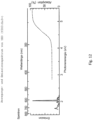
Figur 12 zeigt ein Anregungs- und Emissionsspektrum eines mit seltenen Erden dotierten YEO-Leuchtstoffs (Yttrium-Oxid). -
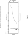
Figur 13 zeigt ein Anregungs- und Emissionsspektrum eines dritten YAG-Leuchtstoffs. -
Figur 14 zeigt ein Anregungs- und Emissionsspektrum eines LUAG-Leuchtstoffs. - Ein erfindungsgemäßes weißes Licht abstrahlendes LED-Modul 1 ist in
Fig. 1 gezeigt. - Das LED-Modul 1 weist zumindest einen ersten LED-Chip 2 auf und weist zumindest einen zweiten LED-Chip 3 auf. Gezeigt sind beispielhaft vier erste LED-Chips 2 und vier zweite LED-Chips 3. Der wenigstens eine erste LED-Chip 2 sendet im Betrieb des LED-Moduls 1 Strahlung einer ersten Wellenlänge bzw. eines ersten Wellenlängenbereichs aus, während der wenigstens eine zweite LED-Chip 3 Strahlung einer zweiten Wellenlänge bzw. eines zweiten Wellenlängenbereichs aussendet.
- Der erste LED-Chip 2 ist ein blauer LED-Chip, der blaues Licht in einem Bereich von 455-475 nm aussendet. Der zweite LED-Chip 3 ist ein violetter LED-Chip, der violettes Licht in einem Bereich von 380-410 nm aussendet, oder, in einem nicht beanspruchten Beispiel, ist ein UV LED-Chip, der UV-Strahlung in einem Bereich von vorzugsweise 230-280 nm aussendet.
- Das LED-Modul 1 weist ferner eine Abdeckung 4 auf, welche alle LED-Chips 2, 3, abdeckt. In
Fig. 1 ist die Abdeckung 4 ein Globe-Top über alle LED-Chips 2, 3. - Vorzugsweise ist die Abdeckung 4 in diesem Fall ein über alle LED-Chips 2, 3 dispensierter Globe-Top.
- Die Abdeckung 4 ist zumindest mit einem ersten Leuchtstoff 5 und einem zweiten Leuchtstoff 6 versehen (bspw. versetzt, vermischt oder überzogen), die Abdeckung 4 weist also wenigstens zwei unterschiedliche Leuchtstoffe 5, 6 auf. Die Abdeckung 4 ist dabei vorzugsweise homogen mit den beiden Leuchtstoffen 5, 6 versehen, insbesondere homogen über alle LED-Chips 2,3 bzw. deren Abstrahlwinkel. Wenigstens einer der Leuchtstoffe 5, 6 ist dazu geeignet Strahlung des ersten LED-Chips 2 zumindest teilweise in ein erstes Licht umzuwandeln und wenigstens ein anderer Leuchtstoff 5, 6 ist dazu geeignet, Strahlung des zweiten LED-Chips 3 zumindest teilweise in ein zweites Lichts umzuwandeln
- Ein erster Leuchtstoff 5 ist dazu geeignet, das von dem ersten LED-Chip 2 und/oder zweiten LED-Chip 3 ausgesandte Licht zumindest teilweise in erstes Licht einer dritten Wellenlänge bzw. eines dritten Wellenlängenbereichs umzuwandeln. Der Leuchtstoff kann das vom LED-Chip 2, 3 abgegebene Licht auch komplett in das erste Licht umwandeln. Dazu ist der erste Leuchtstoff 5 ein Leuchtstoff, der im grünen, grünlich-gelben, gelblich-grünen und/oder gelben Wellenlängenbereich (also etwa zwischen etwa 510-580 nm) auf Anregung hin abstrahlt.
- Ein zweiter Leuchtstoff 6 ist dazu geeignet, die von dem zweiten LED-Chip 3 und/oder die von dem ersten LED-Chip 2 abgegebene Strahlung bzw. Licht zumindest teilweise in zweites Licht einer vierten Wellenlänge bzw. eines vierten Wellenlängenbereichs umzuwandeln. Der zweite Leuchtstoff 6 kann das vom LED-Chip 3, 2 ausgesandte Licht bzw. Strahlung auch komplett in das zweite Licht umwandeln. Der zweite Leuchtstoff 6 ist ein Leuchtstoff, der auf Anregung hin ein Licht im roten Wellenlängenbereich abgibt.
- Das insgesamt vom LED-Modul 1 abgegebene Licht enthält dann zumindest das erste Licht, welches von dem ersten Leuchtstoff 5 abgegeben wird, und das zweite Licht, welches von dem zweiten Leuchtstoff 6 abgegeben wird. Dadurch wird ein warmes weißes Licht erzielt. Wandeln die Leuchtstoffe 5, 6 entweder beide oder wenigstens einer von ihnen das Anregungslicht nicht komplett um, so mischt sich zu dem weißen Licht des LED-Moduls 1 noch die vom ersten LED-Chip 2 abgegebene Strahlung bzw. die vom zweiten LED-Chip 3 abgegebene Strahlung.
- In
Fig. 1 sind Anschlüsse an die LED-Chips 2, 3 gezeigt, mit denen die LED-Chips 2,3 entweder individuell oder gemeinschaftlich ansteuerbar sind. Insbesondere ist das LED-Modul 1 mit entsprechenden Einrichtungen versehen, um die LEDs 2, 3 - entweder einzeln oder alle zusammen - durch Amplituden-Modulation (AM-Modulation) oder durch Pulsweiten-Modulation (PWM-Modulation) anzusteuern, oder einen Vorwärtsstrom durch die LED-Chips 2, 3 zu verändern. Dadurch ist es möglich, die Intensität der Strahlung der einzelnen LED-Chips 2, 3 bzw. eine Wellenlänge der Strahlung (bzw. einen Wellenlängenbereich) der einzelnen LED-Chips 2, 3 gezielt zu verändern. Durch diese gezielte Veränderung können die Farbkoordinaten des LED-Moduls 1, der Farbpunkt in einem Farbdiagramm wie CIE-Diagramm und/oder die Farbtemperatur des weißen Lichts des LED-Modul 1, in einem Bereich von wenigstens 2000-6500 K stufenlos eingestellt werden. InFig. 2 sind die einzelnen LED-Chips 2, 3 auf einer Basisplatte 7, beispielsweise einem FR4 PCB angeordnet. -
Fig. 2 zeigt ein ähnliches weißes Licht abstrahlendes LED-Modul 1 wie es inFigur 1 gezeigt ist. In der Abdeckung 4, die inFig. 2 auch ein Globe-Top ist, sind zwei verschiedenen Leuchtstoffe 5 bzw. 6 gezeigt. - Der erste Leuchtstoff 5 kann ein mit seltenen Erden dotiertes Granat, vorzugsweise YAG:Ce3+, oder LuAG:Ce3+, oder ein mit seltenen Erden dotiertes Orthosilikat, wie beispielsweise B.O.S.E., umfassen. Der zweite Leuchtstoff 6 kann ein mit Mangan dotiertes KSF, oder ein mit seltenen Erden dotiertes Nitrid, oder ein mit seltenen Erden dotiertes Granat vorzugsweise YAG:Eu3+, oder ein mit seltenen Erden dotiertes Yttrium-Oxid, vorzugsweise Y2O3:Eu3+ umfassen. Spezifische Leuchtstoffe bzw. vorteilhafte Leuchtstoffkombinationen werden später in der Anmeldung gezeigt.
-
Fig. 3 zeigt ein ähnliches LED-Modul 1, wie es inFigur 2 gezeigt ist. InFig. 3 ist zusätzlich zu dem ersten Leuchtstoff 5 und dem zweiten Leuchtstoff 6 noch ein dritter Leuchtstoff 8 in der Abdeckung 4 vorhanden, die ein Globe-Top ist. - Dieser dritte Leuchtstoff 8 ist beispielsweise ein mit seltenen Erden dotiertes Granat, vorzugsweise YAG:Ce3+, oder LuAG:Ce3+, oder ein mit seltenen Erden dotiertes Orthosilikat, vorzugsweise B.O.S.E., und gibt auf Anregung durch das Licht des ersten LED-Chips 2 oder durch das Licht bzw. die UV Strahlung des zweiten LED-Chips 3 vorzugsweise grünes, grünlich-gelbes, gelblich-grünes und/oder gelbes Licht ab.
- In
Fig. 4 ist ein ähnliches LED-Modul 1 gezeigt, wie es inFigur 3 gezeigt ist. Die Abdeckung 4 ist allerdings nun als Füllung eines durch Dämmen und Füllen hergestellten LED-Moduls 1 gebildet. Das derart gebildete LED-Modul 1 weist wenigstens einen Damm 8 auf, vorzugsweise wie gezeigt einen ringförmigen Damm 8, der die einzelnen LED-Chips 2, 3 in seinem inneren einschließt. Zwischen den Damm 8 ist über alle LED-Chips 2,3 die Füllung mit den darin verteilten verschiedenen Leuchtstoffen 5, 6, 8 eingebracht. Es ist inFig. 4 auch zu sehen, dass die einzelnen LED-Chips 2, 3 mittels nach außerhalb des Damms 8 geleiteter Anschlüsse durch beispielsweise Bonddrähte in Serie verschaltet sind. - Die Basisplatte 7 ist vorzugsweise eine Alanod-Platte, oder eine andere hoch-reflektierende Platte 7, um das Licht der einzelnen LED-Chips 2, 3 bzw. von den Leuchtstoffen 5, 6, 8 zurückgestreutes Licht wieder zu reflektieren, um die Lichtabgabe des LED-Moduls 1 zu erhöhen. Eine solche hoch-reflektierende Platte 7 ist auch für alle gezeigten LED-Module 1 mit Globe-Top als Abdeckung 4 möglich.
- Im Folgenden werden nun Beispiele für die oben genannten Ausführungsformen mit besonders vorteilhaften Kombinationen von LED-Chips und Leuchtstoffen beschreiben.
- Eine erstes, zweites und drittes Beispiel für die erste Variante der ersten Ausführungsform umfasst jeweils wenigstens einen blauen LED-Chip 2, der ein Intensitätsmaximum in einem Wellenlängenbereich von 455-475 nm aufweist, und wenigstens einen violetten LED-Chip 3, der einen Intensitätsmaximum in einem Wellenlängenbereich von 380-410 nm aufweist.
- Im ersten Beispiel wird eine Leuchtstoffmischung in die Abdeckung 4 eingebracht, die aus einem B.O.S.E.-Leuchtstoff (oder alternativ einem Orthosilikat), einer ersten Art von YAG-Leuchtstoff und KSF besteht. Der B.O.S.E.-Leuchtstoff ist dazu geeignet, das Licht des violetten LED-Chips 3 in grünlich-gelbes Licht umzuwandeln. Alle Leuchtstoffe sind ferner dazu geeignet, das Licht des blauen LED-Chips 2 umzuwandeln. Der YAG gibt dabei insbesondere ein gelbes Licht ab, der B.O.S.E.-Leuchtstoff gibt ein grünlich-gelbes Licht ab und das KSF gibt ein rotes Licht ab.
- Das Anregungs- und Emissionsspektrum des verwendeten YAG-Leuchtstoffs (Y3Al5O12:Ce3+) ist in
Fig. 5 gezeigt. Alternativ zu dem YAG-Leuchtstoff kann ein LuAG-Leuchtstoff (etwa LuAG:Ce3+) verwendet werden, dessen Anregungs- und Emissionsspektrum inFig. 14 gezeigt ist. Anregung- und Emissionsspektren für verwendbare B.O.S.E.-Leuchtstoffe (BaSrSiO4: Eu2+,Ba2SiO4: Eu2+ und Sr2SiO4: Eu2+sind in denFig. 7 -9 gezeigt. Das Anregungs- und Emissionsspektrum des verwendeten KSF (K2(SiF6):Mn4+) ist inFig. 10 gezeigt. - Im zweiten Beispiel wird eine Leuchtstoffmischung aus einer zweiten Art von YAG-Leuchtstoff und KSF in die Abdeckung 4 eingebracht. Der YAG ist dazu geeignet, das Licht des violetten LED-Chips 3 umzuwandeln, insbesondere in gelblich-grünes Licht. Beide Leuchtstoffe sind ferner dazu geeignet, das Licht des blauen LED-Chips 3 umzuwandeln. Der YAG gibt dabei insbesondere ein gelbes Licht ab, das KSF gibt ein rotes Licht ab.
- Das Anregungs- und Emissionsspektrum des verwendeten YAG-Leuchtstoffs (Y3Al5O12:Ce3+) ist in
Fig. 6 gezeigt, das Anregungs- und Emissionsspektrum des verwendeten KSF (K2(SiF6):Mn4+) inFig. 10 . - Im dritten Beispiel wird eine Leuchtstoffmischung aus einem B.O.S.E.-Leuchtstoff (alternativ aus einem Orthosilikat), einer ersten Art von YAG-Leuchtstoff und einem Nitrid (z.B. (Sr, Ca)AlSiN3:Eu2+, CaAlSiN3:Eu2+) in die Abdeckung 4 eingebracht. Der B.O.S.E.-Leuchtstoff und das Nitrid sind dazu geeignet, das Licht des violetten LED-Chips 3 umzuwandeln. Der B.O.S.E.-Leuchtstoff strahlt dabei insbesondere grünlich-gelbes Licht ab, das Nitrid rotes Licht. Alle drei Leuchtstoffe sind dazu geeignet, das Licht des blauen LED-Chips 2 umzuwandeln. Der B.O.S.E.-Leuchtstoff strahlt dabei grünlich-gelbes Licht ab, das Nitrid rotes Licht und der YAG gelbes Licht.
- Das Anregungs- und Emissionsspektrum des verwendeten YAG-Leuchtstoffs (Y3Al5O12:Ce3+) ist in
Fig. 5 gezeigt, das Anregungs- und Emissionsspektrum verwendbarer B.O.S.E.-Leuchtstoffe (BaSrSiO4:Eu2+,Ba2SiO4:Eu2+ und Sr2SiO4:Eu2+) inFig. 7-8 und das Anregungs- und Emissionsspektrum des verwendeten Nitrids (Sr, Ca)AlSiN3:Eu2+) inFig. 11 . Alternativ kann statt dem YAG-Leuchtstoff ein LuAG-Leuchtstoff (etwa LuAG:Ce3+) verwendet werden, dessen Anregungs- und Emissionsspektrum inFig. 14 gezeigt ist. - Ein erstes und zweites nicht beanspruchtes Beispiel für die zweite Variante der ersten Ausführungsform umfasst einen blauen LED-Chip 2, der ein Intensitätsmaximum in einem Wellenlängenbereich von 455-475 nm aufweist, und einen UV LED-Chip 3, der ein Intensitätsmaximum in einem Wellenlängenbereich von 230-280 nm aufweist.
- Im ersten Beispiel wird eine Leuchtstoffmischung in die Abdeckung 4 eingebracht, die aus einer zweiten Art von YAG-Leuchtstoff und einem YEO-Leuchtstoff besteht (alternativ zu dem YEO-Leuchtstoff einer dritten Art von YAG-Leuchtstoff (YAG:Eu3+) besteht). Beide Leuchtstoffe sind dazu geeignet, die Strahlung des UV LED-Chips 3 umzuwandeln, insbesondere der YAG-Leuchtstoff zweiter Art (
Fig. 6 ) in gelbes Licht und der YEO-Leuchtstoff in rotes Licht. Lediglich der YAG-Leuchtstoff zweiter Art ist auch dazu geeignet, das Licht des blauen LED-Chips 2 umzuwandeln, nämlich wiederum in gelbes Licht. - Das Absorptions- und Emissionsspektrum des YAG-Leuchtstoffs (Y3Al5O12:Ce3+) ist in
Fig. 6 gezeigt, das Absorptions- und Emissionsspektrum des YEO-Leuchtstoffs (Y2O3:Eu3+) ist inFig. 12 gezeigt. Das Emissions- und Absorptionsspektrum des zu dem YEO-Leuchtstoff alternativen YAG-Leuchtstoff dritter Art (Y3Al5O12:Eu3+) ist inFig. 13 gezeigt. - Im zweiten Beispiel wird eine Leuchtstoffmischung aus einem B.O.S.E.-Leuchtstoff, einem YEO-Leuchtstoff (alternativ wieder einem YAG-Leuchtstoff dritter Art) und einer ersten Art von YAG-Leuchtstoff eingebracht. Der B.O.S.E.-Leuchtstoff und der YEO-Leuchtstoff (bzw. YAG dritter Art) sind dazu geeignet, die Strahlung des UV LED-Chips 3 umzuwandeln. Insbesondere strahlt dabei der B.O.S.E.-Leuchtstoff grünlich-gelbes Licht und der YEO-Leuchtstoff (bzw. der YAG dritter Art) rotes Licht ab. Der YAG-Leuchtstoff der ersten Art und der B.O.S.E.-Leuchtstoff sind ferner dazu geeignet, das Licht des blauen LED-Chips 2 umzuwandeln. Insbesondere strahlt dabei der YAG gelbes Licht und der B.O.S.E.-Leuchtstoff grünlich-gelbes Licht ab.
- Das Absorptions- und Emissionsspektrum des YAG-Leuchtstoffs erster Art (Y3Al5O12:Ce3+) ist in
Fig. 5 gezeigt, das Absorptions- und Emissionsspektrum des YEO-Leuchtstoffs (Y2O3:Eu3+) ist inFig. 12 gezeigt. Das Emissions- und Absorptionsspektrum des zu dem YEO alternativen YAG-Leuchtstoffs dritter Art (Y3Al5O12:Eu3+) ist inFig. 13 gezeigt. Anregungs- und Emissionsspektren verwendbarer B.O.S.E.-Leuchtstoffe (BaSrSiO4: Eu2+,Sr2SiO4: Eu2+ und Ba2SiO4: Eu2+) sind inFig. 7-9 gezeigt. - Ein nicht beanspruchtes Beispiel der zweiten Ausführungsform enthält einen ersten UV LED-Chip 2, der ein Intensitätsmaximum bei einer Wellenlänge von 320-360 nm aufweist, und einen zweiten UV LED-Chip 3, der ein Intensitätsmaximum in einem Wellenlängenbereich von 230-280 nm aufweist. Als Leuchtstoffmischung werden ein YAG-Leuchtstoff und ein YEO-Leuchtstoff verwendet. Der YAG (YAG:Ce3+,
Fig. 5 oder6 ) ist insbesondere dazu geeignet, das Licht des ersten UV LED-Chips 2 umzuwandeln, insbesondere in gelbes Licht. Der YEO (Y2O3:Eu3+,Fig. 12 ) ist dazu geeignet, das Licht des zweiten UV-LED-Chips 3 umzuwandeln, insbesondere in rotes Licht. - Ein nicht beanspruchtes Beispiel der dritten Ausführungsform umfasst einen blauen LED-Chip 2, der blaues Licht mit einem Intensitätsmaximum in einem Wellenlängenberiech von 400-440 nm aussendet, und einen zweiten blauen LED-Chip 3, der blaues Licht mit einem Intensitätsmaximum in einem Wellenlängenbereich von 430-470 nm aussendet. Als Leuchtstoffmischung wird vorzugsweise eine YAG-Mischung verwendet, dabei können z.B. eine erste und zweite Art von YAG-Leuchtstoff (YAG:Ce3+,
Fig. 5 und6 ) gemischt werden. Die YAG-Leuchtstoffe sind dazu geeignet, das Licht der blauen LED-Chips 2, 3 umzuwandeln, insbesondere ins gelbe, so dass entsprechend einmal wärmeres weißes Licht und einmal kälteres weißes Licht entsteht. Dadurch wird insgesamt ein weißes Licht abstrahlendes LED-Modul 1 mit einer veränderlichen Farbtemperatur erzielt. - Insgesamt ist es für die Erfindung vorteilhaft, dass zumindest teilweise eine separierte Anregung von unterschiedlichen Leuchtstoffarten ermöglicht wird, was dadurch realisiert wird, dass das Anregungs- und Emissionsspektrum der verschiedenen Leuchtstoffe sich nicht überlappen. Dies kann durch gezielte Lücken im Anregungsspektrum erreicht werden.
- Insgesamt wird durch die vorliegende Erfindung ein weißes Licht abstrahlendes LED-Modul 1 realisiert, das einfacher hergestellt werden kann, da die verschiedenen Leuchtstoffe einfacher angebracht werden können. Zudem ist durch die Vermischung der verschiedenen Leuchtstoffe in einer einzigen Abdeckung 4, erfindungsgemäß einem einzigen Globe-Top, die Herstellung des LED-Moduls 1 vereinfacht und besser kleineren Strukturgrößen zugänglich. Ferner wird auch die Homogenität des weißen Lichts verbessert. Durch gezieltes Ansteuern der einzelnen verwendeten LED-Chips 2, 3 durch beispielsweise eine AM- oder PWM-Modulation oder ein Einstellen des Vorwärtsstroms kann für das LED-Modul 1 der vorliegenden Erfindung der Farbpunkt bzw. die Farbtemperatur zwischen 2000-6500 K stufenlos eingestellt werden.
Claims (6)
- Weißes Licht abstrahlendes LED-Modul (1), aufweisendwenigstens einen ersten LED-Chip (2) und wenigstens einen zweiten LED-Chip (3),eine Abdeckung (4), welche alle LED-Chips (2, 3) abdeckt und mit wenigstens zwei unterschiedlichen Leuchtstoffen (5, 6) versehen ist, wobeidie Abdeckung (4) ein über alle LED-Chips (2, 3) Globe-Top ist,der erste LED-Chip (2) dazu geeignet ist, blaues Licht mit einem Intensitätsmaximum in einem Wellenlängenbereich von 455 - 475 nm auszusenden,der zweite LED-Chip (3) dazu geeignet ist, violettes Licht mit einem Intensitätsmaximum in einem Wellenlängenbereich von 380 - 410 nm, vorzugsweise bei einer Wellenlänge von etwa 405 nm, auszusenden,ein erster Leuchtstoff (5) dazu geeignet ist, das blaue Licht des ersten LED-Chips (2) und/oder das violette Licht des zweiten LED-Chips (3) zumindest teilweise in grünes, grünlich-gelbes, gelblich-grünes und/oder gelbes erstes Licht umzuwandeln, undein zweiter Leuchtstoff (6) dazu geeignet ist, das violette Licht des zweiten LED-Chips (3) und/oder das blaue Licht des ersten LED-Chips (2) zumindest teilweise in rotes zweites Licht umzuwandeln,wobei ein Maximum im Anregungsspektrum des einen Leuchtstoffs (5, 6) nicht mit einem Maximum im Emissionsspektrum des anderen Leuchtstoffs (6, 5) überlappt,wobei das weiße Licht des LED-Moduls (1) zumindest das erste und das zweite Licht enthält, undFarbkoordinaten des weißen Lichts durch Einstellen der Intensität und/oder Wellenlänge der Strahlung des ersten und/oder zweiten LED-Chips (2, 3) veränderbar sind.
- LED-Modul (1) nach Anspruch 1, wobeidie Intensität der Strahlung des ersten und/oder zweiten LED-Chips (2, 3) durch Amplituden- oder Pulsweiten-Modulation veränderbar ist, und/oderdie Wellenlänge der Strahlung des ersten und/oder zweiten LED-Chips (2, 3) über den Vorwärtsstrom veränderbar ist.
- LED-Modul (1) nach Anspruch 1, wobeider erste Leuchtstoff (5) dazu geeignet ist, das blaue Licht des ersten LED-Chips (2) und/oder das violette Licht des zweiten LED-Chips (3) nur teilweise in das erste Licht umzuwandeln, so dass eine Mischung des nicht umgewandelten Lichts und des ersten Lichts ein weißes Licht ergibt, unddas weiße Licht des LED-Moduls (1) zumindest das weiße Licht bestehend aus dem nicht umgewandelten Licht und dem ersten Licht sowie das zweite Licht enthält.
- LED-Modul (1) nach einem der Ansprüche 1 bis 3, wobeidie Abdeckung (4) mit einem dritten Leuchtstoff (8) versehen ist,der dritte Leuchtstoff (8) dazu geeignet ist, das blaue Licht des ersten LED-Chips (2) und/oder die UV Strahlung oder das violette Licht des zweiten LED-Chips (3) zumindest teilweise in grünes, grünlich-gelbes, gelblich-grünes und/oder gelbes drittes Licht umzuwandeln unddas weiße Licht des LED-Moduls (1) das dritte Licht enthält.
- LED-Modul (1) nach Anspruch 4, wobei
der dritte Leuchtstoff (8) ein mit seltenen Erden dotiertes Granat, vorzugsweise YAG:Ce3+, oder LuAG:Ce3+, oder ein mit seltenen Erden dotiertes Orthosilikat, vorzugsweise B.O.S.E., umfasst. - LED-Modul (1) nach einem der Ansprüche 1 bis 5, wobeider erste Leuchtstoff (5) ein mit seltenen Erden dotiertes Granat, vorzugsweise YAG:Ce3+, oder LuAG:Ce3+, oder ein mit seltenen Erden dotiertes Orthosilikat, vorzugsweise B.O.S.E., umfasst undder zweite Leuchtstoff (6) ein mit Mangan dotiertes KSF oder ein mit seltenen Erden dotiertes Nitrid umfasst.
Applications Claiming Priority (1)
| Application Number | Priority Date | Filing Date | Title |
|---|---|---|---|
| DE202015105686.9U DE202015105686U1 (de) | 2015-10-26 | 2015-10-26 | Weißes Licht abstrahlendes LED-Modul |
Publications (2)
| Publication Number | Publication Date |
|---|---|
| EP3163637A1 EP3163637A1 (de) | 2017-05-03 |
| EP3163637B1 true EP3163637B1 (de) | 2023-03-29 |
Family
ID=57199913
Family Applications (1)
| Application Number | Title | Priority Date | Filing Date |
|---|---|---|---|
| EP16195204.9A Active EP3163637B1 (de) | 2015-10-26 | 2016-10-24 | Weisses licht abstrahlendes led-modul |
Country Status (3)
| Country | Link |
|---|---|
| EP (1) | EP3163637B1 (de) |
| AT (1) | AT16494U1 (de) |
| DE (1) | DE202015105686U1 (de) |
Families Citing this family (5)
| Publication number | Priority date | Publication date | Assignee | Title |
|---|---|---|---|---|
| CN113178437B (zh) * | 2017-12-21 | 2023-08-11 | 厦门市三安光电科技有限公司 | 一种白光led封装结构以及白光源系统 |
| AT16880U1 (de) * | 2019-03-18 | 2020-11-15 | Zumtobel Lighting Gmbh | Weißes Licht abstrahlendes LED-Modul |
| CN111599913B (zh) * | 2020-03-16 | 2021-06-08 | 陈秋桂 | 一种led灯珠制备方法 |
| CN111710773A (zh) * | 2020-06-08 | 2020-09-25 | 杭州汉徽光电科技有限公司 | 用于肉禽养殖的发光器件和光照装置 |
| EP4082606B1 (de) | 2021-04-30 | 2025-03-26 | Tridonic GmbH & Co. KG | Led-modul und beleuchtungssystem mit einem solchen led-modul, das licht mit einer uv-b-komponente aussendet |
Citations (4)
| Publication number | Priority date | Publication date | Assignee | Title |
|---|---|---|---|---|
| US20100025700A1 (en) * | 2008-07-29 | 2010-02-04 | Seoul Semiconductor Co., Ltd. | Warm white light emitting apparatus and back light module comprising the same |
| US20110037081A1 (en) * | 2009-08-12 | 2011-02-17 | Wu-Cheng Kuo | White light-emitting diode packages with tunable color temperature |
| EP2637224A2 (de) * | 2012-03-09 | 2013-09-11 | Panasonic Corporation | Lichtemittierende Vorrichtung und Beleuchtungsvorrichtung und System damit |
| US20140111985A1 (en) * | 2013-01-03 | 2014-04-24 | Xicato, Inc. | Color tuning of a multi-color led based illumination device |
Family Cites Families (11)
| Publication number | Priority date | Publication date | Assignee | Title |
|---|---|---|---|---|
| JP4197814B2 (ja) * | 1999-11-12 | 2008-12-17 | シャープ株式会社 | Led駆動方法およびled装置と表示装置 |
| KR20110063700A (ko) * | 2002-12-26 | 2011-06-13 | 코닌클리즈케 필립스 일렉트로닉스 엔.브이. | 인광물질 변환 led들에 대한 색채 온도 정정 |
| DE102005059362A1 (de) * | 2005-02-01 | 2006-09-07 | Helmut Dipl.-Ing. Grantz | Farblich einstellbare Tageslichtquelle |
| CN101243557B (zh) * | 2005-08-15 | 2010-11-10 | 皇家飞利浦电子股份有限公司 | 用于产生颜色和/或亮度可改变的光的光源和方法 |
| US7902560B2 (en) * | 2006-12-15 | 2011-03-08 | Koninklijke Philips Electronics N.V. | Tunable white point light source using a wavelength converting element |
| DE202011103406U1 (de) * | 2011-07-19 | 2012-07-20 | Osram Ag | Lichtquelle mit optoelektronischem Halbleiterbau-element |
| WO2014026486A1 (zh) * | 2012-08-17 | 2014-02-20 | Qian Zhiqiang | 白光led发光装置 |
| DE102012223945B4 (de) * | 2012-12-20 | 2025-01-02 | Tridonic Gmbh & Co Kg | Leuchte aufweisend wenigstens ein LED-Modul |
| WO2014202456A1 (en) * | 2013-06-20 | 2014-12-24 | Koninklijke Philips N.V. | Lighting device comprising at least two sets of leds |
| WO2015082032A1 (en) * | 2013-12-04 | 2015-06-11 | Merck Patent Gmbh | Eu2+ -activated phosphors |
| DE202014103029U1 (de) * | 2014-03-27 | 2014-07-15 | Tridonic Jennersdorf Gmbh | LED-Modul zur Abgabe von Weißlicht |
-
2015
- 2015-10-26 DE DE202015105686.9U patent/DE202015105686U1/de not_active Expired - Lifetime
- 2015-12-22 AT ATGM393/2015U patent/AT16494U1/de not_active IP Right Cessation
-
2016
- 2016-10-24 EP EP16195204.9A patent/EP3163637B1/de active Active
Patent Citations (4)
| Publication number | Priority date | Publication date | Assignee | Title |
|---|---|---|---|---|
| US20100025700A1 (en) * | 2008-07-29 | 2010-02-04 | Seoul Semiconductor Co., Ltd. | Warm white light emitting apparatus and back light module comprising the same |
| US20110037081A1 (en) * | 2009-08-12 | 2011-02-17 | Wu-Cheng Kuo | White light-emitting diode packages with tunable color temperature |
| EP2637224A2 (de) * | 2012-03-09 | 2013-09-11 | Panasonic Corporation | Lichtemittierende Vorrichtung und Beleuchtungsvorrichtung und System damit |
| US20140111985A1 (en) * | 2013-01-03 | 2014-04-24 | Xicato, Inc. | Color tuning of a multi-color led based illumination device |
Also Published As
| Publication number | Publication date |
|---|---|
| AT16494U1 (de) | 2019-10-15 |
| DE202015105686U1 (de) | 2017-01-27 |
| EP3163637A1 (de) | 2017-05-03 |
Similar Documents
| Publication | Publication Date | Title |
|---|---|---|
| DE10233050B4 (de) | Lichtquelle auf LED-Basis für die Erzeugung von Licht unter Ausnutzung des Farbmischprinzips | |
| EP1282171B1 (de) | Planare Lichtquelle auf LED-Basis | |
| EP1116419B1 (de) | Leuchtstoffanordnung wellenlängenkonvertierende vergussmasse und lichtquelle | |
| EP1970970B1 (de) | Beleuchtungseinheit mit mindestens einer LED als Lichtquelle | |
| EP3132180B1 (de) | Led-modul zur abgabe von weisslicht | |
| DE102012200711A1 (de) | LED Dimmer-Modul | |
| EP3163637A1 (de) | Weisses licht abstrahlendes led-modul | |
| WO2016180930A1 (de) | Strahlungsemittierendes optoelektronisches bauelement | |
| EP2126982B1 (de) | Anordnung und verfahren zur erzeugung von mischlicht | |
| DE102017212411A1 (de) | Lichtmodul, scheinwerfer und verfahren zur bereitstellung von polychromatischem licht | |
| DE102005005583A1 (de) | Weißlichtvorrichtung mit einstellbarer Farbtemperatur und Verfahren zum Erzeugen von Weißlicht | |
| DE102005020695B4 (de) | Vorrichtung zur Emission von Strahlung mit einstellbarer Spektraleigenschaft | |
| EP2593526B1 (de) | Optoelektronisches bauelement | |
| EP2800930A1 (de) | Leuchtstoffkörper zur konversion von pumplicht | |
| AT16880U1 (de) | Weißes Licht abstrahlendes LED-Modul | |
| WO2025003296A1 (de) | Lichtemittierende vorrichtung und leuchte | |
| EP3289618B1 (de) | Led-modul zur abgabe von weisslicht | |
| WO2018104389A1 (de) | Optoelektronisches bauelement | |
| EP2165352B1 (de) | Entladungslampe und leuchtstoffverbindung für eine entladungslampe | |
| EP2997609B1 (de) | Weisslicht-led-modul zur objektbeleuchtung | |
| EP2473007B1 (de) | LED-Modul zur passiven Lichtstromstabilisierung | |
| EP3284113B1 (de) | Verfahren zur herstellung eines led-modul zur abgabe von weisslicht | |
| DE102017211417A1 (de) | Bestrahlungseinheit zur Beeinflussung von Insekten | |
| WO2020058258A1 (de) | Strahlungsemittierendes bauelement | |
| DE102012105208A1 (de) | Halbleiterlichtquelle |
Legal Events
| Date | Code | Title | Description |
|---|---|---|---|
| PUAI | Public reference made under article 153(3) epc to a published international application that has entered the european phase |
Free format text: ORIGINAL CODE: 0009012 |
|
| STAA | Information on the status of an ep patent application or granted ep patent |
Free format text: STATUS: THE APPLICATION HAS BEEN PUBLISHED |
|
| AK | Designated contracting states |
Kind code of ref document: A1 Designated state(s): AL AT BE BG CH CY CZ DE DK EE ES FI FR GB GR HR HU IE IS IT LI LT LU LV MC MK MT NL NO PL PT RO RS SE SI SK SM TR |
|
| AX | Request for extension of the european patent |
Extension state: BA ME |
|
| RIN1 | Information on inventor provided before grant (corrected) |
Inventor name: SZUECS, ANNA Inventor name: MARTE, PATRICK Inventor name: LOCHMANN, FRANK Inventor name: MOOSMANN, FLORIAN |
|
| RAP1 | Party data changed (applicant data changed or rights of an application transferred) |
Owner name: TRIDONIC GMBH & CO KG Owner name: TRIDONIC JENNERSDORF GMBH |
|
| STAA | Information on the status of an ep patent application or granted ep patent |
Free format text: STATUS: REQUEST FOR EXAMINATION WAS MADE |
|
| 17P | Request for examination filed |
Effective date: 20171026 |
|
| RBV | Designated contracting states (corrected) |
Designated state(s): AL AT BE BG CH CY CZ DE DK EE ES FI FR GB GR HR HU IE IS IT LI LT LU LV MC MK MT NL NO PL PT RO RS SE SI SK SM TR |
|
| STAA | Information on the status of an ep patent application or granted ep patent |
Free format text: STATUS: EXAMINATION IS IN PROGRESS |
|
| 17Q | First examination report despatched |
Effective date: 20190219 |
|
| RAP1 | Party data changed (applicant data changed or rights of an application transferred) |
Owner name: TRIDONIC GMBH & CO KG |
|
| GRAP | Despatch of communication of intention to grant a patent |
Free format text: ORIGINAL CODE: EPIDOSNIGR1 |
|
| STAA | Information on the status of an ep patent application or granted ep patent |
Free format text: STATUS: GRANT OF PATENT IS INTENDED |
|
| INTG | Intention to grant announced |
Effective date: 20230116 |
|
| GRAS | Grant fee paid |
Free format text: ORIGINAL CODE: EPIDOSNIGR3 |
|
| GRAA | (expected) grant |
Free format text: ORIGINAL CODE: 0009210 |
|
| STAA | Information on the status of an ep patent application or granted ep patent |
Free format text: STATUS: THE PATENT HAS BEEN GRANTED |
|
| AK | Designated contracting states |
Kind code of ref document: B1 Designated state(s): AL AT BE BG CH CY CZ DE DK EE ES FI FR GB GR HR HU IE IS IT LI LT LU LV MC MK MT NL NO PL PT RO RS SE SI SK SM TR |
|
| REG | Reference to a national code |
Ref country code: GB Ref legal event code: FG4D Free format text: NOT ENGLISH |
|
| REG | Reference to a national code |
Ref country code: CH Ref legal event code: EP |
|
| REG | Reference to a national code |
Ref country code: DE Ref legal event code: R096 Ref document number: 502016015655 Country of ref document: DE |
|
| REG | Reference to a national code |
Ref country code: AT Ref legal event code: REF Ref document number: 1557267 Country of ref document: AT Kind code of ref document: T Effective date: 20230415 |
|
| REG | Reference to a national code |
Ref country code: IE Ref legal event code: FG4D Free format text: LANGUAGE OF EP DOCUMENT: GERMAN |
|
| REG | Reference to a national code |
Ref country code: DE Ref legal event code: R084 Ref document number: 502016015655 Country of ref document: DE |
|
| REG | Reference to a national code |
Ref country code: LT Ref legal event code: MG9D |
|
| P01 | Opt-out of the competence of the unified patent court (upc) registered |
Effective date: 20230530 |
|
| PG25 | Lapsed in a contracting state [announced via postgrant information from national office to epo] |
Ref country code: RS Free format text: LAPSE BECAUSE OF FAILURE TO SUBMIT A TRANSLATION OF THE DESCRIPTION OR TO PAY THE FEE WITHIN THE PRESCRIBED TIME-LIMIT Effective date: 20230329 Ref country code: NO Free format text: LAPSE BECAUSE OF FAILURE TO SUBMIT A TRANSLATION OF THE DESCRIPTION OR TO PAY THE FEE WITHIN THE PRESCRIBED TIME-LIMIT Effective date: 20230629 Ref country code: LV Free format text: LAPSE BECAUSE OF FAILURE TO SUBMIT A TRANSLATION OF THE DESCRIPTION OR TO PAY THE FEE WITHIN THE PRESCRIBED TIME-LIMIT Effective date: 20230329 Ref country code: LT Free format text: LAPSE BECAUSE OF FAILURE TO SUBMIT A TRANSLATION OF THE DESCRIPTION OR TO PAY THE FEE WITHIN THE PRESCRIBED TIME-LIMIT Effective date: 20230329 Ref country code: HR Free format text: LAPSE BECAUSE OF FAILURE TO SUBMIT A TRANSLATION OF THE DESCRIPTION OR TO PAY THE FEE WITHIN THE PRESCRIBED TIME-LIMIT Effective date: 20230329 |
|
| REG | Reference to a national code |
Ref country code: NL Ref legal event code: MP Effective date: 20230329 |
|
| PG25 | Lapsed in a contracting state [announced via postgrant information from national office to epo] |
Ref country code: SE Free format text: LAPSE BECAUSE OF FAILURE TO SUBMIT A TRANSLATION OF THE DESCRIPTION OR TO PAY THE FEE WITHIN THE PRESCRIBED TIME-LIMIT Effective date: 20230329 Ref country code: NL Free format text: LAPSE BECAUSE OF FAILURE TO SUBMIT A TRANSLATION OF THE DESCRIPTION OR TO PAY THE FEE WITHIN THE PRESCRIBED TIME-LIMIT Effective date: 20230329 Ref country code: GR Free format text: LAPSE BECAUSE OF FAILURE TO SUBMIT A TRANSLATION OF THE DESCRIPTION OR TO PAY THE FEE WITHIN THE PRESCRIBED TIME-LIMIT Effective date: 20230630 Ref country code: FI Free format text: LAPSE BECAUSE OF FAILURE TO SUBMIT A TRANSLATION OF THE DESCRIPTION OR TO PAY THE FEE WITHIN THE PRESCRIBED TIME-LIMIT Effective date: 20230329 |
|
| PG25 | Lapsed in a contracting state [announced via postgrant information from national office to epo] |
Ref country code: SM Free format text: LAPSE BECAUSE OF FAILURE TO SUBMIT A TRANSLATION OF THE DESCRIPTION OR TO PAY THE FEE WITHIN THE PRESCRIBED TIME-LIMIT Effective date: 20230329 Ref country code: RO Free format text: LAPSE BECAUSE OF FAILURE TO SUBMIT A TRANSLATION OF THE DESCRIPTION OR TO PAY THE FEE WITHIN THE PRESCRIBED TIME-LIMIT Effective date: 20230329 Ref country code: PT Free format text: LAPSE BECAUSE OF FAILURE TO SUBMIT A TRANSLATION OF THE DESCRIPTION OR TO PAY THE FEE WITHIN THE PRESCRIBED TIME-LIMIT Effective date: 20230731 Ref country code: ES Free format text: LAPSE BECAUSE OF FAILURE TO SUBMIT A TRANSLATION OF THE DESCRIPTION OR TO PAY THE FEE WITHIN THE PRESCRIBED TIME-LIMIT Effective date: 20230329 Ref country code: EE Free format text: LAPSE BECAUSE OF FAILURE TO SUBMIT A TRANSLATION OF THE DESCRIPTION OR TO PAY THE FEE WITHIN THE PRESCRIBED TIME-LIMIT Effective date: 20230329 |
|
| PG25 | Lapsed in a contracting state [announced via postgrant information from national office to epo] |
Ref country code: SK Free format text: LAPSE BECAUSE OF FAILURE TO SUBMIT A TRANSLATION OF THE DESCRIPTION OR TO PAY THE FEE WITHIN THE PRESCRIBED TIME-LIMIT Effective date: 20230329 Ref country code: PL Free format text: LAPSE BECAUSE OF FAILURE TO SUBMIT A TRANSLATION OF THE DESCRIPTION OR TO PAY THE FEE WITHIN THE PRESCRIBED TIME-LIMIT Effective date: 20230329 Ref country code: IS Free format text: LAPSE BECAUSE OF FAILURE TO SUBMIT A TRANSLATION OF THE DESCRIPTION OR TO PAY THE FEE WITHIN THE PRESCRIBED TIME-LIMIT Effective date: 20230729 |
|
| REG | Reference to a national code |
Ref country code: DE Ref legal event code: R097 Ref document number: 502016015655 Country of ref document: DE |
|
| PG25 | Lapsed in a contracting state [announced via postgrant information from national office to epo] |
Ref country code: DK Free format text: LAPSE BECAUSE OF FAILURE TO SUBMIT A TRANSLATION OF THE DESCRIPTION OR TO PAY THE FEE WITHIN THE PRESCRIBED TIME-LIMIT Effective date: 20230329 Ref country code: CZ Free format text: LAPSE BECAUSE OF FAILURE TO SUBMIT A TRANSLATION OF THE DESCRIPTION OR TO PAY THE FEE WITHIN THE PRESCRIBED TIME-LIMIT Effective date: 20230329 |
|
| PLBE | No opposition filed within time limit |
Free format text: ORIGINAL CODE: 0009261 |
|
| STAA | Information on the status of an ep patent application or granted ep patent |
Free format text: STATUS: NO OPPOSITION FILED WITHIN TIME LIMIT |
|
| 26N | No opposition filed |
Effective date: 20240103 |
|
| PG25 | Lapsed in a contracting state [announced via postgrant information from national office to epo] |
Ref country code: SI Free format text: LAPSE BECAUSE OF FAILURE TO SUBMIT A TRANSLATION OF THE DESCRIPTION OR TO PAY THE FEE WITHIN THE PRESCRIBED TIME-LIMIT Effective date: 20230329 |
|
| PG25 | Lapsed in a contracting state [announced via postgrant information from national office to epo] |
Ref country code: SI Free format text: LAPSE BECAUSE OF FAILURE TO SUBMIT A TRANSLATION OF THE DESCRIPTION OR TO PAY THE FEE WITHIN THE PRESCRIBED TIME-LIMIT Effective date: 20230329 Ref country code: IT Free format text: LAPSE BECAUSE OF FAILURE TO SUBMIT A TRANSLATION OF THE DESCRIPTION OR TO PAY THE FEE WITHIN THE PRESCRIBED TIME-LIMIT Effective date: 20230329 Ref country code: MC Free format text: LAPSE BECAUSE OF FAILURE TO SUBMIT A TRANSLATION OF THE DESCRIPTION OR TO PAY THE FEE WITHIN THE PRESCRIBED TIME-LIMIT Effective date: 20230329 |
|
| REG | Reference to a national code |
Ref country code: CH Ref legal event code: PL |
|
| REG | Reference to a national code |
Ref country code: BE Ref legal event code: MM Effective date: 20231031 |
|
| PG25 | Lapsed in a contracting state [announced via postgrant information from national office to epo] |
Ref country code: LU Free format text: LAPSE BECAUSE OF NON-PAYMENT OF DUE FEES Effective date: 20231024 |
|
| PG25 | Lapsed in a contracting state [announced via postgrant information from national office to epo] |
Ref country code: LU Free format text: LAPSE BECAUSE OF NON-PAYMENT OF DUE FEES Effective date: 20231024 |
|
| PG25 | Lapsed in a contracting state [announced via postgrant information from national office to epo] |
Ref country code: CH Free format text: LAPSE BECAUSE OF NON-PAYMENT OF DUE FEES Effective date: 20231031 |
|
| PG25 | Lapsed in a contracting state [announced via postgrant information from national office to epo] |
Ref country code: FR Free format text: LAPSE BECAUSE OF NON-PAYMENT OF DUE FEES Effective date: 20231031 Ref country code: CH Free format text: LAPSE BECAUSE OF NON-PAYMENT OF DUE FEES Effective date: 20231031 |
|
| PG25 | Lapsed in a contracting state [announced via postgrant information from national office to epo] |
Ref country code: BE Free format text: LAPSE BECAUSE OF NON-PAYMENT OF DUE FEES Effective date: 20231031 |
|
| PG25 | Lapsed in a contracting state [announced via postgrant information from national office to epo] |
Ref country code: IE Free format text: LAPSE BECAUSE OF NON-PAYMENT OF DUE FEES Effective date: 20231024 |
|
| PG25 | Lapsed in a contracting state [announced via postgrant information from national office to epo] |
Ref country code: IE Free format text: LAPSE BECAUSE OF NON-PAYMENT OF DUE FEES Effective date: 20231024 |
|
| PG25 | Lapsed in a contracting state [announced via postgrant information from national office to epo] |
Ref country code: BG Free format text: LAPSE BECAUSE OF FAILURE TO SUBMIT A TRANSLATION OF THE DESCRIPTION OR TO PAY THE FEE WITHIN THE PRESCRIBED TIME-LIMIT Effective date: 20230329 |
|
| REG | Reference to a national code |
Ref country code: DE Ref legal event code: R079 Ref document number: 502016015655 Country of ref document: DE Free format text: PREVIOUS MAIN CLASS: H01L0033500000 Ipc: H10H0020851000 |
|
| PG25 | Lapsed in a contracting state [announced via postgrant information from national office to epo] |
Ref country code: BG Free format text: LAPSE BECAUSE OF FAILURE TO SUBMIT A TRANSLATION OF THE DESCRIPTION OR TO PAY THE FEE WITHIN THE PRESCRIBED TIME-LIMIT Effective date: 20230329 |
|
| REG | Reference to a national code |
Ref country code: AT Ref legal event code: MM01 Ref document number: 1557267 Country of ref document: AT Kind code of ref document: T Effective date: 20231024 |
|
| PGFP | Annual fee paid to national office [announced via postgrant information from national office to epo] |
Ref country code: GB Payment date: 20241022 Year of fee payment: 9 |
|
| PG25 | Lapsed in a contracting state [announced via postgrant information from national office to epo] |
Ref country code: AT Free format text: LAPSE BECAUSE OF NON-PAYMENT OF DUE FEES Effective date: 20231024 |
|
| PG25 | Lapsed in a contracting state [announced via postgrant information from national office to epo] |
Ref country code: AT Free format text: LAPSE BECAUSE OF NON-PAYMENT OF DUE FEES Effective date: 20231024 |
|
| PG25 | Lapsed in a contracting state [announced via postgrant information from national office to epo] |
Ref country code: CY Free format text: LAPSE BECAUSE OF FAILURE TO SUBMIT A TRANSLATION OF THE DESCRIPTION OR TO PAY THE FEE WITHIN THE PRESCRIBED TIME-LIMIT; INVALID AB INITIO Effective date: 20161024 |
|
| PG25 | Lapsed in a contracting state [announced via postgrant information from national office to epo] |
Ref country code: HU Free format text: LAPSE BECAUSE OF FAILURE TO SUBMIT A TRANSLATION OF THE DESCRIPTION OR TO PAY THE FEE WITHIN THE PRESCRIBED TIME-LIMIT; INVALID AB INITIO Effective date: 20161024 |
|
| PG25 | Lapsed in a contracting state [announced via postgrant information from national office to epo] |
Ref country code: TR Free format text: LAPSE BECAUSE OF FAILURE TO SUBMIT A TRANSLATION OF THE DESCRIPTION OR TO PAY THE FEE WITHIN THE PRESCRIBED TIME-LIMIT Effective date: 20230329 |
|
| PGFP | Annual fee paid to national office [announced via postgrant information from national office to epo] |
Ref country code: DE Payment date: 20251028 Year of fee payment: 10 |