EP3163394A1 - Method and device for controlling an unmanned aerial vehicle - Google Patents
Method and device for controlling an unmanned aerial vehicle Download PDFInfo
- Publication number
- EP3163394A1 EP3163394A1 EP16175431.2A EP16175431A EP3163394A1 EP 3163394 A1 EP3163394 A1 EP 3163394A1 EP 16175431 A EP16175431 A EP 16175431A EP 3163394 A1 EP3163394 A1 EP 3163394A1
- Authority
- EP
- European Patent Office
- Prior art keywords
- uav
- controller
- distance
- position coordinates
- module
- Prior art date
- Legal status (The legal status is an assumption and is not a legal conclusion. Google has not performed a legal analysis and makes no representation as to the accuracy of the status listed.)
- Granted
Links
Images


Classifications
-
- G—PHYSICS
- G05—CONTROLLING; REGULATING
- G05D—SYSTEMS FOR CONTROLLING OR REGULATING NON-ELECTRIC VARIABLES
- G05D1/00—Control of position, course, altitude or attitude of land, water, air or space vehicles, e.g. using automatic pilots
- G05D1/0011—Control of position, course, altitude or attitude of land, water, air or space vehicles, e.g. using automatic pilots associated with a remote control arrangement
-
- G—PHYSICS
- G05—CONTROLLING; REGULATING
- G05D—SYSTEMS FOR CONTROLLING OR REGULATING NON-ELECTRIC VARIABLES
- G05D1/00—Control of position, course, altitude or attitude of land, water, air or space vehicles, e.g. using automatic pilots
- G05D1/0011—Control of position, course, altitude or attitude of land, water, air or space vehicles, e.g. using automatic pilots associated with a remote control arrangement
- G05D1/0022—Control of position, course, altitude or attitude of land, water, air or space vehicles, e.g. using automatic pilots associated with a remote control arrangement characterised by the communication link
-
- G—PHYSICS
- G01—MEASURING; TESTING
- G01S—RADIO DIRECTION-FINDING; RADIO NAVIGATION; DETERMINING DISTANCE OR VELOCITY BY USE OF RADIO WAVES; LOCATING OR PRESENCE-DETECTING BY USE OF THE REFLECTION OR RERADIATION OF RADIO WAVES; ANALOGOUS ARRANGEMENTS USING OTHER WAVES
- G01S19/00—Satellite radio beacon positioning systems; Determining position, velocity or attitude using signals transmitted by such systems
- G01S19/01—Satellite radio beacon positioning systems transmitting time-stamped messages, e.g. GPS [Global Positioning System], GLONASS [Global Orbiting Navigation Satellite System] or GALILEO
- G01S19/13—Receivers
-
- G—PHYSICS
- G08—SIGNALLING
- G08G—TRAFFIC CONTROL SYSTEMS
- G08G5/00—Traffic control systems for aircraft
- G08G5/20—Arrangements for acquiring, generating, sharing or displaying traffic information
- G08G5/26—Transmission of traffic-related information between aircraft and ground stations
-
- G—PHYSICS
- G08—SIGNALLING
- G08G—TRAFFIC CONTROL SYSTEMS
- G08G5/00—Traffic control systems for aircraft
- G08G5/50—Navigation or guidance aids
- G08G5/55—Navigation or guidance aids for a single aircraft
-
- G—PHYSICS
- G08—SIGNALLING
- G08G—TRAFFIC CONTROL SYSTEMS
- G08G5/00—Traffic control systems for aircraft
- G08G5/50—Navigation or guidance aids
- G08G5/57—Navigation or guidance aids for unmanned aircraft
-
- B—PERFORMING OPERATIONS; TRANSPORTING
- B64—AIRCRAFT; AVIATION; COSMONAUTICS
- B64U—UNMANNED AERIAL VEHICLES [UAV]; EQUIPMENT THEREFOR
- B64U2101/00—UAVs specially adapted for particular uses or applications
- B64U2101/20—UAVs specially adapted for particular uses or applications for use as communications relays, e.g. high-altitude platforms
-
- B—PERFORMING OPERATIONS; TRANSPORTING
- B64—AIRCRAFT; AVIATION; COSMONAUTICS
- B64U—UNMANNED AERIAL VEHICLES [UAV]; EQUIPMENT THEREFOR
- B64U2101/00—UAVs specially adapted for particular uses or applications
- B64U2101/30—UAVs specially adapted for particular uses or applications for imaging, photography or videography
-
- B—PERFORMING OPERATIONS; TRANSPORTING
- B64—AIRCRAFT; AVIATION; COSMONAUTICS
- B64U—UNMANNED AERIAL VEHICLES [UAV]; EQUIPMENT THEREFOR
- B64U2201/00—UAVs characterised by their flight controls
- B64U2201/10—UAVs characterised by their flight controls autonomous, i.e. by navigating independently from ground or air stations, e.g. by using inertial navigation systems [INS]
-
- B—PERFORMING OPERATIONS; TRANSPORTING
- B64—AIRCRAFT; AVIATION; COSMONAUTICS
- B64U—UNMANNED AERIAL VEHICLES [UAV]; EQUIPMENT THEREFOR
- B64U2201/00—UAVs characterised by their flight controls
- B64U2201/20—Remote controls
-
- G—PHYSICS
- G05—CONTROLLING; REGULATING
- G05D—SYSTEMS FOR CONTROLLING OR REGULATING NON-ELECTRIC VARIABLES
- G05D1/00—Control of position, course, altitude or attitude of land, water, air or space vehicles, e.g. using automatic pilots
- G05D1/02—Control of position or course in two dimensions
- G05D1/021—Control of position or course in two dimensions specially adapted to land vehicles
- G05D1/0212—Control of position or course in two dimensions specially adapted to land vehicles with means for defining a desired trajectory
- G05D1/0214—Control of position or course in two dimensions specially adapted to land vehicles with means for defining a desired trajectory in accordance with safety or protection criteria, e.g. avoiding hazardous areas
-
- G—PHYSICS
- G05—CONTROLLING; REGULATING
- G05D—SYSTEMS FOR CONTROLLING OR REGULATING NON-ELECTRIC VARIABLES
- G05D1/00—Control of position, course, altitude or attitude of land, water, air or space vehicles, e.g. using automatic pilots
- G05D1/02—Control of position or course in two dimensions
- G05D1/021—Control of position or course in two dimensions specially adapted to land vehicles
- G05D1/0231—Control of position or course in two dimensions specially adapted to land vehicles using optical position detecting means
-
- G—PHYSICS
- G05—CONTROLLING; REGULATING
- G05D—SYSTEMS FOR CONTROLLING OR REGULATING NON-ELECTRIC VARIABLES
- G05D1/00—Control of position, course, altitude or attitude of land, water, air or space vehicles, e.g. using automatic pilots
- G05D1/10—Simultaneous control of position or course in three dimensions
Definitions
- the present invention generally relates to Unmanned Aerial Vehicles (UAV) or drones in the security field, and more particularly to a method and a device for controlling an UAV.
- UAV Unmanned Aerial Vehicles
- the present invention provides a method and a device for controlling an Unmanned Aerial Vehicle.
- the invention relates to a method for controlling an Unmanned Aerial Vehicle, comprising:
- said determining whether a distance between an Unmanned Aerial Vehicle (UAV) and a controller of the UAV goes beyond the predetermined distance comprises:
- said acquiring the position coordinates of the UAV and the position coordinates of the controller comprises:
- the predetermined distance is any one of a default value and a user-defined value.
- the external system comprises at least one of a camera, an infrared sensor system and a depth-of-field camera.
- said controlling the UAV to enter into a return protection mode comprises any one of:
- the method further comprises:
- the invention relates to a device for controlling an Unmanned Aerial Vehicle, comprising:
- said determination module comprises:
- said acquisition sub-module is configured to acquire the position coordinates of the UAV using a positioning system of the UAV; receive the position coordinates of the controller sent from the controller, the position coordinates of the controller being acquired by the controller using a positioning system of the controller, wherein the positioning system of the UAV and the positioning system of the controller comprise at least one of a GPS, a Base Station Positioning System and a Wireless Fidelity Positioning System.
- the predetermined distance is any one of a default value and a user-defined value.
- the external system comprises at least one of a camera, an infrared sensor system and a depth-of-field camera.
- said controlling module is configured to any one of control the UAV to fly back to a position where the controller is located; and control the UAV to fly back to a predetermined position.
- the device further comprises:
- the invention relates to a device for controlling an Unmanned Aerial Vehicle, comprising:
- the steps of the above method for controlling an unmanned aerial vehicle are determined by computer program instructions.
- the invention also relates to a computer program for executing the steps of a method for controlling an unmanned aerial vehicle as defined above when this program is executed by a computer.
- This program can use any programming language and take the form of source code, object code or a code intermediate between source code and object code, such as a partially compiled form, or any other desirable form.
- the invention also relates to a computer-readable information medium containing instructions of a computer program as defined above.
- the information medium can be any entity or device capable of storing the program.
- the information medium can comprise storage means such as a ROM, for example a CD ROM or a microelectronic circuit ROM, or magnetic storage means, for example a diskette (floppy disk) or a hard disk.
- the information medium can be an integrated circuit in which the program is incorporated, the circuit being adapted to execute the method in question or to be used in its execution.
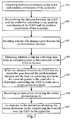
- Fig. 1 is a flowchart showing a method for controlling an UAV according to an exemplary embodiment. The method is performed by an UAV, and may comprise the following steps as shown in Fig. 1 .
- Step 101 it is determined whether a distance between an Unmanned Aerial Vehicle (UAV) and a controller of the UAV goes beyond (i.e. exceeds) human's viewing distance.
- UAV Unmanned Aerial Vehicle
- the controller may be a remote or a mobile terminal.
- the human's viewing distance is a predetermined distance.
- the human's viewing distance may be a default value set by the manufacture when the UAV is delivered.
- the human's viewing distance may also be a user-defined value set by the user using the remote or the mobile terminal during operation.
- Step 102 it is detected whether a link for collecting data from an external system of the UAV is normal.
- the external system is configured to detect a flying environment of the UAV, and the link for collecting data is configured to send data detected by the external system about the flying environment to the controller, so that the user can check the flying environment of the UAV by using the controller.
- the link for collecting data is normal if said link meets at least one predefined criteria: the data from the link for collecting data is receivable; or the handshaking information is acknowledged in time.
- Step 103 when the distance between the UAV and the controller goes beyond the human's viewing distance and the link for collecting data from the external system to the controller is abnormal, the UAV is controlled to enter into a return protection mode.
- the controlling the UAV to enter into a return protection mode comprises any one of: controlling the UAV to fly back to a position where the controller is located; and controlling the UAV to fly back to a predetermined position.
- the predetermined position may be a set of predetermined position coordinates.
- the UAV in such case when the distance between the UAV and the controller goes beyond the human's viewing distance and the link for collecting data from the external system to the controller is abnormal, as it is hard for the users to determine the flying environment of their UAV, the UAV is controlled to enter into a return protection mode. This way the UAV can be protected, thus reducing the possibility of a collision of the UAV with objects surrounding it and improving the UAV safety.
- Fig. 2 is a flow chart showing another method for controlling an UAV according to an exemplary embodiment.
- the method is performed in an UAV, and in this embodiment, the external system may be a camera, an infrared sensor system or a depth-of-field camera (DOF Camera).
- the method may comprise the following steps.
- Step 201 position coordinates of the UAV and position coordinates of the controller are acquired.
- the controller may be a remote or a mobile terminal.
- the step 201 may comprise:
- the positioning systems may comprise at least one of a GPS, a Base Station Positioning System and a Wireless Fidelity Positioning System.
- the position coordinates of the controller may be transmitted through a control channel between the controller and the UAV, which is also the channel for transmitting a control instruction from the controller to the UAV.
- Step 202 the distance between the UAV and the controller is determined according to the position coordinates of the UAV and the position coordinates of the controller.
- the distance between the UAV and the controller may be calculated based on the formula of the distance between two points.
- Step 203 it is decided whether the distance between the UAV and the controller goes beyond the human's viewing distance.
- the human's viewing distance may be a default value set by the manufacture when the UAV is delivered.
- the human's viewing distance may also be a user-defined value set by the user using the remote or the mobile terminal during operation.
- Steps 201-203 it can be decided whether the distance between the UAV and the controller goes beyond the human's viewing distance.
- Step 204 it is detected whether a link for collecting data from an external system of the UAV is normal.
- the external system is configured on the UAV to detect a flying environment of the UAV, and the link for collecting data is configured to send data detected by the external system about the flying environment to the controller, so that the user can check the flying environment of the UAV by using the controller.
- the link for collecting data is independent from the link through which the controller sends the control instruction between the controller and the UAV, so even if the link for collecting data is abnormal, the transmission of the position coordinates of the controller may not be affected.
- the external system may comprise at least one of a camera, an infrared sensor system and a depth-of-field camera.
- the camera will capture images around the UAV.
- the captured images of the camera that is the data about the flying environment
- the mobile terminal of the user via said link, allowing the user to determine accurately the flying environment of the UAV.
- the infrared sensor system or the depth-of-field camera may sense the relative position information between the UAV and the objects surrounding it (that is the data about the flying environment).
- the infrared sensor system or the depth-of-field camera may transmit the sensed relative position information to the mobile terminal of the user.
- Step 204 may comprise:
- Step 205 when the distance between the UAV and the controller goes beyond the human's viewing distance and the link for collecting data from the external system to the controller is abnormal, the UAV is controlled to enter into a return protection mode.
- the controlling the UAV to enter into a return protection mode comprises any one of: controlling the UAV to fly back to a position where the controller is located and controlling the UAV to fly back to a predetermined position.
- Controlling the UAV to fly normally means giving control over the UAV to the controller, which may comprise:
- the method of this embodiment may further comprise the following steps:
- Steps 201-203 and Step 204 are not limited. Steps 201-203 and Step 204 may be carried out at the same time; or Steps 201-203 may be carried out firstly, and when the distance between the UAV and the controller of the UAV goes beyond the human's viewing distance, step 204 is then carried out; or Step 204 may be carried out firstly, and when the link for collecting data from the external system of the UAV is abnormal, steps 201-203 are then carried out.
- the method may further comprise:
- the users can send instructions of forbidding flying beyond the viewing distance to their UAV by operating their controller in some scenarios.
- One scenario is that during the flight of the UAV, when the UAV flies back within the range of the viewing distance, i.e., when the users find their UAV in sight, due to the link for collecting data being abnormal, the users cannot know the flying environment of their UAV.
- Another scenario is when the UAV just takes off (operated by new users).
- the method may further comprise:
- the controlling the UAV to fly within the viewing distance may further comprise:
- the UAV is controlled to enter into a return protection mode. This way the UAV can be protected, thus reducing the possibility of a collision of the UAV whith objects surrounding it and improving the UAV safety.
- Fig. 3 is a structural block diagram of a device for controlling an UAV according to an exemplary embodiment. As shown in Fig. 3 , the device may comprise a determination module 301, a detection module 302 and a controlling module 303.
- the determination module 301 is configured to determine whether a distance between an Unmanned Aerial Vehicle (UAV) and a controller of the UAV goes beyond human's viewing distance.
- UAV Unmanned Aerial Vehicle
- the detection module 302 is configured to detect whether a link for collecting data from an external system of the UAV to the controller is normal.
- the controlling module 303 is configured to, when the distance between the UAV and the controller goes beyond the human's viewing distance and the link for collecting data of the external system to the controller is abnormal, control the UAV to enter into a return protection mode.
- the controller may be a remote or a mobile terminal.
- the human's viewing distance may be a default value set by the manufacture when the UAV is delivered
- the human's viewing distance may also be a user-defined value set by the user using the remote or the mobile terminal during operation.
- the external system is configured to detect a flying environment of the UAV, and the link for collecting data is configured to send data detected by the external system about the flying environment to the controller, so that the user can check the flying environment of the UAV by using the controller.
- the UAV in such case when the distance between the UAV and the controller goes beyond the human's viewing distance and the link for collecting data from the external system to the controller is abnormal, as it is hard for the users to determine the flying environment of their UAV, the UAV is controlled to enter into a return protection mode. This way the UAV can be protected, thus reducing the possibility of a collision of the UAV with objects surrounding it and improving the UAV safety.
- Fig. 4 is a structural block diagram of a device for controlling an UAV according to an exemplary embodiment. As shown in Fig. 4 , the device may comprise a determination module 401, a detection module 402 and a controlling module 403.
- the determination module 401 is configured to determine whether a distance between the Unmanned Aerial Vehicle (UAV) and a controller of the UAV goes beyond human's viewing distance.
- UAV Unmanned Aerial Vehicle
- the detection module 402 is configured to detect whether a link for collecting data from an external system of the UAV to the controller is normal.
- the controlling module 403 is configured to, when the distance between the UAV and the controller goes beyond the human's viewing distance and the link for collecting data from the external system to the controller is abnormal, control the UAV to enter into a return protection mode.
- the controller may be a remote or a mobile terminal.
- the human's viewing distance may be a default value set by the manufacture when the UAV is delivered.
- the human's viewing distance may also be a user-defined value set by the user using the remote or the mobile terminal during operation.
- the external system is configured on the UAV to detect a flying environment of the UAV, and the link for collecting data is configured to send data detected by the external system about the flying environment to the controller, so that the user can check the flying environment of the UAV by using the controller.
- the link for collecting data is independent from the link through which the controller sends the control instruction between the controller and the UAV, so even if the link for collecting data is abnormal, the transmission of the position coordinates of the controller may not be affected.
- the external system may comprise at least one of a camera, an infrared sensor system and a depth-of-field camera.
- the camera will capture images around the UAV.
- the captured images of the camera that is the data about the flying environment
- the link for collecting data is transmitted to the mobile terminal of the user via the link for collecting data, allowing the user to determine accurately the flying environment of the UAV.
- the infrared sensor system or the depth-of-field camera may sense the relative position information between the UAV and the objects surrounding it (that is the data about the flying environment).
- the infrared sensor system or the depth-of-field camera may transmit the sensed relative position information to the mobile terminal of the user.
- controlling module 403 is configured to any one of control the UAV to fly back to a position where the controller is located; and control the UAV to fly back to a predetermined position.
- the determination module 401 comprises an acquisition sub-module 4011, a determination sub-module 4012, and a deciding sub-module 4013.
- the acquisition sub-module 4011 is configured to acquire position coordinates of the UAV and position coordinates of the controller.
- the determination sub-module 4012 is configured to determine the distance between the UAV and the controller according to the position coordinates of the UAV and the position coordinates of the controller acquired by the acquisition sub-module 4011.
- the deciding sub-module 4013 is configured to decide whether the distance determined by the determination sub-module goes beyond the human's viewing distance.
- the acquisition sub-module 4011 is configured to acquire the position coordinates of the UAV using a positioning system of the UAV; receive the position coordinates of the controller sent from the controller, the position coordinates of the controller being acquired by the controller using a positioning system of the controller.
- the positioning system of the UAV and the positioning system of the controller may comprise at least one of a GPS, a Base Station Positioning System and a Wireless Fidelity Positioning System.
- the position coordinates of the controller may be transmitted through a control channel between the controller and the UAV, which is also the channel for transmitting a control instruction sent from the controller to the UAV.
- the device may further comprise: a receiving module 404 configured to receive an instruction of exiting the return protection mode.
- the controlling module 403 is further configured to, in response to the instruction of exiting the return protection mode received by the receiving module 404, transfer control over the UAV to the controller.
- controlling module 403 is further configured to, when the distance between the UAV and the controller goes beyond the human's viewing distance while the link for collecting data from the external system to the controller is normal, or when the distance between the UAV and the controller is within the human's viewing distance (no matter whether the link for collecting data from the external system to the controller is normal or not), control the UAV to fly normally, i.e., give the control over the UAV to the controller, and control the UAV to fly according to the flying instruction of the controller.
- the receiving module 404 is further configured to receive a flying instruction sent from the controller, which may be one or combination of turning left, turning right, diving, speeding up, speeding down and so on.
- controlling module 403 is further configured to control the UAV to fly according to the received flying instruction.
- controlling module 403 is further configured to, when the distance between the UAV and the controller is within the range of the viewing distance while the link for collecting data from the external system to the controller is abnormal, control the UAV to fly within the range of the human's viewing distance. At this time, controlling the UAV to fly within the range of the human's viewing distance may further improve the flight safety of the UAV.
- the users can send instructions of forbidding flying beyond the viewing distance to their UAV by operating their controller in some scenarios.
- One scenario is that during the flight of the UAV, when the UAV flies back within the range of the viewing distance, i.e., when the users find their UAV in sight, due to the link for collecting data being abnormal, the users cannot know the flying environment of their UAV.
- Another scenario is when the UAV just takes off (operated by new users).
- the receiving module is further configured to receive an instruction of forbidding flying beyond the viewing distance; and the controlling module is further configured to, in response to the instruction of forbidding flying beyond the viewing distance, control the UAV to fly within the viewing distance.
- controlling module 403 is further configured to detect the distance between the UAV and the controller, and when the distance between the UAV and the controller reaches the viewing distance, control the UAV to fly toward the controller.
- the UAV in such case when the distance between the UAV and the controller goes beyond the human's viewing distance and the link for collecting data from the external system to the controller is abnormal, as it is hard for the users to determine the flying environment of their UAV, the UAV is controlled to enter into a return protection mode. This way the UAV can be protected, thus reducing the possibility of a collision of the UAV with objects surrounding it and improving the UAV safety.
- modules can each be implemented by hardware, or software, or a combination of hardware and software.
- the modules When implemented in hardware, the modules may be implemented as one or more hardware modules, such as one or more application specific integrated circuits.
- the modules When implemented in software, the modules may be implemented as one or more computer programs that are executed on one or more processors.
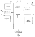
- Fig. 5 is a structural block diagram of a device 500 for controlling an UAV according to an exemplary embodiment.
- the device 500 may be an UAV or the like.
- the device 500 may comprise one or more of the following components: a processing component 502, a memory 504, a power supply component 506, a multimedia component 508, an input/output (I/O) interface 512, a sensor component 514, and a communication component 516.
- the processing component 502 typically controls overall operations of the device 500, such as the operations associated with data communications, camera operations, and recording operations.
- the processing component 502 may comprise one or more processors 520 to execute instructions to perform all or part of the steps in the above described methods.
- the processing component 502 may comprise one or more modules which facilitate the interaction between the processing component 502 and other components.
- the processing component 502 may comprise a multimedia module to facilitate the interaction between the multimedia component 508 and the processing component 502.
- the memory 504 is configured to store various types of data to support the operation of the device 500. Examples of such data comprise instructions for any applications or methods operated on the device 500.
- the memory 504 may be implemented using any type of volatile or non-volatile memory devices, or a combination thereof, such as a static random access memory (SRAM), an electrically erasable programmable read-only memory (EEPROM), an erasable programmable read-only memory (EPROM), a programmable read-only memory (PROM), a read-only memory (ROM), a magnetic memory, a flash memory, a magnetic or optical disk.
- SRAM static random access memory
- EEPROM electrically erasable programmable read-only memory
- EPROM erasable programmable read-only memory
- PROM programmable read-only memory
- ROM read-only memory
- magnetic memory a magnetic memory
- flash memory a flash memory
- magnetic or optical disk a magnetic or optical disk.
- the power supply component 506 provides power to various components of the device 500.
- the power supply component 506 may comprise a power management system, one or more power sources, and any other components associated with the generation, management, and distribution of power in the device 500.
- the multimedia component 508 comprises at least one camera.
- the camera may receive external multimedia data.
- Each camera may be a fixed optical lens system or have focal length and optical zoom capability.
- the I/O interface 512 provides an interface between the processing component 502 and peripheral interface modules, such as a keyboard, a click wheel, buttons, and the like.
- the sensor component 514 comprises one or more sensors to provide status assessments of various aspects of the device 500.
- the sensor component 514 may detect an environment in which the device 500 is located.
- the sensor component 514 may comprise an infrared sensor configured to detect distances from the device 500 to objects surrounding the object 500.
- the sensor component 514 may also comprise a light sensor, such as a CMOS or CCD image sensor, for use in imaging applications.
- the sensor component 514 may also comprise an accelerometer sensor, a gyroscope sensor, a magnetic sensor, a pressure sensor, or a temperature sensor.
- the communication component 516 is configured to facilitate communication, wired or wirelessly, between the device 500 and other devices.
- the device 500 can access a wireless network based on a communication standard, such as WiFi, 2G, or 3G, or a combination thereof.
- the communication component 516 receives a broadcast signal or broadcast associated information from an external broadcast management system via a broadcast channel.
- the communication component 516 further comprises a near field communication (NFC) module to facilitate short-range communications.
- the NFC module may be implemented based on a radio frequency identification (RFID) technology, an infrared data association (IrDA) technology, an ultra-wideband (UWB) technology, a Bluetooth (BT) technology, and other technologies.
- RFID radio frequency identification
- IrDA infrared data association
- UWB ultra-wideband
- BT Bluetooth
- the device 500 may be implemented with one or more application specific integrated circuits (ASICs), digital signal processors (DSPs), digital signal processing devices (DSPDs), programmable logic devices (PLDs), field programmable gate arrays (FPGAs), controllers, micro-controllers, microprocessors, or other electronic components, for performing the above described methods.
- ASICs application specific integrated circuits
- DSPs digital signal processors
- DSPDs digital signal processing devices
- PLDs programmable logic devices
- FPGAs field programmable gate arrays
- controllers micro-controllers, microprocessors, or other electronic components, for performing the above described methods.
- non-transitory computer-readable storage medium comprising instructions, such as comprised in the memory 504, executable by the processor 520 in the device 500, for performing the above-described methods.
- the non-transitory computer-readable storage medium may be a ROM, a RAM, a CD-ROM, a magnetic tape, a floppy disc, an optical data storage device, and the like.
- Non-transitory computer readable storage medium storing instructions, executable by a processor of an Unmanned Aerial Vehicle (UAV), enabling the UAV to perform a method for controlling the UAV, comprising:
- the determining whether a distance between an Unmanned Aerial Vehicle (UAV) and the controller of the UAV goes beyond human's viewing distance comprises:
- the acquiring the position coordinates of the UAV and the position coordinates of the controller comprises:
- the human's viewing distance is any one of a default value and a user-defined value.
- the external system comprises at least one of a camera, an infrared sensor system and a depth-of-field camera.
- controlling the UAV to enter into a return protection mode comprises any one of:
- the method further comprises:
Landscapes
- Engineering & Computer Science (AREA)
- Physics & Mathematics (AREA)
- General Physics & Mathematics (AREA)
- Aviation & Aerospace Engineering (AREA)
- Radar, Positioning & Navigation (AREA)
- Remote Sensing (AREA)
- Automation & Control Theory (AREA)
- Computer Networks & Wireless Communication (AREA)
- Control Of Position, Course, Altitude, Or Attitude Of Moving Bodies (AREA)
- Traffic Control Systems (AREA)
- Selective Calling Equipment (AREA)
Abstract
Description
- The present invention generally relates to Unmanned Aerial Vehicles (UAV) or drones in the security field, and more particularly to a method and a device for controlling an UAV.
- The market of consumer-oriented UAVs is getting more and more attention, and many traditional enterprises that manufacture consumer-oriented UAVs and information technology companies are investing economical and human resources in area of developing UAVs. Large numbers of ordinary users without relevant expertise begin operating UAVs to fly for purpose of entertainment and try to let them fly beyond their viewing distance. When the distance between an UAV and a controller of the UAV goes beyond human's viewing distance, it is hard for the users to accurately determine the flying environment of their UAV, which therefore causes a potential risk in the flight of the UAV.
- In order to solve the problem of the related technologies, the present invention provides a method and a device for controlling an Unmanned Aerial Vehicle.
- According to a first aspect of embodiments, the invention relates to a method for controlling an Unmanned Aerial Vehicle, comprising:
- determining whether a distance between the Unmanned Aerial Vehicle (UAV) and the controller UAV goes beyond a predetermined distance;
- detecting whether a link for collecting data from an external system of the UAV to the controller is normal, the external system being configured to detect a flying environment of the UAV; and
- when the distance between the UAV and the controller goes beyond the predetermined distance and the link for collecting data from the external system to the controller is abnormal, controlling the UAV to enter into a return protection mode.
- In a particular embodiment, said determining whether a distance between an Unmanned Aerial Vehicle (UAV) and a controller of the UAV goes beyond the predetermined distance comprises:
- acquiring position coordinates of the UAV and position coordinates of the controller;
- determining the distance between the UAV and the controller according to the position coordinates of the UAV and the position coordinates of the controller; and
- deciding whether the distance between the UAV and the controller goes beyond the predetermined distance.
- In a particular embodiment, said acquiring the position coordinates of the UAV and the position coordinates of the controller comprises:
- acquiring the position coordinates of the UAV using a positioning system of the UAV; and
- receiving the position coordinates of the controller sent from the controller, the position coordinates of the controller being acquired by the controller using a positioning system of the controller,
- wherein the positioning system of the UAV and the positioning system of the controller comprise at least one of a GPS, a Base Station Positioning System and a Wireless Fidelity Positioning System.
- In a particular embodiment, the predetermined distance is any one of a default value and a user-defined value.
- In a particular embodiment, the external system comprises at least one of a camera, an infrared sensor system and a depth-of-field camera.
- In a particular embodiment, said controlling the UAV to enter into a return protection mode comprises any one of:
- controlling the UAV to fly back to a position where the controller is located; and
- controlling the UAV to fly back to a predetermined position.
- According to another implementation of the present invention, the method further comprises:
- receiving an instruction of exiting the return protection mode; and
- in response to the instruction of exiting the return protection mode, transferring control over the UAV to the controller.
- According to a second aspect of the embodiments, the invention relates to a device for controlling an Unmanned Aerial Vehicle, comprising:
- a determination module configured to determine whether a distance between the Unmanned Aerial Vehicle (UAV) and a controller of the UAV goes beyond a predetermined distance;
- a detection module configured to detect whether a link for collecting data from an external system of the UAV to the controller is normal, the external system being configured to detect a flying environment of the UAV; and
- a controlling module configured to, when the distance between the UAV and the controller goes beyond the predetermined distance and the link for collecting data from the external system to the controller is abnormal, control the UAV to enter into a return protection mode.
- According to an implementation of the present invention, said determination module comprises:
- an acquisition sub-module configured to acquire position coordinates of the UAV and position coordinates of the controller;
- a determination sub-module configured to determine the distance between the UAV and the controller according to the position coordinates of the UAV and the position coordinates of the controller acquired by the acquisition sub-module; and
- a deciding sub-module configured to decide whether the distance determined by the determination sub-module goes beyond the predetermined distance.
- Further, said acquisition sub-module is configured to acquire the position coordinates of the UAV using a positioning system of the UAV; receive the position coordinates of the controller sent from the controller, the position coordinates of the controller being acquired by the controller using a positioning system of the controller, wherein the positioning system of the UAV and the positioning system of the controller comprise at least one of a GPS, a Base Station Positioning System and a Wireless Fidelity Positioning System.
- In a particular embodiment, the predetermined distance is any one of a default value and a user-defined value.
- In a particular embodiment, the external system comprises at least one of a camera, an infrared sensor system and a depth-of-field camera.
- In a particular embodiment, said controlling module is configured to any one of control the UAV to fly back to a position where the controller is located; and control the UAV to fly back to a predetermined position.
- According to another implementation of the present invention, the device further comprises:
- a receiving module configured to receive an instruction of exiting the return protection mode, wherein
- the controlling module is configured to, in response to the instruction of exiting the return protection mode, transfer control over the UAV to the controller.
- According to a third aspect of the embodiments, the invention relates to a device for controlling an Unmanned Aerial Vehicle, comprising:
- a processor; and
- a memory for storing instructions executable by the processor;
- wherein the processor is configured to:
- determine whether a distance between an Unmanned Aerial Vehicle (UAV) and a controller of the UAV goes beyond a predetermined distance;
- detect whether a link for collecting data from an external system of the UAV to the controller is normal, the external system being configured to detect a flying environment of the UAV; and
- when the distance between the UAV and the controller goes beyond the predetermined distance and the link for collecting data from the external system to the controller is abnormal, control the UAV to enter into a return protection mode.
- In an exemplary embodiment, the steps of the above method for controlling an unmanned aerial vehicle are determined by computer program instructions.
- Consequently, according to a fourth aspect, the invention also relates to a computer program for executing the steps of a method for controlling an unmanned aerial vehicle as defined above when this program is executed by a computer.
- This program can use any programming language and take the form of source code, object code or a code intermediate between source code and object code, such as a partially compiled form, or any other desirable form.
- According to a fifth aspect, the invention also relates to a computer-readable information medium containing instructions of a computer program as defined above.
- The information medium can be any entity or device capable of storing the program. For example, the information medium can comprise storage means such as a ROM, for example a CD ROM or a microelectronic circuit ROM, or magnetic storage means, for example a diskette (floppy disk) or a hard disk. Alternatively, the information medium can be an integrated circuit in which the program is incorporated, the circuit being adapted to execute the method in question or to be used in its execution.
- The technical solutions provided by the embodiments of the present invention may have the following beneficial effects:
- When the distance between the UAV and the controller goes beyond the predetermined distance and the link for collecting data from the external system to the controller is abnormal, it is hard for the users to determine the flying environment of their UAV. In such case, controlling the UAV to enter into a return protection mode can protect the UAV, leading to a reduction of the possibility that the UAV collides with objects surrounding it and an improvement of the UAV safety.
- It is to be understood that both the foregoing general description and the following detailed description are exemplary and explanatory only and are not restrictive of the invention.
- The accompanying drawings, which are incorporated in and constitute a part of this specification, illustrate embodiments consistent with the invention and, together with the description, serve to explain the principles of the invention.
-
Fig. 1 is a flow chart showing a method for controlling an UAV according to an exemplary embodiment. -
Fig. 2 is a flow chart showing another method for controlling an UAV according to an exemplary embodiment. -
Fig. 3 is a structural block diagram of a device for controlling an UAV according to an exemplary embodiment. -
Fig. 4 is a structural block diagram of another device for controlling an UAV according to an exemplary embodiment. -
Fig. 5 is a structural block diagram of another device for controlling an UAV according to an exemplary embodiment. - Reference will now be made in detail to exemplary embodiments, examples of which are illustrated in the accompanying drawings. The following description refers to the accompanying drawings in which the same numbers in different drawings represent the same or similar elements unless otherwise represented. The implementations set forth in the following description of exemplary embodiments do not represent all implementations consistent with the invention. Instead, they are merely examples of devices and methods consistent with aspects related to the invention as recited in the appended claims.
-
Fig. 1 is a flowchart showing a method for controlling an UAV according to an exemplary embodiment. The method is performed by an UAV, and may comprise the following steps as shown inFig. 1 . - In
Step 101, it is determined whether a distance between an Unmanned Aerial Vehicle (UAV) and a controller of the UAV goes beyond (i.e. exceeds) human's viewing distance. - The controller may be a remote or a mobile terminal. In a particular example, the human's viewing distance is a predetermined distance. The human's viewing distance may be a default value set by the manufacture when the UAV is delivered. The human's viewing distance may also be a user-defined value set by the user using the remote or the mobile terminal during operation.
- In
Step 102, it is detected whether a link for collecting data from an external system of the UAV is normal. - The external system is configured to detect a flying environment of the UAV, and the link for collecting data is configured to send data detected by the external system about the flying environment to the controller, so that the user can check the flying environment of the UAV by using the controller. In a particular example, in
step 102, the link for collecting data is normal if said link meets at least one predefined criteria: the data from the link for collecting data is receivable; or the handshaking information is acknowledged in time. InStep 103, when the distance between the UAV and the controller goes beyond the human's viewing distance and the link for collecting data from the external system to the controller is abnormal, the UAV is controlled to enter into a return protection mode. - The controlling the UAV to enter into a return protection mode comprises any one of: controlling the UAV to fly back to a position where the controller is located; and controlling the UAV to fly back to a predetermined position.
- In a particular example, the predetermined position may be a set of predetermined position coordinates.
- In this embodiment, in such case when the distance between the UAV and the controller goes beyond the human's viewing distance and the link for collecting data from the external system to the controller is abnormal, as it is hard for the users to determine the flying environment of their UAV, the UAV is controlled to enter into a return protection mode. This way the UAV can be protected, thus reducing the possibility of a collision of the UAV with objects surrounding it and improving the UAV safety.
-
Fig. 2 is a flow chart showing another method for controlling an UAV according to an exemplary embodiment. The method is performed in an UAV, and in this embodiment, the external system may be a camera, an infrared sensor system or a depth-of-field camera (DOF Camera). As shown inFig. 2 , the method may comprise the following steps. - In
Step 201, position coordinates of the UAV and position coordinates of the controller are acquired. - The controller may be a remote or a mobile terminal.
- The
step 201 may comprise: - acquiring the position coordinates of the UAV using a positioning system of the UAV;
- receiving the position coordinates of the controller sent from the controller, the position coordinates of the controller being acquired by the controller using a positioning system of the controller.
- The positioning systems may comprise at least one of a GPS, a Base Station Positioning System and a Wireless Fidelity Positioning System.
- It should be noted that in this embodiment the position coordinates of the controller may be transmitted through a control channel between the controller and the UAV, which is also the channel for transmitting a control instruction from the controller to the UAV.
- In
Step 202, the distance between the UAV and the controller is determined according to the position coordinates of the UAV and the position coordinates of the controller. - For example, if the position coordinates of the UAV is (a1, b1), and the position coordinates of the controller is (a2, b2), the distance between the UAV and the controller may be calculated based on the formula of the distance between two points.
- In
Step 203, it is decided whether the distance between the UAV and the controller goes beyond the human's viewing distance. - The human's viewing distance may be a default value set by the manufacture when the UAV is delivered. The human's viewing distance may also be a user-defined value set by the user using the remote or the mobile terminal during operation.
- By carrying out the Steps 201-203, it can be decided whether the distance between the UAV and the controller goes beyond the human's viewing distance.
- In
Step 204, it is detected whether a link for collecting data from an external system of the UAV is normal. - The external system is configured on the UAV to detect a flying environment of the UAV, and the link for collecting data is configured to send data detected by the external system about the flying environment to the controller, so that the user can check the flying environment of the UAV by using the controller. Preferably, the link for collecting data is independent from the link through which the controller sends the control instruction between the controller and the UAV, so even if the link for collecting data is abnormal, the transmission of the position coordinates of the controller may not be affected.
- Further, the external system may comprise at least one of a camera, an infrared sensor system and a depth-of-field camera.
- If the external system is a camera, the camera will capture images around the UAV. When the link for collecting data is normal, the captured images of the camera (that is the data about the flying environment) are transmitted to the mobile terminal of the user via said link, allowing the user to determine accurately the flying environment of the UAV.
- If the external system is an infrared sensor system or a depth-of-field camera, the infrared sensor system or the depth-of-field camera may sense the relative position information between the UAV and the objects surrounding it (that is the data about the flying environment). When the link for collecting data is normal, the infrared sensor system or the depth-of-field camera may transmit the sensed relative position information to the mobile terminal of the user.
- According to an implementation of this embodiment, the
Step 204 may comprise: - periodically sending handshake information such as an acknowledgment to the controller via the link for collecting data; and
- if response information sent from the controller is not received within a set length of time (i.e. time duration), then deciding that the link for collecting data is abnormal.
- In
Step 205, when the distance between the UAV and the controller goes beyond the human's viewing distance and the link for collecting data from the external system to the controller is abnormal, the UAV is controlled to enter into a return protection mode. - The controlling the UAV to enter into a return protection mode comprises any one of: controlling the UAV to fly back to a position where the controller is located and controlling the UAV to fly back to a predetermined position.
- The method of this embodiment may further comprise:
- when the distance between the UAV and the controller goes beyond the human's viewing distance while the link for collecting data from the external system to the controller is normal, or when the distance between the UAV and the controller is within the human's viewing distance (no matter whether the link for collecting data from the external system to the controller is normal or not), the UAV is controlled to fly normally.
- Controlling the UAV to fly normally means giving control over the UAV to the controller, which may comprise:
- receiving a flying instruction sent from the controller, which may be one or combination of turning left, turning right, diving, speeding up, speeding down and so on.
- controlling the UAV to fly according to the received flying instruction.
- When the UAV flies back within the range of the viewing distance, i.e., when the users find that they can see their UAV, they can exit the return protection mode manually using their controller, so as to transfer the control over the UAV to the controller, which then makes the UAV enter into a normal flying state. Therefore, the method of this embodiment may further comprise the following steps:
- In
Step 206, an instruction of exiting the return protection mode is received. - In
Step 207, in response to the instruction of exiting the return protection mode, the control over the UAV is transferred to the controller (i.e. normal flying state). - It should be noted that in particular implementations, the time sequence of Steps 201-203 and
Step 204 is not limited. Steps 201-203 andStep 204 may be carried out at the same time; or Steps 201-203 may be carried out firstly, and when the distance between the UAV and the controller of the UAV goes beyond the human's viewing distance,step 204 is then carried out; orStep 204 may be carried out firstly, and when the link for collecting data from the external system of the UAV is abnormal, steps 201-203 are then carried out. - In addition, the method may further comprise:
- when the distance between the UAV and the controller is within the range of the viewing distance while the link for collecting data from the external system is abnormal, the UAV is controlled to fly within the range of the human's viewing distance. At this time, controlling the UAV to fly within the range of the human's viewing distance may further improve the flight safety of the UAV.
- In particular implementations, the users can send instructions of forbidding flying beyond the viewing distance to their UAV by operating their controller in some scenarios. One scenario is that during the flight of the UAV, when the UAV flies back within the range of the viewing distance, i.e., when the users find their UAV in sight, due to the link for collecting data being abnormal, the users cannot know the flying environment of their UAV. Another scenario is when the UAV just takes off (operated by new users).
- In such case, the method may further comprise:
- receiving an instruction of forbidding flying beyond the viewing distance;
- in response to the instruction of forbidding flying beyond the viewing distance, controlling the UAV to fly within the viewing distance.
- The controlling the UAV to fly within the viewing distance may further comprise:
- detecting the distance between the UAV and the controller; and
- when the distance between the UAV and the controller reaches the viewing distance, controlling the UAV to fly toward the controller.
- In such case when the distance between the UAV and the controller goes beyond the human's viewing distance and the link for collecting data from the external system to the controller is abnormal, as it is hard for the users to determine the flying environment of their UAV, the UAV is controlled to enter into a return protection mode. This way the UAV can be protected, thus reducing the possibility of a collision of the UAV whith objects surrounding it and improving the UAV safety.
-
Fig. 3 is a structural block diagram of a device for controlling an UAV according to an exemplary embodiment. As shown inFig. 3 , the device may comprise adetermination module 301, adetection module 302 and a controllingmodule 303. - The
determination module 301 is configured to determine whether a distance between an Unmanned Aerial Vehicle (UAV) and a controller of the UAV goes beyond human's viewing distance. - The
detection module 302 is configured to detect whether a link for collecting data from an external system of the UAV to the controller is normal. - The controlling
module 303 is configured to, when the distance between the UAV and the controller goes beyond the human's viewing distance and the link for collecting data of the external system to the controller is abnormal, control the UAV to enter into a return protection mode. - The controller may be a remote or a mobile terminal. The human's viewing distance may be a default value set by the manufacture when the UAV is delivered The human's viewing distance may also be a user-defined value set by the user using the remote or the mobile terminal during operation.
- The external system is configured to detect a flying environment of the UAV, and the link for collecting data is configured to send data detected by the external system about the flying environment to the controller, so that the user can check the flying environment of the UAV by using the controller.
- In this embodiment, in such case when the distance between the UAV and the controller goes beyond the human's viewing distance and the link for collecting data from the external system to the controller is abnormal, as it is hard for the users to determine the flying environment of their UAV, the UAV is controlled to enter into a return protection mode. This way the UAV can be protected, thus reducing the possibility of a collision of the UAV with objects surrounding it and improving the UAV safety.
-
Fig. 4 is a structural block diagram of a device for controlling an UAV according to an exemplary embodiment. As shown inFig. 4 , the device may comprise adetermination module 401, adetection module 402 and a controllingmodule 403. - The
determination module 401 is configured to determine whether a distance between the Unmanned Aerial Vehicle (UAV) and a controller of the UAV goes beyond human's viewing distance. - The
detection module 402 is configured to detect whether a link for collecting data from an external system of the UAV to the controller is normal. - The controlling
module 403 is configured to, when the distance between the UAV and the controller goes beyond the human's viewing distance and the link for collecting data from the external system to the controller is abnormal, control the UAV to enter into a return protection mode. - The controller may be a remote or a mobile terminal. The human's viewing distance may be a default value set by the manufacture when the UAV is delivered. The human's viewing distance may also be a user-defined value set by the user using the remote or the mobile terminal during operation.
- The external system is configured on the UAV to detect a flying environment of the UAV, and the link for collecting data is configured to send data detected by the external system about the flying environment to the controller, so that the user can check the flying environment of the UAV by using the controller. Preferably, the link for collecting data is independent from the link through which the controller sends the control instruction between the controller and the UAV, so even if the link for collecting data is abnormal, the transmission of the position coordinates of the controller may not be affected.
- Further, the external system may comprise at least one of a camera, an infrared sensor system and a depth-of-field camera.
- If the external system is a camera, the camera will capture images around the UAV. When the link for collecting data is normal, the captured images of the camera (that is the data about the flying environment) are transmitted to the mobile terminal of the user via the link for collecting data, allowing the user to determine accurately the flying environment of the UAV.
- If the external system is an infrared sensor system or a depth-of-field camera, the infrared sensor system or the depth-of-field camera may sense the relative position information between the UAV and the objects surrounding it (that is the data about the flying environment). When the link for collecting data is normal, the infrared sensor system or the depth-of-field camera may transmit the sensed relative position information to the mobile terminal of the user.
- Further, the controlling
module 403 is configured to any one of control the UAV to fly back to a position where the controller is located; and control the UAV to fly back to a predetermined position. - Further, the
determination module 401 comprises anacquisition sub-module 4011, adetermination sub-module 4012, and a deciding sub-module 4013. - The acquisition sub-module 4011 is configured to acquire position coordinates of the UAV and position coordinates of the controller.
- The determination sub-module 4012 is configured to determine the distance between the UAV and the controller according to the position coordinates of the UAV and the position coordinates of the controller acquired by the
acquisition sub-module 4011. - The deciding sub-module 4013 is configured to decide whether the distance determined by the determination sub-module goes beyond the human's viewing distance.
- Further, the acquisition sub-module 4011 is configured to acquire the position coordinates of the UAV using a positioning system of the UAV; receive the position coordinates of the controller sent from the controller, the position coordinates of the controller being acquired by the controller using a positioning system of the controller.
- The positioning system of the UAV and the positioning system of the controller may comprise at least one of a GPS, a Base Station Positioning System and a Wireless Fidelity Positioning System.
- It should be noted that in this embodiment the position coordinates of the controller may be transmitted through a control channel between the controller and the UAV, which is also the channel for transmitting a control instruction sent from the controller to the UAV.
- According to an implementation of the embodiments of the present invention, the device may further comprise: a receiving
module 404 configured to receive an instruction of exiting the return protection mode. The controllingmodule 403 is further configured to, in response to the instruction of exiting the return protection mode received by the receivingmodule 404, transfer control over the UAV to the controller. - It should be noted that in this embodiment, the controlling
module 403 is further configured to, when the distance between the UAV and the controller goes beyond the human's viewing distance while the link for collecting data from the external system to the controller is normal, or when the distance between the UAV and the controller is within the human's viewing distance (no matter whether the link for collecting data from the external system to the controller is normal or not), control the UAV to fly normally, i.e., give the control over the UAV to the controller, and control the UAV to fly according to the flying instruction of the controller. - Further, the receiving
module 404 is further configured to receive a flying instruction sent from the controller, which may be one or combination of turning left, turning right, diving, speeding up, speeding down and so on. - In addition, the controlling
module 403 is further configured to control the UAV to fly according to the received flying instruction. - Furthermore, the controlling
module 403 is further configured to, when the distance between the UAV and the controller is within the range of the viewing distance while the link for collecting data from the external system to the controller is abnormal, control the UAV to fly within the range of the human's viewing distance. At this time, controlling the UAV to fly within the range of the human's viewing distance may further improve the flight safety of the UAV. - In particular implementations, the users can send instructions of forbidding flying beyond the viewing distance to their UAV by operating their controller in some scenarios. One scenario is that during the flight of the UAV, when the UAV flies back within the range of the viewing distance, i.e., when the users find their UAV in sight, due to the link for collecting data being abnormal, the users cannot know the flying environment of their UAV. Another scenario is when the UAV just takes off (operated by new users). The receiving module is further configured to receive an instruction of forbidding flying beyond the viewing distance; and the controlling module is further configured to, in response to the instruction of forbidding flying beyond the viewing distance, control the UAV to fly within the viewing distance.
- Further, the controlling
module 403 is further configured to detect the distance between the UAV and the controller, and when the distance between the UAV and the controller reaches the viewing distance, control the UAV to fly toward the controller. - In this embodiment, in such case when the distance between the UAV and the controller goes beyond the human's viewing distance and the link for collecting data from the external system to the controller is abnormal, as it is hard for the users to determine the flying environment of their UAV, the UAV is controlled to enter into a return protection mode. This way the UAV can be protected, thus reducing the possibility of a collision of the UAV with objects surrounding it and improving the UAV safety.
- The above described modules can each be implemented by hardware, or software, or a combination of hardware and software. When implemented in hardware, the modules may be implemented as one or more hardware modules, such as one or more application specific integrated circuits. When implemented in software, the modules may be implemented as one or more computer programs that are executed on one or more processors.
-
Fig. 5 is a structural block diagram of adevice 500 for controlling an UAV according to an exemplary embodiment. For example, thedevice 500 may be an UAV or the like. - Referring to
Fig. 5 , thedevice 500 may comprise one or more of the following components: aprocessing component 502, amemory 504, apower supply component 506, amultimedia component 508, an input/output (I/O)interface 512, asensor component 514, and acommunication component 516. - The
processing component 502 typically controls overall operations of thedevice 500, such as the operations associated with data communications, camera operations, and recording operations. Theprocessing component 502 may comprise one ormore processors 520 to execute instructions to perform all or part of the steps in the above described methods. Moreover, theprocessing component 502 may comprise one or more modules which facilitate the interaction between theprocessing component 502 and other components. For instance, theprocessing component 502 may comprise a multimedia module to facilitate the interaction between themultimedia component 508 and theprocessing component 502. - The
memory 504 is configured to store various types of data to support the operation of thedevice 500. Examples of such data comprise instructions for any applications or methods operated on thedevice 500. Thememory 504 may be implemented using any type of volatile or non-volatile memory devices, or a combination thereof, such as a static random access memory (SRAM), an electrically erasable programmable read-only memory (EEPROM), an erasable programmable read-only memory (EPROM), a programmable read-only memory (PROM), a read-only memory (ROM), a magnetic memory, a flash memory, a magnetic or optical disk. - The
power supply component 506 provides power to various components of thedevice 500. Thepower supply component 506 may comprise a power management system, one or more power sources, and any other components associated with the generation, management, and distribution of power in thedevice 500. - The
multimedia component 508 comprises at least one camera. When thedevice 500 is in an operation mode, such as a photographing mode or a video mode, the camera may receive external multimedia data. Each camera may be a fixed optical lens system or have focal length and optical zoom capability. - The I/
O interface 512 provides an interface between theprocessing component 502 and peripheral interface modules, such as a keyboard, a click wheel, buttons, and the like. - The
sensor component 514 comprises one or more sensors to provide status assessments of various aspects of thedevice 500. For instance, thesensor component 514 may detect an environment in which thedevice 500 is located. Thesensor component 514 may comprise an infrared sensor configured to detect distances from thedevice 500 to objects surrounding theobject 500. Thesensor component 514 may also comprise a light sensor, such as a CMOS or CCD image sensor, for use in imaging applications. In some embodiments, thesensor component 514 may also comprise an accelerometer sensor, a gyroscope sensor, a magnetic sensor, a pressure sensor, or a temperature sensor. - The
communication component 516 is configured to facilitate communication, wired or wirelessly, between thedevice 500 and other devices. Thedevice 500 can access a wireless network based on a communication standard, such as WiFi, 2G, or 3G, or a combination thereof. In one exemplary embodiment, thecommunication component 516 receives a broadcast signal or broadcast associated information from an external broadcast management system via a broadcast channel. In one exemplary embodiment, thecommunication component 516 further comprises a near field communication (NFC) module to facilitate short-range communications. For example, the NFC module may be implemented based on a radio frequency identification (RFID) technology, an infrared data association (IrDA) technology, an ultra-wideband (UWB) technology, a Bluetooth (BT) technology, and other technologies. - In exemplary embodiments, the
device 500 may be implemented with one or more application specific integrated circuits (ASICs), digital signal processors (DSPs), digital signal processing devices (DSPDs), programmable logic devices (PLDs), field programmable gate arrays (FPGAs), controllers, micro-controllers, microprocessors, or other electronic components, for performing the above described methods. - In exemplary embodiments, there is also provided a non-transitory computer-readable storage medium comprising instructions, such as comprised in the
memory 504, executable by theprocessor 520 in thedevice 500, for performing the above-described methods. For example, the non-transitory computer-readable storage medium may be a ROM, a RAM, a CD-ROM, a magnetic tape, a floppy disc, an optical data storage device, and the like. - There is also provided a non-transitory computer readable storage medium storing instructions, executable by a processor of an Unmanned Aerial Vehicle (UAV), enabling the UAV to perform a method for controlling the UAV, comprising:
- determining whether a distance between an Unmanned Aerial Vehicle (UAV) and a controller of the UAV goes beyond human's viewing distance;
- detecting whether a link for collecting data from an external system of the UAV to the controller is normal, the external system being configured to detect a flying environment of the UAV; and
- when the distance between the UAV and the controller goes beyond the human's viewing distance and the link for collecting data from the external system to the controller is abnormal, controlling the UAV to enter into a return protection mode.
- According to an implementation of the present invention, the determining whether a distance between an Unmanned Aerial Vehicle (UAV) and the controller of the UAV goes beyond human's viewing distance comprises:
- acquiring position coordinates of the UAV and position coordinates of the controller;
- determining the distance between the UAV and the controller according to the position coordinates of the UAV and the position coordinates of the controller; and
- deciding whether the distance goes beyond the human's viewing distance.
- Further, the acquiring the position coordinates of the UAV and the position coordinates of the controller comprises:
- acquiring the position coordinates of the UAV using a positioning system of the UAV; and
- receiving the position coordinates of the controller sent from the controller, the position coordinates of the controller being acquired by the controller using a positioning system of the controller,
- wherein the positioning system of the UAV and the positioning system of the controller comprise at least one of a GPS, a Base Station Positioning System and a Wireless Fidelity Positioning System.
- In a particular embodiment, the human's viewing distance is any one of a default value and a user-defined value.
- In a particular embodiment, the external system comprises at least one of a camera, an infrared sensor system and a depth-of-field camera.
- In a particular embodiment, controlling the UAV to enter into a return protection mode comprises any one of:
- controlling the UAV to fly back to a position where the controller is located; and
- controlling the UAV to fly back to a predetermined position.
- According to another implementation of the present invention, the method further comprises:
- receiving an instruction of exiting the return protection mode; and
- in response to the instruction of exiting the return protection mode, transferring control over the UAV to the controller.
- Other embodiments of the invention will be apparent to those skilled in the art from consideration of the specification and practice of the invention disclosed here. This application is intended to cover any variations, uses, or adaptations of the invention following the general principles thereof and including such departures from the present invention as come within known or customary practice in the art. It is intended that the specification and examples be considered as exemplary only, with a true scope of the invention being indicated by the following claims.
Claims (15)
- A method for controlling an unmanned aerial vehicle (UAV), characterized in that it comprises:- determining (101, 203) whether a distance between the UAV and a controller of the UAV goes beyond a predetermined distance;- detecting (102, 204) whether a link for collecting data from an external system of the UAV to the controller is normal, the external system being configured to detect a flying environment of the UAV; and- when the distance between the UAV and the controller goes beyond the predetermined distance and the link for collecting data from the external system to the controller is abnormal, controlling (103, 205) the UAV to enter into a return protection mode.
- The method of claim 1, wherein said determining (101, 203) whether a distance between the unmanned aerial vehicle (UAV) and the controller of the UAV goes beyond the predetermined distance comprises:- acquiring (201) position coordinates of the UAV and position coordinates of the controller;- determining (202) the distance between the UAV and the controller according to the position coordinates of the UAV and the position coordinates of the controller; and- deciding (203) whether the distance between the UAV and the controller goes beyond the predetermined distance.
- The method of claim 2, wherein said acquiring (201) the position coordinates of the UAV and the position coordinates of the controller comprises:- acquiring the position coordinates of the UAV using a positioning system of the UAV; and- receiving the position coordinates of the controller sent from the controller, the position coordinates of the controller being acquired by the controller using a positioning system of the controller,wherein the positioning system of the UAV and the positioning system of the controller comprise at least one of a GPS, a Base Station Positioning System and a Wireless Fidelity Positioning System.
- The method of any one of claims 1 to 3, wherein the predetermined distance is any one of a default value and a user-defined value.
- The method of any one of claims 1 to 4, wherein the external system comprises at least one of a camera, an infrared sensor system and a depth-of-field camera.
- The method of any of claims 1 to 5, wherein said controlling (103, 205) the UAV to enter into a return protection mode comprises any one of:- controlling the UAV to fly back to a position where the controller is located, and- controlling the UAV to fly back to a predetermined position.
- The method of any one of claims 1 to 6, further comprising:- receiving an instruction of exiting the return protection mode; and- in response to the instruction of exiting the return protection mode, transferring control over the UAV to the controller.
- A device for controlling an unmanned aerial vehicle (UAV), characterized in that it comprises:- a determination module (301) configured to determine whether a distance between the UAV and a controller of the UAV goes beyond a predetermined distance;- a detection module (302) configured to detect whether a link for collecting data from an external system of the UAV to the controller is normal, the external system being configured to detect a flying environment of the UAV; and- a controlling module (303) configured to, when the distance between the UAV and the controller goes beyond the predetermined distance and the link for collecting data from the external system to the controller is abnormal, control the UAV to enter into a return protection mode.
- The device of claim 8, wherein said determination module (301) comprises:- an acquisition sub-module (4011) configured to acquire position coordinates of the UAV and position coordinates of the controller;- a determination sub-module (4012) configured to determine the distance between the UAV and the controller according to the position coordinates of the UAV and the position coordinates of the controller acquired by the acquisition sub-module; and- a deciding sub-module (4012) configured to decide whether the distance between the UAV and the controller determined by the determination sub-module goes beyond the predetermined distance.
- The device of claim 9, wherein said acquisition sub-module (4011) is configured to:- acquire the position coordinates of the UAV using a positioning system of the UAV;- receive the position coordinates of the controller sent from the controller, the position coordinates of the controller being acquired by the controller using a positioning system of the controller,wherein the positioning system of the UAV and the positioning system of the controller comprise at least one of a GPS, a Base Station Positioning System and a Wireless Fidelity Positioning System.
- The device of any one of claims 8 to 10, wherein the predetermined distance is any one of a default value and a user-defined value.
- The device of any one of claims 8 to 11, wherein the external system comprises at least one of a camera, an infrared sensor system and a depth-of-field camera.
- The device of any one of claims 8 to 12, wherein said controlling module is configured to at least one of control the UAV to fly back to a position where the controller is located, and control the UAV to fly back to a predetermined position.
- The device of any one of claims 8 to 13, further comprising:- a receiving module (404) configured to receive an instruction of exiting the return protection mode, wherein the controlling module is configured to, in response to the instruction of exiting the return protection mode, transfer control over the UAV to the controller.
- A computer program including instructions for executing the step of a method according to any of claims 1 to 7 when said program is executed by a computer.
Applications Claiming Priority (1)
| Application Number | Priority Date | Filing Date | Title |
|---|---|---|---|
| CN201510727596.XA CN105278544B (en) | 2015-10-30 | 2015-10-30 | The control method and device of unmanned vehicle |
Publications (2)
| Publication Number | Publication Date |
|---|---|
| EP3163394A1 true EP3163394A1 (en) | 2017-05-03 |
| EP3163394B1 EP3163394B1 (en) | 2020-02-12 |
Family
ID=55147722
Family Applications (1)
| Application Number | Title | Priority Date | Filing Date |
|---|---|---|---|
| EP16175431.2A Active EP3163394B1 (en) | 2015-10-30 | 2016-06-21 | Method and device for controlling an unmanned aerial vehicle |
Country Status (8)
| Country | Link |
|---|---|
| US (1) | US20170123413A1 (en) |
| EP (1) | EP3163394B1 (en) |
| JP (1) | JP6400225B2 (en) |
| KR (1) | KR20170061624A (en) |
| CN (1) | CN105278544B (en) |
| MX (1) | MX368890B (en) |
| RU (1) | RU2637838C2 (en) |
| WO (1) | WO2017071044A1 (en) |
Cited By (3)
| Publication number | Priority date | Publication date | Assignee | Title |
|---|---|---|---|---|
| US20190176967A1 (en) * | 2016-03-31 | 2019-06-13 | Nikon Corporation | Flying device, electronic device, and program |
| CN113034872A (en) * | 2019-12-25 | 2021-06-25 | 海鹰航空通用装备有限责任公司 | Unmanned aerial vehicle link data transmission method and device |
| US12080058B2 (en) * | 2022-09-06 | 2024-09-03 | University Of Electronic Science And Technology Of China | System for real-time target identification of unmanned aerial vehicle based on embedded technique and improved YOLO4 algorithm |
Families Citing this family (31)
| Publication number | Priority date | Publication date | Assignee | Title |
|---|---|---|---|---|
| US20170151969A1 (en) | 2015-12-01 | 2017-06-01 | Laird Technologies, Inc. | Systems and methods for safety locking of operator control units for remote control machines |
| EP3399380B1 (en) * | 2015-12-31 | 2021-12-29 | Powervision Robot Inc. | Headless control method |
| US10059446B2 (en) * | 2016-06-06 | 2018-08-28 | Traxxas Lp | Ground vehicle-like control for remote control aircraft |
| CN106200675A (en) * | 2016-08-17 | 2016-12-07 | 邹霞 | Based on DSP module SUAV autopilot |
| WO2018032433A1 (en) * | 2016-08-17 | 2018-02-22 | 邹霞 | Dsp module-based autopilot for miniature unmanned aerial vehicle |
| CN106454069B (en) * | 2016-08-31 | 2019-11-08 | 歌尔股份有限公司 | A kind of method, apparatus and wearable device of the shooting of control unmanned plane |
| WO2018133064A1 (en) * | 2017-01-22 | 2018-07-26 | 深圳市大疆创新科技有限公司 | Control method and control system for mobile apparatus, and mobile apparatus |
| EP3443727A4 (en) | 2017-03-21 | 2019-04-24 | SZ DJI Technology Co., Ltd. | METHOD AND SYSTEM FOR MONITORING |
| WO2018178759A1 (en) | 2017-03-31 | 2018-10-04 | Telefonaktiebolaget Lm Ericsson (Publ) | Enhanced flight plan for unmanned traffic aircraft systems |
| US11218840B2 (en) | 2017-03-31 | 2022-01-04 | Telefonaktiebolaget Lm Ericsson (Publ) | Methods and systems for using network location services in a unmanned aircraft systems traffic management framework |
| KR102269925B1 (en) | 2017-03-31 | 2021-06-29 | 텔레호낙티에볼라게트 엘엠 에릭슨(피유비엘) | Method, apparatus, and computer-readable storage medium for broadcasting geolocation information in a radio frame transmitted from an unmanned aerial vehicle |
| WO2018189576A1 (en) | 2017-04-14 | 2018-10-18 | Telefonaktiebolaget Lm Ericsson (Publ) | Optimal unmanned aerial vehicle flight route planning based on quality-of-service requirements for data, telemetry, and command and control requirements in 3gpp networks |
| EP3619832B1 (en) | 2017-05-05 | 2021-04-07 | Telefonaktiebolaget LM Ericsson (PUBL) | Methods and systems for using an unmanned aerial vehicle (uav) flight path to coordinate an enhanced handover in 3rd generation partnership project (3gpp) networks |
| EP3652985B1 (en) | 2017-07-10 | 2020-11-18 | Telefonaktiebolaget LM Ericsson (publ) | Optimization of radio resource allocation based on unmanned aerial vehicle flight path information |
| CN107272724A (en) * | 2017-08-04 | 2017-10-20 | 南京华捷艾米软件科技有限公司 | A kind of body-sensing flight instruments and its control method |
| CN107505857A (en) * | 2017-08-07 | 2017-12-22 | 广州南洋理工职业学院 | Aircraft emergency control method and equipment |
| CN107703934A (en) * | 2017-08-24 | 2018-02-16 | 北京臻迪科技股份有限公司 | A kind of control method and device of unmanned boat |
| EP3679741A1 (en) | 2017-09-05 | 2020-07-15 | Telefonaktiebolaget LM Ericsson (PUBL) | Planned continuity of unmanned aerial vehicle (uav) link connectivity in uav traffic management systems |
| CN107885227A (en) * | 2017-11-30 | 2018-04-06 | 广州市华科尔科技股份有限公司 | A kind of unmanned plane automatic obstacle-avoiding method |
| WO2019130050A1 (en) | 2017-12-29 | 2019-07-04 | Telefonaktiebolaget Lm Ericsson (Publ) | Using a cellular interface for unmanned aerial vehicle communications |
| CN108594842A (en) * | 2018-02-01 | 2018-09-28 | 杭州瓦屋科技有限公司 | Unmanned plane stepper control method and device |
| WO2019186245A1 (en) | 2018-03-30 | 2019-10-03 | Telefonaktiebolaget Lm Ericsson (Publ) | Network coverage and policy information generation and distribution for unmanned aerial vehicle flight planning |
| US11843446B2 (en) | 2018-05-17 | 2023-12-12 | Beijing Xiaomi Mobile Software Co., Ltd. | Method and device of controlling unmanned aerial vehicle to access network |
| RU2695215C1 (en) * | 2018-09-14 | 2019-07-22 | Акционерное общество "Корпорация "Тактическое ракетное вооружение" | Method of testing a limiter of an unmanned aerial vehicle elimination system and a device for its implementation |
| CN109814569B (en) * | 2019-02-19 | 2022-11-08 | 阿波罗智能技术(北京)有限公司 | Unmanned vehicle control method, device, equipment and computer readable medium |
| CN109765902B (en) | 2019-02-22 | 2022-10-11 | 阿波罗智能技术(北京)有限公司 | Unmanned vehicle driving reference line processing method and device and vehicle |
| CN112666970A (en) * | 2020-12-14 | 2021-04-16 | 广州极飞科技有限公司 | Unmanned equipment control method and related device |
| CN114355966A (en) * | 2021-01-12 | 2022-04-15 | 深圳市慧明捷科技有限公司 | Light unmanned aerial vehicle flight hand positioning command system |
| CN114924132A (en) * | 2022-03-10 | 2022-08-19 | 中国航空工业集团公司沈阳飞机设计研究所 | Unmanned aerial vehicle electromagnetic compatibility measuring device and method thereof |
| US12552559B2 (en) | 2022-09-21 | 2026-02-17 | T-Mobile Usa, Inc. | Antenna measurement using unmanned aerial vehicles |
| DE102024102069A1 (en) * | 2024-01-24 | 2025-07-24 | E.On Se | Method and device for controlling a drone for inspecting linear infrastructure |
Citations (4)
| Publication number | Priority date | Publication date | Assignee | Title |
|---|---|---|---|---|
| US6377875B1 (en) * | 1998-10-29 | 2002-04-23 | Daimlerchrysler Ag | Method for remote-controlling an unmanned aerial vehicle |
| US20060106506A1 (en) * | 2004-11-16 | 2006-05-18 | Nichols William M | Automatic contingency generator |
| US20070129855A1 (en) * | 2005-12-07 | 2007-06-07 | Thales | Device and method of automated construction of emergency flight path for aircraft |
| US20070246610A1 (en) * | 2006-04-20 | 2007-10-25 | Honeywell International Inc. | Avionics framework |
Family Cites Families (35)
| Publication number | Priority date | Publication date | Assignee | Title |
|---|---|---|---|---|
| US5890441A (en) * | 1995-09-07 | 1999-04-06 | Swinson Johnny | Horizontal and vertical take off and landing unmanned aerial vehicle |
| US6460810B2 (en) * | 1996-09-06 | 2002-10-08 | Terry Jack James | Semiautonomous flight director |
| US7231294B2 (en) * | 2003-10-23 | 2007-06-12 | International Business Machines Corporation | Navigating a UAV |
| EP1761741A2 (en) * | 2004-02-06 | 2007-03-14 | Icosystem Corporation | Methods and systems for area search using a plurality of unmanned vehicles |
| JP3939710B2 (en) * | 2004-06-04 | 2007-07-04 | コデン株式会社 | Remotely controlled unmanned boat |
| US7818127B1 (en) * | 2004-06-18 | 2010-10-19 | Geneva Aerospace, Inc. | Collision avoidance for vehicle control systems |
| RU2320519C1 (en) * | 2006-09-27 | 2008-03-27 | Центральный научно-исследовательский и опытно-конструкторский институт робототехники и кибернетики (ЦНИИ РТК) | Portable air-based optical visual monitoring complex |
| CN102475977A (en) * | 2010-11-26 | 2012-05-30 | 东莞龙昌数码科技有限公司 | Aircraft toy |
| CN102156481B (en) * | 2011-01-24 | 2013-06-05 | 广州嘉崎智能科技有限公司 | Intelligent tracking control method and system for unmanned aircraft |
| EP2780869B1 (en) * | 2011-11-15 | 2019-03-13 | Insitu, Inc. | System and associated method of controlling range and payload for unmanned aerial vehicles |
| DE102012002067A1 (en) * | 2012-02-03 | 2013-08-08 | Eads Deutschland Gmbh | Air-to-ground monitoring and / or control system and method for airborne inspection and / or control of offshore or offshore objects |
| CN102955478B (en) * | 2012-10-24 | 2016-01-20 | 深圳一电科技有限公司 | UAV flight control method and system |
| CN102999049B (en) * | 2012-11-09 | 2016-04-27 | 国家电网公司 | A kind of wireless remote control overhead line inspection aircraft |
| US8798922B2 (en) * | 2012-11-16 | 2014-08-05 | The Boeing Company | Determination of flight path for unmanned aircraft in event of in-flight contingency |
| EP2733560A1 (en) * | 2012-11-19 | 2014-05-21 | The Boeing Company | Autonomous mission management |
| US9233472B2 (en) * | 2013-01-18 | 2016-01-12 | Irobot Corporation | Mobile robot providing environmental mapping for household environmental control |
| US9375847B2 (en) * | 2013-01-18 | 2016-06-28 | Irobot Corporation | Environmental management systems including mobile robots and methods using same |
| EP3039613A4 (en) * | 2013-07-02 | 2016-07-27 | Jasper Mason Pons | Airborne scanning system and method |
| JP6133506B2 (en) * | 2014-04-17 | 2017-05-24 | エスゼット ディージェイアイ テクノロジー カンパニー リミテッドSz Dji Technology Co.,Ltd | Flight control for flight restricted areas |
| US9688403B2 (en) * | 2014-05-20 | 2017-06-27 | Infatics, Inc. | Method for adaptive mission execution on an unmanned aerial vehicle |
| JP6390022B2 (en) * | 2014-08-08 | 2018-09-19 | エスゼット ディージェイアイ テクノロジー カンパニー リミテッドSz Dji Technology Co.,Ltd | Energy supply station |
| CA2996844A1 (en) * | 2014-08-29 | 2016-06-16 | Tzunum, Inc. | Power train for a hybrid-electric aircraft |
| US20160116912A1 (en) * | 2014-09-17 | 2016-04-28 | Youval Nehmadi | System and method for controlling unmanned vehicles |
| FR3028186A1 (en) * | 2014-11-12 | 2016-05-13 | Parrot | LONG RANGE DRONE REMOTE CONTROL EQUIPMENT |
| US9919797B2 (en) * | 2014-12-04 | 2018-03-20 | Elwha Llc | System and method for operation and management of reconfigurable unmanned aircraft |
| US9752878B2 (en) * | 2014-12-09 | 2017-09-05 | Sikorsky Aircraft Corporation | Unmanned aerial vehicle control handover planning |
| CN104516354A (en) * | 2014-12-25 | 2015-04-15 | 中国人民解放军总参谋部第六十研究所 | Intelligent return route control method for unmanned helicopter power line patrol |
| CN104656482A (en) * | 2015-02-03 | 2015-05-27 | 昆山优力电能运动科技有限公司 | Terminal remote control device |
| CN204452931U (en) * | 2015-02-14 | 2015-07-08 | 广东澄星航模科技股份有限公司 | One follows four-axle aircraft |
| CN104714556B (en) * | 2015-03-26 | 2017-08-11 | 清华大学 | UAV Intelligent course heading control method |
| CN107409051B (en) * | 2015-03-31 | 2021-02-26 | 深圳市大疆创新科技有限公司 | Authentication system and method for generating flight controls |
| CN104881041B (en) * | 2015-05-27 | 2017-11-07 | 深圳市高巨创新科技开发有限公司 | The electricity method for early warning and device of a kind of unmanned vehicle |
| CN104898699B (en) * | 2015-05-28 | 2020-03-17 | 小米科技有限责任公司 | Flight control method and device and electronic equipment |
| US9715235B2 (en) * | 2015-06-05 | 2017-07-25 | The Boeing Company | Autonomous unmanned aerial vehicle decision-making |
| JP6682379B2 (en) * | 2015-08-06 | 2020-04-15 | パナソニック インテレクチュアル プロパティ コーポレーション オブ アメリカPanasonic Intellectual Property Corporation of America | Unmanned aerial vehicle, flight control method, flight control program and controller |
-
2015
- 2015-10-30 CN CN201510727596.XA patent/CN105278544B/en active Active
- 2015-12-25 RU RU2016114286A patent/RU2637838C2/en active
- 2015-12-25 KR KR1020167003967A patent/KR20170061624A/en not_active Ceased
- 2015-12-25 WO PCT/CN2015/098844 patent/WO2017071044A1/en not_active Ceased
- 2015-12-25 MX MX2016004627A patent/MX368890B/en active IP Right Grant
- 2015-12-25 JP JP2017547040A patent/JP6400225B2/en active Active
-
2016
- 2016-05-26 US US15/166,138 patent/US20170123413A1/en not_active Abandoned
- 2016-06-21 EP EP16175431.2A patent/EP3163394B1/en active Active
Patent Citations (4)
| Publication number | Priority date | Publication date | Assignee | Title |
|---|---|---|---|---|
| US6377875B1 (en) * | 1998-10-29 | 2002-04-23 | Daimlerchrysler Ag | Method for remote-controlling an unmanned aerial vehicle |
| US20060106506A1 (en) * | 2004-11-16 | 2006-05-18 | Nichols William M | Automatic contingency generator |
| US20070129855A1 (en) * | 2005-12-07 | 2007-06-07 | Thales | Device and method of automated construction of emergency flight path for aircraft |
| US20070246610A1 (en) * | 2006-04-20 | 2007-10-25 | Honeywell International Inc. | Avionics framework |
Cited By (4)
| Publication number | Priority date | Publication date | Assignee | Title |
|---|---|---|---|---|
| US20190176967A1 (en) * | 2016-03-31 | 2019-06-13 | Nikon Corporation | Flying device, electronic device, and program |
| US11905000B2 (en) * | 2016-03-31 | 2024-02-20 | Nikon Corporation | Flying device, electronic device, and program |
| CN113034872A (en) * | 2019-12-25 | 2021-06-25 | 海鹰航空通用装备有限责任公司 | Unmanned aerial vehicle link data transmission method and device |
| US12080058B2 (en) * | 2022-09-06 | 2024-09-03 | University Of Electronic Science And Technology Of China | System for real-time target identification of unmanned aerial vehicle based on embedded technique and improved YOLO4 algorithm |
Also Published As
| Publication number | Publication date |
|---|---|
| WO2017071044A1 (en) | 2017-05-04 |
| US20170123413A1 (en) | 2017-05-04 |
| MX368890B (en) | 2019-10-21 |
| JP2017539040A (en) | 2017-12-28 |
| EP3163394B1 (en) | 2020-02-12 |
| CN105278544B (en) | 2018-05-08 |
| CN105278544A (en) | 2016-01-27 |
| MX2016004627A (en) | 2017-08-09 |
| KR20170061624A (en) | 2017-06-05 |
| JP6400225B2 (en) | 2018-10-03 |
| RU2016114286A (en) | 2017-10-16 |
| RU2637838C2 (en) | 2017-12-07 |
Similar Documents
| Publication | Publication Date | Title |
|---|---|---|
| EP3163394B1 (en) | Method and device for controlling an unmanned aerial vehicle | |
| US10569874B2 (en) | Flight control method and apparatus | |
| US20190253626A1 (en) | Target tracking method and aircraft | |
| US20160140778A1 (en) | Method and system for identifying damage caused to a vehicle | |
| US10514708B2 (en) | Method, apparatus and system for controlling unmanned aerial vehicle | |
| US9686636B2 (en) | Method and apparatus for establishing communication between an image photographing apparatus and a user device | |
| US11815913B2 (en) | Mutual recognition method between unmanned aerial vehicle and wireless terminal | |
| US20140327791A1 (en) | Imaging systems, moving bodies, and imaging control methods for remote monitoring of a moving target | |
| CN109218598B (en) | Camera switching method and device and unmanned aerial vehicle | |
| US12067782B2 (en) | Surveillance camera system and method for operating same | |
| US10142534B2 (en) | Image-capturing and image-distributing system for automatically or manually capturing image of user carrying mobile communication terminal | |
| US12519910B2 (en) | Information processing device and method for controlling image data thereof | |
| EP3635950A1 (en) | Imaging device, camera-equipped drone, and mode control method, and program | |
| US20210243602A1 (en) | Uav service supporting method and device | |
| CN106708070B (en) | Aerial photography control method and device | |
| CN106814750A (en) | UAV flight control method and device | |
| US20190104161A1 (en) | Systems and methods for directly accessing video data streams and data between devices in a video surveillance system | |
| RU2760205C1 (en) | Methods for receiving and transmitting information on the trajectory of an unmanned aerial vehicle | |
| CN110370273A (en) | A kind of Obstacle Avoidance, device and system | |
| US20200241572A1 (en) | Drone control method and device, drone and core network device | |
| CN106200654A (en) | The control method of unmanned plane during flying speed and device | |
| EP3919374B1 (en) | Image capturing method | |
| CN109981973B (en) | Method, device and storage medium for preventing dangerous self-shooting | |
| US11153805B2 (en) | Access control execution method, device, and system | |
| WO2019064687A1 (en) | Terminal device, camera system, and control method |
Legal Events
| Date | Code | Title | Description |
|---|---|---|---|
| PUAI | Public reference made under article 153(3) epc to a published international application that has entered the european phase |
Free format text: ORIGINAL CODE: 0009012 |
|
| STAA | Information on the status of an ep patent application or granted ep patent |
Free format text: STATUS: THE APPLICATION HAS BEEN PUBLISHED |
|
| AK | Designated contracting states |
Kind code of ref document: A1 Designated state(s): AL AT BE BG CH CY CZ DE DK EE ES FI FR GB GR HR HU IE IS IT LI LT LU LV MC MK MT NL NO PL PT RO RS SE SI SK SM TR |
|
| AX | Request for extension of the european patent |
Extension state: BA ME |
|
| STAA | Information on the status of an ep patent application or granted ep patent |
Free format text: STATUS: REQUEST FOR EXAMINATION WAS MADE |
|
| 17P | Request for examination filed |
Effective date: 20170929 |
|
| RBV | Designated contracting states (corrected) |
Designated state(s): AL AT BE BG CH CY CZ DE DK EE ES FI FR GB GR HR HU IE IS IT LI LT LU LV MC MK MT NL NO PL PT RO RS SE SI SK SM TR |
|
| GRAP | Despatch of communication of intention to grant a patent |
Free format text: ORIGINAL CODE: EPIDOSNIGR1 |
|
| STAA | Information on the status of an ep patent application or granted ep patent |
Free format text: STATUS: GRANT OF PATENT IS INTENDED |
|
| INTG | Intention to grant announced |
Effective date: 20190927 |
|
| GRAS | Grant fee paid |
Free format text: ORIGINAL CODE: EPIDOSNIGR3 |
|
| GRAA | (expected) grant |
Free format text: ORIGINAL CODE: 0009210 |
|
| STAA | Information on the status of an ep patent application or granted ep patent |
Free format text: STATUS: THE PATENT HAS BEEN GRANTED |
|
| AK | Designated contracting states |
Kind code of ref document: B1 Designated state(s): AL AT BE BG CH CY CZ DE DK EE ES FI FR GB GR HR HU IE IS IT LI LT LU LV MC MK MT NL NO PL PT RO RS SE SI SK SM TR |
|
| REG | Reference to a national code |
Ref country code: GB Ref legal event code: FG4D |
|
| REG | Reference to a national code |
Ref country code: CH Ref legal event code: EP |
|
| REG | Reference to a national code |
Ref country code: AT Ref legal event code: REF Ref document number: 1232964 Country of ref document: AT Kind code of ref document: T Effective date: 20200215 |
|
| REG | Reference to a national code |
Ref country code: IE Ref legal event code: FG4D |
|
| REG | Reference to a national code |
Ref country code: DE Ref legal event code: R096 Ref document number: 602016029380 Country of ref document: DE |
|
| PG25 | Lapsed in a contracting state [announced via postgrant information from national office to epo] |
Ref country code: RS Free format text: LAPSE BECAUSE OF FAILURE TO SUBMIT A TRANSLATION OF THE DESCRIPTION OR TO PAY THE FEE WITHIN THE PRESCRIBED TIME-LIMIT Effective date: 20200212 Ref country code: NO Free format text: LAPSE BECAUSE OF FAILURE TO SUBMIT A TRANSLATION OF THE DESCRIPTION OR TO PAY THE FEE WITHIN THE PRESCRIBED TIME-LIMIT Effective date: 20200512 Ref country code: FI Free format text: LAPSE BECAUSE OF FAILURE TO SUBMIT A TRANSLATION OF THE DESCRIPTION OR TO PAY THE FEE WITHIN THE PRESCRIBED TIME-LIMIT Effective date: 20200212 |
|
| REG | Reference to a national code |
Ref country code: LT Ref legal event code: MG4D |
|
| REG | Reference to a national code |
Ref country code: NL Ref legal event code: MP Effective date: 20200212 |
|
| PG25 | Lapsed in a contracting state [announced via postgrant information from national office to epo] |
Ref country code: LV Free format text: LAPSE BECAUSE OF FAILURE TO SUBMIT A TRANSLATION OF THE DESCRIPTION OR TO PAY THE FEE WITHIN THE PRESCRIBED TIME-LIMIT Effective date: 20200212 Ref country code: SE Free format text: LAPSE BECAUSE OF FAILURE TO SUBMIT A TRANSLATION OF THE DESCRIPTION OR TO PAY THE FEE WITHIN THE PRESCRIBED TIME-LIMIT Effective date: 20200212 Ref country code: GR Free format text: LAPSE BECAUSE OF FAILURE TO SUBMIT A TRANSLATION OF THE DESCRIPTION OR TO PAY THE FEE WITHIN THE PRESCRIBED TIME-LIMIT Effective date: 20200513 Ref country code: HR Free format text: LAPSE BECAUSE OF FAILURE TO SUBMIT A TRANSLATION OF THE DESCRIPTION OR TO PAY THE FEE WITHIN THE PRESCRIBED TIME-LIMIT Effective date: 20200212 Ref country code: IS Free format text: LAPSE BECAUSE OF FAILURE TO SUBMIT A TRANSLATION OF THE DESCRIPTION OR TO PAY THE FEE WITHIN THE PRESCRIBED TIME-LIMIT Effective date: 20200612 Ref country code: BG Free format text: LAPSE BECAUSE OF FAILURE TO SUBMIT A TRANSLATION OF THE DESCRIPTION OR TO PAY THE FEE WITHIN THE PRESCRIBED TIME-LIMIT Effective date: 20200512 |
|
| PG25 | Lapsed in a contracting state [announced via postgrant information from national office to epo] |
Ref country code: NL Free format text: LAPSE BECAUSE OF FAILURE TO SUBMIT A TRANSLATION OF THE DESCRIPTION OR TO PAY THE FEE WITHIN THE PRESCRIBED TIME-LIMIT Effective date: 20200212 |
|
| PG25 | Lapsed in a contracting state [announced via postgrant information from national office to epo] |
Ref country code: SK Free format text: LAPSE BECAUSE OF FAILURE TO SUBMIT A TRANSLATION OF THE DESCRIPTION OR TO PAY THE FEE WITHIN THE PRESCRIBED TIME-LIMIT Effective date: 20200212 Ref country code: RO Free format text: LAPSE BECAUSE OF FAILURE TO SUBMIT A TRANSLATION OF THE DESCRIPTION OR TO PAY THE FEE WITHIN THE PRESCRIBED TIME-LIMIT Effective date: 20200212 Ref country code: SM Free format text: LAPSE BECAUSE OF FAILURE TO SUBMIT A TRANSLATION OF THE DESCRIPTION OR TO PAY THE FEE WITHIN THE PRESCRIBED TIME-LIMIT Effective date: 20200212 Ref country code: LT Free format text: LAPSE BECAUSE OF FAILURE TO SUBMIT A TRANSLATION OF THE DESCRIPTION OR TO PAY THE FEE WITHIN THE PRESCRIBED TIME-LIMIT Effective date: 20200212 Ref country code: CZ Free format text: LAPSE BECAUSE OF FAILURE TO SUBMIT A TRANSLATION OF THE DESCRIPTION OR TO PAY THE FEE WITHIN THE PRESCRIBED TIME-LIMIT Effective date: 20200212 Ref country code: ES Free format text: LAPSE BECAUSE OF FAILURE TO SUBMIT A TRANSLATION OF THE DESCRIPTION OR TO PAY THE FEE WITHIN THE PRESCRIBED TIME-LIMIT Effective date: 20200212 Ref country code: PT Free format text: LAPSE BECAUSE OF FAILURE TO SUBMIT A TRANSLATION OF THE DESCRIPTION OR TO PAY THE FEE WITHIN THE PRESCRIBED TIME-LIMIT Effective date: 20200705 Ref country code: EE Free format text: LAPSE BECAUSE OF FAILURE TO SUBMIT A TRANSLATION OF THE DESCRIPTION OR TO PAY THE FEE WITHIN THE PRESCRIBED TIME-LIMIT Effective date: 20200212 Ref country code: DK Free format text: LAPSE BECAUSE OF FAILURE TO SUBMIT A TRANSLATION OF THE DESCRIPTION OR TO PAY THE FEE WITHIN THE PRESCRIBED TIME-LIMIT Effective date: 20200212 |
|
| REG | Reference to a national code |
Ref country code: DE Ref legal event code: R097 Ref document number: 602016029380 Country of ref document: DE |
|
| REG | Reference to a national code |
Ref country code: AT Ref legal event code: MK05 Ref document number: 1232964 Country of ref document: AT Kind code of ref document: T Effective date: 20200212 |
|
| PLBE | No opposition filed within time limit |
Free format text: ORIGINAL CODE: 0009261 |
|
| STAA | Information on the status of an ep patent application or granted ep patent |
Free format text: STATUS: NO OPPOSITION FILED WITHIN TIME LIMIT |
|
| 26N | No opposition filed |
Effective date: 20201113 |
|
| PG25 | Lapsed in a contracting state [announced via postgrant information from national office to epo] |
Ref country code: AT Free format text: LAPSE BECAUSE OF FAILURE TO SUBMIT A TRANSLATION OF THE DESCRIPTION OR TO PAY THE FEE WITHIN THE PRESCRIBED TIME-LIMIT Effective date: 20200212 Ref country code: MC Free format text: LAPSE BECAUSE OF FAILURE TO SUBMIT A TRANSLATION OF THE DESCRIPTION OR TO PAY THE FEE WITHIN THE PRESCRIBED TIME-LIMIT Effective date: 20200212 Ref country code: IT Free format text: LAPSE BECAUSE OF FAILURE TO SUBMIT A TRANSLATION OF THE DESCRIPTION OR TO PAY THE FEE WITHIN THE PRESCRIBED TIME-LIMIT Effective date: 20200212 |
|
| REG | Reference to a national code |
Ref country code: CH Ref legal event code: PL |
|
| PG25 | Lapsed in a contracting state [announced via postgrant information from national office to epo] |
Ref country code: SI Free format text: LAPSE BECAUSE OF FAILURE TO SUBMIT A TRANSLATION OF THE DESCRIPTION OR TO PAY THE FEE WITHIN THE PRESCRIBED TIME-LIMIT Effective date: 20200212 Ref country code: PL Free format text: LAPSE BECAUSE OF FAILURE TO SUBMIT A TRANSLATION OF THE DESCRIPTION OR TO PAY THE FEE WITHIN THE PRESCRIBED TIME-LIMIT Effective date: 20200212 |
|
| PG25 | Lapsed in a contracting state [announced via postgrant information from national office to epo] |
Ref country code: LU Free format text: LAPSE BECAUSE OF NON-PAYMENT OF DUE FEES Effective date: 20200621 |
|
| REG | Reference to a national code |
Ref country code: BE Ref legal event code: MM Effective date: 20200630 |
|
| PG25 | Lapsed in a contracting state [announced via postgrant information from national office to epo] |
Ref country code: IE Free format text: LAPSE BECAUSE OF NON-PAYMENT OF DUE FEES Effective date: 20200621 Ref country code: LI Free format text: LAPSE BECAUSE OF NON-PAYMENT OF DUE FEES Effective date: 20200630 Ref country code: CH Free format text: LAPSE BECAUSE OF NON-PAYMENT OF DUE FEES Effective date: 20200630 |
|
| PG25 | Lapsed in a contracting state [announced via postgrant information from national office to epo] |
Ref country code: BE Free format text: LAPSE BECAUSE OF NON-PAYMENT OF DUE FEES Effective date: 20200630 |
|
| PG25 | Lapsed in a contracting state [announced via postgrant information from national office to epo] |
Ref country code: TR Free format text: LAPSE BECAUSE OF FAILURE TO SUBMIT A TRANSLATION OF THE DESCRIPTION OR TO PAY THE FEE WITHIN THE PRESCRIBED TIME-LIMIT Effective date: 20200212 Ref country code: MT Free format text: LAPSE BECAUSE OF FAILURE TO SUBMIT A TRANSLATION OF THE DESCRIPTION OR TO PAY THE FEE WITHIN THE PRESCRIBED TIME-LIMIT Effective date: 20200212 Ref country code: CY Free format text: LAPSE BECAUSE OF FAILURE TO SUBMIT A TRANSLATION OF THE DESCRIPTION OR TO PAY THE FEE WITHIN THE PRESCRIBED TIME-LIMIT Effective date: 20200212 |
|
| PG25 | Lapsed in a contracting state [announced via postgrant information from national office to epo] |
Ref country code: MK Free format text: LAPSE BECAUSE OF FAILURE TO SUBMIT A TRANSLATION OF THE DESCRIPTION OR TO PAY THE FEE WITHIN THE PRESCRIBED TIME-LIMIT Effective date: 20200212 Ref country code: AL Free format text: LAPSE BECAUSE OF FAILURE TO SUBMIT A TRANSLATION OF THE DESCRIPTION OR TO PAY THE FEE WITHIN THE PRESCRIBED TIME-LIMIT Effective date: 20200212 |
|
| REG | Reference to a national code |
Ref country code: DE Ref legal event code: R082 Ref document number: 602016029380 Country of ref document: DE Representative=s name: CBDL PATENTANWAELTE GBR, DE Ref country code: DE Ref legal event code: R082 Ref document number: 602016029380 Country of ref document: DE Representative=s name: CBDL PATENTANWAELTE EGBR, DE |
|
| P01 | Opt-out of the competence of the unified patent court (upc) registered |
Effective date: 20230523 |
|
| PGFP | Annual fee paid to national office [announced via postgrant information from national office to epo] |
Ref country code: DE Payment date: 20250618 Year of fee payment: 10 |
|
| PGFP | Annual fee paid to national office [announced via postgrant information from national office to epo] |
Ref country code: GB Payment date: 20250618 Year of fee payment: 10 |
|
| PGFP | Annual fee paid to national office [announced via postgrant information from national office to epo] |
Ref country code: FR Payment date: 20250625 Year of fee payment: 10 |