EP3163067A1 - A fuel injector, a fuel injector assembly and an associated method - Google Patents
A fuel injector, a fuel injector assembly and an associated method Download PDFInfo
- Publication number
- EP3163067A1 EP3163067A1 EP16196061.2A EP16196061A EP3163067A1 EP 3163067 A1 EP3163067 A1 EP 3163067A1 EP 16196061 A EP16196061 A EP 16196061A EP 3163067 A1 EP3163067 A1 EP 3163067A1
- Authority
- EP
- European Patent Office
- Prior art keywords
- fuel
- fuel injector
- valve member
- cleaning fluid
- bore
- Prior art date
- Legal status (The legal status is an assumption and is not a legal conclusion. Google has not performed a legal analysis and makes no representation as to the accuracy of the status listed.)
- Granted
Links
- 239000000446 fuel Substances 0.000 title claims abstract description 287
- 238000000034 method Methods 0.000 title claims description 11
- 239000012530 fluid Substances 0.000 claims abstract description 130
- 238000004140 cleaning Methods 0.000 claims abstract description 113
- 238000002347 injection Methods 0.000 claims description 30
- 239000007924 injection Substances 0.000 claims description 30
- 238000004891 communication Methods 0.000 claims description 20
- 230000006835 compression Effects 0.000 abstract description 3
- 238000007906 compression Methods 0.000 abstract description 3
- 238000002485 combustion reaction Methods 0.000 description 10
- LFQSCWFLJHTTHZ-UHFFFAOYSA-N Ethanol Chemical compound CCO LFQSCWFLJHTTHZ-UHFFFAOYSA-N 0.000 description 4
- 230000002093 peripheral effect Effects 0.000 description 4
- 239000000203 mixture Substances 0.000 description 3
- 238000007789 sealing Methods 0.000 description 3
- 239000002028 Biomass Substances 0.000 description 2
- 239000000654 additive Substances 0.000 description 2
- 230000000996 additive effect Effects 0.000 description 2
- 230000015572 biosynthetic process Effects 0.000 description 2
- 239000004359 castor oil Substances 0.000 description 2
- 235000019438 castor oil Nutrition 0.000 description 2
- 230000000694 effects Effects 0.000 description 2
- ZEMPKEQAKRGZGQ-XOQCFJPHSA-N glycerol triricinoleate Natural products CCCCCC[C@@H](O)CC=CCCCCCCCC(=O)OC[C@@H](COC(=O)CCCCCCCC=CC[C@@H](O)CCCCCC)OC(=O)CCCCCCCC=CC[C@H](O)CCCCCC ZEMPKEQAKRGZGQ-XOQCFJPHSA-N 0.000 description 2
- 239000007788 liquid Substances 0.000 description 2
- 238000012423 maintenance Methods 0.000 description 2
- 239000000463 material Substances 0.000 description 2
- 239000000047 product Substances 0.000 description 2
- 238000000197 pyrolysis Methods 0.000 description 2
- 229910001315 Tool steel Inorganic materials 0.000 description 1
- 230000009286 beneficial effect Effects 0.000 description 1
- 239000003225 biodiesel Substances 0.000 description 1
- 239000002551 biofuel Substances 0.000 description 1
- 230000015556 catabolic process Effects 0.000 description 1
- 239000003795 chemical substances by application Substances 0.000 description 1
- 230000007797 corrosion Effects 0.000 description 1
- 238000005260 corrosion Methods 0.000 description 1
- 238000006731 degradation reaction Methods 0.000 description 1
- 239000013536 elastomeric material Substances 0.000 description 1
- 238000002474 experimental method Methods 0.000 description 1
- 239000002803 fossil fuel Substances 0.000 description 1
- 238000007689 inspection Methods 0.000 description 1
- 239000004922 lacquer Substances 0.000 description 1
- 239000012263 liquid product Substances 0.000 description 1
- 239000000314 lubricant Substances 0.000 description 1
- 238000005461 lubrication Methods 0.000 description 1
- 230000007257 malfunction Effects 0.000 description 1
- 239000002184 metal Substances 0.000 description 1
- 238000012544 monitoring process Methods 0.000 description 1
- 239000003921 oil Substances 0.000 description 1
- 235000019198 oils Nutrition 0.000 description 1
- 238000006116 polymerization reaction Methods 0.000 description 1
- 230000000717 retained effect Effects 0.000 description 1
- 229910001220 stainless steel Inorganic materials 0.000 description 1
- 239000010935 stainless steel Substances 0.000 description 1
- 239000010421 standard material Substances 0.000 description 1
- 238000003786 synthesis reaction Methods 0.000 description 1
- 235000015112 vegetable and seed oil Nutrition 0.000 description 1
- 239000008158 vegetable oil Substances 0.000 description 1
Images


Classifications
-
- F—MECHANICAL ENGINEERING; LIGHTING; HEATING; WEAPONS; BLASTING
- F02—COMBUSTION ENGINES; HOT-GAS OR COMBUSTION-PRODUCT ENGINE PLANTS
- F02M—SUPPLYING COMBUSTION ENGINES IN GENERAL WITH COMBUSTIBLE MIXTURES OR CONSTITUENTS THEREOF
- F02M61/00—Fuel-injectors not provided for in groups F02M39/00 - F02M57/00 or F02M67/00
- F02M61/02—Fuel-injectors not provided for in groups F02M39/00 - F02M57/00 or F02M67/00 of valveless type
-
- F—MECHANICAL ENGINEERING; LIGHTING; HEATING; WEAPONS; BLASTING
- F02—COMBUSTION ENGINES; HOT-GAS OR COMBUSTION-PRODUCT ENGINE PLANTS
- F02M—SUPPLYING COMBUSTION ENGINES IN GENERAL WITH COMBUSTIBLE MIXTURES OR CONSTITUENTS THEREOF
- F02M43/00—Fuel-injection apparatus operating simultaneously on two or more fuels, or on a liquid fuel and another liquid, e.g. the other liquid being an anti-knock additive
- F02M43/04—Injectors peculiar thereto
-
- F—MECHANICAL ENGINEERING; LIGHTING; HEATING; WEAPONS; BLASTING
- F02—COMBUSTION ENGINES; HOT-GAS OR COMBUSTION-PRODUCT ENGINE PLANTS
- F02M—SUPPLYING COMBUSTION ENGINES IN GENERAL WITH COMBUSTIBLE MIXTURES OR CONSTITUENTS THEREOF
- F02M61/00—Fuel-injectors not provided for in groups F02M39/00 - F02M57/00 or F02M67/00
- F02M61/16—Details not provided for in, or of interest apart from, the apparatus of groups F02M61/02 - F02M61/14
-
- F—MECHANICAL ENGINEERING; LIGHTING; HEATING; WEAPONS; BLASTING
- F02—COMBUSTION ENGINES; HOT-GAS OR COMBUSTION-PRODUCT ENGINE PLANTS
- F02M—SUPPLYING COMBUSTION ENGINES IN GENERAL WITH COMBUSTIBLE MIXTURES OR CONSTITUENTS THEREOF
- F02M65/00—Testing fuel-injection apparatus, e.g. testing injection timing ; Cleaning of fuel-injection apparatus
- F02M65/007—Cleaning
- F02M65/008—Cleaning of injectors only
Definitions
- the disclosure relates to a fuel injector, a fuel injector assembly and an associated method of operation of the fuel injector assembly.
- Internal combustion engines may be provided with a fuel injector in each cylinder of the internal combustion engine which operate to provide controlled delivery of fuel for combustion within the cylinder.
- Fuel injectors can be used for the direct or indirect injection of fuel into either a combustion chamber or an interconnecting pre-combustion chamber or a combustion air ducting of the internal combustion engine.
- Fuel injectors may be used in both compression ignition (C.I.) and spark ignition (S.I.) engines. Fuel injectors for C.I. engines normally operate at much higher pressures that those for S.I. engines.
- a problem with fuel injectors is that they may need to be cleaned periodically to remove combustion products which, if left, might reduce fuel flow and may ultimately lead to blockage of the fuel injector.
- EP1258628 describes a fuel injector valve for a S.I. engine comprising a nozzle body in which a valve needle is arranged.
- the valve needle is in operative connection with a valve closing body which cooperates with a valve seat. Movement of the valve closing body into and out of sealing engagement with the valve seat is controlled by a solenoid arrangement, which when energised lifts off the valve closing body from the valve seat, and a restoring spring, which biases the valve closing body back into engagement with the valve seat when the solenoid arrangement is switched off.
- Fuel is supplied to discharge orifices of the fuel injector via a central fuel supply conduit and fuel channels which extend in fluid communication with the restoring spring, solenoid arrangement, valve closing body and valve needle.
- Two auxiliary inlets are provided through which a cleaning additive may be flooded through the fuel injector.
- a first auxiliary inlet connects to a downstream zone of the fuel injector and a second auxiliary inlet connects to an inlet-side part of the fuel injector such that the cleaning additive can be flooded into the fuel injector to contact the central fuel supply conduit, restoring spring and solenoid arrangement.
- a fuel injector a fuel injector assembly and an associated method of operation of the fuel injector assembly, which may find particular application in a C.I. engine.
- the present disclosure provides a fuel injector comprising a valve member, a valve member guide, a spring chamber, a fuel supply passage and a cleaning fluid supply passage; the valve member being movable with respect to the valve member guide into and out of contact with a valve seat of the fuel injector to thereby control discharge of a fuel out of a fuel injector outlet; the valve member guide defining a bore which receives the valve member, the bore being configured to guide the valve member during sliding movement of the valve member into and out of contact with the valve seat, the bore comprising a first end proximate the fuel injector outlet and a second end distal the fuel injector outlet; the spring chamber containing a biasing member which biases the valve member into contact with the valve seat; the fuel supply passage being configured to direct a flow of the fuel to an outlet chamber of the fuel injector, the outlet chamber being in fluid communication with the first end of the bore and the valve member; wherein the fuel supply passage by-passes the spring chamber; the cleaning fluid supply passage being in fluid communication with the second end
- the present disclosure also provides a fuel injection assembly comprising a fuel injection pump, a cleaning fluid pump and a fuel injector as described above; the fuel injection pump comprising a fuel supply conduit in fluid communication with the fuel supply passage of the fuel injector; and the cleaning fluid pump comprising a cleaning fluid supply conduit in fluid communication with the cleaning fluid supply passage of the fuel injector.
- the present disclosure further provides a method of operating a fuel injection assembly as described above, comprising simultaneously operating the fuel injection pump to supply a pressurised flow of fuel to the outlet chamber of the fuel injector via the fuel supply passage and operating the cleaning fluid pump to supply a pressurised flow of cleaning fluid to the second end of the bore of the fuel injector via the cleaning fluid supply passage.
- a fuel injection assembly comprises a fuel injection pump 2, a cleaning fluid pump 3 and a fuel injector 1.
- the fuel injection assembly may be configured for use with an internal combustion engine, preferably a C.I. engine.
- the fuel injection pump 2 is connected to the fuel injector 1 by a fuel supply conduit 4.
- the fuel injection pump 2 may be integrated with the fuel injector 1 as a single component or may be a separate component.
- the fuel injection pump 2 may be driven off an elliptical cam to produce a cyclical increase and decrease in the pressure of the fuel supplied by the fuel injection pump 2 to the fuel supply conduit 4.
- the cleaning fluid pump 3 may be connected to the fuel injector 1 via a cleaning fluid sensor 6 by means of a cleaning fluid supply conduit 5.
- the cleaning fluid pump 3 may be integrated with the fuel injector 1 as a single component or may be a separate component.
- a fuel leakage conduit 7 may be provided in communication with the fuel injector 1 and the fuel leakage conduit 7 may have a pressure-regulating valve 18 to control flow of fluid therethrough.
- the fuel injector 1 may comprise a fuel injector body 10 which may house a valve member 11, a valve member guide 12, an intermediate body 14 and a spring chamber housing 13.
- a collar 15 may also be associated with the fuel injector body 10 as will be described further below.
- the fuel injector body 10 may be a generally cylindrical component having a stepped diameter and may have a hollow central bore for receiving the valve member guide 12, the intermediate body 14 and the spring chamber housing 13.
- the valve member guide 12 is shown in Figures 4 to 6 .
- the valve member guide 12 may be a generally cylindrical component having a stepped diameter with a narrower portion at one end which may terminate in an aperture which may define a fuel injector outlet 21 and a wider portion at an opposite end which may be provided with a first annular fuel gallery 32.
- the valve member guide 12 defines a bore 23 which may pass along the central axis of the valve member guide 12 from a first end 24 proximate the fuel injector outlet 21 to a second end 25 distal the fuel injector outlet 21.
- a fuel supply passage 80 may be provided that passes through an interior of the fuel injector 1 from a fuel inlet port 81 to an outlet chamber 22.
- Two inclined passages 80a may be provided which extend from the first annular fuel gallery 32 to the outlet chamber 22 which may be provided in the region of the fuel injector outlet 21.
- the outlet chamber 22 is in fluid communication with both the bore 23 and the fuel injector outlet 21.
- the fuel injector outlet 21 may be surrounded by a valve seat 20 which may be in the form of a conical surface of the valve member guide 12.
- An annular drainage gallery 26 may be provided in the valve member guide 12 located in between the first end 24 and second end 25 of the bore 23. As shown, the annular drainage gallery 26 may be located approximately midway between the first end 24 and second end 25.
- the annular drainage gallery 26 may be in the form of an enlarged diameter portion of the bore 23.
- a drainage port 27 may be provided in the annular drainage gallery 26 which may connect to a drainage passage 28 to provide fluid communication between the annular drainage gallery 26 and an exterior surface of the valve member guide 12 as shown in Figure 6 .
- the drainage passage 28 is also shown in Figure 3 and in dashed lines in Figure 11 where it can be seen that the drainage passage 28 may extend away from the bore 23.
- the intermediate body 14 is shown in Figures 7 and 8 and may typically comprise a disc-shaped body provided on a face distal the fuel injector outlet 21 with a second annular fuel gallery 61.
- Two peripheral passages 80b, forming a part of the fuel supply passage 80, may be provided which extend through the intermediate body 14 into fluid communication with the second annular fuel gallery 61.
- the intermediate body 14 may further be provided with a central bore 60 which may pass through the length of the intermediate body 14.
- the valve member 11 may comprise a cylindrical elongate body of varying shape and diameter which is sized and shaped to be received as a sliding fit within the bore 23 of the valve member guide 12.
- the valve member 11 may have a diameter at its largest point of from 4 to 11 mm.
- a first end 8 of the valve member 11 may be sized and shaped to form a sealing contact with the valve seat 20 of the valve member guide 12.
- a second end 9 of the valve member 11 may be sized and shaped to pass through the central bore 60 of the intermediate body 14.
- a spring seat plug 17 may be received over the second end 9 of the valve member 11 as shown in Figures 2 and 3 .
- the spring chamber housing 13 is shown in Figure 9 and may generally comprise a cylindrical body having a stepped diameter having two relatively narrow portions at either end of the spring chamber housing 13 and an enlarged diameter portion approximately mid-way along the length of the spring chamber housing 13.
- the spring chamber housing 13 may define a spring chamber 40 in which may be contained or have connected thereto a device for producing a biasing force.
- the biasing force may be, for example, a mechanically-generated force or a hydraulically-generated force. In the case of a mechanically-generated force, this may be produced by a biasing member 50 or similar device.
- the biasing member 50 is a compression spring.
- the spring chamber 40 may have a first end 43 proximate the fuel injector outlet 21 and a second end 44 distal the fuel injector outlet 21.
- An entry port 41 may be provided at or near the second end 44 of the spring chamber 40 which communicates with a cleaning fluid inlet port 91 at an exterior of the spring chamber housing 13 via a cleaning fluid supply passage 90 to be able in use to receive pressurised cleaning fluid.
- the spring chamber housing 13 may be provided with a dog-leg passage 80c, forming a part of the fuel supply passage 80, which extends from the fuel inlet port 81 located at a distal end of the spring chamber housing 13 through the length of the spring chamber housing 13.
- the dog-leg passage 80c may by-pass the spring chamber 40 so that it does not enter or pass through the spring chamber 40.
- the dog-leg passage 80c may be separate from the cleaning fluid supply passage 90.
- the collar 15 is shown in Figure 10 and typically may comprise a cylindrical member having annular recesses 71 on each face and a drain exit port 70 which may be in the form of a through aperture passing through the wall of the collar 15 as shown in Figures 10 and 11 .
- valve member guide 12, intermediate body 14 and spring chamber housing 13 When assembled and in a closed configuration, as shown in Figures 2 and 3 , the valve member guide 12, intermediate body 14 and spring chamber housing 13 may be stacked in longitudinal arrangement and retained within the fuel injector body 10.
- the surfaces of the valve member guide 12, intermediate body 14 and spring chamber housing 13 which interface with each other by way of contact may have a polished metal finish creating a fluid-tight seal therebetween.
- a first annular clearance 30 may be provided between an inner surface of the fuel injector body 10 and an outer surface of the valve member guide 12 as shown in Figure 2 .
- a second annular clearance 31 may be provided between the inner surface of the fuel injector body 10 and an outer surface of the spring chamber housing 13.
- valve member 11 When assembled and in the closed configuration the valve member 11 is located at least partially within the bore 23 of the valve member guide 12 with its first end 8 extending into contact with the valve seat 20 and its second end 9 passing through the central bore 60 of the intermediate body 14 into the spring chamber 40.
- the spring seat plug 17, also located within the spring chamber 40 is received on the second end 9 of the valve member 11.
- the biasing member 50 may be located within the spring chamber 40 extending between the second end 44 of the spring chamber 40 and the spring seat plug 17 located at the first end 43 of the spring chamber 40. In this way the biasing member 50 may bias the valve member 11 into the closed configuration as shown in Figures 2 and 3 .
- a clearance 29 which may be an annular clearance, is provided between the valve member 11 and the valve member guide 12.
- the clearance 29 may be kept small and may be, for example, an annular (diametrical) clearance of a few microns.
- the collar 15 may be located between an end of the fuel injector body 10 and the enlarged diameter portion of the spring chamber housing 13.
- An O-ring 16 may be located in each of the annular recesses 71 of the collar 15 to provide a fluid seal between the collar and respectively the fuel injector body 10 and the spring chamber housing 13.
- the fuel injection pump 2 operates to supply pressurised fuel to the fuel inlet port 81.
- the cleaning fluid pump 3 operates to supply pressurised cleaning fluid to the cleaning fluid inlet port 91.
- the pressurised cleaning fluid may be supplied to the cleaning fluid inlet port 91 continuously, so that pressurised cleaning fluid is supplied to the fuel injector 1 throughout injection of fuel by the fuel injector 1.
- both a flow path for fuel and a flow path for cleaning fluid may be provided through the fuel injector 1.
- the flow path of the fuel is designated by reference 'F' and the flow path of the cleaning fluid is shown by reference 'C'.
- the flow paths for the fuel F and the cleaning fluid C may combine during their routes through the fuel injector 1.
- the flow path for fuel F extends from the fuel inlet port 81 provided in the distal end of the spring chamber housing 13 and passes along the dog-leg passage 80c of the spring chamber housing 13 and into the second annular fuel gallery 61 of the intermediate body 14.
- the second annular fuel gallery 61 ensures fluid communication between the dog-leg passage 80c and the spring chamber housing 13 and the two peripheral passages 80b in the intermediate body 14 irrespective of the annular orientation of the spring chamber housing 13 relative to the intermediate body 14.
- the fuel path for fuel F then passes through the two peripheral passages 80b into the first annular fuel gallery 32 of the valve member guide 12.
- the first annular fuel gallery 32 ensures fluid communication between the two peripheral passages 80b and the two inclined passages 80a within the valve member guide 12 irrespective of the annular orientation of the valve member guide 12 with respect to the intermediate body 14. Thereafter the flow path for fuel F passes along the two inclined passages 80a within the valve member guide 12 into the outlet chamber 22 located proximate to the fuel injector outlet 21.
- valve member 11 will lift off the valve seat 20 by sliding axially within the bore 23 away from the fuel injector outlet 21 which opens the fuel injector outlet 21 allowing discharge of fuel.
- An interior of the fuel injector 1 may reach in excess of 1000 bar during parts of the operating cycle. Discharge of the fuel leads to a reduction in pressure of the fuel within the outlet chamber 22 resulting in resealing of the valve member 11 against the valve seat 20 under action of the biasing member 50.
- a cyclical opening and shutting of the fuel injector outlet 21 may be achieved.
- fuel in the outlet chamber 22 may leak in between the valve member 11 and the valve member guide 12 along the bore 23 in the clearance 29 which is provided between the valve member 11 and the valve member guide 12, even though the clearance 29 is preferably kept very small. Left unrestricted it may be possible for the fuel to pass along the full length of the bore 23, then through the central bore 60 of the intermediate body 14 and into the spring chamber 40.
- this may be prevented by the combined action of the pressurised cleaning fluid which is supplied into the cleaning fluid inlet port 91 and through the cleaning fluid supply passage 90 into the spring chamber 40 and the provision of the annular drainage gallery 26 and drainage port 27.
- the pressurised cleaning fluid in the spring chamber 40 is in fluid communication with the central bore 60 of the intermediate body 14 and the second end 25 of the bore 23.
- the central bore 60 may act as an exit port from the spring chamber 40 for the pressurised cleaning fluid.
- the spring chamber 40 may form a part of the cleaning fluid supply passage 90 linking the cleaning fluid inlet port 91 with the bore 23.
- the pressure of the pressurised cleaning fluid may be configured by operation of the cleaning fluid pump 3 to be greater than the pressure of the fuel in the annular drainage gallery 26.
- By 'restricts' is meant that the amount of fuel reaching the spring chamber 40 is reduced and/or the volumetric flow rate of the fuel into the spring chamber 40 is reduced compared to an arrangement where the pressurised cleaning fluid is not supplied.
- drainage of the pressurised cleaning fluid from the bore 23, may be provided for by the provision of the annular drainage gallery 26, drainage port 27 and drainage passage 28.
- the pressurised cleaning fluid passing from the spring chamber 40 into the bore 23 passes along the clearance 29 until it reaches the annular drainage gallery 26.
- the pressurised cleaning fluid is then drained through the drainage port 27 and along the drainage passage 28 into the first annular clearance 30 between the fuel injector body 10 and the valve member guide 12. From there it may drain into the second annular clearance 31 between the fuel injector body 10 and the spring chamber housing 13.
- the pressurised cleaning fluid may be drained out of the drain exit port 70 of the collar 15 into the fuel leakage conduit 7 which may be coupled to the drain exit port 70. Drainage of the pressurised cleaning fluid from the drain exit port 70 may be passive, i.e. driven by the back-pressure of the pressurised cleaning fluid entering the fuel injector 1 at the cleaning fluid inlet port 91.
- the pressurised cleaning fluid is configured, for example by suitable adjustment of its pressure by use of the pressure-regulating valve 18, to prevent any fuel reaching the spring chamber 40 during normal operation of the fuel injector 1 and also may ideally be configured so there is little or no leakage of pressurised cleaning fluid through the annular drainage gallery 26 and the drainage port 27.
- annular drainage gallery 26 and the clearance 29 between the annular drainage gallery 26 and the second end 25 of the bore 23 are always full of pressurised cleaning fluid (so as to most efficiently restrict passage of fuel towards the spring chamber 40) but to limit or prevent any substantial net flow of pressurised cleaning fluid through the fuel injector 1 (so as to limit wastage of the pressurised cleaning fluid).
- any fuel which may leak from the outlet chamber 22 along the bore 23 upon reaching the annular drainage gallery 26 may be diverted and drained through the drainage port 27, drainage passage 28, first annular clearance 30 and second annular clearance 31 along with the pressurised cleaning fluid.
- fuel may be prevented from reaching not only the spring chamber 40 but also the second end 25 of the bore 23.
- leakage fuel and pressurised cleaning fluid may be drained from the fuel injector 1 via the fuel leakage conduit 7 and pressure-regulating valve 18.
- the pressure-regulating valve 18 may be used to create a 'pulsing' reciprocating flow of the pressurised cleaning fluid within the passages of the fuel injector 1. For example, as will be understood, during an operating cycle of the fuel injector 1 the pressure of the fuel in the fuel injector will vary and may reach very high pressures (in excess of 1000 bar) but typically for only a very small proportion of the operating cycle.
- any leakage fuel and pressurised cleaning fluid in the clearance 29 may tend to be driven up the clearance 29 towards the spring chamber 40 due to the fact that the pressure of the pressurised cleaning fluid is much less than the peak fuel pressure - e.g. the pressure of the pressurised cleaning fluid may of the order of 10 bar.
- the pressure of the pressurised cleaning fluid is higher than the fuel pressure and any leakage fuel and pressurised cleaning fluid in the clearance may be driven back along the clearance 29 away from the spring chamber 40. In this way a reciprocating flow of the pressurised cleaning fluid, in particular, may be produced in the clearance 29 which may be particularly effective for cleaning and lubrication of the fuel injector 1 components.
- the drainage passage 28 and the flow path to the drain exit port 70 may by-pass the spring chamber 40.
- at least a portion of the drainage path may extend along an interface of the fuel injector body 10 and the valve member guide 12 and/or an interface of the fuel injector body 10 and the spring chamber housing 13.
- the fuel injected by the fuel injector 1 may be of any type suitable for injection.
- the fuel may be a fossil fuel or biofuel. Typical examples may include petrol, diesel and biodiesel.
- the fuel injector 1 of the present disclosure may find particular application when used with fuels that are relatively sensitive to heat such as biomass derived oils and liquid pyrolysis fuels.
- the cleaning fluid may be any suitable agent that is compatible with the materials of the fuel injector 1, and with the fuel, and which may act to break up and remove deposits of the fuel and/or combustion products produced from the fuel.
- the cleaning fluid may also act as a lubricant for components of the fuel injector 1.
- the cleaning fluid may be a blend of ethanol and castor oil.
- the blend may comprise, for example, a 50:50 blend of ethanol and castor oil.
- the components of the fuel injector 1 may be made of standard materials, for example, the fuel injector body 10, valve member 11, valve member guide 12, intermediate body 14, spring chamber housing 13 and collar 15 may all be formed of tool steel, for example of grade 52-100.
- the O-rings 16 may be a suitable elastomeric material which is compatible with the fuel and cleaning fluid.
- the fuel F may be of a more corrosive type
- those components subject to dynamic wear for example the valve member 11 and the valve member guide 12, may be made of a more corrosion-resistant material such as stainless steel.
- the cleaning fluid sensor 6, as shown in Figure 1 may be configured to sense a volumetric flow rate or volume of the cleaning fluid conveyed, in use, through the cleaning fluid supply conduit 5.
- Operation of the fuel injection assembly may comprise simultaneously operating the fuel injection pump 2 to supply a pressurised flow of fuel to the outlet chamber 22 of the fuel injector 1 via the fuel supply passage 80 and operating the cleaning fluid pump 3 to supply a pressurised flow of cleaning fluid to the second end 25 of the bore 23 of the fuel injector 1 via the cleaning fluid supply passage 90.
- the pressure of the cleaning fluid at the second end 25 of the bore 23 of the fuel injector 1 may be configured to be sufficient to create a flow of the cleaning fluid between the valve member 11 and valve member guide 12 towards the fuel injector outlet 21 for at least a portion of an operating cycle of the fuel injector 1.
- the lift-off pressure for the outlet chamber 22 of the fuel injector 1 at which the valve member 11 will move out of contact with the valve seat 20 may be pre-set to take into account the effect of the pressure of the pressurised flow of cleaning fluid which may always be exposed to the second end 25 of the bore 23.
- the biasing force supplied by the biasing member 50 may be pre-adjusted by use of a shim 45 located between the biasing member 50 and an end of the spring chamber 40.
- the biasing force applied to the valve member 11 may be adjusted by altering the thickness of the shim 45 installed.
- the fuel injection assembly may also be operated to maintain a diagnostic check of the state of health of the fuel injector 1. Over time the surfaces of the valve member 11 and the bore 23 may be subject to degradation due to friction and/or corrosive effects of the fuel. This may lead to an increase in the effective cross-sectional area of the clearance 29 between the valve member 11 and the valve member guide 12. An increase in the effective cross-sectional area of the clearance 29 will lead to a reduced resistance to passage of the pressurised cleaning fluid along the bore 23.
- the cleaning fluid sensor 6 may be configured to detect a rate and/or volume of flow of cleaning fluid passing through the cleaning fluid supply conduit 5. For a fuel injector 1 in a healthy state a required rate and/or volume of flow of cleaning fluid can be determined by experiment.
- a suitable control means such as an engine control unit or other controller can be used to monitor and detect any significant increase in the rate and/or volume of flow of cleaning fluid passing the cleaning fluid sensor 6 into the fuel injector 1.
- a threshold value for the rate and/or volume of flow may be set at which an alert is raised which may trigger a maintenance inspection and/or replacement of the fuel injector 1.
- the cleaning fluid sensor 6 could be located downstream of the fuel injector 1, e.g. within the fuel leakage conduit 7 or pressure-regulating valve 18.
- the fuel injector 1 has been described by way of example only as comprising a valve member 11 that is moved relative to a valve seat 20 by hydraulic buildup of pressure of the fuel accumulating in an outlet chamber 22.
- the present disclosure and claims are not limited in this regard and may also be applicable to fuel injectors provided with other devices or methods for moving the valve member 11, for example the use of a magnetically-driven actuator, for example a solenoid, coupled to the valve member 11, or a method of creating a cyclically-changing pressure differential across the valve member 11.
- the present disclosure provides a fuel injector 1, a fuel injection assembly and methods of operation that may advantageously allow for improved reliability and durability of the fuel injector 1.
- a fuel injector 1 By means of ensuring that the fuel does not enter the spring chamber 40, e.g. the fuel supply passage 80 by-passes the spring chamber 40, and thus contact the biasing member 50, formation of fuel deposits and/or laquer in the region of the biasing member 50 may be reduced and/or prevented. This may lead to a reduced likelihood of jamming of the fuel injector 1 in use.
- the fuel injector 1 and the fuel injection assembly may allow for a beneficial diagnostic check of the state of the fuel injector 1 to be carried out by means of monitoring the volumetric flow rate and/or volume of the pressurised cleaning fluid entering the fuel injector 1. This may allow for improved maintenance by allowing for replacement and/or cleaning of the fuel to be carried out before a failure mode is encountered.
Abstract
Description
- The disclosure relates to a fuel injector, a fuel injector assembly and an associated method of operation of the fuel injector assembly.
- Internal combustion engines may be provided with a fuel injector in each cylinder of the internal combustion engine which operate to provide controlled delivery of fuel for combustion within the cylinder. Fuel injectors can be used for the direct or indirect injection of fuel into either a combustion chamber or an interconnecting pre-combustion chamber or a combustion air ducting of the internal combustion engine. Fuel injectors may be used in both compression ignition (C.I.) and spark ignition (S.I.) engines. Fuel injectors for C.I. engines normally operate at much higher pressures that those for S.I. engines.
- A problem with fuel injectors is that they may need to be cleaned periodically to remove combustion products which, if left, might reduce fuel flow and may ultimately lead to blockage of the fuel injector.
-
EP1258628 describes a fuel injector valve for a S.I. engine comprising a nozzle body in which a valve needle is arranged. The valve needle is in operative connection with a valve closing body which cooperates with a valve seat. Movement of the valve closing body into and out of sealing engagement with the valve seat is controlled by a solenoid arrangement, which when energised lifts off the valve closing body from the valve seat, and a restoring spring, which biases the valve closing body back into engagement with the valve seat when the solenoid arrangement is switched off. Fuel is supplied to discharge orifices of the fuel injector via a central fuel supply conduit and fuel channels which extend in fluid communication with the restoring spring, solenoid arrangement, valve closing body and valve needle. Two auxiliary inlets are provided through which a cleaning additive may be flooded through the fuel injector. A first auxiliary inlet connects to a downstream zone of the fuel injector and a second auxiliary inlet connects to an inlet-side part of the fuel injector such that the cleaning additive can be flooded into the fuel injector to contact the central fuel supply conduit, restoring spring and solenoid arrangement. - Another problem which may occur with fuel injectors is where deposits of the fuel accumulate within the fuel injector. Such deposits may be in the form of a hardened lacquer layer that may build up on surfaces exposed to the fuel. This may particularly be a problem where the fuel is relatively sensitive to heat and liable to polymerization. Such problems are commonly encountered when using biomass derived liquid fuels using various synthesis processes such as raw vegetable oils and fast pyrolysis liquid products. Such deposits may lead to blockage of the fuel injector or other malfunction of its moving components.
- Against this background there is provided a fuel injector, a fuel injector assembly and an associated method of operation of the fuel injector assembly, which may find particular application in a C.I. engine.
- The present disclosure provides a fuel injector comprising a valve member, a valve member guide, a spring chamber, a fuel supply passage and a cleaning fluid supply passage;
the valve member being movable with respect to the valve member guide into and out of contact with a valve seat of the fuel injector to thereby control discharge of a fuel out of a fuel injector outlet;
the valve member guide defining a bore which receives the valve member, the bore being configured to guide the valve member during sliding movement of the valve member into and out of contact with the valve seat, the bore comprising a first end proximate the fuel injector outlet and a second end distal the fuel injector outlet;
the spring chamber containing a biasing member which biases the valve member into contact with the valve seat;
the fuel supply passage being configured to direct a flow of the fuel to an outlet chamber of the fuel injector, the outlet chamber being in fluid communication with the first end of the bore and the valve member; wherein the fuel supply passage by-passes the spring chamber;
the cleaning fluid supply passage being in fluid communication with the second end of the bore and configured to supply a pressurised cleaning fluid to the second end of the bore to restrict leakage of the fuel from the outlet chamber towards the second end of the bore along a clearance extending between the valve member and the valve member guide. - The present disclosure also provides a fuel injection assembly comprising a fuel injection pump, a cleaning fluid pump and a fuel injector as described above;
the fuel injection pump comprising a fuel supply conduit in fluid communication with the fuel supply passage of the fuel injector; and
the cleaning fluid pump comprising a cleaning fluid supply conduit in fluid communication with the cleaning fluid supply passage of the fuel injector. - The present disclosure further provides a method of operating a fuel injection assembly as described above, comprising simultaneously operating the fuel injection pump to supply a pressurised flow of fuel to the outlet chamber of the fuel injector via the fuel supply passage and operating the cleaning fluid pump to supply a pressurised flow of cleaning fluid to the second end of the bore of the fuel injector via the cleaning fluid supply passage.
- The present disclosure will now be described, by way of example only, with reference to the accompanying drawings in which:
-
Figure 1 shows schematically a fuel injection assembly according to the present disclosure; -
Figure 2 shows a cross-sectional view of a fuel injector according to the present disclosure; -
Figure 3 shows another cross-sectional view of the fuel injector ofFigure 2 ; -
Figure 4 shows a cross-sectional view of a valve member guide of the fuel injector ofFigure 2 ; -
Figure 5 shows another cross-sectional view of the valve member guide ofFigure 4 ; -
Figure 6 shows a perspective view of the valve member guide ofFigure 4 ; -
Figure 7 shows a perspective view of an intermediate body of the fuel injector of -
Figure 2 ; -
Figure 8 shows a cross-sectional view of the intermediate body ofFigure 7 ; -
Figure 9 shows a cross-sectional view of a spring chamber housing of the fuel injector ofFigure 2 ; -
Figure 10 shows a perspective view of a collar of the fuel injector ofFigure 2 ; and -
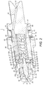
Figure 11 shows schematically flow paths of a fuel and a cleaning fluid through the fuel injector ofFigure 2 . - As illustrated in
Figure 1 , a fuel injection assembly according to the present disclosure comprises afuel injection pump 2, acleaning fluid pump 3 and a fuel injector 1. The fuel injection assembly may be configured for use with an internal combustion engine, preferably a C.I. engine. Thefuel injection pump 2 is connected to the fuel injector 1 by a fuel supply conduit 4. Thefuel injection pump 2 may be integrated with the fuel injector 1 as a single component or may be a separate component. Thefuel injection pump 2 may be driven off an elliptical cam to produce a cyclical increase and decrease in the pressure of the fuel supplied by thefuel injection pump 2 to the fuel supply conduit 4. Thecleaning fluid pump 3 may be connected to the fuel injector 1 via acleaning fluid sensor 6 by means of a cleaningfluid supply conduit 5. Thecleaning fluid pump 3 may be integrated with the fuel injector 1 as a single component or may be a separate component. Afuel leakage conduit 7 may be provided in communication with the fuel injector 1 and thefuel leakage conduit 7 may have a pressure-regulatingvalve 18 to control flow of fluid therethrough. - As shown in
Figures 2 and3 , the fuel injector 1 may comprise afuel injector body 10 which may house avalve member 11, avalve member guide 12, anintermediate body 14 and aspring chamber housing 13. Acollar 15 may also be associated with thefuel injector body 10 as will be described further below. Thefuel injector body 10 may be a generally cylindrical component having a stepped diameter and may have a hollow central bore for receiving thevalve member guide 12, theintermediate body 14 and the spring chamber housing 13. - The
valve member guide 12 is shown inFigures 4 to 6 . Thevalve member guide 12 may be a generally cylindrical component having a stepped diameter with a narrower portion at one end which may terminate in an aperture which may define afuel injector outlet 21 and a wider portion at an opposite end which may be provided with a firstannular fuel gallery 32. Thevalve member guide 12 defines abore 23 which may pass along the central axis of thevalve member guide 12 from afirst end 24 proximate thefuel injector outlet 21 to asecond end 25 distal thefuel injector outlet 21. - A
fuel supply passage 80 may be provided that passes through an interior of the fuel injector 1 from afuel inlet port 81 to anoutlet chamber 22. - Two
inclined passages 80a, forming a part of thefuel supply passage 80, may be provided which extend from the firstannular fuel gallery 32 to theoutlet chamber 22 which may be provided in the region of thefuel injector outlet 21. Theoutlet chamber 22 is in fluid communication with both thebore 23 and thefuel injector outlet 21. Thefuel injector outlet 21 may be surrounded by avalve seat 20 which may be in the form of a conical surface of thevalve member guide 12. Anannular drainage gallery 26 may be provided in thevalve member guide 12 located in between thefirst end 24 andsecond end 25 of thebore 23. As shown, theannular drainage gallery 26 may be located approximately midway between thefirst end 24 andsecond end 25. Theannular drainage gallery 26 may be in the form of an enlarged diameter portion of thebore 23. Adrainage port 27 may be provided in theannular drainage gallery 26 which may connect to adrainage passage 28 to provide fluid communication between theannular drainage gallery 26 and an exterior surface of thevalve member guide 12 as shown inFigure 6 . Thedrainage passage 28 is also shown inFigure 3 and in dashed lines inFigure 11 where it can be seen that thedrainage passage 28 may extend away from thebore 23. - The
intermediate body 14 is shown inFigures 7 and 8 and may typically comprise a disc-shaped body provided on a face distal thefuel injector outlet 21 with a secondannular fuel gallery 61. Twoperipheral passages 80b, forming a part of thefuel supply passage 80, may be provided which extend through theintermediate body 14 into fluid communication with the secondannular fuel gallery 61. Theintermediate body 14 may further be provided with acentral bore 60 which may pass through the length of theintermediate body 14. - The
valve member 11 may comprise a cylindrical elongate body of varying shape and diameter which is sized and shaped to be received as a sliding fit within thebore 23 of thevalve member guide 12. Thevalve member 11 may have a diameter at its largest point of from 4 to 11 mm. Afirst end 8 of thevalve member 11 may be sized and shaped to form a sealing contact with thevalve seat 20 of thevalve member guide 12. A second end 9 of thevalve member 11 may be sized and shaped to pass through thecentral bore 60 of theintermediate body 14. Aspring seat plug 17 may be received over the second end 9 of thevalve member 11 as shown inFigures 2 and3 . - The
spring chamber housing 13 is shown inFigure 9 and may generally comprise a cylindrical body having a stepped diameter having two relatively narrow portions at either end of thespring chamber housing 13 and an enlarged diameter portion approximately mid-way along the length of thespring chamber housing 13. Thespring chamber housing 13 may define aspring chamber 40 in which may be contained or have connected thereto a device for producing a biasing force. The biasing force may be, for example, a mechanically-generated force or a hydraulically-generated force. In the case of a mechanically-generated force, this may be produced by a biasingmember 50 or similar device. In the example ofFigures 2 and3 the biasingmember 50 is a compression spring. Thespring chamber 40 may have afirst end 43 proximate thefuel injector outlet 21 and asecond end 44 distal thefuel injector outlet 21. Anentry port 41 may be provided at or near thesecond end 44 of thespring chamber 40 which communicates with a cleaningfluid inlet port 91 at an exterior of thespring chamber housing 13 via a cleaningfluid supply passage 90 to be able in use to receive pressurised cleaning fluid. In addition, thespring chamber housing 13 may be provided with a dog-leg passage 80c, forming a part of thefuel supply passage 80, which extends from thefuel inlet port 81 located at a distal end of thespring chamber housing 13 through the length of thespring chamber housing 13. The dog-leg passage 80c may by-pass thespring chamber 40 so that it does not enter or pass through thespring chamber 40. In addition, the dog-leg passage 80c may be separate from the cleaningfluid supply passage 90. - The
collar 15 is shown inFigure 10 and typically may comprise a cylindrical member havingannular recesses 71 on each face and adrain exit port 70 which may be in the form of a through aperture passing through the wall of thecollar 15 as shown inFigures 10 and11 . - When assembled and in a closed configuration, as shown in
Figures 2 and3 , thevalve member guide 12,intermediate body 14 andspring chamber housing 13 may be stacked in longitudinal arrangement and retained within thefuel injector body 10. The surfaces of thevalve member guide 12,intermediate body 14 andspring chamber housing 13 which interface with each other by way of contact may have a polished metal finish creating a fluid-tight seal therebetween. A firstannular clearance 30 may be provided between an inner surface of thefuel injector body 10 and an outer surface of thevalve member guide 12 as shown inFigure 2 . In addition, a secondannular clearance 31 may be provided between the inner surface of thefuel injector body 10 and an outer surface of thespring chamber housing 13. - When assembled and in the closed configuration the
valve member 11 is located at least partially within thebore 23 of thevalve member guide 12 with itsfirst end 8 extending into contact with thevalve seat 20 and its second end 9 passing through thecentral bore 60 of theintermediate body 14 into thespring chamber 40. Thespring seat plug 17, also located within thespring chamber 40 is received on the second end 9 of thevalve member 11. The biasingmember 50 may be located within thespring chamber 40 extending between thesecond end 44 of thespring chamber 40 and the spring seat plug 17 located at thefirst end 43 of thespring chamber 40. In this way the biasingmember 50 may bias thevalve member 11 into the closed configuration as shown inFigures 2 and3 . To enable sliding relative movement of thevalve member 11 with respect to thevalve member guide 12 the diameter of thebore 23 must be made slightly greater than the diameter of thevalve member 11. In this way aclearance 29, which may be an annular clearance, is provided between thevalve member 11 and thevalve member guide 12. Theclearance 29 may be kept small and may be, for example, an annular (diametrical) clearance of a few microns. - The
collar 15 may be located between an end of thefuel injector body 10 and the enlarged diameter portion of thespring chamber housing 13. An O-ring 16 may be located in each of theannular recesses 71 of thecollar 15 to provide a fluid seal between the collar and respectively thefuel injector body 10 and thespring chamber housing 13. - In use, the
fuel injection pump 2 operates to supply pressurised fuel to thefuel inlet port 81. The cleaningfluid pump 3 operates to supply pressurised cleaning fluid to the cleaningfluid inlet port 91. The pressurised cleaning fluid may be supplied to the cleaningfluid inlet port 91 continuously, so that pressurised cleaning fluid is supplied to the fuel injector 1 throughout injection of fuel by the fuel injector 1. - As most clearly shown in
Figures 2 and11 both a flow path for fuel and a flow path for cleaning fluid may be provided through the fuel injector 1. InFigure 11 the flow path of the fuel is designated by reference 'F' and the flow path of the cleaning fluid is shown by reference 'C'. As shown, the flow paths for the fuel F and the cleaning fluid C may combine during their routes through the fuel injector 1. - The flow path for fuel F extends from the
fuel inlet port 81 provided in the distal end of thespring chamber housing 13 and passes along the dog-leg passage 80c of thespring chamber housing 13 and into the secondannular fuel gallery 61 of theintermediate body 14. The secondannular fuel gallery 61 ensures fluid communication between the dog-leg passage 80c and thespring chamber housing 13 and the twoperipheral passages 80b in theintermediate body 14 irrespective of the annular orientation of thespring chamber housing 13 relative to theintermediate body 14. The fuel path for fuel F then passes through the twoperipheral passages 80b into the firstannular fuel gallery 32 of thevalve member guide 12. Again, the firstannular fuel gallery 32 ensures fluid communication between the twoperipheral passages 80b and the twoinclined passages 80a within thevalve member guide 12 irrespective of the annular orientation of thevalve member guide 12 with respect to theintermediate body 14. Thereafter the flow path for fuel F passes along the twoinclined passages 80a within thevalve member guide 12 into theoutlet chamber 22 located proximate to thefuel injector outlet 21. - As shown in
Figures 2 and11 , initially discharge of fuel out of thefuel injector outlet 21 is prevented by the sealing contact between thevalve member 11 and thevalve seat 20. However, due to pressurisation of the fuel within theoutlet chamber 22, due to action of thefuel injection pump 2, a point will be reached at which the pressure within theoutlet chamber 22 acting on thefirst end 8 of thevalve member 11 will be sufficient to overcome the biasing force of the biasingmember 50. The fuel injector 1 may be configured to operate at high pressures such that the pressure in theoutlet chamber 22 may reach in excess of 100 bar before the biasing force of the biasingmember 50 is overcome. At this point, thevalve member 11 will lift off thevalve seat 20 by sliding axially within thebore 23 away from thefuel injector outlet 21 which opens thefuel injector outlet 21 allowing discharge of fuel. An interior of the fuel injector 1 may reach in excess of 1000 bar during parts of the operating cycle. Discharge of the fuel leads to a reduction in pressure of the fuel within theoutlet chamber 22 resulting in resealing of thevalve member 11 against thevalve seat 20 under action of the biasingmember 50. Thus, in this way, in conjunction with the cyclical increase and decrease in the pressure of the supplied fuel from thefuel injection pump 2, a cyclical opening and shutting of thefuel injector outlet 21 may be achieved. - During operation, fuel in the
outlet chamber 22 may leak in between thevalve member 11 and thevalve member guide 12 along thebore 23 in theclearance 29 which is provided between thevalve member 11 and thevalve member guide 12, even though theclearance 29 is preferably kept very small. Left unrestricted it may be possible for the fuel to pass along the full length of thebore 23, then through thecentral bore 60 of theintermediate body 14 and into thespring chamber 40. - According to the present disclosure, this may be prevented by the combined action of the pressurised cleaning fluid which is supplied into the cleaning
fluid inlet port 91 and through the cleaningfluid supply passage 90 into thespring chamber 40 and the provision of theannular drainage gallery 26 anddrainage port 27. As shown, the pressurised cleaning fluid in thespring chamber 40 is in fluid communication with thecentral bore 60 of theintermediate body 14 and thesecond end 25 of thebore 23. Thus, thecentral bore 60 may act as an exit port from thespring chamber 40 for the pressurised cleaning fluid. By suitable configuration of the pressure of the pressurised cleaning fluid, it may be ensured that any leakage of the fuel along thebore 23 through theclearance 29 does not reach thespring chamber 40. This may be ensured by configuring the pressure of the pressurised cleaning fluid so that there is during operation of the fuel injector 1 a small volumetric flow of pressurised cleaning fluid from thespring chamber 40 into thebore 23. Thus, thespring chamber 40 may form a part of the cleaningfluid supply passage 90 linking the cleaningfluid inlet port 91 with thebore 23. - In practice, the pressure of the pressurised cleaning fluid may be configured by operation of the cleaning
fluid pump 3 to be greater than the pressure of the fuel in theannular drainage gallery 26. Thus, the presence of the pressurised cleaning fluid in thespring chamber 40, and optionally the entry of the pressurised cleaning fluid into thesecond end 25 of thebore 23, restricts flow of the fuel into thespring chamber 40. By 'restricts' is meant that the amount of fuel reaching thespring chamber 40 is reduced and/or the volumetric flow rate of the fuel into thespring chamber 40 is reduced compared to an arrangement where the pressurised cleaning fluid is not supplied. - In order to accommodate a flow of the pressurised cleaning fluid into the
second end 25 of thebore 23, drainage of the pressurised cleaning fluid from thebore 23, may be provided for by the provision of theannular drainage gallery 26,drainage port 27 anddrainage passage 28. As can be seen inFigure 11 , the pressurised cleaning fluid passing from thespring chamber 40 into thebore 23 passes along theclearance 29 until it reaches theannular drainage gallery 26. From theannular drainage gallery 26 the pressurised cleaning fluid is then drained through thedrainage port 27 and along thedrainage passage 28 into the firstannular clearance 30 between thefuel injector body 10 and thevalve member guide 12. From there it may drain into the secondannular clearance 31 between thefuel injector body 10 and thespring chamber housing 13. Finally, the pressurised cleaning fluid may be drained out of thedrain exit port 70 of thecollar 15 into thefuel leakage conduit 7 which may be coupled to thedrain exit port 70. Drainage of the pressurised cleaning fluid from thedrain exit port 70 may be passive, i.e. driven by the back-pressure of the pressurised cleaning fluid entering the fuel injector 1 at the cleaningfluid inlet port 91. Preferably the pressurised cleaning fluid is configured, for example by suitable adjustment of its pressure by use of the pressure-regulatingvalve 18, to prevent any fuel reaching thespring chamber 40 during normal operation of the fuel injector 1 and also may ideally be configured so there is little or no leakage of pressurised cleaning fluid through theannular drainage gallery 26 and thedrainage port 27. As will be understood, it may be preferable in this way to ensure that theannular drainage gallery 26 and theclearance 29 between theannular drainage gallery 26 and thesecond end 25 of thebore 23 are always full of pressurised cleaning fluid (so as to most efficiently restrict passage of fuel towards the spring chamber 40) but to limit or prevent any substantial net flow of pressurised cleaning fluid through the fuel injector 1 (so as to limit wastage of the pressurised cleaning fluid). - In addition, and simultaneously to the flow of the pressurised cleaning fluid, any fuel which may leak from the
outlet chamber 22 along thebore 23 upon reaching theannular drainage gallery 26 may be diverted and drained through thedrainage port 27,drainage passage 28, firstannular clearance 30 and secondannular clearance 31 along with the pressurised cleaning fluid. Thus, in this way fuel may be prevented from reaching not only thespring chamber 40 but also thesecond end 25 of thebore 23. - In this way leakage fuel and pressurised cleaning fluid may be drained from the fuel injector 1 via the
fuel leakage conduit 7 and pressure-regulatingvalve 18. The pressure-regulatingvalve 18 may be used to create a 'pulsing' reciprocating flow of the pressurised cleaning fluid within the passages of the fuel injector 1. For example, as will be understood, during an operating cycle of the fuel injector 1 the pressure of the fuel in the fuel injector will vary and may reach very high pressures (in excess of 1000 bar) but typically for only a very small proportion of the operating cycle. During such peak pressures any leakage fuel and pressurised cleaning fluid in theclearance 29 may tend to be driven up theclearance 29 towards thespring chamber 40 due to the fact that the pressure of the pressurised cleaning fluid is much less than the peak fuel pressure - e.g. the pressure of the pressurised cleaning fluid may of the order of 10 bar. During a remainder of the operating cycle the pressure of the pressurised cleaning fluid is higher than the fuel pressure and any leakage fuel and pressurised cleaning fluid in the clearance may be driven back along theclearance 29 away from thespring chamber 40. In this way a reciprocating flow of the pressurised cleaning fluid, in particular, may be produced in theclearance 29 which may be particularly effective for cleaning and lubrication of the fuel injector 1 components. - It will be noted that the
drainage passage 28 and the flow path to thedrain exit port 70 may by-pass thespring chamber 40. In addition, at least a portion of the drainage path may extend along an interface of thefuel injector body 10 and thevalve member guide 12 and/or an interface of thefuel injector body 10 and thespring chamber housing 13. - The fuel injected by the fuel injector 1 may be of any type suitable for injection. The fuel may be a fossil fuel or biofuel. Typical examples may include petrol, diesel and biodiesel. The fuel injector 1 of the present disclosure may find particular application when used with fuels that are relatively sensitive to heat such as biomass derived oils and liquid pyrolysis fuels.
- The cleaning fluid may be any suitable agent that is compatible with the materials of the fuel injector 1, and with the fuel, and which may act to break up and remove deposits of the fuel and/or combustion products produced from the fuel. Optionally, the cleaning fluid may also act as a lubricant for components of the fuel injector 1. In one example the cleaning fluid may be a blend of ethanol and castor oil. The blend may comprise, for example, a 50:50 blend of ethanol and castor oil.
- The components of the fuel injector 1 may be made of standard materials, for example, the
fuel injector body 10,valve member 11,valve member guide 12,intermediate body 14,spring chamber housing 13 andcollar 15 may all be formed of tool steel, for example of grade 52-100. The O-rings 16 may be a suitable elastomeric material which is compatible with the fuel and cleaning fluid. However, in a case where the fuel F may be of a more corrosive type those components subject to dynamic wear, for example thevalve member 11 and thevalve member guide 12, may be made of a more corrosion-resistant material such as stainless steel. - The cleaning
fluid sensor 6, as shown inFigure 1 , may be configured to sense a volumetric flow rate or volume of the cleaning fluid conveyed, in use, through the cleaningfluid supply conduit 5. - Operation of the fuel injection assembly may comprise simultaneously operating the
fuel injection pump 2 to supply a pressurised flow of fuel to theoutlet chamber 22 of the fuel injector 1 via thefuel supply passage 80 and operating the cleaningfluid pump 3 to supply a pressurised flow of cleaning fluid to thesecond end 25 of thebore 23 of the fuel injector 1 via the cleaning fluid supply passage 90.The pressure of the cleaning fluid at thesecond end 25 of thebore 23 of the fuel injector 1 may be configured to be sufficient to create a flow of the cleaning fluid between thevalve member 11 andvalve member guide 12 towards thefuel injector outlet 21 for at least a portion of an operating cycle of the fuel injector 1. In addition, the lift-off pressure for theoutlet chamber 22 of the fuel injector 1 at which thevalve member 11 will move out of contact with thevalve seat 20 may be pre-set to take into account the effect of the pressure of the pressurised flow of cleaning fluid which may always be exposed to thesecond end 25 of thebore 23. For example, the biasing force supplied by the biasingmember 50 may be pre-adjusted by use of ashim 45 located between the biasingmember 50 and an end of thespring chamber 40. Thus, the biasing force applied to thevalve member 11 may be adjusted by altering the thickness of theshim 45 installed. - The fuel injection assembly may also be operated to maintain a diagnostic check of the state of health of the fuel injector 1. Over time the surfaces of the
valve member 11 and thebore 23 may be subject to degradation due to friction and/or corrosive effects of the fuel. This may lead to an increase in the effective cross-sectional area of theclearance 29 between thevalve member 11 and thevalve member guide 12. An increase in the effective cross-sectional area of theclearance 29 will lead to a reduced resistance to passage of the pressurised cleaning fluid along thebore 23. Thus, the cleaningfluid sensor 6 may be configured to detect a rate and/or volume of flow of cleaning fluid passing through the cleaningfluid supply conduit 5. For a fuel injector 1 in a healthy state a required rate and/or volume of flow of cleaning fluid can be determined by experiment. Thereafter, a suitable control means such as an engine control unit or other controller can be used to monitor and detect any significant increase in the rate and/or volume of flow of cleaning fluid passing the cleaningfluid sensor 6 into the fuel injector 1. A threshold value for the rate and/or volume of flow may be set at which an alert is raised which may trigger a maintenance inspection and/or replacement of the fuel injector 1. Alternatively, the cleaningfluid sensor 6 could be located downstream of the fuel injector 1, e.g. within thefuel leakage conduit 7 or pressure-regulatingvalve 18. - In this description the fuel injector 1 has been described by way of example only as comprising a
valve member 11 that is moved relative to avalve seat 20 by hydraulic buildup of pressure of the fuel accumulating in anoutlet chamber 22. However, the present disclosure and claims are not limited in this regard and may also be applicable to fuel injectors provided with other devices or methods for moving thevalve member 11, for example the use of a magnetically-driven actuator, for example a solenoid, coupled to thevalve member 11, or a method of creating a cyclically-changing pressure differential across thevalve member 11. - The present disclosure provides a fuel injector 1, a fuel injection assembly and methods of operation that may advantageously allow for improved reliability and durability of the fuel injector 1. By means of ensuring that the fuel does not enter the
spring chamber 40, e.g. thefuel supply passage 80 by-passes thespring chamber 40, and thus contact the biasingmember 50, formation of fuel deposits and/or laquer in the region of the biasingmember 50 may be reduced and/or prevented. This may lead to a reduced likelihood of jamming of the fuel injector 1 in use. In addition, the fuel injector 1 and the fuel injection assembly may allow for a beneficial diagnostic check of the state of the fuel injector 1 to be carried out by means of monitoring the volumetric flow rate and/or volume of the pressurised cleaning fluid entering the fuel injector 1. This may allow for improved maintenance by allowing for replacement and/or cleaning of the fuel to be carried out before a failure mode is encountered.
Claims (15)
- A fuel injector comprising a valve member, a valve member guide, a spring chamber, a fuel supply passage and a cleaning fluid supply passage;
the valve member being movable with respect to the valve member guide into and out of contact with a valve seat of the fuel injector to thereby control discharge of a fuel out of a fuel injector outlet;
the valve member guide defining a bore which receives the valve member, the bore being configured to guide the valve member during sliding movement of the valve member into and out of contact with the valve seat, the bore comprising a first end proximate the fuel injector outlet and a second end distal the fuel injector outlet;
the spring chamber containing a biasing member which biases the valve member into contact with the valve seat;
the fuel supply passage being configured to direct a flow of the fuel to an outlet chamber of the fuel injector, the outlet chamber being in fluid communication with the first end of the bore and the valve member; wherein the fuel supply passage by-passes the spring chamber;
the cleaning fluid supply passage being in fluid communication with the second end of the bore and configured to supply a pressurised cleaning fluid to the second end of the bore to restrict leakage of the fuel from the outlet chamber towards the second end of the bore along a clearance extending between the valve member and the valve member guide. - A fuel injector as claimed in claim 1, wherein pressurisation of the fuel within the outlet chamber enables sliding movement of the valve member away from the fuel injector outlet to thereby lift off the valve member from the valve seat to allow discharge of fuel from the outlet chamber out of the fuel injector outlet.
- A fuel injector as claimed in claim 1 or claim 2, wherein the biasing member is a spring, or a magnetically-driven actuator.
- A fuel injector as claimed in any preceding claim, wherein the spring chamber forms a part of the cleaning fluid supply passage.
- A fuel injector as claimed in claim 4, wherein the spring chamber comprises an entry port to receive pressurised cleaning fluid and an exit port in fluid communication with the second end of the bore, wherein optionally the exit port is located at a first end of the spring chamber proximate the fuel injector outlet and the entry port is located at a second end of the spring chamber distal the fuel injector outlet.
- A fuel injector as claimed in any preceding claim, wherein the valve member guide comprises a drainage port in fluid communication with the bore and located between the first end and the second end of the bore, the drainage port also being in fluid communication with a drainage passage which extends away from the bore.
- A fuel injector as claimed in claim 6, wherein the valve member guide comprises an annular drainage gallery in fluid communication with the bore and the drainage port.
- A fuel injector as claimed in claim 6 or claim 7, wherein the drainage passage by-passes the spring chamber.
- A fuel injector as claimed in any of claims 6 to 8, further comprising a fuel injector body which retains the valve member guide, wherein at least a portion of a drainage path extends along an interface of the fuel injector body and the valve member guide.
- A fuel injector as claimed in claim 9, wherein at least a portion of the drainage path extends along an interface of the fuel injector body and a housing of the spring chamber.
- A fuel injection assembly comprising a fuel injection pump, a cleaning fluid pump and a fuel injector as claimed in any preceding claim;
the fuel injection pump comprising a fuel supply conduit in fluid communication with the fuel supply passage of the fuel injector; and
the cleaning fluid pump comprising a cleaning fluid supply conduit in fluid communication with the cleaning fluid supply passage of the fuel injector. - The fuel injection assembly of claim 11, further comprising a cleaning fluid sensor configured to sense a volumetric flow rate or volume of a cleaning fluid conveyed, in use, through the cleaning fluid supply conduit.
- A method of operating a fuel injection assembly as claimed in claim 11 or claim 12, comprising simultaneously operating the fuel injection pump to supply a pressurised flow of fuel to the outlet chamber of the fuel injector via the fuel supply passage and operating the cleaning fluid pump to supply a pressurised flow of cleaning fluid to the second end of the bore of the fuel injector via the cleaning fluid supply passage.
- The method of claim 13, further comprising the step of configuring the pressure of the cleaning fluid at the second end of the bore of the fuel injector to be sufficient to create a flow of the cleaning fluid between the valve member and valve member guide towards the fuel injector outlet.
- The method of claim 13 or claim 14, further comprising the step of configuring a biasing force supplied by a biasing member of the fuel injector in conjunction with configuring a pressure of the pressurised flow of cleaning fluid to enable pre-setting of a lift-off pressure for the outlet chamber of the fuel injector at which the valve member will move out of contact with the valve seat.
Applications Claiming Priority (1)
| Application Number | Priority Date | Filing Date | Title |
|---|---|---|---|
| GB1519224.8A GB2543826B (en) | 2015-10-30 | 2015-10-30 | A fuel injector, a fuel injector assembly and an associated method |
Publications (2)
| Publication Number | Publication Date |
|---|---|
| EP3163067A1 true EP3163067A1 (en) | 2017-05-03 |
| EP3163067B1 EP3163067B1 (en) | 2020-03-18 |
Family
ID=55130468
Family Applications (1)
| Application Number | Title | Priority Date | Filing Date |
|---|---|---|---|
| EP16196061.2A Active EP3163067B1 (en) | 2015-10-30 | 2016-10-27 | A fuel injector, a fuel injector assembly and an associated method |
Country Status (4)
| Country | Link |
|---|---|
| US (1) | US10851753B2 (en) |
| EP (1) | EP3163067B1 (en) |
| CN (1) | CN106640464B (en) |
| GB (1) | GB2543826B (en) |
Families Citing this family (4)
| Publication number | Priority date | Publication date | Assignee | Title |
|---|---|---|---|---|
| GB2543826B (en) | 2015-10-30 | 2019-07-24 | Caterpillar Inc | A fuel injector, a fuel injector assembly and an associated method |
| US10584669B2 (en) * | 2017-11-29 | 2020-03-10 | Caterpillar Inc. | Filter assembly for fuel injector |
| US11885291B2 (en) * | 2019-05-03 | 2024-01-30 | Walbro Llc | Low pressure fuel injection system for a combustion engine |
| CN111535958B (en) * | 2020-05-29 | 2021-07-13 | 一汽解放汽车有限公司 | Dual-fuel injector and injection method thereof |
Citations (5)
| Publication number | Priority date | Publication date | Assignee | Title |
|---|---|---|---|---|
| GB2051234A (en) * | 1979-06-02 | 1981-01-14 | Daimler Benz Ag | Fuel injection valve with ducts for a supplementary fluid |
| EP0064146A1 (en) * | 1981-05-06 | 1982-11-10 | Klöckner-Humboldt-Deutz Aktiengesellschaft | Injection system for injecting two fuels through one injection nozzle |
| WO2008000095A1 (en) * | 2006-06-29 | 2008-01-03 | The University Of British Columbia | Concurrent injection of liquid and gaseous fuels in an engine |
| JP2008121545A (en) * | 2006-11-10 | 2008-05-29 | Mitsubishi Heavy Ind Ltd | Fuel injection device |
| DE112011105459T5 (en) * | 2011-07-22 | 2014-04-17 | Hitachi Construction Machinery Co., Ltd. | Injector, fuel injection system and thus provided construction machine |
Family Cites Families (14)
| Publication number | Priority date | Publication date | Assignee | Title |
|---|---|---|---|---|
| US4856713A (en) * | 1988-08-04 | 1989-08-15 | Energy Conservation Innovations, Inc. | Dual-fuel injector |
| US5339845A (en) | 1993-07-26 | 1994-08-23 | Fuel Systems Textron, Inc. | Cleaning apparatus and method for fuel and other passages |
| DE69628979T2 (en) | 1995-08-18 | 2004-02-12 | Orbital Engine Co. (Australia) Pty. Ltd., Balcatta | Fuel injection system for internal combustion engines |
| US6234002B1 (en) * | 1997-09-05 | 2001-05-22 | David W. Sisney | Apparatus and methods for cleaning and testing fuel injectors |
| WO2000063552A1 (en) | 1999-04-20 | 2000-10-26 | Grigoli Kvaratskhelia | Device and method for cleaning of internal combustion engine fuel injector |
| DE10033428C2 (en) * | 2000-07-10 | 2002-07-11 | Bosch Gmbh Robert | Pressure controlled injector for injecting fuel |
| US20060060673A1 (en) * | 2000-11-22 | 2006-03-23 | Gerhard Mack | Injector with separately controllable injector needles |
| DE10123867A1 (en) * | 2001-05-16 | 2002-11-28 | Bosch Gmbh Robert | Fuel injector |
| DE10314454B4 (en) * | 2003-03-30 | 2009-04-09 | Robert Bosch Gmbh | Vacuum flushing of an injector for internal combustion engines |
| US20080295492A1 (en) * | 2007-05-31 | 2008-12-04 | Caterpillar Inc. | Injector cleaning system based on pressure decay |
| US20110220150A1 (en) * | 2010-03-09 | 2011-09-15 | International Engine Intellectual Property Company, Llc | Cone nut inside diameter cleaning |
| US20120055514A1 (en) * | 2010-03-09 | 2012-03-08 | Philip James Charles Vince | Rail connection restoration and method for cleaning fuel injector without disassembly |
| KR101235566B1 (en) | 2012-07-05 | 2013-02-21 | (주)씨앤포스 | Apparatus for cleaning injectors of an diesel engine |
| GB2543826B (en) * | 2015-10-30 | 2019-07-24 | Caterpillar Inc | A fuel injector, a fuel injector assembly and an associated method |
-
2015
- 2015-10-30 GB GB1519224.8A patent/GB2543826B/en active Active
-
2016
- 2016-10-25 CN CN201610941700.XA patent/CN106640464B/en active Active
- 2016-10-26 US US15/335,066 patent/US10851753B2/en active Active
- 2016-10-27 EP EP16196061.2A patent/EP3163067B1/en active Active
Patent Citations (5)
| Publication number | Priority date | Publication date | Assignee | Title |
|---|---|---|---|---|
| GB2051234A (en) * | 1979-06-02 | 1981-01-14 | Daimler Benz Ag | Fuel injection valve with ducts for a supplementary fluid |
| EP0064146A1 (en) * | 1981-05-06 | 1982-11-10 | Klöckner-Humboldt-Deutz Aktiengesellschaft | Injection system for injecting two fuels through one injection nozzle |
| WO2008000095A1 (en) * | 2006-06-29 | 2008-01-03 | The University Of British Columbia | Concurrent injection of liquid and gaseous fuels in an engine |
| JP2008121545A (en) * | 2006-11-10 | 2008-05-29 | Mitsubishi Heavy Ind Ltd | Fuel injection device |
| DE112011105459T5 (en) * | 2011-07-22 | 2014-04-17 | Hitachi Construction Machinery Co., Ltd. | Injector, fuel injection system and thus provided construction machine |
Also Published As
| Publication number | Publication date |
|---|---|
| GB2543826B (en) | 2019-07-24 |
| CN106640464A (en) | 2017-05-10 |
| EP3163067B1 (en) | 2020-03-18 |
| US20170122280A1 (en) | 2017-05-04 |
| US10851753B2 (en) | 2020-12-01 |
| GB2543826A (en) | 2017-05-03 |
| GB201519224D0 (en) | 2015-12-16 |
| CN106640464B (en) | 2021-06-04 |
Similar Documents
| Publication | Publication Date | Title |
|---|---|---|
| EP3163067B1 (en) | A fuel injector, a fuel injector assembly and an associated method | |
| US8662411B2 (en) | Fuel injection valve for internal combustion engines | |
| US7690588B2 (en) | Fuel injector nozzle with flow restricting device | |
| US10865718B2 (en) | Pressure regulating modules with controlled leak paths | |
| US7040293B2 (en) | Fuel injection system | |
| KR102513339B1 (en) | fuel injector valve | |
| CN101910605A (en) | Over time motor and control valve assembly in operating have been reduced | |
| FI123334B (en) | Safety valve arrangement for common rail fuel injection system and common rail fuel injection system | |
| CN113795665A (en) | Fuel system with fixed geometry flow control valve for limiting injector cross talk | |
| EP3180510B1 (en) | A fuel injection valve arrangement for internal combustion engine | |
| US10378500B2 (en) | Protection device for limiting pump cavitation in common rail system | |
| EP0844383B1 (en) | Injector | |
| RU2555097C2 (en) | Pump for diesel oil feed into ice | |
| EP2354530B1 (en) | Needle for needle valve | |
| US7661410B1 (en) | Fluid leak limiter | |
| EP3017184B1 (en) | Fuel injection system | |
| US6192870B1 (en) | Fuel injector | |
| US20140182550A1 (en) | Quill with Integrated Flow Limiter | |
| WO2014072678A2 (en) | A pump assembly and a valve | |
| EP2420667A1 (en) | Fuel injector with damper volume and method for controlling pressure overshoot | |
| WO2015124340A1 (en) | Fuel injector | |
| EP2508745B1 (en) | Fuel injection system including a purging system for purging an injection nozzle in operation with pyrolysis fuel oil | |
| US20150097049A1 (en) | Decoupled Needle Control Assembly | |
| JP3788048B2 (en) | Accumulated fuel injection system | |
| WO2009127868A1 (en) | Fuel injector |
Legal Events
| Date | Code | Title | Description |
|---|---|---|---|
| PUAI | Public reference made under article 153(3) epc to a published international application that has entered the european phase |
Free format text: ORIGINAL CODE: 0009012 |
|
| STAA | Information on the status of an ep patent application or granted ep patent |
Free format text: STATUS: THE APPLICATION HAS BEEN PUBLISHED |
|
| AK | Designated contracting states |
Kind code of ref document: A1 Designated state(s): AL AT BE BG CH CY CZ DE DK EE ES FI FR GB GR HR HU IE IS IT LI LT LU LV MC MK MT NL NO PL PT RO RS SE SI SK SM TR |
|
| AX | Request for extension of the european patent |
Extension state: BA ME |
|
| STAA | Information on the status of an ep patent application or granted ep patent |
Free format text: STATUS: REQUEST FOR EXAMINATION WAS MADE |
|
| 17P | Request for examination filed |
Effective date: 20171030 |
|
| RBV | Designated contracting states (corrected) |
Designated state(s): AL AT BE BG CH CY CZ DE DK EE ES FI FR GB GR HR HU IE IS IT LI LT LU LV MC MK MT NL NO PL PT RO RS SE SI SK SM TR |
|
| STAA | Information on the status of an ep patent application or granted ep patent |
Free format text: STATUS: EXAMINATION IS IN PROGRESS |
|
| 17Q | First examination report despatched |
Effective date: 20181026 |
|
| GRAP | Despatch of communication of intention to grant a patent |
Free format text: ORIGINAL CODE: EPIDOSNIGR1 |
|
| STAA | Information on the status of an ep patent application or granted ep patent |
Free format text: STATUS: GRANT OF PATENT IS INTENDED |
|
| INTG | Intention to grant announced |
Effective date: 20191008 |
|
| GRAS | Grant fee paid |
Free format text: ORIGINAL CODE: EPIDOSNIGR3 |
|
| GRAA | (expected) grant |
Free format text: ORIGINAL CODE: 0009210 |
|
| STAA | Information on the status of an ep patent application or granted ep patent |
Free format text: STATUS: THE PATENT HAS BEEN GRANTED |
|
| RAP1 | Party data changed (applicant data changed or rights of an application transferred) |
Owner name: CATERPILLAR INC. |
|
| AK | Designated contracting states |
Kind code of ref document: B1 Designated state(s): AL AT BE BG CH CY CZ DE DK EE ES FI FR GB GR HR HU IE IS IT LI LT LU LV MC MK MT NL NO PL PT RO RS SE SI SK SM TR |
|
| REG | Reference to a national code |
Ref country code: GB Ref legal event code: FG4D |
|
| REG | Reference to a national code |
Ref country code: DE Ref legal event code: R096 Ref document number: 602016031905 Country of ref document: DE |
|
| REG | Reference to a national code |
Ref country code: AT Ref legal event code: REF Ref document number: 1246177 Country of ref document: AT Kind code of ref document: T Effective date: 20200415 Ref country code: IE Ref legal event code: FG4D |
|
| PG25 | Lapsed in a contracting state [announced via postgrant information from national office to epo] |
Ref country code: NO Free format text: LAPSE BECAUSE OF FAILURE TO SUBMIT A TRANSLATION OF THE DESCRIPTION OR TO PAY THE FEE WITHIN THE PRESCRIBED TIME-LIMIT Effective date: 20200618 Ref country code: RS Free format text: LAPSE BECAUSE OF FAILURE TO SUBMIT A TRANSLATION OF THE DESCRIPTION OR TO PAY THE FEE WITHIN THE PRESCRIBED TIME-LIMIT Effective date: 20200318 Ref country code: FI Free format text: LAPSE BECAUSE OF FAILURE TO SUBMIT A TRANSLATION OF THE DESCRIPTION OR TO PAY THE FEE WITHIN THE PRESCRIBED TIME-LIMIT Effective date: 20200318 |
|
| REG | Reference to a national code |
Ref country code: NL Ref legal event code: MP Effective date: 20200318 |
|
| PG25 | Lapsed in a contracting state [announced via postgrant information from national office to epo] |
Ref country code: HR Free format text: LAPSE BECAUSE OF FAILURE TO SUBMIT A TRANSLATION OF THE DESCRIPTION OR TO PAY THE FEE WITHIN THE PRESCRIBED TIME-LIMIT Effective date: 20200318 Ref country code: GR Free format text: LAPSE BECAUSE OF FAILURE TO SUBMIT A TRANSLATION OF THE DESCRIPTION OR TO PAY THE FEE WITHIN THE PRESCRIBED TIME-LIMIT Effective date: 20200619 Ref country code: LV Free format text: LAPSE BECAUSE OF FAILURE TO SUBMIT A TRANSLATION OF THE DESCRIPTION OR TO PAY THE FEE WITHIN THE PRESCRIBED TIME-LIMIT Effective date: 20200318 Ref country code: BG Free format text: LAPSE BECAUSE OF FAILURE TO SUBMIT A TRANSLATION OF THE DESCRIPTION OR TO PAY THE FEE WITHIN THE PRESCRIBED TIME-LIMIT Effective date: 20200618 Ref country code: SE Free format text: LAPSE BECAUSE OF FAILURE TO SUBMIT A TRANSLATION OF THE DESCRIPTION OR TO PAY THE FEE WITHIN THE PRESCRIBED TIME-LIMIT Effective date: 20200318 |
|
| REG | Reference to a national code |
Ref country code: LT Ref legal event code: MG4D |
|
| PG25 | Lapsed in a contracting state [announced via postgrant information from national office to epo] |
Ref country code: NL Free format text: LAPSE BECAUSE OF FAILURE TO SUBMIT A TRANSLATION OF THE DESCRIPTION OR TO PAY THE FEE WITHIN THE PRESCRIBED TIME-LIMIT Effective date: 20200318 |
|
| PG25 | Lapsed in a contracting state [announced via postgrant information from national office to epo] |
Ref country code: LT Free format text: LAPSE BECAUSE OF FAILURE TO SUBMIT A TRANSLATION OF THE DESCRIPTION OR TO PAY THE FEE WITHIN THE PRESCRIBED TIME-LIMIT Effective date: 20200318 Ref country code: EE Free format text: LAPSE BECAUSE OF FAILURE TO SUBMIT A TRANSLATION OF THE DESCRIPTION OR TO PAY THE FEE WITHIN THE PRESCRIBED TIME-LIMIT Effective date: 20200318 Ref country code: SM Free format text: LAPSE BECAUSE OF FAILURE TO SUBMIT A TRANSLATION OF THE DESCRIPTION OR TO PAY THE FEE WITHIN THE PRESCRIBED TIME-LIMIT Effective date: 20200318 Ref country code: PT Free format text: LAPSE BECAUSE OF FAILURE TO SUBMIT A TRANSLATION OF THE DESCRIPTION OR TO PAY THE FEE WITHIN THE PRESCRIBED TIME-LIMIT Effective date: 20200812 Ref country code: CZ Free format text: LAPSE BECAUSE OF FAILURE TO SUBMIT A TRANSLATION OF THE DESCRIPTION OR TO PAY THE FEE WITHIN THE PRESCRIBED TIME-LIMIT Effective date: 20200318 Ref country code: RO Free format text: LAPSE BECAUSE OF FAILURE TO SUBMIT A TRANSLATION OF THE DESCRIPTION OR TO PAY THE FEE WITHIN THE PRESCRIBED TIME-LIMIT Effective date: 20200318 Ref country code: IS Free format text: LAPSE BECAUSE OF FAILURE TO SUBMIT A TRANSLATION OF THE DESCRIPTION OR TO PAY THE FEE WITHIN THE PRESCRIBED TIME-LIMIT Effective date: 20200718 Ref country code: SK Free format text: LAPSE BECAUSE OF FAILURE TO SUBMIT A TRANSLATION OF THE DESCRIPTION OR TO PAY THE FEE WITHIN THE PRESCRIBED TIME-LIMIT Effective date: 20200318 |
|
| REG | Reference to a national code |
Ref country code: AT Ref legal event code: MK05 Ref document number: 1246177 Country of ref document: AT Kind code of ref document: T Effective date: 20200318 |
|
| REG | Reference to a national code |
Ref country code: DE Ref legal event code: R097 Ref document number: 602016031905 Country of ref document: DE |
|
| PLBE | No opposition filed within time limit |
Free format text: ORIGINAL CODE: 0009261 |
|
| STAA | Information on the status of an ep patent application or granted ep patent |
Free format text: STATUS: NO OPPOSITION FILED WITHIN TIME LIMIT |
|
| PG25 | Lapsed in a contracting state [announced via postgrant information from national office to epo] |
Ref country code: IT Free format text: LAPSE BECAUSE OF FAILURE TO SUBMIT A TRANSLATION OF THE DESCRIPTION OR TO PAY THE FEE WITHIN THE PRESCRIBED TIME-LIMIT Effective date: 20200318 Ref country code: ES Free format text: LAPSE BECAUSE OF FAILURE TO SUBMIT A TRANSLATION OF THE DESCRIPTION OR TO PAY THE FEE WITHIN THE PRESCRIBED TIME-LIMIT Effective date: 20200318 Ref country code: DK Free format text: LAPSE BECAUSE OF FAILURE TO SUBMIT A TRANSLATION OF THE DESCRIPTION OR TO PAY THE FEE WITHIN THE PRESCRIBED TIME-LIMIT Effective date: 20200318 Ref country code: AT Free format text: LAPSE BECAUSE OF FAILURE TO SUBMIT A TRANSLATION OF THE DESCRIPTION OR TO PAY THE FEE WITHIN THE PRESCRIBED TIME-LIMIT Effective date: 20200318 |
|
| 26N | No opposition filed |
Effective date: 20201221 |
|
| PG25 | Lapsed in a contracting state [announced via postgrant information from national office to epo] |
Ref country code: PL Free format text: LAPSE BECAUSE OF FAILURE TO SUBMIT A TRANSLATION OF THE DESCRIPTION OR TO PAY THE FEE WITHIN THE PRESCRIBED TIME-LIMIT Effective date: 20200318 |
|
| PG25 | Lapsed in a contracting state [announced via postgrant information from national office to epo] |
Ref country code: SI Free format text: LAPSE BECAUSE OF FAILURE TO SUBMIT A TRANSLATION OF THE DESCRIPTION OR TO PAY THE FEE WITHIN THE PRESCRIBED TIME-LIMIT Effective date: 20200318 |
|
| REG | Reference to a national code |
Ref country code: CH Ref legal event code: PL |
|
| GBPC | Gb: european patent ceased through non-payment of renewal fee |
Effective date: 20201027 |
|
| PG25 | Lapsed in a contracting state [announced via postgrant information from national office to epo] |
Ref country code: MC Free format text: LAPSE BECAUSE OF FAILURE TO SUBMIT A TRANSLATION OF THE DESCRIPTION OR TO PAY THE FEE WITHIN THE PRESCRIBED TIME-LIMIT Effective date: 20200318 Ref country code: LU Free format text: LAPSE BECAUSE OF NON-PAYMENT OF DUE FEES Effective date: 20201027 |
|
| REG | Reference to a national code |
Ref country code: BE Ref legal event code: MM Effective date: 20201031 |
|
| PG25 | Lapsed in a contracting state [announced via postgrant information from national office to epo] |
Ref country code: BE Free format text: LAPSE BECAUSE OF NON-PAYMENT OF DUE FEES Effective date: 20201031 Ref country code: CH Free format text: LAPSE BECAUSE OF NON-PAYMENT OF DUE FEES Effective date: 20201031 Ref country code: GB Free format text: LAPSE BECAUSE OF NON-PAYMENT OF DUE FEES Effective date: 20201027 Ref country code: LI Free format text: LAPSE BECAUSE OF NON-PAYMENT OF DUE FEES Effective date: 20201031 |
|
| PG25 | Lapsed in a contracting state [announced via postgrant information from national office to epo] |
Ref country code: IE Free format text: LAPSE BECAUSE OF NON-PAYMENT OF DUE FEES Effective date: 20201027 |
|
| PG25 | Lapsed in a contracting state [announced via postgrant information from national office to epo] |
Ref country code: TR Free format text: LAPSE BECAUSE OF FAILURE TO SUBMIT A TRANSLATION OF THE DESCRIPTION OR TO PAY THE FEE WITHIN THE PRESCRIBED TIME-LIMIT Effective date: 20200318 Ref country code: MT Free format text: LAPSE BECAUSE OF FAILURE TO SUBMIT A TRANSLATION OF THE DESCRIPTION OR TO PAY THE FEE WITHIN THE PRESCRIBED TIME-LIMIT Effective date: 20200318 Ref country code: CY Free format text: LAPSE BECAUSE OF FAILURE TO SUBMIT A TRANSLATION OF THE DESCRIPTION OR TO PAY THE FEE WITHIN THE PRESCRIBED TIME-LIMIT Effective date: 20200318 |
|
| PG25 | Lapsed in a contracting state [announced via postgrant information from national office to epo] |
Ref country code: MK Free format text: LAPSE BECAUSE OF FAILURE TO SUBMIT A TRANSLATION OF THE DESCRIPTION OR TO PAY THE FEE WITHIN THE PRESCRIBED TIME-LIMIT Effective date: 20200318 Ref country code: AL Free format text: LAPSE BECAUSE OF FAILURE TO SUBMIT A TRANSLATION OF THE DESCRIPTION OR TO PAY THE FEE WITHIN THE PRESCRIBED TIME-LIMIT Effective date: 20200318 |
|
| P01 | Opt-out of the competence of the unified patent court (upc) registered |
Effective date: 20230517 |
|
| PGFP | Annual fee paid to national office [announced via postgrant information from national office to epo] |
Ref country code: FR Payment date: 20230920 Year of fee payment: 8 |
|
| PGFP | Annual fee paid to national office [announced via postgrant information from national office to epo] |
Ref country code: DE Payment date: 20230920 Year of fee payment: 8 |