EP3163036B1 - Functional synergies of thermodynamic circuit processes and heat sources - Google Patents
Functional synergies of thermodynamic circuit processes and heat sources Download PDFInfo
- Publication number
- EP3163036B1 EP3163036B1 EP16191660.6A EP16191660A EP3163036B1 EP 3163036 B1 EP3163036 B1 EP 3163036B1 EP 16191660 A EP16191660 A EP 16191660A EP 3163036 B1 EP3163036 B1 EP 3163036B1
- Authority
- EP
- European Patent Office
- Prior art keywords
- branch
- heat
- heat source
- coolant circuit
- radiator
- Prior art date
- Legal status (The legal status is an assumption and is not a legal conclusion. Google has not performed a legal analysis and makes no representation as to the accuracy of the status listed.)
- Active
Links
- 238000000034 method Methods 0.000 title claims description 23
- 230000008569 process Effects 0.000 title claims description 12
- 239000012809 cooling fluid Substances 0.000 claims description 127
- 238000001816 cooling Methods 0.000 claims description 52
- 239000002826 coolant Substances 0.000 claims description 38
- 238000002485 combustion reaction Methods 0.000 claims description 15
- XLYOFNOQVPJJNP-UHFFFAOYSA-N water Substances O XLYOFNOQVPJJNP-UHFFFAOYSA-N 0.000 claims description 15
- 239000012530 fluid Substances 0.000 claims description 11
- 238000012546 transfer Methods 0.000 claims description 11
- 238000011144 upstream manufacturing Methods 0.000 claims description 9
- 230000008878 coupling Effects 0.000 claims description 7
- 238000010168 coupling process Methods 0.000 claims description 7
- 238000005859 coupling reaction Methods 0.000 claims description 7
- 238000010438 heat treatment Methods 0.000 claims description 5
- 238000001704 evaporation Methods 0.000 claims description 4
- 238000005057 refrigeration Methods 0.000 claims description 4
- 239000007858 starting material Substances 0.000 claims description 3
- 230000008016 vaporization Effects 0.000 claims description 2
- 238000007599 discharging Methods 0.000 claims 4
- 239000002028 Biomass Substances 0.000 claims 1
- 239000000446 fuel Substances 0.000 claims 1
- 238000005086 pumping Methods 0.000 claims 1
- 239000003570 air Substances 0.000 description 22
- 239000000498 cooling water Substances 0.000 description 14
- 238000011161 development Methods 0.000 description 12
- 230000018109 developmental process Effects 0.000 description 12
- 239000003990 capacitor Substances 0.000 description 9
- 230000008901 benefit Effects 0.000 description 8
- 230000017525 heat dissipation Effects 0.000 description 8
- 239000002918 waste heat Substances 0.000 description 7
- 239000007789 gas Substances 0.000 description 5
- 238000006243 chemical reaction Methods 0.000 description 4
- 238000010586 diagram Methods 0.000 description 3
- 230000010354 integration Effects 0.000 description 3
- 238000010521 absorption reaction Methods 0.000 description 2
- 230000007423 decrease Effects 0.000 description 2
- 230000000694 effects Effects 0.000 description 2
- 238000002156 mixing Methods 0.000 description 2
- 230000008092 positive effect Effects 0.000 description 2
- 239000006096 absorbing agent Substances 0.000 description 1
- 230000006978 adaptation Effects 0.000 description 1
- 230000002411 adverse Effects 0.000 description 1
- 238000004378 air conditioning Methods 0.000 description 1
- 239000012080 ambient air Substances 0.000 description 1
- 230000002528 anti-freeze Effects 0.000 description 1
- 230000009286 beneficial effect Effects 0.000 description 1
- 230000003247 decreasing effect Effects 0.000 description 1
- 238000013461 design Methods 0.000 description 1
- 238000000605 extraction Methods 0.000 description 1
- 230000004907 flux Effects 0.000 description 1
- 238000009396 hybridization Methods 0.000 description 1
- 230000006872 improvement Effects 0.000 description 1
- 239000007788 liquid Substances 0.000 description 1
- 239000000203 mixture Substances 0.000 description 1
- 238000005457 optimization Methods 0.000 description 1
- 238000013021 overheating Methods 0.000 description 1
- 230000009467 reduction Effects 0.000 description 1
- 230000001105 regulatory effect Effects 0.000 description 1
- 238000000926 separation method Methods 0.000 description 1
- 238000010792 warming Methods 0.000 description 1
Images


Classifications
-
- F—MECHANICAL ENGINEERING; LIGHTING; HEATING; WEAPONS; BLASTING
- F01—MACHINES OR ENGINES IN GENERAL; ENGINE PLANTS IN GENERAL; STEAM ENGINES
- F01K—STEAM ENGINE PLANTS; STEAM ACCUMULATORS; ENGINE PLANTS NOT OTHERWISE PROVIDED FOR; ENGINES USING SPECIAL WORKING FLUIDS OR CYCLES
- F01K23/00—Plants characterised by more than one engine delivering power external to the plant, the engines being driven by different fluids
- F01K23/02—Plants characterised by more than one engine delivering power external to the plant, the engines being driven by different fluids the engine cycles being thermally coupled
- F01K23/06—Plants characterised by more than one engine delivering power external to the plant, the engines being driven by different fluids the engine cycles being thermally coupled combustion heat from one cycle heating the fluid in another cycle
- F01K23/10—Plants characterised by more than one engine delivering power external to the plant, the engines being driven by different fluids the engine cycles being thermally coupled combustion heat from one cycle heating the fluid in another cycle with exhaust fluid of one cycle heating the fluid in another cycle
-
- F—MECHANICAL ENGINEERING; LIGHTING; HEATING; WEAPONS; BLASTING
- F01—MACHINES OR ENGINES IN GENERAL; ENGINE PLANTS IN GENERAL; STEAM ENGINES
- F01K—STEAM ENGINE PLANTS; STEAM ACCUMULATORS; ENGINE PLANTS NOT OTHERWISE PROVIDED FOR; ENGINES USING SPECIAL WORKING FLUIDS OR CYCLES
- F01K13/00—General layout or general methods of operation of complete plants
- F01K13/02—Controlling, e.g. stopping or starting
-
- F—MECHANICAL ENGINEERING; LIGHTING; HEATING; WEAPONS; BLASTING
- F01—MACHINES OR ENGINES IN GENERAL; ENGINE PLANTS IN GENERAL; STEAM ENGINES
- F01K—STEAM ENGINE PLANTS; STEAM ACCUMULATORS; ENGINE PLANTS NOT OTHERWISE PROVIDED FOR; ENGINES USING SPECIAL WORKING FLUIDS OR CYCLES
- F01K15/00—Adaptations of plants for special use
- F01K15/02—Adaptations of plants for special use for driving vehicles, e.g. locomotives
-
- F—MECHANICAL ENGINEERING; LIGHTING; HEATING; WEAPONS; BLASTING
- F01—MACHINES OR ENGINES IN GENERAL; ENGINE PLANTS IN GENERAL; STEAM ENGINES
- F01K—STEAM ENGINE PLANTS; STEAM ACCUMULATORS; ENGINE PLANTS NOT OTHERWISE PROVIDED FOR; ENGINES USING SPECIAL WORKING FLUIDS OR CYCLES
- F01K23/00—Plants characterised by more than one engine delivering power external to the plant, the engines being driven by different fluids
- F01K23/02—Plants characterised by more than one engine delivering power external to the plant, the engines being driven by different fluids the engine cycles being thermally coupled
- F01K23/06—Plants characterised by more than one engine delivering power external to the plant, the engines being driven by different fluids the engine cycles being thermally coupled combustion heat from one cycle heating the fluid in another cycle
- F01K23/065—Plants characterised by more than one engine delivering power external to the plant, the engines being driven by different fluids the engine cycles being thermally coupled combustion heat from one cycle heating the fluid in another cycle the combustion taking place in an internal combustion piston engine, e.g. a diesel engine
-
- F—MECHANICAL ENGINEERING; LIGHTING; HEATING; WEAPONS; BLASTING
- F28—HEAT EXCHANGE IN GENERAL
- F28F—DETAILS OF HEAT-EXCHANGE AND HEAT-TRANSFER APPARATUS, OF GENERAL APPLICATION
- F28F27/00—Control arrangements or safety devices specially adapted for heat-exchange or heat-transfer apparatus
- F28F27/02—Control arrangements or safety devices specially adapted for heat-exchange or heat-transfer apparatus for controlling the distribution of heat-exchange media between different channels
-
- F—MECHANICAL ENGINEERING; LIGHTING; HEATING; WEAPONS; BLASTING
- F04—POSITIVE - DISPLACEMENT MACHINES FOR LIQUIDS; PUMPS FOR LIQUIDS OR ELASTIC FLUIDS
- F04D—NON-POSITIVE-DISPLACEMENT PUMPS
- F04D25/00—Pumping installations or systems
- F04D25/02—Units comprising pumps and their driving means
- F04D25/04—Units comprising pumps and their driving means the pump being fluid-driven
Landscapes
- Engineering & Computer Science (AREA)
- Chemical & Material Sciences (AREA)
- Combustion & Propulsion (AREA)
- Mechanical Engineering (AREA)
- General Engineering & Computer Science (AREA)
- Physics & Mathematics (AREA)
- Thermal Sciences (AREA)
- Cooling, Air Intake And Gas Exhaust, And Fuel Tank Arrangements In Propulsion Units (AREA)
Description
Die Erfindung betrifft ein System zur Wärmenutzung, das eine Wärmequelle und eine Kühlvorrichtung zum Abführen von Wärme der Wärmequelle umfasst, wobei die Kühlvorrichtung umfasst: einen Kühler zum Übertragen von Wärme auf ein Umgebungsmedium, insbesondere wobei der Kühler ein Luftkühler und das Umgebungsmedium Luft ist; und eine thermodynamische Kreisprozessvorrichtung, insbesondere eine ORC-Vorrichtung, mit einem Arbeitsmedium, einem Verdampfer zum Verdampfen des Arbeitsmediums durch Übertragen von Wärme der Wärmequelle auf das Arbeitsmedium, einer Expansionsvorrichtung zur Erzeugung von mechanischer Energie und einem Kondensator zum Kondensieren des in der Expansionsvorrichtung expandierten Arbeitsmediums. Weiterhin betrifft die Erfindung ein entsprechendes Verfahren zum Abführen von Wärme einer Wärmequelle mit einer Kühlvorrichtung.The invention relates to a system for heat utilization comprising a heat source and a cooling device for removing heat from the heat source, the cooling device comprising: a cooler for transferring heat to an ambient medium, in particular wherein the cooler is an air cooler and the surrounding medium is air; and a thermodynamic cycle apparatus, particularly an ORC apparatus, having a working medium, an evaporator for evaporating the working medium by transferring heat of the heat source to the working medium, an expansion device for generating mechanical energy, and a condenser for condensing the working medium expanded in the expansion device. Furthermore, the invention relates to a corresponding method for removing heat from a heat source with a cooling device.
Eine wirtschaftliche Lösung zur Effizienzsteigerung von Verbrennungsmotoren mit großem Potenzial, insbesondere in LKWs, ist die Nutzung von Abwärme des Verbrennungsmotors mit einem thermischen Kreisprozess (z.B. mit einem Organic-Rankine-Cycle-System, ORC-System). Einige der Anforderungen bzw. gegebene Bedingungen hierbei sind niedrige zusätzliche Kosten, geringer zur Verfügung stehender Bauraum, wenig Eingriff und Einflussnahme auf das weitere System. Es ist daher sinnvoll bzw. notwendig Synergien mit bereits vorhandenen Komponenten auszunutzen.An economical solution for increasing the efficiency of high potential combustion engines, particularly in trucks, is the use of waste heat from the internal combustion engine with a thermal cycle (e.g., Organic Rankine Cycle System, ORC system). Some of the requirements or given conditions here are low additional costs, less space available, little intervention and influence on the other system. It is therefore useful or necessary to exploit synergies with existing components.
Wird ein krafterzeugender Prozess, wie z.B. der Organic Rankine Cycle (ORC), im Umfeld eines Verbrennungsmotors betrieben, ist weiterhin sowohl die direkte Einbindung der erzeugten Energie als mechanische Leistung in das System (z.B. kann die Expansionsmaschine des ORC-Systems den Verbrennungsmotor unterstützend antreiben), als auch deren Bereitstellung für Nebenaggregate oft vorteilhaft, da es bei der Umwandlung von mechanischer Energie in elektrische Energie zu Umwandlungsverlusten kommt. Zudem entfallen durch die eingesparten Motoren für Antrieb bzw. Generatoren für Abtrieb ebenfalls Kosten und die Kompaktheit kann gesteigert werden, was beides kritische Faktoren für die Integration eines krafterzeugenden Prozesses in das genannte Umfeld sind. Zudem kann die Expansionsmaschine auch einen Generator antreiben, wobei die dadurch erzeugte elektrische Energie zum Antreiben einer oder mehrerer Komponenten im Umfeld des Verbrennungsmotors eingesetzt werden kann. In diesem Zusammenhang ist auch die Hybridisierung zu nennen, also die direkte oder indirekte Verwendung der erzeugten elektrischen Energie im Antriebsstrang des Verbrennungsmotors. Beispielsweise können in einem LKW ein oder mehrere mit der erzeugten elektrischen Energie versorgte Elektromotoren zum Antreiben ein oder mehrerer Antriebswellen vorgesehen sein.If a force-generating process, such as the Organic Rankine Cycle (ORC), operated in the environment of an internal combustion engine, is still both the direct integration of the generated energy as mechanical performance in the system (eg, the expansion engine of the ORC system can support the combustion engine drive), as well as their provision for ancillaries often advantageous because it comes in the conversion of mechanical energy into electrical energy to conversion losses. In addition, eliminated by the motors for drive or generators for downforce also costs and the compactness can be increased, both of which are critical factors for the integration of a force-generating process in the said environment. In addition, the expansion machine can also drive a generator, wherein the electrical energy generated thereby can be used to drive one or more components in the environment of the internal combustion engine. In this context, the hybridization is called, so the direct or indirect use of electrical energy generated in the drive train of the engine. For example, one or more electric motors supplied with the generated electrical energy may be provided in a truck for driving one or more drive shafts.
Das Dokument
Das Dokument
Aufgabe der Erfindung ist es, Synergien bei der Nutzung von Wärme von Wärmequellen bereit zu stellen.The object of the invention is to provide synergies in the use of heat from heat sources.
Die Aufgabe wird gelöst durch ein System nach Anspruch 1.The object is achieved by a system according to claim 1.
Das erfindungsgemäße System umfasst eine Wärmequelle und eine Kühlvorrichtung zum Abführen von Wärme der Wärmequelle, wobei die Kühlvorrichtung umfasst: einen Kühler zum Übertragen von Wärme auf ein Umgebungsmedium, insbesondere wobei der Kühler ein Luftkühler und das Umgebungsmedium Luft ist; und eine thermodynamische Kreisprozessvorrichtung, insbesondere eine ORC-Vorrichtung, mit einem Arbeitsmedium, einem Verdampfer zum Verdampfen des Arbeitsmediums durch Übertragen von Wärme der Wärmequelle auf das Arbeitsmedium, einer Expansionsvorrichtung zur Erzeugung von mechanischer Energie und einem Kondensator zum Kondensieren des in der Expansionsvorrichtung expandierten Arbeitsmediums; wobei die Kühlvorrichtung weiterhin einen Kondensator-Kühlfluidkreislauf zum Abführen von Wärme aus dem Kondensator der thermodynamischen Kreisprozessvorrichtung über den Kühler umfasst. Diese Ausgestaltung des erfindungsgemäßen Systems ermöglicht die Mitbenutzung des vorhandenen Kühlers für die Wärmeabfuhr aus dem Kondensator der thermodynamischen Kreisprozessvorrichtung, insbesondere für die Wärmeabfuhr aus dem ORC-Kondensator. Das Kühlfluid kann insbesondere Wasser sein oder umfassen, vorzugsweise mit einem Anteil von Frostschutzmittel. Die Wärmequelle kann beispielsweise ein Verbrennungsmotor sein.The system according to the invention comprises a heat source and a cooling device for removing heat from the heat source, the cooling device comprising: a cooler for transferring heat to an ambient medium, in particular wherein the cooler is an air cooler and the surrounding medium is air; and a thermodynamic cycle device, particularly an ORC device, having a working fluid, an evaporator for evaporating the working fluid by transferring heat from the heat source to the working fluid, an expansion device for generating mechanical energy, and a condenser for condensing the working fluid expanded in the expansion device; wherein the cooling device further comprises a condenser cooling fluid circuit for removing heat from the condenser thermodynamic cycle apparatus via the radiator. This embodiment of the system according to the invention allows the shared use of the existing radiator for the heat dissipation from the condenser of the thermodynamic cycle device, in particular for the heat removal from the ORC capacitor. The cooling fluid may in particular be or comprise water, preferably with a proportion of antifreeze. The heat source may be, for example, an internal combustion engine.
Das erfindungsgemäße System ist dahingehend ausgestaltet, dass die Kühlvorrichtung weiterhin einen Wärmequelle-Kühlfluidkreislauf umfasst, wobei ein erster Zweig des Wärmequelle-Kühlfluidkreislaufs durch den Verdampfer zum Übertragen von Wärme auf das Arbeitsmedium führt. Auf diese Weise kann die Wärme im Kühlkreislauf der Wärmequelle in den thermodynamischen Kreisprozess eingebracht werden.The system of the invention is configured such that the cooling device further comprises a heat source cooling fluid circuit, wherein a first branch of the heat source cooling fluid circuit passes through the evaporator for transferring heat to the working fluid. In this way, the heat in the cooling circuit of the heat source can be introduced into the thermodynamic cycle.
Das erfindungsgemäße System ist so ausgebildet, dass der Wärmequelle-Kühlfluidkreislauf in Strömungsrichtung eines Kühlfluids vor dem Verdampfer eine erste Abzweigung in einen zweiten Zweig des Wärmequelle-Kühlfluidkreislaufs zur Umgehung des Verdampfers und eine Zusammenführung des zweiten Zweigs mit dem ersten Zweig nach dem Verdampfer umfasst, wobei der zweite Zweig ein erstes Ventil, vorzugsweise ein gesteuertes Ventil, aufweist. Somit wird die Austrittstemperatur des Kühlfluids (insbesondere Motorkühlwasser) über das Ventil auf einen höheren Wert als im üblichen Betrieb nach dem Stand der Technik eingestellt. Durch die Temperaturerhöhung ergibt sich eine höhere Leistung des thermodynamischen Kreisprozesses.The inventive system is configured such that the heat source cooling fluid circuit in the direction of flow of a cooling fluid before the evaporator comprises a first branch into a second branch of the heat source cooling fluid circuit for bypassing the evaporator and merging of the second branch with the first branch after the evaporator the second branch comprises a first valve, preferably a controlled valve. Thus, the exit temperature of the cooling fluid (in particular engine cooling water) is set to a higher value via the valve than in the usual operation according to the prior art. The increase in temperature results in a higher power of the thermodynamic cycle.
Eine Weiterbildung besteht darin, dass der Wärmequelle-Kühlfluidkreislauf in Strömungsrichtung des Kühlfluids vor dem Verdampfer eine zweite Abzweigung in einen dritten Zweig des Wärmequelle-Kühlfluidkreislaufs umfasst, und wobei der dritte Zweig dazu ausgebildet ist, Kühlfluid durch den Kühler und zurück in den ersten Zweig zu führen, wobei die zweite Abzweigung vorzugweise ein zweites Ventil, insbesondere ein Dreiwegeventil, umfasst. Auf diese Weise wird eine Notlauffähigkeit des Systems bereitgestellt. Eine solche Notlauffähigkeit kann bei Überhöhung der Temperatur der Wärmequelle durch Ausfall des thermodynamischen Kreisprozesses oder aufgrund unzureichender Wärmeaufnahme durch den thermodynamischen Kreisprozess erforderlich sein. Wenn die Wärmeübertragungskapazität des Kühlers nicht ausreicht und/oder wenn keine oder eine ungenügende Auskühlung des Kühlfluids im Verdampfer stattfindet, dann kann über das zweite Ventil Kühlfluid direkt zum Kühler geführt werden. Es erhöht sich dadurch die Temperatur des dem Kühler zugeführten Kühlfluids, die logarithmische Temperaturdifferenz steigt und es wird mehr Wärme übertragen.A development consists in that the heat source cooling fluid circuit in the flow direction of the cooling fluid before the evaporator comprises a second branch into a third branch of the heat source cooling fluid circuit, and wherein the third branch is adapted to cooling fluid through the radiator and back into the first branch lead, wherein the second branch preferably a second valve, in particular a three-way valve comprises. In this way, a runflat capability of the system is provided. Such run-flatness can be due to failure of the thermodynamic cycle process due to overheating of the temperature of the heat source insufficient heat absorption by the thermodynamic cycle may be required. If the heat transfer capacity of the radiator is insufficient and / or if no or insufficient cooling of the cooling fluid takes place in the evaporator, cooling fluid can be passed directly to the radiator via the second valve. As a result, the temperature of the cooling fluid supplied to the radiator increases, the logarithmic temperature difference increases, and more heat is transferred.
Gemäß einer anderen Weiterbildung kann der Wärmequelle-Kühlfluidkreislauf in Strömungsrichtung des Kühlfluids nach dem Verdampfer eine dritte Abzweigung in einen vierten Zweig des Wärmequelle-Kühlfluidkreislaufs umfassen, wobei der vierte Zweig dazu ausgebildet ist, Kühlfluid durch den Kühler und zurück in den ersten Zweig zu führen, wobei die dritte Abzweigung vorzugweise ein drittes Ventil, insbesondere ein Dreiwegeventil, umfasst, wobei in Kombination mit der vorhergehenden Weiterbildung eine Zusammenführung des vierten Zweigs in den dritten Zweig vorgesehen ist. Diese Vorteile dieser Weiterbildung sind analog zu denjenigen der vorherigen Weiterbildung, es wird lediglich nach dem Verdampfer abgezweigt, so dass eine moderatere Wärmeauskopplung als vor dem Verdampfer möglich ist. Bei der Kombination beider Weiterbildungen können auch beide Ventile gleichzeitig geöffnet werden.According to another embodiment, the heat source cooling fluid circuit in the flow direction of the cooling fluid downstream of the evaporator may comprise a third branch into a fourth branch of the heat source cooling fluid circuit, the fourth branch being adapted to guide cooling fluid through the cooler and back into the first branch. wherein the third branch preferably comprises a third valve, in particular a three-way valve, wherein a combination of the fourth branch is provided in the third branch in combination with the previous development. These advantages of this development are analogous to those of the previous development, it is only branched off after the evaporator, so that a more moderate heat extraction than before the evaporator is possible. When combining both developments, both valves can be opened simultaneously.
Eine andere Weiterbildung besteht darin, dass der Wärmequelle-Kühlfluidkreislauf in Strömungsrichtung des Kühlfluids vor dem Kühler eine Zusammenführung des dritten bzw. vierten Zweigs mit dem Kondensator-Kühlfluidkreislauf umfasst. Auf diese Weise wird eine einfache Verschaltung des Wärmequelle-Kühlfluidkreislaufs mit dem Kondensator-Kühlfluidkreislauf bereitgestellt. Nachteilig ist jedoch dabei, dass der Kondensator der thermodynamischen Kreisprozessvorrichtung ebenso mit relativ heißem Kühlfluid durchströmt wird, was sich negativ auf die Leistung der Expansionsvorrichtung auswirkt.Another development consists in that the heat source cooling fluid circuit in the flow direction of the cooling fluid in front of the radiator comprises a merging of the third and fourth branch with the condenser cooling fluid circuit. In this way, a simple interconnection of the heat source cooling fluid circuit with the condenser cooling fluid circuit is provided. A disadvantage, however, is that the condenser of the thermodynamic cycle device is also flowed through by relatively hot cooling fluid, which has a negative effect on the performance of the expansion device.
Gemäß einer anderen Weiterbildung kann der Kühler einen Eingangssammler, einen Ausgangssammler, und dazwischen liegende Kanäle aufweisen, welche jeweils gegenüber liegende Bereiche des Eingangssammlers und des Ausgangssammler miteinander verbinden, wobei ein Eingang des Kondensator-Kühlfluidkreislaufs in den Eingangssammler und ein Eingang des dritten bzw. vierten Zweigs des Wärmequelle-Kühlfluidkreislaufs in den Eingangssammler voneinander beabstandet sind, insbesondere an jeweiligen Endbereichen des Eingangssammlers angeordnet sind, und wobei ein Ausgang des Kondensator-Kühlfluidkreislaufs aus dem Ausgangssammler und ein Ausgang des dritten bzw. vierten Zweigs des Wärmequelle-Kühlfluidkreislaufs aus dem Ausgangssammler voneinander beabstandet sind, insbesondere an jeweiligen Endbereichen des Ausgangssammlers angeordnet sind, wobei der Eingang und Ausgang des Kondensator-Kühlfluidkreislaufs sowie des Wärmequelle-Kühlfluidkreislaufs an jeweils gegenüberliegenden Bereichen des Eingangssammlers bzw. des Ausgangssammlers angeordnet sind.In another embodiment, the radiator may include an input header, an output header, and intermediate channels interconnecting respective opposite portions of the input header and the output header, one input of the condenser cooling fluid loop into the input header and an input of the third and fourth Branches of the heat source cooling fluid circuit are spaced apart in the input header, in particular at respective end portions of the input header are arranged, and wherein an output of the condenser cooling fluid circuit from the output collector and an output of the third and fourth branch of the heat source cooling fluid circuit from the output collector are spaced from each other, in particular at respective End regions of the output collector are arranged, wherein the input and output of the condenser cooling fluid circuit and the heat source cooling fluid circuit are arranged at respectively opposite areas of the input collector and the output collector.
Auf diese Weise wird eine Aufteilung der vorhandenen Kühlerfläche in einen Hochtemperaturbereich (Kühlfluid der Wärmequelle) und einen Niedertemperaturbereich (Kühlfluid für den Kondensator der thermodynamischen Kreisprozessvorrichtung) ermöglicht. Somit kann dem Kondensator eine möglichst niedrige Temperatur zur Verfügung gestellt werden und die Abfuhr der überschüssigen Wärme des Kühlfluids der Wärmequelle auf hohem Temperaturniveau geschehen, was sich positiv auf die Wärmeabfuhr über den Kühler an die Umgebung auswirkt. Die Aufteilung der Massenströme in Teilmassenströme zu den Anschlüssen des Eingangssammlers und somit auch durch die Kühlerfläche erfolgt dabei vorzugsweise über das zweite und/oder dritte Ventil. Das Anpassen der Anteile der heißen bzw. kalten Kühlerfläche erfolgt bei dieser Verschaltung selbstständig in Abhängigkeit der Teilmassenströme.In this way, a division of the existing radiator surface into a high-temperature region (cooling fluid of the heat source) and a low-temperature region (cooling fluid for the condenser of the thermodynamic cycle device) is made possible. Thus, the capacitor as low as possible temperature can be made available and the discharge of excess heat of the cooling fluid of the heat source to a high temperature level happen, which has a positive effect on the heat dissipation through the radiator to the environment. The distribution of the mass flows in partial mass flows to the terminals of the input collector and thus also through the radiator surface is preferably carried out via the second and / or third valve. Adjusting the proportions of the hot or cold radiator surface takes place automatically in this interconnection depending on the partial mass flows.
Eine andere Weiterbildung besteht darin, dass die Kühlvorrichtung weiterhin wenigstens einen Wärmeübertrager zum Übertragen von Wärme in Abgas der Wärmequelle auf den Wärmequelle-Kühlfluidkreislauf umfasst. Somit kann die Wärme im Abgas der Wärmequelle genutzt werden. Zudem kann die schalldämpfende Eigenschaft eines Abgaswärmeübertragers genutzt werden, um den eigentlichen Schalldämpfer zu verkleinern bzw. komplett zu ersetzen. Weitere Wärmequellen, die dabei genutzt werden können, sind weitere an Massenströme gebundene Wärmeströme, wie z.B. heiße Gasmassenströme.Another development is that the cooling device further comprises at least one heat exchanger for transferring heat in exhaust gas of the heat source to the heat source cooling fluid circuit. Thus, the heat in the exhaust gas of the heat source can be used. In addition, the sound-absorbing property of a Abgaswärmeübertragers can be used to reduce the actual muffler or completely replace. Other sources of heat that can be used are other heat fluxes bound to mass flows, such as e.g. hot gas mass flows.
Gemäß einer anderen Weiterbildung umfasst das System weiterhin einen Generator, mit dem durch die Expansionsvorrichtung erzeugte mechanische Energie in elektrische Energie umwandelbar ist. Die erzeugte elektrische Energie kann zum Betreiben von elektrischen Komponenten im System verwendet werden oder in ein elektrisches Stromnetz eingespeist werden.According to another embodiment, the system further comprises a generator, with the mechanical energy generated by the expansion device in electrical Energy is convertible. The generated electrical energy may be used to operate electrical components in the system or to be fed into an electrical grid.
Eine andere Weiterbildung besteht darin, dass durch die Expansionsvorrichtung erzeugte mechanische Energie über eine jeweilige elektrische, mechanische oder hydraulische Kopplung einsetzbar ist zum (a) Antreiben eines Lüfters des Kondensators und/oder eines Lüfters des Kühlers; und/oder (b) Antreiben einer Umwälzpumpe im Wärmequelle-Kühlfluidkreislaufs und/oder einer Speisepumpe der thermodynamischen Kreisprozessvorrichtung und/oder einer Umwälzpumpe im Kondensator-Kühlfluidkreislauf und/oder einer Wasserpumpe und/oder einer Hydraulikpumpe und/oder einer Ölpumpe; und/oder (c) Antreiben einer Lichtmaschine und/oder eines Anlassers des Systems; und/oder (d) Antreiben eines Kältekompressors einer Klimaanlage; und oder (e) Einkoppeln der durch die Expansionsvorrichtung erzeugten mechanischen Energie in einen Antriebsstrang eines Verbrennungsmotors als Wärmequelle, insbesondere direkt auf eine Antriebswelle. Auf diese Weise werden weitere Synergien im System bereitgestellt.Another development consists in that mechanical energy generated by the expansion device can be used via a respective electrical, mechanical or hydraulic coupling for (a) driving a fan of the condenser and / or a fan of the radiator; and / or (b) driving a circulation pump in the heat source cooling fluid circuit and / or a feed pump of the thermodynamic cycle device and / or a circulation pump in the condenser cooling fluid circuit and / or a water pump and / or a hydraulic pump and / or an oil pump; and / or (c) driving an alternator and / or starter of the system; and / or (d) driving a refrigeration compressor of an air conditioner; and or (e) coupling the mechanical energy generated by the expansion device in a drive train of an internal combustion engine as a heat source, in particular directly to a drive shaft. This will provide further synergies in the system.
Gemäß einer anderen Weiterbildung ist ein Teilstrom des verdampften Arbeitsmediums mittels einer weiteren Expansionsmaschine zum Antreiben eines Lüfters des Kondensators und/oder eines Lüfters des Kühlers einsetzbar. Dadurch werden Umwandlungsverluste minimiert.According to another embodiment, a partial flow of the vaporized working medium can be used by means of a further expansion machine for driving a fan of the condenser and / or a fan of the radiator. This minimizes conversion losses.
Eine andere Weiterbildung besteht darin, dass Wärme aus kondensiertem Arbeitsmedium und/oder aus dem Wärmequelle-Kühlfluidkreislauf zum Zuführen in eine weitere Wärmesenke auskoppelbar ist. Somit kann Wärme zum Beispiel in Heiznetze ausgekoppelt werden, besonders vorteilhaft sind Niedertemperaturwärmesenken, wie Trockner, Fußboden- oder Flächenheizungen oder Lufterwärmer.Another development consists in that heat from condensed working medium and / or from the heat source cooling fluid circuit can be decoupled for feeding into a further heat sink. Thus, heat can be coupled out, for example, in heating networks, particularly advantageous are low-temperature heat sinks, such as dryers, floor or surface heating or air heaters.
Die der Erfindung zugrunde liegende Aufgabe wird weiterhin gelöst durch ein erfindungsgemäßes Verfahren nach Anspruch 13.The object underlying the invention is further achieved by an inventive method according to claim 13.
Das erfindungsgemäße Verfahren ist geeignet zum Abführen von Abwärme einer Wärmequelle mit einer Kühlvorrichtung, wobei die Kühlvorrichtung einen Kühler, eine thermodynamische Kreisprozessvorrichtung, insbesondere eine ORC-Vorrichtung, mit einem Arbeitsmedium, einem Verdampfer, einer Expansionsvorrichtung und einem Kondensator sowie einen Kondensator-Kühlfluidkreislauf umfasst, und wobei das Verfahren die folgenden Schritte umfasst: Übertragen von Wärme auf ein Umgebungsmedium mit dem Kühler, wobei insbesondere der Kühler ein Luftkühler und das Umgebungsmedium Luft ist; Verdampfen des Arbeitsmediums mit dem Verdampfer durch Übertragen von Abwärme der Wärmequelle auf das Arbeitsmedium; Erzeugen von mechanischer Energie mit der Expansionsvorrichtung; Kondensieren des in der Expansionsvorrichtung expandierten Arbeitsmediums mit dem Kondensator; und Abführen von Wärme aus dem Kondensator der thermodynamischen Kreisprozessvorrichtung über den Kühler.The method according to the invention is suitable for removing waste heat from a heat source with a cooling device, wherein the cooling device comprises a cooler, a thermodynamic cycle device, in particular an ORC device with a working medium, an evaporator, an expansion device and a condenser and a condenser cooling fluid circuit, and wherein the method comprises the steps of: transferring heat to an ambient medium with the radiator, wherein in particular the radiator is an air cooler and the surrounding medium is air; Vaporizing the working medium with the evaporator by transferring waste heat from the heat source to the working medium; Generating mechanical energy with the expansion device; Condensing the working medium expanded in the expansion device with the condenser; and removing heat from the condenser of the thermodynamic cycle apparatus via the radiator.
Die Vorteile des erfindungsgemäßen Verfahrens und dessen Weiterbildungen entsprechen - wenn nicht anders angegeben - jenen der erfindungsgemäßen Vorrichtung.The advantages of the method and its developments correspond - unless otherwise stated - those of the device according to the invention.
Bei dem erfindungsgemäßen Verfahren werden die folgenden weiteren Schritte ausgeführt: Führen eines ersten Zweigs eines Wärmequelle-Kühlfluidkreislaufs durch den Verdampfer zum Übertragen von Wärme auf das Arbeitsmedium; und erstes Abzweigen eines Kühlfluids im Wärmequelle-Kühlfluidkreislauf in Strömungsrichtung vor dem Verdampfer in einen zweiten Zweig des Wärmequelle-Kühlfluidkreislaufs zum Umgehen des Verdampfers und Zusammenführen des zweiten Zweigs mit dem ersten Zweig nach dem Verdampfer.In the method according to the invention, the following further steps are carried out: passing a first branch of a heat source cooling fluid circuit through the evaporator for transferring heat to the working medium; and first branching a cooling fluid in the heat source cooling fluid circuit upstream of the evaporator into a second branch of the heat source cooling fluid circuit for bypassing the evaporator and merging the second branch with the first branch after the evaporator.
Eine andere Weiterbildung besteht darin, dass die folgenden weiteren Schritte ausgeführt werden: zweites Abzweigen des Kühlfluids in Strömungsrichtung vor dem Verdampfer in einen dritten Zweig des Wärmequelle-Kühlfluidkreislaufs, wobei der dritte Zweig Kühlfluid durch den Kühler und zurück in den ersten Zweig führt; und/oder drittes Abzweigen des Kühlfluids in Strömungsrichtung nach dem Verdampfer in einen vierten Zweig des Wärmequelle-Kühlfluidkreislaufs, wobei der vierte Zweig Kühlfluid durch den Kühler und zurück in den ersten Zweig führt; wobei der Kühler einen Eingangssammler, einen Ausgangssammler, und dazwischen liegende Kanäle aufweist, welche jeweils gegenüber liegende Bereiche des Eingangssammlers und des Ausgangssammler miteinander verbinden, und wobei ein Eingang des Kondensator-Kühlfluidkreislaufs in den Eingangssammler und ein Eingang des dritten bzw. vierten Zweigs des Wärmequelle-Kühlfluidkreislaufs in den Eingangssammler voneinander beabstandet sind, insbesondere an jeweiligen Endbereichen des Eingangssammlers angeordnet sind, und wobei ein Ausgang des Kondensator-Kühlfluidkreislaufs aus dem Ausgangssammler und ein Ausgang des dritten bzw. vierten Zweigs des Wärmequelle-Kühlfluidkreislaufs aus dem Ausgangssammler voneinander beabstandet sind, insbesondere an jeweiligen Endbereichen des Ausgangssammlers angeordnet sind, wobei der Eingang und Ausgang des Kondensator-Kühlfluidkreislaufs sowie des Wärmequelle-Kühlfluidkreislaufs an jeweils gegenüberliegenden Bereichen des Eingangssammlers bzw. des Ausgangssammlers angeordnet sind.Another development is that the following further steps are performed: second branching of the cooling fluid upstream of the evaporator into a third branch of the heat source cooling fluid circuit, the third branch leading cooling fluid through the radiator and back into the first branch; and / or third branching the cooling fluid downstream of the evaporator into a fourth branch of the heat source cooling fluid circuit, the fourth branch carrying cooling fluid through the radiator and back into the first branch; the cooler comprising an input header, an output header, and intermediate channels each having interconnecting opposite portions of the input header and the output header, and wherein an input of the condenser cooling fluid circuit into the input header and an input of the third and fourth branch of the heat source cooling fluid circuit are spaced from each other in the input header, in particular at respective end portions an input of the condenser cooling fluid circuit are spaced from the output collector and an output of the third and fourth branch of the heat source cooling fluid circuit from the output collector, in particular at respective end portions of the output collector, wherein the input and output the condenser cooling fluid circuit and the heat source cooling fluid circuit are arranged on respectively opposite regions of the input collector and the output collector.
Die Erfindung stellt weiterhin eine Kühleinrichtung und ein entsprechendes Verfahren zum Betreiben der Kühleinrichtung bereit.The invention further provides a cooling device and a corresponding method for operating the cooling device.
Die erfindungsgemäße Kühleinrichtung umfasst: einen ersten Kühlfluidkreislauf, einen zweiten Kühlfluidkreislauf und einen Kühler mit einem Eingangssammler, einem Ausgangssammler, und dazwischen liegenden Kanälen, welche jeweils gegenüber liegende Bereiche des Eingangssammlers und des Ausgangssammler miteinander verbinden, wobei ein Eingang des ersten Kühlfluidkreislaufs in den Eingangssammler und ein Eingang des zweiten Kühlfluidkreislaufs in den Eingangssammler voneinander beabstandet sind, insbesondere an jeweiligen Endbereichen des Eingangssammlers angeordnet sind, und wobei ein Ausgang des ersten Kühlfluidkreislaufs aus dem Ausgangssammler und ein Ausgang des zweiten Kühlfluidkreislaufs aus dem Ausgangssammler voneinander beabstandet sind, insbesondere an jeweiligen Endbereichen des Ausgangssammlers angeordnet sind, wobei der Eingang und Ausgang des ersten Kühlfluidkreislaufs sowie des zweiten Kühlfluidkreislaufs an jeweils gegenüberliegenden Bereichen des Eingangssammlers bzw. des Ausgangssammlers angeordnet sind. Vorzugsweise ist im ersten Kühlfluidkreislauf ein steuerbares Ventil und/oder im zweiten Kühlfluidkreislauf ein steuerbares Ventil vorgesehen. Der Kühler kann Wärme aus dem ersten und zweiten Kühlfluidkreislauf vorzugsweise auf ein Kühlmedium übertragen, wobei das Kühlmedium beispielsweise Wasser oder Luft umfassen kann.The cooling device according to the invention comprises: a first cooling fluid circuit, a second cooling fluid circuit and a cooler having an input collector, an output collector, and intermediate channels connecting respective opposite regions of the input collector and the output collector, wherein an input of the first cooling fluid circuit into the input collector and an input of the second cooling fluid circuit is spaced from the input manifold, in particular at respective end portions of the input manifold, and wherein an output of the first cooling fluid circuit from the output manifold and an output of the second cooling fluid circuit are spaced from the output manifold, particularly at respective end portions of the output manifold are arranged, wherein the input and output of the first cooling fluid circuit and the second cooling fluid circuit at respective opposite portions of the Eingangsa mmlers or the output collector are arranged. Preferably, a controllable valve is provided in the first cooling fluid circuit and / or a controllable valve in the second cooling fluid circuit. The radiator may preferentially receive heat from the first and second cooling fluid circuits Transfer cooling medium, wherein the cooling medium may include, for example, water or air.
Das erfindungsgemäße Verfahren zum Betreiben der erfindungsgemäßen Kühleinrichtung umfasst das Durchführen der folgenden Schritte: Führen eines ersten Kühlfluids im ersten Kühlfluidkreislauf in den Eingang des ersten Kühlfluidkreislaufs in den Eingangssammler des Kühlers; Führen eines zweiten Kühlfluids im zweiten Kühlfluidkreislauf in den Eingang des zweiten Kühlfluidkreislaufs in den Eingangssammler des Kühlers; Führen des ersten Kühlfluids aus dem Ausgang des ersten Kühlfluidkreislaufs aus dem Kühler; und Führen des zweiten Kühlfluids aus dem Ausgang des ersten Kühlfluidkreislaufs aus dem Kühler. Insbesondere haben das erste und das zweite Kühlfluid die gleiche Zusammensetzung.The method according to the invention for operating the cooling device according to the invention comprises performing the following steps: guiding a first cooling fluid in the first cooling fluid circuit into the inlet of the first cooling fluid circuit into the inlet header of the cooler; Passing a second cooling fluid in the second cooling fluid circuit into the inlet of the second cooling fluid circuit into the inlet header of the radiator; Guiding the first cooling fluid out of the exit of the first cooling fluid circuit from the radiator; and directing the second cooling fluid out of the exit of the first cooling fluid circuit from the radiator. In particular, the first and second cooling fluids have the same composition.
Auf diese Weise wird eine Aufteilung der vorhandenen Kühlerfläche in einen Hochtemperaturbereich (Kühlfluid des ersten Kühlfluidkreislaufs) und einen Niedertemperaturbereich (Kühlfluid des zweiten Kühlfluidkreislaufs) ermöglicht. Die Aufteilung der Massenströme in Teilmassenströme zu den Anschlüssen des Eingangssammlers (also die jeweiligen Eingänge des ersten und zweiten Kühlfluidkreislaufs) und somit auch die Aufteilung der (Teil-) Massenströme durch die Kühlerfläche erfolgt dabei vorzugsweise über ein oder mehrere Ventile im ersten und/oder zweiten Kühlfluidkreislauf. Das Anpassen der Anteile der heißen bzw. kalten Kühlerfläche erfolgt selbstständig in Abhängigkeit der Teilmassenströme.In this way, a division of the existing radiator surface into a high-temperature region (cooling fluid of the first cooling fluid circuit) and a low-temperature region (cooling fluid of the second cooling fluid circuit) is made possible. The distribution of the mass flows in partial mass flows to the terminals of the input collector (ie the respective inputs of the first and second cooling fluid circuit) and thus the distribution of (partial) mass flows through the radiator surface is preferably carried out via one or more valves in the first and / or second cooling fluid circuit. The adaptation of the proportions of the hot or cold radiator surface takes place independently as a function of the partial mass flows.
Die genannten Weiterbildungen können einzeln eingesetzt oder wie beansprucht geeignet miteinander kombiniert werden.The cited developments can be used individually or combined as claimed suitable.
Weitere Merkmale und beispielhafte Ausführungsformen sowie Vorteile der vorliegenden Erfindung werden nachfolgend anhand der Zeichnungen näher erläutert. Es versteht sich, dass die Ausführungsformen nicht den Bereich der vorliegenden Erfindung erschöpfen. Es versteht sich weiterhin, dass einige oder sämtliche der im Weiteren beschriebenen Merkmale auch auf andere Weise miteinander kombiniert werden können.Further features and exemplary embodiments and advantages of the present invention will be explained in more detail with reference to the drawings. It is understood that the embodiments do not exhaust the scope of the present invention. It is further understood that some or all of the features described below may be combined with each other in other ways.
- Fig. 1Fig. 1
- zeigt eine erste Ausführungsform des erfindungsgemäßen Systems.shows a first embodiment of the system according to the invention.
- Fig. 2Fig. 2
- zeigt eine zweite Ausführungsform des erfindungsgemäßen Systems.shows a second embodiment of the system according to the invention.
- Fig. 3Fig. 3
- zeigt eine modifizierte Version der zweiten Ausführungsform des erfindungsgemäßen Systems.shows a modified version of the second embodiment of the system according to the invention.
- Fig. 4Fig. 4
- zeigt eine dritte Ausführungsform des erfindungsgemäßen Systems.shows a third embodiment of the system according to the invention.
- Fig. 5Fig. 5
- zeigt eine vierte Ausführungsform des erfindungsgemäßen Systems.shows a fourth embodiment of the system according to the invention.
- Fig. 6Fig. 6
- zeigt eine fünfte Ausführungsform des erfindungsgemäßen Systems.shows a fifth embodiment of the system according to the invention.
- Fig. 7Fig. 7
- zeigt eine sechste Ausführungsform des erfindungsgemäßen Systems.shows a sixth embodiment of the system according to the invention.
- Fig. 8Fig. 8
- zeigt eine siebente Ausführungsform des erfindungsgemäßen Systems.shows a seventh embodiment of the system according to the invention.
- Fig. 9Fig. 9
- zeigt eine achte Ausführungsform des erfindungsgemäßen Systems.shows an eighth embodiment of the system according to the invention.
- Fig. 10Fig. 10
- illustriert die Variabilität der Kühlerflächen.illustrates the variability of the cooler surfaces.
- Fig. 11Fig. 11
- ist eine beispielhafte Darstellung der Abkühlung von gemischtem Kühlwasser in einem T-Q-Diagramm.is an exemplary illustration of the cooling of mixed cooling water in a T-Q diagram.
- Fig. 12Fig. 12
- ist eine beispielhafte Darstellung der Abkühlung von getrenntem Kühlwasser in einem T-Q-Diagramm.is an exemplary representation of the cooling of separate cooling water in a T-Q diagram.
- Fig. 13Fig. 13
- illustriert verschiedene weitere Synergien im erfindungsgemäßen System.illustrates various other synergies in the system of the invention.
Eine Möglichkeit, bei der Nutzung von Wärme einer Wärmequelle mittels einer thermodynamischen Kreisprozessvorrichtung - wie etwa einem ORC-System - Synergien mit bereits vorhandenen Komponenten von beispielsweise Verbrennungsmotoren als Wärmequelle auszunutzen, ist die Mitbenutzung eines bereits vorhandenen Kühlers für die Wärmeabfuhr aus dem ORC-Kondensator. So kann in Betriebszuständen mit moderater Last, wie z.B. bei moderaten Außentemperaturen, die gesamte Wärme durch das ORC-System geleitet werden und im Kühler an die Umgebung abgegeben werden. Der Betrieb mit moderater Last besitzt bei den meisten Kühlsystemen den größten Zeitanteil des Betriebs.One way to exploit synergies with existing components of, for example, internal combustion engines as a heat source in the use of heat from a heat source by means of a thermodynamic cycle device - such as an ORC system - is the shared use of an existing cooler for heat removal from the ORC capacitor. Thus, in operating conditions with moderate load, such as moderate outside temperatures, all the heat can be passed through the ORC system and be delivered in the cooler to the environment. Moderate load operation has the largest amount of time in most cooling systems.
Das ORC-System wird so ausgelegt, dass es im Nennbetrieb (Außentemperatur gleich der Nenntemperatur) die gesamte Wärme der Wärmequelle aufnehmen kann. Umgekehrt bedeutet dies jedoch, dass es in den Maximallastpunkten (hohe Außentemperaturen) nicht die gesamte Wärme aufnehmen kann. Da die aus dem ORC ausgekoppelte Wärme von niedrigerer Temperatur als das Kühlfluid ist, verschlechtert sich die Wärmeabfuhr aufgrund der sinkenden Temperaturdifferenz zur Umgebung ΔTlog: ![]()
![]()
Dabei ist die logarithmische Temperaturdifferenz definiert als ![]()
![]()
Sinkt die logarithmische Temperaturdifferenz, so steigt bei gleicher Wärmemenge die benötigte Fläche, was jedoch in der Regel aus Gründen des Bauraums nicht umgesetzt werden kann. Das Problem wird verschärft, wenn weitere Wärmequellen eingebunden werden, z.B. die Wärme eines ORC-Systems, welches zum Beispiel Abgaswärme nutzt. Ein weiteres Problem liegt vor, wenn eine Wärmenutzung im Rahmen einer Nachrüstung (Retrofit) hinzugefügt werden soll. Dann ist die Kühlergeometrie bereits gegeben. Ein anderes Problem liegt vor, wenn aufgrund von Kosten die Größe eines Wärmeübertragers möglichst kompakt gehalten werden soll.If the logarithmic temperature difference decreases, the required area increases with the same amount of heat, which, however, usually can not be implemented for reasons of space. The problem is exacerbated when other heat sources are involved, e.g. the heat of an ORC system, which uses exhaust heat, for example. Another problem is when heating is to be added as part of a retrofit. Then the radiator geometry is already given. Another problem is when due to cost, the size of a heat exchanger should be kept as compact as possible.
Für eine einfache und schnelle Umsetzung der Integration eines ORCs beispielsweise in ein Fahrzeug gilt es, den konstruktiven Eingriff zu minimieren und die Einflussnahme auf den Motor zu begrenzen und gleichzeitig eine hohe Effizienz des ORC-Prozesses zu gewährleisten.For a simple and fast implementation of the integration of an ORC, for example in a vehicle, it is necessary to minimize the design intervention and limit the influence on the engine while ensuring a high efficiency of the ORC process.
Hinsichtlich der Vorteile der Abwärmenutzung aus dem Kühlwasser des Verbrennungsmotors mit einer ORC-Vorrichtung und Einsetzen der mit dem ORC-System gewonnenen Energie in der Antriebsvorrichtung sind die große Effizienzsteigerung des Motors im Bereich von mehreren Prozent, Kosteneinsparung und Bauraumeinsparung durch weniger Komponenten im Vergleich zu ORC-Systemen, die Abgaswärme nutzen, zu nennen. Nachteilig ist zunächst in der ersten Ausführungsform der Erfindung, dass der Kühler bei Maximallast des Motors die Wärmeabfuhr des ORCs im Allgemeinen nicht gewährleisten kann, was jedoch in den weiteren Ausführungsformen behoben oder zumindest abgemildert wird.Regarding the advantages of the waste heat utilization from the cooling water of the internal combustion engine with an ORC device and using the energy obtained with the ORC system in the drive device, the large efficiency increase of the engine in the range of several percent, cost savings and space savings through fewer components compared to ORC -Systems that use exhaust heat to call. A disadvantage is first in the first embodiment of the invention that the cooler at maximum load of the engine, the heat dissipation of the ORCs generally can not ensure, but this is remedied or at least mitigated in the other embodiments.
In den nachfolgend beschriebenen Ausführungsformen wird lediglich beispielhaft Wasser als Kühlfluid eingesetzt (Kühlwasser). Weiterhin ist der Kühler lediglich beispielhaft als Luftkühler vorgesehen, wobei also Abwärme auf Luft übertragen wird. Erfindungsgemäß kann jedoch auch ein anderes Medium (wie etwa Wasser) die im Kühler abgeführte Wärme aufnehmen.In the embodiments described below, only water is used as cooling fluid (cooling water) by way of example. Furthermore, the cooler is provided by way of example only as an air cooler, so that waste heat is transferred to air. According to the invention, however, another medium (such as water) can absorb the heat dissipated in the radiator.
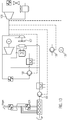
Das erfindungsgemäße Antriebssystem 100 umfasst in dieser Ausführungsform einen Verbrennungsmotor 10 und eine Kühlvorrichtung zum Abführen von Abwärme des Verbrennungsmotors, wobei die Kühlvorrichtung umfasst: einen Luftkühler 20 zum Übertragen von Wärme auf Luft; und eine ORC-Vorrichtung 30 mit einem Arbeitsmedium, einem Verdampfer 31 zum Verdampfen des Arbeitsmediums durch Übertragen von Abwärme des Verbrennungsmotors 10 auf das Arbeitsmedium, einer Expansionsvorrichtung 32 zur Erzeugung von mechanischer Energie (die hier beispielhaft über einen Generator G in elektrische Energie gewandelt wird) und einem Kondensator 33 zum Kondensieren des in der Expansionsvorrichtung 32 expandierten Arbeitsmediums; wobei die Kühlvorrichtung weiterhin einen Kondensator-Kühlfluidkreislauf 40 zum Abführen von Wärme aus dem Kondensator 33 der thermodynamischen Kreisprozessvorrichtung über den Kühler 20 umfasst. Die Kühlvorrichtung umfasst weiterhin einen Verbrennungsmotor-Kühlfluidkreislauf 50, wobei ein erster Zweig 51 des Verbrennungsmotor-Kühlfluidkreislaufs 50 durch den Verdampfer 31 zum Übertragen von Wärme auf das Arbeitsmedium führt. Der Verbrennungsmotor-Kühlfluidkreislauf weist in Strömungsrichtung des Kühlwassers vor dem Verdampfer eine erste Abzweigung 81 in einen zweiten Zweig 52 des Verbrennungsmotor-Kühlfluidkreislaufs 50 zur Umgehung des Verdampfers 31 und eine Zusammenführung 91 des zweiten Zweigs 52 mit dem ersten Zweig 51 nach dem Verdampfer 31 umfasst, wobei der zweite Zweig 52 ein gesteuertes Ventil 71, beispielsweise mit einem Thermostaten, aufweist.The
Hierbei handelt es sich um eine grundlegende Verschaltung, und sie ermöglicht die Nutzung der Energie aus dem Motorkühlwasser. In einem Beispiel wird die Austrittstemperatur des Motorkühlwassers (MKW) über das gesteuerte Ventil (insbesondere Thermostatventil) 71 auf etwa 110 °C gefahren. Standardmäßig ist die MKW-Austrittstemperatur niedriger, im Bereich von 80 °C. Durch die Erhöhung ergibt sich eine höhere Leistung des ORC-Prozesses. In einer alternativen Ausgestaltung, kann statt des Generators G die Einkopplung der Energie auch direkt (mechanisch oder hydraulisch) geschehen, wie bei allen folgenden Verschaltungen auch.This is a basic interconnection, and it allows the use of energy from the engine cooling water. In one example, the outlet temperature of the engine cooling water (MKW) via the controlled valve (in particular thermostatic valve) 71 is driven to about 110 ° C. By default, the MKW outlet temperature is lower, in the range of 80 ° C. The increase results in a higher performance of the ORC process. In an alternative embodiment, instead of the generator G, the coupling of the energy can also be done directly (mechanically or hydraulically), as with all subsequent interconnections.
Hierbei ergibt sich beim Betrieb folgendes Problem: Das System 100 besitzt keine Notlauffähigkeit bei ORC-Ausfall oder nicht ausreichende Wärmeabfuhr. Wenn der ORC-Prozess 30 an der Grenze seiner Wärmeaufnahme ist oder nicht in Betrieb ist, heizt sich der Wasserkreis 50 auf und der Motor 10 überhitzt bzw. wird von einer Motorsteuerung herunter geregelt.The following problem arises during operation: The
Gegenüber der ersten Ausführungsform ist in der zweiten Ausführungsform des Antriebssystems 200 noch eine Einkopplung von Wärme aus dem Abgas des Motors 10 über einen Abgas-Wärmeübertrager 15 in den Verbrennungsmotor-Kühlfluidkreislauf 50 vorgesehen. Der Verbrennungsmotor-Kühlfluidkreislauf 50 enthält in Strömungsrichtung des Kühlfluids vor dem Verdampfer 31 eine zweite Abzweigung 82 in einen dritten Zweig 53 des Verbrennungsmotor-Kühlfluidkreislaufs 50, wobei der dritte Zweig 53 dazu ausgebildet ist, Kühlfluid durch den Kühler 20 und zurück in den ersten Zweig 51 zu führen, wobei die zweite Abzweigung 82 ein zweites Ventil 72, beispielsweise ein Dreiwegeventil 72, umfasst. Wenn die Wärmeübertragungskapazität des Kühlers 20 nicht ausreicht, kann über das zweite Ventil 72 Wasser direkt zum Kühler 20 geführt werden. Der Verbrennungsmotor-Kühlfluidkreislauf 50 weist in Strömungsrichtung des Kühlfluids nach dem Verdampfer 31 eine dritte Abzweigung 83 in einen vierten Zweig 54 des Verbrennungsmotor-Kühlfluidkreislaufs 50 auf, wobei der vierte Zweig 54 Kühlwasser durch den Kühler 20 und zurück in den ersten Zweig 51 führt, wobei die dritte Abzweigung 83 ein drittes Ventil 73, insbesondere ein Dreiwegeventil 73, aufweist, wobei eine Zusammenführung 94 des vierten Zweigs 54 in den dritten Zweig 53 vorgesehen ist. Der Verbrennungsmotor-Kühlfluidkreislauf 50 umfasst in Strömungsrichtung des Kühlfluids vor dem Kühler 20 eine Zusammenführung 95 des dritten bzw. vierten Zweigs 53, 54 mit dem Kondensator-Kühlfluidkreislauf 40 umfasst.In contrast to the first embodiment, in the second embodiment of the
Eine Notlauffähigkeit ist über die 3-Wege-Ventile 72 bzw. 73 gegeben. Beim Betrieb des ORCs sinkt (aufgrund der Zusammenführung 95 des Verbrennungsmotor-Kühlfluidkreislauf 50 und des Kondensator-Kühlfluidkreislaufs 40) die mittlere Temperatur am Eintritt des Kühlers 20, was sich negativ auf die Wärmeübertragungskapazität auswirkt, die von der logarithmischen Temperaturdifferenz zwischen dem Wärmeaufnehmenden und dem Wärmeabführendem Medium bestimmt wird. Wenn die Wärmeübertragungskapazität des Kühlers 20 nicht ausreicht und / oder wenn keine oder eine ungenügende Auskühlung des Motorkühlwassers im Verdampfer 31 stattfindet, dann wird über eines der beiden Ventile 72 oder 73 oder auch durch die Betätigung beider Ventile Motokühlwasser direkt zum Kühler 20 geführt. Dadurch erhöht sich die Temperatur des dem Kühler 20 zugeführten Wassers, die logarithmische Temperaturdifferenz steigt und es wird mehr Wärme übertragen. Nachteilig ist jedoch, dass der ORC ebenso mit relativ heißem Wasser durchströmt wird, was sich negativ auf die elektrische Leistung auswirkt.An emergency running capability is provided via the 3-
Weiterhin kann die Pumpe P3 regelbar ausgeführt werden. Diese kann in Abhängigkeit der Pumpe P4, der Pumpe P5 oder des entsprechenden 3-Wege-Ventils geregelt werden. Ziel dieser Maßnahme ist es, die Wärmeabfuhr des Wärmeübertragers 20 zu verbessern und / oder den Hilfsenergieaufwand für die Pumpen zu minimieren.Furthermore, the pump P3 can be made adjustable. This can be regulated depending on the pump P4, the pump P5 or the corresponding 3-way valve. The aim of this measure is to improve the heat dissipation of the
Wenn nach der Verschaltung in
Wenn nach der Verschaltung in
Hierdurch wird eine kritische Funktion des Verfahrens sichergestellt (Fläche für Hochtemperatur-Kühlung gewährleisten) und eine schnellere und effizientere Regelung erreicht. Die Regelung kann zum Beispiel realisiert werden, indem Kennfelder oder parametrische Tabellen in der Anlagensteuerung hinterlegt werden, die die Drehzahl der Pumpe P3 steuern.This ensures a critical function of the process (ensuring area for high-temperature cooling) and achieves faster and more efficient control. The control can be realized, for example, by maps or parametric tables are stored in the plant control that control the speed of the pump P3.
Im Extremfall, dass die Hochtemperatur-Wärmeabfuhr maximiert werden soll, wird der ORC-Prozess inklusive der Pumpe P3 ausgeschaltet. Um dann zu verhindern, dass ein Teilstrom den Kühler 20 umgeht, kann vor der Pumpe P3 eine Rücklaufsperre vorgesehen werden.In the extreme case that the high-temperature heat dissipation is to be maximized, the ORC process including the pump P3 is switched off. In order to prevent a partial flow from bypassing the cooler 20, a backstop can be provided in front of the pump P3.
Gemäß der dritten Ausführungsform des erfindungsgemäßen Antriebssystems 300 hat der Kühler 20 einen Eingangssammler 21, einen Ausgangssammler 25, und weist dazwischen liegende Kanäle auf, welche jeweils gegenüber liegende Bereiche des Eingangssammlers 21 und des Ausgangssammler 25 miteinander verbinden, wobei ein Eingang 22 des Kondensator-Kühlfluidkreislaufs 40 in den Eingangssammler 21 und ein Eingang 23 des dritten Zweigs 53 des Verbrennungsmotor-Kühlfluidkreislaufs 50 in den Eingangssammler 21 an jeweiligen Endbereichen des Eingangssammlers 21 angeordnet sind, und wobei ein Ausgang 26 des Kondensator-Kühlfluidkreislaufs 40 aus dem Ausgangssammler 25 und ein Ausgang 27 des dritten Zweigs 53 des Verbrennungsmotor-Kühlfluidkreislaufs 50 aus dem Ausgangssammler 25 an jeweiligen Endbereichen des Ausgangssammlers 25 angeordnet sind, wobei der Eingang 22, 23 und Ausgang 26, 27 des Kondensator-Kühlfluidkreislaufs 40 sowie des Verbrennungsmotor-Kühlfluidkreislaufs 50 an jeweils gegenüberliegenden Bereichen des Eingangssammlers 21 bzw. des Ausgangssammlers 25 angeordnet sind.According to the third embodiment of the
Somit erfolgt eine Aufteilung der vorhandenen Kühlerfläche in einen Hochtemperaturbereich (Motorkühlwasser, MKW) und einen Niedertemperaturbereich (Rücklauf zum ORC-Kondensator). In Abhängigkeit des Betriebspunktes kann ein Teil des MKW-Massenstromes durch den ORC 30 geleitet werden und ein Teil direkt gegen Luft gekühlt werden, wie für die zweite Ausführungsform beschrieben wurde. Dadurch gelingt es, die beiden Massenströme zu trennen, und dann kann auf diese Weise dem ORC-Kondensator eine möglichst niedrige Temperatur zur Verfügung gestellt werden und die Abfuhr der überschüssigen Wärme kann auf hohem Temperaturniveau geschehen, was sich positiv auf die Leistung eines Kühlers und auch positiv auf den Hilfsenergiebedarf zur Abfuhr der Wärme an die Umgebung auswirkt.Thus, a division of the existing radiator surface in a high temperature range (engine cooling water, MKW) and a low temperature range (return to the ORC capacitor). Depending on the operating point, a portion of the MKW mass flow may be passed through the
Die dritte Ausführungsform stellt eine Lösung zur Verfügung, um auf möglichst einfache Weise eine Aufteilung der beiden Teilströme auf die Fläche des Kühlers zu realisieren und diese Aufteilung je nach Betriebszustand vorteilhaft einzustellen. Die Anforderungen lauten hierbei, dass die meiste Wärme durch den ORC geleitet wird, um die größtmögliche Effizienzsteigerung des Gesamtsystems zu erzielen. Weiterhin ist es besonders vorteilhaft, die niedrigste Temperatur zur Kühlung des Kondensators zu verwenden um eine höhere Effizienz des ORC Prozesses zu gewährleisten. Zudem müssen geeignete Rücklauftemperaturen für den Motor eingehalten werden. Dies wäre zwar durch baulich bzw. hydraulisch getrennte Kühler zu realisieren, allerdings sind dann die für die jeweiligen Massenströme zur Verfügung stehenden Flächen fest, was jedoch nicht zu unterschiedlichen Lastpunkten passt.The third embodiment provides a solution to realize the simplest possible way a division of the two partial streams on the surface of the radiator and adjust this distribution depending on the operating state advantageous. The The requirements here are that most of the heat is conducted through the ORC in order to maximize the efficiency of the overall system. Furthermore, it is particularly advantageous to use the lowest temperature for cooling the capacitor in order to ensure a higher efficiency of the ORC process. In addition, suitable return temperatures for the engine must be maintained. Although this would be realized by structurally or hydraulically separate cooler, but then available for the respective mass flows areas are fixed, but this does not fit to different load points.
Die Aufteilung des Massenstromes in der Abzweigung 82 bzw. 83 erfolgt mittels des Ventils 72 bzw. 73. Dieses leitet in Abhängigkeit der Temperatur oder eines anderen Kennwerts einen Teilstrom des MKW zum Kühler 20. Dabei ist die Temperaturgrenze abhängig davon, ob die Variante mit Ventil 72 oder 73 vorliegt. Beispielsweise würde das Ventil 72 bei Erreichen einer maximalen Kühlwassertemperatur den Durchfluss in Richtung Kühler 20 schalten und den ORC umgehen. Das Ventil 73 leitet bei Nicht-Erreichen einer geforderten Abkühlung das Kühlwasser in Richtung Kühler 20.The distribution of the mass flow in the
Gemäß der vierten Ausführungsform 400 des erfindungsgemäßen Antriebssystems wird gegenüber der dritten Ausführungsform 300 noch eine weitere Abzweigung vor dem Kühler 20 bereitgestellt, um heißes Kühlfluid über eine Wärmesenke 110 zu führen, um einen Teil der Wärme anderweitig, beispielsweise für Heizzwecke zu nutzen.According to the
In der fünften und sechsten Ausführungsform gemäß
Der ORC Kreislauf ist hier zur Vereinfachung nicht dargestellt, eine Verbindung mit dem ORC-Kreislauf ist in dieser Variante nur angedeutet.The ORC circuit is not shown here for simplicity, a connection with the ORC circuit is only hinted at in this variant.
In der sechsten Ausführung nach
Dadurch ergibt sich zwar ein geringerer maximal zur Verfügung stehender Durchfluss durch den ORC-Kondensator, dies kann jedoch durch die geringere Eintrittstemperatur überkompensiert werden, sodass die Vorteile überwiegen.Although this results in a lower maximum available flow through the ORC capacitor, but this can be overcompensated by the lower inlet temperature, so outweigh the benefits.
Ein weiterer Vorteil ist, dass nur eine Pumpe benötigt wird, um den Kondensator und den Kühler 20 zu durchströmen.Another advantage is that only one pump is needed to flow through the condenser and the
In einigen Betriebszuständen wird nun zur Kühlung des weiteren Kühlkreises nicht die gesamte Fläche des Wärmeübertragers W benötigt. Dann kann man die Flächenreserve des Wärmeübertragers W für die Kühlung des ORC-Kreises nutzen. Dies wird durch die im Folgenden dargestellte Verschaltung in der siebenten Ausführungsform nach
Analog hierzu können ebenfalls weitere Kreise mit weiteren Temperaturen eingebunden werden (z.B. der Kühlkreis für die Klimatisierung im Fahrzeug).Analogously, further circuits with further temperatures can also be integrated (for example, the cooling circuit for the air conditioning in the vehicle).
Auch die Verschaltung nach
Die Funktionsweise der Aufteilung der Massenströme in der dritten und vierten Ausführungsform wird nachfolgend in Zusammenhang mit
Durch die Trennung von Temperaturniveaus wird vorteilhaft die zur Verfügung stehende Wärmeübertragerfläche des Kühlers 20 bestmöglich genutzt. Im Vergleich zur (zuvor beschriebenen) Vermischung der Temperaturen zweier Teilströme können wesentlich geringere Temperaturen auf der kalten Seite erreicht werden. Dies hat Vorteile beim Betrieb eines ORCs aber auch für alle anderen Anwendungen wo zwei Temperaturniveaus über einen Kreislauf zurückgekühlt werden sollen, wie es z.B. bei Stationärmotoren für die Kühlung des Motorkühlwassers und der Ladeluft der Fall ist. Durch die vorgeschlagene Verschaltung kann Wärme bei größtmöglicher Temperaturdifferenz an die Umgebung abgeführt werden, was zu einer Reduktion des Hilfsenergiebedarfs führt, und der niedriger temperierte Volumenstrom wird auf geringere Temperaturen gekühlt als bei einer Vermischung beider Volumenströme. Die Vorrichtung kann wie dargestellt in einem Kühler aber auch durch die Verbindung einer beliebigen Zahl von Kühlern mittels Rohrleitungen bereitgestellt werden.Due to the separation of temperature levels, the available heat exchanger surface of the cooler 20 is advantageously used in the best possible way. Compared to the (previously described) mixing of the temperatures of two partial streams significantly lower temperatures can be achieved on the cold side. This has advantages in the operation of an ORC but also for all other applications where two temperature levels are to be recooled via a circuit, as is the case, for example, with stationary engines for cooling the engine cooling water and the charge air. The proposed interconnection can heat at the highest possible Temperature difference are dissipated to the environment, resulting in a reduction of the auxiliary energy demand, and the lower-temperature flow rate is cooled to lower temperatures than when mixing the two volume flows. The device can be provided as shown in a cooler but also by the connection of any number of coolers by means of pipelines.
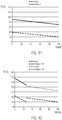
Die
Bei der Verwendung von zwei Temperaturstufen, wie in
Es ist hier bemerkt, dass die beschriebenen Temperatur- und Leistungswerte nur beispielhaft zu sehen sind, durch eine Optimierung und Anpassung von Temperaturgrenzen kann noch weiteres Potenzial gehoben werden. Eine Optimierung berücksichtigt neben der Temperatur auch den Einfluss des Massenstroms auf die Wärmeübertragungskapazität / Leistung eines Wärmeübertragers.It is noted here that the described temperature and power values can only be seen by way of example; by optimizing and adapting temperature limits, even further potential can be raised. An optimization takes into account the temperature as well as the influence of the mass flow on the heat transfer capacity / performance of a heat exchanger.
Das Antriebssystem lässt sich in Hinblick auf weitere Synergien weiterentwickeln, die im Zusammenhang mit
Die dargestellten Ausführungsformen sind lediglich beispielhaft und der vollständige Umfang der vorliegenden Erfindung wird durch die Ansprüche definiert.The illustrated embodiments are merely exemplary and the full scope of the present invention is defined by the claims.
Claims (14)
- System for heat utilization, comprising:a heat source (10); anda cooling device for discharging heat from the heat source;wherein the cooling device comprises:a heat exchanger / radiator (20) for transferring heat to a surrounding medium, wherein in particular the radiator is an air cooler and the surrounding medium is air; anda thermodynamic cycle device (30), in particular an ORC device, having a working medium, an evaporator (31) for evaporating the working medium by transferring heat of the heat source (10) to the working medium, an expansion device (32) for generating mechanical energy, and a condenser (33) for condensing the working medium expanded in the expansion device (32);wherein the cooling device comprises a condenser coolant circuit (40) for discharging heat from the condenser (33) of the thermodynamic cycle device (30) via the heat exchanger / radiator (20); andwherein the cooling device further comprises a heat source coolant circuit (50), wherein a first branch (51) of the heat source coolant circuit passes through the evaporator (31) for transferring heat to the working fluid;characterized in thatthe heat source coolant circuit in the flow direction of a cooling fluid upstream of the evaporator comprises a first branch-off (81) into a second branch (52) of the heat source coolant circuit (50) for bypassing the evaporator (31) and a merging (91) of the second branch (52) with the first branch (51) downstream of the evaporator (31), the second branch (52) comprising a first valve (71), preferably a controlled valve.
- System according to claim 1, wherein the heat source comprises a power process device, in particular an internal combustion engine (10), a gas turbine or a Stirling engine, a boiler, in particular a biomass burner, or a fuel cell.
- System according to claim 1 or 2, wherein in the heat source coolant circuit, a first pump (P1) and / or in the thermodynamic cycle device, a second pump (P2) for pumping the working medium and / or in the condenser coolant circuit, a third pump (P3) is provided.
- System according to any one of claims 1 to 3, wherein the heat source coolant circuit in the flow direction of the cooling fluid upstream of the evaporator comprises a second branch-off (82) into a third branch (53) of the heat source coolant circuit, and wherein the third branch is configured to move cooling fluid through the heat exchanger / radiator and back into the first branch, wherein the second branch-off preferably comprises a second valve (72), in particular a three-way valve, or wherein the third branch preferably comprises a fourth pump (P4).
- System according to any one of claims 1 to 4, wherein the heat source coolant circuit comprises, in the flow direction of the cooling fluid downstream of the evaporator, a third branch-off (83) into a fourth branch (54) of the heat source coolant circuit, and wherein the fourth branch is configured to move cooling fluid through the heat exchanger / radiator and back into the first branch, wherein the third branch preferably comprises a third valve (73), in particular a three-way valve, or wherein the fourth branch preferably comprises a fifth pump (P5), wherein in combination with claim 4, a merging of the fourth branch into the third branch is provided.
- System of claim 4 or 5, wherein the heat source coolant circuit in the flow direction of the cooling fluid upstream the heat exchanger / radiator comprises a merging (95) of the third and/or fourth branch with the condenser coolant circuit.
- System of claim 4 or 5, wherein the heat exchanger / radiator has an inlet collector (21), an outlet collector 25), and intermediate channels interconnecting respective opposite portions of the inlet collector and the outlet collector, and wherein an inlet (22) of the condenser cooling fluid cycle into the inlet collector and an inlet (23) of the third and/or fourth branch of the heat source coolant circuit into the inlet collector are spaced from each other, in particular at respective end portions of the inlet collector, and wherein an outlet (26) of the condenser coolant circuit from the outlet collector and an outlet (27) of the third and/or fourth branch of the heat source coolant circuit from the outlet collector are spaced from each other, in particular arranged at respective end portions of the outlet collector, wherein the inlet (22, 23) and outlet (26, 27) of the condenser coolant circuit and the heat source coolant circuit are each arranged at respective opposite areas of the inlet collector and the outlet collector.
- System according to any one of claims 1 to 7, wherein the cooling device further comprises at least one heat exchanger (15) for transferring heat in exhaust gas of the heat source to the heat source coolant circuit.
- System according to any one of claims 1 to 8, further comprising a generator (G), by means of which the mechanical energy generated by the expansion device is convertible into electrical energy.
- System according to any one of claims 1 to 9, wherein by the energy generated by the expansion device (32) mechanical energy can be used via a respective electrical, mechanical or hydraulic coupling for(a) driving a fan of the condenser (30) and / or a fan of the heat exchanger / radiator; and / or(b) driving a circulation pump (101) in the heat source coolant circuit and / or a feed pump (102) of the thermodynamic cycle device and / or a circulation pump (103) in the condenser coolant circuit and / or a water pump and / or a hydraulic pump and / or an oil pump; and or(c) driving a generator (105) and / or a starter of the drive system; and / or(d) driving a refrigeration compressor (106) of an air conditioner; and / or(e) coupling the mechanical energy generated by the expansion device in a drive train of the heat source, in particular directly to a drive shaft, wherein the heat source comprises a power process device, in particular an internal combustion engine.
- System according to any one of claims 1 to 10, wherein a partial flow of the vaporized working medium is usable to drive a fan of the condenser and / or a fan (107) of the heat exchanger / radiator and / or a refrigeration compressor; and / or
wherein heat from condensed working medium and / or from the heat source coolant circuit for feeding into a heating device can be coupled out. - System according to any one of claims 1 to 11, further comprising: a further cooling circuit with a further heat exchanger, wherein the further heat exchanger is connected in series with or parallel to the heat exchanger / radiator.
- Method for discharging heat from a heat source by means of a cooling device,
wherein the cooling device comprises a heat exchanger / radiator, a thermodynamic cycle device, in particular an ORC device, with a working medium, an evaporator, an expansion device and a condenser and a condenser coolant circuit, and wherein the method comprises the following steps:transferring heat to an surrounding medium with the heat exchanger / radiator, wherein in particular the radiator is an air cooler and the surrounding medium is air;vaporizing the working medium with the evaporator by transferring heat from the heat source to the working medium;generating mechanical energy by means of the expansion device;condensing the working medium expanded in the expansion device by means of the condenser;discharging heat from the condenser of the thermodynamic cycle device via the heat exchanger / radiator; andpassing a first branch of a heat source coolant circuit through the evaporator to transfer heat to the working fluid;characterized byfirst branching-off of a cooling fluid in the heat source coolant circuit in the flow direction upstream the evaporator into a second branch of the heat source coolant circuit for bypassing the evaporator and merging the second branch with the first branch downstream the evaporator. - Method of claim 13, further comprising the steps of:second branching-off of the cooling fluid upstream of the evaporator into a third branch of the heat source coolant circuit, the third branch passing cooling fluid through the heat exchanger / radiator and back into the first branch; and orthird branching-off of the cooling fluid downstream of the evaporator into a fourth branch of the heat source coolant circuit, the fourth branch passing cooling fluid through the heat exchanger / radiator and back into the first branch;wherein the heat exchanger / radiator has an inlet collector, an outlet collector, and intermediate channels interconnecting respective opposite portions of the inlet collector and the outlet collector, and wherein an inlet of the condenser cooling fluid cycle into the inlet collector and an inlet of the third and/or fourth branches of the heat source coolant circuit into the inlet collector are spaced from each other, in particular at respective end portions of the inlet collector, and wherein an outlet of the condenser coolant circuit from the outlet collector and an outlet of the third and/or fourth branch of the heat source coolant circuit from the outlet collector, respectively, are spaced from each other, in particular arranged at respective end portions of the outlet collector, wherein the inlet and outlet of the condenser coolant circuit and of the heat source coolant circuit are arranged at respective opposite portions of the inlet and the outlet collector.
Priority Applications (4)
| Application Number | Priority Date | Filing Date | Title |
|---|---|---|---|
| CN201680075472.0A CN108431376B (en) | 2015-10-21 | 2016-10-06 | Functional synergy of thermodynamic cycle and heat source |
| US15/767,930 US10577984B2 (en) | 2015-10-21 | 2016-10-06 | Functional synergies of thermodynamic cycles and heat sources |
| PCT/EP2016/073846 WO2017067790A1 (en) | 2015-10-21 | 2016-10-06 | Functional synergies of thermodynamic cycles and heat sources |
| BR112018007922-7A BR112018007922B1 (en) | 2015-10-21 | 2016-10-06 | HEAT UTILIZATION SYSTEM, AND METHOD OF DISCHARGING HEAT FROM A HEAT SOURCE BY MEANS OF A COOLING DEVICE |
Applications Claiming Priority (1)
| Application Number | Priority Date | Filing Date | Title |
|---|---|---|---|
| EP15190780.5A EP3159506B1 (en) | 2015-10-21 | 2015-10-21 | Functional synergies in the integration of orc systems in combustion engines |
Publications (2)
| Publication Number | Publication Date |
|---|---|
| EP3163036A1 EP3163036A1 (en) | 2017-05-03 |
| EP3163036B1 true EP3163036B1 (en) | 2018-09-26 |
Family
ID=54337688
Family Applications (2)
| Application Number | Title | Priority Date | Filing Date |
|---|---|---|---|
| EP15190780.5A Active EP3159506B1 (en) | 2015-10-21 | 2015-10-21 | Functional synergies in the integration of orc systems in combustion engines |
| EP16191660.6A Active EP3163036B1 (en) | 2015-10-21 | 2016-09-30 | Functional synergies of thermodynamic circuit processes and heat sources |
Family Applications Before (1)
| Application Number | Title | Priority Date | Filing Date |
|---|---|---|---|
| EP15190780.5A Active EP3159506B1 (en) | 2015-10-21 | 2015-10-21 | Functional synergies in the integration of orc systems in combustion engines |
Country Status (4)
| Country | Link |
|---|---|
| US (1) | US10577984B2 (en) |
| EP (2) | EP3159506B1 (en) |
| CN (1) | CN108431376B (en) |
| WO (1) | WO2017067790A1 (en) |
Families Citing this family (9)
| Publication number | Priority date | Publication date | Assignee | Title |
|---|---|---|---|---|
| DK3530890T3 (en) * | 2018-02-27 | 2023-01-16 | Orcan Energy Ag | Drive with integrated ORC |
| JP7099392B2 (en) * | 2019-04-03 | 2022-07-12 | トヨタ自動車株式会社 | In-vehicle temperature control device |
| SE543339C2 (en) | 2019-04-11 | 2020-12-08 | Scania Cv Ab | Waste Heat Recovery System, Powertrain, and Vehicle |
| WO2020213773A1 (en) * | 2019-04-17 | 2020-10-22 | 비아이피 주식회사 | Ship power generation system using organic rankine cycle having improved power generation efficiency |
| SE543454C2 (en) * | 2019-06-13 | 2021-02-23 | Scania Cv Ab | Thermal Management System, Method of Cooling a Condenser of a Waste Heat Recovery System, and Related Devices |
| CN111810268A (en) * | 2020-08-11 | 2020-10-23 | 四川大学 | Hot end constant temperature heat conduction type waste heat power generation device |
| FR3121554B1 (en) | 2021-03-31 | 2023-03-03 | Ifp Energies Now | Fuel cell cooling system and method |
| CN113107622B (en) * | 2021-04-27 | 2022-07-12 | 中国能源建设集团广东省电力设计研究院有限公司 | Efficient Brayton-Rankine cycle flexible power generation system |
| CN115013220B (en) * | 2022-06-30 | 2023-10-13 | 中国电建集团华东勘测设计研究院有限公司 | Compact geothermal energy compressed air energy storage system and method based on medium-deep dry-hot rock |
Family Cites Families (12)
| Publication number | Priority date | Publication date | Assignee | Title |
|---|---|---|---|---|
| WO2008106774A1 (en) * | 2007-03-02 | 2008-09-12 | Victor Juchymenko | Controlled organic rankine cycle system for recovery and conversion of thermal energy |
| WO2009133620A1 (en) * | 2008-05-01 | 2009-11-05 | サンデン株式会社 | Waste heat utilization device for internal combustion |
| US20100326076A1 (en) * | 2009-06-30 | 2010-12-30 | General Electric Company | Optimized system for recovering waste heat |
| DE102010003906A1 (en) * | 2010-04-13 | 2011-10-13 | Behr Gmbh & Co. Kg | internal combustion engine |
| SE1150169A1 (en) * | 2011-02-25 | 2012-06-26 | Scania Cv Ab | Systems for converting thermal energy into mechanical energy in a vehicle |
| JP5621721B2 (en) * | 2011-06-30 | 2014-11-12 | 株式会社豊田自動織機 | Rankine cycle |
| KR20150036784A (en) | 2012-08-03 | 2015-04-07 | 트리-오-겐 그룹 비.브이. | System for recovering through an organic rankine cycle (orc) energy from a plurality of heat sources |
| DE102012021327A1 (en) * | 2012-10-26 | 2014-01-23 | Voith Patent Gmbh | Oil or gas conveying system of oil or gas production system for use in oil industry, has quick-closing valve that is provided in upstream of expansion machine, such that medium flow path is shut off in pulsed manner |
| DE102012022648A1 (en) * | 2012-11-20 | 2014-05-22 | Daimler Ag | Device for lubrication of e.g. expansion device in working medium circuit of motor vehicle, has electrodes that are coupled with control device such that electrode voltage is adjusted and is generated in lubricating film between electrodes |
| EP3192986B1 (en) * | 2013-04-08 | 2019-10-09 | FPT Motorenforschung AG | Turbo-compound system |
| DE102013011519A1 (en) | 2013-07-09 | 2015-01-15 | Volkswagen Ag | Heat exchange device and drive unit for a motor vehicle |
| DE102014206026A1 (en) * | 2014-03-31 | 2015-10-01 | Mtu Friedrichshafen Gmbh | Cooling device for a condenser of a system for a thermodynamic cycle, system for a thermodynamic cycle, arrangement with an internal combustion engine and a system, motor vehicle, and a method for performing a thermodynamic cycle |
-
2015
- 2015-10-21 EP EP15190780.5A patent/EP3159506B1/en active Active
-
2016
- 2016-09-30 EP EP16191660.6A patent/EP3163036B1/en active Active
- 2016-10-06 WO PCT/EP2016/073846 patent/WO2017067790A1/en active Application Filing
- 2016-10-06 CN CN201680075472.0A patent/CN108431376B/en active Active
- 2016-10-06 US US15/767,930 patent/US10577984B2/en active Active
Non-Patent Citations (1)
| Title |
|---|
| None * |
Also Published As
| Publication number | Publication date |
|---|---|
| US20180313234A1 (en) | 2018-11-01 |
| BR112018007922A2 (en) | 2018-10-30 |
| EP3159506A1 (en) | 2017-04-26 |
| CN108431376B (en) | 2020-06-16 |
| EP3159506B1 (en) | 2020-08-19 |
| US10577984B2 (en) | 2020-03-03 |
| CN108431376A (en) | 2018-08-21 |
| EP3163036A1 (en) | 2017-05-03 |
| WO2017067790A1 (en) | 2017-04-27 |
Similar Documents
| Publication | Publication Date | Title |
|---|---|---|
| EP3163036B1 (en) | Functional synergies of thermodynamic circuit processes and heat sources | |
| EP3454401B1 (en) | Motor vehicle with a cooling system | |
| EP1925806B1 (en) | System with an organic Rankine cycle for operating at least one expansion machine, heat exchanger for operating one expansion machine, method for operating at least one expansion machine | |
| WO2019096696A1 (en) | Cooling system for a motor vehicle and motor vehicle having such a cooling system | |
| DE102016006682B4 (en) | Method for operating an air conditioning system of an electric or hybrid vehicle and air conditioning system for carrying out the method | |
| DE102006010247A1 (en) | Drive unit with heat recovery | |
| EP1111214A2 (en) | Circuit for cooling and heating with two heat exchangers | |
| EP3918199B1 (en) | Cooling arrangement and method for cooling a compressed-air generator with at least two stages | |
| DE102007057164A1 (en) | Expansion machine e.g. scroll expander, driving system, has organic rankine-cylce including two preheat exchanger stages, where cooling agent flows through two preheat exchanger stages | |
| EP2274508A1 (en) | Exhaust gas system for an internal combustion engine | |
| DE102008064015A1 (en) | Waste heat recovery device for utilization of waste heat of internal combustion engine of motor vehicle, has working fluid circuit connected with coolant heat exchanger, and coolant circuit fluid coupled with engine cooling circuit | |
| EP2423482B1 (en) | Cooling system for a vehicle | |
| DE102007026869B4 (en) | Cooling device for a liquid-cooled internal combustion engine of a motor vehicle and method for operating such a cooling device | |
| DE102011085961A1 (en) | Cooling circuit | |
| DE102009050263A1 (en) | Heat recovery system for recovering heat from Clausius-Rankine processes in motor vehicle, has Rankine-cycle with working medium, and exhaust system thermally connected to Rankine-cycle by heat exchangers | |
| DE102007061032B4 (en) | Assembly for energy recovery in an internal combustion engine | |
| DE102016218764A1 (en) | Internal combustion engine of a motor vehicle with a waste heat utilization device | |
| EP3023622B1 (en) | Cooling system for a vehicle, in particular a commercial vehicle | |
| EP3530890B1 (en) | Drive with integrated orc | |
| EP3559564B1 (en) | Method and apparatus for generating process cold and process steam | |
| DE102013021394A1 (en) | Waste heat recovery arrangement used for utilizing waste heat of e.g. diesel engine, has working medium circuit that is provided with an air-cooled condenser, and heat exchanger whose output side is connected to downstream of expander | |
| EP2449228A2 (en) | Method for operating a power plant using a gas turbine system | |
| DE102017011851A1 (en) | Arrangement for converting thermal energy from heat loss of an internal combustion engine | |
| DE102019008230B4 (en) | Cooling system for an internal combustion engine, electric drive and exhaust heat recovery system in a hybrid electric powertrain and vehicle equipped therewith | |
| EP3951140B1 (en) | Energy recovery device with heat recovery circuit |
Legal Events
| Date | Code | Title | Description |
|---|---|---|---|
| PUAI | Public reference made under article 153(3) epc to a published international application that has entered the european phase |
Free format text: ORIGINAL CODE: 0009012 |
|
| AK | Designated contracting states |
Kind code of ref document: A1 Designated state(s): AL AT BE BG CH CY CZ DE DK EE ES FI FR GB GR HR HU IE IS IT LI LT LU LV MC MK MT NL NO PL PT RO RS SE SI SK SM TR |
|
| AX | Request for extension of the european patent |
Extension state: BA ME |
|
| 17P | Request for examination filed |
Effective date: 20170914 |
|
| RBV | Designated contracting states (corrected) |
Designated state(s): AL AT BE BG CH CY CZ DE DK EE ES FI FR GB GR HR HU IE IS IT LI LT LU LV MC MK MT NL NO PL PT RO RS SE SI SK SM TR |
|
| GRAP | Despatch of communication of intention to grant a patent |
Free format text: ORIGINAL CODE: EPIDOSNIGR1 |
|
| RIC1 | Information provided on ipc code assigned before grant |
Ipc: F01K 15/02 20060101ALI20180312BHEP Ipc: F01K 23/06 20060101AFI20180312BHEP |
|
| INTG | Intention to grant announced |
Effective date: 20180405 |
|
| GRAS | Grant fee paid |
Free format text: ORIGINAL CODE: EPIDOSNIGR3 |
|
| GRAA | (expected) grant |
Free format text: ORIGINAL CODE: 0009210 |
|
| AK | Designated contracting states |
Kind code of ref document: B1 Designated state(s): AL AT BE BG CH CY CZ DE DK EE ES FI FR GB GR HR HU IE IS IT LI LT LU LV MC MK MT NL NO PL PT RO RS SE SI SK SM TR |
|
| REG | Reference to a national code |
Ref country code: GB Ref legal event code: FG4D Free format text: NOT ENGLISH |
|
| REG | Reference to a national code |
Ref country code: CH Ref legal event code: EP |
|
| REG | Reference to a national code |
Ref country code: AT Ref legal event code: REF Ref document number: 1046277 Country of ref document: AT Kind code of ref document: T Effective date: 20181015 |
|
| REG | Reference to a national code |
Ref country code: IE Ref legal event code: FG4D Free format text: LANGUAGE OF EP DOCUMENT: GERMAN |
|
| REG | Reference to a national code |
Ref country code: DE Ref legal event code: R096 Ref document number: 502016002079 Country of ref document: DE |
|
| REG | Reference to a national code |
Ref country code: FR Ref legal event code: PLFP Year of fee payment: 3 |
|
| REG | Reference to a national code |
Ref country code: CH Ref legal event code: NV Representative=s name: BOVARD AG PATENT- UND MARKENANWAELTE, CH |
|
| REG | Reference to a national code |
Ref country code: NL Ref legal event code: FP |
|
| REG | Reference to a national code |
Ref country code: SE Ref legal event code: TRGR |
|
| PG25 | Lapsed in a contracting state [announced via postgrant information from national office to epo] |
Ref country code: NO Free format text: LAPSE BECAUSE OF FAILURE TO SUBMIT A TRANSLATION OF THE DESCRIPTION OR TO PAY THE FEE WITHIN THE PRESCRIBED TIME-LIMIT Effective date: 20181226 Ref country code: RS Free format text: LAPSE BECAUSE OF FAILURE TO SUBMIT A TRANSLATION OF THE DESCRIPTION OR TO PAY THE FEE WITHIN THE PRESCRIBED TIME-LIMIT Effective date: 20180926 Ref country code: FI Free format text: LAPSE BECAUSE OF FAILURE TO SUBMIT A TRANSLATION OF THE DESCRIPTION OR TO PAY THE FEE WITHIN THE PRESCRIBED TIME-LIMIT Effective date: 20180926 Ref country code: GR Free format text: LAPSE BECAUSE OF FAILURE TO SUBMIT A TRANSLATION OF THE DESCRIPTION OR TO PAY THE FEE WITHIN THE PRESCRIBED TIME-LIMIT Effective date: 20181227 Ref country code: BG Free format text: LAPSE BECAUSE OF FAILURE TO SUBMIT A TRANSLATION OF THE DESCRIPTION OR TO PAY THE FEE WITHIN THE PRESCRIBED TIME-LIMIT Effective date: 20181226 Ref country code: LT Free format text: LAPSE BECAUSE OF FAILURE TO SUBMIT A TRANSLATION OF THE DESCRIPTION OR TO PAY THE FEE WITHIN THE PRESCRIBED TIME-LIMIT Effective date: 20180926 |
|
| REG | Reference to a national code |
Ref country code: LT Ref legal event code: MG4D |
|
| PG25 | Lapsed in a contracting state [announced via postgrant information from national office to epo] |
Ref country code: AL Free format text: LAPSE BECAUSE OF FAILURE TO SUBMIT A TRANSLATION OF THE DESCRIPTION OR TO PAY THE FEE WITHIN THE PRESCRIBED TIME-LIMIT Effective date: 20180926 Ref country code: LV Free format text: LAPSE BECAUSE OF FAILURE TO SUBMIT A TRANSLATION OF THE DESCRIPTION OR TO PAY THE FEE WITHIN THE PRESCRIBED TIME-LIMIT Effective date: 20180926 Ref country code: HR Free format text: LAPSE BECAUSE OF FAILURE TO SUBMIT A TRANSLATION OF THE DESCRIPTION OR TO PAY THE FEE WITHIN THE PRESCRIBED TIME-LIMIT Effective date: 20180926 |
|
| PG25 | Lapsed in a contracting state [announced via postgrant information from national office to epo] |
Ref country code: PL Free format text: LAPSE BECAUSE OF FAILURE TO SUBMIT A TRANSLATION OF THE DESCRIPTION OR TO PAY THE FEE WITHIN THE PRESCRIBED TIME-LIMIT Effective date: 20180926 Ref country code: EE Free format text: LAPSE BECAUSE OF FAILURE TO SUBMIT A TRANSLATION OF THE DESCRIPTION OR TO PAY THE FEE WITHIN THE PRESCRIBED TIME-LIMIT Effective date: 20180926 Ref country code: ES Free format text: LAPSE BECAUSE OF FAILURE TO SUBMIT A TRANSLATION OF THE DESCRIPTION OR TO PAY THE FEE WITHIN THE PRESCRIBED TIME-LIMIT Effective date: 20180926 Ref country code: IS Free format text: LAPSE BECAUSE OF FAILURE TO SUBMIT A TRANSLATION OF THE DESCRIPTION OR TO PAY THE FEE WITHIN THE PRESCRIBED TIME-LIMIT Effective date: 20190126 Ref country code: CZ Free format text: LAPSE BECAUSE OF FAILURE TO SUBMIT A TRANSLATION OF THE DESCRIPTION OR TO PAY THE FEE WITHIN THE PRESCRIBED TIME-LIMIT Effective date: 20180926 Ref country code: RO Free format text: LAPSE BECAUSE OF FAILURE TO SUBMIT A TRANSLATION OF THE DESCRIPTION OR TO PAY THE FEE WITHIN THE PRESCRIBED TIME-LIMIT Effective date: 20180926 |
|
| PG25 | Lapsed in a contracting state [announced via postgrant information from national office to epo] |
Ref country code: SM Free format text: LAPSE BECAUSE OF FAILURE TO SUBMIT A TRANSLATION OF THE DESCRIPTION OR TO PAY THE FEE WITHIN THE PRESCRIBED TIME-LIMIT Effective date: 20180926 Ref country code: PT Free format text: LAPSE BECAUSE OF FAILURE TO SUBMIT A TRANSLATION OF THE DESCRIPTION OR TO PAY THE FEE WITHIN THE PRESCRIBED TIME-LIMIT Effective date: 20190126 Ref country code: SK Free format text: LAPSE BECAUSE OF FAILURE TO SUBMIT A TRANSLATION OF THE DESCRIPTION OR TO PAY THE FEE WITHIN THE PRESCRIBED TIME-LIMIT Effective date: 20180926 |
|
| REG | Reference to a national code |
Ref country code: IE Ref legal event code: MM4A |
|
| REG | Reference to a national code |
Ref country code: DE Ref legal event code: R097 Ref document number: 502016002079 Country of ref document: DE |
|
| PG25 | Lapsed in a contracting state [announced via postgrant information from national office to epo] |
Ref country code: LU Free format text: LAPSE BECAUSE OF NON-PAYMENT OF DUE FEES Effective date: 20180930 |
|
| PG25 | Lapsed in a contracting state [announced via postgrant information from national office to epo] |
Ref country code: DK Free format text: LAPSE BECAUSE OF FAILURE TO SUBMIT A TRANSLATION OF THE DESCRIPTION OR TO PAY THE FEE WITHIN THE PRESCRIBED TIME-LIMIT Effective date: 20180926 Ref country code: IE Free format text: LAPSE BECAUSE OF NON-PAYMENT OF DUE FEES Effective date: 20180930 Ref country code: MC Free format text: LAPSE BECAUSE OF FAILURE TO SUBMIT A TRANSLATION OF THE DESCRIPTION OR TO PAY THE FEE WITHIN THE PRESCRIBED TIME-LIMIT Effective date: 20180926 |
|
| PLBE | No opposition filed within time limit |
Free format text: ORIGINAL CODE: 0009261 |
|
| STAA | Information on the status of an ep patent application or granted ep patent |
Free format text: STATUS: NO OPPOSITION FILED WITHIN TIME LIMIT |
|
| 26N | No opposition filed |
Effective date: 20190627 |
|
| PG25 | Lapsed in a contracting state [announced via postgrant information from national office to epo] |
Ref country code: SI Free format text: LAPSE BECAUSE OF FAILURE TO SUBMIT A TRANSLATION OF THE DESCRIPTION OR TO PAY THE FEE WITHIN THE PRESCRIBED TIME-LIMIT Effective date: 20180926 |
|
| PG25 | Lapsed in a contracting state [announced via postgrant information from national office to epo] |
Ref country code: MT Free format text: LAPSE BECAUSE OF FAILURE TO SUBMIT A TRANSLATION OF THE DESCRIPTION OR TO PAY THE FEE WITHIN THE PRESCRIBED TIME-LIMIT Effective date: 20180926 |
|
| PG25 | Lapsed in a contracting state [announced via postgrant information from national office to epo] |
Ref country code: TR Free format text: LAPSE BECAUSE OF FAILURE TO SUBMIT A TRANSLATION OF THE DESCRIPTION OR TO PAY THE FEE WITHIN THE PRESCRIBED TIME-LIMIT Effective date: 20180926 |
|
| PG25 | Lapsed in a contracting state [announced via postgrant information from national office to epo] |
Ref country code: CY Free format text: LAPSE BECAUSE OF FAILURE TO SUBMIT A TRANSLATION OF THE DESCRIPTION OR TO PAY THE FEE WITHIN THE PRESCRIBED TIME-LIMIT Effective date: 20180926 Ref country code: MK Free format text: LAPSE BECAUSE OF NON-PAYMENT OF DUE FEES Effective date: 20180926 Ref country code: HU Free format text: LAPSE BECAUSE OF FAILURE TO SUBMIT A TRANSLATION OF THE DESCRIPTION OR TO PAY THE FEE WITHIN THE PRESCRIBED TIME-LIMIT; INVALID AB INITIO Effective date: 20160930 |
|
| REG | Reference to a national code |
Ref country code: AT Ref legal event code: MM01 Ref document number: 1046277 Country of ref document: AT Kind code of ref document: T Effective date: 20210930 |
|
| PG25 | Lapsed in a contracting state [announced via postgrant information from national office to epo] |
Ref country code: AT Free format text: LAPSE BECAUSE OF NON-PAYMENT OF DUE FEES Effective date: 20210930 |
|
| PGFP | Annual fee paid to national office [announced via postgrant information from national office to epo] |
Ref country code: NL Payment date: 20230921 Year of fee payment: 8 Ref country code: GB Payment date: 20230920 Year of fee payment: 8 |
|
| PGFP | Annual fee paid to national office [announced via postgrant information from national office to epo] |
Ref country code: SE Payment date: 20230921 Year of fee payment: 8 Ref country code: FR Payment date: 20230922 Year of fee payment: 8 Ref country code: DE Payment date: 20230926 Year of fee payment: 8 Ref country code: BE Payment date: 20230920 Year of fee payment: 8 |
|
| PGFP | Annual fee paid to national office [announced via postgrant information from national office to epo] |
Ref country code: IT Payment date: 20230927 Year of fee payment: 8 Ref country code: CH Payment date: 20231001 Year of fee payment: 8 |