EP3163031A1 - Cranked shaft with cranks to control a variable vane assembly - Google Patents
Cranked shaft with cranks to control a variable vane assembly Download PDFInfo
- Publication number
- EP3163031A1 EP3163031A1 EP16193792.5A EP16193792A EP3163031A1 EP 3163031 A1 EP3163031 A1 EP 3163031A1 EP 16193792 A EP16193792 A EP 16193792A EP 3163031 A1 EP3163031 A1 EP 3163031A1
- Authority
- EP
- European Patent Office
- Prior art keywords
- elongate shaft
- attachment devices
- shaft assembly
- shaft body
- longitudinal axis
- Prior art date
- Legal status (The legal status is an assumption and is not a legal conclusion. Google has not performed a legal analysis and makes no representation as to the accuracy of the status listed.)
- Withdrawn
Links
- 239000000463 material Substances 0.000 description 9
- 238000003466 welding Methods 0.000 description 5
- 238000000034 method Methods 0.000 description 3
- 238000006073 displacement reaction Methods 0.000 description 2
- 238000005304 joining Methods 0.000 description 2
- 238000004519 manufacturing process Methods 0.000 description 2
- 238000012986 modification Methods 0.000 description 2
- 230000004048 modification Effects 0.000 description 2
- 239000007787 solid Substances 0.000 description 2
- 229910001116 A514 steel Inorganic materials 0.000 description 1
- 229910000975 Carbon steel Inorganic materials 0.000 description 1
- 229910000831 Steel Inorganic materials 0.000 description 1
- 238000003491 array Methods 0.000 description 1
- 238000005219 brazing Methods 0.000 description 1
- 239000010962 carbon steel Substances 0.000 description 1
- 239000011248 coating agent Substances 0.000 description 1
- 238000000576 coating method Methods 0.000 description 1
- 230000003247 decreasing effect Effects 0.000 description 1
- JEIPFZHSYJVQDO-UHFFFAOYSA-N iron(III) oxide Inorganic materials O=[Fe]O[Fe]=O JEIPFZHSYJVQDO-UHFFFAOYSA-N 0.000 description 1
- 239000010959 steel Substances 0.000 description 1
Images

Classifications
-
- F—MECHANICAL ENGINEERING; LIGHTING; HEATING; WEAPONS; BLASTING
- F16—ENGINEERING ELEMENTS AND UNITS; GENERAL MEASURES FOR PRODUCING AND MAINTAINING EFFECTIVE FUNCTIONING OF MACHINES OR INSTALLATIONS; THERMAL INSULATION IN GENERAL
- F16C—SHAFTS; FLEXIBLE SHAFTS; ELEMENTS OR CRANKSHAFT MECHANISMS; ROTARY BODIES OTHER THAN GEARING ELEMENTS; BEARINGS
- F16C3/00—Shafts; Axles; Cranks; Eccentrics
- F16C3/04—Crankshafts, eccentric-shafts; Cranks, eccentrics
- F16C3/18—Eccentric-shafts
-
- F—MECHANICAL ENGINEERING; LIGHTING; HEATING; WEAPONS; BLASTING
- F16—ENGINEERING ELEMENTS AND UNITS; GENERAL MEASURES FOR PRODUCING AND MAINTAINING EFFECTIVE FUNCTIONING OF MACHINES OR INSTALLATIONS; THERMAL INSULATION IN GENERAL
- F16C—SHAFTS; FLEXIBLE SHAFTS; ELEMENTS OR CRANKSHAFT MECHANISMS; ROTARY BODIES OTHER THAN GEARING ELEMENTS; BEARINGS
- F16C3/00—Shafts; Axles; Cranks; Eccentrics
- F16C3/02—Shafts; Axles
-
- F—MECHANICAL ENGINEERING; LIGHTING; HEATING; WEAPONS; BLASTING
- F16—ENGINEERING ELEMENTS AND UNITS; GENERAL MEASURES FOR PRODUCING AND MAINTAINING EFFECTIVE FUNCTIONING OF MACHINES OR INSTALLATIONS; THERMAL INSULATION IN GENERAL
- F16C—SHAFTS; FLEXIBLE SHAFTS; ELEMENTS OR CRANKSHAFT MECHANISMS; ROTARY BODIES OTHER THAN GEARING ELEMENTS; BEARINGS
- F16C3/00—Shafts; Axles; Cranks; Eccentrics
- F16C3/04—Crankshafts, eccentric-shafts; Cranks, eccentrics
- F16C3/06—Crankshafts
- F16C3/10—Crankshafts assembled of several parts, e.g. by welding by crimping
-
- F—MECHANICAL ENGINEERING; LIGHTING; HEATING; WEAPONS; BLASTING
- F01—MACHINES OR ENGINES IN GENERAL; ENGINE PLANTS IN GENERAL; STEAM ENGINES
- F01D—NON-POSITIVE DISPLACEMENT MACHINES OR ENGINES, e.g. STEAM TURBINES
- F01D17/00—Regulating or controlling by varying flow
- F01D17/10—Final actuators
- F01D17/12—Final actuators arranged in stator parts
- F01D17/14—Final actuators arranged in stator parts varying effective cross-sectional area of nozzles or guide conduits
- F01D17/16—Final actuators arranged in stator parts varying effective cross-sectional area of nozzles or guide conduits by means of nozzle vanes
- F01D17/162—Final actuators arranged in stator parts varying effective cross-sectional area of nozzles or guide conduits by means of nozzle vanes for axial flow, i.e. the vanes turning around axes which are essentially perpendicular to the rotor centre line
-
- F—MECHANICAL ENGINEERING; LIGHTING; HEATING; WEAPONS; BLASTING
- F16—ENGINEERING ELEMENTS AND UNITS; GENERAL MEASURES FOR PRODUCING AND MAINTAINING EFFECTIVE FUNCTIONING OF MACHINES OR INSTALLATIONS; THERMAL INSULATION IN GENERAL
- F16C—SHAFTS; FLEXIBLE SHAFTS; ELEMENTS OR CRANKSHAFT MECHANISMS; ROTARY BODIES OTHER THAN GEARING ELEMENTS; BEARINGS
- F16C3/00—Shafts; Axles; Cranks; Eccentrics
- F16C3/04—Crankshafts, eccentric-shafts; Cranks, eccentrics
- F16C3/22—Cranks; Eccentrics
-
- F—MECHANICAL ENGINEERING; LIGHTING; HEATING; WEAPONS; BLASTING
- F05—INDEXING SCHEMES RELATING TO ENGINES OR PUMPS IN VARIOUS SUBCLASSES OF CLASSES F01-F04
- F05D—INDEXING SCHEME FOR ASPECTS RELATING TO NON-POSITIVE-DISPLACEMENT MACHINES OR ENGINES, GAS-TURBINES OR JET-PROPULSION PLANTS
- F05D2260/00—Function
- F05D2260/50—Kinematic linkage, i.e. transmission of position
Definitions
- Embodiments of the disclosure relate generally to shaft devices and, more particularly, to a shaft device having at least one portion that is radially distanced from a longitudinal axis of the shaft device.
- a first aspect of the disclosure provides a shaft assembly for movement of a plurality of adjustable members, the shaft assembly comprising: an elongate shaft body having: a first end; a second end; a first portion oriented substantially along a longitudinal axis of the elongate shaft body; and a second portion oriented substantially parallel to and radially displaced from the longitudinal axis of the elongate shaft body; and a plurality of attachment devices disposed along an outer surface of the elongate shaft body.
- Shaft-like devices are commonly used to provide rotational control of arrays of vanes in compressors and gas turbines.
- a device comprises an elongate member having a plurality of attachment devices along its length, to each of which an actuator rod or control rod may be connected.
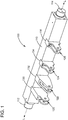
- FIG. 1 shows a perspective view of a device 100, with an elongate shaft 110 having a first end 112 and a second end 114. Each of the first and second ends 112, 114 is typically mounted on bearings to facilitate rotation of elongate shaft 110.
- a plurality of attachment devices 120, 122, 124, 126 are fastened along elongate shaft 110 and to which may be attached, for example, a control rod, which may then be used to control a variable vane of a stage of a gas turbine.
- Attachment devices 120, 122, 124, 126 extend from elongate shaft 110 and from its longitudinal axis L to varying degrees, as a consequence of their intended function in controlling, for example, variable vanes of a gas turbine.
- the varying radial lengths of the attachment devices 120, 122, 124, 126 with respect to elongate shaft 110 impart high stresses, particularly at those attachment devices extending furthest from elongate shaft 110. This requires the use of higher strength materials for elongate shaft 110 and attachment devices 120, 122, 124, 126.
- attachment devices 120, 122, 124, 126 are typically fitted into a flanged joint 130, 132, 134, 136 along the length of elongate shaft 110.
- This requires some fastening apparatus or method to fix, for example, attachment device 120 within flanged joint 130.
- Such apparatuses and methods often include, for example, threaded bolts, bonding, brazing, welding, etc., each of which increases the complexity and expense of manufacturing known shaft-like devices.
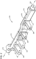
- FIG. 2 shows a perspective view of a stepped shaft assembly 200 according to one embodiment of the invention.
- Stepped shaft assembly 200 includes an elongate shaft body 210 with a first end 212 and a second end 214.
- elongate shaft body 210 includes a first portion 216 oriented substantially along a longitudinal axis L of the elongate shaft body 210 (i.e., a longitudinal axis extending through first and second ends 212, 214) and a second portion 218 oriented substantially parallel to and radially displaced to a distance D from the longitudinal axis L of the elongate shaft body 210. That is, second portion 218 includes a second longitudinal axis L' radially displaced from longitudinal axis L.
- a plurality of attachment devices 220, 222, 224, 226 is disposed along elongate shaft body 210.
- Each attachment device 220, 222, 224, 226 extends from either first portion 216 or second portion 218 to a distance d 1 , d 2 , d 3 , d 4 , respectively.
- the radial displacement of second portion 218 of elongate shaft body 210 from the longitudinal axis L permits the use of shorter attachment devices 220, 222, 224 along second portion 218.
- attachment devices 220, 222, 224 extend radially from second portion 218 (and from longitudinal axis L) to distances d 2 , d 3 , d 4 , respectively, which is a lesser distance than if second portion 218 was oriented substantially along longitudinal axis L.
- stepped shaft assembly 200 may be formed from less expensive, lower-strength materials than may be known devices.
- elongate shaft body 210 and attachment devices 220, 222, 224 may be forged or cast as a single unit. That is, attachment devices 220, 222, 224 may be structurally integrated into elongate shaft body 210 during the manufacturing process, obviating the need for joints into which attachment devices are inserted and into which the attachment devices must be fastened.
- a stepped shaft device may include more than one "stepped" portions radially displaced from the longitudinal axis of the elongate shaft body, each of the "stepped" portions being displaced to a different degree.
- Such an embodiment may be desirable where, for example, the extent of displacement is intended to be proportional to the lengths of the attachment devices that would otherwise be employed.
- attachment devices may be disposed along the lengths of any or each of the "stepped" portions.
- stepped shaft assembly 200 Materials from which stepped shaft assembly 200 may be formed include, for example, A514 steel, 2.25 Cr - 1 Mo steel, and carbon steel. Any such material may optionally include a coating or protectant, such as a rust protectant. Other suitable materials and other methods of forming stepped shaft assembly 200 will be apparent to one skilled in the art and are within the scope of the invention.
- a stepped shaft assembly according to embodiments of the invention has resulted in between about a 35% and a 40% reduction in stresses at the attachment devices.
- the total amount of material used in the cast stepped shaft assembly of FIG. 2 has been found to be reduced by between about 25% and about 30%.
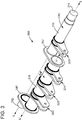
- FIG. 3 shows a perspective view of a stepped shaft assembly 300 according to another embodiment of the disclosure.
- stepped shaft assembly 300 comprises a welded or otherwise joined or fused configuration made up of a first cylindrical member 316 and a second cylindrical member 318.
- a first plate member 340 joins second cylindrical member 318 to a first end 312 and a second plate member 342 joins first cylindrical member 316 and second cylindrical member 318.
- second cylindrical member 318 is laterally displaced from the longitudinal axis L of stepped shaft assembly 300 to distance D by first plate member 340 and second plate member 342. That is, a second longitudinal axis L' of second cylindrical member 318 is radially displaced to distance D from longitudinal axis L extending through first and second ends 312, 314. Functionally, this is similar to the embodiment shown in FIG. 2 , resulting in decreased stresses at attachment devices 320, 322, 324. Also similar to the embodiment of FIG. 2 , therefore, stepped shaft assembly 300 may be formed from less expensive, lower-strength materials than may be known devices.
- Attachment devices 320, 322, 324, 326 may be affixed to first cylindrical member 316 or second cylindrical member 318 in any of a number of ways. As shown in FIG. 3 , attachment devices 320, 322, 324, 326 comprise a pair of adjacent, similarly-sized and similarly-shaped arms. These arms may, for example, be sized to slide over the exterior surface of first or second cylindrical member 316, 318 and welded or otherwise fixed in place. Alternatively, each of first and second cylindrical members 316, 318 may be made up of a plurality of shorter lengths which are affixed to and joined by attachment devices 320, 322, 324, 326.
- cylindrical members 316, 318 may be solid in cross-section. In other embodiments, cylindrical members 316, 318 may be tubular, i.e., hollow in cross-section. In embodiments in which cylindrical members 316, 318 are tubular, ends 312, 314 may be inserted into first plate member 340 and first cylindrical member 316, respectively.
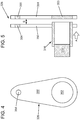
- FIG. 4 shows a side view of attachment device 326 of FIG. 3 .
- attachment device includes a body 350 having a first aperture 352 and a second aperture 354.
- First aperture 352 is sized and shaped to accommodate first cylindrical member 316.
- Second aperture 354 is sized and shaped to accommodate a device for securing, for example, a control rod, as discussed above.
- Apertures 352, 354 are shown as substantially circular, but may be of any shape compatible with, respectively, first cylindrical member 316 and the device for securing, for example, the control rod.
- FIG. 5 shows a top view of attachment device 326, which can be seen as comprising a pair of bodies 350, 351, a pair of first apertures 352 ( FIG. 4 ; obscured in FIG. 5 ), 354, and a pair of second apertures 354, 355, each aligned to accommodate passage of first cylindrical member 316 through first apertures 352, 353 along path A.
- Bodies 350, 351 are separated by a space S, such that, in place along either first or second cylindrical members 316, 318, bodies 350, 351 are spaced along or parallel to the longitudinal axis L ( FIG. 3 ).
- first cylindrical member 316 is tubular, having an internal dimension sized to accept second end 314, which may be solid rather than tubular.
- attachment device 326 may be fixed to first cylindrical member 316 by, for example, welding.
- second end 314 is passed into first cylindrical member 316 to the extent desired, second end 314 and first cylindrical member 316 may be fixed together by, for example, welding.
- FIGS. 6 and 7 show, respectively, side and top views of an attachment device 426 according to another embodiment of the invention briefly described above.
- the body 450 of attachment device 426 is truncated as compared to the embodiment of FIG. 4 .
- aperture 452 is substantially semi-circular rather than circular, as in FIG. 4 .
- FIG. 7 shows a top view of attachment device 426 in conjunction with two segments 416A, 416B of first cylindrical member 416 ( FIG. 4 ).
- segments 416A, 416B may effectively be joined, at least in part, by joining (via welding, etc.) body 450 to first segment 416A and by joining body 451 to second segment 416B.
- Segments 416A, 416B may optionally be directly joined as well, via welding, etc.
- an attachment device such as attachment device 426 may be used in combination with an unsegmented cylindrical member, such as first cylindrical member 316 ( FIGS. 3 and 5 ), with the bodies of such attachment devices joined to the unsegmented cylindrical member.
Landscapes
- Engineering & Computer Science (AREA)
- General Engineering & Computer Science (AREA)
- Mechanical Engineering (AREA)
- Ocean & Marine Engineering (AREA)
- Shafts, Cranks, Connecting Bars, And Related Bearings (AREA)
- Mutual Connection Of Rods And Tubes (AREA)
Abstract
There is provided a shaft assembly (200) for movement of a plurality of adjustable members. The shaft assembly comprises: an elongate shaft body (210) having: a first end (212) and a second end (214). A first portion (216) of the shaft assembly (200) is oriented substantially along a longitudinal axis (L, L) of the elongate shaft body (210). A second portion (218) of the shaft assembly (200) is oriented substantially parallel to and radially displaced from the longitudinal axis (L.,L) of the elongate shaft body (210). A plurality of crank-like attachment devices (220, 222, 224, 226) are disposed along an outer surface of the first portion (216) and the second portion (218) of the elongate shaft body (210).
Description
- Embodiments of the disclosure relate generally to shaft devices and, more particularly, to a shaft device having at least one portion that is radially distanced from a longitudinal axis of the shaft device.
- A first aspect of the disclosure provides a shaft assembly for movement of a plurality of adjustable members, the shaft assembly comprising: an elongate shaft body having: a first end; a second end; a first portion oriented substantially along a longitudinal axis of the elongate shaft body; and a second portion oriented substantially parallel to and radially displaced from the longitudinal axis of the elongate shaft body; and a plurality of attachment devices disposed along an outer surface of the elongate shaft body.
- The illustrative aspects of the present disclosure are designed to solve the problems herein described and/or other problems not discussed.
- These and other features of this disclosure will be more readily understood from the following detailed description of the various aspects of the disclosure taken in conjunction with the accompanying drawings that depict various embodiments of the disclosure, in which:
-
FIG. 1 is a perspective view of a shaft device; -
FIG. 2 is a perspective view of a shaft device according to one embodiment of the invention; -
FIG. 3 is a perspective view of a shaft device according to another embodiment of the invention. -
FIG. 4 is a side view of an attachment device according to an embodiment of the invention; -
FIG. 5 is a top view of the attachment device ofFIG. 4 in conjunction with components of a stepped shaft device according to an embodiment of the invention; -
FIG. 6 is a side view of an attachment device according to another embodiment of the invention; and -
FIG. 7 is a top view of the attachment device ofFIG. 6 in conjunction with components of a stepped shaft device according to another embodiment of the invention. - It is noted that the drawings of the disclosure are not to scale. The drawings are intended to depict only typical aspects of the disclosure, and therefore should not be considered as limiting the scope of the disclosure. In the drawings, like numbering represents like elements between the drawings.
- Shaft-like devices are commonly used to provide rotational control of arrays of vanes in compressors and gas turbines. Typically, such a device comprises an elongate member having a plurality of attachment devices along its length, to each of which an actuator rod or control rod may be connected.
-
FIG. 1 shows a perspective view of adevice 100, with anelongate shaft 110 having afirst end 112 and asecond end 114. Each of the first andsecond ends elongate shaft 110. A plurality ofattachment devices elongate shaft 110 and to which may be attached, for example, a control rod, which may then be used to control a variable vane of a stage of a gas turbine. -
Attachment devices elongate shaft 110 and from its longitudinal axis L to varying degrees, as a consequence of their intended function in controlling, for example, variable vanes of a gas turbine. The varying radial lengths of theattachment devices elongate shaft 110 impart high stresses, particularly at those attachment devices extending furthest fromelongate shaft 110. This requires the use of higher strength materials forelongate shaft 110 andattachment devices - In addition,
attachment devices flanged joint elongate shaft 110. This, however, requires some fastening apparatus or method to fix, for example,attachment device 120 within flangedjoint 130. Such apparatuses and methods often include, for example, threaded bolts, bonding, brazing, welding, etc., each of which increases the complexity and expense of manufacturing known shaft-like devices. -
FIG. 2 shows a perspective view of astepped shaft assembly 200 according to one embodiment of the invention. Steppedshaft assembly 200 includes anelongate shaft body 210 with afirst end 212 and asecond end 214. However, unlike the known device ofFIG. 1 ,elongate shaft body 210 includes afirst portion 216 oriented substantially along a longitudinal axis L of the elongate shaft body 210 (i.e., a longitudinal axis extending through first andsecond ends 212, 214) and asecond portion 218 oriented substantially parallel to and radially displaced to a distance D from the longitudinal axis L of theelongate shaft body 210. That is,second portion 218 includes a second longitudinal axis L' radially displaced from longitudinal axis L. - A plurality of
attachment devices elongate shaft body 210. Eachattachment device first portion 216 orsecond portion 218 to a distance d1, d2, d3, d4, respectively. The radial displacement ofsecond portion 218 ofelongate shaft body 210 from the longitudinal axis L permits the use ofshorter attachment devices second portion 218. That is,attachment devices second portion 218 was oriented substantially along longitudinal axis L. - The use of
shorter attachment devices attachment devices shaft assembly 200 may be formed from less expensive, lower-strength materials than may be known devices. In addition,elongate shaft body 210 andattachment devices attachment devices elongate shaft body 210 during the manufacturing process, obviating the need for joints into which attachment devices are inserted and into which the attachment devices must be fastened. - In other embodiments of the invention, a stepped shaft device may include more than one "stepped" portions radially displaced from the longitudinal axis of the elongate shaft body, each of the "stepped" portions being displaced to a different degree. Such an embodiment may be desirable where, for example, the extent of displacement is intended to be proportional to the lengths of the attachment devices that would otherwise be employed. In such an embodiment, attachment devices may be disposed along the lengths of any or each of the "stepped" portions.
- Materials from which stepped
shaft assembly 200 may be formed include, for example, A514 steel, 2.25 Cr - 1 Mo steel, and carbon steel. Any such material may optionally include a coating or protectant, such as a rust protectant. Other suitable materials and other methods of formingstepped shaft assembly 200 will be apparent to one skilled in the art and are within the scope of the invention. - In some cases, it has been found that the use of a stepped shaft assembly according to embodiments of the invention has resulted in between about a 35% and a 40% reduction in stresses at the attachment devices. At the same time, the total amount of material used in the cast stepped shaft assembly of
FIG. 2 has been found to be reduced by between about 25% and about 30%. -
FIG. 3 shows a perspective view of astepped shaft assembly 300 according to another embodiment of the disclosure. Here, rather than a singular cast body, steppedshaft assembly 300 comprises a welded or otherwise joined or fused configuration made up of a firstcylindrical member 316 and a secondcylindrical member 318. Afirst plate member 340 joins secondcylindrical member 318 to afirst end 312 and asecond plate member 342 joins firstcylindrical member 316 and secondcylindrical member 318. - As can be seen in
FIG. 3 , secondcylindrical member 318 is laterally displaced from the longitudinal axis L ofstepped shaft assembly 300 to distance D byfirst plate member 340 andsecond plate member 342. That is, a second longitudinal axis L' of secondcylindrical member 318 is radially displaced to distance D from longitudinal axis L extending through first andsecond ends FIG. 2 , resulting in decreased stresses atattachment devices FIG. 2 , therefore,stepped shaft assembly 300 may be formed from less expensive, lower-strength materials than may be known devices. -
Attachment devices cylindrical member 316 or secondcylindrical member 318 in any of a number of ways. As shown inFIG. 3 ,attachment devices cylindrical member cylindrical members attachment devices - In some embodiments of the invention,
cylindrical members cylindrical members cylindrical members ends first plate member 340 and firstcylindrical member 316, respectively. -
FIG. 4 shows a side view ofattachment device 326 ofFIG. 3 . As can be seen, attachment device includes abody 350 having afirst aperture 352 and asecond aperture 354.First aperture 352 is sized and shaped to accommodate firstcylindrical member 316.Second aperture 354 is sized and shaped to accommodate a device for securing, for example, a control rod, as discussed above.Apertures cylindrical member 316 and the device for securing, for example, the control rod. -
FIG. 5 shows a top view ofattachment device 326, which can be seen as comprising a pair ofbodies FIG. 4 ; obscured inFIG. 5 ), 354, and a pair ofsecond apertures cylindrical member 316 throughfirst apertures path A. Bodies cylindrical members bodies FIG. 3 ). As also shown inFIG. 5 , firstcylindrical member 316 is tubular, having an internal dimension sized to acceptsecond end 314, which may be solid rather than tubular. - Once first
cylindrical member 316 is passed through bothfirst apertures attachment device 326 may be fixed to firstcylindrical member 316 by, for example, welding. Similarly, oncesecond end 314 is passed into firstcylindrical member 316 to the extent desired,second end 314 and firstcylindrical member 316 may be fixed together by, for example, welding. -
FIGS. 6 and 7 show, respectively, side and top views of anattachment device 426 according to another embodiment of the invention briefly described above. Referring toFIG. 6 , thebody 450 ofattachment device 426 is truncated as compared to the embodiment ofFIG. 4 . Here,aperture 452 is substantially semi-circular rather than circular, as inFIG. 4 . -
FIG. 7 shows a top view ofattachment device 426 in conjunction with twosegments FIG. 4 ). Here,segments body 450 tofirst segment 416A and by joiningbody 451 tosecond segment 416B.Segments - In still another embodiment of the invention, an attachment device such as
attachment device 426 may be used in combination with an unsegmented cylindrical member, such as first cylindrical member 316 (FIGS. 3 and5 ), with the bodies of such attachment devices joined to the unsegmented cylindrical member. - The terminology used herein is for the purpose of describing particular embodiments only and is not intended to be limiting of the disclosure. As used herein, the singular forms "a," "an," and "the" are intended to include the plural forms as well, unless the context clearly indicates otherwise. It will be further understood that the terms "comprises" and/or "comprising," when used in this specification, specify the presence of stated features, integers, steps, operations, elements, and/or components, but do not preclude the presence or addition of one or more other features, integers, steps, operations, elements, components, and/or groups thereof.
- The corresponding structures, materials, acts, and equivalents of all means or step plus function elements in the claims below are intended to include any structure, material, or act for performing the function in combination with other claimed elements as specifically claimed. The description of the present disclosure has been presented for purposes of illustration and description, but is not intended to be exhaustive or limited to the disclosure in the form disclosed. Many modifications and variations will be apparent to those of ordinary skill in the art without departing from the scope and spirit of the disclosure. The embodiment was chosen and described in order to best explain the principles of the disclosure and the practical application, and to enable others of ordinary skill in the art to understand the disclosure for various embodiments with various modifications as are suited to the particular use contemplated.
- Various aspects and embodiments of the present invention are defined by the following numbered clauses:
- 1. A shaft assembly for movement of a plurality of adjustable members, the shaft assembly comprising:
- an elongate shaft body having:
- a first end;
- a second end;
- a first portion oriented substantially along a longitudinal axis of the elongate shaft body; and
- a second portion oriented substantially parallel to and radially displaced from the longitudinal axis of the elongate shaft body; and
- a plurality of attachment devices disposed along an outer surface of the elongate shaft body.
- an elongate shaft body having:
- 2. The shaft assembly of clause 1, wherein each of the first end and the second end of the elongate shaft body lies substantially along the longitudinal axis.
- 3. The shaft assembly of clause 1 or clause 2, wherein a first of the plurality of attachment devices is disposed on the first portion of the elongate shaft body and a second of the plurality of attachment devices is disposed on the second portion of the elongate shaft body.
- 4. The shaft assembly of any preceding clause, wherein at least one of the plurality of attachment devices is adapted for attachment to an actuator rod for moving the elongate shaft body.
- 5. The shaft assembly of any preceding clause, wherein the at least one of the plurality of attachment devices is disposed along the second portion of the elongate shaft body.
- 6. The shaft assembly of any preceding clause, further comprising:
- a third portion of the elongate shaft body,
- 7. The shaft assembly of any preceding clause, wherein a first of the plurality of attachment devices is disposed on the first portion of the elongate shaft body, a second of the plurality of attachment devices is disposed on the second portion of the elongate shaft body, and a third of the plurality of attachment devices is disposed on the third portion of the elongate shaft body.
- 8. The shaft assembly of any preceding clause, wherein each of the first portion and the second portion of the elongate shaft member comprises a substantially tubular member having a first end and a second end.
- 9. The shaft assembly of any preceding clause, further comprising:
- a first plate member disposed between the first portion and the second portion and to which each of a first end of the first portion and a second end of the second portion is attached.
- 10. The shaft assembly of any preceding clause, further comprising:
- a second plate member disposed between the first end of the elongate shaft body and the second portion and to which each of the first end of the elongate shaft body and a first end of the second portion is attached.
- 11. The shaft assembly of any preceding clause, wherein at least one of the plurality of attachment devices includes:
- a body extending radially from the outer surface of the elongate shaft body; and
- an aperture through at least a portion of the body, the aperture oriented substantially parallel to the longitudinal axis of the elongate shaft body.
- 12. The shaft assembly of any preceding clause, wherein the body includes a first member and a second member laterally separated along the outer surface of the elongate shaft body and the passage passes through both the first member and the second member.
- 13. The shaft assembly of any preceding clause, wherein:
- a first of the plurality of attachment devices is disposed along the first portion of the elongate shaft body, the body of the first of the plurality of attachment devices extending radially from the outer surface of the first portion to a first distance; and
- a second of the plurality of attachment devices is disposed along the second portion of the elongate shaft body, the body of the second of the plurality of attachment devices extending radially from the outer surface of the second portion to a second distance that is less than the first distance.
- 14. The shaft assembly of any preceding clause, wherein the body of the first of the plurality of attachment devices and the body of the second of the plurality of attachment devices extend radially from the longitudinal axis to substantially the same distance.
- 15. The shaft assembly of any preceding clause, wherein the first portion and the second portion of the elongate shaft member comprise a plurality of segmented tubular members.
- 16. The shaft assembly of any preceding clause, wherein at least one of the plurality of attachment devices includes:
- a body extending radially from the outer surface of the elongate shaft body; and
- an aperture through at least a portion of the body, the aperture oriented substantially parallel to the longitudinal axis of the elongate shaft body.
- 17. The shaft assembly of any preceding clause, wherein the aperture is substantially circular.
- 18. The shaft assembly of any preceding clause, wherein the aperture is substantially semi-circular
- 19. The shaft assembly of any preceding clause, wherein at least one of the attachment devices is joined to both a first and a second of the plurality of segmented tubular members.
- 20. The shaft assembly of any preceding clause, wherein the first of the plurality of segmented tubular members is joined to the second of the plurality of segmented tubular members.
Claims (15)
- A shaft assembly for movement of a plurality of adjustable members, the shaft assembly comprising:an elongate shaft body (210) having:a first end (212);a second end (214);a first portion (216) oriented substantially along a longitudinal axis of the elongate shaft body (210); anda second portion (218) oriented substantially parallel to and radially displaced from the longitudinal axis of the elongate shaft body (210); anda plurality of attachment devices (220, 222, 224, 226) disposed along an outer surface of the elongate shaft body (210).
- The shaft assembly of claim 1, wherein each of the first end (212) and the second end (214) of the elongate shaft body (210) lies substantially along the longitudinal axis.
- The shaft assembly of claim 1 or claim 2, wherein a first of the plurality of attachment devices (220, 222, 224, 226) is disposed on the first portion (216) of the elongate shaft body (210) and a second of the plurality of attachment devices (220, 222, 224, 226) is disposed on the second portion (218) of the elongate shaft body (210).
- The shaft assembly of any preceding claim, wherein at least one of the plurality of attachment devices (220, 222, 224, 226) is adapted for attachment to an actuator rod for moving the elongate shaft body (210).
- The shaft assembly of any preceding claim, wherein the at least one of the plurality of attachment devices (220, 222, 224) is disposed along the second portion (218) of the elongate shaft body (210).
- The shaft assembly of any preceding claim, further comprising:a third portion of the elongate shaft body,wherein the second portion is radially displaced from the longitudinal axis to a first distance and the third portion is radially displaced from the longitudinal axis to a second distance that is less than the first distance.
- The shaft assembly of any preceding claim, wherein a first of the plurality of attachment devices is disposed on the first portion of the elongate shaft body, a second of the plurality of attachment devices is disposed on the second portion of the elongate shaft body, and a third of the plurality of attachment devices is disposed on the third portion of the elongate shaft body.
- The shaft assembly of any preceding claim, wherein each of the first portion (316) and the second portion (318) of the elongate shaft (310) member comprises a substantially tubular member having a first end and a second end.
- The shaft assembly of any preceding claim, further comprising:a first plate member (342) disposed between the first portion (316) and the second portion (318) and to which each of a first end of the first portion (316) and a second end of the second portion (318) is attached.
- The shaft assembly of any preceding claim, further comprising:a second plate member (340) disposed between the first end (312) of the elongate shaft body (310) and the second portion (318) and to which each of the first end (312) of the elongate shaft body (310) and a first end of the second portion (318) is attached.
- The shaft assembly of claim 1, wherein at least one of the plurality of attachment devices (326) includes:a body (350) extending radially from the outer surface of the elongate shaft body (310); andan aperture (352) through at least a portion of the body (350), the aperture (352) oriented substantially parallel to the longitudinal axis of the elongate shaft body (310).
- The shaft assembly of any preceding claim, wherein the body (350) includes a first member and a second member laterally separated along the outer surface of the elongate shaft body (310) and the aperture (352, 353) passes through both the first member and the second member.
- The shaft assembly of any preceding claim, wherein:a first of the plurality of attachment devices (226) is disposed along the first portion (216) of the elongate shaft body (210), the body (350) of the first of the plurality of attachment devices (226) extending radially from the outer surface of the first portion (216) to a first distance; anda second of the plurality of attachment devices (224) is disposed along the second portion (218) of the elongate shaft body (210), the body (350) of the second of the plurality of attachment devices (224) extending radially from the outer surface of the second portion (218) to a second distance that is less than the first distance.
- The shaft assembly of any preceding claim, wherein the body of the first of the plurality of attachment devices and the body of the second of the plurality of attachment devices extend radially from the longitudinal axis to substantially the same distance.
- The shaft assembly of any preceding claim, wherein the first portion and the second portion of the elongate shaft member comprise a plurality of segmented tubular members.
Applications Claiming Priority (1)
| Application Number | Priority Date | Filing Date | Title |
|---|---|---|---|
| US14/885,199 US20170108032A1 (en) | 2015-10-16 | 2015-10-16 | Stepped shaft assembly |
Publications (1)
| Publication Number | Publication Date |
|---|---|
| EP3163031A1 true EP3163031A1 (en) | 2017-05-03 |
Family
ID=57137908
Family Applications (1)
| Application Number | Title | Priority Date | Filing Date |
|---|---|---|---|
| EP16193792.5A Withdrawn EP3163031A1 (en) | 2015-10-16 | 2016-10-13 | Cranked shaft with cranks to control a variable vane assembly |
Country Status (4)
| Country | Link |
|---|---|
| US (1) | US20170108032A1 (en) |
| EP (1) | EP3163031A1 (en) |
| JP (1) | JP2017089883A (en) |
| CN (1) | CN106884856A (en) |
Families Citing this family (1)
| Publication number | Priority date | Publication date | Assignee | Title |
|---|---|---|---|---|
| US10077799B2 (en) * | 2014-04-22 | 2018-09-18 | Regents Of The University Of Minnesota | Crankshaft assembly |
Citations (7)
| Publication number | Priority date | Publication date | Assignee | Title |
|---|---|---|---|---|
| US3487992A (en) * | 1967-11-01 | 1970-01-06 | Gen Electric | Stator adjusting mechanism for axial flow compressors |
| US6457937B1 (en) * | 2000-11-08 | 2002-10-01 | General Electric Company | Fabricated torque shaft |
| US6551057B1 (en) * | 1999-11-22 | 2003-04-22 | General Electric Company | Damped torque shaft assembly |
| US20090226305A1 (en) * | 2008-03-07 | 2009-09-10 | Albert Wong | Variable vane actuation system |
| EP2136036A1 (en) * | 2008-06-20 | 2009-12-23 | Rolls-Royce plc | Multi-rotational crankshaft arrangement |
| US20140133968A1 (en) * | 2012-11-15 | 2014-05-15 | United Technologies Corporation | Bellcrank for a variable vane assembly |
| EP2949878A1 (en) * | 2014-05-28 | 2015-12-02 | Rolls-Royce Deutschland Ltd & Co KG | A variable stator vane arrangement |
Family Cites Families (14)
| Publication number | Priority date | Publication date | Assignee | Title |
|---|---|---|---|---|
| US2325804A (en) * | 1940-08-17 | 1943-08-03 | Philco Corp | Crankshaft |
| US4460346A (en) * | 1980-05-30 | 1984-07-17 | General Steel Industries, Inc. | Eccentric shaft and method of manufacture |
| SE9904702L (en) * | 1998-12-28 | 2000-06-29 | Stihl Maschf Andreas | Short-term internal combustion engine |
| US6684755B2 (en) * | 2002-01-28 | 2004-02-03 | Bristol Compressors, Inc. | Crankshaft, compressor using crankshaft, and method for assembling a compressor including installing crankshaft |
| US7245040B2 (en) * | 2005-07-15 | 2007-07-17 | Honeywell International, Inc. | System and method for controlling the frequency output of dual-spool turbogenerators under varying load |
| CN102027267B (en) * | 2008-04-15 | 2014-07-09 | 舍弗勒技术股份两合公司 | Device for adjusting eccentricity for crank-CVT transmission |
| FR2930604B1 (en) * | 2008-04-24 | 2012-11-30 | Snecma | DEVICE FOR CONTROLLING VARIABLE-SETTING BLADES IN A TURBOMACHINE COMPRESSOR |
| EP2354560A1 (en) * | 2010-01-28 | 2011-08-10 | Siemens Aktiengesellschaft | Device for adjusting variable guide vanes |
| JP2012149743A (en) * | 2011-01-21 | 2012-08-09 | Ntn Corp | Shaft for engine |
| DE102011017068B4 (en) * | 2011-04-14 | 2015-01-15 | Thyssenkrupp Gerlach Gmbh | Crank drive for an internal combustion engine |
| US9068470B2 (en) * | 2011-04-21 | 2015-06-30 | General Electric Company | Independently-controlled gas turbine inlet guide vanes and variable stator vanes |
| US20140064912A1 (en) * | 2012-08-29 | 2014-03-06 | General Electric Company | Systems and Methods to Control Variable Stator Vanes in Gas Turbine Engines |
| US20170009579A1 (en) * | 2014-01-29 | 2017-01-12 | Suhua Liu | Reciprocating impact slack-drop/rotating/raking multifunctional power shaft |
| US10077799B2 (en) * | 2014-04-22 | 2018-09-18 | Regents Of The University Of Minnesota | Crankshaft assembly |
-
2015
- 2015-10-16 US US14/885,199 patent/US20170108032A1/en not_active Abandoned
-
2016
- 2016-10-06 JP JP2016197671A patent/JP2017089883A/en active Pending
- 2016-10-13 EP EP16193792.5A patent/EP3163031A1/en not_active Withdrawn
- 2016-10-14 CN CN201610897018.5A patent/CN106884856A/en active Pending
Patent Citations (7)
| Publication number | Priority date | Publication date | Assignee | Title |
|---|---|---|---|---|
| US3487992A (en) * | 1967-11-01 | 1970-01-06 | Gen Electric | Stator adjusting mechanism for axial flow compressors |
| US6551057B1 (en) * | 1999-11-22 | 2003-04-22 | General Electric Company | Damped torque shaft assembly |
| US6457937B1 (en) * | 2000-11-08 | 2002-10-01 | General Electric Company | Fabricated torque shaft |
| US20090226305A1 (en) * | 2008-03-07 | 2009-09-10 | Albert Wong | Variable vane actuation system |
| EP2136036A1 (en) * | 2008-06-20 | 2009-12-23 | Rolls-Royce plc | Multi-rotational crankshaft arrangement |
| US20140133968A1 (en) * | 2012-11-15 | 2014-05-15 | United Technologies Corporation | Bellcrank for a variable vane assembly |
| EP2949878A1 (en) * | 2014-05-28 | 2015-12-02 | Rolls-Royce Deutschland Ltd & Co KG | A variable stator vane arrangement |
Also Published As
| Publication number | Publication date |
|---|---|
| JP2017089883A (en) | 2017-05-25 |
| CN106884856A (en) | 2017-06-23 |
| US20170108032A1 (en) | 2017-04-20 |
Similar Documents
| Publication | Publication Date | Title |
|---|---|---|
| US6883761B2 (en) | Support for tubular members | |
| EP2388455B1 (en) | Exhaust gas turbocharger | |
| EP1255056A2 (en) | Stabilizer bar | |
| EP2484870A1 (en) | Blade of a turbomachine with damping element and method of designing a turbomachine | |
| EP2722486A1 (en) | Seal holder for a stator assembly | |
| WO2008022616A1 (en) | Delivery pipe for the transport of solids | |
| EP1359292A1 (en) | Lightweight valve | |
| WO2010063525A1 (en) | Guide blade arrangement for an axial turbo-machine | |
| EP3026229A1 (en) | Turbine housing for a turbocharger | |
| EP2492455A3 (en) | A gas turbine joint assembly | |
| EP3389919B1 (en) | Method for connection and tubular connection assembly for improved fatigue performance of metallic risers | |
| EP3163031A1 (en) | Cranked shaft with cranks to control a variable vane assembly | |
| EP4219897A1 (en) | Rotor having a balancing flange, rotor assembly having at least one rotor, and turbomachine having at least one rotor or having a rotor assembly | |
| US20070221459A1 (en) | Spring strut tube assembly | |
| EP1065392A2 (en) | Varying effective cross section shaft assembly | |
| US20100232870A1 (en) | Selectively reinforced piston pin | |
| DE102013209926A1 (en) | Adjustable damping valve device for vibration damper, has valve portion that is fluid-communicated with between pressurized surfaces which are axially spaced, so that valve poriton is axially pressure-balanced | |
| EP3353392B1 (en) | Valve for internal combustion engines having a guide vane for coolant | |
| CH663447A5 (en) | TURBO MACHINE WITH AT LEAST ONE RADIAL FLOWED WHEEL. | |
| EP1801348A2 (en) | Method for repairing a turbine engine vane assembly and repaired assembly | |
| CN110192027B (en) | Pitch adjustment cylinder for adjusting the pitch angle of a blade of a wind turbine | |
| JP2019039535A (en) | Riveting method and rivet | |
| EP3497333A1 (en) | Valve, more particularly a pump valve, for delivering abrasive and/or heterogeneous mixtures | |
| JP6935589B2 (en) | Wind Turbine Steel Tower Ring Segments and Methods | |
| EP3029268A1 (en) | Turbine rotor blade |
Legal Events
| Date | Code | Title | Description |
|---|---|---|---|
| PUAI | Public reference made under article 153(3) epc to a published international application that has entered the european phase |
Free format text: ORIGINAL CODE: 0009012 |
|
| AK | Designated contracting states |
Kind code of ref document: A1 Designated state(s): AL AT BE BG CH CY CZ DE DK EE ES FI FR GB GR HR HU IE IS IT LI LT LU LV MC MK MT NL NO PL PT RO RS SE SI SK SM TR |
|
| AX | Request for extension of the european patent |
Extension state: BA ME |
|
| STAA | Information on the status of an ep patent application or granted ep patent |
Free format text: STATUS: THE APPLICATION IS DEEMED TO BE WITHDRAWN |
|
| 18D | Application deemed to be withdrawn |
Effective date: 20171104 |