EP3163016A1 - Nose cone comprising a shaft balancing assembly - Google Patents
Nose cone comprising a shaft balancing assembly Download PDFInfo
- Publication number
- EP3163016A1 EP3163016A1 EP16191020.3A EP16191020A EP3163016A1 EP 3163016 A1 EP3163016 A1 EP 3163016A1 EP 16191020 A EP16191020 A EP 16191020A EP 3163016 A1 EP3163016 A1 EP 3163016A1
- Authority
- EP
- European Patent Office
- Prior art keywords
- flange
- nose cone
- cone
- shaft
- trailing edge
- Prior art date
- Legal status (The legal status is an assumption and is not a legal conclusion. Google has not performed a legal analysis and makes no representation as to the accuracy of the status listed.)
- Granted
Links
- 239000002131 composite material Substances 0.000 claims abstract description 12
- 230000000717 retained effect Effects 0.000 claims description 7
- 238000004519 manufacturing process Methods 0.000 description 9
- 230000008878 coupling Effects 0.000 description 7
- 238000010168 coupling process Methods 0.000 description 7
- 238000005859 coupling reaction Methods 0.000 description 7
- 229910052751 metal Inorganic materials 0.000 description 6
- 239000002184 metal Substances 0.000 description 6
- 238000000034 method Methods 0.000 description 4
- 229910052782 aluminium Inorganic materials 0.000 description 3
- XAGFODPZIPBFFR-UHFFFAOYSA-N aluminium Chemical compound [Al] XAGFODPZIPBFFR-UHFFFAOYSA-N 0.000 description 3
- 238000012986 modification Methods 0.000 description 3
- 230000004048 modification Effects 0.000 description 3
- 239000011347 resin Substances 0.000 description 3
- 229920005989 resin Polymers 0.000 description 3
- WFKWXMTUELFFGS-UHFFFAOYSA-N tungsten Chemical compound [W] WFKWXMTUELFFGS-UHFFFAOYSA-N 0.000 description 3
- 229910052721 tungsten Inorganic materials 0.000 description 3
- 239000010937 tungsten Substances 0.000 description 3
- 230000000712 assembly Effects 0.000 description 2
- 238000000429 assembly Methods 0.000 description 2
- 230000003628 erosive effect Effects 0.000 description 2
- 229910000765 intermetallic Inorganic materials 0.000 description 2
- 239000000463 material Substances 0.000 description 2
- 150000002739 metals Chemical class 0.000 description 2
- 230000008569 process Effects 0.000 description 2
- 238000011144 upstream manufacturing Methods 0.000 description 2
- 239000011800 void material Substances 0.000 description 2
- 238000004804 winding Methods 0.000 description 2
- OKTJSMMVPCPJKN-UHFFFAOYSA-N Carbon Chemical compound [C] OKTJSMMVPCPJKN-UHFFFAOYSA-N 0.000 description 1
- 229920000049 Carbon (fiber) Polymers 0.000 description 1
- 229910052799 carbon Inorganic materials 0.000 description 1
- 239000004917 carbon fiber Substances 0.000 description 1
- 230000008859 change Effects 0.000 description 1
- 239000011248 coating agent Substances 0.000 description 1
- 238000000576 coating method Methods 0.000 description 1
- 230000006835 compression Effects 0.000 description 1
- 238000007906 compression Methods 0.000 description 1
- 238000007796 conventional method Methods 0.000 description 1
- 230000007812 deficiency Effects 0.000 description 1
- 239000000835 fiber Substances 0.000 description 1
- 230000006870 function Effects 0.000 description 1
- 239000011521 glass Substances 0.000 description 1
- VNWKTOKETHGBQD-UHFFFAOYSA-N methane Chemical compound C VNWKTOKETHGBQD-UHFFFAOYSA-N 0.000 description 1
- 229920002635 polyurethane Polymers 0.000 description 1
- 239000004814 polyurethane Substances 0.000 description 1
- 230000001737 promoting effect Effects 0.000 description 1
- 230000004044 response Effects 0.000 description 1
- XLYOFNOQVPJJNP-UHFFFAOYSA-N water Substances O XLYOFNOQVPJJNP-UHFFFAOYSA-N 0.000 description 1
Images


Classifications
-
- F—MECHANICAL ENGINEERING; LIGHTING; HEATING; WEAPONS; BLASTING
- F04—POSITIVE - DISPLACEMENT MACHINES FOR LIQUIDS; PUMPS FOR LIQUIDS OR ELASTIC FLUIDS
- F04D—NON-POSITIVE-DISPLACEMENT PUMPS
- F04D29/00—Details, component parts, or accessories
- F04D29/66—Combating cavitation, whirls, noise, vibration or the like; Balancing
- F04D29/661—Combating cavitation, whirls, noise, vibration or the like; Balancing especially adapted for elastic fluid pumps
- F04D29/662—Balancing of rotors
-
- B—PERFORMING OPERATIONS; TRANSPORTING
- B64—AIRCRAFT; AVIATION; COSMONAUTICS
- B64C—AEROPLANES; HELICOPTERS
- B64C11/00—Propellers, e.g. of ducted type; Features common to propellers and rotors for rotorcraft
- B64C11/02—Hub construction
- B64C11/14—Spinners
-
- F—MECHANICAL ENGINEERING; LIGHTING; HEATING; WEAPONS; BLASTING
- F01—MACHINES OR ENGINES IN GENERAL; ENGINE PLANTS IN GENERAL; STEAM ENGINES
- F01D—NON-POSITIVE DISPLACEMENT MACHINES OR ENGINES, e.g. STEAM TURBINES
- F01D5/00—Blades; Blade-carrying members; Heating, heat-insulating, cooling or antivibration means on the blades or the members
- F01D5/02—Blade-carrying members, e.g. rotors
- F01D5/027—Arrangements for balancing
-
- F—MECHANICAL ENGINEERING; LIGHTING; HEATING; WEAPONS; BLASTING
- F02—COMBUSTION ENGINES; HOT-GAS OR COMBUSTION-PRODUCT ENGINE PLANTS
- F02C—GAS-TURBINE PLANTS; AIR INTAKES FOR JET-PROPULSION PLANTS; CONTROLLING FUEL SUPPLY IN AIR-BREATHING JET-PROPULSION PLANTS
- F02C7/00—Features, components parts, details or accessories, not provided for in, or of interest apart form groups F02C1/00 - F02C6/00; Air intakes for jet-propulsion plants
- F02C7/04—Air intakes for gas-turbine plants or jet-propulsion plants
-
- F—MECHANICAL ENGINEERING; LIGHTING; HEATING; WEAPONS; BLASTING
- F04—POSITIVE - DISPLACEMENT MACHINES FOR LIQUIDS; PUMPS FOR LIQUIDS OR ELASTIC FLUIDS
- F04D—NON-POSITIVE-DISPLACEMENT PUMPS
- F04D29/00—Details, component parts, or accessories
- F04D29/26—Rotors specially for elastic fluids
- F04D29/32—Rotors specially for elastic fluids for axial flow pumps
- F04D29/321—Rotors specially for elastic fluids for axial flow pumps for axial flow compressors
-
- F—MECHANICAL ENGINEERING; LIGHTING; HEATING; WEAPONS; BLASTING
- F04—POSITIVE - DISPLACEMENT MACHINES FOR LIQUIDS; PUMPS FOR LIQUIDS OR ELASTIC FLUIDS
- F04D—NON-POSITIVE-DISPLACEMENT PUMPS
- F04D29/00—Details, component parts, or accessories
- F04D29/26—Rotors specially for elastic fluids
- F04D29/32—Rotors specially for elastic fluids for axial flow pumps
- F04D29/325—Rotors specially for elastic fluids for axial flow pumps for axial flow fans
- F04D29/329—Details of the hub
-
- F—MECHANICAL ENGINEERING; LIGHTING; HEATING; WEAPONS; BLASTING
- F01—MACHINES OR ENGINES IN GENERAL; ENGINE PLANTS IN GENERAL; STEAM ENGINES
- F01D—NON-POSITIVE DISPLACEMENT MACHINES OR ENGINES, e.g. STEAM TURBINES
- F01D25/00—Component parts, details, or accessories, not provided for in, or of interest apart from, other groups
- F01D25/24—Casings; Casing parts, e.g. diaphragms, casing fastenings
- F01D25/243—Flange connections; Bolting arrangements
-
- F—MECHANICAL ENGINEERING; LIGHTING; HEATING; WEAPONS; BLASTING
- F05—INDEXING SCHEMES RELATING TO ENGINES OR PUMPS IN VARIOUS SUBCLASSES OF CLASSES F01-F04
- F05D—INDEXING SCHEME FOR ASPECTS RELATING TO NON-POSITIVE-DISPLACEMENT MACHINES OR ENGINES, GAS-TURBINES OR JET-PROPULSION PLANTS
- F05D2220/00—Application
- F05D2220/30—Application in turbines
- F05D2220/36—Application in turbines specially adapted for the fan of turbofan engines
-
- F—MECHANICAL ENGINEERING; LIGHTING; HEATING; WEAPONS; BLASTING
- F05—INDEXING SCHEMES RELATING TO ENGINES OR PUMPS IN VARIOUS SUBCLASSES OF CLASSES F01-F04
- F05D—INDEXING SCHEME FOR ASPECTS RELATING TO NON-POSITIVE-DISPLACEMENT MACHINES OR ENGINES, GAS-TURBINES OR JET-PROPULSION PLANTS
- F05D2250/00—Geometry
- F05D2250/20—Three-dimensional
- F05D2250/23—Three-dimensional prismatic
- F05D2250/232—Three-dimensional prismatic conical
-
- F—MECHANICAL ENGINEERING; LIGHTING; HEATING; WEAPONS; BLASTING
- F05—INDEXING SCHEMES RELATING TO ENGINES OR PUMPS IN VARIOUS SUBCLASSES OF CLASSES F01-F04
- F05D—INDEXING SCHEME FOR ASPECTS RELATING TO NON-POSITIVE-DISPLACEMENT MACHINES OR ENGINES, GAS-TURBINES OR JET-PROPULSION PLANTS
- F05D2260/00—Function
- F05D2260/30—Retaining components in desired mutual position
- F05D2260/31—Retaining bolts or nuts
-
- F—MECHANICAL ENGINEERING; LIGHTING; HEATING; WEAPONS; BLASTING
- F05—INDEXING SCHEMES RELATING TO ENGINES OR PUMPS IN VARIOUS SUBCLASSES OF CLASSES F01-F04
- F05D—INDEXING SCHEME FOR ASPECTS RELATING TO NON-POSITIVE-DISPLACEMENT MACHINES OR ENGINES, GAS-TURBINES OR JET-PROPULSION PLANTS
- F05D2260/00—Function
- F05D2260/96—Preventing, counteracting or reducing vibration or noise
-
- Y—GENERAL TAGGING OF NEW TECHNOLOGICAL DEVELOPMENTS; GENERAL TAGGING OF CROSS-SECTIONAL TECHNOLOGIES SPANNING OVER SEVERAL SECTIONS OF THE IPC; TECHNICAL SUBJECTS COVERED BY FORMER USPC CROSS-REFERENCE ART COLLECTIONS [XRACs] AND DIGESTS
- Y02—TECHNOLOGIES OR APPLICATIONS FOR MITIGATION OR ADAPTATION AGAINST CLIMATE CHANGE
- Y02T—CLIMATE CHANGE MITIGATION TECHNOLOGIES RELATED TO TRANSPORTATION
- Y02T50/00—Aeronautics or air transport
- Y02T50/60—Efficient propulsion technologies, e.g. for aircraft
Definitions
- the present disclosure relates generally to turbine machines, and more specifically to a nose cone and shaft balancing assembly for a turbine machine.
- Turbine machines provide energy for a wide range of uses.
- a turbine machine comprises at least a rotatable shaft and a plurality of blades.
- the plurality of blades comprise a fan.
- Examples of turbine machines include turbofan, turbojet, turboshaft, and turboprop engines; gas turbine engines; and wind turbines.
- the energy produced by a turbine machine is generally either electrical or mechanical.
- turbine machines are used to provide propulsion to an aircraft.
- a typical turbine engine comprises a compressor, a combustor, a highpressure turbine, and a low-pressure turbine.
- a nose cone upstream from the plurality of blades of the turbine machine.
- Nose cones are sometimes referred to in the art as “intake cones” or “inlet cones.”
- the nose cone can serve to reduce drag caused by the turbine machine, improve air flow to the plurality of blades, and avoid or limit damage potentially caused by impinging foreign objects.
- a nose cone is also advantageously used to slow the flow of air from supersonic flight speed to a subsonic speed before it enters the turbine machine.
- a turbine machine In many applications a turbine machine must be balanced after the nose cone is mounted to the rotatable shaft and without removing the nose cone. Balancing a turbine machine, or the fan of a turbine machine, with the nose cone attached ensures that the turbine will not experience excessive vibrations during operation which can be caused by uneven weight distribution. Uneven weight distribution can be addressed during the balancing procedure by attaching the balance weights to the nose cone, fan, shaft, or other part of the turbine machine.
- Fig. 1A is a partial sectional view of a nose cone 10 connected to a fan rotor 12 of an inlet fan of a gas turbine engine in accordance with conventional methods as described in U.S. Patent Application Publication No. 2011/0236217 .
- the illustrated nose cone 10 comprises a flange member 14 which tapers to a leading cone tip (not shown) and a region proximate the trailing edge 16 having a radial thickness greater than that of the remainder of the flange member 14.
- a support ring 18 having an axially-extending flange 20 is connected to the fan rotor 12.
- a bolt 22 engages the trailing edge 16 of nose cone 10 to an axial member 24 and support ring 18.
- FIG. 1B is a partial sectional view of a nose cone 10 connected to an inlet fan of a gas turbine engine as described in U.S. Patent No. 8,540,492 .
- a nose cone 10 comprises a flange member 14 which axially extends from leading cone tip (not shown) to a trailing edge 13.
- a radially thick mounting ring 26 is formed proximate the trailing edge 13.
- the mounting ring 26 defines a plurality of apertures 15 that are spaced apart about the circumference of the mounting ring 26.
- One or more of the apertures may include a recessed portion 17 for holding one or more balance weights 19.
- a fan rotor 12 is connected to retaining ring 28 having a mounting flange 30.
- a bolt 22 extends through an aperture 15 to connect nose cone 10 to the mounting flange 30. The bolt 22 also retains balance weight 19 within the recessed portion 17.
- the one or more balance weights 19 may be added or removed from recessed portions 17 without dismounting the nose cone 10 from the mounting flange 30.
- nose cone 10 allows for turbine balancing without the need to dismount the nose cone 10
- this configuration has its own drawbacks.
- fiber composite materials also called filament wound composites.
- a glass or carbon filament is wound around a rotating mandrel and, either contemporaneous with winding or after winding is complete, coated with a composite material resin which is then cured.
- the manufacture of components having varying thicknesses is difficult, time-consuming, and expensive.
- the nose cone 10 illustrated in Fig. 1B having an enlarged radial thickness at the mounting ring 26 is difficult, time-consuming, and expensive to manufacture.
- a turbine machine is understood to reference any machine using a turbine including gas turbine engines, wind turbines, steam turbines, water turbines, and the like.
- a turbine machine comprises at least a rotatable shaft and a plurality of blades.
- the present disclosure is directed to a nose cone for attachment to a turbine machine.
- the disclosed nose cone is advantageously used with any number of turbine machines, the embodiments below may describe the nose cone as used with a turbine engine, such as a gas turbine engine for aviation applications.
- a turbine engine such as a gas turbine engine for aviation applications.
- the disclosed apparatus, system, and method are not so limited.
- This disclosure presents embodiments to overcome the aforementioned deficiencies of nose cones and nose cone mounting configurations. More specifically, this disclosure is directed to a nose cone, nose cone assembly, and shaft balancing assembly which allow for turbine balancing with the nose cone connected to the turbine machine while additionally improving ease of manufacture. Detailed descriptions of the disclosed nose cone, nose cone assembly, and shaft balancing assembly, and additional advantages thereof, are presented below.
- Fig. 2 is a sectional view of an exemplary shaft balancing assembly 130 connected to a turbine machine 100 in accordance with some embodiments of the present disclosure.
- Fig. 3 is a detailed sectional view of an exemplary shaft balancing assembly 130 connected to a turbine machine 100 in accordance with some embodiments of the present disclosure.
- Turbine machine 100 comprises rotatable shaft 105, fan blisk 120, and a plurality of fan blades 121.
- Fan blisk 120 is mounted to rotatable shaft 105 via a mounting plate 107.
- Fan blisk 120 is a combination of a fan rotor and fan blades.
- fan blisk 120 additionally comprises a coupling flange 122 extending axially away from the fan blades 121 in an upstream direction.
- Coupling flange 122 has an aperture 123 adapted to receive an elongate fastener 134 such as a bolt, screw, or similar apparatus.
- nose cone 110 is mounted to a fan rotor in lieu of a fan blisk 120.
- nose cone 110 is mounted directly to a rotatable shaft 105 in lieu of a fan blisk 120.
- Shaft balancing assembly 130 comprises a nose cone 110, a plurality of elongate fasteners 134 removably connecting the nose cone 110 to fan blisk 120, and a plurality of balance weights 132.
- a shaft balancing assembly comprises a plurality of balance weights 132.
- Figs. 4A and 4B provide perspective views of nose cone 110
- Figs. 4C through 4G provide various sectional views of nose cone 110
- Nose cone 110 comprises a flange 118 extending axially from a leading tip 112 to a trailing edge 114. Nose cone 110 thus tapers from the circular trailing edge 114 to the leading tip 112.
- Nose cone 110 can have an elliptical, conical, or biconical shape.
- Nose cone 110 has a central axis A which is axially aligned with rotatable shaft 105 when nose cone 110 is mounted to the turbine machine 100.
- Flange 118 has an outer surface 116 which defines an airflow path for air impinging on nose cone 110.
- outer surface 116 may be coated with an erosion-resistant coating such as polyurethane.
- apertures 117 are formed in flange 118 along a circumference C proximate trailing edge 114.
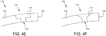
- apertures 117 each comprise a bore 113 and recessed portion 111 which can be seen in Figs. 4E and 4F .
- Bore 113 is adapted to receive the body 138 of elongated fastener 134
- recessed portion 111 is adapted to receive the head 137 of elongated fastener 134 or at least a portion of a balance weight 132 or both.
- Elongated fastener 134 is dimensioned such that the outer surface 159 of the head 137 is flush with the outer surface 116 of flange 118.
- recessed portion 111 is a counterbore as shown in Fig. 4E ; in other embodiments recessed portion 111 is a countersink as shown in Fig 4F . In still further embodiments recessed portion 111 is an aperture not limited to any particular shape or structure.
- nose cone 110 is formed from a filament wound composite material. In some embodiments, nose cone 110 is formed from a carbon fiber filament wound and coated in a resin which is subsequently cured prior to nose cone 110 use. During manufacture, flange 118 is formed as a uniform thickness and apertures 117 are added following resin cure.
- flange 118 has a uniform thickness from the leading point 112 to the trailing edge 114 excluding apertures 117.
- a uniform thickness provides for improved ease of manufacture of filament wound composites.
- flange 118 is formed with a thickness that does not vary by more than fifty percent from the leading tip 112 of nose cone 110 to the trailing edge 114 of the flange 118.
- flange 118 is formed with a thickness that does not vary by more than twenty-five percent from the leading tip 112 of nose cone 110 to the trailing edge 114 of the flange 118.
- nose cone 110 comprises a forward portion 145 defining leading point 112 and having a thickness greater than the thickness of flange 118.
- Flange 118 extends axially away from forward portion 145 starting at tangency point P and terminating at trailing edge 114. Between tangency point P and trailing edge 114, flange 118 has a uniform thickness excluding apertures 117.
- Nose cone 110 is mounted to fan blisk 120 by elongated fasteners 134 which are removably disposed in recessed portion 111, bore 113, and aperture 123.
- elongate fastener 134 is a threaded bolt held in place by a nut 136 which retains elongate fastener 134 with tension against coupling flange 122.
- aperture 123 is threaded and adapted to receive a threaded portion of elongate fastener 134.
- an alignment module 140 is additionally disposed between flange 118 and coupling flange 122.
- Alignment module 140 defines an alignment module bore 141 adapted to receive elongated fastener 134.
- Alignment module 140 is dimensioned to be removably located and abutted against coupling flange 122 and inner surface 115 of flange 118.
- Alignment module 140 is additionally positioned such that each module bore 141 is aligned with a bore 113 of aperture 117 to thereby form an aligned pair 150 of bore 113 and a module bore 141.
- Aligned pair 150 forms a recessed cavity 151, illustrated in Fig. 4G , adapted to receive a balancing weight 132 and elongated fastener 134.
- alignment module 140 is a compression molded material. In some embodiments alignment module 140 further comprises an alignment module recessed cavity 142 adapted to receive at least a portion of balance weight 132. Alignment module recessed cavity 142 can be formed as a counterbore, countersink, or similar structure.
- alignment module 140 is bonded to the inside surface 115 of flange 118. In other embodiments, alignment module 140 is held in place between flange 118 and coupling flange 122 by elongated fastener 134.
- a plurality of discrete alignment modules 140 are provided, with each alignment module 140 aligned with a aperture 117 of nose cone 110.
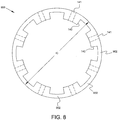
- alignment module 140 comprises a continuous ring 900 defining a plurality of module bores 141 spaced apart around an inner circumference IC of nose cone 110, the ring adhering to the inner surface 115 of flange 118 and being positioned so that each module bore 141 forms an aligned pair 150 with a aperture 117 of flange 118.
- Aligned pairs 150 each form a recessed cavity 151 adapted to receive a balancing weight 132 and elongated fastener 134.
- Fig. 8 is a profile view of a ring-type alignment module 900 comprising a plurality of alignment modules 140 connected together by circumferential portions 902. Each alignment module 140 defines at least an alignment module bore 141.
- the ring 900 is dimensioned to fit within the inner circumference IC of nose cone 110 proximate trailing edge 114.
- the elongated fastener 134 extends through an aligned pair 150 and engages a portion of the turbine machine 100 for mounting the nose cone 110 to the rotatable shaft 105, specifically the coupling flange 122.
- One or more of the elongated fasteners 134 retain one or more balance weights 132 within a aperture 117 and/or recessed cavity 151.
- Shaft balancing assembly 130 comprises a plurality of balance weights 132 which are shown in Figs 3 , 5A, and 5B .
- a balancing weight 132 is formed with a head portion 155 and body portion 156.
- Balancing weight 132 has a recessed cavity 157 which in some embodiments comprises a balancing weight bore 133 and balancing weight counterbore 135.
- a balancing weight 132 functions to transfer the clamping load of elongated fastener 134 to flange 118 of nose cone 110.
- balancing weight 132 is dimensioned such that the outer surface 158 of the head portion 155 is flush with outer surface 116 of flange 118.
- Balance weights 132 are formed to have varying or incremental masses.
- balance weights 132 are bimetallic, with the head 155 and an upper portion of body 156 formed from a first metal and a lower portion of body 156 formed from a second metal.
- a balancing weight 132 is disposed in recessed cavity 151 of aligned pair 150, or, in some embodiments simply in aperture 117 of nose cone 110. A balancing weight 132 is thus retained radially interior to the airflow path defined by the outer surface 116 of flange 118.
- the junction between the first and second metals can be set at a varying depth, as illustrated by a first depth D 1 , second depth D 2 , and third depth D 3 .
- a first depth D 1 , second depth D 2 , and third depth D 3 By varying the depth of the junction and the selection of the metals used to form a balancing weight 132, the mass of such balancing weight 132 can be varied.
- aluminum is used as the first metal and forms the head 155 and an upper portion of the body 156 of balancing weight 156.
- Tungsten is used as the second metal and forms a lower portion of the body 156 of balancing weight 156.
- a set of balance weights 132 with varying masses is provided as a kit for performing shaft balancing.
- Nose cone 110 is mounted to fan blisk 120 using a plurality of elongated fasteners 134, allowing for the removal of any one elongated fastener - or, indeed, of potentially several elongated fasteners 134 - at any one time while maintaining the nose cone 110 mounted to fan blisk 120.
- a balancing weight 132 of a first mass can be replaced with a balancing weight 132 of a second mass to aid in shaft balancing.
- a balancing weight 132 is removable from a aperture 117 of nose cone 110 while the nose cone 110 is mounted to rotatable shaft 120.
- an erosion resistant metallic insert 160 is disposed between flange 118 and balance weight 132. Metallic insert 160 provides protection to areas of the aperture 117 which may be exposed to the air flowpath.
- a modified balancing weight 232 does not completely fill recessed cavity 151, leaving a void 233.
- modified balancing weight 232 can be formed from a monometallic, bimetallic, metallic compound, or other material.
- each modified balancing weight 232 may be formed at a different depth resulting in a different volume and mass. Based on the depth of a given modified balancing weight 232, void 233 is larger or smaller as modified balance weights 232 are exchanged during the shaft balancing process.
- cup washers 332 are used as balance weights.
- Cup washer 332 comprises a lower portion 340 defining a washer bore 341 and an annular side portion 342 extending from lower portion 340 so as to form a washer cavity 343.
- a transfer insert 334 is disposed between the cup washer 332 and alignment module. Transfer insert 334 transfers clamp load from the elongated fastener 134 to flange 118 and covers areas of aperture 117 which are exposed to the air flowpath.
- transfer insert 334 is formed from a metallic compound.
- transfer insert 334 is adhered to flange 118.
- transfer insert 334 is dimensioned such that an outer surface 335 of transfer insert 334 is flush with outer surface 116 of flange 118.
- each cup washer 332 may have different dimensions resulting in a different volume and mass.
- the height of the annular side portion 342 of each cup washer 332 is varied through a set of cup washers 332 to achieve a set having varying masses.
- the disclosed nose cones, nose cone assemblies, and shaft balancing assemblies provide numerous advantages over the prior art.
- Elongated fastener heads 137 exposed to the air flowpath allow for balancing - such as fan trim balancing and shaft balancing - to be performed with the nose cone 110 mounted to the fan blisk 120. Because the nose cone 110 is mounted using a plurality of elongated fasteners 134, up to several elongated fasteners 134 can be removed at a time while maintaining the nose cone 110 mounted. This allows for change out of balance weights 132 or cup washers 332 during the balancing process.
- the disclosed nose cone 110 provides for improved ease of manufacturing over the prior art because flange 118 comprises a uniform thickness. During the manufacturing process for a filament wound composite, no non-uniform thicknesses such as an enlarged mounting flange need to be included. This makes manufacture of the disclosed nose cone 110 simpler, faster, and cheaper.
- a turbine machine comprises a rotatable shaft, a nose cone having a central axis mounted to the rotatable shaft so that the central axis is axially aligned with the rotatable shaft, the nose cone comprising a flange extending axially from a leading tip of the nose cone to a trailing edge at a base of the nose cone and radially around the central axis, the flange having an outer surface defining an airflow path and one or more apertures; and a shaft balancing assembly comprising one or more balance weights positioned at least partially in the one or more apertures, one or more of the balance weights being removable from the apertures while the nose cone is mounted to the shaft, wherein the flange is formed with a thickness that does not vary by more than fifty percent from the leading tip of the cone to the trailing edge of the flange, and wherein the shaft balancing assembly further comprises one or more alignment modules, each module defining one or more bores, the one or
- the flange may be formed with a substantially uniform thickness from said leading tip of said cone to said trailing edge of said flange.
- the flange may be formed from filament wound composite material.
- the flange may be formed from filament wound composite material.
- the flange may define a plurality of apertures along a circumference of said flange proximate said trailing edge, one or more modules being positioned to form an aligned pair of a flange aperture and a module bore with said apertures, each of said aligned pairs forming a recessed cavity.
- the turbine machine may omprise one or more elongated fasteners, each elongated fastener extending through an aligned pair, wherein one or more of said fasteners retain one or more balance weights within a recessed cavity.
- One or more of said fasteners may engage a portion of said turbine machine to thereby mount said nose cone to said shaft.
- One or more of said fasteners may engage a portion of a rotor that is rotated by said shaft.
- One or more of said balance weights may be retained radially interior to the airflow path defined by the outer surface of said flange.
- a balancing assembly for a rotating shaft in a turbine comprises a nose cone having a central axis and being adapted for mounting to the shaft so that the central axis is axially aligned with the shaft, the nose cone comprising a flange formed from filament wound composite material extending axially from a leading tip of the cone to a trailing edge at a base of the cone and radially around the central axis, the flange defining a plurality of apertures spaced apart around a circumference of the cone proximate the trailing edge of the flange, one or more alignment modules, each module defining one or more bores, the one or more modules adhering to an inner surface of the flange and being positioned so that each module bore is aligned with a flange aperture to thereby form an aligned pair of a flange aperture and a module bore, each of the aligned pairs forming a recessed cavity, one or more elongated fasteners,
- the alignment module may comprise a ring defining a plurality of bores spaced apart around a circumference thereof, said ring adhering to an inner surface of said flange and being positioned so that each bore forms an aligned pair with a flange aperture.
- the assembly may comprise a plurality of alignment modules, each module defining a single bore, each of said modules adhering to an inner surface of said flange and being positioned so that said module bore forms an aligned pair with a flange aperture.
- the flange may be formed with a uniform thickness from said leading tip of said cone to said trailing edge of said flange.
- the flange may be formed with a thickness that does not vary by more than fifty percent from said leading tip of said cone to said trailing edge of said flange.
- the flange may be formed with a thickness that does not vary by more than twenty-five percent from said leading tip of said cone to said trailing edge of said flange.
- One or more of said balance weights may be bimetallic.
- One or more balance weights may be retained within said one or more recessed cavities radially interior to an outer surface of said flange.
Abstract
Description
- The present disclosure relates generally to turbine machines, and more specifically to a nose cone and shaft balancing assembly for a turbine machine.
- Turbine machines provide energy for a wide range of uses. A turbine machine comprises at least a rotatable shaft and a plurality of blades. In some applications the plurality of blades comprise a fan. Examples of turbine machines include turbofan, turbojet, turboshaft, and turboprop engines; gas turbine engines; and wind turbines.
- The energy produced by a turbine machine is generally either electrical or mechanical. As one example, turbine machines are used to provide propulsion to an aircraft. A typical turbine engine comprises a compressor, a combustor, a highpressure turbine, and a low-pressure turbine.
- In some turbine machines, particularly in turbine engines used for aircraft applications, it is desirable to attach a nose cone upstream from the plurality of blades of the turbine machine. Nose cones are sometimes referred to in the art as "intake cones" or "inlet cones." The nose cone can serve to reduce drag caused by the turbine machine, improve air flow to the plurality of blades, and avoid or limit damage potentially caused by impinging foreign objects. In supersonic aircraft, a nose cone is also advantageously used to slow the flow of air from supersonic flight speed to a subsonic speed before it enters the turbine machine.
- In many applications a turbine machine must be balanced after the nose cone is mounted to the rotatable shaft and without removing the nose cone. Balancing a turbine machine, or the fan of a turbine machine, with the nose cone attached ensures that the turbine will not experience excessive vibrations during operation which can be caused by uneven weight distribution. Uneven weight distribution can be addressed during the balancing procedure by attaching the balance weights to the nose cone, fan, shaft, or other part of the turbine machine.
-
Fig. 1A is a partial sectional view of anose cone 10 connected to afan rotor 12 of an inlet fan of a gas turbine engine in accordance with conventional methods as described inU.S. Patent Application Publication No. 2011/0236217 . The illustratednose cone 10 comprises aflange member 14 which tapers to a leading cone tip (not shown) and a region proximate thetrailing edge 16 having a radial thickness greater than that of the remainder of theflange member 14. Asupport ring 18 having an axially-extendingflange 20 is connected to thefan rotor 12. Abolt 22 engages thetrailing edge 16 ofnose cone 10 to anaxial member 24 and supportring 18. One disadvantage of the configuration shown inFig. 1A and similar nose cone mounting configurations used in the art is that turbine balancing is difficult to perform because of the limited access to the plurality ofbolts 22 which holdnose cone 10 to thefan rotor 12. Balancing is therefore typically performed withnose cone 10 removed from thefan rotor 12, and the re-connection of thenose cone 10 after balancing can introduce new weight imbalances. - In response to the shortcomings of the mounting configuration and
nose cone 10 shown inFig. 1A , configurations were developed to allow for turbine balancing to be performed with thenose cone 10 installed.Fig. 1B is a partial sectional view of anose cone 10 connected to an inlet fan of a gas turbine engine as described inU.S. Patent No. 8,540,492 . As illustrated inFig. 1B , anose cone 10 comprises aflange member 14 which axially extends from leading cone tip (not shown) to atrailing edge 13. A radiallythick mounting ring 26 is formed proximate thetrailing edge 13. Themounting ring 26 defines a plurality of apertures 15 that are spaced apart about the circumference of themounting ring 26. One or more of the apertures may include a recessed portion 17 for holding one or more balance weights 19. Afan rotor 12 is connected to retainingring 28 having amounting flange 30. Abolt 22 extends through an aperture 15 to connectnose cone 10 to themounting flange 30. Thebolt 22 also retains balance weight 19 within the recessed portion 17. As can be appreciated, the one or more balance weights 19 may be added or removed from recessed portions 17 without dismounting thenose cone 10 from themounting flange 30. - Although the mounting configuration illustrated in
Fig. 1B allows for turbine balancing without the need to dismount thenose cone 10, this configuration has its own drawbacks. In particular, it is preferred to manufacturenose cone 10 from fiber composite materials, also called filament wound composites. Typically a glass or carbon filament is wound around a rotating mandrel and, either contemporaneous with winding or after winding is complete, coated with a composite material resin which is then cured. The manufacture of components having varying thicknesses is difficult, time-consuming, and expensive. Thus, thenose cone 10 illustrated inFig. 1B having an enlarged radial thickness at themounting ring 26 is difficult, time-consuming, and expensive to manufacture. - The following will be apparent from elements of the figures, which are provided for illustrative purposes and are not necessarily to scale.
-
Fig. 1A is a partial sectional view of a nose cone connected to a fan rotor of an inlet fan of a gas turbine engine. -
Fig. 1B is a partial sectional view of a nose cone connected to an inlet fan of a gas turbine engine. -
Fig. 2 is a sectional view of an exemplary shaft balancing assembly connected to a turbine machine in accordance with some embodiments of the present disclosure. -
Fig. 3 is a detailed sectional view of an exemplary shaft balancing assembly connected to a turbine machine in accordance with some embodiments of the present disclosure. -
Fig. 4A is a perspective view of a nose cone in accordance with some embodiments of the present disclosure. -
Fig. 4B is a perspective view of a nose cone in accordance with some embodiments of the present disclosure. -
Fig. 4C is a sectional view of a nose cone in accordance with some embodiments of the present disclosure. -
Fig. 4D is a sectional view of a nose cone in accordance with some embodiments of the present disclosure. -
Fig. 4E is a detailed sectional view of an aperture of a nose cone in accordance with some embodiments of the present disclosure. -
Fig. 4F is a detailed sectional view of an aperture of a nose cone in accordance with some embodiments of the present disclosure. -
Fig. 4G is a detailed sectional view of an aligned pair comprising a flange bore and a module bore in accordance with some embodiments of the present disclosure. -
Fig. 5A is a side profile view of a balancing weight in accordance with some embodiments of the present disclosure. -
Fig. 5B is a side profile view of a balancing weight in accordance with some embodiments of the present disclosure. -
Fig. 6 is a detailed sectional view of an exemplary shaft balancing assembly connected to a turbine machine in accordance with some embodiments of the present disclosure. -
Fig. 7 is a detailed sectional view of an exemplary shaft balancing assembly connected to a turbine machine in accordance with some embodiments of the present disclosure. -
Fig. 8 is a profile view of a ring-type alignment module in accordance with some embodiments of the present disclosure. - While the present disclosure is susceptible to various modifications and alternative forms, specific embodiments have been shown by way of example in the drawings and will be described in detail herein. It should be understood, however, that the present disclosure is not intended to be limited to the particular forms disclosed. Rather, the present disclosure is to cover all modifications, equivalents, and alternatives falling within the spirit and scope of the disclosure as defined by the appended claims.
- For the purposes of promoting an understanding of the principles of the disclosure, reference will now be made to a number of illustrative embodiments illustrated in the drawings and specific language will be used to describe the same.
- As used herein, a turbine machine is understood to reference any machine using a turbine including gas turbine engines, wind turbines, steam turbines, water turbines, and the like. A turbine machine comprises at least a rotatable shaft and a plurality of blades.
- The present disclosure is directed to a nose cone for attachment to a turbine machine. Although the disclosed nose cone is advantageously used with any number of turbine machines, the embodiments below may describe the nose cone as used with a turbine engine, such as a gas turbine engine for aviation applications. However, one of skill in the art would understand that the disclosed apparatus, system, and method are not so limited.
- This disclosure presents embodiments to overcome the aforementioned deficiencies of nose cones and nose cone mounting configurations. More specifically, this disclosure is directed to a nose cone, nose cone assembly, and shaft balancing assembly which allow for turbine balancing with the nose cone connected to the turbine machine while additionally improving ease of manufacture. Detailed descriptions of the disclosed nose cone, nose cone assembly, and shaft balancing assembly, and additional advantages thereof, are presented below.
-
Fig. 2 is a sectional view of an exemplaryshaft balancing assembly 130 connected to aturbine machine 100 in accordance with some embodiments of the present disclosure.Fig. 3 is a detailed sectional view of an exemplaryshaft balancing assembly 130 connected to aturbine machine 100 in accordance with some embodiments of the present disclosure. -
Turbine machine 100 comprisesrotatable shaft 105,fan blisk 120, and a plurality offan blades 121.Fan blisk 120 is mounted torotatable shaft 105 via a mountingplate 107.Fan blisk 120 is a combination of a fan rotor and fan blades. As illustrated inFig. 2 ,fan blisk 120 additionally comprises acoupling flange 122 extending axially away from thefan blades 121 in an upstream direction. Couplingflange 122 has anaperture 123 adapted to receive anelongate fastener 134 such as a bolt, screw, or similar apparatus. In some embodiments,nose cone 110 is mounted to a fan rotor in lieu of afan blisk 120. In other embodiments,nose cone 110 is mounted directly to arotatable shaft 105 in lieu of afan blisk 120. -
Shaft balancing assembly 130 comprises anose cone 110, a plurality ofelongate fasteners 134 removably connecting thenose cone 110 tofan blisk 120, and a plurality ofbalance weights 132. In some embodiments, a shaft balancing assembly comprises a plurality ofbalance weights 132. -
Figs. 4A and 4B provide perspective views ofnose cone 110, whileFigs. 4C through 4G provide various sectional views ofnose cone 110.Nose cone 110 comprises aflange 118 extending axially from a leadingtip 112 to a trailingedge 114.Nose cone 110 thus tapers from thecircular trailing edge 114 to the leadingtip 112.Nose cone 110 can have an elliptical, conical, or biconical shape.Nose cone 110 has a central axis A which is axially aligned withrotatable shaft 105 whennose cone 110 is mounted to theturbine machine 100. -
Flange 118 has anouter surface 116 which defines an airflow path for air impinging onnose cone 110. In some embodiments,outer surface 116 may be coated with an erosion-resistant coating such as polyurethane. - A plurality of
apertures 117 are formed inflange 118 along a circumference Cproximate trailing edge 114. In some embodiments,apertures 117 each comprise abore 113 and recessedportion 111 which can be seen inFigs. 4E and 4F .Bore 113 is adapted to receive thebody 138 ofelongated fastener 134, and recessedportion 111 is adapted to receive thehead 137 ofelongated fastener 134 or at least a portion of abalance weight 132 or both.Elongated fastener 134 is dimensioned such that theouter surface 159 of thehead 137 is flush with theouter surface 116 offlange 118. - In some embodiments recessed
portion 111 is a counterbore as shown inFig. 4E ; in other embodiments recessedportion 111 is a countersink as shown inFig 4F . In still further embodiments recessedportion 111 is an aperture not limited to any particular shape or structure. - In some embodiments,
nose cone 110 is formed from a filament wound composite material. In some embodiments,nose cone 110 is formed from a carbon fiber filament wound and coated in a resin which is subsequently cured prior tonose cone 110 use. During manufacture,flange 118 is formed as a uniform thickness andapertures 117 are added following resin cure. - In some embodiments, as illustrated in
Fig. 4C ,flange 118 has a uniform thickness from theleading point 112 to the trailingedge 114 excludingapertures 117. A uniform thickness provides for improved ease of manufacture of filament wound composites. In other embodiments,flange 118 is formed with a thickness that does not vary by more than fifty percent from the leadingtip 112 ofnose cone 110 to the trailingedge 114 of theflange 118. In still further embodiments,flange 118 is formed with a thickness that does not vary by more than twenty-five percent from the leadingtip 112 ofnose cone 110 to the trailingedge 114 of theflange 118. - In some embodiments, as illustrated in
Fig. 4D ,nose cone 110 comprises aforward portion 145 definingleading point 112 and having a thickness greater than the thickness offlange 118.Flange 118 extends axially away fromforward portion 145 starting at tangency point P and terminating at trailingedge 114. Between tangency point P and trailingedge 114,flange 118 has a uniformthickness excluding apertures 117. -
Nose cone 110 is mounted tofan blisk 120 byelongated fasteners 134 which are removably disposed in recessedportion 111, bore 113, andaperture 123. In some embodiments elongatefastener 134 is a threaded bolt held in place by anut 136 which retainselongate fastener 134 with tension againstcoupling flange 122. In someembodiments aperture 123 is threaded and adapted to receive a threaded portion ofelongate fastener 134. - In some embodiments an
alignment module 140 is additionally disposed betweenflange 118 andcoupling flange 122.Alignment module 140 defines an alignment module bore 141 adapted to receiveelongated fastener 134.Alignment module 140 is dimensioned to be removably located and abutted againstcoupling flange 122 andinner surface 115 offlange 118.Alignment module 140 is additionally positioned such that each module bore 141 is aligned with abore 113 ofaperture 117 to thereby form an alignedpair 150 ofbore 113 and amodule bore 141. Alignedpair 150 forms a recessedcavity 151, illustrated inFig. 4G , adapted to receive a balancingweight 132 andelongated fastener 134. - In some
embodiments alignment module 140 is a compression molded material. In someembodiments alignment module 140 further comprises an alignment module recessedcavity 142 adapted to receive at least a portion ofbalance weight 132. Alignment module recessedcavity 142 can be formed as a counterbore, countersink, or similar structure. - In some
embodiments alignment module 140 is bonded to theinside surface 115 offlange 118. In other embodiments,alignment module 140 is held in place betweenflange 118 andcoupling flange 122 byelongated fastener 134. - In some embodiments a plurality of
discrete alignment modules 140 are provided, with eachalignment module 140 aligned with aaperture 117 ofnose cone 110. In otherembodiments alignment module 140 comprises acontinuous ring 900 defining a plurality of module bores 141 spaced apart around an inner circumference IC ofnose cone 110, the ring adhering to theinner surface 115 offlange 118 and being positioned so that each module bore 141 forms an alignedpair 150 with aaperture 117 offlange 118. Alignedpairs 150 each form a recessedcavity 151 adapted to receive a balancingweight 132 andelongated fastener 134. -
Fig. 8 is a profile view of a ring-type alignment module 900 comprising a plurality ofalignment modules 140 connected together bycircumferential portions 902. Eachalignment module 140 defines at least an alignment module bore 141. Thering 900 is dimensioned to fit within the inner circumference IC ofnose cone 110proximate trailing edge 114. - In embodiments having discrete- and ring-
type alignment modules 140, theelongated fastener 134 extends through an alignedpair 150 and engages a portion of theturbine machine 100 for mounting thenose cone 110 to therotatable shaft 105, specifically thecoupling flange 122. One or more of theelongated fasteners 134 retain one ormore balance weights 132 within aaperture 117 and/or recessedcavity 151. -
Shaft balancing assembly 130 comprises a plurality ofbalance weights 132 which are shown inFigs 3 ,5A, and 5B . In some embodiments a balancingweight 132 is formed with ahead portion 155 andbody portion 156. Balancingweight 132 has a recessedcavity 157 which in some embodiments comprises a balancing weight bore 133 and balancingweight counterbore 135. As illustrated, a balancingweight 132 functions to transfer the clamping load ofelongated fastener 134 to flange 118 ofnose cone 110. Further, balancingweight 132 is dimensioned such that theouter surface 158 of thehead portion 155 is flush withouter surface 116 offlange 118. -
Balance weights 132 are formed to have varying or incremental masses. In one embodiment,balance weights 132 are bimetallic, with thehead 155 and an upper portion ofbody 156 formed from a first metal and a lower portion ofbody 156 formed from a second metal. When installed, a balancingweight 132 is disposed in recessedcavity 151 of alignedpair 150, or, in some embodiments simply inaperture 117 ofnose cone 110. A balancingweight 132 is thus retained radially interior to the airflow path defined by theouter surface 116 offlange 118. - As illustrated in
Fig. 5B , the junction between the first and second metals can be set at a varying depth, as illustrated by a first depth D1, second depth D2, and third depth D3. By varying the depth of the junction and the selection of the metals used to form a balancingweight 132, the mass ofsuch balancing weight 132 can be varied. - As an example, aluminum is used as the first metal and forms the
head 155 and an upper portion of thebody 156 of balancingweight 156. Tungsten is used as the second metal and forms a lower portion of thebody 156 of balancingweight 156. When the junction between the aluminum and tungsten is set at depth D1, a first mass is achieved in the balancingweight 132. When the junction between the aluminum and tungsten is set at depth D2, a second mass is achieved in the balancingweight 132 with second mass being larger than first mass. - In some embodiments a set of
balance weights 132 with varying masses is provided as a kit for performing shaft balancing.Nose cone 110 is mounted tofan blisk 120 using a plurality ofelongated fasteners 134, allowing for the removal of any one elongated fastener - or, indeed, of potentially several elongated fasteners 134 - at any one time while maintaining thenose cone 110 mounted tofan blisk 120. Upon removal of anelongated fastener 134, a balancingweight 132 of a first mass can be replaced with a balancingweight 132 of a second mass to aid in shaft balancing. Thus a balancingweight 132 is removable from aaperture 117 ofnose cone 110 while thenose cone 110 is mounted torotatable shaft 120. - In some embodiments, an erosion resistant
metallic insert 160 is disposed betweenflange 118 andbalance weight 132.Metallic insert 160 provides protection to areas of theaperture 117 which may be exposed to the air flowpath. - In another embodiment presented in
Fig. 6 , a modified balancingweight 232 does not completely fill recessedcavity 151, leaving avoid 233. In this embodiment, modified balancingweight 232 can be formed from a monometallic, bimetallic, metallic compound, or other material. To achieve varying masses in a set of modifiedbalance weights 232, each modified balancingweight 232 may be formed at a different depth resulting in a different volume and mass. Based on the depth of a given modified balancingweight 232, void 233 is larger or smaller as modifiedbalance weights 232 are exchanged during the shaft balancing process. - In another embodiment presented in
Fig. 7 ,cup washers 332 are used as balance weights.Cup washer 332 comprises alower portion 340 defining awasher bore 341 and anannular side portion 342 extending fromlower portion 340 so as to form awasher cavity 343. Atransfer insert 334 is disposed between thecup washer 332 and alignment module.Transfer insert 334 transfers clamp load from theelongated fastener 134 toflange 118 and covers areas ofaperture 117 which are exposed to the air flowpath. In some embodiments transferinsert 334 is formed from a metallic compound. In some embodiments transferinsert 334 is adhered toflange 118. In some embodiments transferinsert 334 is dimensioned such that anouter surface 335 oftransfer insert 334 is flush withouter surface 116 offlange 118. - To achieve varying masses in a set of
cup washers 332, eachcup washer 332 may have different dimensions resulting in a different volume and mass. In some embodiments the height of theannular side portion 342 of eachcup washer 332 is varied through a set ofcup washers 332 to achieve a set having varying masses. - The disclosed nose cones, nose cone assemblies, and shaft balancing assemblies provide numerous advantages over the prior art. Elongated fastener heads 137 exposed to the air flowpath allow for balancing - such as fan trim balancing and shaft balancing - to be performed with the
nose cone 110 mounted to thefan blisk 120. Because thenose cone 110 is mounted using a plurality ofelongated fasteners 134, up to severalelongated fasteners 134 can be removed at a time while maintaining thenose cone 110 mounted. This allows for change out ofbalance weights 132 orcup washers 332 during the balancing process. - Further, the disclosed
nose cone 110 provides for improved ease of manufacturing over the prior art becauseflange 118 comprises a uniform thickness. During the manufacturing process for a filament wound composite, no non-uniform thicknesses such as an enlarged mounting flange need to be included. This makes manufacture of the disclosednose cone 110 simpler, faster, and cheaper. - The present application discloses one or more of the features recited in the appended claims and/or the following features which, alone or in any combination, may comprise patentable subject matter.
- According to an aspect of the present disclosure, a turbine machine comprises a rotatable shaft, a nose cone having a central axis mounted to the rotatable shaft so that the central axis is axially aligned with the rotatable shaft, the nose cone comprising a flange extending axially from a leading tip of the nose cone to a trailing edge at a base of the nose cone and radially around the central axis, the flange having an outer surface defining an airflow path and one or more apertures; and a shaft balancing assembly comprising one or more balance weights positioned at least partially in the one or more apertures, one or more of the balance weights being removable from the apertures while the nose cone is mounted to the shaft, wherein the flange is formed with a thickness that does not vary by more than fifty percent from the leading tip of the cone to the trailing edge of the flange, and wherein the shaft balancing assembly further comprises one or more alignment modules, each module defining one or more bores, the one or more modules adhering to an inner surface of the flange and being positioned so that each module bore is aligned with a flange aperture to thereby form an aligned pair of a flange aperture and a module bore, each of the aligned pairs forming a recessed cavity
- The flange may be formed with a substantially uniform thickness from said leading tip of said cone to said trailing edge of said flange.
- The flange may be formed from filament wound composite material.
- The flange may be formed from filament wound composite material.
- The flange may define a plurality of apertures along a circumference of said flange proximate said trailing edge, one or more modules being positioned to form an aligned pair of a flange aperture and a module bore with said apertures, each of said aligned pairs forming a recessed cavity.
- The turbine machine may omprise one or more elongated fasteners, each elongated fastener extending through an aligned pair, wherein one or more of said fasteners retain one or more balance weights within a recessed cavity.
- One or more of said fasteners may engage a portion of said turbine machine to thereby mount said nose cone to said shaft.
- One or more of said fasteners may engage a portion of a rotor that is rotated by said shaft.
- One or more of said balance weights may be retained radially interior to the airflow path defined by the outer surface of said flange..
- According to an aspect of the present disclosure, a balancing assembly for a rotating shaft in a turbine comprises a nose cone having a central axis and being adapted for mounting to the shaft so that the central axis is axially aligned with the shaft, the nose cone comprising a flange formed from filament wound composite material extending axially from a leading tip of the cone to a trailing edge at a base of the cone and radially around the central axis, the flange defining a plurality of apertures spaced apart around a circumference of the cone proximate the trailing edge of the flange, one or more alignment modules, each module defining one or more bores, the one or more modules adhering to an inner surface of the flange and being positioned so that each module bore is aligned with a flange aperture to thereby form an aligned pair of a flange aperture and a module bore, each of the aligned pairs forming a recessed cavity, one or more elongated fasteners, each fastener being positioned to extend through an aligned pair of a flange aperture and a module bore and being adapted to mount the cone to the shaft, and one or more balance weights, each of the balance weights being retained within a recessed cavity by an elongated fastener
- The alignment module may comprise a ring defining a plurality of bores spaced apart around a circumference thereof, said ring adhering to an inner surface of said flange and being positioned so that each bore forms an aligned pair with a flange aperture.
- The assembly may comprise a plurality of alignment modules, each module defining a single bore, each of said modules adhering to an inner surface of said flange and being positioned so that said module bore forms an aligned pair with a flange aperture.
- The flange may be formed with a uniform thickness from said leading tip of said cone to said trailing edge of said flange.
- The flange may be formed with a thickness that does not vary by more than fifty percent from said leading tip of said cone to said trailing edge of said flange.
- The flange may be formed with a thickness that does not vary by more than twenty-five percent from said leading tip of said cone to said trailing edge of said flange.
- One or more of said balance weights may be bimetallic.
- One or more balance weights may be retained within said one or more recessed cavities radially interior to an outer surface of said flange..
- Although examples are illustrated and described herein, embodiments are nevertheless not limited to the details shown, since various modifications and structural changes may be made therein by those of ordinary skill within the scope and range of equivalents of the claims.
Claims (15)
- A turbine machine comprising:a rotatable shaft;a nose cone having a central axis mounted to said rotatable shaft so that said central axis is axially aligned with said rotatable shaft, said nose cone comprising a flange extending axially from a leading tip of said nose cone to a trailing edge at a base of said nose cone and radially around said central axis, said flange having an outer surface defining an airflow path and one or more apertures; anda shaft balancing assembly comprising one or more balance weights positioned at least partially in said one or more apertures, one or more of said balance weights being removable from said apertures while said nose cone is mounted to said shaft,wherein said flange is formed with a thickness that does not vary by more than fifty percent from said leading tip of said cone to said trailing edge of said flange, and wherein said shaft balancing assembly further comprises one or more alignment modules, each module defining one or more bores, said one or more modules adhering to an inner surface of said flange and being positioned so that each module bore is aligned with a flange aperture to thereby form an aligned pair of a flange aperture and a module bore, each of said aligned pairs forming a recessed cavity.
- The turbine machine of Claim 1 wherein said flange is formed with a substantially uniform thickness from said leading tip of said cone to said trailing edge of said flange.
- The turbine machine of Claim 1 or Claim 2 wherein said flange is formed from filament wound composite material.
- The turbine machine of any preceding Claim wherein said flange defines a plurality of apertures along a circumference of said flange proximate said trailing edge, one or more modules being positioned to form an aligned pair of a flange aperture and a module bore with said apertures, each of said aligned pairs forming a recessed cavity.
- The turbine machine of Claim 4 comprising one or more elongated fasteners, each elongated fastener extending through an aligned pair, wherein one or more of said fasteners retain one or more balance weights within a recessed cavity.
- The turbine machine of Claim 5 wherein one or more of said fasteners engage a portion of said turbine machine to thereby mount said nose cone to said shaft.
- The turbine machine of Claim 6 wherein said one or more of said fasteners engage a portion of a rotor that is rotated by said shaft.
- The turbine machine of Claim 5 wherein one or more of said balance weights are retained radially interior to the airflow path defined by the outer surface of said flange.
- A balancing assembly for a rotating shaft in a turbine, said assembly comprising:a nose cone having a central axis and being adapted for mounting to the shaft so that said central axis is axially aligned with the shaft, said nose cone comprising a flange formed from filament wound composite material extending axially from a leading tip of said cone to a trailing edge at a base of said cone and radially around said central axis, said flange defining a plurality of apertures spaced apart around a circumference of said cone proximate said trailing edge of said flange;one or more alignment modules, each module defining one or more bores, said one or more modules adhering to an inner surface of said flange and being positioned so that each module bore is aligned with a flange aperture to thereby form an aligned pair of a flange aperture and a module bore, each of said aligned pairs forming a recessed cavity;one or more elongated fasteners, each fastener being positioned to extend through an aligned pair of a flange aperture and a module bore and being adapted to mount said cone to the shaft; andone or more balance weights, each of said balance weights being retained within a recessed cavity by an elongated fastener.
- The assembly of Claim 9 wherein said alignment module comprises a ring defining a plurality of bores spaced apart around a circumference thereof, said ring adhering to an inner surface of said flange and being positioned so that each bore forms an aligned pair with a flange aperture.
- The assembly of Claim 9 comprising a plurality of alignment modules, each module defining a single bore, each of said modules adhering to an inner surface of said flange and being positioned so that said module bore forms an aligned pair with a flange aperture.
- The assembly of any of Claims 9 to 11 wherein said flange is formed with a uniform thickness from said leading tip of said cone to said trailing edge of said flange.
- The assembly of any of Claims 9 to 11 wherein said flange is formed with a thickness that does not vary by more than fifty percent from said leading tip of said cone to said trailing edge of said flange.
- The assembly of Claim 13 wherein said flange is formed with a thickness that does not vary by more than twenty-five percent from said leading tip of said cone to said trailing edge of said flange.
- The assembly of any of Claims 9 to 14 wherein one or more of said balance weights are bimetallic; and/or.
wherein said one or more balance weights are retained within said one or more recessed cavities radially interior to an outer surface of said flange.
Applications Claiming Priority (1)
| Application Number | Priority Date | Filing Date | Title |
|---|---|---|---|
| US14/922,807 US9879698B2 (en) | 2015-10-26 | 2015-10-26 | Nose cone and shaft balancing assembly |
Publications (2)
| Publication Number | Publication Date |
|---|---|
| EP3163016A1 true EP3163016A1 (en) | 2017-05-03 |
| EP3163016B1 EP3163016B1 (en) | 2022-07-06 |
Family
ID=57218675
Family Applications (1)
| Application Number | Title | Priority Date | Filing Date |
|---|---|---|---|
| EP16191020.3A Active EP3163016B1 (en) | 2015-10-26 | 2016-09-28 | Nose cone comprising a shaft balancing assembly |
Country Status (3)
| Country | Link |
|---|---|
| US (1) | US9879698B2 (en) |
| EP (1) | EP3163016B1 (en) |
| CA (1) | CA2939505C (en) |
Cited By (4)
| Publication number | Priority date | Publication date | Assignee | Title |
|---|---|---|---|---|
| EP3450688A1 (en) * | 2017-08-29 | 2019-03-06 | United Technologies Corporation | Conical fan hub and method for reducing blade off loads |
| EP3663530A1 (en) * | 2018-12-07 | 2020-06-10 | Safran Aircraft Engines | Fan comprising an inter-blade platform |
| EP3786066A1 (en) * | 2019-08-27 | 2021-03-03 | Pratt & Whitney Canada Corp. | Fan nose cone and dynamic tuning of aircrafts |
| FR3110637A1 (en) * | 2020-05-19 | 2021-11-26 | Safran Aircraft Engines | THROUGH HOLE FOR MOTOR BALANCING SCREWS |
Families Citing this family (5)
| Publication number | Priority date | Publication date | Assignee | Title |
|---|---|---|---|---|
| CN105222742A (en) * | 2014-05-26 | 2016-01-06 | 通用电气公司 | Slurry is apart from fault detection system and method |
| FR3063308B1 (en) * | 2017-02-24 | 2019-04-26 | Safran Aircraft Engines | CAP FOR TURBOMACHINE ROTATING INPUT COVER, COMPRISING AERODYNAMIC EXTERNAL WALL AND CONE FASTENER |
| US10583913B2 (en) * | 2017-03-14 | 2020-03-10 | General Electric Company | Stud push out mount for a turbine engine spinner assembly having a spinner push out stud joint connecting through a counterbore of a spinner bolt hole |
| US10502133B2 (en) * | 2017-06-12 | 2019-12-10 | General Electric Company | Fastener cover for flowpath fasteners |
| US10697300B2 (en) * | 2017-12-14 | 2020-06-30 | Raytheon Technologies Corporation | Rotor balance weight system |
Citations (6)
| Publication number | Priority date | Publication date | Assignee | Title |
|---|---|---|---|---|
| US4393650A (en) * | 1977-04-20 | 1983-07-19 | Rolls-Royce Limited | Gas turbine engine having an automatic ice shedding spinner |
| FR2908827A1 (en) * | 2006-11-16 | 2008-05-23 | Snecma Sa | Turbine engine i.e. turbo jet engine, spinner for aircraft, has groove sealing ring including outer surface aligned with outer surface of spinner, and threaded surface formed in direction inverse to rotational direction of fan blade |
| US20100258199A1 (en) * | 2009-04-09 | 2010-10-14 | Rolls-Royce Deutschland Ltd & Co Kg | Intake cone in a fiber compound material for a gas-turbine engine |
| US20110236217A1 (en) | 2010-03-26 | 2011-09-29 | Rolls-Royce Plc | Gas turbine engine nose cone |
| US8322991B2 (en) * | 2009-04-10 | 2012-12-04 | Rolls-Royce Corporation | Balance weight |
| WO2015057271A1 (en) * | 2013-10-14 | 2015-04-23 | United Technologies Corporation | Nose cone with an aft support ring for radial attachment |
Family Cites Families (11)
| Publication number | Priority date | Publication date | Assignee | Title |
|---|---|---|---|---|
| FR1356298A (en) | 1963-01-29 | 1964-03-27 | Bourbon & Fils Ets | Improvements to writing devices such as stylographs, mechanical pencils and analogues |
| US3362251A (en) | 1965-11-23 | 1968-01-09 | Atomic Energy Commission Usa | Balancing device for propellers |
| GB2363170A (en) | 2000-06-08 | 2001-12-12 | Rolls Royce Plc | Attaching a nose cone to a gas turbine engine rotor |
| US7303377B2 (en) | 2004-04-14 | 2007-12-04 | Pratt & Whitney Canada Corp. | Apparatus and method of balancing a shaft |
| FR2920187B1 (en) | 2007-08-24 | 2014-07-04 | Snecma | BLOWER FOR AIRCRAFT TURBOMACHINE COMPRISING A BALANCING FLANGE MASQUERED BY THE INLET CONE. |
| FR2939470B1 (en) | 2008-12-10 | 2011-01-07 | Snecma | BLOWER FOR TURBOMACHINE COMPRISING A BALANCING SYSTEM HAVING MOUNTED HOUSING HOUSES |
| DE102010005987B4 (en) | 2009-07-29 | 2013-01-24 | East-4D Carbon Technology Gmbh | Process for producing hollow bodies with collar-shaped reinforcements |
| DE102010005986B4 (en) | 2009-07-29 | 2017-10-19 | East 4D- Carbon Technology Gmbh | Process for producing conical and frusto-conical hollow bodies and products therefor |
| GB201020230D0 (en) | 2010-11-30 | 2011-01-12 | Rolls Royce Plc | Nose cone assembly |
| US9540939B2 (en) * | 2012-12-28 | 2017-01-10 | United Technologies Corporation | Gas turbine engine with attached nosecone |
| DE102013216377A1 (en) | 2013-08-19 | 2015-03-12 | Rolls-Royce Deutschland Ltd & Co Kg | Method for balancing and mounting a turbine rotor |
-
2015
- 2015-10-26 US US14/922,807 patent/US9879698B2/en active Active
-
2016
- 2016-08-19 CA CA2939505A patent/CA2939505C/en active Active
- 2016-09-28 EP EP16191020.3A patent/EP3163016B1/en active Active
Patent Citations (7)
| Publication number | Priority date | Publication date | Assignee | Title |
|---|---|---|---|---|
| US4393650A (en) * | 1977-04-20 | 1983-07-19 | Rolls-Royce Limited | Gas turbine engine having an automatic ice shedding spinner |
| FR2908827A1 (en) * | 2006-11-16 | 2008-05-23 | Snecma Sa | Turbine engine i.e. turbo jet engine, spinner for aircraft, has groove sealing ring including outer surface aligned with outer surface of spinner, and threaded surface formed in direction inverse to rotational direction of fan blade |
| US20100258199A1 (en) * | 2009-04-09 | 2010-10-14 | Rolls-Royce Deutschland Ltd & Co Kg | Intake cone in a fiber compound material for a gas-turbine engine |
| US8540492B2 (en) | 2009-04-09 | 2013-09-24 | Rolls-Royce Deutschland Ltd & Co Kg | Intake cone in a fiber compound material for a gas-turbine engine |
| US8322991B2 (en) * | 2009-04-10 | 2012-12-04 | Rolls-Royce Corporation | Balance weight |
| US20110236217A1 (en) | 2010-03-26 | 2011-09-29 | Rolls-Royce Plc | Gas turbine engine nose cone |
| WO2015057271A1 (en) * | 2013-10-14 | 2015-04-23 | United Technologies Corporation | Nose cone with an aft support ring for radial attachment |
Cited By (6)
| Publication number | Priority date | Publication date | Assignee | Title |
|---|---|---|---|---|
| EP3450688A1 (en) * | 2017-08-29 | 2019-03-06 | United Technologies Corporation | Conical fan hub and method for reducing blade off loads |
| EP3663530A1 (en) * | 2018-12-07 | 2020-06-10 | Safran Aircraft Engines | Fan comprising an inter-blade platform |
| FR3089548A1 (en) * | 2018-12-07 | 2020-06-12 | Safran Aircraft Engines | BLOWER COMPRISING AN INTER-BLADE PLATFORM FIXED UPWARD BY A RUBBER |
| US11162418B2 (en) | 2018-12-07 | 2021-11-02 | Safran Aircraft Engines | Fan comprising an inter-blade platform attached upstream by a ferrule |
| EP3786066A1 (en) * | 2019-08-27 | 2021-03-03 | Pratt & Whitney Canada Corp. | Fan nose cone and dynamic tuning of aircrafts |
| FR3110637A1 (en) * | 2020-05-19 | 2021-11-26 | Safran Aircraft Engines | THROUGH HOLE FOR MOTOR BALANCING SCREWS |
Also Published As
| Publication number | Publication date |
|---|---|
| US20170114800A1 (en) | 2017-04-27 |
| CA2939505A1 (en) | 2017-04-26 |
| CA2939505C (en) | 2022-02-15 |
| US9879698B2 (en) | 2018-01-30 |
| EP3163016B1 (en) | 2022-07-06 |
Similar Documents
| Publication | Publication Date | Title |
|---|---|---|
| EP3163016B1 (en) | Nose cone comprising a shaft balancing assembly | |
| US20210340912A1 (en) | Connecting gas turbine engine annular members | |
| US7841834B1 (en) | Method and leading edge replacement insert for repairing a turbine engine blade | |
| US20130000324A1 (en) | Integrated case and stator | |
| US10352238B2 (en) | Nose cone assembly without fasteners | |
| US10507904B2 (en) | Snap fit nose cone assembly | |
| EP3318737B1 (en) | Low weight nose cone assembly | |
| WO2014110569A1 (en) | Organic matrix composite structural inlet guide vane for a turbine engine | |
| US9765627B2 (en) | Root lightening holes with slot | |
| EP3572214A1 (en) | Tool and methods for airfoil bonding | |
| EP3269961B1 (en) | Nose cone attachment for turbofan engine | |
| US11143103B2 (en) | Nose cone and fan assembly | |
| US10371162B2 (en) | Integrally bladed fan rotor | |
| US10724390B2 (en) | Collar support assembly for airfoils | |
| US20200011204A1 (en) | Alignment Tool | |
| CA2976726A1 (en) | Snap fit nose cone assembly |
Legal Events
| Date | Code | Title | Description |
|---|---|---|---|
| PUAI | Public reference made under article 153(3) epc to a published international application that has entered the european phase |
Free format text: ORIGINAL CODE: 0009012 |
|
| STAA | Information on the status of an ep patent application or granted ep patent |
Free format text: STATUS: THE APPLICATION HAS BEEN PUBLISHED |
|
| AK | Designated contracting states |
Kind code of ref document: A1 Designated state(s): AL AT BE BG CH CY CZ DE DK EE ES FI FR GB GR HR HU IE IS IT LI LT LU LV MC MK MT NL NO PL PT RO RS SE SI SK SM TR |
|
| AX | Request for extension of the european patent |
Extension state: BA ME |
|
| STAA | Information on the status of an ep patent application or granted ep patent |
Free format text: STATUS: REQUEST FOR EXAMINATION WAS MADE |
|
| 17P | Request for examination filed |
Effective date: 20171102 |
|
| RBV | Designated contracting states (corrected) |
Designated state(s): AL AT BE BG CH CY CZ DE DK EE ES FI FR GB GR HR HU IE IS IT LI LT LU LV MC MK MT NL NO PL PT RO RS SE SI SK SM TR |
|
| STAA | Information on the status of an ep patent application or granted ep patent |
Free format text: STATUS: EXAMINATION IS IN PROGRESS |
|
| 17Q | First examination report despatched |
Effective date: 20191014 |
|
| STAA | Information on the status of an ep patent application or granted ep patent |
Free format text: STATUS: EXAMINATION IS IN PROGRESS |
|
| GRAP | Despatch of communication of intention to grant a patent |
Free format text: ORIGINAL CODE: EPIDOSNIGR1 |
|
| STAA | Information on the status of an ep patent application or granted ep patent |
Free format text: STATUS: GRANT OF PATENT IS INTENDED |
|
| INTG | Intention to grant announced |
Effective date: 20220127 |
|
| GRAS | Grant fee paid |
Free format text: ORIGINAL CODE: EPIDOSNIGR3 |
|
| GRAA | (expected) grant |
Free format text: ORIGINAL CODE: 0009210 |
|
| STAA | Information on the status of an ep patent application or granted ep patent |
Free format text: STATUS: THE PATENT HAS BEEN GRANTED |
|
| AK | Designated contracting states |
Kind code of ref document: B1 Designated state(s): AL AT BE BG CH CY CZ DE DK EE ES FI FR GB GR HR HU IE IS IT LI LT LU LV MC MK MT NL NO PL PT RO RS SE SI SK SM TR |
|
| REG | Reference to a national code |
Ref country code: AT Ref legal event code: REF Ref document number: 1503019 Country of ref document: AT Kind code of ref document: T Effective date: 20220715 Ref country code: CH Ref legal event code: EP |
|
| REG | Reference to a national code |
Ref country code: DE Ref legal event code: R096 Ref document number: 602016073289 Country of ref document: DE |
|
| REG | Reference to a national code |
Ref country code: IE Ref legal event code: FG4D |
|
| REG | Reference to a national code |
Ref country code: LT Ref legal event code: MG9D |
|
| REG | Reference to a national code |
Ref country code: NL Ref legal event code: MP Effective date: 20220706 |
|
| PG25 | Lapsed in a contracting state [announced via postgrant information from national office to epo] |
Ref country code: SE Free format text: LAPSE BECAUSE OF FAILURE TO SUBMIT A TRANSLATION OF THE DESCRIPTION OR TO PAY THE FEE WITHIN THE PRESCRIBED TIME-LIMIT Effective date: 20220706 Ref country code: RS Free format text: LAPSE BECAUSE OF FAILURE TO SUBMIT A TRANSLATION OF THE DESCRIPTION OR TO PAY THE FEE WITHIN THE PRESCRIBED TIME-LIMIT Effective date: 20220706 Ref country code: PT Free format text: LAPSE BECAUSE OF FAILURE TO SUBMIT A TRANSLATION OF THE DESCRIPTION OR TO PAY THE FEE WITHIN THE PRESCRIBED TIME-LIMIT Effective date: 20221107 Ref country code: NO Free format text: LAPSE BECAUSE OF FAILURE TO SUBMIT A TRANSLATION OF THE DESCRIPTION OR TO PAY THE FEE WITHIN THE PRESCRIBED TIME-LIMIT Effective date: 20221006 Ref country code: NL Free format text: LAPSE BECAUSE OF FAILURE TO SUBMIT A TRANSLATION OF THE DESCRIPTION OR TO PAY THE FEE WITHIN THE PRESCRIBED TIME-LIMIT Effective date: 20220706 Ref country code: LV Free format text: LAPSE BECAUSE OF FAILURE TO SUBMIT A TRANSLATION OF THE DESCRIPTION OR TO PAY THE FEE WITHIN THE PRESCRIBED TIME-LIMIT Effective date: 20220706 Ref country code: LT Free format text: LAPSE BECAUSE OF FAILURE TO SUBMIT A TRANSLATION OF THE DESCRIPTION OR TO PAY THE FEE WITHIN THE PRESCRIBED TIME-LIMIT Effective date: 20220706 Ref country code: FI Free format text: LAPSE BECAUSE OF FAILURE TO SUBMIT A TRANSLATION OF THE DESCRIPTION OR TO PAY THE FEE WITHIN THE PRESCRIBED TIME-LIMIT Effective date: 20220706 Ref country code: ES Free format text: LAPSE BECAUSE OF FAILURE TO SUBMIT A TRANSLATION OF THE DESCRIPTION OR TO PAY THE FEE WITHIN THE PRESCRIBED TIME-LIMIT Effective date: 20220706 |
|
| REG | Reference to a national code |
Ref country code: AT Ref legal event code: MK05 Ref document number: 1503019 Country of ref document: AT Kind code of ref document: T Effective date: 20220706 |
|
| PG25 | Lapsed in a contracting state [announced via postgrant information from national office to epo] |
Ref country code: PL Free format text: LAPSE BECAUSE OF FAILURE TO SUBMIT A TRANSLATION OF THE DESCRIPTION OR TO PAY THE FEE WITHIN THE PRESCRIBED TIME-LIMIT Effective date: 20220706 Ref country code: IS Free format text: LAPSE BECAUSE OF FAILURE TO SUBMIT A TRANSLATION OF THE DESCRIPTION OR TO PAY THE FEE WITHIN THE PRESCRIBED TIME-LIMIT Effective date: 20221106 Ref country code: HR Free format text: LAPSE BECAUSE OF FAILURE TO SUBMIT A TRANSLATION OF THE DESCRIPTION OR TO PAY THE FEE WITHIN THE PRESCRIBED TIME-LIMIT Effective date: 20220706 Ref country code: GR Free format text: LAPSE BECAUSE OF FAILURE TO SUBMIT A TRANSLATION OF THE DESCRIPTION OR TO PAY THE FEE WITHIN THE PRESCRIBED TIME-LIMIT Effective date: 20221007 |
|
| REG | Reference to a national code |
Ref country code: DE Ref legal event code: R097 Ref document number: 602016073289 Country of ref document: DE |
|
| PG25 | Lapsed in a contracting state [announced via postgrant information from national office to epo] |
Ref country code: SM Free format text: LAPSE BECAUSE OF FAILURE TO SUBMIT A TRANSLATION OF THE DESCRIPTION OR TO PAY THE FEE WITHIN THE PRESCRIBED TIME-LIMIT Effective date: 20220706 Ref country code: RO Free format text: LAPSE BECAUSE OF FAILURE TO SUBMIT A TRANSLATION OF THE DESCRIPTION OR TO PAY THE FEE WITHIN THE PRESCRIBED TIME-LIMIT Effective date: 20220706 Ref country code: MC Free format text: LAPSE BECAUSE OF FAILURE TO SUBMIT A TRANSLATION OF THE DESCRIPTION OR TO PAY THE FEE WITHIN THE PRESCRIBED TIME-LIMIT Effective date: 20220706 Ref country code: DK Free format text: LAPSE BECAUSE OF FAILURE TO SUBMIT A TRANSLATION OF THE DESCRIPTION OR TO PAY THE FEE WITHIN THE PRESCRIBED TIME-LIMIT Effective date: 20220706 Ref country code: CZ Free format text: LAPSE BECAUSE OF FAILURE TO SUBMIT A TRANSLATION OF THE DESCRIPTION OR TO PAY THE FEE WITHIN THE PRESCRIBED TIME-LIMIT Effective date: 20220706 Ref country code: AT Free format text: LAPSE BECAUSE OF FAILURE TO SUBMIT A TRANSLATION OF THE DESCRIPTION OR TO PAY THE FEE WITHIN THE PRESCRIBED TIME-LIMIT Effective date: 20220706 |
|
| REG | Reference to a national code |
Ref country code: CH Ref legal event code: PL |
|
| PLBE | No opposition filed within time limit |
Free format text: ORIGINAL CODE: 0009261 |
|
| STAA | Information on the status of an ep patent application or granted ep patent |
Free format text: STATUS: NO OPPOSITION FILED WITHIN TIME LIMIT |
|
| REG | Reference to a national code |
Ref country code: BE Ref legal event code: MM Effective date: 20220930 |
|
| PG25 | Lapsed in a contracting state [announced via postgrant information from national office to epo] |
Ref country code: SK Free format text: LAPSE BECAUSE OF FAILURE TO SUBMIT A TRANSLATION OF THE DESCRIPTION OR TO PAY THE FEE WITHIN THE PRESCRIBED TIME-LIMIT Effective date: 20220706 Ref country code: EE Free format text: LAPSE BECAUSE OF FAILURE TO SUBMIT A TRANSLATION OF THE DESCRIPTION OR TO PAY THE FEE WITHIN THE PRESCRIBED TIME-LIMIT Effective date: 20220706 |
|
| 26N | No opposition filed |
Effective date: 20230411 |
|
| GBPC | Gb: european patent ceased through non-payment of renewal fee |
Effective date: 20221006 |
|
| PG25 | Lapsed in a contracting state [announced via postgrant information from national office to epo] |
Ref country code: LU Free format text: LAPSE BECAUSE OF NON-PAYMENT OF DUE FEES Effective date: 20220928 Ref country code: AL Free format text: LAPSE BECAUSE OF FAILURE TO SUBMIT A TRANSLATION OF THE DESCRIPTION OR TO PAY THE FEE WITHIN THE PRESCRIBED TIME-LIMIT Effective date: 20220706 |
|
| P01 | Opt-out of the competence of the unified patent court (upc) registered |
Effective date: 20230528 |
|
| PG25 | Lapsed in a contracting state [announced via postgrant information from national office to epo] |
Ref country code: LI Free format text: LAPSE BECAUSE OF NON-PAYMENT OF DUE FEES Effective date: 20220930 Ref country code: IE Free format text: LAPSE BECAUSE OF NON-PAYMENT OF DUE FEES Effective date: 20220928 Ref country code: CH Free format text: LAPSE BECAUSE OF NON-PAYMENT OF DUE FEES Effective date: 20220930 |
|
| PG25 | Lapsed in a contracting state [announced via postgrant information from national office to epo] |
Ref country code: SI Free format text: LAPSE BECAUSE OF FAILURE TO SUBMIT A TRANSLATION OF THE DESCRIPTION OR TO PAY THE FEE WITHIN THE PRESCRIBED TIME-LIMIT Effective date: 20220706 |
|
| PG25 | Lapsed in a contracting state [announced via postgrant information from national office to epo] |
Ref country code: BE Free format text: LAPSE BECAUSE OF NON-PAYMENT OF DUE FEES Effective date: 20220930 |
|
| PG25 | Lapsed in a contracting state [announced via postgrant information from national office to epo] |
Ref country code: GB Free format text: LAPSE BECAUSE OF NON-PAYMENT OF DUE FEES Effective date: 20221006 |
|
| PGFP | Annual fee paid to national office [announced via postgrant information from national office to epo] |
Ref country code: FR Payment date: 20230926 Year of fee payment: 8 Ref country code: DE Payment date: 20230928 Year of fee payment: 8 |
|
| PG25 | Lapsed in a contracting state [announced via postgrant information from national office to epo] |
Ref country code: IT Free format text: LAPSE BECAUSE OF FAILURE TO SUBMIT A TRANSLATION OF THE DESCRIPTION OR TO PAY THE FEE WITHIN THE PRESCRIBED TIME-LIMIT Effective date: 20220706 |
|
| PG25 | Lapsed in a contracting state [announced via postgrant information from national office to epo] |
Ref country code: HU Free format text: LAPSE BECAUSE OF FAILURE TO SUBMIT A TRANSLATION OF THE DESCRIPTION OR TO PAY THE FEE WITHIN THE PRESCRIBED TIME-LIMIT; INVALID AB INITIO Effective date: 20160928 |