EP3162969A1 - Water discharge device and bathtub device - Google Patents
Water discharge device and bathtub device Download PDFInfo
- Publication number
- EP3162969A1 EP3162969A1 EP15811625.1A EP15811625A EP3162969A1 EP 3162969 A1 EP3162969 A1 EP 3162969A1 EP 15811625 A EP15811625 A EP 15811625A EP 3162969 A1 EP3162969 A1 EP 3162969A1
- Authority
- EP
- European Patent Office
- Prior art keywords
- water discharge
- water
- dividing member
- passage
- discharge passage
- Prior art date
- Legal status (The legal status is an assumption and is not a legal conclusion. Google has not performed a legal analysis and makes no representation as to the accuracy of the status listed.)
- Withdrawn
Links
Images



Classifications
-
- E—FIXED CONSTRUCTIONS
- E03—WATER SUPPLY; SEWERAGE
- E03C—DOMESTIC PLUMBING INSTALLATIONS FOR FRESH WATER OR WASTE WATER; SINKS
- E03C1/00—Domestic plumbing installations for fresh water or waste water; Sinks
- E03C1/02—Plumbing installations for fresh water
- E03C1/04—Water-basin installations specially adapted to wash-basins or baths
- E03C1/0404—Constructional or functional features of the spout
-
- A—HUMAN NECESSITIES
- A47—FURNITURE; DOMESTIC ARTICLES OR APPLIANCES; COFFEE MILLS; SPICE MILLS; SUCTION CLEANERS IN GENERAL
- A47K—SANITARY EQUIPMENT; ACCESSORIES THEREFOR, e.g. TOILET ACCESSORIES
- A47K3/00—Baths; Showers; Appurtenances therefor
- A47K3/28—Showers or bathing douches
-
- B—PERFORMING OPERATIONS; TRANSPORTING
- B05—SPRAYING OR ATOMISING IN GENERAL; APPLYING FLUENT MATERIALS TO SURFACES, IN GENERAL
- B05B—SPRAYING APPARATUS; ATOMISING APPARATUS; NOZZLES
- B05B1/00—Nozzles, spray heads or other outlets, with or without auxiliary devices such as valves, heating means
- B05B1/02—Nozzles, spray heads or other outlets, with or without auxiliary devices such as valves, heating means designed to produce a jet, spray, or other discharge of particular shape or nature, e.g. in single drops, or having an outlet of particular shape
- B05B1/04—Nozzles, spray heads or other outlets, with or without auxiliary devices such as valves, heating means designed to produce a jet, spray, or other discharge of particular shape or nature, e.g. in single drops, or having an outlet of particular shape in flat form, e.g. fan-like, sheet-like
- B05B1/044—Slits, e.g. narrow openings defined by two straight and parallel lips; Elongated outlets for producing very wide discharges, e.g. fluid curtains
-
- A—HUMAN NECESSITIES
- A47—FURNITURE; DOMESTIC ARTICLES OR APPLIANCES; COFFEE MILLS; SPICE MILLS; SUCTION CLEANERS IN GENERAL
- A47K—SANITARY EQUIPMENT; ACCESSORIES THEREFOR, e.g. TOILET ACCESSORIES
- A47K3/00—Baths; Showers; Appurtenances therefor
- A47K3/02—Baths
-
- B—PERFORMING OPERATIONS; TRANSPORTING
- B05—SPRAYING OR ATOMISING IN GENERAL; APPLYING FLUENT MATERIALS TO SURFACES, IN GENERAL
- B05B—SPRAYING APPARATUS; ATOMISING APPARATUS; NOZZLES
- B05B17/00—Apparatus for spraying or atomising liquids or other fluent materials, not covered by the preceding groups
- B05B17/08—Fountains
- B05B17/085—Fountains designed to produce sheets or curtains of liquid, e.g. water walls
Definitions
- the present invention relates to a water discharge device for discharging water and a bathtub device including the water discharge device.
- a water discharge device that discharges a water flow of a film shape is known (e.g. see patent document 1). This is installed on a bathtub and a water flow is discharged from a water discharge port.
- a discharged water flow of a film shape falling like a waterfall has excellent appearance and also provides relaxing effects such as by falling onto a shoulder of a bather.
- a water passage that leads water to the water discharge port is formed inside a device main body and the water passage of the device main body is formed by a single component.
- the device main body is considered to be integrally molded by a metal casting product.
- a portion having a hollow cross section is integrally molded by a single component, generally it is difficult to ensure accuracy in dimensions of the inner wall surface thereof and thus roughness of the inner wall surface tends to be high.
- an inner wall surface thereof is the casting surface and thus the surface tends to be more roughly.
- a rough surface tends to cause disturbance in a water flow flowing in the water passage. Disturbance in the shape of a discharged water flow may disadvantageously deteriorate excellent appearance.
- the present invention has been devised in consideration to such disadvantages with an object to provide technique capable of suppressing disturbance in the shape of a discharged water flow.
- a water discharge device of an aspect of the present invention is comprising: a water discharge member formed with a discharge passage at an inner portion thereof, wherein the discharge passage comprises: a water discharge port for discharging water; a reservoir chamber for storing water flowing therein from an upstream side; and a constricting flow path for feeding water in the reservoir chamber to the water discharge port, the water discharge member is formed by a first dividing member and a second dividing member assembled to each other, and each of the water discharge port, the reservoir chamber, and the constricting flow path is defined by both of the first dividing member and the second dividing member.
- inner wall surfaces of the discharge passage can be exposed to an external space over an area ranging from the water discharge port to the reservoir chamber when the respective dividing members are exploded.
- a degree of difficulty in molding is generally lower in the case of a plurality of components separately molded to expose inner wall surfaces thereof to the external space than in the case of a single component integrally molded. This also facilitates ensuring accuracy in dimensions of the inner wall surfaces thereof. This facilitates suppression of roughness of the inner wall surfaces of the discharge passage and disturbance in the shape of a discharged water flow caused by the surface roughness.
- the reservoir chamber may be formed such that a pair of wall surfaces of the discharge passage, which are opposite to each other, spread in directions away from each other from an entrance of the constricting flow path.
- the water pressure in the reservoir chamber is lowered and thus the flow velocity of water can be easily lowered. This allows for effectively straightening a flow in the reservoir chamber in such a manner as to uniform a flow velocity.
- the water discharge member may further comprise a spacer that is disposed inside the discharge passage and maintains a space between the pair of wall surfaces of the discharge passage opposite to each other.
- this space can be maintained, thereby facilitating suppression of disturbance in the shape of a discharged water flow.
- the spacer may be disposed in the reservoir chamber.
- the divided water flows are facilitated to join at an early stage before reaching the water discharge port, thereby facilitating suppression of disturbance in the shape of a discharged water flow caused by divided water flows.
- the first dividing member and the second dividing member may include a plurality of butting surfaces butted to each other and a seal member that is interposed between the multiple butting surfaces and seals between the plurality of butting surfaces.
- This aspect allows for regulating leakage of water in the discharge passage from between the butting surfaces to the outside.
- the first dividing member and the second dividing member may be an upper dividing member and a lower dividing member, respectively, having shapes of the water discharge member divided into an upper part and a lower part, respectively.
- the plurality of butting surfaces may be provided opposite to each other in a up-and-down direction and the seal member may be disposed in a groove portion formed on the butting surface of the lower dividing member.
- the upper dividing member can be assembled to the lower dividing member in a state where the seal member is mounted in the groove portion without bonded thereto, thereby enhancing workability upon assembling.
- the water discharge member may have a positioning structure that positions the first dividing member and the second dividing member upon assembling the first dividing member and the second dividing member.
- This aspect facilitates positioning of the dividing members upon assembling the dividing members, thereby enhancing workability upon assembling.
- the water discharge member may have a peripheral wall portion surrounding the discharge passage from three directions of both sides in a lateral width direction of the discharge passage and a depth side opposite to the water discharge port.
- the first dividing member and the second dividing member may be coupled by a plurality of fixing tools disposed with intervals along an inner peripheral wall surface of the peripheral wall portion.
- the plurality of fixing tools may be disposed such that an interval in an intermediate portion in a lateral width direction of the water discharge member is narrower than an interval in both end portions thereof.
- the interval between the fixing tools can be wide and the number of the fixing tools can be reduced in the intermediate portion of the water discharge member while in the both end portions thereof the interval between the fixing tools can be narrower to effectively resist bending moment. This allows for stably maintaining the state where the dividing members are coupled to each other.
- the first dividing member and the second dividing member may be a resin-molded product.
- a casting surface such as in a metal casting product is not generated on the inner wall surface of the discharge passage and surface roughness can be greatly suppressed as compared to a metal casting product.
- the water discharge port may be formed into a laterally long slit shape.
- the discharge passage may be formed to be laterally long in a direction in which the water discharge port extends.
- a bathtub device comprises the water discharge device of the aspect described above and a bathtub installed with the water discharge device.
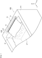
- Fig. 1 is a perspective view illustrating a water discharge device 10 in use according to the present embodiment.
- the water discharge device 10 is used in a bathtub device 200.
- the bathtub device 200 includes a bathtub 210 in addition to the water discharge device 10.
- a rim portion 215 of the bathtub 210 is provided with an installment surface 217.
- the water discharge device 10 includes a device main body 11 to be installed on the installment surface 217.
- the device main body 11 is formed into a laterally long flat shape.
- a laterally long discharged water flow W of a film shape is discharged forward from a water discharge port 13.
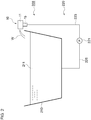
- Fig. 2 is a diagram of a configuration illustrating a water supply system 220 used in the water discharge device 10.
- the water supply system 220 includes a water supply pump 221 provided on an upstream side of the water discharge device 10.
- the water discharge device 10 includes water introducing portions 15 in addition to the device main body 11.
- the water supply pump 221 is connected to the water introducing portion 15 via a discharge side pipe 223 and is connected to the bathtub 210 that is a water supply source via a suction side pipe 225.
- the water supply pump 221 sucks bathtub water 211 in the bathtub 210 through the suction side pipe 225 and pressure-feeds water to the water introducing portion 15 through the discharge side pipe 223 by being driven.
- the water discharge device 10 discharges the water flow W from the device main body 11 when water is pressure-fed in the water introducing portion 15.
- Fig. 3 is a front view of the water discharge device 10.
- a front portion of the device main body 11 is provided with the laterally long water discharge port 13 of a slit shape.
- the plurality of water introducing portions 15 is provided in such a manner as to protrude downward from the device main body 11 while spaced in the lateral width direction of the water discharge port 13.
- a direction X a horizontal direction perpendicular thereto is referred to as a front-and-rear direction Y
- a up-and-down direction is referred to as a up-and-down direction Z.
- the direction X corresponds with a lateral width direction of the discharge passage 33, which will be described later.
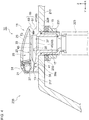
- Fig. 4 is a cross-sectional side view of the water discharge device 10. This is a cross-sectional view taken along a line A-A in Fig. 3 .
- the water introducing portion 15 is inserted in a through hole 229 formed on the installment surface 217.
- the water introducing portion 15 is formed with a water introducing passage 17 that supplies water to a downstream side at an inner portion thereof and is connected with the discharge side pipe 223 at a tip portion thereof.
- a portion of the water introducing portion 15 protruding on the opposite side to the installment surface 217 is attached with a fixing member 231 such as a nut by screwing or other means.
- the device main body 11 is fixed to the bathtub 210 by interposing the bathtub 210 with the fixing member 231.
- a seal ring 233 such as an O ring is interposed between the fixing member 231 and the bathtub 210.
- the device main body 11 is formed by a water discharge member 19 and an outer cover 21 assembled to each other.
- the water discharge member 19 includes a passage portion 23 formed with the water discharge port 13 at a front portion thereof, top surface portion 25 provided over the passage portion 23, and a lighting attachment portion 27 provided on a front upper surface of the passage portion 23.
- An upper surface of the top surface portion 25 is provided to be flush with an upper surface of the outer cover 21. These form an upper surface of the device main body 11.
- a hollow space 29 is provided between the top surface portion 25 and the passage portion 23.
- the lighting attachment portion 27 is attached with a lighting device 31.
- the lighting device 31 projects colored light or white light of a predetermined wavelength forward. This results in light projected to the discharged water flow W, a bather, or other objects, thereby providing preferable visual effects.
- the outer cover 21 is detachably attached to the front portion of the water discharge member 19.
- the outer cover 21 is provided in such a manner as to cover the lighting device 31 from above thereof and to cover both end portions 19a (see Fig. 3 ) in the lateral width direction X of the water discharge member 19 from the front thereof.
- the passage portion 23 is formed with the discharge passage 33 including the water discharge port 13 an inner portion thereof.
- the discharge passage 33 communicates the water introducing passage 17 on the upstream side to an external space 235 on the downstream side.
- the discharge passage 33 has a laterally long shape in a direction in which the water discharge port 13 extends and is formed by the water discharge port 13, a reservoir chamber 37, and a constricting flow path 39 (will be described later).
- a lower wall surface 71 of the discharge passage 33 is formed with a plurality of inlets 35 that feed water into the reservoir chamber 37. Water flows into the reservoir chamber 37 through the inlet 35 from the water introducing passage 17, which serves as an upstream side, and this water is temporary stored as reserve water.
- the reservoir chamber 37 is formed such that a pair of the lower wall surface 71 and an upper wall surface 73 of the discharge passage 33, which are opposite to each other in the up-and-down direction, spread in directions away from each other from an entrance 39a of the constricting flow path 39. Note that the lower wall surface 71 and the upper wall surface 73 are opposite to each other in the direction Z perpendicular to the lateral width direction X of the discharge passage 33.
- the constricting flow path 39 is provided at the downstream side of the reservoir chamber 37 and communicates the reservoir chamber 37 with the water discharge port 13.
- the constricting flow path 39 is formed such that the passage height, which is a space between the pair of the lower wall surface 71 and the upper wall surface 73, is smaller than that of the reservoir chamber 37.
- the constricting flow path 39 is formed to have substantially a constant passage height over a range from the entrance 39a to the water discharge port 13.
- the reserve water in the reservoir chamber 37 is fed to the water discharge port 13 through the constricting flow path 39.
- the reserve water is constricted while passing the constricting flow path 39 and thereby gains flow velocity. Therefore, the water flow W is vigorously discharged from the water discharge port 13.
- Fig. 5(a) is a plan view illustrating the discharge passage 33.
- Fig. 5(b) is a plan view of a spacer 69, which will be described later.
- Fig. 5(a) is also a plan views of a lower dividing member 51, which will be described later.
- the discharge passage 33 is formed to have a depth dimension smaller than a passage width in planar view.
- the discharge passage 33 is formed to be laterally long such that a cross-section thereof (not illustrated) has a passage width bigger than the passage height.
- Side wall surfaces 33a on both sides of the discharge passage 33 in the lateral width direction X are formed such that the passage width of the discharge passage 33 extends as approaching the water discharge port 13 side from a depth side of the reservoir chamber 37.
- the passage portion 23 includes a lower wall portion 41, an upper wall portion 43, a pair of side wall portions 45, and a rear wall portion 47 as illustrated in Fig. 4 and Fig. 5(a) .
- These inner wall surfaces define the discharge passage 33.
- the lower wall portion 41 and the upper wall portion 43 are provided to both sides of the discharge passage 33 in the up-and-down direction Z.
- the pair of side wall portions 45 are provided to the both sides of the discharge passage 33 in the lateral width direction X.
- the rear wall portion 47 is provided on the depth side of the discharge passage 33 opposite to the water discharge port 13.
- the pair of side wall portions 45 and the rear wall portion 47 are provided as a peripheral wall portion 49 surrounding the discharge passage 33 from the three directions of the both sides in the lateral width direction X and the depth side of the discharge passage 33.
- Fig. 6 is an exploded perspective view of the water discharge device 10.
- the water discharge member 19 is formed by the lower dividing member 51 as a first dividing member and an upper dividing member 53 as a second dividing member assembled to each other.
- the dividing members 51 and 53 are resin-molded products and have shapes divided into an upper part and a lower part, respectively, along the peripheral wall portion 49 of the water discharge member 19 as a boundary.
- Fig. 7(a) is a cross-sectional side view enlarging and illustrating the discharge passage 33.
- Fig. 7(b) is a diagram illustrating the dividing members 51 and 53 in an exploded state.
- the dividing members 51 and 53 have butting surfaces 55 opposite to each other in the up-and-down direction Z at boundary portions thereof.
- the butting surface 55 is provided in such a manner as to surround the discharge passage 33 from the three directions similarly to the peripheral wall portion 49.
- the dividing members 51 and 53 are assembled to each other while the butting surfaces 55 thereof are butted.
- the lower dividing member 51 has a first passage defining portion 57 that partially defines each of the reservoir chamber 37, the constricting flow path 39, and the water discharge port 13.
- the first passage defining portion 57 is formed by the lower wall surface 71 of the discharge passage 33 and a part of an inner peripheral wall surface 33b of the peripheral wall portion 49.
- the first passage defining portion 57 is formed into a recessed shape open upward within a range from a front end side to a depth side thereof.
- the upper dividing member 53 also has a second passage defining portion 59 that partially defines each of the reservoir chamber 37, the constricting flow path 39, and the water discharge port 13.
- the second passage defining portion 59 is formed by the upper wall surface 73 of the discharge passage 33 and a part of an inner peripheral wall surface 33b of the peripheral wall portion 49.
- the second passage defining portion 59 is formed into a convex shape protruding downward in a region S1 ranging from a front end side to an intermediate position thereof in the front-and-rear direction Y.
- the second passage defining portion 59 is further formed into a concave shape open downward in a region S2 ranging from the intermediate position in the front-and-rear direction Y to a depth side thereof.
- Each of the water discharge port 13, the reservoir chamber 37, and the constricting flow path 39 is defined by both of the first passage defining portion 57 and the second passage defining portion 59.
- the wall surfaces 71, 73, and 33b that are inner wall surfaces of the discharge passage 33 are exposed to the external space 235.
- the lower wall surface 71 of the lower dividing member 51 and the upper wall surface 73 of the upper dividing member 53 are exposed to face the external space 235.
- the spacers 69 served as a columnar body are disposed as illustrated in Fig. 5(a) and Fig. 6 .
- the plurality of spacers 69 is disposed with intervals in the lateral width direction X.
- An outer peripheral surface 69a of the spacer 69 is formed into a round shape in planar view as illustrated in Fig. 5(b) .
- the outer peripheral surface 69a of the spacer 69 is formed to have a streamlined shape with respect to a water flow flowing in the discharge passage 33.
- an upstream side portion 69b thereof is formed to have a lateral width gradually increasing as approaching the downstream side (lower side in the drawing) of a water flow flowing in the discharge passage 33 while a downstream side portion 69c thereof is formed to have a lateral width gradually decreasing as approaching the downstream side.
- Fig. 8 is a cross-sectional view taken along a line B-B in Fig. 3 .
- the shape of the lower dividing member 51 illustrated in the drawing corresponds to a cross-section taken along line C-C in Fig. 5(a) .
- the spacer 69 rises from the lower wall surface 71 of the lower dividing member 51, and an upper surface thereof contacts with the upper wall surface 73 of the upper dividing member 53. This allows the spacer 69 to maintain the space between the upper wall surface 73 and the lower wall surface 71 of the discharge passage 33 opposite to each other in the up-and-down direction.
- the water discharge member 19 has a positioning structure 79 formed by a positioning recessed portion 75 and a positioning protruding portion 77 as illustrated in Fig. 3 .
- the positioning structure 79 is provided to the both end portions 19a of the water discharge member 19 in the lateral width direction X.
- Fig. 9(a) is a diagram illustrating a part of a cross-section taken along a line D-D in Fig. 3 .
- Fig. 9(b) is a diagram illustrating the dividing members 51 and 53 in an exploded state. The shape of the lower dividing member 51 illustrated in the drawing corresponds to a cross-section taken along line E-E in Fig. 5(a) .
- the positioning recessed portion 75 is formed as a bottomed hole open to the butting surface 55 of the lower dividing member 51.
- the positioning protruding portion 77 is provided to the upper dividing member 53 at a position corresponding to the positioning recessed portion 75 and is formed as a boss protruding from the butting surface 55 thereof.
- the lower dividing member 51 is provided with a plurality of accommodation portions 83 that accommodate a fixing tool 81 such as a screw at a portion corresponding to the peripheral wall portion 49 as illustrated in Fig. 8 .
- the spacer 69 of the lower dividing member 51 is also provided with an accommodation portion 83 that accommodates a fixing tool 81.
- Each of the accommodation portions 83 is formed with an insertion hole 85 to be inserted with the fixing tool 81.
- the upper dividing member 53 is provided with a screw hole as an attached portion 87 at a position corresponding to the insertion hole 85.
- a tip portion 81a of the fixing tool 81 is fastened to the attached portion 87 by screwing thereto.
- the dividing members 51 and 53 are detachably coupled by these fixing tools 81.
- the accommodation portion 83 of the lower dividing member 51 includes those provided coaxially to the positioning recessed portion 75 as illustrated in Fig. 9(a) .
- the attached portion 87 of the upper dividing member 53 corresponding to the insertion hole 85 of the accommodation portion 83 is provided to the positioning protruding portion 77.
- the lower dividing member 51 and the upper dividing member 53 have a first seal member 89 interposed between the multiple butting surfaces 55 as illustrated in Fig. 8 .
- the butting surface 55 of the lower dividing member 51 is formed with a groove portion 91 to which the first seal member 89 can be fitted.
- the first seal member 89 is disposed inside the groove portion 91.
- the first seal member 89 is disposed in the groove portion 91 in a freely detachable manner without bonded thereto.
- the first seal member 89 is formed in such a manner as to extend along the inner peripheral wall surface 33b of the peripheral wall portion 49 of the discharge passage 33.
- the inner peripheral wall surface 33b extends from one opening edge 13a of the water discharge port 13 in the lateral width direction to the other opening edge 13a as illustrated in Fig. 5(a) .
- the first seal member 89 is disposed to surround the discharge passage 33 from the three directions of the both sides in the lateral width direction and the depth side.
- the butting surface 55 of the upper dividing member 53 is formed with a convex portion 93 at a position opposite to the first seal member 89 in the up-and-down direction Z.
- the convex portion 93 is formed as a convex strip along the direction in which the first seal member 89 extends.
- the convex portion 93 presses the first seal member 89 and the plurality of butting surfaces 55 is sealed by the first seal member 89. This allows the first seal member 89 to regulate leakage of water in the discharge passage 33 from between the butting surfaces 55 to the outside. More specifically, leakage from an outer peripheral surface 19c of the water discharge member 19 from between the butting surfaces 55 or leakage from the insertion hole 85 or other parts of the accommodation portion 83 is regulated.
- a second seal member 95 of a ring shape is interposed between a tip end surface 69d of the spacer 69 and an upper wall surface 73 of the upper dividing member 53 opposite thereto.
- the second seal member 95 is disposed in an annular groove portion 97 formed on the tip end surface 69d also in a freely detachable manner without bonded thereto similarly to the first seal member 89.
- the upper wall surface 73 is formed with a convex portion 99 of a ring shape at a position opposite to the second seal member 95 in the up-and-down direction Z. The convex portion 99 presses the second seal member 95 and the tip end surface 69d and the upper wall surface 73 are sealed by the second seal member 95.
- the plurality of insertion holes 85 is disposed with intervals along the inner peripheral wall surface 33b of the peripheral wall portion 49 of the water discharge member 19 as illustrated in Fig. 5(a) . That is, the plurality of fixing tools 81 is also disposed with similar positional relation although not illustrated in the drawing. These fixing tools 81 next to each other in the lateral width direction X are disposed such that an interval L2 in the both end portions 19a in the lateral width direction X of the water discharge member 19 is narrower than an interval L1 in an intermediate portion 19b in the lateral width direction X of the water discharge member 19.
- water of a predetermined flow rate is pressure-fed from the water supply pump 221 (see Fig. 2 ) as illustrated in Fig. 4 and this water flows into the reservoir chamber 37 from the inlet 35 through the water introducing passage 17 and is then temporary stored in the reservoir chamber 37 as reserve water. Feeding water from the inlet 35 while reserve water is stored in the reservoir chamber 37 pressures the reserve water in the reservoir chamber 37. This water pressure causes the reserve water to be fed to the water discharge port 13 through the constricting flow path 39 and the water flow W is discharged from the water discharge port 13.
- water flowing from the inlet 35 which serves as an upstream side flows, in a spreading manner from the inlet 35 toward the entrance 39a of the constricting flow path 39.
- the flow velocity of this water flow is radically decreased when passing the reservoir chamber 37 than in the case where the discharge passage 33 has a constant passage height.
- the water flow is effectively straightened such that the flow velocity becomes uniform in the lateral width direction X of the discharge passage 33 during the time the water flow reaches the entrance 39a of the constricting flow path 39 from the inlet 35.
- each of the water discharge port 13, the reservoir chamber 37, and the constricting flow path 39 is defined by both of the upper dividing member 53 and the lower dividing member 51. Therefore, the inner wall surfaces 71, 73, and 33b of the discharge passage 33 can be exposed to the external space 235 over an area ranging from the water discharge port 13 to the reservoir chamber 37 when the respective dividing members 51 and 53 are exploded.
- a degree of difficulty in molding is generally lower in the case of a plurality of components separately molded for exposing inner wall surfaces thereof to the external space than in the case of a single component integrally molded. This also facilitates ensuring accuracy in dimensions of the inner wall surfaces thereof.
- the water discharge member 19 facilitates suppression of roughness of the inner wall surfaces 71, 73, and 33b of the discharge passage 33, thereby facilitating suppression of disturbance in the shape of the discharged water flow W caused by the surface roughness.
- the dividing members 51 and 53 are resin-molded products and thus a casting surface such as in a metal casting product is not generated on the inner wall surfaces 71, 73, and 33b of the discharge passage 33 and surface roughness can be greatly suppressed.
- a water flow supplied to the discharge passage 33 is prone to be disturbed due to a radical change in a flow passage cross section when the water flow flows therein from the inlet 35.
- the discharge passage 33 has a cross-sectional shape with a wide passage width and a low passage height for vigorously discharging the laterally long water flow W. Therefore a water flow flowing inside the discharge passage 33 also has a laterally long and thin shape and thus is prone to influence of a disturbed flow, a clogged foreign matter, or others in the discharge passage 33. And a distance from the inlet 35 to the water discharge port 13 varies depending on a position in the lateral width direction of the water discharge port 13.
- the water discharge member 19 is formed with the reservoir chamber 37 in the discharge passage 33 and thus the flow velocity of a water flow in the discharge passage 33 decreases when the water flow passes the reservoir chamber 37. This results in uniforming a flow velocity in the lateral width direction X in the reservoir chamber 37, thereby allowing for effectively straightening the flow.
- the water flow W discharged from the water discharge port 13 is thus facilitated to uniform a flow velocity in the lateral width direction X. Suppressing disturbance in the shape allows for providing the discharged water flow W with excellent appearance.
- the discharged water flow W having excellent appearance further provides relaxing effects by falling onto a shoulder of a bather or more.
- the reservoir chamber 37 is formed such that a pair of the lower wall surface 71 and the upper wall surface 73 of the discharge passage 33, which are opposite to each other, extend in directions away from each other from the entrance 39a of the constricting flow path 39. Therefore, the volume of an interior portion of the reservoir chamber 37 can be easily increased as compared to a case where only one of the pair of wall surfaces 71 and 73 is formed to extend away from the other. As a result, the water pressure of reserve water in the reservoir chamber 37 is lowered and thus the flow velocity thereof can be easily lowered. This allows for effectively straightening a flow in the reservoir chamber 37 in such a manner as to uniform a flow velocity in the lateral width direction X.
- the water discharge member 19 further has the following advantages due to the spacer 69 disposed in the discharge passage 33 as illustrated in Fig. 8 .
- the water discharge device 10 may be used in a case where a pillow member is disposed on an upper surface of the device main body 11, and a bather places the head thereon.
- the water discharge member 19 is applied with a load to narrow the space in the discharge passage 33.
- the shape of the discharged water flow W may be disadvantageously disturbed.
- a water flow flowing in the discharge passage 33 is prone to influence of a change in the space in the discharge passage 33 due to the laterally long and thin shape as described above.
- the space in the discharge passage 33 can be maintained by the spacers 69 in the present embodiment and thus, even when the aforementioned load is applied to the water discharge member 19, disturbance in the shape of the discharged water flow W can be easily suppressed.
- the dividing members 51 and 53 are resin-molded products that are difficult to ensure strength, a change of the space in the discharge passage 33 due to the load can be suppressed even in this case.
- Disposing the spacers 69 in the discharge passage 33 results in division of water flows by the spacers 69.
- the spacers 69 according to the present embodiment are disposed in the reservoir chamber 37 where the flow velocity of a water flow is slow and a distance to the water discharge port 13 is farther than the constricting flow path 39. Therefore, even when a water flow is divided by the spacer 69, the divided water flows are facilitated to join at an early stage before reaching the water discharge port 13, thereby facilitating suppression of disturbance in the shape of a discharged water flow W caused by divided water flows.
- the first seal member 89 is attached to the upper dividing member 53 without bonded thereto, the first seal member 89 is easily detached upon assembling the dividing members 51 and 53. If attached by bonding, the assembling work becomes laborious.
- the first seal member 89 according to the present embodiment has such a complicated shape to surround the discharge passage 33 from the three directions and thus attaching to the upper dividing member 53 by bonding makes the assembling work further laborious.
- the first seal member 89 according to the present embodiment is installed in the groove portion 91 of the lower dividing member 51 and thus the upper dividing member 53 can be assembled to the lower dividing member 51 with a state where the first seal member 89 is mounted in the groove portion 91 without bonded thereto, thereby enhancing workability upon assembling.
- the water discharge member 19 has the depth dimension smaller than the lateral width dimension as illustrated in Fig. 5(a) for discharging the water flow W having a wide lateral width while reducing a space occupied thereby.
- the plurality of fixing tools 81 (not illustrated in the drawing) is disposed such that the interval L2 in the both end portions 19a of the water discharge member 19 is narrower than the interval L1 in the intermediate portion 19b in the present embodiment. Therefore, a degree of fixture of the both end portions 19a is higher than that of the intermediate portion 19b.
- the interval L1 between the fixing tools 81 can be wide and the number of the fixing tools 81 can be reduced in the intermediate portion 19b of the water discharge member 19 while in the both end portions 19a thereof the interval L2 between the fixing tools 81 can be narrower to effectively resist the bending moment. This allows for stably maintaining the state where the dividing members 51 and 53 are coupled to each other.
- the dividing members 51 and 53 are resin-molded products and thus mixing a coloring agent in the resin composition allows for providing the water discharge device 10 in a various color variations. Furthermore, the dividing members 51 and 53 are resin-molded products and thus post-processing such as anti-corrosion treatment is unnecessary, thereby enhancing productivity.
- the example where a base body to which the water discharge device 10 is installed is the bathtub 210 has been described; however, a specific structure of the base body is not limited thereto.
- the water discharge device 10 may be installed to a washbasin in a lavatory, a sink in a kitchen, or other items serving as the base body. In either case, an installment surface 217 may be provided to the base body and the water discharge device 10 may be installed on the installment surface 217.
- the water discharge port 13 is formed into a laterally long slit shape.
- the discharge passage 33 is formed to be laterally long in a direction in which the water discharge port 13 extends.
- the shapes are not limited thereto and may be formed into a round shape for example or other shapes.
- the passage portion 23 having a hollow cross section is formed by assembling the plurality of components and thus, even in this case, disassembled components allows for easily reducing surface roughness by post-processing such as cutting or polishing of the inner wall surface of the discharge passage 33.
- the upper dividing member 53 and the lower dividing member 51 have been described as being the first dividing member and the second dividing member, respectively, having shapes of the water discharge member 19 divided into an upper part and a lower part, respectively. These members may have shapes divided in the lateral width direction X. In either case, the dividing members are only required to have shapes divided in a direction intersecting with the direction from the reservoir chamber 37 toward the water discharge port 13.
- the lower dividing member 51 and the upper dividing member 53 are detachably assembled to each other by the fixing tools 81; however, the lower dividing member 51 and the upper dividing member 53 may be assembled by snap fitting or other means without limited thereto.
- the inlet 35 is formed on the lower wall surface 71 of the discharge passage 33; however, the inlet 35 is only required to be formed on the wall surface of the discharge passage 33 and may be formed on the upper wall surface 73, a rear wall surface, or the side wall surface.
- the spacer 69 is integrally formed in a rising manner from the lower dividing member 51; however, the spacer 69 may be integrally formed with the upper dividing member 53 or may be provided separately from the dividing members 51 and 53.
- the positioning structure 79 is formed by a combination of the positioning protruding portion 77 and the positioning recessed portion 75 has been described; however, the positioning structure 79 is not limited thereto.
- the positioning structure 79 may be provided to one of the lower dividing member 51 and the upper dividing member 53 for example or may be formed by a guiding protruding portion protruding toward the other. In this case, the other one of the dividing members 51 and 53 is guided by the guiding protruding portion upon assembling the dividing members 51 and 53, thereby performing positioning thereof.
- the positioning protruding portion 77 is provided to the upper dividing member 53 while the positioning recessed portion 75 is provided to the lower dividing member 51 in the positioning structure 79 has been described; however, the positioning recessed portion 75 may be provided to the upper dividing member 53 while the positioning protruding portion 77 may be provided to the lower dividing member 51.
- the fixing tool 81 is accommodated in the accommodation portion 83 provided on the lower dividing member 51 ; however, the fixing tool 81 may be accommodated in an accommodation portion 83 provided on the upper dividing member 53.
- the accommodation portion 83 is provided on one of the lower dividing member 51 and the upper dividing member 53 at a portion corresponding the peripheral wall portion 49 surrounding the discharge passage 33 while the attached portion 87 is provided on the other.
- the present invention relates to a water discharge device that discharges water.
Landscapes
- Health & Medical Sciences (AREA)
- Public Health (AREA)
- Epidemiology (AREA)
- General Health & Medical Sciences (AREA)
- Life Sciences & Earth Sciences (AREA)
- Engineering & Computer Science (AREA)
- Hydrology & Water Resources (AREA)
- Water Supply & Treatment (AREA)
- Bathtubs, Showers, And Their Attachments (AREA)
- Nozzles (AREA)
- Domestic Plumbing Installations (AREA)
Abstract
Description
- The present invention relates to a water discharge device for discharging water and a bathtub device including the water discharge device.
- In the related art, a water discharge device that discharges a water flow of a film shape is known (e.g. see patent document 1). This is installed on a bathtub and a water flow is discharged from a water discharge port. A discharged water flow of a film shape falling like a waterfall has excellent appearance and also provides relaxing effects such as by falling onto a shoulder of a bather.
- [patent document 1]
JP 4066459 B2 - In the water discharge device of
patent document 1, a water passage that leads water to the water discharge port is formed inside a device main body and the water passage of the device main body is formed by a single component. The device main body is considered to be integrally molded by a metal casting product. When a portion having a hollow cross section is integrally molded by a single component, generally it is difficult to ensure accuracy in dimensions of the inner wall surface thereof and thus roughness of the inner wall surface tends to be high. Especially when the device main body is integrally molded by a metal casting product, an inner wall surface thereof is the casting surface and thus the surface tends to be more roughly. A rough surface tends to cause disturbance in a water flow flowing in the water passage. Disturbance in the shape of a discharged water flow may disadvantageously deteriorate excellent appearance. - The present invention has been devised in consideration to such disadvantages with an object to provide technique capable of suppressing disturbance in the shape of a discharged water flow.
- In order to solve the above disadvantage, a water discharge device of an aspect of the present invention is comprising: a water discharge member formed with a discharge passage at an inner portion thereof, wherein the discharge passage comprises: a water discharge port for discharging water; a reservoir chamber for storing water flowing therein from an upstream side; and a constricting flow path for feeding water in the reservoir chamber to the water discharge port, the water discharge member is formed by a first dividing member and a second dividing member assembled to each other, and each of the water discharge port, the reservoir chamber, and the constricting flow path is defined by both of the first dividing member and the second dividing member.
- According to this aspect, inner wall surfaces of the discharge passage can be exposed to an external space over an area ranging from the water discharge port to the reservoir chamber when the respective dividing members are exploded. Upon forming a portion having a hollow cross section, a degree of difficulty in molding is generally lower in the case of a plurality of components separately molded to expose inner wall surfaces thereof to the external space than in the case of a single component integrally molded. This also facilitates ensuring accuracy in dimensions of the inner wall surfaces thereof. This facilitates suppression of roughness of the inner wall surfaces of the discharge passage and disturbance in the shape of a discharged water flow caused by the surface roughness.
- The reservoir chamber may be formed such that a pair of wall surfaces of the discharge passage, which are opposite to each other, spread in directions away from each other from an entrance of the constricting flow path.
- According to this aspect, the water pressure in the reservoir chamber is lowered and thus the flow velocity of water can be easily lowered. This allows for effectively straightening a flow in the reservoir chamber in such a manner as to uniform a flow velocity.
- The water discharge member may further comprise a spacer that is disposed inside the discharge passage and maintains a space between the pair of wall surfaces of the discharge passage opposite to each other.
- According to this aspect, even when such a load to narrow the space in the discharge passage is applied to the water discharge member, this space can be maintained, thereby facilitating suppression of disturbance in the shape of a discharged water flow.
- The spacer may be disposed in the reservoir chamber.
- According to this aspect, even when a water flow is divided by the spacer, the divided water flows are facilitated to join at an early stage before reaching the water discharge port, thereby facilitating suppression of disturbance in the shape of a discharged water flow caused by divided water flows.
- The first dividing member and the second dividing member may include a plurality of butting surfaces butted to each other and a seal member that is interposed between the multiple butting surfaces and seals between the plurality of butting surfaces.
- This aspect allows for regulating leakage of water in the discharge passage from between the butting surfaces to the outside.
- The first dividing member and the second dividing member may be an upper dividing member and a lower dividing member, respectively, having shapes of the water discharge member divided into an upper part and a lower part, respectively. The plurality of butting surfaces may be provided opposite to each other in a up-and-down direction and the seal member may be disposed in a groove portion formed on the butting surface of the lower dividing member.
- According to this aspect, the upper dividing member can be assembled to the lower dividing member in a state where the seal member is mounted in the groove portion without bonded thereto, thereby enhancing workability upon assembling.
- The water discharge member may have a positioning structure that positions the first dividing member and the second dividing member upon assembling the first dividing member and the second dividing member.
- This aspect facilitates positioning of the dividing members upon assembling the dividing members, thereby enhancing workability upon assembling.
- The water discharge member may have a peripheral wall portion surrounding the discharge passage from three directions of both sides in a lateral width direction of the discharge passage and a depth side opposite to the water discharge port. The first dividing member and the second dividing member may be coupled by a plurality of fixing tools disposed with intervals along an inner peripheral wall surface of the peripheral wall portion. The plurality of fixing tools may be disposed such that an interval in an intermediate portion in a lateral width direction of the water discharge member is narrower than an interval in both end portions thereof.
- According to this aspect, the interval between the fixing tools can be wide and the number of the fixing tools can be reduced in the intermediate portion of the water discharge member while in the both end portions thereof the interval between the fixing tools can be narrower to effectively resist bending moment. This allows for stably maintaining the state where the dividing members are coupled to each other.
- The first dividing member and the second dividing member may be a resin-molded product.
- According to this aspect, a casting surface such as in a metal casting product is not generated on the inner wall surface of the discharge passage and surface roughness can be greatly suppressed as compared to a metal casting product.
- The water discharge port may be formed into a laterally long slit shape. The discharge passage may be formed to be laterally long in a direction in which the water discharge port extends.
- Another aspect of the present invention relates to a bathtub device. A bathtub device comprises the water discharge device of the aspect described above and a bathtub installed with the water discharge device.
- According to the present invention, disturbance in the shape of a discharged water flow can be suppressed.
-
-
Fig. 1 is a perspective view illustrating a water discharge device in use according to an embodiment. -
Fig. 2 is a diagram of a configuration illustrating a water supply system used in the water discharge device according to the embodiment. -
Fig. 3 is a front view of the water discharge device according to the embodiment. -
Fig. 4 is a cross-sectional view taken along a line A-A inFig. 3 . -
Fig. 5(a) is a plan view illustrating a discharge passage of a water discharge member according to the embodiment.Fig. 5(b) is a plan view illustrating a spacer. -
Fig. 6 is an exploded perspective view of the water discharge device according to the embodiment. -
Fig. 7(a) is a cross-sectional side view illustrating the discharge passage of the water discharge member according to the embodiment.Fig. 7(b) is a diagram illustrating an upper dividing member and a lower dividing member in an exploded state. -
Fig. 8 is a cross-sectional view taken along a line B-B inFig. 3 . -
Fig. 9(a) is a cross-sectional view taken along a line D-D inFig. 3 .Fig. 9(b) is a diagram illustrating the upper dividing member and the lower dividing member in an exploded state. -
Fig. 1 is a perspective view illustrating awater discharge device 10 in use according to the present embodiment. - The
water discharge device 10 is used in abathtub device 200. Thebathtub device 200 includes abathtub 210 in addition to thewater discharge device 10. Arim portion 215 of thebathtub 210 is provided with aninstallment surface 217. Thewater discharge device 10 includes a devicemain body 11 to be installed on theinstallment surface 217. The devicemain body 11 is formed into a laterally long flat shape. A laterally long discharged water flow W of a film shape is discharged forward from awater discharge port 13. -
Fig. 2 is a diagram of a configuration illustrating awater supply system 220 used in thewater discharge device 10. - The
water supply system 220 includes awater supply pump 221 provided on an upstream side of thewater discharge device 10. Thewater discharge device 10 includeswater introducing portions 15 in addition to the devicemain body 11. Thewater supply pump 221 is connected to thewater introducing portion 15 via adischarge side pipe 223 and is connected to thebathtub 210 that is a water supply source via asuction side pipe 225. Thewater supply pump 221 sucksbathtub water 211 in thebathtub 210 through thesuction side pipe 225 and pressure-feeds water to thewater introducing portion 15 through thedischarge side pipe 223 by being driven. Thewater discharge device 10 discharges the water flow W from the devicemain body 11 when water is pressure-fed in thewater introducing portion 15. -
Fig. 3 is a front view of thewater discharge device 10. - A front portion of the device
main body 11 is provided with the laterally longwater discharge port 13 of a slit shape. The plurality ofwater introducing portions 15 is provided in such a manner as to protrude downward from the devicemain body 11 while spaced in the lateral width direction of thewater discharge port 13. Note that in the descriptions below the lateral width direction of thewater discharge port 13 is referred to as a direction X, a horizontal direction perpendicular thereto is referred to as a front-and-rear direction Y, and a up-and-down direction is referred to as a up-and-down direction Z. The direction X corresponds with a lateral width direction of thedischarge passage 33, which will be described later. -
Fig. 4 is a cross-sectional side view of thewater discharge device 10. This is a cross-sectional view taken along a line A-A inFig. 3 . - The
water introducing portion 15 is inserted in a throughhole 229 formed on theinstallment surface 217. Thewater introducing portion 15 is formed with awater introducing passage 17 that supplies water to a downstream side at an inner portion thereof and is connected with thedischarge side pipe 223 at a tip portion thereof. A portion of thewater introducing portion 15 protruding on the opposite side to theinstallment surface 217 is attached with a fixingmember 231 such as a nut by screwing or other means. The devicemain body 11 is fixed to thebathtub 210 by interposing thebathtub 210 with the fixingmember 231. Note that aseal ring 233 such as an O ring is interposed between the fixingmember 231 and thebathtub 210. - The device
main body 11 is formed by awater discharge member 19 and anouter cover 21 assembled to each other. Thewater discharge member 19 includes apassage portion 23 formed with thewater discharge port 13 at a front portion thereof,top surface portion 25 provided over thepassage portion 23, and alighting attachment portion 27 provided on a front upper surface of thepassage portion 23. An upper surface of thetop surface portion 25 is provided to be flush with an upper surface of theouter cover 21. These form an upper surface of the devicemain body 11. Ahollow space 29 is provided between thetop surface portion 25 and thepassage portion 23. Thelighting attachment portion 27 is attached with alighting device 31. Thelighting device 31 projects colored light or white light of a predetermined wavelength forward. This results in light projected to the discharged water flow W, a bather, or other objects, thereby providing preferable visual effects. - The
outer cover 21 is detachably attached to the front portion of thewater discharge member 19. Theouter cover 21 is provided in such a manner as to cover thelighting device 31 from above thereof and to cover bothend portions 19a (seeFig. 3 ) in the lateral width direction X of thewater discharge member 19 from the front thereof. - The
passage portion 23 is formed with thedischarge passage 33 including thewater discharge port 13 an inner portion thereof. Thedischarge passage 33 communicates thewater introducing passage 17 on the upstream side to anexternal space 235 on the downstream side. Thedischarge passage 33 has a laterally long shape in a direction in which thewater discharge port 13 extends and is formed by thewater discharge port 13, areservoir chamber 37, and a constricting flow path 39 (will be described later). - A
lower wall surface 71 of thedischarge passage 33 is formed with a plurality ofinlets 35 that feed water into thereservoir chamber 37. Water flows into thereservoir chamber 37 through theinlet 35 from thewater introducing passage 17, which serves as an upstream side, and this water is temporary stored as reserve water. Thereservoir chamber 37 is formed such that a pair of thelower wall surface 71 and anupper wall surface 73 of thedischarge passage 33, which are opposite to each other in the up-and-down direction, spread in directions away from each other from anentrance 39a of the constrictingflow path 39. Note that thelower wall surface 71 and theupper wall surface 73 are opposite to each other in the direction Z perpendicular to the lateral width direction X of thedischarge passage 33. - The constricting
flow path 39 is provided at the downstream side of thereservoir chamber 37 and communicates thereservoir chamber 37 with thewater discharge port 13. The constrictingflow path 39 is formed such that the passage height, which is a space between the pair of thelower wall surface 71 and theupper wall surface 73, is smaller than that of thereservoir chamber 37. The constrictingflow path 39 is formed to have substantially a constant passage height over a range from theentrance 39a to thewater discharge port 13. The reserve water in thereservoir chamber 37 is fed to thewater discharge port 13 through the constrictingflow path 39. The reserve water is constricted while passing the constrictingflow path 39 and thereby gains flow velocity. Therefore, the water flow W is vigorously discharged from thewater discharge port 13. -
Fig. 5(a) is a plan view illustrating thedischarge passage 33.Fig. 5(b) is a plan view of aspacer 69, which will be described later.Fig. 5(a) is also a plan views of alower dividing member 51, which will be described later. - When a dimension in the lateral width direction X and the front-and-rear direction Y of the
discharge passage 33 are regarded as the passage width and the depth dimension, respectively, thedischarge passage 33 is formed to have a depth dimension smaller than a passage width in planar view. Thedischarge passage 33 is formed to be laterally long such that a cross-section thereof (not illustrated) has a passage width bigger than the passage height. Side wall surfaces 33a on both sides of thedischarge passage 33 in the lateral width direction X are formed such that the passage width of thedischarge passage 33 extends as approaching thewater discharge port 13 side from a depth side of thereservoir chamber 37. - The
passage portion 23 includes alower wall portion 41, anupper wall portion 43, a pair ofside wall portions 45, and arear wall portion 47 as illustrated inFig. 4 andFig. 5(a) . These inner wall surfaces define thedischarge passage 33. Thelower wall portion 41 and theupper wall portion 43 are provided to both sides of thedischarge passage 33 in the up-and-down direction Z. The pair ofside wall portions 45 are provided to the both sides of thedischarge passage 33 in the lateral width direction X. Therear wall portion 47 is provided on the depth side of thedischarge passage 33 opposite to thewater discharge port 13. The pair ofside wall portions 45 and therear wall portion 47 are provided as aperipheral wall portion 49 surrounding thedischarge passage 33 from the three directions of the both sides in the lateral width direction X and the depth side of thedischarge passage 33. -
Fig. 6 is an exploded perspective view of thewater discharge device 10. - The
water discharge member 19 is formed by thelower dividing member 51 as a first dividing member and anupper dividing member 53 as a second dividing member assembled to each other. The dividingmembers peripheral wall portion 49 of thewater discharge member 19 as a boundary. -
Fig. 7(a) is a cross-sectional side view enlarging and illustrating thedischarge passage 33.Fig. 7(b) is a diagram illustrating the dividingmembers - The dividing
members surfaces 55 opposite to each other in the up-and-down direction Z at boundary portions thereof. The buttingsurface 55 is provided in such a manner as to surround thedischarge passage 33 from the three directions similarly to theperipheral wall portion 49. The dividingmembers - The
lower dividing member 51 has a firstpassage defining portion 57 that partially defines each of thereservoir chamber 37, the constrictingflow path 39, and thewater discharge port 13. The firstpassage defining portion 57 is formed by thelower wall surface 71 of thedischarge passage 33 and a part of an innerperipheral wall surface 33b of theperipheral wall portion 49. The firstpassage defining portion 57 is formed into a recessed shape open upward within a range from a front end side to a depth side thereof. Theupper dividing member 53 also has a secondpassage defining portion 59 that partially defines each of thereservoir chamber 37, the constrictingflow path 39, and thewater discharge port 13. The secondpassage defining portion 59 is formed by theupper wall surface 73 of thedischarge passage 33 and a part of an innerperipheral wall surface 33b of theperipheral wall portion 49. The secondpassage defining portion 59 is formed into a convex shape protruding downward in a region S1 ranging from a front end side to an intermediate position thereof in the front-and-rear direction Y. The secondpassage defining portion 59 is further formed into a concave shape open downward in a region S2 ranging from the intermediate position in the front-and-rear direction Y to a depth side thereof. Each of thewater discharge port 13, thereservoir chamber 37, and the constrictingflow path 39 is defined by both of the firstpassage defining portion 57 and the secondpassage defining portion 59. - When the dividing
members discharge passage 33 are exposed to theexternal space 235. Here thelower wall surface 71 of thelower dividing member 51 and theupper wall surface 73 of the upper dividingmember 53 are exposed to face theexternal space 235. - Inside the
reservoir chamber 37 of thedischarge passage 33, thespacers 69 served as a columnar body are disposed as illustrated inFig. 5(a) andFig. 6 . The plurality ofspacers 69 is disposed with intervals in the lateral width direction X. - An outer
peripheral surface 69a of thespacer 69 is formed into a round shape in planar view as illustrated inFig. 5(b) . In other words, the outerperipheral surface 69a of thespacer 69 is formed to have a streamlined shape with respect to a water flow flowing in thedischarge passage 33. Specifically, anupstream side portion 69b thereof is formed to have a lateral width gradually increasing as approaching the downstream side (lower side in the drawing) of a water flow flowing in thedischarge passage 33 while adownstream side portion 69c thereof is formed to have a lateral width gradually decreasing as approaching the downstream side. -
Fig. 8 is a cross-sectional view taken along a line B-B inFig. 3 . The shape of thelower dividing member 51 illustrated in the drawing corresponds to a cross-section taken along line C-C inFig. 5(a) . - The
spacer 69 rises from thelower wall surface 71 of thelower dividing member 51, and an upper surface thereof contacts with theupper wall surface 73 of the upper dividingmember 53. This allows thespacer 69 to maintain the space between theupper wall surface 73 and thelower wall surface 71 of thedischarge passage 33 opposite to each other in the up-and-down direction. - The
water discharge member 19 has apositioning structure 79 formed by a positioning recessedportion 75 and apositioning protruding portion 77 as illustrated inFig. 3 . Thepositioning structure 79 is provided to the bothend portions 19a of thewater discharge member 19 in the lateral width direction X. -
Fig. 9(a) is a diagram illustrating a part of a cross-section taken along a line D-D inFig. 3 .Fig. 9(b) is a diagram illustrating the dividingmembers lower dividing member 51 illustrated in the drawing corresponds to a cross-section taken along line E-E inFig. 5(a) . - The positioning recessed
portion 75 is formed as a bottomed hole open to the buttingsurface 55 of thelower dividing member 51. Thepositioning protruding portion 77 is provided to the upper dividingmember 53 at a position corresponding to the positioning recessedportion 75 and is formed as a boss protruding from the buttingsurface 55 thereof. - When the
lower dividing member 51 and the upper dividingmember 53 are assembled to each other, a worker positions the dividingmembers Fig. 9(b) and thereby the plurality of positioning recessedportions 75 is inserted with the correspondingpositioning protruding portions 77. This facilitates positioning of the dividingmembers members - The
lower dividing member 51 is provided with a plurality ofaccommodation portions 83 that accommodate a fixingtool 81 such as a screw at a portion corresponding to theperipheral wall portion 49 as illustrated inFig. 8 . Thespacer 69 of thelower dividing member 51 is also provided with anaccommodation portion 83 that accommodates a fixingtool 81. Each of theaccommodation portions 83 is formed with aninsertion hole 85 to be inserted with the fixingtool 81. Theupper dividing member 53 is provided with a screw hole as an attachedportion 87 at a position corresponding to theinsertion hole 85. Atip portion 81a of the fixingtool 81 is fastened to the attachedportion 87 by screwing thereto. The dividingmembers tools 81. - The
accommodation portion 83 of thelower dividing member 51 includes those provided coaxially to the positioning recessedportion 75 as illustrated inFig. 9(a) . The attachedportion 87 of the upper dividingmember 53 corresponding to theinsertion hole 85 of theaccommodation portion 83 is provided to thepositioning protruding portion 77. - The
lower dividing member 51 and the upper dividingmember 53 have afirst seal member 89 interposed between the multiple butting surfaces 55 as illustrated inFig. 8 . The buttingsurface 55 of thelower dividing member 51 is formed with agroove portion 91 to which thefirst seal member 89 can be fitted. Thefirst seal member 89 is disposed inside thegroove portion 91. Thefirst seal member 89 is disposed in thegroove portion 91 in a freely detachable manner without bonded thereto. - The
first seal member 89 is formed in such a manner as to extend along the innerperipheral wall surface 33b of theperipheral wall portion 49 of thedischarge passage 33. The innerperipheral wall surface 33b extends from oneopening edge 13a of thewater discharge port 13 in the lateral width direction to the other openingedge 13a as illustrated inFig. 5(a) . Thefirst seal member 89 is disposed to surround thedischarge passage 33 from the three directions of the both sides in the lateral width direction and the depth side. - Referring back to
Fig. 8 , the buttingsurface 55 of the upper dividingmember 53 is formed with aconvex portion 93 at a position opposite to thefirst seal member 89 in the up-and-down direction Z. Theconvex portion 93 is formed as a convex strip along the direction in which thefirst seal member 89 extends. Theconvex portion 93 presses thefirst seal member 89 and the plurality of buttingsurfaces 55 is sealed by thefirst seal member 89. This allows thefirst seal member 89 to regulate leakage of water in thedischarge passage 33 from between the butting surfaces 55 to the outside. More specifically, leakage from an outerperipheral surface 19c of thewater discharge member 19 from between the butting surfaces 55 or leakage from theinsertion hole 85 or other parts of theaccommodation portion 83 is regulated. - Note that a
second seal member 95 of a ring shape is interposed between atip end surface 69d of thespacer 69 and anupper wall surface 73 of the upper dividingmember 53 opposite thereto. Thesecond seal member 95 is disposed in anannular groove portion 97 formed on thetip end surface 69d also in a freely detachable manner without bonded thereto similarly to thefirst seal member 89. Theupper wall surface 73 is formed with aconvex portion 99 of a ring shape at a position opposite to thesecond seal member 95 in the up-and-down direction Z. Theconvex portion 99 presses thesecond seal member 95 and thetip end surface 69d and theupper wall surface 73 are sealed by thesecond seal member 95. - The plurality of insertion holes 85 is disposed with intervals along the inner
peripheral wall surface 33b of theperipheral wall portion 49 of thewater discharge member 19 as illustrated inFig. 5(a) . That is, the plurality of fixingtools 81 is also disposed with similar positional relation although not illustrated in the drawing. These fixingtools 81 next to each other in the lateral width direction X are disposed such that an interval L2 in the bothend portions 19a in the lateral width direction X of thewater discharge member 19 is narrower than an interval L1 in anintermediate portion 19b in the lateral width direction X of thewater discharge member 19. - Operations of the
water discharge device 10 according to the above embodiment will be described. - In the
water discharge member 19, water of a predetermined flow rate is pressure-fed from the water supply pump 221 (seeFig. 2 ) as illustrated inFig. 4 and this water flows into thereservoir chamber 37 from theinlet 35 through thewater introducing passage 17 and is then temporary stored in thereservoir chamber 37 as reserve water. Feeding water from theinlet 35 while reserve water is stored in thereservoir chamber 37 pressures the reserve water in thereservoir chamber 37. This water pressure causes the reserve water to be fed to thewater discharge port 13 through the constrictingflow path 39 and the water flow W is discharged from thewater discharge port 13. - Here, water flowing from the
inlet 35, which serves as an upstream side flows, in a spreading manner from theinlet 35 toward theentrance 39a of the constrictingflow path 39. The flow velocity of this water flow is radically decreased when passing thereservoir chamber 37 than in the case where thedischarge passage 33 has a constant passage height. The water flow is effectively straightened such that the flow velocity becomes uniform in the lateral width direction X of thedischarge passage 33 during the time the water flow reaches theentrance 39a of the constrictingflow path 39 from theinlet 35. - Operational effects of the
water discharge device 10 according to the above embodiment will be described. - In the
water discharge member 19, each of thewater discharge port 13, thereservoir chamber 37, and the constrictingflow path 39 is defined by both of the upper dividingmember 53 and thelower dividing member 51. Therefore, the inner wall surfaces 71, 73, and 33b of thedischarge passage 33 can be exposed to theexternal space 235 over an area ranging from thewater discharge port 13 to thereservoir chamber 37 when therespective dividing members water discharge member 19 according to the present embodiment facilitates suppression of roughness of the inner wall surfaces 71, 73, and 33b of thedischarge passage 33, thereby facilitating suppression of disturbance in the shape of the discharged water flow W caused by the surface roughness. Especially, the dividingmembers discharge passage 33 and surface roughness can be greatly suppressed. - A water flow supplied to the
discharge passage 33 is prone to be disturbed due to a radical change in a flow passage cross section when the water flow flows therein from theinlet 35. Thedischarge passage 33 has a cross-sectional shape with a wide passage width and a low passage height for vigorously discharging the laterally long water flow W. Therefore a water flow flowing inside thedischarge passage 33 also has a laterally long and thin shape and thus is prone to influence of a disturbed flow, a clogged foreign matter, or others in thedischarge passage 33. And a distance from theinlet 35 to thewater discharge port 13 varies depending on a position in the lateral width direction of thewater discharge port 13. The larger the lateral width dimension of thewater discharge port 13, that is, the lateral width dimension of the discharged water flow W is, the larger a difference between the minimum distance and the maximum distance tends to be. From the above reasons, if thereservoir chamber 37 is not included in thedischarge passage 33, the water flow W discharged from thewater discharge port 13 tends to have dispersion in the flow velocity in the lateral width direction X of thewater discharge port 13 and to have a disturbed shape. - With this regard, the
water discharge member 19 according to the present embodiment is formed with thereservoir chamber 37 in thedischarge passage 33 and thus the flow velocity of a water flow in thedischarge passage 33 decreases when the water flow passes thereservoir chamber 37. This results in uniforming a flow velocity in the lateral width direction X in thereservoir chamber 37, thereby allowing for effectively straightening the flow. The water flow W discharged from thewater discharge port 13 is thus facilitated to uniform a flow velocity in the lateral width direction X. Suppressing disturbance in the shape allows for providing the discharged water flow W with excellent appearance. The discharged water flow W having excellent appearance further provides relaxing effects by falling onto a shoulder of a bather or more. - Moreover, the
reservoir chamber 37 is formed such that a pair of thelower wall surface 71 and theupper wall surface 73 of thedischarge passage 33, which are opposite to each other, extend in directions away from each other from theentrance 39a of the constrictingflow path 39. Therefore, the volume of an interior portion of thereservoir chamber 37 can be easily increased as compared to a case where only one of the pair of wall surfaces 71 and 73 is formed to extend away from the other. As a result, the water pressure of reserve water in thereservoir chamber 37 is lowered and thus the flow velocity thereof can be easily lowered. This allows for effectively straightening a flow in thereservoir chamber 37 in such a manner as to uniform a flow velocity in the lateral width direction X. - The
water discharge member 19 further has the following advantages due to thespacer 69 disposed in thedischarge passage 33 as illustrated inFig. 8 . Thewater discharge device 10 may be used in a case where a pillow member is disposed on an upper surface of the devicemain body 11, and a bather places the head thereon. In this case, thewater discharge member 19 is applied with a load to narrow the space in thedischarge passage 33. When the space in thedischarge passage 33 is narrowed due to this load, the shape of the discharged water flow W may be disadvantageously disturbed. Especially a water flow flowing in thedischarge passage 33 is prone to influence of a change in the space in thedischarge passage 33 due to the laterally long and thin shape as described above. With this regard, the space in thedischarge passage 33 can be maintained by thespacers 69 in the present embodiment and thus, even when the aforementioned load is applied to thewater discharge member 19, disturbance in the shape of the discharged water flow W can be easily suppressed. There is especially a great advantage in that, even though the dividingmembers discharge passage 33 due to the load can be suppressed even in this case. - Disposing the
spacers 69 in thedischarge passage 33 results in division of water flows by thespacers 69. With this regard, thespacers 69 according to the present embodiment are disposed in thereservoir chamber 37 where the flow velocity of a water flow is slow and a distance to thewater discharge port 13 is farther than the constrictingflow path 39. Therefore, even when a water flow is divided by thespacer 69, the divided water flows are facilitated to join at an early stage before reaching thewater discharge port 13, thereby facilitating suppression of disturbance in the shape of a discharged water flow W caused by divided water flows. - If the
first seal member 89 is attached to the upper dividingmember 53 without bonded thereto, thefirst seal member 89 is easily detached upon assembling the dividingmembers first seal member 89 according to the present embodiment has such a complicated shape to surround thedischarge passage 33 from the three directions and thus attaching to the upper dividingmember 53 by bonding makes the assembling work further laborious. With this regard, thefirst seal member 89 according to the present embodiment is installed in thegroove portion 91 of thelower dividing member 51 and thus the upper dividingmember 53 can be assembled to thelower dividing member 51 with a state where thefirst seal member 89 is mounted in thegroove portion 91 without bonded thereto, thereby enhancing workability upon assembling. - There are also cases where the
water discharge member 19 is applied with bending force in a warping manner in the up-and-down direction caused by screwing of the fixing member 231 (seeFig. 4 ) or water pressure in thedischarge passage 33 and so on. Thewater discharge member 19 has the depth dimension smaller than the lateral width dimension as illustrated inFig. 5(a) for discharging the water flow W having a wide lateral width while reducing a space occupied thereby. Therefore, in the bothend portions 19a in the lateral width direction X of thewater discharge member 19, a distance from a point of load where the bending force is applied, that is, a distance from a point of load to a point of effort tends to be longer than in theintermediate portion 19b, and thus larger bending moment tends to act. With this regard, the plurality of fixing tools 81 (not illustrated in the drawing) is disposed such that the interval L2 in the bothend portions 19a of thewater discharge member 19 is narrower than the interval L1 in theintermediate portion 19b in the present embodiment. Therefore, a degree of fixture of the bothend portions 19a is higher than that of theintermediate portion 19b. Therefore, the interval L1 between the fixingtools 81 can be wide and the number of thefixing tools 81 can be reduced in theintermediate portion 19b of thewater discharge member 19 while in the bothend portions 19a thereof the interval L2 between the fixingtools 81 can be narrower to effectively resist the bending moment. This allows for stably maintaining the state where the dividingmembers - The dividing
members water discharge device 10 in a various color variations. Furthermore, the dividingmembers - The present invention has been described based on the embodiments above; however, the embodiments merely illustrate the principles and applications of the present invention. Moreover, the embodiments may include various variations or modifications to arrangement within a scope not departing from the ideas of the present invention defined in the claims.
- The example where a base body to which the
water discharge device 10 is installed is thebathtub 210 has been described; however, a specific structure of the base body is not limited thereto. Thewater discharge device 10 may be installed to a washbasin in a lavatory, a sink in a kitchen, or other items serving as the base body. In either case, aninstallment surface 217 may be provided to the base body and thewater discharge device 10 may be installed on theinstallment surface 217. - The
water discharge port 13 is formed into a laterally long slit shape. Thedischarge passage 33 is formed to be laterally long in a direction in which thewater discharge port 13 extends. The shapes are not limited thereto and may be formed into a round shape for example or other shapes. - The example where the upper dividing
member 53 and thelower dividing member 51 are resin-molded products has been described; however, the upper dividingmember 53 and thelower dividing member 51 may be other metal casting products. Thepassage portion 23 having a hollow cross section is formed by assembling the plurality of components and thus, even in this case, disassembled components allows for easily reducing surface roughness by post-processing such as cutting or polishing of the inner wall surface of thedischarge passage 33. - The
upper dividing member 53 and thelower dividing member 51 have been described as being the first dividing member and the second dividing member, respectively, having shapes of thewater discharge member 19 divided into an upper part and a lower part, respectively. These members may have shapes divided in the lateral width direction X. In either case, the dividing members are only required to have shapes divided in a direction intersecting with the direction from thereservoir chamber 37 toward thewater discharge port 13. - The
lower dividing member 51 and the upper dividingmember 53 are detachably assembled to each other by thefixing tools 81; however, thelower dividing member 51 and the upper dividingmember 53 may be assembled by snap fitting or other means without limited thereto. Theinlet 35 is formed on thelower wall surface 71 of thedischarge passage 33; however, theinlet 35 is only required to be formed on the wall surface of thedischarge passage 33 and may be formed on theupper wall surface 73, a rear wall surface, or the side wall surface. - The example where the
spacer 69 is integrally formed in a rising manner from thelower dividing member 51 has been described; however, thespacer 69 may be integrally formed with the upper dividingmember 53 or may be provided separately from the dividingmembers - The example where the
positioning structure 79 is formed by a combination of thepositioning protruding portion 77 and the positioning recessedportion 75 has been described; however, thepositioning structure 79 is not limited thereto. Thepositioning structure 79 may be provided to one of thelower dividing member 51 and the upper dividingmember 53 for example or may be formed by a guiding protruding portion protruding toward the other. In this case, the other one of the dividingmembers members positioning protruding portion 77 is provided to the upper dividingmember 53 while the positioning recessedportion 75 is provided to thelower dividing member 51 in thepositioning structure 79 has been described; however, the positioning recessedportion 75 may be provided to the upper dividingmember 53 while thepositioning protruding portion 77 may be provided to thelower dividing member 51. - The example where the fixing
tool 81 is accommodated in theaccommodation portion 83 provided on thelower dividing member 51 has been described; however, the fixingtool 81 may be accommodated in anaccommodation portion 83 provided on the upper dividingmember 53. In either case, theaccommodation portion 83 is provided on one of thelower dividing member 51 and the upper dividingmember 53 at a portion corresponding theperipheral wall portion 49 surrounding thedischarge passage 33 while the attachedportion 87 is provided on the other. - 10 water discharge device, 13 water discharge port, 19 water discharge member, 19a both end portions, 19b intermediate portion, 33 discharge passage, 33b inner wall surface, 37 reservoir chamber, 39 constricting flow path, 39a entrance, 49 peripheral wall portion, 51 lower dividing member, 53 upper dividing member, 55 butting surface, 69 spacer, 79 structure, 81 fixing tool, 91 groove portion, 200 bathtub device, 210 bathtub.
- The present invention relates to a water discharge device that discharges water.
Claims (11)
- A water discharge device, comprising:a water discharge member formed with a discharge passage at an inner portion thereof,wherein the discharge passage comprises: a water discharge port for discharging water; a reservoir chamber for storing water flowing therein from an upstream side; and a constricting flow path for feeding water in the reservoir chamber to the water discharge port,the water discharge member is formed by a first dividing member and a second dividing member assembled to each other, andeach of the water discharge port, the reservoir chamber, and the constricting flow path is defined by both of the first dividing member and the second dividing member.
- The water discharge device according to claim 1,
wherein the reservoir chamber is formed such that a pair of wall surfaces of the discharge passage, which are opposite to each other, spread in directions away from each other from an entrance of the constricting flow path. - The water discharge device according to claim 1 or 2,
wherein the water discharge member further comprises a spacer that is disposed inside the discharge passage and maintains a space between the pair of wall surfaces of the discharge passage opposite to each other. - The water discharge device according to claim 3,
wherein the spacer is disposed inside the reservoir chamber. - The water discharge device according to any one of claims 1 to 4,
wherein the first dividing member and the second dividing member comprise a plurality of butting surfaces butted to each other and a seal member that is interposed between the plurality of butting surfaces and seals between the plurality of butting surfaces. - The water discharge device according to claim 5,
wherein the first dividing member and the second dividing member are an upper dividing member and a lower dividing member, respectively, having shapes of the water discharge member divided into an upper part and a lower part, respectively,
the plurality of butting surfaces is provided opposite to each other in an up-and-down direction, and
the seal member is disposed in a groove portion formed on the butting surface of the lower dividing member. - The water discharge device according to any one of claims 1 to 6,
wherein the water discharge member has a positioning structure that positions the first dividing member and the second dividing member upon assembling the first dividing member and the second dividing member. - The water discharge device according to any one of claims 1 to 7,
wherein the water discharge member has a peripheral wall portion surrounding the discharge passage from three directions of both sides in a lateral width direction of the discharge passage and a depth side opposite to the water discharge port,
the first dividing member and the second dividing member are coupled by a plurality of fixing tools disposed with intervals along an inner peripheral wall surface of the peripheral wall portion, and
the plurality of fixing tools is disposed such that an interval in an intermediate portion in a lateral width direction of the water discharge member is narrower than an interval in both end portions thereof. - The water discharge device according to any one of claims 1 to 8,
wherein the first dividing member and the second dividing member are a resin-molded product. - The water discharge device according to any one of claims 1 to 9,
wherein the water discharge port is formed into a laterally long slit shape, and
the discharge passage is formed to be laterally long in a direction in which the water discharge port extends. - A bathtub device, comprising:the water discharge device according to any one of claims 1 to 10; anda bathtub installed with the water discharge device.
Applications Claiming Priority (2)
| Application Number | Priority Date | Filing Date | Title |
|---|---|---|---|
| JP2014129729A JP6412724B2 (en) | 2014-06-24 | 2014-06-24 | Water discharge device and bathtub device |
| PCT/JP2015/067841 WO2015199014A1 (en) | 2014-06-24 | 2015-06-22 | Water discharge device and bathtub device |
Publications (2)
| Publication Number | Publication Date |
|---|---|
| EP3162969A1 true EP3162969A1 (en) | 2017-05-03 |
| EP3162969A4 EP3162969A4 (en) | 2018-04-11 |
Family
ID=54938096
Family Applications (1)
| Application Number | Title | Priority Date | Filing Date |
|---|---|---|---|
| EP15811625.1A Withdrawn EP3162969A4 (en) | 2014-06-24 | 2015-06-22 | Water discharge device and bathtub device |
Country Status (5)
| Country | Link |
|---|---|
| EP (1) | EP3162969A4 (en) |
| JP (1) | JP6412724B2 (en) |
| CN (1) | CN106574458B (en) |
| CA (1) | CA2972090A1 (en) |
| WO (1) | WO2015199014A1 (en) |
Families Citing this family (6)
| Publication number | Priority date | Publication date | Assignee | Title |
|---|---|---|---|---|
| JP2018115525A (en) * | 2017-01-20 | 2018-07-26 | 株式会社Lixil | Water discharge device |
| JP6836715B2 (en) * | 2017-02-21 | 2021-03-03 | Toto株式会社 | Water spouting device |
| JP7117156B2 (en) * | 2018-05-31 | 2022-08-12 | 株式会社Lixil | Water discharge device |
| JP7437619B2 (en) * | 2020-02-20 | 2024-02-26 | Toto株式会社 | Bathtub water discharging device |
| JP7498068B2 (en) * | 2020-09-09 | 2024-06-11 | 株式会社Lixil | Discharge Device |
| JP2023134056A (en) * | 2022-03-14 | 2023-09-27 | 株式会社Lixil | Water discharging device |
Family Cites Families (13)
| Publication number | Priority date | Publication date | Assignee | Title |
|---|---|---|---|---|
| GB2176574B (en) * | 1982-06-28 | 1989-06-14 | Masco Corp | Faucets |
| JPH0312968U (en) * | 1989-06-14 | 1991-02-08 | ||
| JPH08219288A (en) * | 1995-02-08 | 1996-08-27 | Tadao Sato | Packing seat and metallic packing of flange and method for fitting the metallic packing |
| JP2002153391A (en) * | 2000-11-20 | 2002-05-28 | Yamaha Livingtec Corp | Water discharger for bathtub |
| JP2004176268A (en) * | 2002-11-25 | 2004-06-24 | Yamaha Livingtec Corp | Water filling apparatus for bathtub |
| JP2005291364A (en) * | 2004-03-31 | 2005-10-20 | Casio Comput Co Ltd | Packing groove structure and packing material filling method |
| CN2730292Y (en) * | 2004-06-28 | 2005-10-05 | 李�泳 | Bottom spraying type multi-functional bathing basin |
| DE202008004921U1 (en) * | 2008-04-10 | 2009-08-13 | Neoperl Gmbh | plumbing fixture |
| US20100187326A1 (en) * | 2009-01-23 | 2010-07-29 | Jacuzzi Inc. | Waterfall Unit |
| CN102406468A (en) * | 2011-10-31 | 2012-04-11 | 张本锐 | Bath tub with artificial water curtains |
| CN202349431U (en) * | 2011-11-29 | 2012-07-25 | 重庆通用工业(集团)有限责任公司 | Device for connecting oil cooler connection pipe with Freon copper pipe |
| US9505018B2 (en) * | 2012-10-30 | 2016-11-29 | Custom Molded Products, Inc. | Lighted waterfall device |
| JP6535438B2 (en) * | 2014-05-30 | 2019-06-26 | 株式会社Lixil | Water discharge device and bathtub device |
-
2014
- 2014-06-24 JP JP2014129729A patent/JP6412724B2/en active Active
-
2015
- 2015-06-22 CA CA2972090A patent/CA2972090A1/en not_active Abandoned
- 2015-06-22 EP EP15811625.1A patent/EP3162969A4/en not_active Withdrawn
- 2015-06-22 WO PCT/JP2015/067841 patent/WO2015199014A1/en not_active Ceased
- 2015-06-22 CN CN201580044752.0A patent/CN106574458B/en not_active Expired - Fee Related
Also Published As
| Publication number | Publication date |
|---|---|
| WO2015199014A1 (en) | 2015-12-30 |
| EP3162969A4 (en) | 2018-04-11 |
| CA2972090A1 (en) | 2015-12-30 |
| JP6412724B2 (en) | 2018-10-24 |
| CN106574458A (en) | 2017-04-19 |
| CN106574458B (en) | 2020-02-21 |
| JP2016008429A (en) | 2016-01-18 |
Similar Documents
| Publication | Publication Date | Title |
|---|---|---|
| CA2972090A1 (en) | Water discharge device and bathtub device | |
| CN108474198B (en) | Faucet including an open waterway | |
| US10132063B2 (en) | Water discharge device and bathtub fitting | |
| US9068328B2 (en) | Jet regulator | |
| EP4234102B1 (en) | Atomiser and showerhead | |
| WO2015199016A1 (en) | Water discharge device and installation structure for water discharge device | |
| JPWO2006035792A1 (en) | shower head | |
| US20110036930A1 (en) | Sanitary Functional Unit | |
| KR101581391B1 (en) | Venturi structure shower nozzle | |
| US8672244B2 (en) | Jet former | |
| EP3361015A1 (en) | Plumbing fixture with aerator | |
| JP6629406B2 (en) | Water spouting device and bathtub device | |
| JP6920404B2 (en) | Water spouting device | |
| JP6567807B2 (en) | Water discharge device and bathtub device | |
| EP3394357B1 (en) | A flushing apparatus | |
| JP6480076B1 (en) | Water discharge device and bathtub device | |
| KR101819613B1 (en) | Device for spraying fluid | |
| ITBO20100496A1 (en) | SYSTEM FOR THE PRODUCTION OF JETS IN A TANK FOR HYDROMASSES | |
| JP2023134055A (en) | Water discharging device | |
| JP2018135673A (en) | Manufacturing method of water discharge device | |
| EP2497985A1 (en) | A mixer group for hydraulic apparatus, in particular taps, mixers, shower heads and/or the like and hydraulic apparatus provided with said mixer group | |
| JP7341393B2 (en) | Faucet device | |
| CN118148219A (en) | Faucet with flow regulator fitting | |
| IT201600072160A1 (en) | Water tap or mixer | |
| IT202300002202A1 (en) | WATER DISPENSING DEVICE |
Legal Events
| Date | Code | Title | Description |
|---|---|---|---|
| PUAI | Public reference made under article 153(3) epc to a published international application that has entered the european phase |
Free format text: ORIGINAL CODE: 0009012 |
|
| 17P | Request for examination filed |
Effective date: 20170120 |
|
| AK | Designated contracting states |
Kind code of ref document: A1 Designated state(s): AL AT BE BG CH CY CZ DE DK EE ES FI FR GB GR HR HU IE IS IT LI LT LU LV MC MK MT NL NO PL PT RO RS SE SI SK SM TR |
|
| AX | Request for extension of the european patent |
Extension state: BA ME |
|
| DAV | Request for validation of the european patent (deleted) | ||
| DAX | Request for extension of the european patent (deleted) | ||
| A4 | Supplementary search report drawn up and despatched |
Effective date: 20180313 |
|
| RIC1 | Information provided on ipc code assigned before grant |
Ipc: A47K 3/02 20060101ALI20180307BHEP Ipc: E03C 1/042 20060101AFI20180307BHEP Ipc: A47K 3/28 20060101ALI20180307BHEP Ipc: E03C 1/04 20060101ALI20180307BHEP Ipc: B05B 1/04 20060101ALI20180307BHEP |
|
| STAA | Information on the status of an ep patent application or granted ep patent |
Free format text: STATUS: THE APPLICATION HAS BEEN WITHDRAWN |
|
| 18W | Application withdrawn |
Effective date: 20210120 |