EP3162861A1 - Method for manufacturing fluorine-based resin coating powder and electrode material - Google Patents
Method for manufacturing fluorine-based resin coating powder and electrode material Download PDFInfo
- Publication number
- EP3162861A1 EP3162861A1 EP16155156.9A EP16155156A EP3162861A1 EP 3162861 A1 EP3162861 A1 EP 3162861A1 EP 16155156 A EP16155156 A EP 16155156A EP 3162861 A1 EP3162861 A1 EP 3162861A1
- Authority
- EP
- European Patent Office
- Prior art keywords
- silver powder
- fluorine
- based resin
- silane
- preparing
- Prior art date
- Legal status (The legal status is an assumption and is not a legal conclusion. Google has not performed a legal analysis and makes no representation as to the accuracy of the status listed.)
- Granted
Links
Images

Classifications
-
- C—CHEMISTRY; METALLURGY
- C09—DYES; PAINTS; POLISHES; NATURAL RESINS; ADHESIVES; COMPOSITIONS NOT OTHERWISE PROVIDED FOR; APPLICATIONS OF MATERIALS NOT OTHERWISE PROVIDED FOR
- C09D—COATING COMPOSITIONS, e.g. PAINTS, VARNISHES OR LACQUERS; FILLING PASTES; CHEMICAL PAINT OR INK REMOVERS; INKS; CORRECTING FLUIDS; WOODSTAINS; PASTES OR SOLIDS FOR COLOURING OR PRINTING; USE OF MATERIALS THEREFOR
- C09D5/00—Coating compositions, e.g. paints, varnishes or lacquers, characterised by their physical nature or the effects produced; Filling pastes
- C09D5/03—Powdery paints
- C09D5/033—Powdery paints characterised by the additives
-
- B—PERFORMING OPERATIONS; TRANSPORTING
- B22—CASTING; POWDER METALLURGY
- B22F—WORKING METALLIC POWDER; MANUFACTURE OF ARTICLES FROM METALLIC POWDER; MAKING METALLIC POWDER; APPARATUS OR DEVICES SPECIALLY ADAPTED FOR METALLIC POWDER
- B22F1/00—Metallic powder; Treatment of metallic powder, e.g. to facilitate working or to improve properties
- B22F1/10—Metallic powder containing lubricating or binding agents; Metallic powder containing organic material
- B22F1/102—Metallic powder coated with organic material
-
- H—ELECTRICITY
- H01—ELECTRIC ELEMENTS
- H01B—CABLES; CONDUCTORS; INSULATORS; SELECTION OF MATERIALS FOR THEIR CONDUCTIVE, INSULATING OR DIELECTRIC PROPERTIES
- H01B1/00—Conductors or conductive bodies characterised by the conductive materials; Selection of materials as conductors
- H01B1/02—Conductors or conductive bodies characterised by the conductive materials; Selection of materials as conductors mainly consisting of metals or alloys
-
- B—PERFORMING OPERATIONS; TRANSPORTING
- B22—CASTING; POWDER METALLURGY
- B22F—WORKING METALLIC POWDER; MANUFACTURE OF ARTICLES FROM METALLIC POWDER; MAKING METALLIC POWDER; APPARATUS OR DEVICES SPECIALLY ADAPTED FOR METALLIC POWDER
- B22F3/00—Manufacture of workpieces or articles from metallic powder characterised by the manner of compacting or sintering; Apparatus specially adapted therefor ; Presses and furnaces
- B22F3/10—Sintering only
-
- C—CHEMISTRY; METALLURGY
- C08—ORGANIC MACROMOLECULAR COMPOUNDS; THEIR PREPARATION OR CHEMICAL WORKING-UP; COMPOSITIONS BASED THEREON
- C08K—Use of inorganic or non-macromolecular organic substances as compounding ingredients
- C08K5/00—Use of organic ingredients
- C08K5/54—Silicon-containing compounds
-
- C—CHEMISTRY; METALLURGY
- C09—DYES; PAINTS; POLISHES; NATURAL RESINS; ADHESIVES; COMPOSITIONS NOT OTHERWISE PROVIDED FOR; APPLICATIONS OF MATERIALS NOT OTHERWISE PROVIDED FOR
- C09D—COATING COMPOSITIONS, e.g. PAINTS, VARNISHES OR LACQUERS; FILLING PASTES; CHEMICAL PAINT OR INK REMOVERS; INKS; CORRECTING FLUIDS; WOODSTAINS; PASTES OR SOLIDS FOR COLOURING OR PRINTING; USE OF MATERIALS THEREFOR
- C09D5/00—Coating compositions, e.g. paints, varnishes or lacquers, characterised by their physical nature or the effects produced; Filling pastes
-
- C—CHEMISTRY; METALLURGY
- C09—DYES; PAINTS; POLISHES; NATURAL RESINS; ADHESIVES; COMPOSITIONS NOT OTHERWISE PROVIDED FOR; APPLICATIONS OF MATERIALS NOT OTHERWISE PROVIDED FOR
- C09D—COATING COMPOSITIONS, e.g. PAINTS, VARNISHES OR LACQUERS; FILLING PASTES; CHEMICAL PAINT OR INK REMOVERS; INKS; CORRECTING FLUIDS; WOODSTAINS; PASTES OR SOLIDS FOR COLOURING OR PRINTING; USE OF MATERIALS THEREFOR
- C09D5/00—Coating compositions, e.g. paints, varnishes or lacquers, characterised by their physical nature or the effects produced; Filling pastes
- C09D5/24—Electrically-conducting paints
-
- C—CHEMISTRY; METALLURGY
- C10—PETROLEUM, GAS OR COKE INDUSTRIES; TECHNICAL GASES CONTAINING CARBON MONOXIDE; FUELS; LUBRICANTS; PEAT
- C10M—LUBRICATING COMPOSITIONS; USE OF CHEMICAL SUBSTANCES EITHER ALONE OR AS LUBRICATING INGREDIENTS IN A LUBRICATING COMPOSITION
- C10M107/00—Lubricating compositions characterised by the base-material being a macromolecular compound
- C10M107/50—Lubricating compositions characterised by the base-material being a macromolecular compound containing silicon
-
- H—ELECTRICITY
- H01—ELECTRIC ELEMENTS
- H01B—CABLES; CONDUCTORS; INSULATORS; SELECTION OF MATERIALS FOR THEIR CONDUCTIVE, INSULATING OR DIELECTRIC PROPERTIES
- H01B3/00—Insulators or insulating bodies characterised by the insulating materials; Selection of materials for their insulating or dielectric properties
- H01B3/18—Insulators or insulating bodies characterised by the insulating materials; Selection of materials for their insulating or dielectric properties mainly consisting of organic substances
- H01B3/30—Insulators or insulating bodies characterised by the insulating materials; Selection of materials for their insulating or dielectric properties mainly consisting of organic substances plastics; resins; waxes
- H01B3/307—Other macromolecular compounds
-
- H—ELECTRICITY
- H01—ELECTRIC ELEMENTS
- H01H—ELECTRIC SWITCHES; RELAYS; SELECTORS; EMERGENCY PROTECTIVE DEVICES
- H01H1/00—Contacts
- H01H1/02—Contacts characterised by the material thereof
- H01H1/021—Composite material
- H01H1/023—Composite material having a noble metal as the basic material
-
- H—ELECTRICITY
- H01—ELECTRIC ELEMENTS
- H01H—ELECTRIC SWITCHES; RELAYS; SELECTORS; EMERGENCY PROTECTIVE DEVICES
- H01H1/00—Contacts
- H01H1/02—Contacts characterised by the material thereof
- H01H1/021—Composite material
- H01H1/025—Composite material having copper as the basic material
-
- H—ELECTRICITY
- H01—ELECTRIC ELEMENTS
- H01H—ELECTRIC SWITCHES; RELAYS; SELECTORS; EMERGENCY PROTECTIVE DEVICES
- H01H11/00—Apparatus or processes specially adapted for the manufacture of electric switches
- H01H11/04—Apparatus or processes specially adapted for the manufacture of electric switches of switch contacts
- H01H11/048—Apparatus or processes specially adapted for the manufacture of electric switches of switch contacts by powder-metallurgical processes
-
- C—CHEMISTRY; METALLURGY
- C08—ORGANIC MACROMOLECULAR COMPOUNDS; THEIR PREPARATION OR CHEMICAL WORKING-UP; COMPOSITIONS BASED THEREON
- C08K—Use of inorganic or non-macromolecular organic substances as compounding ingredients
- C08K3/00—Use of inorganic substances as compounding ingredients
- C08K3/02—Elements
- C08K3/08—Metals
- C08K2003/0806—Silver
-
- C—CHEMISTRY; METALLURGY
- C10—PETROLEUM, GAS OR COKE INDUSTRIES; TECHNICAL GASES CONTAINING CARBON MONOXIDE; FUELS; LUBRICANTS; PEAT
- C10M—LUBRICATING COMPOSITIONS; USE OF CHEMICAL SUBSTANCES EITHER ALONE OR AS LUBRICATING INGREDIENTS IN A LUBRICATING COMPOSITION
- C10M2229/00—Organic macromolecular compounds containing atoms of elements not provided for in groups C10M2205/00, C10M2209/00, C10M2213/00, C10M2217/00, C10M2221/00 or C10M2225/00 as ingredients in lubricant compositions
- C10M2229/003—Organic macromolecular compounds containing atoms of elements not provided for in groups C10M2205/00, C10M2209/00, C10M2213/00, C10M2217/00, C10M2221/00 or C10M2225/00 as ingredients in lubricant compositions used as base material
-
- H—ELECTRICITY
- H01—ELECTRIC ELEMENTS
- H01H—ELECTRIC SWITCHES; RELAYS; SELECTORS; EMERGENCY PROTECTIVE DEVICES
- H01H2201/00—Contacts
- H01H2201/022—Material
- H01H2201/03—Composite
Definitions
- the present disclosure relates to a method for manufacturing a fluorine-based resin coating powder and an electrode material, and more particularly, to a method for manufacturing a fluorine-based resin coating powder and an electrode material which is capable of improving durability and reliability of a switch contact point.
- switch contact points may be used in a vehicle. This is a phenomenon due to an increase in the number of electronic devices in the vehicle. These switches are essential parts of vehicle operation, and durability and reliability of the switches is directly connected to quality and reliability of the vehicle.
- switches is used as important parts in controlling the vehicle.
- a brake switch serves to transfer signals regarding whether a driver steps on a brake to various controllers, and to operate a brake lamp of a rear combination lamp of a rear part. Therefore, if the brake switch is out of order, a problem occurs in various control systems, and the brake lamp of the rear part is not turned on.
- a coating film including a mixture of a fluorine-based resin particulate and fluorine-based oil can be formed on a surface of a contact point material base material of the connector.
- a thickness of the coating film can be 0.2 to 0.5 ⁇ m, and a ratio of the fluorine-based resin particulate is 20 mass% to 40 mass% based on the total content of the fluorine-based resin particulate and fluorine-based oil in the coating film.
- the switch/connector may be equipped in a slanted form. There is a problem in that if the grease is exposed at a high temperature over a long period of time, a viscosity of the grease is reduced, and the grease flows down toward a lower side of a slanted surface, and thus an intended function of the grease is lost.
- the present disclosure has been made in an effort to provide a method for manufacturing a fluorine-based resin coating powder and an electrode material, which may improve durability and reliability of a switch contact point and reduce a conductivity performance of a switch and a friction coefficient of the switch contact point itself to reduce abrasion.
- An exemplary embodiment of the present disclosure provides a method for manufacturing a fluorine-based resin coating powder, the method may include: a silver powder preparing step of preparing a silver powder having a predetermined grain size, a silver powder solution mixing step of adding the silver powder to an ethanol solution, followed by mixing, a PH adjustment solution preparing step of preparing a solution having a pH that is adjusted to a set PH, a fluorine silane preparing step of preparing fluorine silane, and a fluorine-based resin coating silver powder manufacturing step of manufacturing a fluorine-based resin coating silver powder coated with the fluorine-based resin at a set thickness by adding the silver powder mixed with the ethanol solution in the silver powder solution mixing step and the fluorine silane prepared in the fluorine silane preparing step to the solution having the pH that is adjusted to the PH set in the PH adjustment solution preparing step, followed by mixing.
- the grain size may be 10 nm to 10 ⁇ m.
- a coating thickness of the fluorine-based resin may be 1 nm to 10 nm.
- the pH of the solution may be set to a range of 2 to 7.5.
- the pH of the solution may be adjusted to the set pH by using an acid.
- the acid may be formed of a nitric acid and an acetic acid not leaving a salt component in drying.
- the fluorine silane may be formed of any one selected from perfluorooctyl triethoxysilane, triethyl(trifluoromethyl)silane, trimethyl(trifluoromethyl)silane, trimethoxy (3,3,3-trifluoropropyl)silane, trimethyl(trifluoromethyl)silane, dimethoxy-methyl (3,3,3-trifluoropropyl)silane, diisopropyl (3,3,4,4,5,5,6,6-nonafluorohexyl)silane, triethoxy[4-(trifluoromethyl)phenyl]silane, and 1H,1H,2H,2H-perfluorooctyltriethoxysilane.
- Another exemplary embodiment of the present disclosure provides a method for manufacturing an electrode material, the method may include: a fluorine-based resin coating silver powder preparing step of preparing a fluorine-based resin coating silver powder where a silver powder having a predetermined grain size is coated with a fluorine-based resin at a set thickness, a silver powder preparing step of preparing the silver powder having the predetermined grain size, a silver powder mixing step of mixing the fluorine-based resin coating silver powder prepared in the fluorine-based resin coating silver powder preparing step and the silver powder prepared in the silver powder preparing step, and a sintering step of printing a mixture powder mixed in the silver powder mixing step on a surface of an electrode and then sintering the mixture powder at a set sintering temperature.
- the grain size may be 10 nm to 10 ⁇ m.
- a coating thickness of the fluorine-based resin may be 1 nm to 10 nm.
- the sintering temperature may be set to a range of 300 to 350°C.
- a sintering time may be set to a range of 1 to 30 minutes according to a printing amount.
- fluorine silane of a surface of a fluorine-based resin coating silver powder trespasses on a sintered pore (pore effect) to attain a continuous lubrication effect, and thus even after performing repeated times, it is possible to attain the continuous lubrication effect.
- a lubrication component does not flow down, and it is possible to reduce a silver plate thickness as compared to the same durable lifespan.
- a method for manufacturing a fluorine-based resin coating powder and an electrode material according to an exemplary embodiment of the present disclosure is a contact point material technology, or method, of reducing friction coefficients of a connector and a switch to reduce abrasion of a sliding-type contact point and thus improve electric durability and reliability, and allows metals sufficiently to come into contact with each other so that the friction coefficient is reduced but an electric conductive performance is not largely affected.
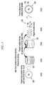
- FIG. 1 is a schematic flowchart of the method for manufacturing the fluorine-based resin coating powder according to an exemplary embodiment of the present disclosure.
- the method for manufacturing the fluorine-based resin coating powder may include a silver powder preparing step (S10) of preparing a silver (Ag) powder 100 having a predetermined grain size, a silver powder solution mixing step (S20) of adding the silver powder 100 to an ethanol solution 110, followed by mixing, a PH adjustment solution preparing step (S30) of preparing a solution 120 having a pH that is adjusted to a set PH, a fluorine silane preparing step (S40) of preparing fluorine silane 130, and a fluorine-based resin coating silver powder manufacturing step (S50) of manufacturing a fluorine-based resin coating silver powder 200 coated with the fluorine-based resin 140 at a set thickness by adding the silver powder mixed with the ethanol solution 110 in the silver powder solution mixing step (S20) and fluorine silane 130 prepared in the fluorine silane preparing step (S40) to the solution 120 having the pH that is adjusted to the PH
- the grain size of the silver powder 100 may be 10 nm to 10 ⁇ m, and a set coating thickness of the fluorine-based resin 140 may be 1 nm to 10 nm.
- the surface may not be coated well due to an agglomeration phenomenon of the silver powder 100, which is not suitable.
- the size of the silver powder 100 is 10 ⁇ m or more, the size may be larger than about 1000 times of an actual coating thickness, and thus a friction reduction effect by coating may not be large, which is not suitable.
- a temperature at which the contact point is sintered may be largely increased to 600°C or more, so that there may be concern about damage to a coating film, which is not suitable.
- the grain size of the silver powder 100 is 20 nm to 10 ⁇ m, and it may be suitable that the coating thickness of the fluorine-based resin 140 is 1 nm to 10 nm.
- the pH of the solution 120 may be set to the range of 2 to 7.5 (the optimum range is 4 to 6).
- the reason why the range of the pH is set as described above is that when the pH is 2 or less, it may be difficult to attain a desired effect by the content of the solvent, and when the pH is 7.5 or more, since the solution has alkalinity, a reaction speed may be very slow, and thus it may be difficult to manufacture the fluorine-based resin coating powder.
- the pH of the solution 120 may be adjusted to the set PH by using the acid.
- the acid may be formed of an acidic solution not leaving a salt component in drying, such as a nitric acid and an acetic acid.
- the fluorine silane may be formed of any one selected from perfluorooctyl triethoxysilane, triethyl(trifluoromethyl)silane, trimethyl(trifluoromethyl)silane, trimethoxy (3,3,3-trifluoropropyl)silane, trimethyl(trifluoromethyl)silane, dimethoxy-methyl (3,3,3-trifluoropropyl)silane, diisopropyl (3,3,4,4,5,5,6,6-nonafluorohexyl)silane, triethoxy[4-(trifluoromethyl)phenyl]silane, 1H,1H,2H,2H-perfluorooctyltriethoxysilane, and the like.
- FIG. 2 is a schematic flowchart of the method for manufacturing the electrode material according to an exemplary embodiment of the present disclosure.
- the description of the method for manufacturing the electrode material according to an exemplary embodiment of the present disclosure is the same as that of the method for manufacturing the fluorine-based resin coating powder according to an exemplary embodiment of the present disclosure with the exception of the following particular description, and thus the full detailed description thereof will be omitted.
- the method for manufacturing the electrode material may include a fluorine-based resin coating silver powder preparing step (S100) of preparing a fluorine-based resin coating silver powder 200 where a silver (Ag) powder 100 having a predetermined grain size is coated with a fluorine-based resin 140 at a set thickness, a silver powder preparing step (S110) of preparing the silver (Ag) powder 100 having the predetermined grain size, a silver powder mixing step (S120) of mixing the fluorine-based resin coating silver powder 200 prepared in the fluorine-based resin coating silver powder preparing step (S110) and the silver powder 100 prepared in the silver powder preparing step, and a sintering step (S130) of printing a mixture powder 210 mixed in the silver powder mixing step (S130) on a surface of an electrode (contact point base material) 300 and then sintering the mixture powder at a set sintering temperature.
- S100 fluorine-based resin coating silver powder preparing step
- S110 of preparing the silver (Ag
- the grain size of the silver powder 100 may be 10 nm to 10 ⁇ m, and a set coating thickness of the fluorine-based resin 140 may be 1 nm to 10 nm.
- the surface may not be coated well due to an agglomeration phenomenon of the silver powder 100, which may not be suitable.
- the size of the silver powder 100 is 10 ⁇ m or more, the size may be larger than about 1000 times of an actual coating thickness, and thus a friction reduction effect by coating may not be large, which may not be suitable.
- a temperature at which the contact point is sintered may be largely increased to 600°C or more, so that there may be concern about damage to a coating film, which may not be suitable.
- the grain size of the silver powder 100 is 20 nm to 10 ⁇ m, and it may be suitable that the coating thickness of the fluorine-based resin 140 is 1 nm to 10 nm.
- the sintering temperature may be in the range of about 300 to 350°C.
- a sintering time may be in the range of 1 to 30 minutes according to a printing amount.
- a sintering thickness on the surface of the electrode may be 0.5 to 100 ⁇ m.
- the sintering step (S130) since the silver powder has the nano-size, sintering may be feasible at the printing temperature of about 300°C which is lower than an actual melting point. At this temperature, since the fluorine-based resin 140 is not damaged, a desired result in the present disclosure may be obtained.
- the electrode (contact point base material) 300 may be formed of copper (Cu) and the like.
- the silver (Ag) powder 100 having the grain size of 10 nm to 10 ⁇ m is prepared, the silver powder 100 is added to the ethanol solution 110, followed by mixing (S20), the solution 120 having the pH that is adjusted to 5.5 by using HNO 3 is prepared (S30), and fluorine silane 130 is prepared (S40).
- the fluorine-based resin coating silver powder 200 coated with the fluorine-based resin 140 at a set thickness is manufactured by adding the silver powder 100 mixed with the ethanol solution 110 in the silver powder solution mixing step (S20) and the fluorine silane 130 prepared in the fluorine silane preparing step (S40) to the solution 120 having the pH that is adjusted to the PH set in the PH adjustment solution preparing step (S30), followed by mixing.
- the coating thickness of the fluorine-based resin 140 may be set to 1 nm to 10 nm.
- the silver powder 200 which is coated with the fluorine-based resin, and the silver powder 100, which is not coated with the fluorine-based resin, are appropriately mixed, and the mixture powder 210 is then printed on the surface of the electrode (contact point base material) 300 (S130).
- the mixture powder 210 printed on the surface of the electrode (contact point base material) 300 may be sintered at about 300 to 350°C for 1 to 30 minutes according to a printing amount.
- the silver powder 100 has a nano-size, sintering is feasible at the printing temperature of about 300°C which is lower than an actual melting point. At this temperature, since the fluorine-based resin is not damaged, a desired result in the present disclosure may be obtained.
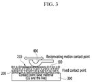
- FIG. 3 is a view illustrating a use state of the electrode material manufactured according to a method for manufacturing the fluorine-based resin coating powder and an electrode material according to an exemplary embodiment of the present disclosure.
- abrasion may occur on the surface of the contact point base material 300 as the switch 400 is operated, and in this case, the fluorine silane 130 of the surface of the fluorine-based resin coating silver powder 200 trespasses on the sintered pore to attain the continuous lubrication effect, and this phenomenon may reduce the friction coefficient of the contact point and improve abrasion resistance characteristics.
- [Table 1] is a table exhibiting comparison evaluation results of the existing technology (silver plating) and the Example of the present disclosure (fluorine-based resin coating silver powder) with respect to the abrasion resistance lifespan (number) according to the kind of the contact point.
Landscapes
- Chemical & Material Sciences (AREA)
- Engineering & Computer Science (AREA)
- Organic Chemistry (AREA)
- Materials Engineering (AREA)
- Spectroscopy & Molecular Physics (AREA)
- Physics & Mathematics (AREA)
- Wood Science & Technology (AREA)
- Life Sciences & Earth Sciences (AREA)
- Chemical Kinetics & Catalysis (AREA)
- Composite Materials (AREA)
- Manufacturing & Machinery (AREA)
- Polymers & Plastics (AREA)
- Medicinal Chemistry (AREA)
- Health & Medical Sciences (AREA)
- Mechanical Engineering (AREA)
- General Chemical & Material Sciences (AREA)
- Oil, Petroleum & Natural Gas (AREA)
- Powder Metallurgy (AREA)
- Other Surface Treatments For Metallic Materials (AREA)
- Manufacture Of Switches (AREA)
Abstract
Description
- This application claims the benefit of priority to Korean Patent Application No.
10-2015-0148693, filed with the Korean Intellectual Property Office on October 26, 2015 - The present disclosure relates to a method for manufacturing a fluorine-based resin coating powder and an electrode material, and more particularly, to a method for manufacturing a fluorine-based resin coating powder and an electrode material which is capable of improving durability and reliability of a switch contact point.
- Currently, about 100 or more switch contact points may be used in a vehicle. This is a phenomenon due to an increase in the number of electronic devices in the vehicle. These switches are essential parts of vehicle operation, and durability and reliability of the switches is directly connected to quality and reliability of the vehicle.
- For example, if a consumer feels like opening a window of a driver's seat of the vehicle and thus operates a power window switch, but the window is not opened due to a failure in the switch, the consumer does not consider the event as a failure in the switch, but seems to consider that an entire vehicle window system is faulty.
- Further, switches is used as important parts in controlling the vehicle. For example, a brake switch serves to transfer signals regarding whether a driver steps on a brake to various controllers, and to operate a brake lamp of a rear combination lamp of a rear part. Therefore, if the brake switch is out of order, a problem occurs in various control systems, and the brake lamp of the rear part is not turned on.
- As described above, in accordance with an increase in importance of the switches in the vehicle, an importance of a contact point material that is essential to a lifespan and reliability of the switch has risen.
- In a technology for improving workability by reducing an insertion force of a connector as an example of an existing technology, in order to reduce a surface friction coefficient, a coating film including a mixture of a fluorine-based resin particulate and fluorine-based oil can be formed on a surface of a contact point material base material of the connector.
- Herein, a thickness of the coating film can be 0.2 to 0.5 µm, and a ratio of the fluorine-based resin particulate is 20 mass% to 40 mass% based on the total content of the fluorine-based resin particulate and fluorine-based oil in the coating film.
- Like the connector, in the case where contact pressure is high and there is no movement once the connector is engaged, in engagement the friction coefficient is small, insertion force is low, and contact resistance is not largely increased.
- However, in this technology, since a coating layer is thinly distributed on only the surface of the contact point material base material of the connector, coating peeling according to sliding durability occurs, and even though the coating thickness is 0.2 µm, this technology is disadvantageous in terms of contact resistance.
- Further, in a case where grease is applied in order to reduce the friction coefficient of the switch contact point as another example of the existing technology, the following problems may exist. In general, when the switch is designed, it is assumed that the switch is operated on a flat surface. However, the switch/connector may be equipped in a slanted form. There is a problem in that if the grease is exposed at a high temperature over a long period of time, a viscosity of the grease is reduced, and the grease flows down toward a lower side of a slanted surface, and thus an intended function of the grease is lost.
- The above information disclosed in this Background section is only for enhancement of understanding of the background of the disclosure and therefore it may contain information that does not form the prior art that is already known in this country to a person of ordinary skill in the art.
- The present disclosure has been made in an effort to provide a method for manufacturing a fluorine-based resin coating powder and an electrode material, which may improve durability and reliability of a switch contact point and reduce a conductivity performance of a switch and a friction coefficient of the switch contact point itself to reduce abrasion.
- An exemplary embodiment of the present disclosure provides a method for manufacturing a fluorine-based resin coating powder, the method may include: a silver powder preparing step of preparing a silver powder having a predetermined grain size,
a silver powder solution mixing step of adding the silver powder to an ethanol solution, followed by mixing,
a PH adjustment solution preparing step of preparing a solution having a pH that is adjusted to a set PH,
a fluorine silane preparing step of preparing fluorine silane, and
a fluorine-based resin coating silver powder manufacturing step of manufacturing a fluorine-based resin coating silver powder coated with the fluorine-based resin at a set thickness by adding the silver powder mixed with the ethanol solution in the silver powder solution mixing step and the fluorine silane prepared in the fluorine silane preparing step to the solution having the pH that is adjusted to the PH set in the PH adjustment solution preparing step, followed by mixing. - In the silver powder preparing step, the grain size may be 10 nm to 10 µm.
- A coating thickness of the fluorine-based resin may be 1 nm to 10 nm.
- In the PH adjustment solution preparing step, the pH of the solution may be set to a range of 2 to 7.5.
- In the PH adjustment solution preparing step, the pH of the solution may be adjusted to the set pH by using an acid.
- The acid may be formed of a nitric acid and an acetic acid not leaving a salt component in drying.
- The fluorine silane may be formed of any one selected from perfluorooctyl triethoxysilane, triethyl(trifluoromethyl)silane, trimethyl(trifluoromethyl)silane, trimethoxy (3,3,3-trifluoropropyl)silane, trimethyl(trifluoromethyl)silane, dimethoxy-methyl (3,3,3-trifluoropropyl)silane, diisopropyl (3,3,4,4,5,5,6,6-nonafluorohexyl)silane, triethoxy[4-(trifluoromethyl)phenyl]silane, and 1H,1H,2H,2H-perfluorooctyltriethoxysilane.
- Another exemplary embodiment of the present disclosure provides a method for manufacturing an electrode material, the method may include: a fluorine-based resin coating silver powder preparing step of preparing a fluorine-based resin coating silver powder where a silver powder having a predetermined grain size is coated with a fluorine-based resin at a set thickness,
a silver powder preparing step of preparing the silver powder having the predetermined grain size,
a silver powder mixing step of mixing the fluorine-based resin coating silver powder prepared in the fluorine-based resin coating silver powder preparing step and the silver powder prepared in the silver powder preparing step, and
a sintering step of printing a mixture powder mixed in the silver powder mixing step on a surface of an electrode and then sintering the mixture powder at a set sintering temperature. - In the silver powder preparing step, the grain size may be 10 nm to 10 µm.
- A coating thickness of the fluorine-based resin may be 1 nm to 10 nm.
- In the sintering step, the sintering temperature may be set to a range of 300 to 350°C.
- In the sintering step, a sintering time may be set to a range of 1 to 30 minutes according to a printing amount.
- According to the exemplary embodiments of the present disclosure, it is possible to simultaneously secure abrasion resistance and electric conductivity of an electric contact point.
- As compared to general silver (Ag) plating, a friction coefficient is reduced and abrasion is reduced, and as compared to existing resin coating, electric conductivity is excellent (this is because resin coating is a non-conductive film and disturbs conductivity).
- Further, fluorine silane of a surface of a fluorine-based resin coating silver powder trespasses on a sintered pore (pore effect) to attain a continuous lubrication effect, and thus even after performing repeated times, it is possible to attain the continuous lubrication effect.
- In addition, even though a switch and a connector are equipped in a slanted form, a lubrication component does not flow down, and it is possible to reduce a silver plate thickness as compared to the same durable lifespan.
-
-
FIG. 1 is a schematic flowchart of a method for manufacturing a fluorine-based resin coating powder according to an exemplary embodiment of the present disclosure. -
FIG. 2 is a schematic flowchart of a method for manufacturing an electrode material according to an exemplary embodiment of the present disclosure. -
FIG. 3 is a view illustrating a use state of the electrode material manufactured according to the method for manufacturing the fluorine-based resin coating powder and the electrode material according to an exemplary embodiment of the present disclosure. - The present disclosure will be described more fully hereinafter with reference to the accompanying drawings, in which exemplary embodiments of the disclosure are shown so as to be easily understood by the person with ordinary skill in the art. As easily understood by the person with ordinary skill in the art to which the present disclosure pertains, the exemplary embodiments which will be described below may be variously modified without departing from the spirit and the scope of the present disclosure. If possible, the same or similar portions are represented by using the same reference numeral in the drawings.
- The terminologies used hereinafter are set forth just to illustrate a specific exemplary embodiment but not to limit the present disclosure. It must be noted that, as used in the specification and the appended claims, the singular forms include plural references unless the context clearly dictates otherwise. It will be further understood that the terms "comprises", when used in this specification, specify the presence of stated properties, regions, integers, steps, operations, elements, and/or components, but do not preclude the presence or addition of one or more other properties, regions, integers, steps, operations, elements, components, and/or groups.
- All terms including technical terms and scientific terms used herein have the same meaning as the meaning generally understood by the person with ordinary skill in the art to which the present disclosure pertains. The terminologies that are defined previously are further understood to have the meaning that coincides with relating technical documents and the contents that are disclosed currently, but not interpreted as the ideal or very official meaning unless it is defined.
- A method for manufacturing a fluorine-based resin coating powder and an electrode material according to an exemplary embodiment of the present disclosure is a contact point material technology, or method, of reducing friction coefficients of a connector and a switch to reduce abrasion of a sliding-type contact point and thus improve electric durability and reliability, and allows metals sufficiently to come into contact with each other so that the friction coefficient is reduced but an electric conductive performance is not largely affected.
-
FIG. 1 is a schematic flowchart of the method for manufacturing the fluorine-based resin coating powder according to an exemplary embodiment of the present disclosure. - Referring to
FIG. 1 , the method for manufacturing the fluorine-based resin coating powder according to the exemplary embodiment of the present disclosure may include a silver powder preparing step (S10) of preparing a silver (Ag)powder 100 having a predetermined grain size, a silver powder solution mixing step (S20) of adding thesilver powder 100 to anethanol solution 110, followed by mixing, a PH adjustment solution preparing step (S30) of preparing asolution 120 having a pH that is adjusted to a set PH, a fluorine silane preparing step (S40) of preparingfluorine silane 130, and a fluorine-based resin coating silver powder manufacturing step (S50) of manufacturing a fluorine-based resincoating silver powder 200 coated with the fluorine-basedresin 140 at a set thickness by adding the silver powder mixed with theethanol solution 110 in the silver powder solution mixing step (S20) andfluorine silane 130 prepared in the fluorine silane preparing step (S40) to thesolution 120 having the pH that is adjusted to the PH set in the PH adjustment solution preparing step (S30), followed by mixing. - In the silver powder preparing step S10, the grain size of the
silver powder 100 may be 10 nm to 10 µm, and a set coating thickness of the fluorine-basedresin 140 may be 1 nm to 10 nm. - In a case where the grain size of the
silver powder 100 is 10 nm or less, the surface may not be coated well due to an agglomeration phenomenon of thesilver powder 100, which is not suitable. - In addition, in a case where the grain size of the
silver powder 100 is 10 µm or more, the size may be larger than about 1000 times of an actual coating thickness, and thus a friction reduction effect by coating may not be large, which is not suitable. - Further, in a case where the grain size of the
silver powder 100 is 10 µm or more, a temperature at which the contact point is sintered may be largely increased to 600°C or more, so that there may be concern about damage to a coating film, which is not suitable. - Therefore, it may be suitable that the grain size of the
silver powder 100 is 20 nm to 10 µm, and it may be suitable that the coating thickness of the fluorine-basedresin 140 is 1 nm to 10 nm. - In the PH adjustment solution preparing step S30, the pH of the
solution 120 may be set to the range of 2 to 7.5 (the optimum range is 4 to 6). The reason why the range of the pH is set as described above is that when the pH is 2 or less, it may be difficult to attain a desired effect by the content of the solvent, and when the pH is 7.5 or more, since the solution has alkalinity, a reaction speed may be very slow, and thus it may be difficult to manufacture the fluorine-based resin coating powder. - In the PH adjustment solution preparing step S30, the pH of the
solution 120 may be adjusted to the set PH by using the acid. - The acid may be formed of an acidic solution not leaving a salt component in drying, such as a nitric acid and an acetic acid.
- The fluorine silane may be formed of any one selected from perfluorooctyl triethoxysilane, triethyl(trifluoromethyl)silane, trimethyl(trifluoromethyl)silane, trimethoxy (3,3,3-trifluoropropyl)silane, trimethyl(trifluoromethyl)silane, dimethoxy-methyl (3,3,3-trifluoropropyl)silane, diisopropyl (3,3,4,4,5,5,6,6-nonafluorohexyl)silane, triethoxy[4-(trifluoromethyl)phenyl]silane, 1H,1H,2H,2H-perfluorooctyltriethoxysilane, and the like.
-
FIG. 2 is a schematic flowchart of the method for manufacturing the electrode material according to an exemplary embodiment of the present disclosure. - The description of the method for manufacturing the electrode material according to an exemplary embodiment of the present disclosure is the same as that of the method for manufacturing the fluorine-based resin coating powder according to an exemplary embodiment of the present disclosure with the exception of the following particular description, and thus the full detailed description thereof will be omitted.
- Referring to
FIG. 2 , the method for manufacturing the electrode material according to an exemplary embodiment of the present disclosure may include a fluorine-based resin coating silver powder preparing step (S100) of preparing a fluorine-based resincoating silver powder 200 where a silver (Ag)powder 100 having a predetermined grain size is coated with a fluorine-basedresin 140 at a set thickness, a silver powder preparing step (S110) of preparing the silver (Ag)powder 100 having the predetermined grain size, a silver powder mixing step (S120) of mixing the fluorine-based resincoating silver powder 200 prepared in the fluorine-based resin coating silver powder preparing step (S110) and thesilver powder 100 prepared in the silver powder preparing step, and a sintering step (S130) of printing amixture powder 210 mixed in the silver powder mixing step (S130) on a surface of an electrode (contact point base material) 300 and then sintering the mixture powder at a set sintering temperature. - In the silver powder preparing step (S110), the grain size of the
silver powder 100 may be 10 nm to 10 µm, and a set coating thickness of the fluorine-basedresin 140 may be 1 nm to 10 nm. - In a case where the grain size of the
silver powder 100 is 10 nm or less, the surface may not be coated well due to an agglomeration phenomenon of thesilver powder 100, which may not be suitable. - In addition, in a case where the grain size of the
silver powder 100 is 10 µm or more, the size may be larger than about 1000 times of an actual coating thickness, and thus a friction reduction effect by coating may not be large, which may not be suitable. - Further, in the case where the grain size of the
silver powder 100 is 10 µm or more, a temperature at which the contact point is sintered may be largely increased to 600°C or more, so that there may be concern about damage to a coating film, which may not be suitable. - Therefore, it may be suitable that the grain size of the
silver powder 100 is 20 nm to 10 µm, and it may be suitable that the coating thickness of the fluorine-basedresin 140 is 1 nm to 10 nm. - In the sintering step (S130), the sintering temperature may be in the range of about 300 to 350°C.
- In the sintering step (S130), a sintering time may be in the range of 1 to 30 minutes according to a printing amount.
- In the sintering step (S130), a sintering thickness on the surface of the electrode may be 0.5 to 100 µm.
- In the sintering step (S130), since the silver powder has the nano-size, sintering may be feasible at the printing temperature of about 300°C which is lower than an actual melting point. At this temperature, since the fluorine-based
resin 140 is not damaged, a desired result in the present disclosure may be obtained. - The electrode (contact point base material) 300 may be formed of copper (Cu) and the like.
- Hereinafter, an action of the method for manufacturing the fluorine-based resin coating powder and the electrode material according to the exemplary embodiment of the present disclosure will be described with reference to
FIGS. 1 and2 . - After the
silver powder 100 is manufactured in a fine size, through fluorine-based resin coating treatment, a novel type fluorine-based resincoating silver powder 200 is manufactured. - That is, the silver (Ag)
powder 100 having the grain size of 10 nm to 10 µm is prepared, thesilver powder 100 is added to theethanol solution 110, followed by mixing (S20), thesolution 120 having the pH that is adjusted to 5.5 by using HNO3 is prepared (S30), andfluorine silane 130 is prepared (S40). - In addition, the fluorine-based resin
coating silver powder 200 coated with the fluorine-basedresin 140 at a set thickness is manufactured by adding thesilver powder 100 mixed with theethanol solution 110 in the silver powder solution mixing step (S20) and thefluorine silane 130 prepared in the fluorine silane preparing step (S40) to thesolution 120 having the pH that is adjusted to the PH set in the PH adjustment solution preparing step (S30), followed by mixing. - In this case, the coating thickness of the fluorine-based
resin 140 may be set to 1 nm to 10 nm. - In addition, as described above, after the fluorine-based resin
coating silver powder 200 coated with the fluorine-basedresin 140 at the set thickness is manufactured, thesilver powder 200, which is coated with the fluorine-based resin, and thesilver powder 100, which is not coated with the fluorine-based resin, are appropriately mixed, and themixture powder 210 is then printed on the surface of the electrode (contact point base material) 300 (S130). - In addition, after printing, the
mixture powder 210 printed on the surface of the electrode (contact point base material) 300 may be sintered at about 300 to 350°C for 1 to 30 minutes according to a printing amount. - Since the
silver powder 100 has a nano-size, sintering is feasible at the printing temperature of about 300°C which is lower than an actual melting point. At this temperature, since the fluorine-based resin is not damaged, a desired result in the present disclosure may be obtained. -
FIG. 3 is a view illustrating a use state of the electrode material manufactured according to a method for manufacturing the fluorine-based resin coating powder and an electrode material according to an exemplary embodiment of the present disclosure. - Referring to
FIG. 3 , abrasion may occur on the surface of the contactpoint base material 300 as theswitch 400 is operated, and in this case, thefluorine silane 130 of the surface of the fluorine-based resincoating silver powder 200 trespasses on the sintered pore to attain the continuous lubrication effect, and this phenomenon may reduce the friction coefficient of the contact point and improve abrasion resistance characteristics. - [Table 1] is a table exhibiting comparison evaluation results of the existing technology (silver plating) and the Example of the present disclosure (fluorine-based resin coating silver powder) with respect to the abrasion resistance lifespan (number) according to the kind of the contact point.
- According to the following [Table 1], it can be seen that in the case of the Example of the present disclosure (fluorine-based resin coating silver powder), as compared to the case of the existing technology (silver plating), the abrasion resistance lifespan (number) is significantly increased.
[Table 1] Classification Existing Technology (silver plating) Example of the Present Disclosure (fluorine-based resin coating silver powder 1 µm 5 µm 20 µm 5 µm 10 µm 1 55,670 301,054 1,910,154 2,510,245 6,541,215 2 60,247 312,574 2,117,557 2,915,515 6,687,144 3 54,328 354,245 2,520,136 2,717,389 6,781,102 4 57,234 294,387 2,312,228 2,880,108 6,241,047 5 59,214 332,157 2,215,412 2,651,138 5,987,513 - While this disclosure has been described in connection with what is presently considered to be practical exemplary embodiments, it is to be understood that the disclosure is not limited to the disclosed embodiments, but, on the contrary, is intended to cover various modifications and equivalent arrangements included within the spirit and scope of the appended claims.
Claims (12)
- A method for manufacturing a fluorine-based resin coating powder, the method comprising:a silver powder preparing step of preparing a silver powder having a predetermined grain size;a silver powder solution mixing step of adding the silver powder to an ethanol solution, followed by mixing;a PH adjustment solution preparing step of preparing a solution having a pH that is adjusted to a set PH;a fluorine silane preparing step of preparing fluorine silane; anda fluorine-based resin coating silver powder manufacturing step of manufacturing a fluorine-based resin coating silver powder coated with the fluorine-based resin at a set thickness by adding the silver powder mixed with the ethanol solution in the silver powder solution mixing step and the fluorine silane prepared in the fluorine silane preparing step to the solution having the pH that is adjusted to the PH set in the PH adjustment solution preparing step, followed by mixing.
- The method of claim 1, wherein in the silver powder preparing step, the grain size of the silver powder is 10 nm to 10 µm.
- The method of claim 2, wherein a coating thickness of the fluorine-based resin is 1 nm to 10 nm.
- The method of claim 1, wherein in the PH adjustment solution preparing step, the pH of the solution is set to a range of 2 to 7.5.
- The method of claim 4, wherein in the PH adjustment solution preparing step, the pH of the solution is adjusted to the set pH by using an acid.
- The method of claim 5, wherein the acid is formed of a nitric acid and an acetic acid not leaving a salt component in drying.
- The method of claim 4, wherein the fluorine silane is formed of any one selected from perfluorooctyl triethoxysilane, triethyl(trifluoromethyl)silane, trimethyl(trifluoromethyl)silane, trimethoxy (3,3,3-trifluoropropyl)silane, trimethyl(trifluoromethyl)silane, dimethoxy-methyl (3,3,3-trifluoropropyl)silane, diisopropyl (3,3,4,4,5,5,6,6-nonafluorohexyl)silane, triethoxy[4-(trifluoromethyl)phenyl]silane, and 1H,1H,2H,2H-perfluorooctyltriethoxysilane.
- A method for manufacturing an electrode material, the method comprising:a fluorine-based resin coating silver powder preparing step of preparing a fluorine-based resin coating silver powder where a silver powder having a predetermined grain size is coated with a fluorine-based resin at a set thickness;a silver powder preparing step of preparing the silver powder having the predetermined grain size;a silver powder mixing step of mixing the fluorine-based resin coating silver powder prepared in the fluorine-based resin coating silver powder preparing step and the silver powder prepared in the silver powder preparing step; anda sintering step of printing a mixture powder mixed in the silver powder mixing step on a surface of an electrode and then sintering the mixture powder at a set sintering temperature.
- The method of claim 8, wherein in the silver powder preparing step, the grain size is 10 nm to 10 µm.
- The method of claim 9, wherein a coating thickness of the fluorine-based resin is 1 nm to 10 nm.
- The method of claim 8, wherein in the sintering step, the sintering temperature is set to a range of 300 to 350° C.
- The method of claim 11, wherein in the sintering step, a sintering time is set to a range of 1 to 30 minutes according to a printing amount.
Applications Claiming Priority (1)
| Application Number | Priority Date | Filing Date | Title |
|---|---|---|---|
| KR1020150148693A KR20170047948A (en) | 2015-10-26 | 2015-10-26 | Method for manufacturing coatinn powder of fluororesin, and electrode material |
Publications (2)
| Publication Number | Publication Date |
|---|---|
| EP3162861A1 true EP3162861A1 (en) | 2017-05-03 |
| EP3162861B1 EP3162861B1 (en) | 2018-06-13 |
Family
ID=55854551
Family Applications (1)
| Application Number | Title | Priority Date | Filing Date |
|---|---|---|---|
| EP16155156.9A Active EP3162861B1 (en) | 2015-10-26 | 2016-02-11 | Method for manufacturing fluorine-based resin coating powder and electrode material |
Country Status (5)
| Country | Link |
|---|---|
| US (1) | US20170114227A1 (en) |
| EP (1) | EP3162861B1 (en) |
| JP (1) | JP2017082320A (en) |
| KR (1) | KR20170047948A (en) |
| CN (1) | CN106607583A (en) |
Families Citing this family (1)
| Publication number | Priority date | Publication date | Assignee | Title |
|---|---|---|---|---|
| CN113871056B (en) * | 2021-11-09 | 2024-11-01 | 浙江光达电子科技有限公司 | Silver paste for electrode on the front side of crystalline silicon solar cells |
Citations (3)
| Publication number | Priority date | Publication date | Assignee | Title |
|---|---|---|---|---|
| US20080260957A1 (en) * | 2006-10-27 | 2008-10-23 | Kunihiro Yamada | Method for adhering a thermally-conductive silicone composition, a primer for adhering a thermally-conductive silicone composition and a method for manufacturing a bonded complex of a thermally-conductive silicone composition |
| US20100032308A1 (en) * | 2008-08-05 | 2010-02-11 | Xerox Corporation | Metallization process for making fuser members |
| DE102013214075A1 (en) * | 2013-07-18 | 2015-01-22 | Fraunhofer-Gesellschaft zur Förderung der angewandten Forschung e.V. | Fabric with polymer layer |
Family Cites Families (2)
| Publication number | Priority date | Publication date | Assignee | Title |
|---|---|---|---|---|
| US5008172A (en) * | 1988-05-26 | 1991-04-16 | Ricoh Company, Ltd. | Electrophotographic photoconductor |
| US6841094B2 (en) * | 2002-09-19 | 2005-01-11 | Industrial Technology Research Institute | Fine conductive particles for making anisotropic conductive adhesive composition |
-
2015
- 2015-10-26 KR KR1020150148693A patent/KR20170047948A/en not_active Ceased
-
2016
- 2016-02-10 US US15/040,825 patent/US20170114227A1/en not_active Abandoned
- 2016-02-11 EP EP16155156.9A patent/EP3162861B1/en active Active
- 2016-03-25 CN CN201610178266.4A patent/CN106607583A/en active Pending
- 2016-06-17 JP JP2016120895A patent/JP2017082320A/en active Pending
Patent Citations (3)
| Publication number | Priority date | Publication date | Assignee | Title |
|---|---|---|---|---|
| US20080260957A1 (en) * | 2006-10-27 | 2008-10-23 | Kunihiro Yamada | Method for adhering a thermally-conductive silicone composition, a primer for adhering a thermally-conductive silicone composition and a method for manufacturing a bonded complex of a thermally-conductive silicone composition |
| US20100032308A1 (en) * | 2008-08-05 | 2010-02-11 | Xerox Corporation | Metallization process for making fuser members |
| DE102013214075A1 (en) * | 2013-07-18 | 2015-01-22 | Fraunhofer-Gesellschaft zur Förderung der angewandten Forschung e.V. | Fabric with polymer layer |
Also Published As
| Publication number | Publication date |
|---|---|
| KR20170047948A (en) | 2017-05-08 |
| CN106607583A (en) | 2017-05-03 |
| US20170114227A1 (en) | 2017-04-27 |
| EP3162861B1 (en) | 2018-06-13 |
| JP2017082320A (en) | 2017-05-18 |
Similar Documents
| Publication | Publication Date | Title |
|---|---|---|
| JP6339474B2 (en) | Inductance element and electronic device | |
| EP2911160B1 (en) | Electroconductive paste | |
| KR101301634B1 (en) | Silver-copper composite powder having silver microparticule attached thereto, and method of production of the silver-copper composite powder | |
| CN107256773A (en) | Electronic unit, the manufacture method of electronic unit and electronic equipment | |
| WO2019018613A1 (en) | Dry method of metallizing polymer thick film surfaces | |
| JP2007123832A (en) | Terminal structure of chip-like electrical components | |
| EP3162861B1 (en) | Method for manufacturing fluorine-based resin coating powder and electrode material | |
| EP1819018B1 (en) | Electric contact part, coaxial connector, and electric circuit device using the part and the connector | |
| KR101356377B1 (en) | Nickel powder, method for producing same, and polymer ptc device using such nickel powder | |
| JPH06295616A (en) | Conductive paste for forming film capable of applying soldering | |
| KR20220052886A (en) | Coil electronic component | |
| CN102308352A (en) | Sliding contact assembly | |
| KR101690696B1 (en) | Conductive Particle, Conductive Powder, Conductive Polymer Composition, and Anisotropic Conductive Sheet | |
| JP2016195048A (en) | Silver-coated conductive particles and conductive material containing the same | |
| KR20200037779A (en) | Composite particles, powder, resin composition and molded body | |
| JP4900674B2 (en) | Anisotropic conductive film and method for manufacturing electronic device using the same | |
| KR102951572B1 (en) | Metal-coated resin particles and a method for manufacturing the same, a conductive paste containing metal-coated resin particles, and a conductive film | |
| CN102725801A (en) | Resin electrode paste, and electronic component equipped with resin electrode produced using same | |
| CN104425054B (en) | Conductive paste and the base material with conducting film | |
| JP2009205842A (en) | Conductive fine particle, anisotropic conductive material, and connection structure | |
| JP7540459B2 (en) | Polymer-type conductive paste, conductive film, and solid electrolytic capacitor element | |
| JP2006202550A (en) | Conductive paste, wiring board using the same, electronic component mounting board, and electronic equipment using the same | |
| KR101219005B1 (en) | Thin metal film electrode and fabricating method thereod | |
| CN114521046B (en) | Circuit board and manufacturing method thereof | |
| JP4014547B2 (en) | Wiring body forming material, wiring body, and manufacturing method of wiring body |
Legal Events
| Date | Code | Title | Description |
|---|---|---|---|
| PUAI | Public reference made under article 153(3) epc to a published international application that has entered the european phase |
Free format text: ORIGINAL CODE: 0009012 |
|
| STAA | Information on the status of an ep patent application or granted ep patent |
Free format text: STATUS: THE APPLICATION HAS BEEN PUBLISHED |
|
| AK | Designated contracting states |
Kind code of ref document: A1 Designated state(s): AL AT BE BG CH CY CZ DE DK EE ES FI FR GB GR HR HU IE IS IT LI LT LU LV MC MK MT NL NO PL PT RO RS SE SI SK SM TR |
|
| AX | Request for extension of the european patent |
Extension state: BA ME |
|
| STAA | Information on the status of an ep patent application or granted ep patent |
Free format text: STATUS: REQUEST FOR EXAMINATION WAS MADE |
|
| STAA | Information on the status of an ep patent application or granted ep patent |
Free format text: STATUS: EXAMINATION IS IN PROGRESS |
|
| 17P | Request for examination filed |
Effective date: 20170727 |
|
| RBV | Designated contracting states (corrected) |
Designated state(s): AL AT BE BG CH CY CZ DE DK EE ES FI FR GB GR HR HU IE IS IT LI LT LU LV MC MK MT NL NO PL PT RO RS SE SI SK SM TR |
|
| 17Q | First examination report despatched |
Effective date: 20170821 |
|
| GRAP | Despatch of communication of intention to grant a patent |
Free format text: ORIGINAL CODE: EPIDOSNIGR1 |
|
| STAA | Information on the status of an ep patent application or granted ep patent |
Free format text: STATUS: GRANT OF PATENT IS INTENDED |
|
| INTG | Intention to grant announced |
Effective date: 20180124 |
|
| GRAS | Grant fee paid |
Free format text: ORIGINAL CODE: EPIDOSNIGR3 |
|
| GRAA | (expected) grant |
Free format text: ORIGINAL CODE: 0009210 |
|
| STAA | Information on the status of an ep patent application or granted ep patent |
Free format text: STATUS: THE PATENT HAS BEEN GRANTED |
|
| AK | Designated contracting states |
Kind code of ref document: B1 Designated state(s): AL AT BE BG CH CY CZ DE DK EE ES FI FR GB GR HR HU IE IS IT LI LT LU LV MC MK MT NL NO PL PT RO RS SE SI SK SM TR |
|
| REG | Reference to a national code |
Ref country code: GB Ref legal event code: FG4D |
|
| REG | Reference to a national code |
Ref country code: CH Ref legal event code: EP Ref country code: AT Ref legal event code: REF Ref document number: 1008482 Country of ref document: AT Kind code of ref document: T Effective date: 20180615 |
|
| REG | Reference to a national code |
Ref country code: IE Ref legal event code: FG4D |
|
| REG | Reference to a national code |
Ref country code: DE Ref legal event code: R096 Ref document number: 602016003417 Country of ref document: DE |
|
| REG | Reference to a national code |
Ref country code: NL Ref legal event code: MP Effective date: 20180613 |
|
| REG | Reference to a national code |
Ref country code: LT Ref legal event code: MG4D |
|
| PG25 | Lapsed in a contracting state [announced via postgrant information from national office to epo] |
Ref country code: SE Free format text: LAPSE BECAUSE OF FAILURE TO SUBMIT A TRANSLATION OF THE DESCRIPTION OR TO PAY THE FEE WITHIN THE PRESCRIBED TIME-LIMIT Effective date: 20180613 Ref country code: LT Free format text: LAPSE BECAUSE OF FAILURE TO SUBMIT A TRANSLATION OF THE DESCRIPTION OR TO PAY THE FEE WITHIN THE PRESCRIBED TIME-LIMIT Effective date: 20180613 Ref country code: FI Free format text: LAPSE BECAUSE OF FAILURE TO SUBMIT A TRANSLATION OF THE DESCRIPTION OR TO PAY THE FEE WITHIN THE PRESCRIBED TIME-LIMIT Effective date: 20180613 Ref country code: NO Free format text: LAPSE BECAUSE OF FAILURE TO SUBMIT A TRANSLATION OF THE DESCRIPTION OR TO PAY THE FEE WITHIN THE PRESCRIBED TIME-LIMIT Effective date: 20180913 Ref country code: CY Free format text: LAPSE BECAUSE OF FAILURE TO SUBMIT A TRANSLATION OF THE DESCRIPTION OR TO PAY THE FEE WITHIN THE PRESCRIBED TIME-LIMIT Effective date: 20180613 Ref country code: BG Free format text: LAPSE BECAUSE OF FAILURE TO SUBMIT A TRANSLATION OF THE DESCRIPTION OR TO PAY THE FEE WITHIN THE PRESCRIBED TIME-LIMIT Effective date: 20180913 |
|
| PG25 | Lapsed in a contracting state [announced via postgrant information from national office to epo] |
Ref country code: RS Free format text: LAPSE BECAUSE OF FAILURE TO SUBMIT A TRANSLATION OF THE DESCRIPTION OR TO PAY THE FEE WITHIN THE PRESCRIBED TIME-LIMIT Effective date: 20180613 Ref country code: LV Free format text: LAPSE BECAUSE OF FAILURE TO SUBMIT A TRANSLATION OF THE DESCRIPTION OR TO PAY THE FEE WITHIN THE PRESCRIBED TIME-LIMIT Effective date: 20180613 Ref country code: GR Free format text: LAPSE BECAUSE OF FAILURE TO SUBMIT A TRANSLATION OF THE DESCRIPTION OR TO PAY THE FEE WITHIN THE PRESCRIBED TIME-LIMIT Effective date: 20180914 Ref country code: HR Free format text: LAPSE BECAUSE OF FAILURE TO SUBMIT A TRANSLATION OF THE DESCRIPTION OR TO PAY THE FEE WITHIN THE PRESCRIBED TIME-LIMIT Effective date: 20180613 |
|
| REG | Reference to a national code |
Ref country code: AT Ref legal event code: MK05 Ref document number: 1008482 Country of ref document: AT Kind code of ref document: T Effective date: 20180613 |
|
| PG25 | Lapsed in a contracting state [announced via postgrant information from national office to epo] |
Ref country code: NL Free format text: LAPSE BECAUSE OF FAILURE TO SUBMIT A TRANSLATION OF THE DESCRIPTION OR TO PAY THE FEE WITHIN THE PRESCRIBED TIME-LIMIT Effective date: 20180613 |
|
| PG25 | Lapsed in a contracting state [announced via postgrant information from national office to epo] |
Ref country code: SK Free format text: LAPSE BECAUSE OF FAILURE TO SUBMIT A TRANSLATION OF THE DESCRIPTION OR TO PAY THE FEE WITHIN THE PRESCRIBED TIME-LIMIT Effective date: 20180613 Ref country code: EE Free format text: LAPSE BECAUSE OF FAILURE TO SUBMIT A TRANSLATION OF THE DESCRIPTION OR TO PAY THE FEE WITHIN THE PRESCRIBED TIME-LIMIT Effective date: 20180613 Ref country code: AT Free format text: LAPSE BECAUSE OF FAILURE TO SUBMIT A TRANSLATION OF THE DESCRIPTION OR TO PAY THE FEE WITHIN THE PRESCRIBED TIME-LIMIT Effective date: 20180613 Ref country code: PL Free format text: LAPSE BECAUSE OF FAILURE TO SUBMIT A TRANSLATION OF THE DESCRIPTION OR TO PAY THE FEE WITHIN THE PRESCRIBED TIME-LIMIT Effective date: 20180613 Ref country code: IS Free format text: LAPSE BECAUSE OF FAILURE TO SUBMIT A TRANSLATION OF THE DESCRIPTION OR TO PAY THE FEE WITHIN THE PRESCRIBED TIME-LIMIT Effective date: 20181013 Ref country code: CZ Free format text: LAPSE BECAUSE OF FAILURE TO SUBMIT A TRANSLATION OF THE DESCRIPTION OR TO PAY THE FEE WITHIN THE PRESCRIBED TIME-LIMIT Effective date: 20180613 Ref country code: RO Free format text: LAPSE BECAUSE OF FAILURE TO SUBMIT A TRANSLATION OF THE DESCRIPTION OR TO PAY THE FEE WITHIN THE PRESCRIBED TIME-LIMIT Effective date: 20180613 |
|
| PG25 | Lapsed in a contracting state [announced via postgrant information from national office to epo] |
Ref country code: ES Free format text: LAPSE BECAUSE OF FAILURE TO SUBMIT A TRANSLATION OF THE DESCRIPTION OR TO PAY THE FEE WITHIN THE PRESCRIBED TIME-LIMIT Effective date: 20180613 Ref country code: IT Free format text: LAPSE BECAUSE OF FAILURE TO SUBMIT A TRANSLATION OF THE DESCRIPTION OR TO PAY THE FEE WITHIN THE PRESCRIBED TIME-LIMIT Effective date: 20180613 Ref country code: SM Free format text: LAPSE BECAUSE OF FAILURE TO SUBMIT A TRANSLATION OF THE DESCRIPTION OR TO PAY THE FEE WITHIN THE PRESCRIBED TIME-LIMIT Effective date: 20180613 |
|
| REG | Reference to a national code |
Ref country code: DE Ref legal event code: R097 Ref document number: 602016003417 Country of ref document: DE |
|
| PLBE | No opposition filed within time limit |
Free format text: ORIGINAL CODE: 0009261 |
|
| STAA | Information on the status of an ep patent application or granted ep patent |
Free format text: STATUS: NO OPPOSITION FILED WITHIN TIME LIMIT |
|
| 26N | No opposition filed |
Effective date: 20190314 |
|
| PG25 | Lapsed in a contracting state [announced via postgrant information from national office to epo] |
Ref country code: DK Free format text: LAPSE BECAUSE OF FAILURE TO SUBMIT A TRANSLATION OF THE DESCRIPTION OR TO PAY THE FEE WITHIN THE PRESCRIBED TIME-LIMIT Effective date: 20180613 Ref country code: SI Free format text: LAPSE BECAUSE OF FAILURE TO SUBMIT A TRANSLATION OF THE DESCRIPTION OR TO PAY THE FEE WITHIN THE PRESCRIBED TIME-LIMIT Effective date: 20180613 |
|
| REG | Reference to a national code |
Ref country code: CH Ref legal event code: PL |
|
| PG25 | Lapsed in a contracting state [announced via postgrant information from national office to epo] |
Ref country code: MC Free format text: LAPSE BECAUSE OF FAILURE TO SUBMIT A TRANSLATION OF THE DESCRIPTION OR TO PAY THE FEE WITHIN THE PRESCRIBED TIME-LIMIT Effective date: 20180613 Ref country code: LU Free format text: LAPSE BECAUSE OF NON-PAYMENT OF DUE FEES Effective date: 20190211 |
|
| REG | Reference to a national code |
Ref country code: BE Ref legal event code: MM Effective date: 20190228 |
|
| REG | Reference to a national code |
Ref country code: IE Ref legal event code: MM4A |
|
| PG25 | Lapsed in a contracting state [announced via postgrant information from national office to epo] |
Ref country code: AL Free format text: LAPSE BECAUSE OF FAILURE TO SUBMIT A TRANSLATION OF THE DESCRIPTION OR TO PAY THE FEE WITHIN THE PRESCRIBED TIME-LIMIT Effective date: 20180613 |
|
| PG25 | Lapsed in a contracting state [announced via postgrant information from national office to epo] |
Ref country code: CH Free format text: LAPSE BECAUSE OF NON-PAYMENT OF DUE FEES Effective date: 20190228 Ref country code: LI Free format text: LAPSE BECAUSE OF NON-PAYMENT OF DUE FEES Effective date: 20190228 |
|
| PG25 | Lapsed in a contracting state [announced via postgrant information from national office to epo] |
Ref country code: IE Free format text: LAPSE BECAUSE OF NON-PAYMENT OF DUE FEES Effective date: 20190211 |
|
| PG25 | Lapsed in a contracting state [announced via postgrant information from national office to epo] |
Ref country code: BE Free format text: LAPSE BECAUSE OF NON-PAYMENT OF DUE FEES Effective date: 20190228 |
|
| PG25 | Lapsed in a contracting state [announced via postgrant information from national office to epo] |
Ref country code: TR Free format text: LAPSE BECAUSE OF FAILURE TO SUBMIT A TRANSLATION OF THE DESCRIPTION OR TO PAY THE FEE WITHIN THE PRESCRIBED TIME-LIMIT Effective date: 20180613 |
|
| PG25 | Lapsed in a contracting state [announced via postgrant information from national office to epo] |
Ref country code: MT Free format text: LAPSE BECAUSE OF NON-PAYMENT OF DUE FEES Effective date: 20190211 Ref country code: PT Free format text: LAPSE BECAUSE OF FAILURE TO SUBMIT A TRANSLATION OF THE DESCRIPTION OR TO PAY THE FEE WITHIN THE PRESCRIBED TIME-LIMIT Effective date: 20181015 |
|
| GBPC | Gb: european patent ceased through non-payment of renewal fee |
Effective date: 20200211 |
|
| PG25 | Lapsed in a contracting state [announced via postgrant information from national office to epo] |
Ref country code: GB Free format text: LAPSE BECAUSE OF NON-PAYMENT OF DUE FEES Effective date: 20200211 |
|
| PG25 | Lapsed in a contracting state [announced via postgrant information from national office to epo] |
Ref country code: HU Free format text: LAPSE BECAUSE OF FAILURE TO SUBMIT A TRANSLATION OF THE DESCRIPTION OR TO PAY THE FEE WITHIN THE PRESCRIBED TIME-LIMIT; INVALID AB INITIO Effective date: 20160211 |
|
| PG25 | Lapsed in a contracting state [announced via postgrant information from national office to epo] |
Ref country code: MK Free format text: LAPSE BECAUSE OF FAILURE TO SUBMIT A TRANSLATION OF THE DESCRIPTION OR TO PAY THE FEE WITHIN THE PRESCRIBED TIME-LIMIT Effective date: 20180613 |
|
| P01 | Opt-out of the competence of the unified patent court (upc) registered |
Effective date: 20230526 |
|
| PGFP | Annual fee paid to national office [announced via postgrant information from national office to epo] |
Ref country code: DE Payment date: 20260120 Year of fee payment: 11 |
|
| PGFP | Annual fee paid to national office [announced via postgrant information from national office to epo] |
Ref country code: FR Payment date: 20260121 Year of fee payment: 11 |