EP3162291A1 - Ultrasonic probe - Google Patents
Ultrasonic probe Download PDFInfo
- Publication number
- EP3162291A1 EP3162291A1 EP16183093.0A EP16183093A EP3162291A1 EP 3162291 A1 EP3162291 A1 EP 3162291A1 EP 16183093 A EP16183093 A EP 16183093A EP 3162291 A1 EP3162291 A1 EP 3162291A1
- Authority
- EP
- European Patent Office
- Prior art keywords
- unit
- supporting
- shaft
- supporting member
- ultrasonic probe
- Prior art date
- Legal status (The legal status is an assumption and is not a legal conclusion. Google has not performed a legal analysis and makes no representation as to the accuracy of the status listed.)
- Granted
Links
- XDTMQSROBMDMFD-UHFFFAOYSA-N C1CCCCC1 Chemical compound C1CCCCC1 XDTMQSROBMDMFD-UHFFFAOYSA-N 0.000 description 1
Images








Classifications
-
- A—HUMAN NECESSITIES
- A61—MEDICAL OR VETERINARY SCIENCE; HYGIENE
- A61B—DIAGNOSIS; SURGERY; IDENTIFICATION
- A61B8/00—Diagnosis using ultrasonic, sonic or infrasonic waves
-
- A—HUMAN NECESSITIES
- A61—MEDICAL OR VETERINARY SCIENCE; HYGIENE
- A61B—DIAGNOSIS; SURGERY; IDENTIFICATION
- A61B8/00—Diagnosis using ultrasonic, sonic or infrasonic waves
- A61B8/44—Constructional features of the ultrasonic, sonic or infrasonic diagnostic device
- A61B8/4444—Constructional features of the ultrasonic, sonic or infrasonic diagnostic device related to the probe
-
- A—HUMAN NECESSITIES
- A61—MEDICAL OR VETERINARY SCIENCE; HYGIENE
- A61B—DIAGNOSIS; SURGERY; IDENTIFICATION
- A61B8/00—Diagnosis using ultrasonic, sonic or infrasonic waves
- A61B8/44—Constructional features of the ultrasonic, sonic or infrasonic diagnostic device
-
- A—HUMAN NECESSITIES
- A61—MEDICAL OR VETERINARY SCIENCE; HYGIENE
- A61B—DIAGNOSIS; SURGERY; IDENTIFICATION
- A61B8/00—Diagnosis using ultrasonic, sonic or infrasonic waves
- A61B8/44—Constructional features of the ultrasonic, sonic or infrasonic diagnostic device
- A61B8/4405—Device being mounted on a trolley
-
- A—HUMAN NECESSITIES
- A61—MEDICAL OR VETERINARY SCIENCE; HYGIENE
- A61B—DIAGNOSIS; SURGERY; IDENTIFICATION
- A61B8/00—Diagnosis using ultrasonic, sonic or infrasonic waves
- A61B8/44—Constructional features of the ultrasonic, sonic or infrasonic diagnostic device
- A61B8/4444—Constructional features of the ultrasonic, sonic or infrasonic diagnostic device related to the probe
- A61B8/4461—Features of the scanning mechanism, e.g. for moving the transducer within the housing of the probe
-
- A—HUMAN NECESSITIES
- A61—MEDICAL OR VETERINARY SCIENCE; HYGIENE
- A61B—DIAGNOSIS; SURGERY; IDENTIFICATION
- A61B8/00—Diagnosis using ultrasonic, sonic or infrasonic waves
- A61B8/44—Constructional features of the ultrasonic, sonic or infrasonic diagnostic device
- A61B8/4483—Constructional features of the ultrasonic, sonic or infrasonic diagnostic device characterised by features of the ultrasound transducer
-
- A—HUMAN NECESSITIES
- A61—MEDICAL OR VETERINARY SCIENCE; HYGIENE
- A61B—DIAGNOSIS; SURGERY; IDENTIFICATION
- A61B2562/00—Details of sensors; Constructional details of sensor housings or probes; Accessories for sensors
- A61B2562/18—Shielding or protection of sensors from environmental influences, e.g. protection from mechanical damage
- A61B2562/187—Strain relief means
Definitions
- Embodiments of the present disclosure relate to an ultrasonic probe to obtain ultrasonic images.
- An ultrasonic imaging apparatus is an apparatus configured to radiate ultrasonic signals toward a target portion at an inside of a body from a surface of the body of a subject, and obtain images related to a cross section of a soft tissue or a blood flow by use of the information of the reflected ultrasonic signals, that is, ultrasonic echo signals, through a non-invasive method.
- the ultrasonic imaging apparatus when compared to other image diagnosis apparatuses such as an x-ray diagnostic apparatus, an x-ray Computerized Tomography Scanner , a Magnetic Resonance Image (MRI), and a nuclear medicine diagnosis apparatus, is provided in a small size and less costly, while capable of displaying in real time basis, and is provided with high stability while less exposed to radiation, and thus is widely used in diagnosis of hearts, abdomens, urinary systems, and in gynecology.
- image diagnosis apparatuses such as an x-ray diagnostic apparatus, an x-ray Computerized Tomography Scanner , a Magnetic Resonance Image (MRI), and a nuclear medicine diagnosis apparatus.
- an ultrasonic probe includes a transducer rotatably provided; a shaft at which the transducer is mounted; and a supporting member rotatably supporting the shaft, and the supporting member is provided with a buffer unit to mitigate an outside impact.
- the buffer unit may be provided by forming a hole at one side of the supporting member.
- the buffer unit may be provided by bending the supporting member such that a portion of the supporting member forms a curved surface.
- the buffer unit may be provided using material having elasticity and mounted at the supporting member.
- the supporting member may be provided using material having elasticity.
- the buffer unit may be provided to be deformed by an outside impact and returned to an original state when the outside force is removed.
- the supporting member may include a first supporting unit at which the shaft is mounted, and a second supporting unit fixed to a base frame.
- the buffer unit may be provided in the shape of a hole that is formed at the second supporting unit.
- the first supporting unit may be connected to the second supporting unit by a connection unit.
- the buffer unit may be an elastic member mounted at the connection unit and elastically supporting the first supporting unit and the second supporting unit.
- connection unit and the elastic member each may be provided in plural.
- the first supporting unit, the second supporting unit, and the connection unit may be integrally formed with one another.
- the first supporting unit may be provided with an insertion hole into which the shaft is inserted.
- the buffer unit may be provided between an inner side surface of the first supporting unit forming the insertion hole and the shaft.
- the buffer unit may include an elastic member provided in the shape of a ring.
- an ultrasonic probe includes a transducer, a shaft, a supporting member, and a base frame.
- the transducer may be configured to transmit/receive ultrasonic waves.
- the shaft may have the transducer mounted thereat and configured to rotate by a driving force received from a driving source.
- the supporting member may be configured to rotatably support the shaft.
- the base frame may have the supporting member fixed thereto.
- the supporting member may be provided with a buffer unit having an elasticity as to prevent deformation of the shaft or the supporting member by mitigating an impact applied to the shaft or the supporting member.
- the buffer unit may be provided by forming a hole at one side of the supporting member.
- the buffer unit may be provided by mounting an elastic member at one side of the supporting member.
- the buffer unit may be provided by bending the supporting member to form a curved surface.
- the supporting member may be provided with an insertion hole into which the shaft is rotatably inserted.
- the buffer unit may be positioned in between an inner side surface of the supporting member forming the insertion hole and an outer side surface of the shaft.
- FIG. 1 is a drawing illustrating an ultrasonic imaging apparatus according to one embodiment of the present disclosure.
- an ultrasonic imaging apparatus 1 includes a body 10, and a probe 20 to transmit ultrasonic signals at a subject to be diagnosed and to receive the reflected ultrasonic signals from the subject.
- the probe 20 may be connected to the body 10 by use of a cable.
- the body 10 may be provided with a display 30 to display diagnostic results obtained from the received ultrasonic signals.
- the display 30 may be provided with applications related to the motions of the ultrasonic imaging apparatus 1 displayed thereto.
- the display 30 may be provided with the information related to the ultrasonic images obtained in the process of an ultrasonic diagnosis or the motions of the ultrasonic imaging apparatus 1 displayed thereto.
- the display 30 may be implemented in the form of a Cathode Ray Tube (CRT) or a Liquid Crystal Display (LCD).
- the display 30 may be provided in a plurality of units.
- the display 30 may include a main display and a sub display.
- the main display may be provided with ultrasonic images obtained in an ultrasonic diagnostic process displayed thereto
- the sub display may be provided with the information related to the motions of the ultrasonic imaging apparatus displayed thereto.
- the body 10 may be provided with in input unit 40.
- the input unit 40 may be provided in the form of a keyboard, a foot switch, or a foot pedal. In a case when the input unit 40 is provided in the form of the keyboard, the keyboard may be provided at an upper portion of the body 10. In a case when the input unit 40 is provided in the form of the foot switch or the foot pedal, the foot switch or the foot pedal may be provided at a lower portion of the body 10. An administrator may control the motions of the ultrasonic imaging apparatus 1 through the input unit 40.
- the body 10 may be provided with a moving apparatus 12 as to move the ultrasonic imaging apparatus 1.
- the moving apparatus 12 may be a plurality of casters provided at a lower surface of the body 10. The casters may be aligned as to drive the body 10 in a predetermined direction, or locked as to stop the body 10 at a predetermined position.
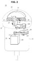
- FIG. 2 is a drawing illustrating a probe according to one embodiment of the present disclosure.
- a probe 20 includes a transducer 21 rotatably provided.
- the probe 20 may be provided with a handle case 23 provided as to use the transducer 21 as a user grasps the handle case 23.
- a front end of the handle case 23 may be provided with a cap 24 disposed thereto as the cap 24 is adjacent to a subject to be diagnosed.
- the transducer 21 may be provided at an inside of the cap 24.
- the transducer 21 may include an ultrasonic oscillator to transmit and receive ultrasonic waves.
- the transducer 21 may be rotatably installed at an inside of the cap 24, and may read three-dimensional images of the subject to be diagnosed.
- the transducer 21 may be mounted at a shaft 27.
- the shaft 27 may be rotated while transferred with a driving force from a driving apparatus 22. As the shaft 27 is rotated, the transducer 21 mounted at the shaft 27 may be rotated together.
- the cap 24 may be provided with an inner surface corresponding to an outer surface of the transducer 22 such that the gap between the inner surface of the cap 24 and the outer surface of the transducer 21 may be steadily maintained even in a case when the transducer 21 installed at an inside of the cap 24 is rotated.
- the outer surface of the transducer 21 and the inner surface of the cap 24 each may be provided in the shape of a ring having an identical central portion.
- An inside space of the cap 24 may be filled with oil configured to perform a role as a medium to have the ultrasonic waves generated at the transducer 21 transferred.
- a base frame 25 may be provided in between the cap 24 and the handle case 23 as to divide an inside space of the cap 24 and an inside space of the handle case 23.
- the oil may be filled in a space 200 formed by use of the cap 24 and the base frame 25.
- the shaft 27 may be rotated while transferred with a driving force from the driving apparatus 22.
- the driving apparatus 22 may be accommodated at an inside of the handle case 23.
- the driving apparatus 22 may include a driving motor 220, pulleys 221, 223, and 224 configured to be transferred with a driving force from the driving motor 220, and wires 222 and 225 to transfer the driving force of the driving motor 220.
- a first pulley 221 may be rotated while transferred with the driving force of the driving motor 220.
- a first wire 222 may connect the first pulley 221 and a second pulley 223. The driving force transferred to the first pulley 221 by use of the first wire 222 may be transferred to the second pulley 223.
- the second pulley 223 and a third pulley 224 may be connected by use of a transfer unit 226.
- the transfer unit 226 may be a shaft connecting the second pulley 223 and the third pulley 224.
- the second pulley 223 and the third pulley 224 may be fixed to one end portion and the other end portion of the shaft, respectively.
- the third pulley 224 may be rotated along with the second pulley 223 as the second pulley 223 is rotated while transferred with a driving force.
- the type of the transfer unit 226 is not limited to a shaft.
- the transfer unit 226 may be adequately structured according to an inside structure of an inside of the handle case 23.
- the transfer unit 226 may be provided with a structure having the pulleys and the wires, or may be provided with a structure by use of a gear connection.
- the second pulley 223 and the third pulley 224 are connected by use of the shaft will be described.
- the third pulley 224 may be rotated along with the second pulley 223.
- the shaft 27 may be provided with a driving force transferring member 28 mounted thereto.
- the driving force transferring member 28 may be rotated along with the shaft 27 while fixed to one side of the shaft 27.
- the driving force transferring member 28 and the third pulley 224 may be connected by use of a second wire 225.
- the driving force transferring member 28 may be rotated as the rotational force is transferred by use of the second wire 225.
- the shaft 27 may be rotated along with the driving force transferring member 28.
- the second wire 225 may be wound at the third pulley 224, and may be provided to wrap around a portion of an outer circumferential surface of the driving force transferring member 28.
- One end portion of the second wire 225 may be connected to a first elastic member 291, and the other end portion of the second wire 225 may be connected to a second elastic member 292.
- the tension of the second wire 225 may be maintained. Therefore, a loosening of the second wire 225 from the rotation of the driving force transferring member 28 may be prevented.
- the shaft 27 may be rotatably mounted at a supporting member 26.
- the supporting member 26 may be protruded from the base frame 25.
- the shaft 27 may be rotated in one direction or the other direction while transferred with a driving force from the driving apparatus 22 as the shaft 27 is mounted at the supporting member 26.
- the supporting member 26 may include a first supporting member 26a provided at one end portion side of the shaft 27, and a second supporting member 26b provided at the other end portion side of the shaft 27.
- FIG. 3 is a drawing illustrating a probe according to another embodiment of the present disclosure.
- the driving force of a driving force 22' of a probe 20' may be transferred to the shaft 27 by use of a gear connection.
- a driving motor 220' may be provided with a rotating gear 227 configured to rotate by use of the driving force of the driving motor 220'.
- An outer circumferential surface of a driving force transferring member 28' may be provided with a gear unit 280 teeth-coupled to the rotating gear 227.
- the driving force transferring member 28' may be rotated in a counter-clockwise direction.
- the driving force transferring member 28' may be rotated in a clockwise direction.
- the shaft 27 may be rotated in a clockwise direction or a counter-clockwise direction along with the driving force transferring member 28'.
- the structure other than the driving apparatus 22' may be applied similarly to the structure of the probe 20 illustrated on FIG. 2 .
- the structure of the supporting member 26 of the probe 20 disclosed on FIG. 2 will be described.
- the probe 20' disclosed on FIG. 3 may be provided with the hereinafter descriptions similarly applied hereto.
- FIG. 4 is a drawing illustrating a supporting member according to one embodiment of the present disclosure.
- the supporting member 26 may include a first supporting unit 261 mounted at the base frame 25, and a second supporting unit 262 at which the shaft 27 is mounted.
- the first supporting unit 261 and the second supporting unit 262 may be integrally formed with one another.
- the supporting member 26 may be provided with metallic material having the hardness to support the shaft 27, and configured to be flexibly responsive with respect to an outside impact.
- the supporting member 26 may be provided with metallic material, including aluminum.
- the second supporting member 262 may be provided with an insertion hole 260 into which the shaft is inserted formed thereto.
- the shaft 27 may be insertedly fixed to the insertion hole 260.
- the diameter D2 of the insertion hole 260 may be identical to or somewhat larger than the diameter D1 of the shaft 27.
- the first supporting member 261 may be provided with a buffer unit 263 configured to ease the impact applied to the supporting member 26. While using the probe 20, even when an impact is applied to the cap 24 as the probe 20 is dropped by a user, the impact is eased by use of the buffer unit 263, and the inside components of the probe 20 being damaged by the displacement of the shaft 27 may be prevented.
- the buffer unit 263 may be provided in the shape of a hole formed at the first supporting unit 261.
- the hole may be formed lengthways in a width direction W of the first supporting unit 261.
- the buffer unit 263 is formed in the shape of a hole formed lengthways in the width direction W of the first supporting unit 261, but the shape or the number of the hole is not limited hereto, and may be formed in various shapes and numbers.
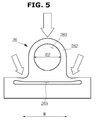
- FIG. 5 is a drawing illustrating an image when an impact is applied to the supporting member according to one embodiment of the present disclosure
- FIG. 6 and FIG. 7 are drawings illustrating images before and after an impact is applied to the probe according to one embodiment of the present disclosure.
- the impact applied to the supporting member 26 and the shaft 27 may be eased by use of the buffer unit 263.
- the central axis of rotation of the transducer 21 may be prevented from being changed or the components provided at an inside of the cap 24 may be prevented from being damaged.
- the buffer 263 when an impact is applied to the cap 24, a collision of the cap 24 and the transducer 21 may be occurred.
- the shaft 27 at which the transducer 21 is mounted may be pressed by the impact of the cap 24 and the transducer 21.
- the supporting member 26 may be pressed toward a side of the base frame 25 by the shaft 27, and a deformation may be occurred by the force applied.
- the central axis of rotation of the shaft 27 at which the transducer 21 is mounted may be changed.
- the central axis of rotation of the transducer 21 may also be changed.
- the ultrasonic images obtained by use of the transducer 21 may be different from the ultrasonic images obtained by use of the transducer 21 prior to when the impact is applied to the probe 20. Therefore, after an impact is applied to the probe 20, the reliability of the ultrasonic images by use of the transducer 21 may be decreased.
- component damage may be occurred as the contact is made between the inside components as a result of the deformation of the supporting member 26 and the shaft 27.
- the buffer unit 263 is provided at the supporting member 26, even when an outside impact is applied to the probe 20, the impact may be eased by use of the buffer unit 263, so that the reliability of the ultrasonic images may be prevented from being decreased or the inside component may be prevented from being damaged.
- the force applied to the supporting member 26 through the transducer 21 may be transferred after being eased by use of the buffer unit 263.
- the supporting member 26 may be provided with the shape thereof temporarily deformed by the force applied, but by the use of the buffer unit 263, the supporting member 26 may be restored to a state prior to the force being applied. Therefore, the axial deformation of the shaft 27 may not be occurred before and after an impact is applied to the probe 20, and the inside component may be prevented from being damaged by the impact.
- the impact applied to the supporting member 26 may be eased as the shape of the hole provided at the first supporting unit 261 is deformed. As illustrated on FIG. 5 to FIG. 7 , the shape of the hole may be deformed by the outside impact. As the hole is pressed by the impact applied to an upper portion side of the second supporting unit 262, the height H2 of the supporting member 26 when the impact is applied may be further lower when compared to the height H1 of the supporting member 26 before the impact is applied.
- the supporting member 26 When the outside force applied to the supporting member 26 is removed, the supporting member 26 may be restored to a state prior to the impact being applied.
- the shape of the hole may be restored to an original state prior to the impact being applied, and the height of the supporting member 26 may be returned to the height H1 prior to the impact being applied.
- the central axis of rotation of the shaft 27 may be steadily maintained, and the quality of the ultrasonic images by use of the transducer 21 may be steadily maintained.
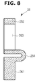
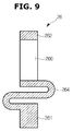
- FIG. 8 to FIG. 10 are side cross-sectional drawings illustrating the embodiments of the supporting members.
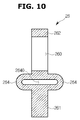
- connection unit 264 may perform a role as a buffer unit configured to ease the impact applied to the supporting member 26 while provided in various shapes.
- connection unit 264 may connect the in between of the first supporting unit 261 and the second supporting unit 262 by means of bypassing as to be provided with a curved surface. That is, the connection unit 264 may be provided to be longer than the shortest distance between the first supporting unit 261 and the second supporting unit 262. That is, the connection unit 264 may be bent to form a curved surface.
- connection unit 264 may be connected to the second supporting unit 262 from the first supporting unit 261 after bypassing in a front direction or a rear direction of the connection unit 264.
- the connection unit 264 may be provided to be bypassing the in between of the first supporting unit 261 and the second supporting unit 262 at least twice in front and rear directions.
- the connection unit 264 by connecting the in between of the first supporting unit 261 and the second supporting unit 262 by bypassing in the front and rear directions may be provided such that an empty space 2640 may be formed at an inside of the connection unit 264.
- the front direction and the rear direction are referred to as the front direction and the rear direction of the supporting member 26 while having a direction directly facing the front of the insertion hole 260, into which the shaft 27 is inserted, as a reference.
- connection unit 264 may be provided with a predetermined elasticity while provided with the length thereof that is longer than the shortest distance between the first supporting unit 261 and the second supporting unit 262 and provided to connect the in between of the first supporting unit 261 and the second supporting unit 262 by bypassing in the front and rear directions. As the above, the connection unit 264 may elastically support the first supporting unit 261 and the second supporting unit 262. The connection unit 264 may perform a role as a buffer unit to mitigate the force applied to the supporting member 26.
- connection unit 264 When an impact is applied to the probe 20 as when the probe 20 is descended by the carelessness of a user and when an impact is occurred in between the cap 24 and the transducer 21, the force applied to the supporting member 26 through the transducer 21 may be buffered by use of the connection unit 264 provided to perform a role as a buffer unit.
- the connection unit 264 may be provided with the shape thereof temporarily deformed by an outside force, but may be restored by use of an elastic force when the outside force is removed. Therefore, the axial deformation of the shaft 27 may not be occurred before and after an impact is applied to the probe 20, and the inside component may be prevented from being damaged by the impact.
- connection unit 264 is provided to have elasticity by use of the shape thereof is not limited to the illustrations provided on FIG. 8 to FIG. 10 .
- the connection unit 264 may be provided to perform a role as a buffer unit to mitigate an outside impact while provided in various shapes.
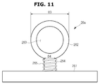
- FIG. 11 and FIG. 12 are drawings illustrating a supporting member according to another embodiment of the present disclosure.
- supporting members 26a and 26b may be provided with connection units 264, 264a and 264b connecting in between of the first supporting unit 261 and the second supporting unit 262.
- the connection unit 264, 264a, and 264b may be provided with elastic members 265, 265a, and 265b as to elastically support the first supporting unit 261 and the second supporting unit 262.
- the diameter of the each of the connection units 264, 264a, and 264b may be provided to be smaller than the diameter D3 of the first supporting member 261.
- the first supporting unit 261 and the second supporting unit 262 of the supporting member 26a may be connected by use of the single connection unit 264.
- the connection unit 264 may be provided with the elastic member 265.
- the elastic member 265 may elastically support the first supporting unit 261 and the second supporting unit 262.
- the force applied to the supporting member 26a through the transducer 21 may be buffered by use of the elastic member 265. That is, the elastic member 265 may perform a role as a buffer unit.
- the supporting member 26a may be provided with the shape thereof temporarily deformed by the force applied, but by the use of the elasticity of the elastic member 265, the supporting member 26a may be restored to a state prior to the force being applied. Therefore, the axial deformation of the shaft 27 may not be occurred before and after an impact is applied to the probe 20, and the inside component may be prevented from being damaged by the impact.
- the first supporting unit 261 and the second supporting unit 262 of the supporting member 26b may be connected by use of the plurality of connection units 264a and 264b.
- the first supporting unit 261 and the second supporting unit 262 are illustrated to be connected by use of the two units of the connection units 264a and 264b while the connection units 264a and 264b are spaced apart with respect to each other, but the number of the connection units is not limited to the illustration provided on FIG. 9 .
- connection units 264a and 264b may be provided with the elastic members 265a and 265b mounted thereto, respectively.
- the connection units 264a and 264b includes a first connection unit5 264a and a second connection unit 264b, the first connection unit 264a may be provided with a first elastic member 265a mounted thereto, and the second connection unit 264b may be provided with a second elastic member 265b mounted thereto.
- the first elastic member 265a and the second elastic member 265b may elastically support the first supporting unit 261 and the second supporting unit 262.
- the impact applied to the supporting member 26 through the transducer 21 may be buffered by use of the elasticity of the first elastic member 265a and the second elastic member 265b. Therefore, the axial deformation of the shaft 27 may not be occurred before and after an impact is applied to the probe 20, and the inside component may be prevented from being damaged by the impact.
- FIG. 13 is a drawing illustrating a supporting member according to still another embodiment of the present disclosure
- FIG. 14 to FIG. 16 are drawings illustrating the embodiments with respect to an inside image of a supporting member according to still another embodiment of the present disclosure.
- the second supporting unit 262 of the supporting member 26 may be provided with a buffer unit 266 along an inner side surface of the second supporting unit 262 forming the insertion hole 260.
- the buffer unit 266 may be provided with material capable of absorbing impact.
- the buffer unit 266 may be provided with the material having elasticity such as elastomer or plastic.
- the insertion hole 260 may be provided with a bearing 267 mounted thereto as to have the rotation of the shaft 27 easily performed.
- the diameter of the bearing 267 may be provided to be identical to the diameter of the shaft 27.
- the shaft 27 may be rotatably provided while inserted into the bearing 267.
- the buffer unit 266 may be provided in between of the bearing 267 and the second supporting unit 262.
- the buffer unit 266 may buffer the impact in between the shaft 27 and the second supporting unit 262.
- the buffer unit 266 may be provided in the shape of a ring having an empty space 2660 formed at an inside of the buffer unit 266.
- the buffer unit 266 may be provided with the material having elasticity such as elastomer or plastic.
- the buffer unit 266 having the shape of a ring provided with the inside space 2660 formed at an inside of the buffer unit 266 is provided to mitigate an outside impact, even when an outside force is applied to the shaft 27, the force applied may be buffered, and thus the axial deformation of the shaft 27 may be prevented and the damage on the inside component by the deformation of the supporting member 26 or the shaft 27 may be prevented.
- the shape of the buffer unit 266 is not limited to the shape of a ring provided with an empty space formed at an inside of the buffer unit 266.
- the buffer unit 266 is provided with an empty space 2662 formed at an inside of the buffer unit 266, and may be provided with a buffer member 269 provided to be positioned at an inside of the inside space 2662 as the buffer member 269 is provided with the material having elasticity.
- the buffer member 269 may be positioned adjacent to an inner wall forming an inside space of the buffer unit 266.
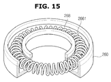
- the buffer unit 266 may be provided in the shape of a ring having an empty space at an inside of the buffer unit 266, or, as illustrated on FIG. 15 and FIG. 16 , the buffer unit 266 may be provided in the shape in which an elastic member 268 or the buffer member 269 is accommodated at an inside space of the buffer unit 266 while one side surface of the buffer unit 266 is provided in an open shape.
- the buffer unit 266 may buffer the outside force applied to the supporting member 26 or the shaft 27 while disclosed in between the shaft 27 and the bearing 267 mounted at a side of the insertion hole 260 as the buffer unit 266 is provided to have elasticity.
- the ultrasonic probe according to one aspect of the present disclosure can mitigate an outside impact while provided with a buffer unit at a supporting member. Accordingly, the components provided at an inside of the ultrasonic probe can be prevented from being damaged. With the above, the quality of ultrasonic images can be prevented from being lowered by an outside impact.
Landscapes
- Health & Medical Sciences (AREA)
- Life Sciences & Earth Sciences (AREA)
- Biomedical Technology (AREA)
- Biophysics (AREA)
- Nuclear Medicine, Radiotherapy & Molecular Imaging (AREA)
- Pathology (AREA)
- Radiology & Medical Imaging (AREA)
- Engineering & Computer Science (AREA)
- Physics & Mathematics (AREA)
- Heart & Thoracic Surgery (AREA)
- Medical Informatics (AREA)
- Molecular Biology (AREA)
- Surgery (AREA)
- Animal Behavior & Ethology (AREA)
- General Health & Medical Sciences (AREA)
- Public Health (AREA)
- Veterinary Medicine (AREA)
- Gynecology & Obstetrics (AREA)
- Ultra Sonic Daignosis Equipment (AREA)
Abstract
Description
- Embodiments of the present disclosure relate to an ultrasonic probe to obtain ultrasonic images.
- An ultrasonic imaging apparatus is an apparatus configured to radiate ultrasonic signals toward a target portion at an inside of a body from a surface of the body of a subject, and obtain images related to a cross section of a soft tissue or a blood flow by use of the information of the reflected ultrasonic signals, that is, ultrasonic echo signals, through a non-invasive method.
- The ultrasonic imaging apparatus, when compared to other image diagnosis apparatuses such as an x-ray diagnostic apparatus, an x-ray Computerized Tomography Scanner , a Magnetic Resonance Image (MRI), and a nuclear medicine diagnosis apparatus, is provided in a small size and less costly, while capable of displaying in real time basis, and is provided with high stability while less exposed to radiation, and thus is widely used in diagnosis of hearts, abdomens, urinary systems, and in gynecology.
- Therefore, it is an aspect of the present disclosure to provide an ultrasonic probe capable of preventing inside components from being damaged by an outside impact.
- Additional aspects of the disclosure will be set forth in part in the description which follows and, in part, will be obvious from the description, or may be learned by practice of the disclosure.
- In accordance with one aspect of the present disclosure, an ultrasonic probe includes a transducer rotatably provided; a shaft at which the transducer is mounted; and a supporting member rotatably supporting the shaft, and the supporting member is provided with a buffer unit to mitigate an outside impact.
- The buffer unit may be provided by forming a hole at one side of the supporting member.
- The buffer unit may be provided by bending the supporting member such that a portion of the supporting member forms a curved surface.
- The buffer unit may be provided using material having elasticity and mounted at the supporting member.
- The supporting member may be provided using material having elasticity.
- The buffer unit may be provided to be deformed by an outside impact and returned to an original state when the outside force is removed.
- The supporting member may include a first supporting unit at which the shaft is mounted, and a second supporting unit fixed to a base frame.
- The buffer unit may be provided in the shape of a hole that is formed at the second supporting unit.
- The first supporting unit may be connected to the second supporting unit by a connection unit.
- The buffer unit may be an elastic member mounted at the connection unit and elastically supporting the first supporting unit and the second supporting unit.
- The connection unit and the elastic member each may be provided in plural.
- The first supporting unit, the second supporting unit, and the connection unit may be integrally formed with one another.
- The first supporting unit may be provided with an insertion hole into which the shaft is inserted.
- The buffer unit may be provided between an inner side surface of the first supporting unit forming the insertion hole and the shaft.
- The buffer unit may include an elastic member provided in the shape of a ring.
- In accordance with another aspect of the present disclosure, an ultrasonic probe includes a transducer, a shaft, a supporting member, and a base frame. The transducer may be configured to transmit/receive ultrasonic waves. The shaft may have the transducer mounted thereat and configured to rotate by a driving force received from a driving source. The supporting member may be configured to rotatably support the shaft. The base frame may have the supporting member fixed thereto. The supporting member may be provided with a buffer unit having an elasticity as to prevent deformation of the shaft or the supporting member by mitigating an impact applied to the shaft or the supporting member.
- The buffer unit may be provided by forming a hole at one side of the supporting member.
- The buffer unit may be provided by mounting an elastic member at one side of the supporting member.
- The buffer unit may be provided by bending the supporting member to form a curved surface.
- The supporting member may be provided with an insertion hole into which the shaft is rotatably inserted.
- The buffer unit may be positioned in between an inner side surface of the supporting member forming the insertion hole and an outer side surface of the shaft.
- These and/or other aspects of the disclosure will become apparent and more readily appreciated from the following description of the embodiments, taken in conjunction with the accompanying drawings of which:
-
FIG. 1 is a drawing illustrating an ultrasonic imaging apparatus according to one embodiment of the present disclosure. -
FIG. 2 is a drawing illustrating a probe according to one embodiment of the present disclosure. -
FIG. 3 is a drawing illustrating a probe according to another embodiment of the present disclosure. -
FIG. 4 is a drawing illustrating a supporting member according to one embodiment of the present disclosure. -
FIG. 5 is a drawing illustrating an image when an impact is applied to the supporting member according to one embodiment of the present disclosure. -
FIG. 6 andFIG. 7 are drawings illustrating images before and after an impact is applied to the probe according to one embodiment of the present disclosure. -
FIG. 8 to FIG. 10 are side -sectional drawings illustrating the embodiments of the supporting members. -
FIG. 11 andFIG. 12 are drawings illustrating a supporting member according to another embodiment of the present disclosure. -
FIG. 13 is a drawing illustrating a supporting member according to still another embodiment of the present disclosure. -
FIG. 14 to FIG. 16 are drawings illustrating the embodiments with respect to an inside image of a supporting member according to still another embodiment of the present disclosure. - Reference will now be made in detail to the embodiments of the present disclosure, examples of which are illustrated in the accompanying drawings, wherein like reference numerals refer to like elements throughout.
-
FIG. 1 is a drawing illustrating an ultrasonic imaging apparatus according to one embodiment of the present disclosure. - Referring to
FIG. 1 , anultrasonic imaging apparatus 1 according to one embodiment of the present disclosure includes abody 10, and aprobe 20 to transmit ultrasonic signals at a subject to be diagnosed and to receive the reflected ultrasonic signals from the subject. Theprobe 20 may be connected to thebody 10 by use of a cable. - The
body 10 may be provided with adisplay 30 to display diagnostic results obtained from the received ultrasonic signals. Thedisplay 30 may be provided with applications related to the motions of theultrasonic imaging apparatus 1 displayed thereto. As one example, thedisplay 30 may be provided with the information related to the ultrasonic images obtained in the process of an ultrasonic diagnosis or the motions of theultrasonic imaging apparatus 1 displayed thereto. - The
display 30 may be implemented in the form of a Cathode Ray Tube (CRT) or a Liquid Crystal Display (LCD). Thedisplay 30 may be provided in a plurality of units. In a case when thedisplay 30 is provided in a plurality of units, thedisplay 30 may include a main display and a sub display. As one example, the main display may be provided with ultrasonic images obtained in an ultrasonic diagnostic process displayed thereto, and the sub display may be provided with the information related to the motions of the ultrasonic imaging apparatus displayed thereto. - The
body 10 may be provided with ininput unit 40. Theinput unit 40 may be provided in the form of a keyboard, a foot switch, or a foot pedal. In a case when theinput unit 40 is provided in the form of the keyboard, the keyboard may be provided at an upper portion of thebody 10. In a case when theinput unit 40 is provided in the form of the foot switch or the foot pedal, the foot switch or the foot pedal may be provided at a lower portion of thebody 10. An administrator may control the motions of theultrasonic imaging apparatus 1 through theinput unit 40. - The
body 10 may be provided with a movingapparatus 12 as to move theultrasonic imaging apparatus 1. The movingapparatus 12 may be a plurality of casters provided at a lower surface of thebody 10. The casters may be aligned as to drive thebody 10 in a predetermined direction, or locked as to stop thebody 10 at a predetermined position. -
FIG. 2 is a drawing illustrating a probe according to one embodiment of the present disclosure. - Referring to
FIG. 2 , aprobe 20 according to one embodiment of the present disclosure includes atransducer 21 rotatably provided. Theprobe 20 may be provided with ahandle case 23 provided as to use thetransducer 21 as a user grasps thehandle case 23. A front end of thehandle case 23 may be provided with acap 24 disposed thereto as thecap 24 is adjacent to a subject to be diagnosed. Thetransducer 21 may be provided at an inside of thecap 24. - The
transducer 21 may include an ultrasonic oscillator to transmit and receive ultrasonic waves. Thetransducer 21 may be rotatably installed at an inside of thecap 24, and may read three-dimensional images of the subject to be diagnosed. - The
transducer 21 may be mounted at ashaft 27. Theshaft 27 may be rotated while transferred with a driving force from a drivingapparatus 22. As theshaft 27 is rotated, thetransducer 21 mounted at theshaft 27 may be rotated together. - The
cap 24 may be provided with an inner surface corresponding to an outer surface of thetransducer 22 such that the gap between the inner surface of thecap 24 and the outer surface of thetransducer 21 may be steadily maintained even in a case when thetransducer 21 installed at an inside of thecap 24 is rotated. As one example, the outer surface of thetransducer 21 and the inner surface of thecap 24 each may be provided in the shape of a ring having an identical central portion. - An inside space of the
cap 24 may be filled with oil configured to perform a role as a medium to have the ultrasonic waves generated at thetransducer 21 transferred. Abase frame 25 may be provided in between thecap 24 and thehandle case 23 as to divide an inside space of thecap 24 and an inside space of thehandle case 23. The oil may be filled in a space 200 formed by use of thecap 24 and thebase frame 25. - The
shaft 27 may be rotated while transferred with a driving force from the drivingapparatus 22. The drivingapparatus 22 may be accommodated at an inside of thehandle case 23. The drivingapparatus 22 may include a drivingmotor 220,pulleys motor 220, andwires motor 220. - A
first pulley 221 may be rotated while transferred with the driving force of the drivingmotor 220. Afirst wire 222 may connect thefirst pulley 221 and asecond pulley 223. The driving force transferred to thefirst pulley 221 by use of thefirst wire 222 may be transferred to thesecond pulley 223. - The
second pulley 223 and athird pulley 224 may be connected by use of atransfer unit 226. As one example, thetransfer unit 226 may be a shaft connecting thesecond pulley 223 and thethird pulley 224. Thesecond pulley 223 and thethird pulley 224 may be fixed to one end portion and the other end portion of the shaft, respectively. As the above, thethird pulley 224 may be rotated along with thesecond pulley 223 as thesecond pulley 223 is rotated while transferred with a driving force. - The type of the
transfer unit 226 is not limited to a shaft. Thetransfer unit 226 may be adequately structured according to an inside structure of an inside of thehandle case 23. Thetransfer unit 226 may be provided with a structure having the pulleys and the wires, or may be provided with a structure by use of a gear connection. - Hereinafter, an embodiment in which the
second pulley 223 and thethird pulley 224 are connected by use of the shaft will be described. As thesecond pulley 223 is rotated while transferred with a driving force, thethird pulley 224 may be rotated along with thesecond pulley 223. - The
shaft 27 may be provided with a drivingforce transferring member 28 mounted thereto. The drivingforce transferring member 28 may be rotated along with theshaft 27 while fixed to one side of theshaft 27. The drivingforce transferring member 28 and thethird pulley 224 may be connected by use of asecond wire 225. As thethird pulley 224 is rotated, the drivingforce transferring member 28 may be rotated as the rotational force is transferred by use of thesecond wire 225. At this time, theshaft 27 may be rotated along with the drivingforce transferring member 28. - The
second wire 225 may be wound at thethird pulley 224, and may be provided to wrap around a portion of an outer circumferential surface of the drivingforce transferring member 28. One end portion of thesecond wire 225 may be connected to a first elastic member 291, and the other end portion of thesecond wire 225 may be connected to a second elastic member 292. As thesecond wire 225 wound at the drivingforce transferring member 28 is connected to the elastic members 291 and 292, even when the drivingforce transferring member 28 is rotated, the tension of thesecond wire 225 may be maintained. Therefore, a loosening of thesecond wire 225 from the rotation of the drivingforce transferring member 28 may be prevented. - The
shaft 27 may be rotatably mounted at a supportingmember 26. The supportingmember 26 may be protruded from thebase frame 25. Theshaft 27 may be rotated in one direction or the other direction while transferred with a driving force from the drivingapparatus 22 as theshaft 27 is mounted at the supportingmember 26. The supportingmember 26 may include a first supportingmember 26a provided at one end portion side of theshaft 27, and a second supportingmember 26b provided at the other end portion side of theshaft 27. -
FIG. 3 is a drawing illustrating a probe according to another embodiment of the present disclosure. - Referring to
FIG. 3 , the driving force of a driving force 22' of a probe 20' according to another embodiment of the present disclosure may be transferred to theshaft 27 by use of a gear connection. A driving motor 220' may be provided with arotating gear 227 configured to rotate by use of the driving force of the driving motor 220'. An outer circumferential surface of a driving force transferring member 28' may be provided with agear unit 280 teeth-coupled to therotating gear 227. - As the
rotating gear 227 is rotated in a clockwise direction by use of the driving motor 220', the driving force transferring member 28' may be rotated in a counter-clockwise direction. As therotating gear 227 is rotated in a counter-clockwise direction by use of the driving motor 220', the driving force transferring member 28' may be rotated in a clockwise direction. Theshaft 27 may be rotated in a clockwise direction or a counter-clockwise direction along with the driving force transferring member 28'. - The structure other than the driving apparatus 22' may be applied similarly to the structure of the
probe 20 illustrated onFIG. 2 . Hereinafter, the structure of the supportingmember 26 of theprobe 20 disclosed onFIG. 2 will be described. The probe 20' disclosed onFIG. 3 may be provided with the hereinafter descriptions similarly applied hereto. -
FIG. 4 is a drawing illustrating a supporting member according to one embodiment of the present disclosure. - Referring to
FIG. 4 , the supportingmember 26 according to one embodiment of the present disclosure may include a first supportingunit 261 mounted at thebase frame 25, and a second supportingunit 262 at which theshaft 27 is mounted. The first supportingunit 261 and the second supportingunit 262 may be integrally formed with one another. - The supporting
member 26 may be provided with metallic material having the hardness to support theshaft 27, and configured to be flexibly responsive with respect to an outside impact. As one example, the supportingmember 26 may be provided with metallic material, including aluminum. - The second supporting
member 262 may be provided with aninsertion hole 260 into which the shaft is inserted formed thereto. Theshaft 27 may be insertedly fixed to theinsertion hole 260. The diameter D2 of theinsertion hole 260 may be identical to or somewhat larger than the diameter D1 of theshaft 27. - The first supporting
member 261 may be provided with abuffer unit 263 configured to ease the impact applied to the supportingmember 26. While using theprobe 20, even when an impact is applied to thecap 24 as theprobe 20 is dropped by a user, the impact is eased by use of thebuffer unit 263, and the inside components of theprobe 20 being damaged by the displacement of theshaft 27 may be prevented. - The
buffer unit 263 may be provided in the shape of a hole formed at the first supportingunit 261. The hole may be formed lengthways in a width direction W of the first supportingunit 261. OnFIG. 4 , thebuffer unit 263 is formed in the shape of a hole formed lengthways in the width direction W of the first supportingunit 261, but the shape or the number of the hole is not limited hereto, and may be formed in various shapes and numbers. -
FIG. 5 is a drawing illustrating an image when an impact is applied to the supporting member according to one embodiment of the present disclosure, andFIG. 6 andFIG. 7 are drawings illustrating images before and after an impact is applied to the probe according to one embodiment of the present disclosure. - Referring to
FIG. 5 to FIG. 7 , when an outside impact is applied to theprobe 20, the impact applied to the supportingmember 26 and theshaft 27 may be eased by use of thebuffer unit 263. As the impact applied to the supportingmember 26 and theshaft 27 is eased by use of thebuffer unit 263, the central axis of rotation of thetransducer 21 may be prevented from being changed or the components provided at an inside of thecap 24 may be prevented from being damaged. - In a case when the
buffer 263 is not provided, when an impact is applied to thecap 24, a collision of thecap 24 and thetransducer 21 may be occurred. Theshaft 27 at which thetransducer 21 is mounted may be pressed by the impact of thecap 24 and thetransducer 21. The supportingmember 26 may be pressed toward a side of thebase frame 25 by theshaft 27, and a deformation may be occurred by the force applied. - As the deformation of the supporting
member 26 is occurred, the central axis of rotation of theshaft 27 at which thetransducer 21 is mounted may be changed. As the central axis of rotation of theshaft 27 is changed, the central axis of rotation of thetransducer 21 may also be changed. As the central axis of rotation of thetransducer 21 is changed, the ultrasonic images obtained by use of thetransducer 21 may be different from the ultrasonic images obtained by use of thetransducer 21 prior to when the impact is applied to theprobe 20. Therefore, after an impact is applied to theprobe 20, the reliability of the ultrasonic images by use of thetransducer 21 may be decreased. In addition, component damage may be occurred as the contact is made between the inside components as a result of the deformation of the supportingmember 26 and theshaft 27. - However, in a case when the
buffer unit 263 is provided at the supportingmember 26, even when an outside impact is applied to theprobe 20, the impact may be eased by use of thebuffer unit 263, so that the reliability of the ultrasonic images may be prevented from being decreased or the inside component may be prevented from being damaged. - When an impact is occurred between the
cap 24 and thetransducer 21 as the impact is applied to theprobe 20, the force applied to the supportingmember 26 through thetransducer 21 may be transferred after being eased by use of thebuffer unit 263. The supportingmember 26 may be provided with the shape thereof temporarily deformed by the force applied, but by the use of thebuffer unit 263, the supportingmember 26 may be restored to a state prior to the force being applied. Therefore, the axial deformation of theshaft 27 may not be occurred before and after an impact is applied to theprobe 20, and the inside component may be prevented from being damaged by the impact. - That is, when an outside impact is applied to the
transducer 21, the impact applied to the supportingmember 26 may be eased as the shape of the hole provided at the first supportingunit 261 is deformed. As illustrated onFIG. 5 to FIG. 7 , the shape of the hole may be deformed by the outside impact. As the hole is pressed by the impact applied to an upper portion side of the second supportingunit 262, the height H2 of the supportingmember 26 when the impact is applied may be further lower when compared to the height H1 of the supportingmember 26 before the impact is applied. - When the outside force applied to the supporting
member 26 is removed, the supportingmember 26 may be restored to a state prior to the impact being applied. The shape of the hole may be restored to an original state prior to the impact being applied, and the height of the supportingmember 26 may be returned to the height H1 prior to the impact being applied. - As the above, as the shape of the hole provided at the first supporting
unit 261 is changed, the impact applied to the supportingmember 26 is eased, and the deformation of the supportingmember 26 may be prevented. Therefore, the central axis of rotation of theshaft 27 may be steadily maintained, and the quality of the ultrasonic images by use of thetransducer 21 may be steadily maintained. -
FIG. 8 to FIG. 10 are side cross-sectional drawings illustrating the embodiments of the supporting members. - Referring to
FIG. 8 to FIG. 10 , the first supportingunit 261 and the second supportingunit 262 of the supportingmember 26 may be connected by use of aconnection unit 264. Theconnection unit 264 may perform a role as a buffer unit configured to ease the impact applied to the supportingmember 26 while provided in various shapes. - Referring to
FIG. 8 to FIG. 10 , theconnection unit 264 may connect the in between of the first supportingunit 261 and the second supportingunit 262 by means of bypassing as to be provided with a curved surface. That is, theconnection unit 264 may be provided to be longer than the shortest distance between the first supportingunit 261 and the second supportingunit 262. That is, theconnection unit 264 may be bent to form a curved surface. - As illustrated on
FIG. 8 , theconnection unit 264 may be connected to the second supportingunit 262 from the first supportingunit 261 after bypassing in a front direction or a rear direction of theconnection unit 264. As illustrated onFIG. 9 , theconnection unit 264 may be provided to be bypassing the in between of the first supportingunit 261 and the second supportingunit 262 at least twice in front and rear directions. In addition, as illustrated onFIG. 10 , theconnection unit 264 by connecting the in between of the first supportingunit 261 and the second supportingunit 262 by bypassing in the front and rear directions, may be provided such that anempty space 2640 may be formed at an inside of theconnection unit 264. - Here, the front direction and the rear direction are referred to as the front direction and the rear direction of the supporting
member 26 while having a direction directly facing the front of theinsertion hole 260, into which theshaft 27 is inserted, as a reference. - The
connection unit 264 may be provided with a predetermined elasticity while provided with the length thereof that is longer than the shortest distance between the first supportingunit 261 and the second supportingunit 262 and provided to connect the in between of the first supportingunit 261 and the second supportingunit 262 by bypassing in the front and rear directions. As the above, theconnection unit 264 may elastically support the first supportingunit 261 and the second supportingunit 262. Theconnection unit 264 may perform a role as a buffer unit to mitigate the force applied to the supportingmember 26. - When an impact is applied to the
probe 20 as when theprobe 20 is descended by the carelessness of a user and when an impact is occurred in between thecap 24 and thetransducer 21, the force applied to the supportingmember 26 through thetransducer 21 may be buffered by use of theconnection unit 264 provided to perform a role as a buffer unit. Theconnection unit 264 may be provided with the shape thereof temporarily deformed by an outside force, but may be restored by use of an elastic force when the outside force is removed. Therefore, the axial deformation of theshaft 27 may not be occurred before and after an impact is applied to theprobe 20, and the inside component may be prevented from being damaged by the impact. - The embodiment in which the
connection unit 264 is provided to have elasticity by use of the shape thereof is not limited to the illustrations provided onFIG. 8 to FIG. 10 . Theconnection unit 264 may be provided to perform a role as a buffer unit to mitigate an outside impact while provided in various shapes. -
FIG. 11 andFIG. 12 are drawings illustrating a supporting member according to another embodiment of the present disclosure. - Referring to
FIG. 11 andFIG. 12 , supportingmembers connection units unit 261 and the second supportingunit 262. Theconnection unit elastic members unit 261 and the second supportingunit 262. The diameter of the each of theconnection units member 261. - As illustrated on
FIG. 11 , the first supportingunit 261 and the second supportingunit 262 of the supportingmember 26a may be connected by use of thesingle connection unit 264. Theconnection unit 264 may be provided with theelastic member 265. Theelastic member 265 may elastically support the first supportingunit 261 and the second supportingunit 262. - When an outside impact is applied to the
probe 20 and when an impact is occurred in between of thecap 24 and thetransducer 21, the force applied to the supportingmember 26a through thetransducer 21 may be buffered by use of theelastic member 265. That is, theelastic member 265 may perform a role as a buffer unit. - The supporting
member 26a may be provided with the shape thereof temporarily deformed by the force applied, but by the use of the elasticity of theelastic member 265, the supportingmember 26a may be restored to a state prior to the force being applied. Therefore, the axial deformation of theshaft 27 may not be occurred before and after an impact is applied to theprobe 20, and the inside component may be prevented from being damaged by the impact. - As illustrated on
FIG. 13 , the first supportingunit 261 and the second supportingunit 262 of the supportingmember 26b may be connected by use of the plurality ofconnection units FIG. 9 , the first supportingunit 261 and the second supportingunit 262 are illustrated to be connected by use of the two units of theconnection units connection units FIG. 9 . - The plurality of
connection units elastic members connection units first connection unit5 264a and asecond connection unit 264b, thefirst connection unit 264a may be provided with a firstelastic member 265a mounted thereto, and thesecond connection unit 264b may be provided with a secondelastic member 265b mounted thereto. The firstelastic member 265a and the secondelastic member 265b may elastically support the first supportingunit 261 and the second supportingunit 262. - As described on
FIG. 11 , in a case when an impact is applied to theprobe 20 as theprobe 20 is dropped by a user, the impact applied to the supportingmember 26 through thetransducer 21 may be buffered by use of the elasticity of the firstelastic member 265a and the secondelastic member 265b. Therefore, the axial deformation of theshaft 27 may not be occurred before and after an impact is applied to theprobe 20, and the inside component may be prevented from being damaged by the impact. -
FIG. 13 is a drawing illustrating a supporting member according to still another embodiment of the present disclosure, andFIG. 14 to FIG. 16 are drawings illustrating the embodiments with respect to an inside image of a supporting member according to still another embodiment of the present disclosure. - Referring to
FIG. 13 to FIG. 16 , the second supportingunit 262 of the supportingmember 26 may be provided with abuffer unit 266 along an inner side surface of the second supportingunit 262 forming theinsertion hole 260. Thebuffer unit 266 may be provided with material capable of absorbing impact. As one example, thebuffer unit 266 may be provided with the material having elasticity such as elastomer or plastic. - The
insertion hole 260 may be provided with abearing 267 mounted thereto as to have the rotation of theshaft 27 easily performed. The diameter of thebearing 267 may be provided to be identical to the diameter of theshaft 27. Theshaft 27 may be rotatably provided while inserted into thebearing 267. - The
buffer unit 266 may be provided in between of thebearing 267 and the second supportingunit 262. Thebuffer unit 266 may buffer the impact in between theshaft 27 and the second supportingunit 262. - As illustrated on
FIG. 14 , thebuffer unit 266 may be provided in the shape of a ring having anempty space 2660 formed at an inside of thebuffer unit 266. At this time, thebuffer unit 266 may be provided with the material having elasticity such as elastomer or plastic. As thebuffer unit 266 having the shape of a ring provided with theinside space 2660 formed at an inside of thebuffer unit 266 is provided to mitigate an outside impact, even when an outside force is applied to theshaft 27, the force applied may be buffered, and thus the axial deformation of theshaft 27 may be prevented and the damage on the inside component by the deformation of the supportingmember 26 or theshaft 27 may be prevented. The shape of thebuffer unit 266 is not limited to the shape of a ring provided with an empty space formed at an inside of thebuffer unit 266. - As illustrated on
FIG. 15 , thebuffer unit 266 is provided with anempty space 2662 formed at an inside of thebuffer unit 266, and may be provided with abuffer member 269 provided to be positioned at an inside of theinside space 2662 as thebuffer member 269 is provided with the material having elasticity. Thebuffer member 269 may be positioned adjacent to an inner wall forming an inside space of thebuffer unit 266. - As illustrated on
FIG. 14 , thebuffer unit 266 may be provided in the shape of a ring having an empty space at an inside of thebuffer unit 266, or, as illustrated onFIG. 15 andFIG. 16 , thebuffer unit 266 may be provided in the shape in which anelastic member 268 or thebuffer member 269 is accommodated at an inside space of thebuffer unit 266 while one side surface of thebuffer unit 266 is provided in an open shape. Thebuffer unit 266 may buffer the outside force applied to the supportingmember 26 or theshaft 27 while disclosed in between theshaft 27 and thebearing 267 mounted at a side of theinsertion hole 260 as thebuffer unit 266 is provided to have elasticity. - As the above, by use of the structure of the supporting
member 26, when an impact is applied to theprobe 20, an occurrence of an axial deformation of theshaft 27 or a damage of the inside component by the deformation of the supportingmember 26 or theshaft 27 may be prevented. Accurate ultrasonic images may be obtained by preventing the damage on theprobe 20. - As is apparent from the above, the ultrasonic probe according to one aspect of the present disclosure can mitigate an outside impact while provided with a buffer unit at a supporting member. Accordingly, the components provided at an inside of the ultrasonic probe can be prevented from being damaged. With the above, the quality of ultrasonic images can be prevented from being lowered by an outside impact.
- Although a few embodiments of the present disclosure have been shown and described, it would be appreciated by those skilled in the art that changes may be made in these embodiments without departing from the principles and spirit of the disclosure, the scope of which is defined in the claims and their equivalents.
Claims (15)
- An ultrasonic probe, comprising:a transducer rotatably provided;a shaft having the transducer mounted thereto; anda supporting member rotatably supporting the shaft,wherein the supporting member is provided with a buffer unit to mitigate an outside impact.
- The ultrasonic probe of claim 1, wherein:the buffer unit is provided by forming a hole at one side of the supporting member.
- The ultrasonic probe of claim 1, wherein:the buffer unit is provided by bending the support member such that a portion of the supporting member forms a curved surface.
- The ultrasonic probe of claim 1, wherein:the buffer unit is provided using material having elasticity and mounted at the supporting member.
- The ultrasonic probe of claim 1, wherein:the supporting member is provided using material having elasticity.
- The ultrasonic probe of claim 1, wherein:the buffer unit is provided to be deformed by an outside impact and returned to an original state when the outside force is removed.
- The ultrasonic probe of claim 1, wherein:the supporting member comprises a first supporting unit having the shaft mounted thereto, and a second supporting unit fixed to a base frame.
- The ultrasonic probe of claim 7, wherein:the buffer unit is provided in the shape of a hole formed at the second supporting unit.
- The ultrasonic probe of claim 7, wherein:the first supporting unit is connected to the second supporting unit by a connection unit.
- The ultrasonic probe of claim 9, wherein:the buffer unit is an elastic member mounted at the connection unit and elastically supporting the first supporting unit and the second supporting unit.
- The ultrasonic probe of claim 10, wherein:the connection unit and the elastic member each is provided in plural.
- The ultrasonic probe of claim 9, wherein:the first supporting unit, the second supporting unit, and the connection unit are integrally formed with one another.
- The ultrasonic probe of claim 7, wherein:the first supporting unit is provided with an insertion hole into which the shaft is inserted.
- The ultrasonic probe of claim 13, wherein:the buffer unit is provided between an inner side surface of the first supporting unit forming the insertion hole and the shaft.
- The ultrasonic probe of claim 14, wherein:the buffer unit comprises an elastic member provided in the shape of a ring.
Applications Claiming Priority (1)
| Application Number | Priority Date | Filing Date | Title |
|---|---|---|---|
| KR1020150149107A KR102591372B1 (en) | 2015-10-27 | 2015-10-27 | Ultrasonic probe |
Publications (2)
| Publication Number | Publication Date |
|---|---|
| EP3162291A1 true EP3162291A1 (en) | 2017-05-03 |
| EP3162291B1 EP3162291B1 (en) | 2023-10-04 |
Family
ID=56609777
Family Applications (1)
| Application Number | Title | Priority Date | Filing Date |
|---|---|---|---|
| EP16183093.0A Active EP3162291B1 (en) | 2015-10-27 | 2016-08-05 | Ultrasonic probe |
Country Status (4)
| Country | Link |
|---|---|
| US (1) | US11064975B2 (en) |
| EP (1) | EP3162291B1 (en) |
| KR (1) | KR102591372B1 (en) |
| CN (1) | CN106606364B (en) |
Families Citing this family (2)
| Publication number | Priority date | Publication date | Assignee | Title |
|---|---|---|---|---|
| KR102635043B1 (en) | 2017-11-29 | 2024-02-13 | 삼성메디슨 주식회사 | Ultrasonic probe |
| WO2020042147A1 (en) * | 2018-08-31 | 2020-03-05 | 深圳迈瑞生物医疗电子股份有限公司 | Ultrasound probe |
Citations (4)
| Publication number | Priority date | Publication date | Assignee | Title |
|---|---|---|---|---|
| JP2003038489A (en) * | 2001-08-03 | 2003-02-12 | Matsushita Electric Ind Co Ltd | Ultrasonic probe |
| US20060191345A1 (en) * | 2003-03-31 | 2006-08-31 | Matsushita Electric Industrial Co., Ltd. | Ultrasonic probe |
| US20110071399A1 (en) * | 2009-09-21 | 2011-03-24 | Shengli Tang | Ultrasonic probe |
| US20130172751A1 (en) * | 2012-01-02 | 2013-07-04 | General Electric Company | Systems and methods for shock absorbing in ultrasound probes |
Family Cites Families (50)
| Publication number | Priority date | Publication date | Assignee | Title |
|---|---|---|---|---|
| US4011747A (en) * | 1975-06-20 | 1977-03-15 | The Board Of Trustees Of The Leland Stanford University | Method and apparatus for acoustic scanning using waves scattered by an acoustic grating |
| US4092867A (en) * | 1977-02-10 | 1978-06-06 | Terrance Matzuk | Ultrasonic scanning apparatus |
| US4149419A (en) * | 1977-11-25 | 1979-04-17 | Smith Kline Instruments, Inc. | Ultrasonic transducer probe |
| AT368866B (en) * | 1980-01-23 | 1982-11-25 | Kretztechnik Gmbh | ULTRASONIC CUTTER |
| DE3778179D1 (en) * | 1986-01-30 | 1992-05-21 | Matsushita Electric Industrial Co Ltd | ULTRASONIC TRANSDUCER FOR MEDICAL DIAGNOSTICS. |
| IL87648A0 (en) * | 1988-09-01 | 1989-02-28 | Elscint Ltd | Ultrasonic probe |
| DE69015400T2 (en) * | 1989-03-27 | 1995-05-24 | Toshiba Kawasaki Kk | Mechanical ultrasound scanner. |
| US5329194A (en) * | 1992-11-23 | 1994-07-12 | Capistrano Labs, Inc. | Ultrasonic peripheral vascular probe assembly |
| US5497776A (en) * | 1993-08-05 | 1996-03-12 | Olympus Optical Co., Ltd. | Ultrasonic image diagnosing apparatus for displaying three-dimensional image |
| US5662116A (en) * | 1995-09-12 | 1997-09-02 | Fuji Photo Optical Co., Ltd. | Multi-plane electronic scan ultrasound probe |
| US6093150A (en) * | 1997-12-31 | 2000-07-25 | Acuson Corporation | Ultrasound otoscope |
| US6036646A (en) * | 1998-07-10 | 2000-03-14 | Guided Therapy Systems, Inc. | Method and apparatus for three dimensional ultrasound imaging |
| JP3490391B2 (en) * | 2000-11-17 | 2004-01-26 | 松下電器産業株式会社 | Ultrasonic probe |
| JP3490390B2 (en) * | 2000-11-17 | 2004-01-26 | 松下電器産業株式会社 | Ultrasonic probe and manufacturing method thereof |
| JP3664710B2 (en) | 2002-12-24 | 2005-06-29 | 松下電器産業株式会社 | Ultrasonic probe |
| CN1761428A (en) * | 2003-03-20 | 2006-04-19 | 松下电器产业株式会社 | Ultrasonic probe and ultrasonographic device |
| US7457654B2 (en) * | 2003-10-27 | 2008-11-25 | Siemens Medical Solutions Usa, Inc. | Artifact reduction for volume acquisition |
| US20050124887A1 (en) * | 2003-11-21 | 2005-06-09 | Koninklijke Philips Electronics N.V. | Three dimensional scan conversion of data from mechanically scanned array probes |
| KR100528213B1 (en) * | 2003-11-28 | 2005-11-15 | 기아자동차주식회사 | Hanger structure |
| US8926533B2 (en) * | 2003-12-30 | 2015-01-06 | Liposonix, Inc. | Therapy head for use with an ultrasound system |
| US7431698B2 (en) * | 2004-01-13 | 2008-10-07 | Ge Medical Systems Global Technology Company, Llc | Apparatus and method for controlling an ultrasound probe |
| KR100741694B1 (en) * | 2004-12-29 | 2007-07-27 | 주식회사 메디슨 | Ultrasonic Oscillator Rotator of Probe of Ultrasonic Diagnostic Device |
| KR100562886B1 (en) * | 2005-03-24 | 2006-03-22 | 주식회사 프로소닉 | 4D Imaging Ultrasound Probe |
| US7588540B2 (en) * | 2005-04-08 | 2009-09-15 | Vermon | Ultrasonic probe for scanning a volume |
| KR100747094B1 (en) * | 2005-07-15 | 2007-08-07 | 주식회사 메디슨 | Transducer Drive of Ultrasonic Probe |
| US20070062290A1 (en) | 2005-08-30 | 2007-03-22 | Ultrasonic Technologies Ltd. | Motor driven mechanism for mechanically scanned ultrasound transducers |
| US8226675B2 (en) * | 2007-03-22 | 2012-07-24 | Ethicon Endo-Surgery, Inc. | Surgical instruments |
| JP2008295529A (en) * | 2007-05-29 | 2008-12-11 | Toshiba Corp | Ultrasonic probe and ultrasonic diagnostic apparatus |
| JP4367534B2 (en) * | 2007-06-12 | 2009-11-18 | 株式会社デンソー | Ultrasonic sensor |
| CN101345091B (en) * | 2007-07-13 | 2012-09-05 | Ge医疗系统环球技术有限公司 | Fixing/releasing mechanism and base seat using the same |
| JP2010005374A (en) * | 2008-05-28 | 2010-01-14 | Nippon Dempa Kogyo Co Ltd | Minor axis motion type ultrasonic probe |
| CN101685099B (en) * | 2008-09-27 | 2012-10-03 | 中国石油化工股份有限公司 | Probe bracket for in-pipeline detection device |
| WO2010064415A1 (en) * | 2008-12-02 | 2010-06-10 | パナソニック株式会社 | Ultrasonic probe |
| KR101113216B1 (en) * | 2009-03-12 | 2012-02-20 | 삼성메디슨 주식회사 | Probe of ultrasonic diagnosis apparatus |
| JP5735512B2 (en) | 2009-09-03 | 2015-06-17 | コーニンクレッカ フィリップス エヌ ヴェ | Ultrasonic probe with a large field of view and method for manufacturing such an ultrasonic probe |
| KR20110032122A (en) | 2009-09-22 | 2011-03-30 | 주식회사 메디슨 | 3D probe device |
| US8206307B2 (en) * | 2010-03-10 | 2012-06-26 | Dbmedx Inc. | Ultrasound imaging probe and method |
| JP5467984B2 (en) * | 2010-10-18 | 2014-04-09 | 日立アロカメディカル株式会社 | Ultrasonic probe |
| KR101362378B1 (en) * | 2011-12-13 | 2014-02-13 | 삼성전자주식회사 | Probe for ultrasonic diagnostic apparatus |
| US9017262B2 (en) * | 2012-01-02 | 2015-04-28 | General Electric Company | Systems and methods for connection to a transducer in ultrasound probes |
| JP5885296B2 (en) * | 2012-02-15 | 2016-03-15 | 日本電波工業株式会社 | Ultrasonic probe |
| US9180490B2 (en) * | 2012-05-22 | 2015-11-10 | General Electric Company | Ultrasound transducer and method for manufacturing an ultrasound transducer |
| EP2950701B1 (en) * | 2013-02-01 | 2021-03-10 | DEKA Products Limited Partnership | Endoscope with pannable camera |
| KR101471758B1 (en) * | 2013-05-15 | 2014-12-11 | 주식회사 디엠씨 | Mounting device for propeller shaft |
| CN104634882A (en) * | 2013-11-10 | 2015-05-20 | 郑州麓宸电子技术有限公司 | Ultrasonic probe with wear-resistant protective layer |
| JP6318590B2 (en) * | 2013-12-05 | 2018-05-09 | セイコーエプソン株式会社 | Vibration element, vibrator, vibration device, electronic device, and moving object |
| KR102255420B1 (en) * | 2014-03-19 | 2021-05-24 | 삼성메디슨 주식회사 | 3d ultrasonic probe |
| KR102333542B1 (en) * | 2014-11-13 | 2021-12-01 | 삼성메디슨 주식회사 | Ultrasound Probe and Control Method for the same |
| WO2018019974A1 (en) * | 2016-07-29 | 2018-02-01 | Koninklijke Philips N.V. | Ultrasound probe with thermal and drop impact management |
| KR102635043B1 (en) * | 2017-11-29 | 2024-02-13 | 삼성메디슨 주식회사 | Ultrasonic probe |
-
2015
- 2015-10-27 KR KR1020150149107A patent/KR102591372B1/en active Active
-
2016
- 2016-08-05 EP EP16183093.0A patent/EP3162291B1/en active Active
- 2016-09-08 US US15/260,153 patent/US11064975B2/en active Active
- 2016-09-21 CN CN201610838772.1A patent/CN106606364B/en active Active
Patent Citations (4)
| Publication number | Priority date | Publication date | Assignee | Title |
|---|---|---|---|---|
| JP2003038489A (en) * | 2001-08-03 | 2003-02-12 | Matsushita Electric Ind Co Ltd | Ultrasonic probe |
| US20060191345A1 (en) * | 2003-03-31 | 2006-08-31 | Matsushita Electric Industrial Co., Ltd. | Ultrasonic probe |
| US20110071399A1 (en) * | 2009-09-21 | 2011-03-24 | Shengli Tang | Ultrasonic probe |
| US20130172751A1 (en) * | 2012-01-02 | 2013-07-04 | General Electric Company | Systems and methods for shock absorbing in ultrasound probes |
Also Published As
| Publication number | Publication date |
|---|---|
| KR102591372B1 (en) | 2023-10-20 |
| EP3162291B1 (en) | 2023-10-04 |
| KR20170049650A (en) | 2017-05-11 |
| CN106606364A (en) | 2017-05-03 |
| CN106606364B (en) | 2021-11-16 |
| US11064975B2 (en) | 2021-07-20 |
| US20170112469A1 (en) | 2017-04-27 |
Similar Documents
| Publication | Publication Date | Title |
|---|---|---|
| CN109833062B (en) | Ultrasound probe | |
| EP3028643B1 (en) | Ultrasound probe having rotatable transducer array for improved field of view and ultrasound diagnostic imaging system having the same | |
| US10213109B2 (en) | Probe | |
| JP2006505293A (en) | Reduce uneven rotation distortion | |
| US9962140B2 (en) | Ultrasound probe and method of controlling the same | |
| US20190076128A1 (en) | Ultrasound imaging apparatus and control method thereof | |
| EP3162291B1 (en) | Ultrasonic probe | |
| CN108742709A (en) | Image diagnostic device | |
| JPH10248844A (en) | Ultrasound image diagnostic equipment | |
| KR102255420B1 (en) | 3d ultrasonic probe | |
| EP3453336B1 (en) | Ultrasound imaging apparatus and control method thereof | |
| US9918699B2 (en) | Seam elimination and motion compensation in imaging data | |
| JP7538216B2 (en) | Medical device and system for acquiring images | |
| CN210121152U (en) | Intravascular ultrasound device with ball | |
| JPH10118057A (en) | X-ray CT system | |
| JP2026058918A (en) | Information processing device and information processing method, information processing system, and program | |
| KR20090099953A (en) | Ultrasonic Systems with Different Displays | |
| JP5569903B2 (en) | Ultrasonic diagnostic apparatus and control program therefor | |
| WO2017188525A1 (en) | Ultrasonic probe |
Legal Events
| Date | Code | Title | Description |
|---|---|---|---|
| PUAI | Public reference made under article 153(3) epc to a published international application that has entered the european phase |
Free format text: ORIGINAL CODE: 0009012 |
|
| STAA | Information on the status of an ep patent application or granted ep patent |
Free format text: STATUS: THE APPLICATION HAS BEEN PUBLISHED |
|
| AK | Designated contracting states |
Kind code of ref document: A1 Designated state(s): AL AT BE BG CH CY CZ DE DK EE ES FI FR GB GR HR HU IE IS IT LI LT LU LV MC MK MT NL NO PL PT RO RS SE SI SK SM TR |
|
| AX | Request for extension of the european patent |
Extension state: BA ME |
|
| STAA | Information on the status of an ep patent application or granted ep patent |
Free format text: STATUS: REQUEST FOR EXAMINATION WAS MADE |
|
| 17P | Request for examination filed |
Effective date: 20171103 |
|
| RBV | Designated contracting states (corrected) |
Designated state(s): AL AT BE BG CH CY CZ DE DK EE ES FI FR GB GR HR HU IE IS IT LI LT LU LV MC MK MT NL NO PL PT RO RS SE SI SK SM TR |
|
| STAA | Information on the status of an ep patent application or granted ep patent |
Free format text: STATUS: EXAMINATION IS IN PROGRESS |
|
| 17Q | First examination report despatched |
Effective date: 20191217 |
|
| GRAP | Despatch of communication of intention to grant a patent |
Free format text: ORIGINAL CODE: EPIDOSNIGR1 |
|
| STAA | Information on the status of an ep patent application or granted ep patent |
Free format text: STATUS: GRANT OF PATENT IS INTENDED |
|
| INTG | Intention to grant announced |
Effective date: 20230310 |
|
| GRAS | Grant fee paid |
Free format text: ORIGINAL CODE: EPIDOSNIGR3 |
|
| GRAA | (expected) grant |
Free format text: ORIGINAL CODE: 0009210 |
|
| STAA | Information on the status of an ep patent application or granted ep patent |
Free format text: STATUS: THE PATENT HAS BEEN GRANTED |
|
| AK | Designated contracting states |
Kind code of ref document: B1 Designated state(s): AL AT BE BG CH CY CZ DE DK EE ES FI FR GB GR HR HU IE IS IT LI LT LU LV MC MK MT NL NO PL PT RO RS SE SI SK SM TR |
|
| REG | Reference to a national code |
Ref country code: GB Ref legal event code: FG4D |
|
| REG | Reference to a national code |
Ref country code: CH Ref legal event code: EP |
|
| REG | Reference to a national code |
Ref country code: IE Ref legal event code: FG4D |
|
| REG | Reference to a national code |
Ref country code: DE Ref legal event code: R096 Ref document number: 602016083143 Country of ref document: DE |
|
| REG | Reference to a national code |
Ref country code: LT Ref legal event code: MG9D |
|
| REG | Reference to a national code |
Ref country code: NL Ref legal event code: MP Effective date: 20231004 |
|
| REG | Reference to a national code |
Ref country code: AT Ref legal event code: MK05 Ref document number: 1616880 Country of ref document: AT Kind code of ref document: T Effective date: 20231004 |
|
| PG25 | Lapsed in a contracting state [announced via postgrant information from national office to epo] |
Ref country code: NL Free format text: LAPSE BECAUSE OF FAILURE TO SUBMIT A TRANSLATION OF THE DESCRIPTION OR TO PAY THE FEE WITHIN THE PRESCRIBED TIME-LIMIT Effective date: 20231004 |
|
| PG25 | Lapsed in a contracting state [announced via postgrant information from national office to epo] |
Ref country code: GR Free format text: LAPSE BECAUSE OF FAILURE TO SUBMIT A TRANSLATION OF THE DESCRIPTION OR TO PAY THE FEE WITHIN THE PRESCRIBED TIME-LIMIT Effective date: 20240105 |
|
| PG25 | Lapsed in a contracting state [announced via postgrant information from national office to epo] |
Ref country code: IS Free format text: LAPSE BECAUSE OF FAILURE TO SUBMIT A TRANSLATION OF THE DESCRIPTION OR TO PAY THE FEE WITHIN THE PRESCRIBED TIME-LIMIT Effective date: 20240204 |
|
| PG25 | Lapsed in a contracting state [announced via postgrant information from national office to epo] |
Ref country code: LT Free format text: LAPSE BECAUSE OF FAILURE TO SUBMIT A TRANSLATION OF THE DESCRIPTION OR TO PAY THE FEE WITHIN THE PRESCRIBED TIME-LIMIT Effective date: 20231004 |
|
| PG25 | Lapsed in a contracting state [announced via postgrant information from national office to epo] |
Ref country code: AT Free format text: LAPSE BECAUSE OF FAILURE TO SUBMIT A TRANSLATION OF THE DESCRIPTION OR TO PAY THE FEE WITHIN THE PRESCRIBED TIME-LIMIT Effective date: 20231004 |
|
| PG25 | Lapsed in a contracting state [announced via postgrant information from national office to epo] |
Ref country code: ES Free format text: LAPSE BECAUSE OF FAILURE TO SUBMIT A TRANSLATION OF THE DESCRIPTION OR TO PAY THE FEE WITHIN THE PRESCRIBED TIME-LIMIT Effective date: 20231004 |
|
| PG25 | Lapsed in a contracting state [announced via postgrant information from national office to epo] |
Ref country code: LT Free format text: LAPSE BECAUSE OF FAILURE TO SUBMIT A TRANSLATION OF THE DESCRIPTION OR TO PAY THE FEE WITHIN THE PRESCRIBED TIME-LIMIT Effective date: 20231004 Ref country code: IS Free format text: LAPSE BECAUSE OF FAILURE TO SUBMIT A TRANSLATION OF THE DESCRIPTION OR TO PAY THE FEE WITHIN THE PRESCRIBED TIME-LIMIT Effective date: 20240204 Ref country code: GR Free format text: LAPSE BECAUSE OF FAILURE TO SUBMIT A TRANSLATION OF THE DESCRIPTION OR TO PAY THE FEE WITHIN THE PRESCRIBED TIME-LIMIT Effective date: 20240105 Ref country code: ES Free format text: LAPSE BECAUSE OF FAILURE TO SUBMIT A TRANSLATION OF THE DESCRIPTION OR TO PAY THE FEE WITHIN THE PRESCRIBED TIME-LIMIT Effective date: 20231004 Ref country code: BG Free format text: LAPSE BECAUSE OF FAILURE TO SUBMIT A TRANSLATION OF THE DESCRIPTION OR TO PAY THE FEE WITHIN THE PRESCRIBED TIME-LIMIT Effective date: 20240104 Ref country code: AT Free format text: LAPSE BECAUSE OF FAILURE TO SUBMIT A TRANSLATION OF THE DESCRIPTION OR TO PAY THE FEE WITHIN THE PRESCRIBED TIME-LIMIT Effective date: 20231004 Ref country code: PT Free format text: LAPSE BECAUSE OF FAILURE TO SUBMIT A TRANSLATION OF THE DESCRIPTION OR TO PAY THE FEE WITHIN THE PRESCRIBED TIME-LIMIT Effective date: 20240205 |
|
| PG25 | Lapsed in a contracting state [announced via postgrant information from national office to epo] |
Ref country code: SE Free format text: LAPSE BECAUSE OF FAILURE TO SUBMIT A TRANSLATION OF THE DESCRIPTION OR TO PAY THE FEE WITHIN THE PRESCRIBED TIME-LIMIT Effective date: 20231004 Ref country code: RS Free format text: LAPSE BECAUSE OF FAILURE TO SUBMIT A TRANSLATION OF THE DESCRIPTION OR TO PAY THE FEE WITHIN THE PRESCRIBED TIME-LIMIT Effective date: 20231004 Ref country code: PL Free format text: LAPSE BECAUSE OF FAILURE TO SUBMIT A TRANSLATION OF THE DESCRIPTION OR TO PAY THE FEE WITHIN THE PRESCRIBED TIME-LIMIT Effective date: 20231004 Ref country code: NO Free format text: LAPSE BECAUSE OF FAILURE TO SUBMIT A TRANSLATION OF THE DESCRIPTION OR TO PAY THE FEE WITHIN THE PRESCRIBED TIME-LIMIT Effective date: 20240104 Ref country code: LV Free format text: LAPSE BECAUSE OF FAILURE TO SUBMIT A TRANSLATION OF THE DESCRIPTION OR TO PAY THE FEE WITHIN THE PRESCRIBED TIME-LIMIT Effective date: 20231004 Ref country code: HR Free format text: LAPSE BECAUSE OF FAILURE TO SUBMIT A TRANSLATION OF THE DESCRIPTION OR TO PAY THE FEE WITHIN THE PRESCRIBED TIME-LIMIT Effective date: 20231004 |
|
| REG | Reference to a national code |
Ref country code: DE Ref legal event code: R097 Ref document number: 602016083143 Country of ref document: DE |
|
| PG25 | Lapsed in a contracting state [announced via postgrant information from national office to epo] |
Ref country code: DK Free format text: LAPSE BECAUSE OF FAILURE TO SUBMIT A TRANSLATION OF THE DESCRIPTION OR TO PAY THE FEE WITHIN THE PRESCRIBED TIME-LIMIT Effective date: 20231004 |
|
| PG25 | Lapsed in a contracting state [announced via postgrant information from national office to epo] |
Ref country code: CZ Free format text: LAPSE BECAUSE OF FAILURE TO SUBMIT A TRANSLATION OF THE DESCRIPTION OR TO PAY THE FEE WITHIN THE PRESCRIBED TIME-LIMIT Effective date: 20231004 |
|
| PG25 | Lapsed in a contracting state [announced via postgrant information from national office to epo] |
Ref country code: SK Free format text: LAPSE BECAUSE OF FAILURE TO SUBMIT A TRANSLATION OF THE DESCRIPTION OR TO PAY THE FEE WITHIN THE PRESCRIBED TIME-LIMIT Effective date: 20231004 |
|
| PG25 | Lapsed in a contracting state [announced via postgrant information from national office to epo] |
Ref country code: SM Free format text: LAPSE BECAUSE OF FAILURE TO SUBMIT A TRANSLATION OF THE DESCRIPTION OR TO PAY THE FEE WITHIN THE PRESCRIBED TIME-LIMIT Effective date: 20231004 Ref country code: SK Free format text: LAPSE BECAUSE OF FAILURE TO SUBMIT A TRANSLATION OF THE DESCRIPTION OR TO PAY THE FEE WITHIN THE PRESCRIBED TIME-LIMIT Effective date: 20231004 Ref country code: RO Free format text: LAPSE BECAUSE OF FAILURE TO SUBMIT A TRANSLATION OF THE DESCRIPTION OR TO PAY THE FEE WITHIN THE PRESCRIBED TIME-LIMIT Effective date: 20231004 Ref country code: EE Free format text: LAPSE BECAUSE OF FAILURE TO SUBMIT A TRANSLATION OF THE DESCRIPTION OR TO PAY THE FEE WITHIN THE PRESCRIBED TIME-LIMIT Effective date: 20231004 Ref country code: DK Free format text: LAPSE BECAUSE OF FAILURE TO SUBMIT A TRANSLATION OF THE DESCRIPTION OR TO PAY THE FEE WITHIN THE PRESCRIBED TIME-LIMIT Effective date: 20231004 Ref country code: CZ Free format text: LAPSE BECAUSE OF FAILURE TO SUBMIT A TRANSLATION OF THE DESCRIPTION OR TO PAY THE FEE WITHIN THE PRESCRIBED TIME-LIMIT Effective date: 20231004 |
|
| PLBE | No opposition filed within time limit |
Free format text: ORIGINAL CODE: 0009261 |
|
| STAA | Information on the status of an ep patent application or granted ep patent |
Free format text: STATUS: NO OPPOSITION FILED WITHIN TIME LIMIT |
|
| 26N | No opposition filed |
Effective date: 20240705 |
|
| PG25 | Lapsed in a contracting state [announced via postgrant information from national office to epo] |
Ref country code: SI Free format text: LAPSE BECAUSE OF FAILURE TO SUBMIT A TRANSLATION OF THE DESCRIPTION OR TO PAY THE FEE WITHIN THE PRESCRIBED TIME-LIMIT Effective date: 20231004 |
|
| PG25 | Lapsed in a contracting state [announced via postgrant information from national office to epo] |
Ref country code: SI Free format text: LAPSE BECAUSE OF FAILURE TO SUBMIT A TRANSLATION OF THE DESCRIPTION OR TO PAY THE FEE WITHIN THE PRESCRIBED TIME-LIMIT Effective date: 20231004 |
|
| REG | Reference to a national code |
Ref country code: CH Ref legal event code: PL |
|
| PG25 | Lapsed in a contracting state [announced via postgrant information from national office to epo] |
Ref country code: LU Free format text: LAPSE BECAUSE OF NON-PAYMENT OF DUE FEES Effective date: 20240805 |
|
| GBPC | Gb: european patent ceased through non-payment of renewal fee |
Effective date: 20240805 |
|
| PG25 | Lapsed in a contracting state [announced via postgrant information from national office to epo] |
Ref country code: MC Free format text: LAPSE BECAUSE OF FAILURE TO SUBMIT A TRANSLATION OF THE DESCRIPTION OR TO PAY THE FEE WITHIN THE PRESCRIBED TIME-LIMIT Effective date: 20231004 Ref country code: CH Free format text: LAPSE BECAUSE OF NON-PAYMENT OF DUE FEES Effective date: 20240831 |
|
| REG | Reference to a national code |
Ref country code: BE Ref legal event code: MM Effective date: 20240831 |
|
| PG25 | Lapsed in a contracting state [announced via postgrant information from national office to epo] |
Ref country code: GB Free format text: LAPSE BECAUSE OF NON-PAYMENT OF DUE FEES Effective date: 20240805 |
|
| PG25 | Lapsed in a contracting state [announced via postgrant information from national office to epo] |
Ref country code: BE Free format text: LAPSE BECAUSE OF NON-PAYMENT OF DUE FEES Effective date: 20240831 |
|
| PG25 | Lapsed in a contracting state [announced via postgrant information from national office to epo] |
Ref country code: IE Free format text: LAPSE BECAUSE OF NON-PAYMENT OF DUE FEES Effective date: 20240805 |
|
| PG25 | Lapsed in a contracting state [announced via postgrant information from national office to epo] |
Ref country code: FI Free format text: LAPSE BECAUSE OF FAILURE TO SUBMIT A TRANSLATION OF THE DESCRIPTION OR TO PAY THE FEE WITHIN THE PRESCRIBED TIME-LIMIT Effective date: 20231004 |
|
| PGFP | Annual fee paid to national office [announced via postgrant information from national office to epo] |
Ref country code: DE Payment date: 20250707 Year of fee payment: 10 |
|
| PGFP | Annual fee paid to national office [announced via postgrant information from national office to epo] |
Ref country code: IT Payment date: 20250710 Year of fee payment: 10 |
|
| PGFP | Annual fee paid to national office [announced via postgrant information from national office to epo] |
Ref country code: FR Payment date: 20250715 Year of fee payment: 10 |
|
| PG25 | Lapsed in a contracting state [announced via postgrant information from national office to epo] |
Ref country code: CY Free format text: LAPSE BECAUSE OF FAILURE TO SUBMIT A TRANSLATION OF THE DESCRIPTION OR TO PAY THE FEE WITHIN THE PRESCRIBED TIME-LIMIT; INVALID AB INITIO Effective date: 20160805 |
|
| PG25 | Lapsed in a contracting state [announced via postgrant information from national office to epo] |
Ref country code: HU Free format text: LAPSE BECAUSE OF FAILURE TO SUBMIT A TRANSLATION OF THE DESCRIPTION OR TO PAY THE FEE WITHIN THE PRESCRIBED TIME-LIMIT; INVALID AB INITIO Effective date: 20160805 |
|
| PG25 | Lapsed in a contracting state [announced via postgrant information from national office to epo] |
Ref country code: TR Free format text: LAPSE BECAUSE OF FAILURE TO SUBMIT A TRANSLATION OF THE DESCRIPTION OR TO PAY THE FEE WITHIN THE PRESCRIBED TIME-LIMIT Effective date: 20231004 |