EP3161286B1 - Vorrichtung zur erzeugung von ammoniak - Google Patents
Vorrichtung zur erzeugung von ammoniak Download PDFInfo
- Publication number
- EP3161286B1 EP3161286B1 EP15730420.5A EP15730420A EP3161286B1 EP 3161286 B1 EP3161286 B1 EP 3161286B1 EP 15730420 A EP15730420 A EP 15730420A EP 3161286 B1 EP3161286 B1 EP 3161286B1
- Authority
- EP
- European Patent Office
- Prior art keywords
- precursor solution
- fuel
- ammonia
- reaction space
- ammonia precursor
- Prior art date
- Legal status (The legal status is an assumption and is not a legal conclusion. Google has not performed a legal analysis and makes no representation as to the accuracy of the status listed.)
- Not-in-force
Links
Images

Classifications
-
- F—MECHANICAL ENGINEERING; LIGHTING; HEATING; WEAPONS; BLASTING
- F01—MACHINES OR ENGINES IN GENERAL; ENGINE PLANTS IN GENERAL; STEAM ENGINES
- F01N—GAS-FLOW SILENCERS OR EXHAUST APPARATUS FOR MACHINES OR ENGINES IN GENERAL; GAS-FLOW SILENCERS OR EXHAUST APPARATUS FOR INTERNAL-COMBUSTION ENGINES
- F01N3/00—Exhaust or silencing apparatus having means for purifying, rendering innocuous, or otherwise treating exhaust
- F01N3/08—Exhaust or silencing apparatus having means for purifying, rendering innocuous, or otherwise treating exhaust for rendering innocuous
- F01N3/10—Exhaust or silencing apparatus having means for purifying, rendering innocuous, or otherwise treating exhaust for rendering innocuous by thermal or catalytic conversion of noxious components of exhaust
- F01N3/18—Exhaust or silencing apparatus having means for purifying, rendering innocuous, or otherwise treating exhaust for rendering innocuous by thermal or catalytic conversion of noxious components of exhaust characterised by methods of operation; Control
- F01N3/20—Exhaust or silencing apparatus having means for purifying, rendering innocuous, or otherwise treating exhaust for rendering innocuous by thermal or catalytic conversion of noxious components of exhaust characterised by methods of operation; Control specially adapted for catalytic conversion
- F01N3/206—Adding periodically or continuously substances to exhaust gases for promoting purification, e.g. catalytic material in liquid form, NOx reducing agents
- F01N3/2066—Selective catalytic reduction [SCR]
- F01N3/2073—Means for generating a reducing substance from the exhaust gases
-
- F—MECHANICAL ENGINEERING; LIGHTING; HEATING; WEAPONS; BLASTING
- F01—MACHINES OR ENGINES IN GENERAL; ENGINE PLANTS IN GENERAL; STEAM ENGINES
- F01N—GAS-FLOW SILENCERS OR EXHAUST APPARATUS FOR MACHINES OR ENGINES IN GENERAL; GAS-FLOW SILENCERS OR EXHAUST APPARATUS FOR INTERNAL-COMBUSTION ENGINES
- F01N3/00—Exhaust or silencing apparatus having means for purifying, rendering innocuous, or otherwise treating exhaust
- F01N3/08—Exhaust or silencing apparatus having means for purifying, rendering innocuous, or otherwise treating exhaust for rendering innocuous
- F01N3/10—Exhaust or silencing apparatus having means for purifying, rendering innocuous, or otherwise treating exhaust for rendering innocuous by thermal or catalytic conversion of noxious components of exhaust
- F01N3/18—Exhaust or silencing apparatus having means for purifying, rendering innocuous, or otherwise treating exhaust for rendering innocuous by thermal or catalytic conversion of noxious components of exhaust characterised by methods of operation; Control
- F01N3/20—Exhaust or silencing apparatus having means for purifying, rendering innocuous, or otherwise treating exhaust for rendering innocuous by thermal or catalytic conversion of noxious components of exhaust characterised by methods of operation; Control specially adapted for catalytic conversion
- F01N3/2006—Periodically heating or cooling catalytic reactors, e.g. at cold starting or overheating
- F01N3/2013—Periodically heating or cooling catalytic reactors, e.g. at cold starting or overheating using electric or magnetic heating means
- F01N3/2026—Periodically heating or cooling catalytic reactors, e.g. at cold starting or overheating using electric or magnetic heating means directly electrifying the catalyst substrate, i.e. heating the electrically conductive catalyst substrate by joule effect
-
- F—MECHANICAL ENGINEERING; LIGHTING; HEATING; WEAPONS; BLASTING
- F01—MACHINES OR ENGINES IN GENERAL; ENGINE PLANTS IN GENERAL; STEAM ENGINES
- F01N—GAS-FLOW SILENCERS OR EXHAUST APPARATUS FOR MACHINES OR ENGINES IN GENERAL; GAS-FLOW SILENCERS OR EXHAUST APPARATUS FOR INTERNAL-COMBUSTION ENGINES
- F01N3/00—Exhaust or silencing apparatus having means for purifying, rendering innocuous, or otherwise treating exhaust
- F01N3/08—Exhaust or silencing apparatus having means for purifying, rendering innocuous, or otherwise treating exhaust for rendering innocuous
- F01N3/10—Exhaust or silencing apparatus having means for purifying, rendering innocuous, or otherwise treating exhaust for rendering innocuous by thermal or catalytic conversion of noxious components of exhaust
- F01N3/18—Exhaust or silencing apparatus having means for purifying, rendering innocuous, or otherwise treating exhaust for rendering innocuous by thermal or catalytic conversion of noxious components of exhaust characterised by methods of operation; Control
- F01N3/20—Exhaust or silencing apparatus having means for purifying, rendering innocuous, or otherwise treating exhaust for rendering innocuous by thermal or catalytic conversion of noxious components of exhaust characterised by methods of operation; Control specially adapted for catalytic conversion
- F01N3/2006—Periodically heating or cooling catalytic reactors, e.g. at cold starting or overheating
- F01N3/2033—Periodically heating or cooling catalytic reactors, e.g. at cold starting or overheating using a fuel burner or introducing fuel into exhaust duct
-
- F—MECHANICAL ENGINEERING; LIGHTING; HEATING; WEAPONS; BLASTING
- F01—MACHINES OR ENGINES IN GENERAL; ENGINE PLANTS IN GENERAL; STEAM ENGINES
- F01N—GAS-FLOW SILENCERS OR EXHAUST APPARATUS FOR MACHINES OR ENGINES IN GENERAL; GAS-FLOW SILENCERS OR EXHAUST APPARATUS FOR INTERNAL-COMBUSTION ENGINES
- F01N3/00—Exhaust or silencing apparatus having means for purifying, rendering innocuous, or otherwise treating exhaust
- F01N3/08—Exhaust or silencing apparatus having means for purifying, rendering innocuous, or otherwise treating exhaust for rendering innocuous
- F01N3/10—Exhaust or silencing apparatus having means for purifying, rendering innocuous, or otherwise treating exhaust for rendering innocuous by thermal or catalytic conversion of noxious components of exhaust
- F01N3/24—Exhaust or silencing apparatus having means for purifying, rendering innocuous, or otherwise treating exhaust for rendering innocuous by thermal or catalytic conversion of noxious components of exhaust characterised by constructional aspects of converting apparatus
- F01N3/26—Construction of thermal reactors
-
- F—MECHANICAL ENGINEERING; LIGHTING; HEATING; WEAPONS; BLASTING
- F01—MACHINES OR ENGINES IN GENERAL; ENGINE PLANTS IN GENERAL; STEAM ENGINES
- F01N—GAS-FLOW SILENCERS OR EXHAUST APPARATUS FOR MACHINES OR ENGINES IN GENERAL; GAS-FLOW SILENCERS OR EXHAUST APPARATUS FOR INTERNAL-COMBUSTION ENGINES
- F01N3/00—Exhaust or silencing apparatus having means for purifying, rendering innocuous, or otherwise treating exhaust
- F01N3/08—Exhaust or silencing apparatus having means for purifying, rendering innocuous, or otherwise treating exhaust for rendering innocuous
- F01N3/10—Exhaust or silencing apparatus having means for purifying, rendering innocuous, or otherwise treating exhaust for rendering innocuous by thermal or catalytic conversion of noxious components of exhaust
- F01N3/24—Exhaust or silencing apparatus having means for purifying, rendering innocuous, or otherwise treating exhaust for rendering innocuous by thermal or catalytic conversion of noxious components of exhaust characterised by constructional aspects of converting apparatus
- F01N3/28—Construction of catalytic reactors
- F01N3/2892—Exhaust flow directors or the like, e.g. upstream of catalytic device
-
- F—MECHANICAL ENGINEERING; LIGHTING; HEATING; WEAPONS; BLASTING
- F01—MACHINES OR ENGINES IN GENERAL; ENGINE PLANTS IN GENERAL; STEAM ENGINES
- F01N—GAS-FLOW SILENCERS OR EXHAUST APPARATUS FOR MACHINES OR ENGINES IN GENERAL; GAS-FLOW SILENCERS OR EXHAUST APPARATUS FOR INTERNAL-COMBUSTION ENGINES
- F01N3/00—Exhaust or silencing apparatus having means for purifying, rendering innocuous, or otherwise treating exhaust
- F01N3/08—Exhaust or silencing apparatus having means for purifying, rendering innocuous, or otherwise treating exhaust for rendering innocuous
- F01N3/10—Exhaust or silencing apparatus having means for purifying, rendering innocuous, or otherwise treating exhaust for rendering innocuous by thermal or catalytic conversion of noxious components of exhaust
- F01N3/24—Exhaust or silencing apparatus having means for purifying, rendering innocuous, or otherwise treating exhaust for rendering innocuous by thermal or catalytic conversion of noxious components of exhaust characterised by constructional aspects of converting apparatus
- F01N3/36—Arrangements for supply of additional fuel
-
- F—MECHANICAL ENGINEERING; LIGHTING; HEATING; WEAPONS; BLASTING
- F02—COMBUSTION ENGINES; HOT-GAS OR COMBUSTION-PRODUCT ENGINE PLANTS
- F02M—SUPPLYING COMBUSTION ENGINES IN GENERAL WITH COMBUSTIBLE MIXTURES OR CONSTITUENTS THEREOF
- F02M43/00—Fuel-injection apparatus operating simultaneously on two or more fuels, or on a liquid fuel and another liquid, e.g. the other liquid being an anti-knock additive
- F02M43/04—Injectors peculiar thereto
-
- F—MECHANICAL ENGINEERING; LIGHTING; HEATING; WEAPONS; BLASTING
- F01—MACHINES OR ENGINES IN GENERAL; ENGINE PLANTS IN GENERAL; STEAM ENGINES
- F01N—GAS-FLOW SILENCERS OR EXHAUST APPARATUS FOR MACHINES OR ENGINES IN GENERAL; GAS-FLOW SILENCERS OR EXHAUST APPARATUS FOR INTERNAL-COMBUSTION ENGINES
- F01N2240/00—Combination or association of two or more different exhaust treating devices, or of at least one such device with an auxiliary device, not covered by indexing codes F01N2230/00 or F01N2250/00, one of the devices being
- F01N2240/16—Combination or association of two or more different exhaust treating devices, or of at least one such device with an auxiliary device, not covered by indexing codes F01N2230/00 or F01N2250/00, one of the devices being an electric heater, i.e. a resistance heater
-
- F—MECHANICAL ENGINEERING; LIGHTING; HEATING; WEAPONS; BLASTING
- F01—MACHINES OR ENGINES IN GENERAL; ENGINE PLANTS IN GENERAL; STEAM ENGINES
- F01N—GAS-FLOW SILENCERS OR EXHAUST APPARATUS FOR MACHINES OR ENGINES IN GENERAL; GAS-FLOW SILENCERS OR EXHAUST APPARATUS FOR INTERNAL-COMBUSTION ENGINES
- F01N2240/00—Combination or association of two or more different exhaust treating devices, or of at least one such device with an auxiliary device, not covered by indexing codes F01N2230/00 or F01N2250/00, one of the devices being
- F01N2240/40—Combination or association of two or more different exhaust treating devices, or of at least one such device with an auxiliary device, not covered by indexing codes F01N2230/00 or F01N2250/00, one of the devices being a hydrolysis catalyst
-
- F—MECHANICAL ENGINEERING; LIGHTING; HEATING; WEAPONS; BLASTING
- F01—MACHINES OR ENGINES IN GENERAL; ENGINE PLANTS IN GENERAL; STEAM ENGINES
- F01N—GAS-FLOW SILENCERS OR EXHAUST APPARATUS FOR MACHINES OR ENGINES IN GENERAL; GAS-FLOW SILENCERS OR EXHAUST APPARATUS FOR INTERNAL-COMBUSTION ENGINES
- F01N2510/00—Surface coverings
- F01N2510/06—Surface coverings for exhaust purification, e.g. catalytic reaction
- F01N2510/068—Surface coverings for exhaust purification, e.g. catalytic reaction characterised by the distribution of the catalytic coatings
-
- F—MECHANICAL ENGINEERING; LIGHTING; HEATING; WEAPONS; BLASTING
- F01—MACHINES OR ENGINES IN GENERAL; ENGINE PLANTS IN GENERAL; STEAM ENGINES
- F01N—GAS-FLOW SILENCERS OR EXHAUST APPARATUS FOR MACHINES OR ENGINES IN GENERAL; GAS-FLOW SILENCERS OR EXHAUST APPARATUS FOR INTERNAL-COMBUSTION ENGINES
- F01N2610/00—Adding substances to exhaust gases
- F01N2610/02—Adding substances to exhaust gases the substance being ammonia or urea
-
- F—MECHANICAL ENGINEERING; LIGHTING; HEATING; WEAPONS; BLASTING
- F01—MACHINES OR ENGINES IN GENERAL; ENGINE PLANTS IN GENERAL; STEAM ENGINES
- F01N—GAS-FLOW SILENCERS OR EXHAUST APPARATUS FOR MACHINES OR ENGINES IN GENERAL; GAS-FLOW SILENCERS OR EXHAUST APPARATUS FOR INTERNAL-COMBUSTION ENGINES
- F01N2610/00—Adding substances to exhaust gases
- F01N2610/14—Arrangements for the supply of substances, e.g. conduits
-
- Y—GENERAL TAGGING OF NEW TECHNOLOGICAL DEVELOPMENTS; GENERAL TAGGING OF CROSS-SECTIONAL TECHNOLOGIES SPANNING OVER SEVERAL SECTIONS OF THE IPC; TECHNICAL SUBJECTS COVERED BY FORMER USPC CROSS-REFERENCE ART COLLECTIONS [XRACs] AND DIGESTS
- Y02—TECHNOLOGIES OR APPLICATIONS FOR MITIGATION OR ADAPTATION AGAINST CLIMATE CHANGE
- Y02T—CLIMATE CHANGE MITIGATION TECHNOLOGIES RELATED TO TRANSPORTATION
- Y02T10/00—Road transport of goods or passengers
- Y02T10/10—Internal combustion engine [ICE] based vehicles
- Y02T10/12—Improving ICE efficiencies
Definitions
- the invention relates to a device for generating ammonia from an ammonia precursor solution.
- a device for generating ammonia from an ammonia precursor solution may be used to generate ammonia used for exhaust gas purification in an exhaust treatment device.
- Exhaust treatment devices in which ammonia is used for exhaust gas purification for example, are often used for cleaning the exhaust gases of diesel internal combustion engines in motor vehicles. With the help of ammonia nitrogen oxides are reduced in the exhaust gas of the internal combustion engine.
- As the ammonia precursor solution urea-water solution is typically used.
- Such ammonia precursor solution has the advantage, in contrast to ammonia, that it can be stored without problems in a tank. Most often, a urea-water solution with a urea content of 32.5% is used, which is available under the trade name AdBlue®.
- ammonia is formed from the ammonia precursor solution, for example at certain temperatures.
- the reaction takes place particularly well in a temperature range between 200 ° C and 550 ° C.
- the temperature range for the reaction of ammonia precursor solution in ammonia can be extended and lowered in particular by the presence of catalysts, so that the reaction can take place even in a temperature range between 140 ° C and 250 ° C.
- the thermal conversion of ammonia precursor solution into ammonia is commonly referred to as thermolysis or as a thermolytic reaction. If the reaction is additionally assisted by a catalyst, it is called hydrolysis or hydrolytic reaction.
- the ammonia precursor solution must be heated to convert to ammonia. For this heat energy is needed.
- the ammonia precursor solution is therefore added directly to the exhaust gases of an internal combustion engine. Then the heating takes place through the exhaust gases.
- the exhaust gases often have relatively low temperatures and therefore (at least in many load conditions of the diesel engine, especially in idle) can not provide sufficient thermal energy to effectively convert ammonia precursor solution in ammonia.
- the procedure was that a dosage of ammonia was avoided in these periods. If this was not possible, this problem has been addressed in the past on a regular basis by means of suitable measures for increasing the temperature in an exhaust gas treatment device.
- the heating of the exhaust gases by means of an electric heater is deliberately shifting the operating point of the internal combustion engine, so that the internal combustion engine generates exhaust gases at higher temperatures.
- deposits of the ammonia precursor solution can form in the exhaust gas treatment device. Such deposits can adversely affect the exhaust gas purification (permanently), worsen the efficiency and consumption and / or even damage the exhaust gas treatment device.
- the exhaust gas temperature is too low to sufficiently increase the exhaust gas temperature for the reaction of ammonia precursor solution in ammonia by the described known measures to increase the temperature. This is especially true for cold start phases of an internal combustion engine, because the exhaust gases of the internal combustion engine is strongly cooled in cold start phases of the thermal mass of the internal combustion engine and the exhaust gas treatment device.
- the invention relates to a device for producing ammonia from an ammonia precursor solution, comprising a reaction space with an inflow port through which an exhaust gas stream can flow into the reaction space, with an outflow port through which an ammonia-containing gas stream can leave the reaction space, and with an adding device with which an ammonia precursor solution or a fuel can optionally be added to the reaction space.
- the device is designed in particular as a component which is positioned externally or adjacent to an exhaust gas line with the main exhaust gas flow of an internal combustion engine.
- the device is typically attached to a lei connected branch tee, which branches off from an exhaust pipe of an exhaust treatment device of an internal combustion engine.
- This line branch then opens into the inflow connection of the device.
- the line branch preferably branches off from the exhaust gas treatment device upstream of an exhaust gas turbocharger integrated in the exhaust gas line in the exhaust gas flow direction.
- At the discharge port of the device is typically a Zugabelei connected via which the ammonia-containing gas stream generated by the device is added to the exhaust gas treatment device.
- the metering line preferably opens in the exhaust gas flow direction behind the turbocharger into the exhaust gas treatment device of the internal combustion engine.
- the device is thus integrated in an exhaust gas bypass, which bridges the turbocharger.
- This has the advantage that a pressure difference is applied between the inflow connection and the outflow connection, which ensures that the exhaust gases introduced into the inflow connection are pressed through the device with a pressure gradient.
- reaction space is meant (at least) a void within the device in which the reaction of reaction of ammonia precursor solution into ammonia takes place.
- the reaction space may include a component or various functional components that promote the conversion reaction. These are, for example, (a) special catalysts, (b) structures which influence the flow of exhaust gas and the movement of the ammonia and the ammonia precursor solution in the reaction space and / or (c) sensors, etc.
- the adding device preferably comprises at least one nozzle with which the ammonia precursor solution or a fuel can be added to the reaction space.
- the adding device further comprises at least one valve with which the addition of ammonia precursor solution or of fuel (active) can be controlled.
- the function of the valve is to control the amount of ammonia precursor solution supplied and the amount of fuel supplied. This can be done, for example, by adjusting the opening time of the at least one valve. The duration of the opening time is proportional to the supplied amount of ammonia precursor solution or proportional to the amount of fuel supplied.
- the addition device of the device described herein has the property of adding with it both ammonia precursor solution and fuel can be. By this is meant that ammonia precursor solution and fuel can be supplied to the reaction space in parallel and / or in a staggered time with the addition device.
- a fuel in particular a hydrocarbon-containing fluid (liquid and / or gas), which can be burned together with oxygen and thus contributes to a strong increase in temperature.
- Fuels are for example the usual fuels used in motor vehicles, such as. As gasoline or diesel. Diesel fuel is particularly preferably used as the fuel for the device, because diesel fuel is available anyway in vehicles with diesel internal combustion engines (for which the device described here is particularly suitable).
- the addition device of the device treated here which performs both the addition of ammonia precursor solution and the addition of fuel, it is possible to supply fuel to the device.
- Fuel may be burned in the apparatus so that the temperature in the apparatus is increased and in the temperature range necessary for reacting ammonia precursor solution in ammonia.
- Increasing the temperature with the aid of fuel is particularly efficient because suitable fuel (for example, diesel fuel) in motor vehicles is regularly available anyway.
- suitable fuel for example, diesel fuel
- the temperature increase takes place in particular by the fact that the fuel is fed to a catalytically active surface, where the fuel ignites. Further, the temperature increase can also be achieved by the fuel is ignited with a flame or a spark.
- the increase in temperature with the aid of fuel can in particular be considerably faster than the increase in temperature with the aid of an electric heater. Electrical energy is in fact limited in a motor vehicle regularly available because electrical energy must be elaborately generated by means of a generator.
- the device described has the great advantage that only a small (diverted) part of the exhaust gases of an internal combustion engine flows through the device and must be heated in the device when the exhaust gas temperature below the necessary for the reaction of ammonia precursor solution to ammonia temperature lies.
- the heating of the exhaust gases in the device can therefore be done with a significantly reduced energy consumption than in devices that allow (only) a heating of the entire exhaust stream of an internal combustion engine.
- the device is particularly advantageous when the adding device comprises a metering valve having a first feed line for ammonia precursor solution and a second feed line for a fuel.
- a supply line for ammonia precursor solution can then be connected to the first supply line and a supply line for fuel to the second supply line.
- At least one valve is provided in the adding device, with which the amount of fuel and the amount of ammonia precursor solution supplied to the device can each be precisely adjusted (preferably separately).
- the adding device includes a multi-way valve to selectively supply ammonia precursor solution or fuel.
- the addition device preferably has a common nozzle with which both fuel and ammonia precursor solution can be added. The nozzle then passes either ammonia precursor solution or fuel into the reaction space of the device. The addition of fuel causes a temperature increase in the device. Once the device is sufficiently warmed, ammonia precursor solution is added. The ammonia precursor solution is particularly effectively converted into ammonia in the heated device.
- the addition of ammonia precursor solution can be stopped again and fuel can again be added to the device or to the reaction space of the device, so that the temperature is increased again to the temperature necessary for the generation of ammonia and a new addition of ammonia precursor solution can take place.
- the device is particularly advantageous when an impact structure is arranged in the reaction space, on which the addition device is aligned and on which the supplied ammonia precursor solution impinges.
- Such an impact structure may be formed, for example, in the form of a honeycomb body through which the exhaust gas flow can flow, on whose end face the ammonia precursor solution or the fuel impinges.
- such an impact structure is arranged within the device such that it is effectively heated by the fuel or by the exhaust gases entering the device.
- the landing structure is not in direct contact with an outer wall of the device.
- the outer wall of the device may be cool because it is in contact with the environment.
- the impact structure is preferably cantilevered or at least partially cantilevered in the reaction space.
- the impact structure is preferably arranged such that it at least partially spans the cross-section of the reaction space.
- the device is advantageous if the impact structure is provided with a coating which catalyzes both hydrolysis of ammonia precursor solution in ammonia and an exothermic reaction of fuel with oxygen.
- Such a coating comprises, for example, one of the following components of catalytically active material: a) titanium dioxide, alumina and gold; b) titanium dioxide, platinum and palladium.
- a catalytically active coating which promotes an exothermic reaction of the fuel with oxygen is particularly advantageous because such a coating reduces the ignition temperature of the fuel and thus, above all, local temperature peaks in the device can be prevented.
- it can also be prevented by a catalytically active coating that an open flame is necessary for the conversion of the fuel in the device. Even so, the thermal loads within the device can be kept low.
- no separate or electrical ignition is required to initiate the combustion, but that the reaction of the fuel starts spontaneously when the fuel is added to the reaction space of the device.
- the oxygen necessary for the combustion of the fuel usually enters the reaction space with the exhaust gas through the inflow port.
- in lean-burn diesel internal combustion engines usually occurs a high proportion of oxygen in the exhaust gas.
- the device is advantageous if the adding device comprises a common nozzle, with the ammonia precursor solution and fuel can be sprayed into the reaction space, wherein the nozzle with ammonia precursor solution and with fuel generates different spray patterns.
- common nozzle By the term “common” nozzle is meant here that both the ammonia precursor solution and the fuel pass through the same nozzle into the reaction space.
- spray pattern is meant in particular the shape of a spray cone, which results when ammonia precursor solution or fuel escape through an outlet opening of the nozzle.
- the fuel used and the ammonia precursor solution may have different fluidic properties. In particular with regard to the viscosity, the density, the temperature capacity and / or the surface tension differ the fuel used and the ammonia precursor solution regularly strong.
- a nozzle for adding ammonia precursor solution and fuel such that the spray pattern generated by the nozzle with fuel and the spray pattern generated by the nozzle with ammonia precursor solution are different from one another (eg with respect to the spray direction, the spray cone widening, the spray drop size, etc.).
- ammonia precursor solution and fuel may be provided at the nozzle at different pressures.
- the pressure applied to the nozzle also influences the spray pattern on the nozzle.
- the ammonia precursor solution may be provided at the nozzle at a pressure of up to 8 bar while the fuel at the nozzle is provided at a pressure significantly different therefrom, for example (depending on a particular pump-nozzle system and a desired spray pressure). Formation) at a lower pressure (eg less than 5 bar) and / or a higher pressure (eg at least 20 bar, at least 50 bar or even more than 200 bar).
- the fuel is regularly atomized much finer than the ammonia precursor solution.
- a further open spray cone than for the ammonia precursor solution.
- the construction of the nozzle may favor the formation of different spray cones. This can be achieved for example by suitable deflections of the ammonia precursor solution or of the fuel in the nozzle. Such deflections affect the different liquids (fuel or ammonia precursor solution) differently, so that this favors different spray patterns.
- a carrier gas in particular compressed air
- the predetermined pressure can be influenced or adjusted when adding the ammonia precursor solution and / or the fuel.
- the device is advantageous if different impingement ranges for ammonia precursor solution and for fuel are provided within the reaction space.
- Such different impact areas can be achieved, for example, by a corresponding purposeful design of the different spray patterns for ammonia precursor solution and for fuel.
- a central cone-shaped spray cone is produced for the ammonia precursor solution as a spray pattern, which impinges centrally on an impact structure in the device and for the fuel an expanded spray cone is produced in which no fuel is sprayed in a central region that an annular impact area for fuel results on the impingement structure, wherein the annular impact area for fuel is arranged around the central impact area for ammonia precursor solution.
- an electric heater is arranged in the reaction space.
- the device can be heated particularly effectively.
- the electric heater at the same time forms the impact structure within the device.
- the increased temperature within the device is required in particular in the region of the impact structure, because there takes place a cooling by the incident ammonia precursor solution.
- an elevated temperature is required just on the landing structure to effect the reaction reaction of the ammonia precursor solution.
- the electric heater contributes to the fact that a minimum temperature and / or a heat range for the dosage can be maintained. Further, due to contact with the ammonia precursor solution, this allows for faster heat transfer in the drops. At the same time, a high turbulence can be generated, so that z. B. so-called "Leidenfrost effects" far-reaching or even completely avoided. Furthermore, a sufficiently high heat capacity can also be provided so that the impinging drops themselves do not cause any substantial cooling of the electrical heating / impingement structure and thus the reaction reaction can proceed smoothly or quickly.
- the device is particularly advantageous if the electric heater is an electrically heatable honeycomb body.
- An electrically heatable honeycomb body is particularly suitable for forming an impact structure with the aid of an electric heater, which at the same time can be flowed through for the exhaust gas flow.
- An electrical honeycomb body can be, for example, a heating spiral formed from metallic foils, which spans a cross section of the device or a cross section of the reaction space of the device.
- the device is advantageous if the inflow connection is arranged tangentially to the reaction space.
- a tangential arrangement of the inflow port can ensure that the exhaust gas flowing into the inflow port generates a turbulent flow within the device.
- This vortex flow on the one hand has the advantage that a particularly good mixing of ammonia precursor solution, fuel and exhaust gas takes place.
- the turbulent flow centers the fuel or ammonia precursor solution within the device and ensures that the fuel or the ammonia precursor solution does not come in contact with an outer wall of the device or only slightly. Thus, the formation of deposits of the fuel or the ammonia precursor solution on the outer wall of the device can be prevented.
- the device is advantageous if the reaction space is divided by a cylindrical deflection element into a cylindrical gap and a central chamber, wherein the cylindrical gap and the central chamber are connected to each other via a deflection region, wherein the inflow connection is arranged on the cylindrical gap Exhaust gas flow from the cylindrical gap is directed through the deflection region into the central chamber and the adding device adds the precursor solution and the fuel through the deflection region in an axial direction into the central chamber.
- the entire device preferably has a cylindrical housing.
- the addition device is arranged on an end face of the cylindrical housing, wherein the addition direction is aligned to this cylindrical housing in the axial direction.
- On the opposite end face of the cylindrical housing of the Ausströman gleich is preferably arranged.
- the inflow port opens into the cylindrical housing with a tangential direction through a peripheral surface.
- the reaction space is within the cylindrical housing arranged the device.
- the deflecting element is then arranged, which separates the cylindrical (annular) gap from the central chamber of the reaction space.
- the cylindrical gap is preferably opened only in the direction of the adding device and closed on the opposite side.
- the exhaust gas entering through the inflow port therefore passes from the cylindrical gap into the central chamber in the vicinity of the adding device in a deflection region.
- a perforated diaphragm In the deflection region there preferably also exists a perforated diaphragm, wherein the exhaust gas flow passes through this perforated diaphragm from the path from the cylindrical gap into the central chamber.
- This perforated orifice preferably has a large central opening through which the adding device adds the fuel or ammonia precursor solution into the central chamber.
- the spray cone of the adding device described above extends through this central opening.
- a plurality of small openings are preferably arranged, which promote the entry of the exhaust gas into the central chamber.
- the already described impact structure is arranged (behind the deflecting element), which spans the cross section of the device and the reaction space and which may also comprise an electric heater.
- the deflecting element In the axial direction subsequent to the impact structure may be additional catalyst carrier body, which contribute to the conversion of the ammonia precursor solution into ammonia.
- sensors and other components with which the generation of ammonia in the device can be supported and / or monitored.
- a sensor of the device may in particular comprise a temperature sensor and / or a lambda probe with which an oxygen content in the gas can be determined.
- the externally arranged cylindrical deflection element has the advantage that a thermal insulation of the central chamber is realized by the outer wall of the device, so that the ammonia precursor solution added to the central chamber can not come into contact with the outer wall of the device.
- heating of the central chamber takes place by the cylindrical deflecting element, because the exhaust gas flowing in through the inflow port initially flows around (through the cylindrical gap) the central chamber and heats up before it enters the central chamber through the deflecting region.
- an exhaust gas treatment device for cleaning the exhaust gases of an internal combustion engine comprising a device described herein for the production of ammonia, wherein the inflow opening is connected via a line branch to an exhaust pipe of the exhaust treatment device and the outflow opening is connected via a metering line to the exhaust pipe, wherein by the Inflow opening between 0.1% and 5.0% of the exhaust gas from the internal combustion engine flows into the reaction space.
- the line branch preferably branches off from the exhaust line upstream of a turbocharger, while the metering line opens into the exhaust line after the turbocharger. For this reason, it is advantageous if only a relatively small exhaust gas flow is branched off from the main exhaust gas line and flows through the inflow port into the device.
- the main exhaust stream may then be used in the turbocharger to generate mechanical energy for supercharging the internal combustion engine.
- such a small proportion of exhaust gas partial stream between 0.1% and 5% of the exhaust gas can be heated particularly effectively by means of the fuel or by means of an electric heater, because this relatively little thermal energy is necessary.
- an SCR catalyst is preferably arranged, on which nitrogen oxide compounds in the exhaust gas can be reduced to harmless substances with the aid of the ammonia produced.
- Such an exhaust gas treatment device is particularly preferably used for cleaning the exhaust gases of a diesel internal combustion engine.
- the exhaust gas treatment device and the device are particularly suitable for exhaust gas purification in water vehicles, rail vehicles, agricultural and construction machinery, etc.
- the device and the exhaust gas treatment devices are particularly suitable in applications in which the exhaust gases of an internal combustion engine are cleaned, which is operated predominantly in the part-load range and in the low-load range, because then frequently low exhaust gas temperatures occur.
- a device 1 which has a cylindrical housing 38.
- the adding device 5 via which the device can be supplied with fuel (eg diesel fuel) or ammonia precursor solution (eg urea-water solution).
- the adding device 5 has a first Feed line 7 for the addition of ammonia precursor solution and a second supply line 8 for the addition of fuel.
- the adding device 5 also comprises a metering valve 6 with which (optionally) the fuel and the ammonia precursor solution can be metered.
- the adding device 5 supplies the fuel or the ammonia precursor solution with an axial direction 22 into a reaction space 2 of the device 1. In this case, the fuel or the ammonia precursor solution is sprayed with a spray pattern 11.
- the discharge device 4 is arranged on the device 1, through which an ammonia-containing gas stream can escape from the device 1.
- the inflow port 3 is arranged, via which an exhaust gas flow can enter the device.
- the reaction space 2 of the device 1 is divided by a deflecting element 18 into a cylindrical gap 19 and a central chamber 20.
- the cylindrical gap 19 and the central chamber 20 are connected to each other in the region of the adding device 5 via a deflection region 21.
- a perforated diaphragm 36 is provided, which has a central opening through which the adding device 5 can add ammonia precursor solution or fuel into the central chamber 20 of the reaction space 2.
- the perforated orifice 36 also has additional smaller openings (around the central opening) through which the exhaust gas stream can pass into the central chamber 20.
- the inflow connection 3 is preferably arranged tangentially to the device 1. This results in a vortex flow 28 within the reaction space 2 or within the cylindrical gap 19 and the central chamber 20.
- an impact structure 9 is arranged behind the deflection element 18 and the central chamber 20, which forms a first impact area 14 and a second impact area 15, the first impact area 14 for receiving ammonia precursor solution and the second impingement area 15 is provided for receiving fuel.
- the impact structure 9 is formed in the present embodiment of a device 1 as an electric heater 16 and particularly preferably as an electrically heatable honeycomb body 17.
- at least one catalyst carrier body 32 is arranged, which may include coatings for the chemical reaction of the ammonia precursor solution and / or the fuel.
- a sensor 33 is also provided in the device 1, with which the conversion of ammonia precursor solution to ammonia in the device 1 can be monitored.
- the sensor 33 may include, for example, a temperature sensor and / or a lambda probe with which the oxygen content in the gas stream can be determined.
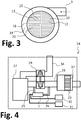
- the Fig. 2 and 3 each show sections through different embodiments of the device 1 Fig. 1 in a direction perpendicular to the axial direction arranged cutting direction.
- the tangentially arranged inflow connection 3 and the deflecting element 18, the housing 38, the cylindrical gap 19 and the central chamber 20 can also be seen.
- the first impingement region 14 and the second impingement region 15 Fig. 2 the second impingement region 15 is arranged concentrically around the first impingement region 14.
- an alternative embodiment is selected, in which the first impingement region 14 and the second impingement region 15 each form quarter pieces of a circular base surface.
- first impact area 14 for ammonia precursor solution can be achieved by a suitable embodiment of the adding device and in particular the nozzle of the adding device.
- first coating 12 is provided which serves to convert the ammonia precursor solution into ammonia.
- second coating 13 is provided, which serves for the thermal conversion of the fuel.
- Fig. 4 shows a motor vehicle 24, comprising an internal combustion engine 27 and an exhaust gas treatment device 23 for cleaning the exhaust gases of the internal combustion engine 27, which is connected via an exhaust pipe 26 to the internal combustion engine 27.
- the internal combustion engine 27 also has an intake line 34, via which the internal combustion engine 27 draws in air (from the environment).
- the motor vehicle 24 also has a turbocharger 29 with which the intake air of the internal combustion engine 27 can be charged or compressed.
- the turbocharger 29 is driven by the exhaust gases flowing through the exhaust pipe 26. In the exhaust gas flow direction in front of the turbocharger 29 branches off a line branch 25 from the exhaust pipe 26, which leads to a device 1 described.
- the ammonia generated by the device 1 is added to the exhaust passage 26 via a metering line 35 in the exhaust gas flow direction behind the turbocharger 29, so that the generated ammonia can be used in the exhaust gas treatment device 23 for exhaust gas purification.
- an SCR catalyst 37 is arranged, can be reacted with the nitrogen oxide compounds in the exhaust gas of the internal combustion engine 27 together with the ammonia from the device 1.
- the device 1 is supplied with fuel from a fuel tank 31 and ammonia precursor solution from a precursor solution tank 30.
- the described device ensures the particularly reliable provision of ammonia for an exhaust gas treatment device even at particularly low exhaust gas temperatures. At the same time a particularly low demand for energy is necessary and ammonia can be kept ready in the form of an ammonia precursor solution and converted from the device to ammonia.
- the device is particularly suitable for cleaning diesel exhaust gases of internal combustion engines, which are operated much in the partial load range.
Landscapes
- Engineering & Computer Science (AREA)
- Chemical & Material Sciences (AREA)
- Chemical Kinetics & Catalysis (AREA)
- Combustion & Propulsion (AREA)
- Mechanical Engineering (AREA)
- General Engineering & Computer Science (AREA)
- Health & Medical Sciences (AREA)
- Toxicology (AREA)
- Exhaust Gas After Treatment (AREA)
Description
- Die Erfindung betrifft eine Vorrichtung zur Erzeugung von Ammoniak aus einer Ammoniak-Vorläuferlösung. Eine derartige Vorrichtung kann beispielsweise dazu verwendet werden, um Ammoniak zu erzeugen, der für die Abgasreinigung in einer Abgasbehandlungsvorrichtung genutzt wird. Abgasbehandlungsvorrichtungen in denen zur Abgasreinigung Ammoniak genutzt wird, werden beispielsweise häufig zur Reinigung der Abgase von Diesel-Verbrennungskraftmaschinen in Kraftfahrzeugen verwendet. Mit Hilfe des Ammoniaks werden Stickstoffoxidverbindungen im Abgas der Verbrennungskraftmaschine reduziert. Als Ammoniak-Vorläuferlösung wird typischerweise Harnstoff-Wasser-Lösung verwendet. Eine solche Ammoniak-Vorläuferlösung hat im Gegensatz zu Ammoniak den Vorteil, dass sie unproblematisch in einem Tank gelagert werden kann. Besonders häufig wird eine Harnstoff-Wasser-Lösung mit einem Harnstoffgehalt von 32,5 % verwendet, die unter dem Handelsnamen AdBlue® erhältlich ist.
- Die Umsetzung von Ammoniak-Vorläuferlösung in Ammoniak erfordert regelmäßig besondere technische Maßnahmen. Ammoniak entsteht aus der Ammoniak-Vorläuferlösung beispielsweise bei bestimmten Temperaturen. Besonders gut findet die Umsetzung in einem Temperaturbereich zwischen 200 °C und 550 °C statt.
- Der Temperaturbereich zur Umsetzung von Ammoniak-Vorläuferlösung in Ammoniak kann durch die Anwesenheit von Katalysatoren erweitert und insbesondere abgesenkt werden, so dass die Umsetzung sogar in einem Temperaturbereich zwischen 140 °C und 250 °C stattfinden kann. Die thermische Umsetzung von Ammoniak-Vorläuferlösung in Ammoniak wird üblicherweise als Thermolyse oder als thermolytische Umsetzung bezeichnet. Wenn die Umsetzung zusätzlich durch einen Katalysator unterstützt wird, spricht man von der Hydrolyse oder hydrolytischer Umsetzung.
- In jedem Fall muss die Ammoniak-Vorläuferlösung erwärmt werden, um zu Ammoniak umgesetzt zu werden. Dafür wird Wärmeenergie benötigt. Üblicherweise wird die Ammoniak-Vorläuferlösung daher in die Abgase einer Verbrennungskraftmaschine direkt zugegeben. Dann erfolgt die Erwärmung durch die Abgase. Hierbei besteht allerdings das Problem, dass insbesondere bei Diesel-Verbrennungskraftmaschinen die Abgase häufig relativ niedrige Temperaturen aufweisen und daher (zumindest in vielen Lastzuständen des Dieselmotors, insbesondere auch im Leerlauf) nicht ausreichend thermische Energie bereitstellen können, um Ammoniak-Vorläuferlösung effektiv in Ammoniak umzusetzen. Soweit möglich wurde dann so vorgegangen, dass eine Dosierung von Ammoniak in diesen Zeiträumen vermieden wurde. Falls dies nicht möglich war, wurde diesem Problem in der Vergangenheit regelmäßig mit Hilfe von geeigneten Maßnahmen zur Temperaturerhöhung in einer Abgasbehandlungsvorrichtung begegnet. Besonders häufig erfolgt das Beheizen der Abgase mit Hilfe einer elektrischen Heizung. Eine weitere bekannte Methode zur Temperaturerhöhung der Abgase ist das bewusste Verschieben des Betriebspunktes der Verbrennungskraftmaschine, so dass die Verbrennungskraftmaschine Abgase mit höheren Temperaturen erzeugt. Hierbei ist es allerdings problematisch, dass sich insbesondere dann, wenn Ammoniak-Vorläuferlösung nicht vollständig zu Ammoniak umgesetzt wird, Ablagerungen der Ammoniak-Vorläuferlösung in der Abgasbehandlungsvorrichtung bilden können. Solche Ablagerungen können die Abgasreinigung (dauerhaft) negativ beeinträchtigen, den Wirkungsgrad und Verbrauch verschlechtern und/oder die Abgasbehandlungsvorrichtung sogar beschädigen. Darüber hinaus kann es passieren, dass die Abgastemperatur zu niedrig ist, um durch die beschriebenen bekannten Maßnahmen zur Temperaturerhöhung die Abgastemperatur für die Umsetzung von Ammoniak-Vorläuferlösung in Ammoniak ausreichend zu erhöhen. Dies gilt insbesondere für Kaltstartphasen einer Verbrennungskraftmaschine, weil die Abgase der Verbrennungskraftmaschine in Kaltstartphasen von der thermischen Masse der Verbrennungskraftmaschine und der Abgasbehandlungsvorrichtung stark abgekühlt wird.
- Ein Abgasbehandlungssystem, mit dem Abgas unter Verwendung von Harnstoff-Wasser-Lösung und Kraftstoff behandelt erden kann, ist aus der
EP 2 295 755 A2 bekannt. - Es ist Aufgabe der vorliegenden Erfindung, eine gegenüber dem Stand der Technik verbesserte Vorrichtung zur Erzeugung von Ammoniak aus einer Ammoniak-Vorläuferlösung anzugeben, die insbesondere in der Lage ist, Ammoniak weitgehend unabhängig von den in einer Abgasbehandlungsvorrichtung vorherrschenden Temperaturen bereitzustellen.
- Diese Aufgaben werden gelöst mit einer Vorrichtung gemäß den Merkmalen des Patentanspruchs 1. Weitere vorteilhafte Ausgestaltungen der Erfindung sind in den abhängigen Patentansprüchen angegeben. Die in den Patentansprüchen einzeln angeführten Merkmale sind in beliebiger, technologisch sinnvoller Weise miteinander kombinierbar und können durch erläuternde Sachverhalte aus der Beschreibung ergänzt werden, wobei weitere Ausführungsvarianten der Erfindung aufgezeigt werden.
- Die Erfindung betrifft eine Vorrichtung zur Erzeugung von Ammoniak aus einer Ammoniak-Vorläuferlösung, aufweisend einem Reaktionsraum mit einem Einströmanschluss, durch welchen ein Abgasstrom in den Reaktionsraum einströmen kann, mit einem Ausströmanschluss, durch welchen ein ammoniakhaltiger Gasstrom den Reaktionsraum verlassen kann, und mit einer Zugabevorrichtung, mit welcher dem Reaktionsraum wahlweise eine Ammoniak-Vorläuferlösung oder ein Brennstoff zugegeben werden kann.
- Die Vorrichtung ist insbesondere als ein Bauteil konzipiert, welches extern bzw. benachbart einer Abgasleitung mit dem Hauptabgasstrom einer Verbrennungskraftmaschine positioniert ist. Die Vorrichtung ist typischerweise an einen Lei tungsabzweig angeschlossen, der von einer Abgasleitung einer Abgasbehandlungsvorrichtung einer Verbrennungskraftmaschine abzweigt. Dieser Leitungsabzweig mündet dann in den Einströmanschluss der Vorrichtung ein. Vorzugsweise zweigt der Leitungsabzweig in Abgasströmungsrichtung vor einem in der Abgasleitung integrierten Abgasturbolader von der Abgasbehandlungsvorrichtung ab. An dem Ausströmanschluss der Vorrichtung ist typischerweise eine Zugabelei tung angeschlossen, über die der von der Vorrichtung erzeugte ammoniakhaltige Gasstrom der Abgasbehandlungsvorrichtung zugegeben wird. Die Zugabeleitung mündet vorzugsweise in Abgasströmungsrichtung hinter dem Turbolader in die Abgasbehandlungsvorrichtung der Verbrennungskraftmaschine ein. Besonders bevorzugt ist die Vorrichtung damit in einem Abgas-Bypass integriert, der den Turbolader überbrückt. Dies hat den Vorteil, dass zwischen dem Einströmanschluss und dem Ausströmanschluss ein Druckunterschied anliegt, welcher dafür sorgt, dass die in den Einströmanschluss eingeleiteten Abgase mit einem Druckgefälle durch die Vorrichtung hindurch gedrückt werden.
- Mit dem Reaktionsraum ist (mindestens) ein Hohlraum innerhalb der Vorrichtung gemeint, in welchem die Umsetzungsreaktion von Ammoniak-Vorläuferlösung in Ammoniak erfolgt. Der Reaktionsraum kann eine Komponente oder verschiedene funktionale Komponenten beinhalten, welche die Umsetzungsreaktion fördern. Dies sind beispielsweise (a) spezielle Katalysatoren, (b) Strukturen, die die Abgasströmung und die Bewegung des Ammoniaks und der Ammoniak-Vorläuferlösung in dem Reaktionsraum beeinflussen und/oder (c) Sensoren, usw.
- Die Zugabevorrichtung umfasst vorzugsweise mindestens eine Düse, mit welcher die Ammoniak-Vorläuferlösung bzw. ein Brennstoff dem Reaktionsraum zugegeben werden können. Vorzugsweise umfasst die Zugabevorrichtung darüber hinaus mindestens ein Ventil, mit welchem die Zugabe von Ammoniak-Vorläuferlösung bzw. von Brennstoff (aktiv) gesteuert werden kann. Das Ventil hat insbesondere die Aufgabe, die Menge an zugeführter Ammoniak-Vorläuferlösung und die Menge an zugeführtem Brennstoff zu steuern. Dies kann beispielsweise durch eine Anpassung der Öffnungszeit des mindestens einen Ventils geschehen. Dabei ist die Dauer der Öffnungszeit proportional zur zugeführten Menge Ammoniak-Vorläuferlösung bzw. proportional zur zugeführten Menge Brennstoff.
- Die Zugabevorrichtung der hier beschriebenen Vorrichtung hat die Eigenschaft, dass mit ihr sowohl Ammoniak-Vorläuferlösung als auch Brennstoff zugegeben werden kann. Hiermit ist gemeint, dass mit der Zugabevorrichtung Ammoniak-Vorläuferlösung und Brennstoff parallel und/oder zeitlich versetzt zueinander dem Reaktionsraum zugeführt werden können.
- Die Ammoniak-Vorläuferlösung wurde weiter oben bereits eingehend beschrieben. Mit einem "Brennstoff" ist insbesondere ein kohlenwasserstoffhaltiges Fluid (Flüssigkeit und/oder Gas) gemeint, welches zusammen mit Sauerstoff verbrannt werden kann und so zu einer starken Temperaturerhöhung beiträgt. Brennstoffe sind beispielsweise die üblichen in Kraftfahrzeugen verwendeten Kraftstoffe, wie z. B. Benzin oder Diesel. Besonders bevorzugt wird als Brennstoff für die Vorrichtung Diesel-Kraftstoff verwendet, weil Diesel-Kraftstoff in Kraftfahrzeugen mit Diesel-Verbrennungskraftmaschine (für die die hier beschriebene Vorrichtung besonders geeignet ist) ohnehin zur Verfügung steht.
- Durch die Zugabevorrichtung der hier behandelten Vorrichtung, die sowohl die Zugabe von Ammoniak-Vorläuferlösung als auch die Zugabe von Brennstoff durchführt, ist es möglich, der Vorrichtung Brennstoff zuzuführen. Brennstoff kann in der Vorrichtung verbrannt werden, so dass die Temperatur in der Vorrichtung erhöht wird und in dem zur Umsetzung von Ammoniak-Vorläuferlösung in Ammoniak notwendigen Temperaturbereich liegt. Die Erhöhung der Temperatur mit Hilfe von Brennstoff ist besonders effizient, weil geeigneter Brennstoff (beispielsweise Diesel-Kraftstoff) in Kraftfahrzeugen regelmäßig ohnehin zur Verfügung steht. Die Temperaturerhöhung erfolgt insbesondere dadurch, dass der Brennstoff auf eine katalytisch aktive Oberfläche aufgegeben wird, wo sich der Brennstoff entzündet. Weiter kann die Temperaturerhöhung auch erreicht werden, indem der Brennstoff mit einer Flamme bzw. einem Funken gezündet wird. Die Temperaturerhöhung mit Hilfe von Brennstoff kann insbesondere erheblich schneller als die Temperaturerhöhung mit Hilfe einer elektrischen Heizung sein. Elektrische Energie steht nämlich in einem Kraftfahrzeug regelmäßig nur begrenzt zur Verfügung, weil elektrische Energie aufwendig mit Hilfe eines Generators erzeugt werden muss.
- Darüber hinaus hat die beschriebene Vorrichtung den großen Vorteil, dass nur ein kleiner (abgezweigter) Teil der Abgase einer Verbrennungskraftmaschine durch die Vorrichtung strömt und in der Vorrichtung erwärmt werden muss, wenn die Abgastemperatur unterhalb der für die Reaktion von Ammoniak-Vorläuferlösung zur Ammoniak notwendigen Temperatur liegt. Die Aufheizung der Abgase in der Vorrichtung kann daher mit einem erheblich reduzierten Energieverbrauch erfolgen als bei Vorrichtungen, die (nur) eine Aufheizung des gesamten Abgasstroms einer Verbrennungskraftmaschine ermöglichen.
- Die Vorrichtung ist besonders vorteilhaft, wenn die Zugabevorrichtung ein Dosierventil umfasst, das eine erste Zuleitung für Ammoniak-Vorläuferlösung und eine zweite Zuleitung für einen Brennstoff aufweist.
- Eine Versorgungsleitung für Ammoniak-Vorläuferlösung kann dann an die erste Zuleitung und eine Versorgungsleitung für Brennstoff an die zweite Zuleitung angeschlossen werden. In der Zugabevorrichtung ist vorzugsweise mindestens ein Ventil vorgesehen, mit welchem die Menge an Brennstoff und die Menge an Ammoniak-Vorläuferlösung, die der Vorrichtung zugeführt wird, jeweils (vorzugsweise getrennt voneinander) genau eingestellt werden können. Besonders bevorzugt beinhaltet die Zugabevorrichtung ein Mehr-Wege-Ventil, mit dem wahlweise Ammoniak-Vorläuferlösung oder Brennstoff zugeführt werden kann. Die Zugabevorrichtung hat vorzugsweise eine gemeinsame Düse, mit welcher sowohl Brennstoff als auch Ammoniak-Vorläuferlösung zugegeben werden kann. Durch die Düse gelangt dann wahlweise Ammoniak-Vorläuferlösung oder Brennstoff in den Reaktionsraum der Vorrichtung. Durch die Zugabe von Brennstoff erfolgt eine Temperaturerhöhung in der Vorrichtung. Sobald die Vorrichtung ausreichend erwärmt ist, wird Ammoniak-Vorläuferlösung zugegeben. Die Ammoniak-Vorläuferlösung wird in der erwärmten Vorrichtung besonders effektiv in Ammoniak umgesetzt. Wenn die Temperatur der Vorrichtung wieder absinken sollte, kann die Zugabe von Ammoniak-Vorläuferlösung wieder beendet werden und es kann erneut Brennstoff zu der Vorrichtung bzw. zu dem Reaktionsraum der Vorrichtung zugegeben werden, so dass die Temperatur wieder auf die für die Erzeugung von Ammoniak notwendige Temperatur erhöht wird und eine erneute Zugabe von Ammoniak-Vorläuferlösung erfolgen kann.
- Besonders vorteilhaft ist die Vorrichtung, wenn in dem Reaktionsraum eine Auftreffstruktur angeordnet ist, auf welche die Zugabevorrichtung ausgerichtet ist und auf welche die zugeführte Ammoniak-Vorläuferlösung auftrifft.
- Eine solche Auftreffstruktur kann beispielsweise in Form eines für den Abgasstrom durchströmbaren Wabenkörpers ausgebildet sein, auf dessen Stirnfläche die Ammoniak-Vorläuferlösung bzw. der Brennstoff auftrifft. Eine solche Auftreffstruktur ist insbesondere derart innerhalb der Vorrichtung angeordnet, dass sie durch den Brennstoff bzw. durch die in die Vorrichtung eintretenden Abgase effektiv erwärmt wird. Vorzugsweise steht die Auftreffstruktur nicht in unmittelbarem Kontakt mit einer Außenwand der Vorrichtung. Die Außenwand der Vorrichtung ist ggf. kühl, weil sie in Kontakt mit der Umgebung steht. Die Auftreffstruktur ist vorzugsweise freitragend oder zumindest abschnittsweise freitragend in dem Reaktionsraum angeordnet. Die Auftreffstruktur ist vorzugsweise so angeordnet, dass sie den Querschnitt des Reaktionsraums zumindest teilweise überspannt.
- Weiterhin ist die Vorrichtung vorteilhaft, wenn die Auftreffstruktur mit einer Beschichtung versehen ist, die sowohl eine Hydrolyse von Ammoniak-Vorläuferlösung in Ammoniak als auch eine exotherme Reaktion von Brennstoff mit Sauerstoff katalysiert.
- Eine derartige Beschichtung umfasst beispielsweise eine der folgenden Komponenten von katalytisch aktivem Material: a) Titandioxid, Aluminiumdioxid und Gold; b) Titandioxid, Platin und Palladium.
- Eine katalytisch wirksame Beschichtung, die eine exotherme Reaktion des Brennstoffs mit Sauerstoff fördert, ist insbesondere vorteilhaft, weil eine solche Beschichtung die Zündtemperatur des Brennstoffs verringert und so vor allem lokale Temperaturspitzen in der Vorrichtung verhindert werden können. Gegebenenfalls kann durch eine katalytisch wirksame Beschichtung auch verhindert werden, dass zur Umsetzung des Brennstoffs in der Vorrichtung eine offene Flamme notwendig ist. Auch so können die thermischen Belastungen innerhalb der Vorrichtung gering gehalten werden. Darüber hinaus ist es möglich, dass zur Initiierung der Verbrennung keine separate bzw. elektrische Zündung erforderlich ist, sondern dass die Umsetzung des Brennstoffs spontan bei Zugabe des Brennstoffs in den Reaktionsraum der Vorrichtung startet. Der für die Verbrennung des Brennstoffs notwendige Sauerstoff tritt üblicherweise mit dem Abgas durch den Einströmanschluss in den Reaktionsraum ein. Insbesondere bei mager betriebenen Diesel-Verbrennungskraftmaschinen tritt üblicherweise ein hoher Sauerstoffanteil im Abgas auf. Alternativ oder zusätzlich zum Sauerstoff können auch nicht voll oxidierte Abgasbestandteile wie Kohlenmonoxid oder Stickstoffmonoxid mit dem Brennstoff umgesetzt werden.
- Weiterhin ist die Vorrichtung vorteilhaft, wenn die Zugabevorrichtung eine gemeinsame Düse umfasst, mit der Ammoniak-Vorläuferlösung und Brennstoff in den Reaktionsraum gesprüht werden kann, wobei die Düse mit Ammoniak-Vorläuferlösung und mit Brennstoff unterschiedliche Sprühbilder erzeugt.
- Mit dem Begriff "gemeinsame" Düse ist hier gemeint, dass sowohl die Ammoniak-Vorläuferlösung als auch der Brennstoff durch dieselbe Düse in den Reaktionsraum gelangt. Mit einem Sprühbild ist hier insbesondere die Form eines Sprühkegels gemeint, der sich ergibt, wenn Ammoniak-Vorläuferlösung bzw. Brennstoff durch eine Austrittsöffnung der Düse austreten. Der verwendete Brennstoff und die Ammoniak-Vorläuferlösung können unterschiedliche strömungstechnische Eigenschaften aufweisen. Insbesondere im Hinblick auf die Viskosität, die Dichte, die Temperaturkapazität und/oder die Oberflächenspannung unterscheiden sich der verwendete Brennstoff und die Ammoniak-Vorläuferlösung regelmäßig stark. Es ist daher möglich, eine Düse zur Zugabe von Ammoniak-Vorläuferlösung und Brennstoff so auszulegen, dass das von der Düse erzeugte Sprühbild mit Brennstoff und das von der Düse erzeugte Sprühbild mit Ammoniak-Vorläuferlösung unterschiedlich zueinander sind (z. B. hinsichtlich der Sprührichtung, der Sprühkegel-Aufweitung, der Sprühtropfengröße, usw.).
- Zusätzlich ist es auch möglich, dass Ammoniak-Vorläuferlösung und Brennstoff an der Düse mit unterschiedlichen Drücken bereitgestellt werden. Auch der an der Düse anliegende Druck beeinflusst das Sprühbild an der Düse. Beispielsweise kann die Ammoniak-Vorläuferlösung an der Düse mit einem Druck bis zu 8 bar bereitgestellt werden, während der Brennstoff an der Düse mit einem davon signifikant abweichenden Druck bereitgestellt wird, beispielsweise (in Abhängigkeit eines konkreten Pumpe-Düse-Systems und einer gewünschten Spray-Bildung) mit einem niedrigeren Druck (z. B. kleiner 5 bar) und/oder einem höheren Druck (z. B. mindestens 20 bar, mindestens 50 bar oder sogar mehr als 200 bar). Dann wird der Brennstoff regelmäßig sehr viel feiner zerstäubt als die Ammoniak-Vorläuferlösung. Üblicherweise bildet sich dann für den Brennstoff ein weiter geöffneter Sprühkegel als für die Ammoniak-Vorläuferlösung. Zusätzlich kann auch durch die Konstruktion der Düse die Ausbildung von unterschiedlichen Sprühkegeln begünstigt werden. Dies kann beispielsweise durch geeignete Umlenkungen der Ammoniak-Vorläuferlösung bzw. des Brennstoffs in der Düse erreicht werden. Solche Umlenkungen wirken sich auf die unterschiedlichen Flüssigkeiten (Brennstoff bzw. Ammoniak-Vorläuferlösung) unterschiedlich aus, so dass dies unterschiedliche Sprühbilder begünstigt.
- Es ist möglich, für die Zugabe von Ammoniak-Vorläuferlösung und/oder Brennstoff ein Trägergas einzusetzen, insbesondere Druckluft. Auch damit kann der vorgegebene Druck bei der Zugabe der Ammoniak-Vorläuferlösung und/oder des Brennstoffs beeinflusst bzw. angepasst werden.
- Weiterhin vorteilhaft ist die Vorrichtung, wenn innerhalb des Reaktionsraums unterschiedliche Auftreffbereiche für Ammoniak-Vorläuferlösung und für Brennstoff vorgesehen sind.
Derartige unterschiedliche Auftreffbereiche können beispielsweise durch eine entsprechende zielgerichtete Auslegung der unterschiedlichen Sprühbilder für Ammoniak-Vorläuferlösung und für Brennstoff erreicht werden. Besonders bevorzugt ist es, wenn für Ammoniak-Vorläuferlösung als Sprühbild ein zentraler kegelförmiger Sprühkegel erzeugt wird, der zentral auf eine Auftreffstruktur in der Vorrichtung trifft und für den Brennstoff ein aufgeweiteter Sprühkegel erzeugt wird, bei dem in einem zentralen Bereich kein Brennstoff versprüht wird, so dass sich ein ringförmiger Auftreffbereich für Brennstoff auf der Auftreffstruktur ergibt, wobei der ringförmige Auftreffbereich für Brennstoff um den zentralen Auftreffbereich für Ammoniak-Vorläuferlösung herum angeordnet ist. - Bei einer derartigen Gestaltung der unterschiedlichen Auftreffbereiche für Ammoniak-Vorläuferlösung und für Brennstoff ist es möglich, in den unterschiedlichen Auftreffbereichen jeweils zielgerichtet geeignete, unterschiedliche Beschichtungen auf der Auftreffstruktur vorzusehen, wobei in dem ersten Auftreffbereich, in dem Ammoniak-Vorläuferlösung auf die Auftreffstruktur auftrifft, eine erste katalytisch wirksame Beschichtung vorgesehen ist, die die katalytische Umsetzung von Ammoniak-Vorläuferlösung in Ammoniak fördert, während in dem zweiten Auftreffbereich eine zweite katalytisch wirksame Beschichtung vorgesehen ist, die die Umsetzungsreaktion von Brennstoff zur Wärmeerzeugung fördert.
- Weiterhin ist in dem Reaktionsraum eine elektrische Heizung angeordnet. Durch eine elektrische Heizung kann die Vorrichtung besonders effektiv aufgeheizt werden. Insbesondere ist es möglich, die Vorrichtung auch bei besonders niedrigen Temperaturen aufzuheizen, bei denen die Erzeugung von Wärme mit Hilfe von Brennstoff noch gar nicht möglich wäre, weil beispielsweise eine Mindesttemperatur für die katalytische Umsetzung des Brennstoffs mit Sauerstoff noch nicht erreicht ist.
- Besonders vorteilhaft ist es, wenn die elektrische Heizung zugleich die Auftreffstruktur innerhalb der Vorrichtung bildet. Die erhöhte Temperatur innerhalb der Vorrichtung wird insbesondere im Bereich der Auftreffstruktur benötigt, weil dort eine Abkühlung durch die auftreffende Ammoniak-Vorläuferlösung stattfindet. Darüber hinaus ist gerade auf der Auftreffstruktur eine erhöhte Temperatur erforderlich, um die Umsetzungsreaktion der Ammoniak-Vorläuferlösung zu bewirken. Die elektrische Heizung trägt dazu bei, dass eine Mindesttemperatur und/oder ein Wärmebereich für die Dosierung eingehalten werden kann. Weiter ermöglicht diese infolge des Kontakts mit der Ammoniak-Vorläuferlösung einen schnelleren Wärmetransport in den Tropfen. Gleichzeitig kann eine hohe Turbulenz erzeugt werden, so dass z. B. so genannte "Leidenfrost-Effekte" weitreichend oder sogar vollständig vermieden werden können. Weiter kann so auch eine ausreichend hohe Wärmekapazität bereitgestellt werden, damit die auftreffenden Tropfen selbst keine wesentliche Abkühlung der elektrischen Heizung / Auftreffstruktur bewirken und damit die Umsetzungsreaktion gleichmäßig bzw. schnell gut ablaufen kann.
- Besonders vorteilhaft ist die Vorrichtung, wenn die elektrische Heizung ein elektrisch beheizbarer Wabenkörper ist.
- Ein elektrisch beheizbarer Wabenkörper eignet sich insbesondere, um mit Hilfe einer elektrischen Heizung eine Auftreffstruktur zu bilden, die gleichzeitig für den Abgasstrom durchströmbar ist. Ein elektrischer Wabenkörper kann beispielsweise eine aus metallischen Folien gebildete Heizspirale sein, die einen Querschnitt der Vorrichtung bzw. einen Querschnitt des Reaktionsraums der Vorrichtung überspannt.
- Darüber hinaus ist die Vorrichtung vorteilhaft, wenn der Einströmanschluss tangential an dem Reaktionsraum angeordnet ist.
- Durch eine tangentiale Anordnung des Einströmanschlusses kann gewährleistet werden, dass das in den Einströmanschluss einströmende Abgas innerhalb der Vorrichtung eine Wirbelströmung erzeugt. Diese Wirbelströmung hat einerseits den Vorteil, dass eine besonders gute Durchmischung von Ammoniak-Vorläuferlösung, Brennstoff und Abgas erfolgt. Darüber hinaus zentriert die Wirbelströmung den Brennstoff bzw. die Ammoniak-Vorläuferlösung innerhalb der Vorrichtung und sorgt dafür, dass der Brennstoff bzw. die Ammoniak-Vorläuferlösung nicht oder nur in geringem Maße mit einer Außenwand der Vorrichtung in Berührung kommt. So kann die Bildung von Ablagerungen des Brennstoffs bzw. der Ammoniak-Vorläuferlösung an der Außenwand der Vorrichtung verhindert werden können.
- Weiterhin ist die Vorrichtung vorteilhaft, wenn der Reaktionsraum durch ein zylindrisches Umlenkelement in einen zylindrischen Spalt und eine zentrale Kammer unterteilt ist, wobei der zylindrische Spalt und die zentrale Kammer über einen Umlenkbereich miteinander verbunden sind, wobei der Einströmanschluss an dem zylindrischen Spalt angeordnet ist, der Abgasstrom von dem zylindrischen Spalt durch den Umlenkbereich in die zentrale Kammer geleitet wird und die Zugabevorrichtung die Vorläuferlösung und den Brennstoff durch den Umlenkbereich in einer axialen Richtung in die zentrale Kammer zugibt.
- Die gesamte Vorrichtung hat vorzugsweise ein zylindrisches Gehäuse. Dabei ist an einer Stirnfläche des zylindrischen Gehäuses die Zugabevorrichtung angeordnet, wobei die Zugaberichtung zu diesem zylindrischen Gehäuse in axialer Richtung ausgerichtet ist. An der gegenüberliegenden Stirnseite des zylindrischen Gehäuses ist vorzugsweise der Ausströmanschluss angeordnet. Der Einströmanschluss mündet mit einer tangentialen Richtung durch eine Umfangsfläche in das zylindrische Gehäuse ein. Der Reaktionsraum ist innerhalb des zylindrischen Gehäuses der Vorrichtung angeordnet. Ausgehend von der Zugabevorrichtung in Richtung hin zu dem Ausströmanschluss ist dann das Umlenkelement angeordnet, welches den zylindrischen (ringförmigen) Spalt von der zentralen Kammer des Reaktionsraums abtrennt. Der zylindrische Spalt ist vorzugsweise nur in Richtung hin zu der Zugabevorrichtung geöffnet und auf der gegenüberliegenden Seite verschlossen. Das durch den Einströmanschluss eintretende Abgas tritt daher in der Nähe der Zugabevorrichtung in einem Umlenkbereich von dem zylindrischen Spalt in die zentrale Kammer über. In dem Umlenkbereich existiert vorzugsweise auch noch eine perforierte Blende, wobei die Abgasströmung diese perforierte Blende von dem Weg aus dem zylindrischen Spalt in die zentrale Kammer passiert. Diese perforierte Blende hat vorzugsweise eine große zentrale Öffnung, durch welche die Zugabevorrichtung den Brennstoff bzw. die Ammoniak-Vorläuferlösung in die zentrale Kammer zugibt. Vorzugsweise erstreckt sich der weiter oben beschriebene Sprühkegel der Zugabevorrichtung durch diese zentrale Öffnung. Um die zentrale Öffnung herum sind vorzugsweise eine Vielzahl von kleinen Öffnungen angeordnet, die den Eintritt des Abgases in die zentrale Kammer begünstigen. In axialer Richtung und ausgehend von der Zugabevorrichtung hin zu dem Ausströmanschluss ist (hinter dem Umlenkelement) die bereits beschriebene Auftreffstruktur angeordnet, die den Querschnitt der Vorrichtung und des Reaktionsraums überspannt und die auch eine elektrische Heizung umfassen kann. In axialer Richtung anschließend zur Auftreffstruktur können sich zusätzliche Katalysatorträgerkörper befinden, die zur Umwandlung der Ammoniak-Vorläuferlösung in Ammoniak beitragen. Dort können auch Sensoren und weitere Komponenten angeordnet sein, mit denen die Erzeugung von Ammoniak in der Vorrichtung unterstützt und/oder überwacht werden kann. Ein Sensor der Vorrichtung kann insbesondere einen Temperatursensor und/oder eine Lambda-Sonde, mit welcher ein Sauerstoff-Anteil im Gas bestimmt werden kann, umfassen.
- Das außen angeordnete zylindrische Umlenkelement hat den Vorteil, dass eine thermische Isolierung der zentralen Kammer von der Außenwand der Vorrichtung realisiert ist, so dass die in die zentrale Kammer zugegebene Ammoniak-Vorläuferlösung nicht mit der Außenwand der Vorrichtung in Kontakt treten kann. Darüber hinaus findet durch das zylindrische Umlenkelement eine Erwärmung der zentralen Kammer statt, weil das durch den Einströmanschluss einströmende Abgas zunächst (durch den zylindrischen Spalt) die zentrale Kammer umströmt und erwärmt, bevor es durch den Umlenkbereich in die zentrale Kammer eintritt.
- Weiter wird eine Abgasbehandlungsvorrichtung zur Reinigung der Abgase einer Verbrennungskraftmaschine vorgeschlagen, aufweisend eine hier beschriebene Vorrichtung zur Erzeugung von Ammoniak, wobei die Einströmöffnung über einen Leitungsabzweig an eine Abgasleitung der Abgasbehandlungsvorrichtung angeschlossen ist und die Ausströmöffnung über eine Zugabeleitung an die Abgasleitung angeschlossen ist, wobei durch die Einströmöffnung zwischen 0,1 % und 5,0 % des Abgases aus der Verbrennungskraftmaschine in den Reaktionsraum strömt.
- Wie bereits beschrieben, zweigt der Leitungsabzweig vorzugsweise vor einem Turbolader von der Abgasleitung ab, während die Zugabeleitung nach dem Turbolader in die Abgasleitung einmündet. Aus diesem Grund ist es vorteilhaft, wenn nur ein verhältnismäßig kleiner Abgasstrom aus der Hauptabgasleitung abgezweigt wird und durch den Einströmanschluss in die Vorrichtung strömt. Der Hauptabgasstrom kann dann in dem Turbolader verwendet werden, um mechanische Energie zur Aufladung der Verbrennungskraftmaschine zu erzeugen. Darüber hinaus kann ein derart kleiner Abgasteilstrom zwischen 0,1 % und 5 % des Abgases mit Hilfe des Brennstoffs bzw. mit Hilfe einer elektrischen Heizung besonders effektiv erwärmt werden, weil hierzu verhältnismäßig wenig thermische Energie notwendig ist. In der Abgasbehandlungsvorrichtung ist vorzugsweise ein SCR-Katalysator angeordnet, an dem Stickstoffoxidverbindungen im Abgas unter Zuhilfenahme des erzeugen Ammoniaks zu unschädlichen Substanzen reduziert werden können.
- Eine solche Abgasbehandlungsvorrichtung wird besonders bevorzugt zur Reinigung der Abgase einer Diesel-Verbrennungskraftmaschine verwendet. Die Abgasbehandlungsvorrichtung und die Vorrichtung sind insbesondere auch zur Abgasreinigung in Wasserfahrzeugen, Schienenfahrzeugen, Land- und Baumaschinen usw. geeignet. Besonders geeignet sind die Vorrichtung und die Abgasbehandlungsvorrichtungen in Anwendungen, in denen die Abgase einer Verbrennungskraftmaschine gereinigt werden, die überwiegend im Teillastbereich und im Niedriglastbereich betrieben wird, weil dann besonders häufig niedrige Abgastemperaturen auftreten.
- Die Erfindung sowie das technische Umfeld werden nachfolgend anhand der Figuren näher erläutert. Die Figuren zeigen besonders bevorzugte Ausführungsbeispiele, auf die die Erfindung jedoch nicht begrenzt ist. Insbesondere ist darauf hinzuweisen, dass die Figuren und vor allem die in den Figuren dargestellten Größenverhältnisse nur schematisch sind. Es zeigen:
- Fig. 1:
- eine beschriebene Vorrichtung,
- Fig. 2:
- einen Querschnitt durch eine erste Ausführungsvariante einer beschriebenen Vorrichtung,
- Fig. 3:
- einen Querschnitt durch eine zweite Ausführungsvariante einer beschriebenen Vorrichtung, und
- Fig. 4:
- ein Kraftfahrzeug aufweisend eine beschriebene Vorrichtung.
- In
Fig. 1 ist eine Vorrichtung 1 dargestellt, die ein zylindrisches Gehäuse 38 aufweist. An der einen Stirnseite der zylindrischen Gehäuses 38 der Vorrichtung befindet sich die Zugabevorrichtung 5, über die der Vorrichtung Brennstoff (z. B. Diesel-Kraftstoff) bzw. Ammoniak-Vorläuferlösung (z. B. Harnstoff-Wasser-Lösung) zugeführt werden kann. Die Zugabevorrichtung 5 weist dazu eine erste Zuleitung 7 zur Zugabe von Ammoniak-Vorläuferlösung und eine zweite Zuleitung 8 zur Zugabe von Brennstoff auf. Die Zugabevorrichtung 5 umfasst auch ein Dosierventil 6, mit welchem (wahlweise) der Brennstoff und die Ammoniak-Vorläuferlösung dosiert werden können. Die Zugabevorrichtung 5 gibt den Brennstoff bzw. die Ammoniak-Vorläuferlösung mit einer axialen Richtung 22 in einen Reaktionsraum 2 der Vorrichtung 1 zu. Dabei wird der Brennstoff bzw. die Ammoniak-Vorläuferlösung mit einem Sprühbild 11 gesprüht. - Gegenüberliegend zu der Zugabevorrichtung 5 ist an der Vorrichtung 1 der Ausströmanschluss 4 angeordnet, durch welchen ein ammoniakhaltiger Gasstrom aus der Vorrichtung 1 austreten kann. An der Umfangsfläche der Vorrichtung 1 ist der Einströmanschluss 3 angeordnet, über welchen ein Abgasstrom in die Vorrichtung eintreten kann. Der Reaktionsraum 2 der Vorrichtung 1 ist durch ein Umlenkelement 18 in einen zylindrischen Spalt 19 und eine zentrale Kammer 20 unterteilt. Der zylindrische Spalt 19 und die zentrale Kammer 20 sind im Bereich der Zugabevorrichtung 5 über einen Umlenkbereich 21 miteinander verbunden. In dem Umlenkbereich 21 ist auch eine perforierte Blende 36 vorgesehen, die eine zentrale Öffnung hat, durch welche die Zugabevorrichtung 5 Ammoniak-Vorläuferlösung bzw. Brennstoff in die zentrale Kammer 20 des Reaktionsraums 2 zugeben kann. Die perforierte Blende 36 hat darüber hinaus zusätzliche (um die zentrale Öffnung herum angeordnete) kleinere Öffnungen, durch welche der Abgasstrom in die zentrale Kammer 20 übertreten kann.
- Der Einströmanschluss 3 ist vorzugsweise tangential an der Vorrichtung 1 angeordnet. Dadurch entsteht innerhalb des Reaktionsraums 2 bzw. innerhalb des zylindrischen Spalts 19 und der zentralen Kammer 20 eine Wirbelströmung 28.
- In Abgasströmungsrichtung innerhalb der Vorrichtung 1 ist hinter dem Umlenkelement 18 und der zentralen Kammer 20 eine Auftreffstruktur 9 angeordnet, die einen ersten Auftreffbereich 14 und einen zweiten Auftreffbereich 15 bildet, wobei der erste Auftreffbereich 14 zur Aufnahme von Ammoniak-Vorläuferlösung und der zweite Auftreffbereich 15 zur Aufnahme von Brennstoff vorgesehen ist. Die Auftreffstruktur 9 ist in der vorliegenden Ausführungsvariante einer Vorrichtung 1 als elektrische Heizung 16 und besonders bevorzugt als elektrisch beheizbarer Wabenkörper 17 ausgebildet. In Strömungsrichtung hinter der Auftreffstruktur 9 ist mindestens ein Katalysatorträgerkörper 32 angeordnet, der Beschichtungen zur chemischen Umsetzung der Ammoniak-Vorläuferlösung und/oder des Brennstoffs beinhalten kann. Zusätzlich ist in der Vorrichtung 1 auch noch ein Sensor 33 vorgesehen, mit welchem die Umsetzung von Ammoniak-Vorläuferlösung zu Ammoniak in der Vorrichtung 1 überwacht werden kann. Der Sensor 33 kann beispielsweise einen Temperatursensor und/oder eine Lambda-Sonde umfassen, mit welcher der Sauerstoffgehalt im Gasstrom bestimmt werden kann.
- Die
Fig. 2 und3 zeigen jeweils Schnitte durch unterschiedliche Ausführungsvarianten der Vorrichtung 1 ausFig. 1 in einer senkrecht zu der axialen Richtung angeordneten Schnittrichtung. Zu erkennen ist jeweils der tangential angeordnete Einströmanschluss 3 sowie das Umlenkelement 18, das Gehäuse 38, der zylindrische Spalt 19 und die zentrale Kammer 20. Auch zu erkennen sind der erste Auftreffbereich 14 und der zweite Auftreffbereich 15. GemäßFig. 2 ist der zweite Auftreffbereich 15 konzentrisch um den ersten Auftreffbereich 14 herum angeordnet. GemäßFig. 3 ist eine alternative Ausführungsvariante gewählt, bei welcher der erste Auftreffbereich 14 und der zweite Auftreffbereich 15 jeweils Viertelstücke einer kreisförmigen Grundfläche bilden. Eine derartige Aufteilung zwischen dem ersten Auftreffbereich 14 für Ammoniak-Vorläuferlösung und dem zweiten Auftreffbereich 15 für Brennstoff kann durch eine geeignete Ausführungsvariante der Zugabevorrichtung und insbesondere der Düse der Zugabevorrichtung erreicht werden. Im ersten Auftreffbereich 14 ist eine erste Beschichtung 12 vorgesehen, die zur Umsetzung der Ammoniak-Vorläuferlösung in Ammoniak dient. Im zweiten Auftreffbereich 15 ist eine zweite Beschichtung 13 vorgesehen, die zur thermischen Umsetzung des Brennstoffs dient. -
Fig. 4 zeigt ein Kraftfahrzeug 24, aufweisend eine Verbrennungskraftmaschine 27 und eine Abgasbehandlungsvorrichtung 23 zur Reinigung der Abgase der Verbrennungskraftmaschine 27, die über eine Abgasleitung 26 mit der Verbrennungskraftmaschine 27 verbunden ist. Die Verbrennungskraftmaschine 27 weist darüber hinaus eine Ansaugleitung 34 auf, über welche die Verbrennungskraftmaschine 27 Luft (aus der Umgebung) ansaugt. Das Kraftfahrzeug 24 weist auch einen Turbolader 29 auf, mit welchem die Ansaugluft der Verbrennungskraftmaschine 27 aufgeladen bzw. verdichtet werden kann. Der Turbolader 29 wird von den durch die Abgasleitung 26 strömenden Abgasen angetrieben. In Abgasströmungsrichtung vor dem Turbolader 29 zweigt ein Leitungsabzweig 25 von der Abgasleitung 26 ab, der zu einer beschriebenen Vorrichtung 1 führt. Der Ammoniak, der von der Vorrichtung 1 erzeugt wurde, wird über eine Zugabeleitung 35 in Abgasströmungsrichtung hinter dem Turbolader 29 der Abgasleitung 26 zugegeben, so dass der erzeugte Ammoniak in der Abgasbehandlungsvorrichtung 23 zur Abgasreinigung verwendet werden kann. In der Abgasbehandlungsvorrichtung 23 ist ein SCR-Katalysator 37 angeordnet, mit dem Stickstoffoxidverbindungen im Abgas der Verbrennungskraftmaschine 27 zusammen mit dem Ammoniak aus der Vorrichtung 1 umgesetzt werden können. Die Vorrichtung 1 wird aus einem Brennstofftank 31 mit Brennstoff und aus einem Vorläuferlösungstank 30 mit Ammoniak-Vorläuferlösung versorgt. - Durch die beschriebene Vorrichtung wird die besonders zuverlässige Bereitstellung von Ammoniak für eine Abgasbehandlungsvorrichtung auch bei besonders niedrigen Abgastemperaturen gewährleistet. Gleichzeitig ist dafür ein besonders geringer Bedarf an Energie notwendig und Ammoniak kann in Form einer Ammoniak-Vorläuferlösung bereitgehalten werden und von der Vorrichtung zu Ammoniak umgesetzt werden. Die Vorrichtung ist insbesondere zur Reinigung von Diesel-Abgasen von Verbrennungskraftmaschinen geeignet, die viel im Teillastbereich betrieben werden.
-
- 1
- Vorrichtung
- 2
- Reaktionsraum
- 3
- Einströmanschluss
- 4
- Ausströmanschluss
- 5
- Zugabevorrichtung
- 6
- Dosierventil
- 7
- erste Zuleitung
- 8
- zweite Zuleitung
- 9
- Auftreffstruktur
- 10
- Düse
- 11
- Sprühbild
- 12
- erste Beschichtung
- 13
- zweite Beschichtung
- 14
- erster Auftreffbereich
- 15
- zweiter Auftreffbereich
- 16
- elektrische Heizung
- 17
- beheizbarer Wabenkörper
- 18
- Umlenkelement
- 19
- zylindrischer Spalt
- 20
- zentrale Kammer
- 21
- Umlenkbereich
- 22
- axiale Richtung
- 23
- Abgasbehandlungsvorrichtung
- 24
- Kraftfahrzeug
- 25
- Leitungsabzweig
- 26
- Abgasleitung
- 27
- Verbrennungskraftmaschine
- 28
- Wirbelströmung
- 29
- Turbolader
- 30
- Vorläuferlösungstank
- 31
- Brennstofftank
- 32
- Katalysatorträgerkörper
- 33
- Sensor
- 34
- Ansaugleitung
- 35
- Zugabeleitung
- 36
- perforierte Blende
- 37
- SCR-Katalysator
- 38
- Gehäuse
Claims (10)
- Vorrichtung (1) zur Erzeugung von Ammoniak aus einer Ammoniak-Vorläuferlösung, aufweisend einem Reaktionsraum (2) mit einem Einströmanschluss (3), durch welchen ein Abgasstrom in den Reaktionsraum (2) einströmen kann, mit einem Ausströmanschluss (4), durch welchen ein ammoniakhaltiger Gasstrom den Reaktionsraum (2) verlassen kann, und mit einer Zugabevorrichtung (5), mit welcher dem Reaktionsraum (2) wahlweise eine Ammoniak-Vorläuferlösung oder ein Brennstoff zugegeben werden kann, wobei in dem Reaktionsraum (2) eine elektrische Heizung (16) angeordnet ist.
- Vorrichtung (1) nach Patentanspruch 1, wobei die Zugabevorrichtung (5) ein Dosierventil (6) umfasst, das eine erste Zuleitung (7) für Ammoniak-Vorläuferlösung und eine zweite Zuleitung (8) für einen Brennstoff aufweist.
- Vorrichtung (1) nach Patentanspruch 1 oder 2, wobei in dem Reaktionsraum (2) eine Auftreffstruktur (9) angeordnet ist, auf welche die Zugabevorrichtung (5) ausgerichtet ist und auf welche die zugeführte Ammoniak-Vorläuferlösung auftrifft.
- Vorrichtung (1) nach Patentanspruch 3, wobei die Auftreffstruktur (9) mit einer Beschichtung (12, 13) versehen ist, die sowohl eine Hydrolyse von Ammoniak-Vorläuferlösung in Ammoniak als auch eine exotherme Reaktion von Brennstoff mit Sauerstoff katalysiert.
- Vorrichtung (1) nach einem der vorhergehenden Patentansprüche, wobei die Zugabevorrichtung (5) eine gemeinsame Düse (10) umfasst, mit der Ammoniak-Vorläuferlösung und Brennstoff in den Reaktionsraum (2) gesprüht werden, wobei die Düse (10) mit Ammoniak-Vorläuferlösung und mit Brennstoff unterschiedliche Sprühbilder (11) erzeugt.
- Vorrichtung (1) nach einem der vorhergehenden Patentansprüche, wobei innerhalb des Reaktionsraums (2) unterschiedliche Auftreffbereiche (14, 15) für Ammoniak-Vorläuferlösung und für Brennstoff vorgesehen sind.
- Vorrichtung (1) nach Patentanspruch 6, wobei die elektrische Heizung (16) ein elektrisch beheizbarer Wabenkörper (17) ist.
- Vorrichtung (1) nach einem der vorhergehenden Patentansprüche, wobei der Einströmanschluss (3) tangential an dem Reaktionsraum (2) angeordnet ist.
- Vorrichtung (1) nach einem der vorhergehenden Patentansprüche, wobei der Reaktionsraum (2) durch ein zylindrisches Umlenkelement (18) in einen zylindrischen Spalt (19) und eine zentrale Kammer (20) unterteilt ist, wobei der zylindrische Spalt (19) und die zentrale Kammer (20) über einen Umlenkbereich (21) miteinander verbunden sind, wobei der Einströmanschluss (3) an dem zylindrischen Spalt (19) angeordnet ist, der Abgasstrom von dem zylindrischen Spalt (19) durch den Umlenkbereich (21) in die zentrale Kammer (20) geleitet wird und die Zugabevorrichtung (5) die Vorläuferlösung und den Brennstoff durch den Umlenkbereich (21) in einer axialen Richtung (22) in die zentrale Kammer (20) zugibt.
- Abgasbehandlungsvorrichtung (23) zur Reinigung der Abgase einer Verbrennungskraftmaschine (27) aufweisend eine Vorrichtung (1) zur Erzeugung von Ammoniak nach einem der vorhergehenden Patentansprüche, wobei der Einströmanschluss (3) über einen Leitungsabzweig (25) an eine Abgasleitung (26) der Abgasbehandlungsvorrichtung (23) angeschlossen ist und der Ausströmanschluss (4) über eine Zugabeleitung (35) an die Abgasleitung (26) angeschlossen ist, wobei durch den Einströmanschluss (3) zwischen 0,1 Prozent und 5 Prozent des Abgases aus der Verbrennungskraftmaschine (27) in den Reaktionsraum (2) strömt.
Applications Claiming Priority (2)
| Application Number | Priority Date | Filing Date | Title |
|---|---|---|---|
| DE102014108875.1A DE102014108875A1 (de) | 2014-06-25 | 2014-06-25 | Vorrichtung zur Erzeugung von Ammoniak |
| PCT/EP2015/062400 WO2015197331A1 (de) | 2014-06-25 | 2015-06-03 | Vorrichtung zur erzeugung von ammoniak |
Publications (2)
| Publication Number | Publication Date |
|---|---|
| EP3161286A1 EP3161286A1 (de) | 2017-05-03 |
| EP3161286B1 true EP3161286B1 (de) | 2019-02-20 |
Family
ID=53442734
Family Applications (1)
| Application Number | Title | Priority Date | Filing Date |
|---|---|---|---|
| EP15730420.5A Not-in-force EP3161286B1 (de) | 2014-06-25 | 2015-06-03 | Vorrichtung zur erzeugung von ammoniak |
Country Status (4)
| Country | Link |
|---|---|
| US (1) | US20170218821A1 (de) |
| EP (1) | EP3161286B1 (de) |
| DE (1) | DE102014108875A1 (de) |
| WO (1) | WO2015197331A1 (de) |
Families Citing this family (1)
| Publication number | Priority date | Publication date | Assignee | Title |
|---|---|---|---|---|
| DE102018105514A1 (de) | 2018-03-09 | 2019-09-12 | Oberland Mangold Gmbh | Verfahren und Vorrichtung zum Reduzieren der Stickoxide im Abgas eines Verbrennungsmotors |
Family Cites Families (13)
| Publication number | Priority date | Publication date | Assignee | Title |
|---|---|---|---|---|
| DE4203807A1 (de) * | 1990-11-29 | 1993-08-12 | Man Nutzfahrzeuge Ag | Vorrichtung zur katalytischen no(pfeil abwaerts)x(pfeil abwaerts)-reduktion |
| DE4230056A1 (de) * | 1992-09-08 | 1994-03-10 | Man Nutzfahrzeuge Ag | Zerstäubereinrichtung |
| DE19922959A1 (de) * | 1999-05-19 | 2000-11-23 | Daimler Chrysler Ag | Abgasreinigungsanlage mit Stickoxidreduktion unter Reduktionsmittelzugabe |
| DE10206028A1 (de) * | 2002-02-14 | 2003-08-28 | Man Nutzfahrzeuge Ag | Verfahren und Vorrichtung zur Erzeugung von Ammoniak |
| DE102006022599B4 (de) * | 2006-05-15 | 2011-02-10 | Continental Automotive Gmbh | Verfahren und Vorrichtung zum Betreiben einer Brennkraftmaschine |
| US7878183B2 (en) * | 2007-07-17 | 2011-02-01 | Cummins Filtration Ip, Inc. | Apparatus, system, and method to provide air to a doser injector nozzle |
| DE102007049850B4 (de) * | 2007-10-18 | 2011-04-21 | Pierburg Gmbh | Abgasnachbehandlungssystem für eine Verbrennungskraftmaschine |
| JP5251266B2 (ja) * | 2008-06-03 | 2013-07-31 | いすゞ自動車株式会社 | 排気ガス浄化装置及び排気ガス浄化システム |
| DE102009015419A1 (de) * | 2009-03-27 | 2010-09-30 | Emitec Gesellschaft Für Emissionstechnologie Mbh | Verfahren zur Zufuhr von Reduktionsmittel in ein Abgassystem und entsprechendes Abgassystem |
| JP2011064069A (ja) * | 2009-09-15 | 2011-03-31 | Toyota Industries Corp | 排気ガス処理装置 |
| DE102009053950A1 (de) * | 2009-11-19 | 2011-05-26 | Man Nutzfahrzeuge Aktiengesellschaft | Vorrichtung zur Nachbehandlung von Abgasen von Brennkraftmaschinen |
| DE102011005654A1 (de) * | 2011-03-16 | 2012-09-20 | Man Diesel & Turbo Se | Brennkraftmaschine |
| EP2726413B1 (de) * | 2011-07-01 | 2017-03-08 | AlzChem AG | Ammoniakgasgenerator zur erzeugung von ammoniak zur reduzierung von stickoxiden in abgasen |
-
2014
- 2014-06-25 DE DE102014108875.1A patent/DE102014108875A1/de not_active Withdrawn
-
2015
- 2015-06-03 WO PCT/EP2015/062400 patent/WO2015197331A1/de not_active Ceased
- 2015-06-03 US US15/321,405 patent/US20170218821A1/en not_active Abandoned
- 2015-06-03 EP EP15730420.5A patent/EP3161286B1/de not_active Not-in-force
Non-Patent Citations (1)
| Title |
|---|
| None * |
Also Published As
| Publication number | Publication date |
|---|---|
| DE102014108875A1 (de) | 2015-12-31 |
| WO2015197331A1 (de) | 2015-12-30 |
| EP3161286A1 (de) | 2017-05-03 |
| US20170218821A1 (en) | 2017-08-03 |
Similar Documents
| Publication | Publication Date | Title |
|---|---|---|
| EP2326807B1 (de) | Abgasreinigungssystem für dieselmotoren | |
| DE102014110592B4 (de) | Nachbehandlungskomponente | |
| EP3161285B1 (de) | Vorrichtung zur erzeugung von ammoniak zur abgasnachbehandlung | |
| DE102010021438B4 (de) | Abgasnachbehandlungsvorrichtung | |
| DE112012006960B4 (de) | Abgasanlage-Mischeinrichtung mit Impaktor | |
| EP2606208B1 (de) | Kompakte abgasbehandlungseinheit mit reaktionsmittelzugabe | |
| DE102019114555B4 (de) | Dieselemissionsfluidinjektor-mischer | |
| EP2574750B1 (de) | Misch- und/oder Verdampfungseinrichtung | |
| DE102009026240A1 (de) | Gasturbinenverbrennungsabgas-Sprühkühlung zur NOx-Steuerung unter Anwendung selektiver katalytischer Reduktionsvorgänge | |
| EP1900916A2 (de) | Abgasnachbehandlungssystem | |
| DE102009053950A1 (de) | Vorrichtung zur Nachbehandlung von Abgasen von Brennkraftmaschinen | |
| EP1985819A2 (de) | Abgasnachbehandlungssystem | |
| EP1562691A2 (de) | Abgasanlage | |
| EP2148053B1 (de) | Katalysatoranordnung zur Reinigung eines Abgasstroms | |
| EP3247889B1 (de) | Abgasreinigungskomponente zur reinigung der abgase einer verbrennungskraftmaschine | |
| DE102015204296A1 (de) | Kompaktes zylindrisches SCR-System zur Reduktion von Stickstoffoxiden im sauerstoffreichen Abgas von Verbrennungsmotoren mit 500 bis 4500 kW | |
| EP2334916B1 (de) | Anordnung und verfahren zur abgasreinigung mittels eines reduktionsmittels | |
| DE102015208016A1 (de) | Abgasnachbehandlungs-System für eine Brennkraftmaschine, Brennkraftmaschine mit einem Abgasnachbehandlungs-System und Verwendung einer Luftstromdüse | |
| DE102013203360A1 (de) | Steuersystem zur reduzierung von distickstoffmonoxid ("n2o") nach einem anspringen einer vorrichtung für selektive katalytische reduktion ("scr") | |
| WO2000008314A1 (de) | Abgasanlage mit einer vorrichtung zur katalytischen nox-reduktion und einem aus fasern bestehenden katalysatorträgerkörper | |
| DE102013215632A1 (de) | Abgasbehandlungssystem für einen Verbrennungsmotor | |
| DE102014108875A1 (de) | Vorrichtung zur Erzeugung von Ammoniak | |
| EP2325450B1 (de) | Vorrichtung zur Nachbehandlung von Abgasen einer Brennkraftmaschine | |
| DE102019212883A1 (de) | Mischvorrichtung | |
| DE102020103074A1 (de) | System zur Einbringung von Reduktionsmittel in ein Abgassystem |
Legal Events
| Date | Code | Title | Description |
|---|---|---|---|
| STAA | Information on the status of an ep patent application or granted ep patent |
Free format text: STATUS: THE INTERNATIONAL PUBLICATION HAS BEEN MADE |
|
| PUAI | Public reference made under article 153(3) epc to a published international application that has entered the european phase |
Free format text: ORIGINAL CODE: 0009012 |
|
| STAA | Information on the status of an ep patent application or granted ep patent |
Free format text: STATUS: REQUEST FOR EXAMINATION WAS MADE |
|
| 17P | Request for examination filed |
Effective date: 20161220 |
|
| AK | Designated contracting states |
Kind code of ref document: A1 Designated state(s): AL AT BE BG CH CY CZ DE DK EE ES FI FR GB GR HR HU IE IS IT LI LT LU LV MC MK MT NL NO PL PT RO RS SE SI SK SM TR |
|
| AX | Request for extension of the european patent |
Extension state: BA ME |
|
| DAV | Request for validation of the european patent (deleted) | ||
| DAX | Request for extension of the european patent (deleted) | ||
| GRAP | Despatch of communication of intention to grant a patent |
Free format text: ORIGINAL CODE: EPIDOSNIGR1 |
|
| STAA | Information on the status of an ep patent application or granted ep patent |
Free format text: STATUS: GRANT OF PATENT IS INTENDED |
|
| INTG | Intention to grant announced |
Effective date: 20180220 |
|
| GRAS | Grant fee paid |
Free format text: ORIGINAL CODE: EPIDOSNIGR3 |
|
| GRAA | (expected) grant |
Free format text: ORIGINAL CODE: 0009210 |
|
| STAA | Information on the status of an ep patent application or granted ep patent |
Free format text: STATUS: THE PATENT HAS BEEN GRANTED |
|
| AK | Designated contracting states |
Kind code of ref document: B1 Designated state(s): AL AT BE BG CH CY CZ DE DK EE ES FI FR GB GR HR HU IE IS IT LI LT LU LV MC MK MT NL NO PL PT RO RS SE SI SK SM TR |
|
| REG | Reference to a national code |
Ref country code: GB Ref legal event code: FG4D Free format text: NOT ENGLISH |
|
| REG | Reference to a national code |
Ref country code: CH Ref legal event code: EP |
|
| REG | Reference to a national code |
Ref country code: DE Ref legal event code: R096 Ref document number: 502015008016 Country of ref document: DE |
|
| REG | Reference to a national code |
Ref country code: AT Ref legal event code: REF Ref document number: 1098469 Country of ref document: AT Kind code of ref document: T Effective date: 20190315 |
|
| REG | Reference to a national code |
Ref country code: IE Ref legal event code: FG4D Free format text: LANGUAGE OF EP DOCUMENT: GERMAN |
|
| REG | Reference to a national code |
Ref country code: NL Ref legal event code: MP Effective date: 20190220 |
|
| REG | Reference to a national code |
Ref country code: LT Ref legal event code: MG4D |
|
| PG25 | Lapsed in a contracting state [announced via postgrant information from national office to epo] |
Ref country code: FI Free format text: LAPSE BECAUSE OF FAILURE TO SUBMIT A TRANSLATION OF THE DESCRIPTION OR TO PAY THE FEE WITHIN THE PRESCRIBED TIME-LIMIT Effective date: 20190220 Ref country code: LT Free format text: LAPSE BECAUSE OF FAILURE TO SUBMIT A TRANSLATION OF THE DESCRIPTION OR TO PAY THE FEE WITHIN THE PRESCRIBED TIME-LIMIT Effective date: 20190220 Ref country code: NL Free format text: LAPSE BECAUSE OF FAILURE TO SUBMIT A TRANSLATION OF THE DESCRIPTION OR TO PAY THE FEE WITHIN THE PRESCRIBED TIME-LIMIT Effective date: 20190220 Ref country code: SE Free format text: LAPSE BECAUSE OF FAILURE TO SUBMIT A TRANSLATION OF THE DESCRIPTION OR TO PAY THE FEE WITHIN THE PRESCRIBED TIME-LIMIT Effective date: 20190220 Ref country code: PT Free format text: LAPSE BECAUSE OF FAILURE TO SUBMIT A TRANSLATION OF THE DESCRIPTION OR TO PAY THE FEE WITHIN THE PRESCRIBED TIME-LIMIT Effective date: 20190620 Ref country code: NO Free format text: LAPSE BECAUSE OF FAILURE TO SUBMIT A TRANSLATION OF THE DESCRIPTION OR TO PAY THE FEE WITHIN THE PRESCRIBED TIME-LIMIT Effective date: 20190520 |
|
| PG25 | Lapsed in a contracting state [announced via postgrant information from national office to epo] |
Ref country code: RS Free format text: LAPSE BECAUSE OF FAILURE TO SUBMIT A TRANSLATION OF THE DESCRIPTION OR TO PAY THE FEE WITHIN THE PRESCRIBED TIME-LIMIT Effective date: 20190220 Ref country code: HR Free format text: LAPSE BECAUSE OF FAILURE TO SUBMIT A TRANSLATION OF THE DESCRIPTION OR TO PAY THE FEE WITHIN THE PRESCRIBED TIME-LIMIT Effective date: 20190220 Ref country code: LV Free format text: LAPSE BECAUSE OF FAILURE TO SUBMIT A TRANSLATION OF THE DESCRIPTION OR TO PAY THE FEE WITHIN THE PRESCRIBED TIME-LIMIT Effective date: 20190220 Ref country code: IS Free format text: LAPSE BECAUSE OF FAILURE TO SUBMIT A TRANSLATION OF THE DESCRIPTION OR TO PAY THE FEE WITHIN THE PRESCRIBED TIME-LIMIT Effective date: 20190620 Ref country code: BG Free format text: LAPSE BECAUSE OF FAILURE TO SUBMIT A TRANSLATION OF THE DESCRIPTION OR TO PAY THE FEE WITHIN THE PRESCRIBED TIME-LIMIT Effective date: 20190520 Ref country code: GR Free format text: LAPSE BECAUSE OF FAILURE TO SUBMIT A TRANSLATION OF THE DESCRIPTION OR TO PAY THE FEE WITHIN THE PRESCRIBED TIME-LIMIT Effective date: 20190521 |
|
| PG25 | Lapsed in a contracting state [announced via postgrant information from national office to epo] |
Ref country code: ES Free format text: LAPSE BECAUSE OF FAILURE TO SUBMIT A TRANSLATION OF THE DESCRIPTION OR TO PAY THE FEE WITHIN THE PRESCRIBED TIME-LIMIT Effective date: 20190220 Ref country code: IT Free format text: LAPSE BECAUSE OF FAILURE TO SUBMIT A TRANSLATION OF THE DESCRIPTION OR TO PAY THE FEE WITHIN THE PRESCRIBED TIME-LIMIT Effective date: 20190220 Ref country code: CZ Free format text: LAPSE BECAUSE OF FAILURE TO SUBMIT A TRANSLATION OF THE DESCRIPTION OR TO PAY THE FEE WITHIN THE PRESCRIBED TIME-LIMIT Effective date: 20190220 Ref country code: RO Free format text: LAPSE BECAUSE OF FAILURE TO SUBMIT A TRANSLATION OF THE DESCRIPTION OR TO PAY THE FEE WITHIN THE PRESCRIBED TIME-LIMIT Effective date: 20190220 Ref country code: SK Free format text: LAPSE BECAUSE OF FAILURE TO SUBMIT A TRANSLATION OF THE DESCRIPTION OR TO PAY THE FEE WITHIN THE PRESCRIBED TIME-LIMIT Effective date: 20190220 Ref country code: AL Free format text: LAPSE BECAUSE OF FAILURE TO SUBMIT A TRANSLATION OF THE DESCRIPTION OR TO PAY THE FEE WITHIN THE PRESCRIBED TIME-LIMIT Effective date: 20190220 Ref country code: EE Free format text: LAPSE BECAUSE OF FAILURE TO SUBMIT A TRANSLATION OF THE DESCRIPTION OR TO PAY THE FEE WITHIN THE PRESCRIBED TIME-LIMIT Effective date: 20190220 Ref country code: DK Free format text: LAPSE BECAUSE OF FAILURE TO SUBMIT A TRANSLATION OF THE DESCRIPTION OR TO PAY THE FEE WITHIN THE PRESCRIBED TIME-LIMIT Effective date: 20190220 |
|
| REG | Reference to a national code |
Ref country code: DE Ref legal event code: R097 Ref document number: 502015008016 Country of ref document: DE |
|
| PG25 | Lapsed in a contracting state [announced via postgrant information from national office to epo] |
Ref country code: SM Free format text: LAPSE BECAUSE OF FAILURE TO SUBMIT A TRANSLATION OF THE DESCRIPTION OR TO PAY THE FEE WITHIN THE PRESCRIBED TIME-LIMIT Effective date: 20190220 Ref country code: PL Free format text: LAPSE BECAUSE OF FAILURE TO SUBMIT A TRANSLATION OF THE DESCRIPTION OR TO PAY THE FEE WITHIN THE PRESCRIBED TIME-LIMIT Effective date: 20190220 |
|
| PLBE | No opposition filed within time limit |
Free format text: ORIGINAL CODE: 0009261 |
|
| STAA | Information on the status of an ep patent application or granted ep patent |
Free format text: STATUS: NO OPPOSITION FILED WITHIN TIME LIMIT |
|
| 26N | No opposition filed |
Effective date: 20191121 |
|
| PG25 | Lapsed in a contracting state [announced via postgrant information from national office to epo] |
Ref country code: MC Free format text: LAPSE BECAUSE OF FAILURE TO SUBMIT A TRANSLATION OF THE DESCRIPTION OR TO PAY THE FEE WITHIN THE PRESCRIBED TIME-LIMIT Effective date: 20190220 |
|
| PG25 | Lapsed in a contracting state [announced via postgrant information from national office to epo] |
Ref country code: SI Free format text: LAPSE BECAUSE OF FAILURE TO SUBMIT A TRANSLATION OF THE DESCRIPTION OR TO PAY THE FEE WITHIN THE PRESCRIBED TIME-LIMIT Effective date: 20190220 |
|
| REG | Reference to a national code |
Ref country code: BE Ref legal event code: MM Effective date: 20190630 |
|
| PG25 | Lapsed in a contracting state [announced via postgrant information from national office to epo] |
Ref country code: TR Free format text: LAPSE BECAUSE OF FAILURE TO SUBMIT A TRANSLATION OF THE DESCRIPTION OR TO PAY THE FEE WITHIN THE PRESCRIBED TIME-LIMIT Effective date: 20190220 |
|
| PG25 | Lapsed in a contracting state [announced via postgrant information from national office to epo] |
Ref country code: IE Free format text: LAPSE BECAUSE OF NON-PAYMENT OF DUE FEES Effective date: 20190603 |
|
| PG25 | Lapsed in a contracting state [announced via postgrant information from national office to epo] |
Ref country code: LU Free format text: LAPSE BECAUSE OF NON-PAYMENT OF DUE FEES Effective date: 20190603 Ref country code: BE Free format text: LAPSE BECAUSE OF NON-PAYMENT OF DUE FEES Effective date: 20190630 |
|
| PG25 | Lapsed in a contracting state [announced via postgrant information from national office to epo] |
Ref country code: FR Free format text: LAPSE BECAUSE OF NON-PAYMENT OF DUE FEES Effective date: 20190630 |
|
| PGFP | Annual fee paid to national office [announced via postgrant information from national office to epo] |
Ref country code: DE Payment date: 20200626 Year of fee payment: 6 Ref country code: CH Payment date: 20200520 Year of fee payment: 6 |
|
| PGFP | Annual fee paid to national office [announced via postgrant information from national office to epo] |
Ref country code: GB Payment date: 20200627 Year of fee payment: 6 |
|
| PG25 | Lapsed in a contracting state [announced via postgrant information from national office to epo] |
Ref country code: CY Free format text: LAPSE BECAUSE OF FAILURE TO SUBMIT A TRANSLATION OF THE DESCRIPTION OR TO PAY THE FEE WITHIN THE PRESCRIBED TIME-LIMIT Effective date: 20190220 |
|
| PG25 | Lapsed in a contracting state [announced via postgrant information from national office to epo] |
Ref country code: MT Free format text: LAPSE BECAUSE OF FAILURE TO SUBMIT A TRANSLATION OF THE DESCRIPTION OR TO PAY THE FEE WITHIN THE PRESCRIBED TIME-LIMIT Effective date: 20190220 Ref country code: HU Free format text: LAPSE BECAUSE OF FAILURE TO SUBMIT A TRANSLATION OF THE DESCRIPTION OR TO PAY THE FEE WITHIN THE PRESCRIBED TIME-LIMIT; INVALID AB INITIO Effective date: 20150603 |
|
| REG | Reference to a national code |
Ref country code: AT Ref legal event code: MM01 Ref document number: 1098469 Country of ref document: AT Kind code of ref document: T Effective date: 20200603 |
|
| PG25 | Lapsed in a contracting state [announced via postgrant information from national office to epo] |
Ref country code: AT Free format text: LAPSE BECAUSE OF NON-PAYMENT OF DUE FEES Effective date: 20200603 |
|
| REG | Reference to a national code |
Ref country code: DE Ref legal event code: R119 Ref document number: 502015008016 Country of ref document: DE |
|
| REG | Reference to a national code |
Ref country code: CH Ref legal event code: PL |
|
| GBPC | Gb: european patent ceased through non-payment of renewal fee |
Effective date: 20210603 |
|
| PG25 | Lapsed in a contracting state [announced via postgrant information from national office to epo] |
Ref country code: LI Free format text: LAPSE BECAUSE OF NON-PAYMENT OF DUE FEES Effective date: 20210630 Ref country code: GB Free format text: LAPSE BECAUSE OF NON-PAYMENT OF DUE FEES Effective date: 20210603 Ref country code: DE Free format text: LAPSE BECAUSE OF NON-PAYMENT OF DUE FEES Effective date: 20220101 Ref country code: CH Free format text: LAPSE BECAUSE OF NON-PAYMENT OF DUE FEES Effective date: 20210630 |
|
| PG25 | Lapsed in a contracting state [announced via postgrant information from national office to epo] |
Ref country code: MK Free format text: LAPSE BECAUSE OF FAILURE TO SUBMIT A TRANSLATION OF THE DESCRIPTION OR TO PAY THE FEE WITHIN THE PRESCRIBED TIME-LIMIT Effective date: 20190220 |