EP3160893B1 - Carriage assembly for materials handling vehicle and method for making same - Google Patents
Carriage assembly for materials handling vehicle and method for making same Download PDFInfo
- Publication number
- EP3160893B1 EP3160893B1 EP15736353.2A EP15736353A EP3160893B1 EP 3160893 B1 EP3160893 B1 EP 3160893B1 EP 15736353 A EP15736353 A EP 15736353A EP 3160893 B1 EP3160893 B1 EP 3160893B1
- Authority
- EP
- European Patent Office
- Prior art keywords
- fork
- bar
- carriage
- supporting bar
- reinforcement
- Prior art date
- Legal status (The legal status is an assumption and is not a legal conclusion. Google has not performed a legal analysis and makes no representation as to the accuracy of the status listed.)
- Active
Links
Images



Classifications
-
- B—PERFORMING OPERATIONS; TRANSPORTING
- B66—HOISTING; LIFTING; HAULING
- B66F—HOISTING, LIFTING, HAULING OR PUSHING, NOT OTHERWISE PROVIDED FOR, e.g. DEVICES WHICH APPLY A LIFTING OR PUSHING FORCE DIRECTLY TO THE SURFACE OF A LOAD
- B66F9/00—Devices for lifting or lowering bulky or heavy goods for loading or unloading purposes
- B66F9/06—Devices for lifting or lowering bulky or heavy goods for loading or unloading purposes movable, with their loads, on wheels or the like, e.g. fork-lift trucks
- B66F9/075—Constructional features or details
- B66F9/12—Platforms; Forks; Other load supporting or gripping members
- B66F9/14—Platforms; Forks; Other load supporting or gripping members laterally movable, e.g. swingable, for slewing or transverse movements
-
- B—PERFORMING OPERATIONS; TRANSPORTING
- B66—HOISTING; LIFTING; HAULING
- B66F—HOISTING, LIFTING, HAULING OR PUSHING, NOT OTHERWISE PROVIDED FOR, e.g. DEVICES WHICH APPLY A LIFTING OR PUSHING FORCE DIRECTLY TO THE SURFACE OF A LOAD
- B66F9/00—Devices for lifting or lowering bulky or heavy goods for loading or unloading purposes
- B66F9/06—Devices for lifting or lowering bulky or heavy goods for loading or unloading purposes movable, with their loads, on wheels or the like, e.g. fork-lift trucks
- B66F9/075—Constructional features or details
-
- B—PERFORMING OPERATIONS; TRANSPORTING
- B66—HOISTING; LIFTING; HAULING
- B66F—HOISTING, LIFTING, HAULING OR PUSHING, NOT OTHERWISE PROVIDED FOR, e.g. DEVICES WHICH APPLY A LIFTING OR PUSHING FORCE DIRECTLY TO THE SURFACE OF A LOAD
- B66F9/00—Devices for lifting or lowering bulky or heavy goods for loading or unloading purposes
- B66F9/06—Devices for lifting or lowering bulky or heavy goods for loading or unloading purposes movable, with their loads, on wheels or the like, e.g. fork-lift trucks
- B66F9/075—Constructional features or details
- B66F9/07504—Accessories, e.g. for towing, charging, locking
-
- B—PERFORMING OPERATIONS; TRANSPORTING
- B66—HOISTING; LIFTING; HAULING
- B66F—HOISTING, LIFTING, HAULING OR PUSHING, NOT OTHERWISE PROVIDED FOR, e.g. DEVICES WHICH APPLY A LIFTING OR PUSHING FORCE DIRECTLY TO THE SURFACE OF A LOAD
- B66F9/00—Devices for lifting or lowering bulky or heavy goods for loading or unloading purposes
- B66F9/06—Devices for lifting or lowering bulky or heavy goods for loading or unloading purposes movable, with their loads, on wheels or the like, e.g. fork-lift trucks
- B66F9/075—Constructional features or details
- B66F9/12—Platforms; Forks; Other load supporting or gripping members
Definitions
- the present invention relates to a carriage assembly to be movably coupled to a mast assembly of a materials handling vehicle comprising a lifting carriage and a fork carriage mounted to the lifting carriage and capable of lateral movement relative to the lifting carriage.
- Materials handling vehicles comprising a carriage assembly movably mounted to a mast assembly of a materials handling vehicle comprising a lifting carriage and a fork carriage mounted on the lifting carriage for lateral movement relative to the lifting carriage.
- a fork-supporting member of the fork carriage may be formed having a fork-receiving hook. It is known to form the fork-supporting member having the fork-receiving hook using a hot rolling process involving a specifically designed hot rolling die. The cost of the die is expensive and the cost of manufacturing the hot rolled material from which a plurality of the fork-supporting members are formed decreases with volume.
- a device according to the prior art is shown in EP1160191A2 .
- a method for manufacturing a fork carriage comprising: providing a fork-supporting bar having first and second fork-receiving hooks, wherein the second fork-receiving hook is of a larger size than the first fork-receiving hook; based on a size of one or more forks desired to be mounted on the fork-supporting bar, positioning the fork-supporting bar such that one of the first and second fork-receiving hooks corresponding to the size of the one or more forks is located outwardly to receive the one or more forks on the one fork-receiving hook; and coupling a reinforcement bar to a first side of the fork-supporting bar opposite a second side near the one fork-receiving hook.
- the method may further comprise selecting a size of the reinforcement bar based on a desired amount of weight to be supported by the one or more forks.
- the fork-supporting bar may comprise an H-shaped bar.
- Coupling the reinforcement bar to the fork-supporting bar may comprise welding the reinforcement bar to the first side of the fork-supporting bar opposite the second side near the one fork-receiving hook.
- the reinforcement bar may be vertically offset relative to the fork-supporting bar such that upper and lower surfaces of the reinforcement bar are vertically offset relative to upper and lower surfaces of the fork-supporting bar.
- Coupling the reinforcement bar to the fork-supporting bar may comprise making a first fillet weld between a side surface of the reinforcement bar and an upper corner of the fork-supporting bar. Coupling may further comprise making a second fillet weld between a bottom surface of the reinforcement bar and a lower side surface and a lower corner of the fork-supporting bar.
- the reinforcement bar may span generally the entire length of the fork-supporting bar.
- the method may further comprise machining notches in the one fork-receiving hook.
- a carriage assembly which is adapted to be movably coupled to a mast assembly of a materials handling vehicle.
- the carriage assembly may comprise: a lifting carriage comprising a lifting carriage upper member including structure for laterally shifting a fork carriage; and the fork carriage mounted on the lifting carriage upper member.
- the fork carriage may comprise fork carriage upper and lower members and fork carriage first and second side members, wherein the upper and lower members may be coupled to the fork carriage first and second side members.
- the upper member may comprise a fork-supporting bar having an outer fork-receiving hook and a reinforcement bar mounted to a first side of the fork-supporting bar opposite a second side near the fork-receiving hook.
- Notches may be provided in the outer fork-receiving hook.
- the reinforcement bar may be vertically offset relative to the fork-supporting bar such that upper and lower surfaces of the reinforcement bar are vertically offset relative to upper and lower surfaces of the fork-supporting bar.
- the reinforcement bar may be coupled to the fork-supporting bar via a first fillet weld located between a side surface of the reinforcement bar and an upper corner of the fork-supporting bar.
- the reinforcement bar may be further coupled to the fork-supporting bar via a second fillet weld located between a bottom surface of the reinforcement bar and a lower side surface and a lower corner of the fork-supporting bar.
- the reinforcement bar may span generally an entire length of the fork-supporting bar.
- the reinforcement bar may have a vertical height greater than a vertical height of the fork-supporting bar.
- the fork-supporting bar may comprise an H-shaped bar.
- a carriage assembly 10 adapted to move vertically up and down along a mast assembly 100 of a materials handling vehicle is illustrated.
- the carriage assembly 10 comprises a lifting carriage 20 coupled to the mast assembly 100 for reciprocal, vertical movement along the mast assembly 100 via a primary cylinder and ram assembly 101 mounted to the mast assembly 100 and a chain (not shown) coupled between the lifting carriage 20 and the primary cylinder and ram assembly 101.
- a fork carriage 30 is mounted to the lifting carriage 20 for lateral movement relative to the lifting carriage 20 and for vertical movement with the lifting carriage 20.
- First and second forks 140A and 140B are mounted onto the fork carriage 30 so as to move with the fork carriage 30.
- the lifting carriage 20 comprises first and second vertical members 20A, 20B and upper and lower support members 20C and 20D, all of which are coupled together via welding so as to move as a unit.
- the lifting carriage upper member 20C comprises first and second separate internal cylinders (not labeled) receiving first and second rams 120 and 122.
- End caps 120A, 122A are provided at opposing ends of the upper member 20C to provide seals between the first and second internal cavities and the first and second rams 120 and 122.
- Hydraulic fluid is separately provided to the first and second internal cylinders to effect movement of the rams 120 and 122 and, hence, the fork carriage 30.
- Polymeric, low-friction, low-wear linear bearings 123 are provided on an upper surface of the upper support member 20C, as shown in Fig. 1 .
- the fork carriage 30, constructed in accordance with a first embodiment of the present invention comprises first and second vertical members 30A, 30B and upper and lower generally horizontal members 30C, 30D, as seen in Figs. 1 and 3 .
- the first, second, and upper and lower members 30A, 30B, 30C and 30D are coupled together via welding to form an integral unit.
- the fork carriage upper member 30C constructed in accordance with a first embodiment of the present invention, comprises a fork-supporting bar, which, in the embodiment illustrated in Figs. 1-6 , comprises an H-shaped bar 200. While not illustrated, it is contemplated that the fork-supporting bar may have a shape other than an H-shape.
- the H-shaped bar 200 is a hot-rolled section. A specifically designed hot rolling die (not shown) is used in manufacturing the H-shaped bar 200, the die for which is expensive to design and produce.
- the H-shaped bar 200 comprises first and second fork-receiving hooks 202 and 204.
- the second fork-receiving hook 204 is sized larger than the first fork-receiving hook 202 such that the second fork-receiving hook 204 is capable of supporting forks that are larger, e.g., Class 3 forks, than those forks adapted to be supported on the first fork-receiving hook 202, e.g., Class 2 forks.
- the fork carriage 30 and its upper member 30C are constructed such that the first fork-receiving hook 202 is positioned outwardly away from the mast assembly 100, as shown in Fig. 6 , so as to allow the forks 140A and 140B to be mounted on the first fork-receiving hook 202.
- the forks 140A and 140B may comprise Class 2 forks having a fork load supporting capacity ranging from about 3000 pounds to about 5500 pounds (ISO Class 2 1000-2500 kg). With reference to Figs.
- a reinforcement bar 50 is welded to the H-shaped bar 200 and positioned adjacent to a side 201 of the H-shaped bar near the second fork-receiving hook 204 to provide structural reinforcement to the H-shaped bar 200.
- the reinforcement bar 50 is vertically offset relative to the H-shaped bar 200 such that reinforcement bar upper and lower surfaces 50A and 50B, respectively, are vertically offset relative to upper and lower surfaces 200A and 200B, respectively, of the H-shaped bar 200, as best seen in Fig. 5 .
- a first fillet weld 60 (shown in Fig. 5 but not in Fig. 4A ) can be formed between a side surface 50C of the reinforcement bar 50 and an upper corner 200C of the H-shaped bar 200.
- a second fillet weld 62 (shown in Fig. 5 but not in Fig. 4A ) can be formed between the bottom surface 50B of the reinforcement bar 50 and a lower side surface 200D and/or a lower corner 200E of the H-shaped bar 200. It is believed that the first and second fillet welds 60 and 62 provide enhanced structural integrity, rigidity and strength to the fork carriage upper member 30C.
- the H-shaped bar 200 is also welded to the fork carriage first and second members 30A and 30B via fillet and groove welds.
- the reinforcement bar 50 has a height H 50 equal to about 63 mm and a width W 50 equal to about 6 mm.
- the height H 200 of the H-shaped bar 200, when measured near the second fork-receiving hook 204, is equal to 60.5 mm in the illustrated embodiment.
- the height H 50 of the reinforcement bar 50 is greater than the height H 200 of the H-shaped bar 200 when measured near the second fork-receiving hook 204, thereby providing increased structural rigidity and strength to the fork carriage upper member 30C.
- a plurality of notches 202A are machined into the first fork-receiving hook 202 to receiving corresponding mating structure (not shown) on the forks 140A and 140B.
- a protection shield 30F is welded to the H-shaped bar 200 and the fork carriage first and second side members 30A and 30B so as to provide protection for the rams 120 and 122 of the lifting carriage upper member 20C, which rams 120 and 122 are positioned behind the protection shield 30F, and to increase the overall strength of the fork carriage upper member 30C.
- the fork carriage 30 and its upper member 30C of the first embodiment are designed to support up to about 4500 pounds.
- the fork carriage 30 is mounted to the lifting carriage 20 by positioning the fork carriage upper member 30C over the lifting carriage upper support member 20C such that an inner cavity 203 of the H-shaped bar 200 is fitted over an upper surface of the support member 20C including the linear bearings 123, as shown in Figs. 1 and 4A .
- the lifting carriage lower support member 20D is provided with first and second polymeric, low-friction, low-wear linear bearings 120D, which are engaged by the fork carriage lower member 30D.
- securement blocks 210 made from steel, are bolted to the lower support member 20D after the fork carriage 30 has been mounted to the lifting carriage 20 to prevent the fork carriage 30 from coming off the lifting carriage 20.
- the H-shaped bar 200 is a hot-rolled section, which is expensive to manufacture.
- the H-shaped bar 200 has been designed with the first and second fork-receiving hooks 202 and 204 to allow the H-shaped bar 200 to be used in the manufacture of separate fork carriages for supporting forks of different sizes and/or different maximum loads.
- a fork carriage 130 constructed in accordance with a second embodiment of the present invention is illustrated in Fig. 4B and comprises a fork carriage upper member 130C.
- the fork carriage 130 further includes first and second vertical members 30A and 30B and a lower member 30D, which are substantially the same as like elements used in the construction of the fork carriage 30 illustrated in Fig. 1 .
- the fork carriage upper member 130C constructed in accordance with the second embodiment of the present invention, comprises a fork-supporting bar, which, in the embodiment illustrated in Fig. 4B , comprises the same H-shaped bar 200 as used in the fork carriage upper member 30C in accordance with a first embodiment shown in Fig. 4A .
- the fork carriage 130 and its upper member 130C are constructed such that the first fork-receiving hook 202 is positioned outwardly away from the mast assembly 100 similar to a first embodiment of the present invention shown in Fig. 6 , to allow the forks 140A and 140B, e.g., Class 2 forks, to be mounted on the first fork-receiving hook 202.
- a reinforcement bar 150 is welded to the H-shaped bar 200 and positioned adjacent to a side of the H-shaped bar near the second fork-receiving hook 204 to provide structural reinforcement to the H-shaped bar 200.
- the reinforcement bar 150 is vertically offset relative to the H-shaped bar 200, as shown in Fig. 4B . Because the reinforcement bar 150 is vertically offset relative to the H-shaped bar 200, a first fillet weld (not shown in Fig. 4B ; similar to a first fillet weld 60 shown in Fig.
- a second fillet weld (not shown in Fig. 4B ; similar to a second fillet weld 62 in Fig. 5 ) can be formed between a bottom surface 150B of the reinforcement bar 150 and a lower side surface 200D and/or a lower corner 200E of the H-shaped bar 200, as seen in Fig. 4B .
- the H-shaped bar 200 is also welded to the fork carriage first and second members 30A and 30B via fillet and groove welds (not shown).
- the reinforcement bar 150 has a height H 150 equal to about 63 mm and a width W 150 equal to about 10 mm. In an alternative embodiment, the width W 150 is equal to 13 mm.
- the reinforcement bar 150 has a width W 150 greater than that of the width W 50 of the reinforcement bar 50 of the first embodiment shown in Fig. 4A , and hence, the reinforcement bar 150 of the second embodiment is larger than the reinforcement bar 50 of the first embodiment.
- the larger reinforcement bar 150 allows the fork carriage 130 and its upper member 130C to support a larger load, e.g., up to 5500 pounds in the illustrated embodiment, than the upper member 30C of the first embodiment.
- the reinforcement bar 150 spans generally the entire length of the H-shaped bar 200 in the illustrated embodiment.
- a plurality of notches 202A are machined into the first fork-receiving hook 202 to receiving corresponding mating structure (not shown) on the forks 140A and 140B.
- a protection shield 30F is welded to the H-shaped bar 200 and the fork carriage first and second side members 30A and 30B, so as to provide protection for the rams 120 and 122 of the lifting carriage upper member 20C, which rams 120 and 122 are positioned behind the protection shield 30F, and to increase the overall strength of the fork carriage upper member 130C.
- a fork carriage 230 constructed in accordance with a third embodiment of the present invention is illustrated in Fig. 4C and comprises a fork carriage upper member 230C.
- the fork carriage 230 further includes first and second vertical members 30A and 30B and a lower member 30D, which are substantially the same as like elements used in the construction of the fork carriage 30 in accordance with a first embodiment shown in Fig. 4A .
- the fork carriage upper member 230C constructed in accordance with the third embodiment of the present invention, comprises a fork-supporting bar, which, in the embodiment illustrated in Fig. 4C , comprises the same H-shaped bar 200 used in the fork carriage upper members 30C and 130C in accordance with first and second embodiments shown in Fig. 4A and 4B , respectively.
- the forks adapted to be mounted on the second fork-receiving hook 204 may comprise Class 3 forks having a fork load supporting capacity of from about 5500 pounds to about 10,000 pounds (ISO Class 3 2501-4999 kg).
- a reinforcement bar 250 is welded to the H-shaped bar 200 and positioned adjacent to a side of the H-shaped bar near the first fork-receiving hook 202 to provide structural reinforcement to the H-shaped bar 200.
- the reinforcement bar 250 is vertically offset relative to the H-shaped bar 200. Because the reinforcement bar 250 is vertically offset relative to the H-shaped bar 200, a first fillet weld (not shown in Fig. 4C ; similar to a first fillet weld 60 shown in Fig. 5 ) can be formed between a side surface 250C of the reinforcement bar 150 and an upper corner 200F of the H-shaped bar 200. Further, a second fillet weld (not shown in Fig.
- H-shaped bar 200 is also welded to the fork carriage first and second members 30A and 30B via fillet and groove welds.
- the reinforcement bar 250 has a height H 250 equal to about 63 mm and a width W 250 equal to about 19 mm.
- the reinforcement bar 250 has a width W 250 greater than that of the width W 150 of the reinforcement bar 150 of the second embodiment shown in Fig. 4B and the width W 50 of the reinforcement bar 50 of the first embodiment shown in Fig. 4A .
- the reinforcement bar 250 is larger than the reinforcement bar 150 of the second embodiment and the reinforcement bar 50 of the first embodiment.
- the larger reinforcement bar 250 and the larger hook 204 allows the fork carriage 250 and its upper member 230C to support larger forks and a greater load, e.g., up to 6500 pounds in the illustrated embodiment, than the upper members 30C and 130C of the first and second embodiments.
- the reinforcement bar 250 spans generally the entire length of the H-shaped bar 200 in the illustrated embodiment.
- a plurality of notches 204A are machined into the second fork-receiving hook 204 to receiving corresponding mating structure (not shown) on forks to be mounted to the second fork-receiving hook 204.
- a protection shield 30F is welded to the H-shaped bar 200 and the fork carriage first and second side members 30A and 30B, so as to provide protection for the rams 120 and 122 of the lifting carriage upper member 20C, which rams 120 and 122 are positioned behind the protection shield 30F.
Landscapes
- Engineering & Computer Science (AREA)
- Transportation (AREA)
- Structural Engineering (AREA)
- Civil Engineering (AREA)
- Life Sciences & Earth Sciences (AREA)
- Geology (AREA)
- Mechanical Engineering (AREA)
- Forklifts And Lifting Vehicles (AREA)
- Baking, Grill, Roasting (AREA)
Description
- The present invention relates to a carriage assembly to be movably coupled to a mast assembly of a materials handling vehicle comprising a lifting carriage and a fork carriage mounted to the lifting carriage and capable of lateral movement relative to the lifting carriage.
- Materials handling vehicles are known comprising a carriage assembly movably mounted to a mast assembly of a materials handling vehicle comprising a lifting carriage and a fork carriage mounted on the lifting carriage for lateral movement relative to the lifting carriage. A fork-supporting member of the fork carriage may be formed having a fork-receiving hook. It is known to form the fork-supporting member having the fork-receiving hook using a hot rolling process involving a specifically designed hot rolling die. The cost of the die is expensive and the cost of manufacturing the hot rolled material from which a plurality of the fork-supporting members are formed decreases with volume. A device according to the prior art is shown in
EP1160191A2 . - In accordance with a first aspect of the present invention, a method is provided for manufacturing a fork carriage comprising: providing a fork-supporting bar having first and second fork-receiving hooks, wherein the second fork-receiving hook is of a larger size than the first fork-receiving hook; based on a size of one or more forks desired to be mounted on the fork-supporting bar, positioning the fork-supporting bar such that one of the first and second fork-receiving hooks corresponding to the size of the one or more forks is located outwardly to receive the one or more forks on the one fork-receiving hook; and coupling a reinforcement bar to a first side of the fork-supporting bar opposite a second side near the one fork-receiving hook.
- The method may further comprise selecting a size of the reinforcement bar based on a desired amount of weight to be supported by the one or more forks.
- The fork-supporting bar may comprise an H-shaped bar.
- Coupling the reinforcement bar to the fork-supporting bar may comprise welding the reinforcement bar to the first side of the fork-supporting bar opposite the second side near the one fork-receiving hook.
- The reinforcement bar may be vertically offset relative to the fork-supporting bar such that upper and lower surfaces of the reinforcement bar are vertically offset relative to upper and lower surfaces of the fork-supporting bar.
- Coupling the reinforcement bar to the fork-supporting bar may comprise making a first fillet weld between a side surface of the reinforcement bar and an upper corner of the fork-supporting bar. Coupling may further comprise making a second fillet weld between a bottom surface of the reinforcement bar and a lower side surface and a lower corner of the fork-supporting bar.
- The reinforcement bar may span generally the entire length of the fork-supporting bar.
- The method may further comprise machining notches in the one fork-receiving hook.
- In accordance with a second aspect of the present invention, a carriage assembly is provided, which is adapted to be movably coupled to a mast assembly of a materials handling vehicle. The carriage assembly may comprise: a lifting carriage comprising a lifting carriage upper member including structure for laterally shifting a fork carriage; and the fork carriage mounted on the lifting carriage upper member. The fork carriage may comprise fork carriage upper and lower members and fork carriage first and second side members, wherein the upper and lower members may be coupled to the fork carriage first and second side members. The upper member may comprise a fork-supporting bar having an outer fork-receiving hook and a reinforcement bar mounted to a first side of the fork-supporting bar opposite a second side near the fork-receiving hook.
- Notches may be provided in the outer fork-receiving hook.
- The reinforcement bar may be vertically offset relative to the fork-supporting bar such that upper and lower surfaces of the reinforcement bar are vertically offset relative to upper and lower surfaces of the fork-supporting bar.
- The reinforcement bar may be coupled to the fork-supporting bar via a first fillet weld located between a side surface of the reinforcement bar and an upper corner of the fork-supporting bar.
- The reinforcement bar may be further coupled to the fork-supporting bar via a second fillet weld located between a bottom surface of the reinforcement bar and a lower side surface and a lower corner of the fork-supporting bar.
- The reinforcement bar may span generally an entire length of the fork-supporting bar.
- The reinforcement bar may have a vertical height greater than a vertical height of the fork-supporting bar.
- The fork-supporting bar may comprise an H-shaped bar.
- While the specification concludes with claims particularly pointing out and distinctly claiming the present invention, it is believed that the present invention will be better understood from the following description in conjunction with the accompanying Drawing Figures, in which like reference numerals identify like elements, and wherein:
-
Fig. 1 is an exploded view of the carriage assembly of the present invention; -
Fig. 2 is a rear view of the carriage assembly ofFig. 1 ; -
Fig. 3 is a front view of the carriage assembly ofFig. 1 ; -
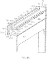
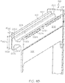
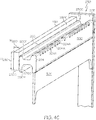
Figs. 4A ,4B , and4C are perspective views of portions of fork carriages and corresponding upper members of first, second, and third embodiments of the present invention; -
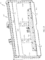
Fig. 5 is a view partially in cross section of a portion of a fork carriage upper member constructed in accordance with the first embodiment of the present invention; and -
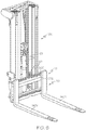
Fig. 6 is a view of a materials handling vehicle including the carriage assembly ofFig. 1 . - In the following detailed description of the preferred embodiments, reference is made to the accompanying drawings that form a part hereof, and in which is shown by way of illustration, and not by way of limitation, specific preferred embodiments in which the invention may be practiced. It is to be understood that other embodiments may be utilized and that changes may be made without departing from the spirit and scope of the present invention.
- With reference to
Figs. 1-6 , acarriage assembly 10 adapted to move vertically up and down along amast assembly 100 of a materials handling vehicle is illustrated. As seen inFig. 6 , thecarriage assembly 10 comprises alifting carriage 20 coupled to themast assembly 100 for reciprocal, vertical movement along themast assembly 100 via a primary cylinder andram assembly 101 mounted to themast assembly 100 and a chain (not shown) coupled between thelifting carriage 20 and the primary cylinder andram assembly 101. Afork carriage 30 is mounted to the liftingcarriage 20 for lateral movement relative to the liftingcarriage 20 and for vertical movement with thelifting carriage 20. First andsecond forks fork carriage 30 so as to move with thefork carriage 30. - With reference to
Figs. 1 and2 , the liftingcarriage 20 comprises first and secondvertical members lower support members 20C and 20D, all of which are coupled together via welding so as to move as a unit. The lifting carriage upper member 20C comprises first and second separate internal cylinders (not labeled) receiving first andsecond rams End caps second rams rams fork carriage 30. Polymeric, low-friction, low-wearlinear bearings 123 are provided on an upper surface of the upper support member 20C, as shown inFig. 1 . - The
fork carriage 30, constructed in accordance with a first embodiment of the present invention, comprises first and secondvertical members horizontal members Figs. 1 and3 . The first, second, and upper andlower members - The fork carriage
upper member 30C, constructed in accordance with a first embodiment of the present invention, comprises a fork-supporting bar, which, in the embodiment illustrated inFigs. 1-6 , comprises an H-shaped bar 200. While not illustrated, it is contemplated that the fork-supporting bar may have a shape other than an H-shape. The H-shaped bar 200 is a hot-rolled section. A specifically designed hot rolling die (not shown) is used in manufacturing the H-shaped bar 200, the die for which is expensive to design and produce. With reference toFigs. 4A-C and5 , the H-shaped bar 200 comprises first and second fork-receivinghooks hook 204 is sized larger than the first fork-receivinghook 202 such that the second fork-receivinghook 204 is capable of supporting forks that are larger, e.g., Class 3 forks, than those forks adapted to be supported on the first fork-receivinghook 202, e.g., Class 2 forks. For example, as illustrated inFig. 4A , the first fork-receivinghook 202 may have a height H1 extending above arecess 206 of about 13 mm and a maximum width W1 = 16 mm. The second fork-receivinghook 204 may have a height H2 extending above therecess 206 equal to about 16 mm and a maximum width W2 = 21 mm. In an alternative embodiment, the first fork-receivinghook 202 may have a maximum width W1 = 20.4 mm, and the second fork-receivinghook 204 may have a maximum width W2 = 27.0, with a corresponding width at the tip of each fork-receivinghook - In accordance with a first embodiment of the present invention, the
fork carriage 30 and itsupper member 30C are constructed such that the first fork-receivinghook 202 is positioned outwardly away from themast assembly 100, as shown inFig. 6 , so as to allow theforks hook 202. Theforks Figs. 4A and5 , areinforcement bar 50 is welded to the H-shapedbar 200 and positioned adjacent to aside 201 of the H-shaped bar near the second fork-receivinghook 204 to provide structural reinforcement to the H-shapedbar 200. In the illustrated embodiment, thereinforcement bar 50 is vertically offset relative to the H-shapedbar 200 such that reinforcement bar upper andlower surfaces lower surfaces bar 200, as best seen inFig. 5 . - Because the
reinforcement bar 50 is vertically offset relative to the H-shapedbar 200, a first fillet weld 60 (shown inFig. 5 but not inFig. 4A ) can be formed between aside surface 50C of thereinforcement bar 50 and an upper corner 200C of the H-shapedbar 200. Further, a second fillet weld 62 (shown inFig. 5 but not inFig. 4A ) can be formed between thebottom surface 50B of thereinforcement bar 50 and alower side surface 200D and/or alower corner 200E of the H-shapedbar 200. It is believed that the first and second fillet welds 60 and 62 provide enhanced structural integrity, rigidity and strength to the fork carriageupper member 30C. The H-shapedbar 200 is also welded to the fork carriage first andsecond members - In the illustrated embodiment as shown in
Fig. 4A , thereinforcement bar 50 has a height H50 equal to about 63 mm and a width W50 equal to about 6 mm. Thereinforcement bar 50 spans generally the entire length L1 of the H-shapedbar 200, wherein L1 = about 900 mm in the illustrated embodiment. The height H200 of the H-shapedbar 200, when measured near the second fork-receivinghook 204, is equal to 60.5 mm in the illustrated embodiment. Hence, the height H50 of thereinforcement bar 50 is greater than the height H200 of the H-shapedbar 200 when measured near the second fork-receivinghook 204, thereby providing increased structural rigidity and strength to the fork carriageupper member 30C. - Further during manufacturing, a plurality of
notches 202A are machined into the first fork-receivinghook 202 to receiving corresponding mating structure (not shown) on theforks - As seen in
Figs. 1 ,4A-4C , and5 , aprotection shield 30F is welded to the H-shapedbar 200 and the fork carriage first andsecond side members rams protection shield 30F, and to increase the overall strength of the fork carriageupper member 30C. Thefork carriage 30 and itsupper member 30C of the first embodiment are designed to support up to about 4500 pounds. - The
fork carriage 30 is mounted to the liftingcarriage 20 by positioning the fork carriageupper member 30C over the lifting carriage upper support member 20C such that aninner cavity 203 of the H-shapedbar 200 is fitted over an upper surface of the support member 20C including thelinear bearings 123, as shown inFigs. 1 and4A . It is noted that the lifting carriagelower support member 20D is provided with first and second polymeric, low-friction, low-wearlinear bearings 120D, which are engaged by the fork carriagelower member 30D. As shown inFigs. 1 and3 , securement blocks 210, made from steel, are bolted to thelower support member 20D after thefork carriage 30 has been mounted to the liftingcarriage 20 to prevent thefork carriage 30 from coming off the liftingcarriage 20. - When the first internal cylinder within the lifting carriage upper support member 20C is supplied with hydraulic fluid, the
first ram 120 is moved outwardly, causing thefork carriage 30 to move laterally to the right inFig. 2 . When the second internal cylinder within the lifting carriage upper support member 20C is supplied with hydraulic fluid, thesecond ram 122 is moved outwardly, causing thefork carriage 30 to move laterally to the left inFig. 2 . When fluid is provided to the first cylinder, fluid is not provided to the second cylinder and vice versa. - As noted above, the H-shaped
bar 200 is a hot-rolled section, which is expensive to manufacture. In order to reduce the expense of designing and producing two separate hot rolling dies to produce two separate fork-supporting bars with different profiles, the H-shapedbar 200 has been designed with the first and second fork-receivinghooks bar 200 to be used in the manufacture of separate fork carriages for supporting forks of different sizes and/or different maximum loads. - A
fork carriage 130 constructed in accordance with a second embodiment of the present invention is illustrated inFig. 4B and comprises a fork carriage upper member 130C. Thefork carriage 130 further includes first and secondvertical members lower member 30D, which are substantially the same as like elements used in the construction of thefork carriage 30 illustrated inFig. 1 . - The fork carriage upper member 130C, constructed in accordance with the second embodiment of the present invention, comprises a fork-supporting bar, which, in the embodiment illustrated in
Fig. 4B , comprises the same H-shapedbar 200 as used in the fork carriageupper member 30C in accordance with a first embodiment shown inFig. 4A . Thefork carriage 130 and its upper member 130C are constructed such that the first fork-receivinghook 202 is positioned outwardly away from themast assembly 100 similar to a first embodiment of the present invention shown inFig. 6 , to allow theforks hook 202. Hence, thesame size forks upper members 30C and 130C of the first and second embodiments. Areinforcement bar 150 is welded to the H-shapedbar 200 and positioned adjacent to a side of the H-shaped bar near the second fork-receivinghook 204 to provide structural reinforcement to the H-shapedbar 200. In the illustrated embodiment, thereinforcement bar 150 is vertically offset relative to the H-shapedbar 200, as shown inFig. 4B . Because thereinforcement bar 150 is vertically offset relative to the H-shapedbar 200, a first fillet weld (not shown inFig. 4B ; similar to afirst fillet weld 60 shown inFig. 5 ) can be formed between a side surface 150C of thereinforcement bar 150 and an upper corner 200C of the H-shapedbar 200. Further, a second fillet weld (not shown inFig. 4B ; similar to a second fillet weld 62 inFig. 5 ) can be formed between abottom surface 150B of thereinforcement bar 150 and alower side surface 200D and/or alower corner 200E of the H-shapedbar 200, as seen inFig. 4B . The H-shapedbar 200 is also welded to the fork carriage first andsecond members - In the second embodiment illustrated in
Fig. 4B , thereinforcement bar 150 has a height H150 equal to about 63 mm and a width W150 equal to about 10 mm. In an alternative embodiment, the width W150 is equal to 13 mm. Thereinforcement bar 150 has a width W150 greater than that of the width W50 of thereinforcement bar 50 of the first embodiment shown inFig. 4A , and hence, thereinforcement bar 150 of the second embodiment is larger than thereinforcement bar 50 of the first embodiment. Thelarger reinforcement bar 150 allows thefork carriage 130 and its upper member 130C to support a larger load, e.g., up to 5500 pounds in the illustrated embodiment, than theupper member 30C of the first embodiment. Thereinforcement bar 150 spans generally the entire length of the H-shapedbar 200 in the illustrated embodiment. - Further during manufacturing, a plurality of
notches 202A are machined into the first fork-receivinghook 202 to receiving corresponding mating structure (not shown) on theforks - A
protection shield 30F is welded to the H-shapedbar 200 and the fork carriage first andsecond side members rams protection shield 30F, and to increase the overall strength of the fork carriage upper member 130C. - A
fork carriage 230 constructed in accordance with a third embodiment of the present invention, is illustrated inFig. 4C and comprises a fork carriageupper member 230C. Thefork carriage 230 further includes first and secondvertical members lower member 30D, which are substantially the same as like elements used in the construction of thefork carriage 30 in accordance with a first embodiment shown inFig. 4A . - The fork carriage
upper member 230C, constructed in accordance with the third embodiment of the present invention, comprises a fork-supporting bar, which, in the embodiment illustrated inFig. 4C , comprises the same H-shapedbar 200 used in the fork carriageupper members 30C and 130C in accordance with first and second embodiments shown inFig. 4A and4B , respectively. However, to allow thefork carriage 230 and itsupper member 230C to support forks larger than theforks 140A, 142A shown inFig. 6 and supported by theupper members 30C and 130C, the H-shaped bar inFig. 4C has been rotated 180 degrees so that the second fork-receivinghook 204 is positioned outwardly away from the mast assembly, to allow the larger forks, e.g., Class 3 forks, to be mounted on the second fork-receivinghook 204. The forks adapted to be mounted on the second fork-receivinghook 204 may comprise Class 3 forks having a fork load supporting capacity of from about 5500 pounds to about 10,000 pounds (ISO Class 3 2501-4999 kg). - A
reinforcement bar 250 is welded to the H-shapedbar 200 and positioned adjacent to a side of the H-shaped bar near the first fork-receivinghook 202 to provide structural reinforcement to the H-shapedbar 200. In the embodiment illustrated inFig. 4C , thereinforcement bar 250 is vertically offset relative to the H-shapedbar 200. Because thereinforcement bar 250 is vertically offset relative to the H-shapedbar 200, a first fillet weld (not shown inFig. 4C ; similar to afirst fillet weld 60 shown inFig. 5 ) can be formed between a side surface 250C of thereinforcement bar 150 and anupper corner 200F of the H-shapedbar 200. Further, a second fillet weld (not shown inFig. 4C ; similar to a second fillet weld 62 shown inFig. 5 ) can be formed between abottom surface 250B of thereinforcement bar 250 and a lower side surface 200G and/or acorner 200H of the H-shapedbar 200, as seen inFig. 4C . The H-shapedbar 200 is also welded to the fork carriage first andsecond members - In the embodiment illustrated in
Fig. 4C , thereinforcement bar 250 has a height H250 equal to about 63 mm and a width W250 equal to about 19 mm. Thereinforcement bar 250 has a width W250 greater than that of the width W150 of thereinforcement bar 150 of the second embodiment shown inFig. 4B and the width W50 of thereinforcement bar 50 of the first embodiment shown inFig. 4A . Hence, thereinforcement bar 250 is larger than thereinforcement bar 150 of the second embodiment and thereinforcement bar 50 of the first embodiment. Thelarger reinforcement bar 250 and thelarger hook 204 allows thefork carriage 250 and itsupper member 230C to support larger forks and a greater load, e.g., up to 6500 pounds in the illustrated embodiment, than theupper members 30C and 130C of the first and second embodiments. Thereinforcement bar 250 spans generally the entire length of the H-shapedbar 200 in the illustrated embodiment. - Further during manufacturing, a plurality of
notches 204A are machined into the second fork-receivinghook 204 to receiving corresponding mating structure (not shown) on forks to be mounted to the second fork-receivinghook 204. - A
protection shield 30F is welded to the H-shapedbar 200 and the fork carriage first andsecond side members rams protection shield 30F.
Claims (15)
- A method of manufacturing a fork carriage (30, 130, 230) comprising:providing a fork-supporting bar (200) having first and second fork-receiving hooks (202, 204), wherein the second fork-receiving hook (204) is of a larger size than the first fork-receiving hook (202);based on a size of one or more forks (140A, 140B) desired to be mounted on the fork-supporting bar (200), positioning the fork-supporting bar (200) such that one of the first and second fork-receiving hooks (202, 204) corresponding to the size of the one or more forks (140A, 140B) is located outwardly to receive the one or more forks (140A, 140B) on the one fork-receiving hook (202, 204); characterised in that the method comprisescoupling a reinforcement bar (50, 150, 250) to a first side of the fork-supporting bar (200) opposite a second side near the one fork-receiving hook.
- The method as set forth in claim 1, further comprising selecting a size of the reinforcement bar (50, 150, 250) based on a desired amount of weight to be supported by the one or more forks (140A, 140B).
- The method as set forth in claim 1, wherein the fork-supporting bar (200) comprises an H-shaped bar.
- The method as set forth in claim 1, wherein coupling the reinforcement bar (50, 150, 250) to the fork-supporting bar (200) comprises welding the reinforcement bar (50, 150, 250) to the first side of the fork-supporting bar (200) opposite the second side near the one fork-receiving hook (202, 204).
- The method as set forth in claim 1, wherein the reinforcement bar (50, 150, 250) is vertically offset relative to the fork-supporting bar (200) such that upper (50A, 150A, 250A) and lower (50B, 150B, 250B) surfaces of the reinforcement bar (50, 150, 250) are vertically offset relative to upper (200A) and lower (200B) surfaces of the fork-supporting bar (200).
- The method as set forth in claim 5, wherein coupling the reinforcement bar (50, 150, 250) to the fork-supporting bar (200) comprises making a first fillet weld between a side surface (50C, 150C, 250C) of the reinforcement bar (50, 150, 250) and an upper corner (200C, 200F) of the fork-supporting bar (200), and optionally wherein coupling the reinforcement bar (50, 150, 250) to the fork-supporting bar (200) further comprises making a second fillet weld between a bottom surface (50B, 150B, 250B) of the reinforcement bar (50, 150, 250) and a lower side surface (200D, 200G) and a lower corner (200E, 200H) of the fork-supporting bar (200).
- The method as set forth in claim 6, wherein the reinforcement bar (50, 150, 250) spans generally an entire length of the fork-supporting bar.
- The method as set forth in claim 1, further comprising machining notches (202A, 204A) in the one fork-receiving hook (202, 204).
- A carriage assembly (10) adapted to be movably coupled to a mast assembly (100) of a materials handling vehicle comprising:a lifting carriage (20) comprising a lifting carriage upper member (20C) including structure for laterally shifting a fork carriage; andthe fork carriage (30, 130, 230) mounted on the lifting carriage upper member (20C), the fork carriage comprising fork carriage upper (30C, 130C, 230C) and lower (30D) members and fork carriage first (30A) and second (30B) side members, wherein the fork carriage upper (30C, 230C) and lower (30D) members are coupled to the fork carriage (30) first (30A) and second (30B) side members, the fork carriage upper member (30C, 130C, 230C) comprising a fork-supporting bar (200) having an outer fork-receiving hook (202, 204) characterised in that it comprises a reinforcement bar (50, 150, 250) mounted to a first side of the fork-supporting bar (200) opposite a second side near the fork-receiving hook (202, 204).
- The carriage assembly as set forth in claim 9, wherein notches (202A, 204A) are provided in the outer fork-receiving hook (202, 204).
- The carriage assembly as set forth in claim 9, wherein the reinforcement bar (50, 150, 250) is vertically offset relative to the fork-supporting bar (200) such that upper (50A, 150A, 250A) and lower (50B, 150B, 250B) surfaces of the reinforcement bar (50, 150, 250) are vertically offset relative to upper (200A) and lower (200B) surfaces of the fork-supporting bar (200).
- The carriage assembly as set forth in claim 11, wherein the reinforcement bar (50, 150, 250) is coupled to the fork-supporting bar (200) via a first fillet weld located between a side surface (50C, 150C, 250C) of the reinforcement bar (50, 150, 250) and an upper corner (200C, 200F) of the fork-supporting bar (200).
- The carriage assembly as set forth in claim 12, wherein the reinforcement bar (50, 150, 250) is further coupled to the fork-supporting bar (200) via a second fillet weld located between a bottom surface (50B, 150B, 250B) of the reinforcement bar (50, 150, 250) and a lower side surface (200D, 200G) and a lower corner (200E, 200H) of the fork-supporting bar (200).
- The carriage assembly as set forth in claim 13, wherein the reinforcement bar (50, 150, 250) spans generally an entire length of the fork-supporting bar (200), and optionally wherein the reinforcement bar (50, 150, 250) has a vertical height greater than a vertical height of the fork-supporting bar (200).
- The carriage assembly as set forth in claim 9, wherein the fork-supporting bar (200) comprises an H-shaped bar.
Applications Claiming Priority (2)
| Application Number | Priority Date | Filing Date | Title |
|---|---|---|---|
| US201462017328P | 2014-06-26 | 2014-06-26 | |
| PCT/US2015/037128 WO2015200289A1 (en) | 2014-06-26 | 2015-06-23 | Carriage assembly for materials handling vehicle and method for making same |
Publications (2)
| Publication Number | Publication Date |
|---|---|
| EP3160893A1 EP3160893A1 (en) | 2017-05-03 |
| EP3160893B1 true EP3160893B1 (en) | 2019-04-03 |
Family
ID=53540859
Family Applications (1)
| Application Number | Title | Priority Date | Filing Date |
|---|---|---|---|
| EP15736353.2A Active EP3160893B1 (en) | 2014-06-26 | 2015-06-23 | Carriage assembly for materials handling vehicle and method for making same |
Country Status (6)
| Country | Link |
|---|---|
| US (2) | US9663337B2 (en) |
| EP (1) | EP3160893B1 (en) |
| KR (1) | KR102278514B1 (en) |
| CN (1) | CN106255660B (en) |
| AU (1) | AU2015280167B2 (en) |
| WO (1) | WO2015200289A1 (en) |
Families Citing this family (8)
| Publication number | Priority date | Publication date | Assignee | Title |
|---|---|---|---|---|
| DE102014209390A1 (en) * | 2014-05-19 | 2015-11-19 | Rogama Bv | Load handling carrier |
| CN106255660B (en) | 2014-06-26 | 2019-08-27 | 克朗设备公司 | Bracket assembly for a material handling vehicle and method of making the same |
| US10479662B2 (en) * | 2015-06-16 | 2019-11-19 | Rightline Equipment, Inc. | Fork positioner with guided fork holder |
| US9695023B1 (en) * | 2015-12-02 | 2017-07-04 | Wk Enterprises, Llc | Load-supporting apparatus and lift formed therewith |
| USD813140S1 (en) * | 2016-11-18 | 2018-03-20 | Hyster-Yale Group, Inc. | Carriage side plates |
| USD857485S1 (en) * | 2017-09-27 | 2019-08-27 | Reliable Production Machining & Welding | Flex fork wheel support assembly |
| US11130660B2 (en) * | 2020-01-08 | 2021-09-28 | Cascade Corporation | Lift truck attachments |
| US11365104B2 (en) | 2020-01-08 | 2022-06-21 | Cascade Corporation | Attachments for industrial material handling equipment |
Family Cites Families (54)
| Publication number | Priority date | Publication date | Assignee | Title |
|---|---|---|---|---|
| US2851182A (en) | 1956-07-10 | 1958-09-09 | William F Gehring | Attachment for material handling equipment |
| US3356241A (en) | 1965-08-02 | 1967-12-05 | Allis Chalmers Mfg Co | Fork lock |
| US3424328A (en) | 1967-03-06 | 1969-01-28 | Caterpillar Tractor Co | Apparatus for connecting a lift assembly to a fork lift truck |
| US4065015A (en) * | 1969-09-18 | 1977-12-27 | Louis Radakovich | Fork and frame assembly |
| US3819078A (en) | 1972-03-02 | 1974-06-25 | Erectoweld Co Ltd | Side shifter units for forklift trucks |
| US4125199A (en) | 1973-04-09 | 1978-11-14 | Linde Aktiengesellschaft | Lateral-shift device for fork-lift vehicles |
| US3974927A (en) | 1974-07-15 | 1976-08-17 | Little Giant Products, Inc. | Side shifter assembly for lift trucks |
| US4043472A (en) * | 1975-12-01 | 1977-08-23 | Clark Equipment Company | Load back rest for lift truck |
| US4355947A (en) * | 1976-01-12 | 1982-10-26 | Towmotor Corporation | Hook-type carriage plate with floating forks |
| US4056170A (en) * | 1976-10-18 | 1977-11-01 | Towmotor Corporation | Load force bypassing apparatus for lift truck masts |
| US4173425A (en) | 1978-04-17 | 1979-11-06 | Brudi Equipment, Inc. | Quick coupling for side shift cylinder of lift truck attachment |
| GB2043029B (en) | 1978-08-17 | 1982-10-20 | Toyoda Automatic Loom Works | Device for loading and unloading lift truck |
| US4392773A (en) | 1980-09-22 | 1983-07-12 | Towmotor Corporation | Carriage assembly with shiftable forks |
| US4406575A (en) | 1981-10-02 | 1983-09-27 | Cascade Corporation | Quick-mount side shifter for use on a forklift truck |
| JPS6043698U (en) | 1983-09-02 | 1985-03-27 | 株式会社豊田自動織機製作所 | Side shift device for forklift |
| SE465033B (en) | 1989-11-21 | 1991-07-15 | Skellefteaa Staalteknik | MANUAL MANUFACTURER MOUNTED FOR CONNECTING WITH A WORKING MACHINE |
| US4961681A (en) | 1989-12-07 | 1990-10-09 | Threatt Raymond W | Chuck for attaching utility vehicle accessories |
| US5052881A (en) | 1990-11-28 | 1991-10-01 | Caterpillar Industrial Inc. | Bearing mounting arrangement for a lift mast |
| US5217343A (en) | 1991-04-24 | 1993-06-08 | Swingshift/Brudi Manufacturing, Inc. | Lift truck carriage |
| GB2266700B (en) | 1992-05-08 | 1995-06-21 | Lansing Linde Ltd | Industrial lift trucks and load lifting carriages therefor |
| US5807060A (en) | 1992-06-11 | 1998-09-15 | Rightline Equipment, Inc. | Forklift truck side shifter |
| US5707201A (en) | 1992-06-11 | 1998-01-13 | Rightline Equipment, Inc. | Forklift truck side shifter |
| US5368435A (en) * | 1993-01-28 | 1994-11-29 | Brudi, Inc. | Side shifter attachment and retainer for lift truck attachments |
| DE19528885C1 (en) | 1995-08-05 | 1996-10-17 | Kaup Gmbh & Co Kg | Counter-pushing device for fork tines of forklift truck |
| DE19602055C1 (en) | 1996-01-20 | 1997-04-17 | Kaup Gmbh & Co Kg | Side slide device for forklift truck |
| CA2193580C (en) | 1996-12-20 | 2002-12-17 | Alan E. Green | Hanger for lift truck fork |
| DE19903157C2 (en) | 1999-01-27 | 2002-11-21 | Kaup Gmbh & Co Kg | Attachment for industrial trucks with a mast, especially for forklifts |
| KR200245552Y1 (en) * | 1999-06-30 | 2001-09-29 | 양재신 | Side shifter carriage of forklift truck |
| US6390763B1 (en) | 2000-05-30 | 2002-05-21 | Cascade Corporation | Lift truck carriage with improved sideshifter |
| US20030156935A1 (en) | 2002-02-21 | 2003-08-21 | Luciano Mondani | Fork movement assembly for lift trucks |
| US6881023B1 (en) * | 2003-10-31 | 2005-04-19 | Attachment Technologies, Inc. | Pallet fork carriage with a load securing D-ring and method of using |
| ATE460380T1 (en) | 2004-01-13 | 2010-03-15 | Moffett Res & Dev Ltd | FORKLIFT FOR MOUNTING ON A TRUCK WITH A SIDE-MOVING FORK BRACKET |
| ITMI20040325A1 (en) | 2004-02-25 | 2004-05-25 | Bolzoni Spa | MODULAR GROUP TO CREATE SUPPORT STRUCTURES AND MOTORIZED TRANSLATION OF FORKS FOR FORKLIFTS |
| DE202004006462U1 (en) | 2004-04-23 | 2005-09-01 | Jungheinrich Aktiengesellschaft | Conveyor with attachment |
| US7993094B2 (en) | 2004-06-21 | 2011-08-09 | Tygard Machine & Manufacturing Company | Lift truck |
| US7246685B2 (en) * | 2004-07-13 | 2007-07-24 | Target Brands, Inc. | Forklift guard |
| DE102004042336A1 (en) | 2004-09-01 | 2006-03-02 | Jungheinrich Ag | Industrial truck with cylinder rigidly connected to load transfer device |
| FI20041280L (en) | 2004-10-01 | 2006-04-02 | Rocla Oyj | Method and apparatus for laterally moving a forklift fork carriage |
| US8403618B2 (en) | 2004-11-30 | 2013-03-26 | Cascade Corporation | Lift truck load handler |
| US7909563B2 (en) | 2004-11-30 | 2011-03-22 | Cascade Corporation | Fork positioner |
| CN201161902Y (en) * | 2008-01-17 | 2008-12-10 | 许树根 | Hydraulic double cylinder drive lifting device |
| US8353388B2 (en) * | 2008-04-18 | 2013-01-15 | Mettler-Toledo, LLC | Forklift scale |
| CN201317658Y (en) * | 2008-08-21 | 2009-09-30 | 安徽合力股份有限公司安庆车桥厂 | External side shifter for industrial vehicle |
| CN201317657Y (en) * | 2008-10-28 | 2009-09-30 | 安徽合力股份有限公司安庆车桥厂 | Built-in side shifter for fork truck |
| CA2751652C (en) | 2009-02-09 | 2016-06-07 | Illinois Tool Works Inc. | Reduced load offset loss integrated lift truck attachment |
| JP4919302B2 (en) | 2009-02-18 | 2012-04-18 | 日本輸送機株式会社 | 3-way stacking truck |
| DE102010044954A1 (en) | 2010-09-10 | 2012-03-15 | Kaup GmbH & Co KG Gesellschaft für Maschinenbau | Device for receiving a fork carrier profile |
| JP5645069B2 (en) | 2010-10-21 | 2014-12-24 | 株式会社ジェイテクト | Vehicle steering system |
| EP2447203B1 (en) | 2010-11-01 | 2013-04-17 | BT Products AB | Industrial truck, method and computer program for controlling an industrial truck |
| DE202010016367U1 (en) | 2010-11-30 | 2011-02-24 | Kaup GmbH & Co. KG Gesellschaft für Maschinenbau | Device for holding a stem device |
| DE102012109295A1 (en) | 2012-09-29 | 2014-04-03 | Gerhard Schwendner | Tool cradles |
| KR101890438B1 (en) * | 2012-12-03 | 2018-08-21 | 주식회사 두산 | Side Shift Carrige of Forklift |
| US9562804B2 (en) * | 2013-03-14 | 2017-02-07 | Larry D. Santi | Forklift scale, load cell thereof and method of measuring a forklift load |
| CN106255660B (en) | 2014-06-26 | 2019-08-27 | 克朗设备公司 | Bracket assembly for a material handling vehicle and method of making the same |
-
2015
- 2015-06-23 CN CN201580022478.7A patent/CN106255660B/en active Active
- 2015-06-23 US US14/747,209 patent/US9663337B2/en active Active
- 2015-06-23 WO PCT/US2015/037128 patent/WO2015200289A1/en not_active Ceased
- 2015-06-23 AU AU2015280167A patent/AU2015280167B2/en active Active
- 2015-06-23 KR KR1020177000062A patent/KR102278514B1/en active Active
- 2015-06-23 EP EP15736353.2A patent/EP3160893B1/en active Active
-
2017
- 2017-04-21 US US15/493,528 patent/US10040675B2/en active Active
Non-Patent Citations (1)
| Title |
|---|
| None * |
Also Published As
| Publication number | Publication date |
|---|---|
| AU2015280167B2 (en) | 2019-10-10 |
| US20150375976A1 (en) | 2015-12-31 |
| KR20170021829A (en) | 2017-02-28 |
| US9663337B2 (en) | 2017-05-30 |
| CN106255660A (en) | 2016-12-21 |
| WO2015200289A1 (en) | 2015-12-30 |
| EP3160893A1 (en) | 2017-05-03 |
| KR102278514B1 (en) | 2021-07-16 |
| US20170217744A1 (en) | 2017-08-03 |
| AU2015280167A1 (en) | 2016-10-27 |
| CN106255660B (en) | 2019-08-27 |
| US10040675B2 (en) | 2018-08-07 |
Similar Documents
| Publication | Publication Date | Title |
|---|---|---|
| AU2015280167B2 (en) | Carriage assembly for materials handling vehicle and method for making same | |
| CN102335822A (en) | H-shaped steel heavy welding production line | |
| CN104554623B (en) | Ship stern block transport frock | |
| CN202271115U (en) | Heavy duty welding H-shaped steel production line | |
| CN202827590U (en) | Railway truck end wall serving as wall and ladder | |
| CN203428160U (en) | Logging cable roller support | |
| EP2994345B1 (en) | A dump body for a working machine | |
| CN204150618U (en) | A kind of high efficiency transport carriage | |
| CN204265251U (en) | A kind of bridge crane and box beam thereof | |
| CN202200287U (en) | Hot saw grinding wheel support | |
| CN103663284B (en) | A kind of hot rolling J section steel and application thereof | |
| CN211078213U (en) | Upper side light load single welding seam crane boom | |
| CN211619766U (en) | Portal frame fixing device | |
| CN203667856U (en) | Lifting arm of lorry-mounted crane | |
| CN211078264U (en) | Side light-load welding seam crane boom | |
| CN219291627U (en) | Pin shaft splicing tool for feed hopper of movable jaw crushing station | |
| JP5124270B2 (en) | Forklift mast | |
| CN206794437U (en) | A kind of trailer crossbeam welding tooling | |
| CN201645079U (en) | Movable welding platform device of binding welder | |
| CN207998433U (en) | A kind of and mating simple lifting tool of fork truck | |
| CN212174326U (en) | Feeding device for forging production | |
| CN214112165U (en) | Dismounting device for wheel | |
| CN104591010A (en) | Jib structure, jib system and crane | |
| CN213416172U (en) | Forward type AGV fork truck portal system crossbeam | |
| CN216509747U (en) | Auxiliary tool rack for transportation |
Legal Events
| Date | Code | Title | Description |
|---|---|---|---|
| STAA | Information on the status of an ep patent application or granted ep patent |
Free format text: STATUS: THE INTERNATIONAL PUBLICATION HAS BEEN MADE |
|
| PUAI | Public reference made under article 153(3) epc to a published international application that has entered the european phase |
Free format text: ORIGINAL CODE: 0009012 |
|
| STAA | Information on the status of an ep patent application or granted ep patent |
Free format text: STATUS: REQUEST FOR EXAMINATION WAS MADE |
|
| 17P | Request for examination filed |
Effective date: 20170118 |
|
| AK | Designated contracting states |
Kind code of ref document: A1 Designated state(s): AL AT BE BG CH CY CZ DE DK EE ES FI FR GB GR HR HU IE IS IT LI LT LU LV MC MK MT NL NO PL PT RO RS SE SI SK SM TR |
|
| AX | Request for extension of the european patent |
Extension state: BA ME |
|
| DAV | Request for validation of the european patent (deleted) | ||
| DAX | Request for extension of the european patent (deleted) | ||
| REG | Reference to a national code |
Ref country code: DE Ref legal event code: R079 Ref document number: 602015027577 Country of ref document: DE Free format text: PREVIOUS MAIN CLASS: B66F0009120000 Ipc: B66F0009075000 |
|
| RIC1 | Information provided on ipc code assigned before grant |
Ipc: B66F 9/075 20060101AFI20180814BHEP Ipc: B66F 9/14 20060101ALI20180814BHEP Ipc: B66F 9/12 20060101ALI20180814BHEP |
|
| GRAP | Despatch of communication of intention to grant a patent |
Free format text: ORIGINAL CODE: EPIDOSNIGR1 |
|
| STAA | Information on the status of an ep patent application or granted ep patent |
Free format text: STATUS: GRANT OF PATENT IS INTENDED |
|
| INTG | Intention to grant announced |
Effective date: 20180921 |
|
| GRAJ | Information related to disapproval of communication of intention to grant by the applicant or resumption of examination proceedings by the epo deleted |
Free format text: ORIGINAL CODE: EPIDOSDIGR1 |
|
| STAA | Information on the status of an ep patent application or granted ep patent |
Free format text: STATUS: REQUEST FOR EXAMINATION WAS MADE |
|
| INTC | Intention to grant announced (deleted) | ||
| GRAR | Information related to intention to grant a patent recorded |
Free format text: ORIGINAL CODE: EPIDOSNIGR71 |
|
| GRAS | Grant fee paid |
Free format text: ORIGINAL CODE: EPIDOSNIGR3 |
|
| STAA | Information on the status of an ep patent application or granted ep patent |
Free format text: STATUS: GRANT OF PATENT IS INTENDED |
|
| GRAA | (expected) grant |
Free format text: ORIGINAL CODE: 0009210 |
|
| STAA | Information on the status of an ep patent application or granted ep patent |
Free format text: STATUS: THE PATENT HAS BEEN GRANTED |
|
| AK | Designated contracting states |
Kind code of ref document: B1 Designated state(s): AL AT BE BG CH CY CZ DE DK EE ES FI FR GB GR HR HU IE IS IT LI LT LU LV MC MK MT NL NO PL PT RO RS SE SI SK SM TR |
|
| INTG | Intention to grant announced |
Effective date: 20190226 |
|
| REG | Reference to a national code |
Ref country code: GB Ref legal event code: FG4D |
|
| REG | Reference to a national code |
Ref country code: CH Ref legal event code: EP Ref country code: AT Ref legal event code: REF Ref document number: 1115483 Country of ref document: AT Kind code of ref document: T Effective date: 20190415 |
|
| REG | Reference to a national code |
Ref country code: DE Ref legal event code: R096 Ref document number: 602015027577 Country of ref document: DE |
|
| REG | Reference to a national code |
Ref country code: IE Ref legal event code: FG4D |
|
| REG | Reference to a national code |
Ref country code: NL Ref legal event code: MP Effective date: 20190403 |
|
| REG | Reference to a national code |
Ref country code: LT Ref legal event code: MG4D |
|
| REG | Reference to a national code |
Ref country code: AT Ref legal event code: MK05 Ref document number: 1115483 Country of ref document: AT Kind code of ref document: T Effective date: 20190403 |
|
| PG25 | Lapsed in a contracting state [announced via postgrant information from national office to epo] |
Ref country code: NL Free format text: LAPSE BECAUSE OF FAILURE TO SUBMIT A TRANSLATION OF THE DESCRIPTION OR TO PAY THE FEE WITHIN THE PRESCRIBED TIME-LIMIT Effective date: 20190403 |
|
| PG25 | Lapsed in a contracting state [announced via postgrant information from national office to epo] |
Ref country code: NO Free format text: LAPSE BECAUSE OF FAILURE TO SUBMIT A TRANSLATION OF THE DESCRIPTION OR TO PAY THE FEE WITHIN THE PRESCRIBED TIME-LIMIT Effective date: 20190703 Ref country code: HR Free format text: LAPSE BECAUSE OF FAILURE TO SUBMIT A TRANSLATION OF THE DESCRIPTION OR TO PAY THE FEE WITHIN THE PRESCRIBED TIME-LIMIT Effective date: 20190403 Ref country code: SE Free format text: LAPSE BECAUSE OF FAILURE TO SUBMIT A TRANSLATION OF THE DESCRIPTION OR TO PAY THE FEE WITHIN THE PRESCRIBED TIME-LIMIT Effective date: 20190403 Ref country code: FI Free format text: LAPSE BECAUSE OF FAILURE TO SUBMIT A TRANSLATION OF THE DESCRIPTION OR TO PAY THE FEE WITHIN THE PRESCRIBED TIME-LIMIT Effective date: 20190403 Ref country code: PT Free format text: LAPSE BECAUSE OF FAILURE TO SUBMIT A TRANSLATION OF THE DESCRIPTION OR TO PAY THE FEE WITHIN THE PRESCRIBED TIME-LIMIT Effective date: 20190803 Ref country code: ES Free format text: LAPSE BECAUSE OF FAILURE TO SUBMIT A TRANSLATION OF THE DESCRIPTION OR TO PAY THE FEE WITHIN THE PRESCRIBED TIME-LIMIT Effective date: 20190403 Ref country code: AL Free format text: LAPSE BECAUSE OF FAILURE TO SUBMIT A TRANSLATION OF THE DESCRIPTION OR TO PAY THE FEE WITHIN THE PRESCRIBED TIME-LIMIT Effective date: 20190403 Ref country code: CZ Free format text: LAPSE BECAUSE OF FAILURE TO SUBMIT A TRANSLATION OF THE DESCRIPTION OR TO PAY THE FEE WITHIN THE PRESCRIBED TIME-LIMIT Effective date: 20190403 Ref country code: LT Free format text: LAPSE BECAUSE OF FAILURE TO SUBMIT A TRANSLATION OF THE DESCRIPTION OR TO PAY THE FEE WITHIN THE PRESCRIBED TIME-LIMIT Effective date: 20190403 |
|
| PG25 | Lapsed in a contracting state [announced via postgrant information from national office to epo] |
Ref country code: BG Free format text: LAPSE BECAUSE OF FAILURE TO SUBMIT A TRANSLATION OF THE DESCRIPTION OR TO PAY THE FEE WITHIN THE PRESCRIBED TIME-LIMIT Effective date: 20190703 Ref country code: PL Free format text: LAPSE BECAUSE OF FAILURE TO SUBMIT A TRANSLATION OF THE DESCRIPTION OR TO PAY THE FEE WITHIN THE PRESCRIBED TIME-LIMIT Effective date: 20190403 Ref country code: RS Free format text: LAPSE BECAUSE OF FAILURE TO SUBMIT A TRANSLATION OF THE DESCRIPTION OR TO PAY THE FEE WITHIN THE PRESCRIBED TIME-LIMIT Effective date: 20190403 Ref country code: LV Free format text: LAPSE BECAUSE OF FAILURE TO SUBMIT A TRANSLATION OF THE DESCRIPTION OR TO PAY THE FEE WITHIN THE PRESCRIBED TIME-LIMIT Effective date: 20190403 Ref country code: GR Free format text: LAPSE BECAUSE OF FAILURE TO SUBMIT A TRANSLATION OF THE DESCRIPTION OR TO PAY THE FEE WITHIN THE PRESCRIBED TIME-LIMIT Effective date: 20190704 |
|
| PG25 | Lapsed in a contracting state [announced via postgrant information from national office to epo] |
Ref country code: AT Free format text: LAPSE BECAUSE OF FAILURE TO SUBMIT A TRANSLATION OF THE DESCRIPTION OR TO PAY THE FEE WITHIN THE PRESCRIBED TIME-LIMIT Effective date: 20190403 Ref country code: IS Free format text: LAPSE BECAUSE OF FAILURE TO SUBMIT A TRANSLATION OF THE DESCRIPTION OR TO PAY THE FEE WITHIN THE PRESCRIBED TIME-LIMIT Effective date: 20190803 |
|
| REG | Reference to a national code |
Ref country code: DE Ref legal event code: R097 Ref document number: 602015027577 Country of ref document: DE |
|
| PG25 | Lapsed in a contracting state [announced via postgrant information from national office to epo] |
Ref country code: SK Free format text: LAPSE BECAUSE OF FAILURE TO SUBMIT A TRANSLATION OF THE DESCRIPTION OR TO PAY THE FEE WITHIN THE PRESCRIBED TIME-LIMIT Effective date: 20190403 Ref country code: RO Free format text: LAPSE BECAUSE OF FAILURE TO SUBMIT A TRANSLATION OF THE DESCRIPTION OR TO PAY THE FEE WITHIN THE PRESCRIBED TIME-LIMIT Effective date: 20190403 Ref country code: EE Free format text: LAPSE BECAUSE OF FAILURE TO SUBMIT A TRANSLATION OF THE DESCRIPTION OR TO PAY THE FEE WITHIN THE PRESCRIBED TIME-LIMIT Effective date: 20190403 Ref country code: DK Free format text: LAPSE BECAUSE OF FAILURE TO SUBMIT A TRANSLATION OF THE DESCRIPTION OR TO PAY THE FEE WITHIN THE PRESCRIBED TIME-LIMIT Effective date: 20190403 Ref country code: MC Free format text: LAPSE BECAUSE OF FAILURE TO SUBMIT A TRANSLATION OF THE DESCRIPTION OR TO PAY THE FEE WITHIN THE PRESCRIBED TIME-LIMIT Effective date: 20190403 |
|
| REG | Reference to a national code |
Ref country code: CH Ref legal event code: PL |
|
| PLBE | No opposition filed within time limit |
Free format text: ORIGINAL CODE: 0009261 |
|
| STAA | Information on the status of an ep patent application or granted ep patent |
Free format text: STATUS: NO OPPOSITION FILED WITHIN TIME LIMIT |
|
| PG25 | Lapsed in a contracting state [announced via postgrant information from national office to epo] |
Ref country code: IT Free format text: LAPSE BECAUSE OF FAILURE TO SUBMIT A TRANSLATION OF THE DESCRIPTION OR TO PAY THE FEE WITHIN THE PRESCRIBED TIME-LIMIT Effective date: 20190403 Ref country code: SM Free format text: LAPSE BECAUSE OF FAILURE TO SUBMIT A TRANSLATION OF THE DESCRIPTION OR TO PAY THE FEE WITHIN THE PRESCRIBED TIME-LIMIT Effective date: 20190403 |
|
| 26N | No opposition filed |
Effective date: 20200106 |
|
| REG | Reference to a national code |
Ref country code: BE Ref legal event code: MM Effective date: 20190630 |
|
| PG25 | Lapsed in a contracting state [announced via postgrant information from national office to epo] |
Ref country code: TR Free format text: LAPSE BECAUSE OF FAILURE TO SUBMIT A TRANSLATION OF THE DESCRIPTION OR TO PAY THE FEE WITHIN THE PRESCRIBED TIME-LIMIT Effective date: 20190403 |
|
| PG25 | Lapsed in a contracting state [announced via postgrant information from national office to epo] |
Ref country code: IE Free format text: LAPSE BECAUSE OF NON-PAYMENT OF DUE FEES Effective date: 20190623 |
|
| PG25 | Lapsed in a contracting state [announced via postgrant information from national office to epo] |
Ref country code: LU Free format text: LAPSE BECAUSE OF NON-PAYMENT OF DUE FEES Effective date: 20190623 Ref country code: SI Free format text: LAPSE BECAUSE OF FAILURE TO SUBMIT A TRANSLATION OF THE DESCRIPTION OR TO PAY THE FEE WITHIN THE PRESCRIBED TIME-LIMIT Effective date: 20190403 Ref country code: CH Free format text: LAPSE BECAUSE OF NON-PAYMENT OF DUE FEES Effective date: 20190630 Ref country code: LI Free format text: LAPSE BECAUSE OF NON-PAYMENT OF DUE FEES Effective date: 20190630 Ref country code: BE Free format text: LAPSE BECAUSE OF NON-PAYMENT OF DUE FEES Effective date: 20190630 |
|
| PG25 | Lapsed in a contracting state [announced via postgrant information from national office to epo] |
Ref country code: CY Free format text: LAPSE BECAUSE OF FAILURE TO SUBMIT A TRANSLATION OF THE DESCRIPTION OR TO PAY THE FEE WITHIN THE PRESCRIBED TIME-LIMIT Effective date: 20190403 |
|
| PG25 | Lapsed in a contracting state [announced via postgrant information from national office to epo] |
Ref country code: MT Free format text: LAPSE BECAUSE OF FAILURE TO SUBMIT A TRANSLATION OF THE DESCRIPTION OR TO PAY THE FEE WITHIN THE PRESCRIBED TIME-LIMIT Effective date: 20190403 Ref country code: HU Free format text: LAPSE BECAUSE OF FAILURE TO SUBMIT A TRANSLATION OF THE DESCRIPTION OR TO PAY THE FEE WITHIN THE PRESCRIBED TIME-LIMIT; INVALID AB INITIO Effective date: 20150623 |
|
| PG25 | Lapsed in a contracting state [announced via postgrant information from national office to epo] |
Ref country code: MK Free format text: LAPSE BECAUSE OF FAILURE TO SUBMIT A TRANSLATION OF THE DESCRIPTION OR TO PAY THE FEE WITHIN THE PRESCRIBED TIME-LIMIT Effective date: 20190403 |
|
| P01 | Opt-out of the competence of the unified patent court (upc) registered |
Effective date: 20230529 |
|
| PGFP | Annual fee paid to national office [announced via postgrant information from national office to epo] |
Ref country code: DE Payment date: 20250618 Year of fee payment: 11 |
|
| PGFP | Annual fee paid to national office [announced via postgrant information from national office to epo] |
Ref country code: GB Payment date: 20250618 Year of fee payment: 11 |
|
| PGFP | Annual fee paid to national office [announced via postgrant information from national office to epo] |
Ref country code: FR Payment date: 20250625 Year of fee payment: 11 |