EP3159995A1 - Device operation setting device and device operation setting value determination program - Google Patents
Device operation setting device and device operation setting value determination program Download PDFInfo
- Publication number
- EP3159995A1 EP3159995A1 EP14894861.5A EP14894861A EP3159995A1 EP 3159995 A1 EP3159995 A1 EP 3159995A1 EP 14894861 A EP14894861 A EP 14894861A EP 3159995 A1 EP3159995 A1 EP 3159995A1
- Authority
- EP
- European Patent Office
- Prior art keywords
- value
- consumed power
- power
- setting value
- calculator
- Prior art date
- Legal status (The legal status is an assumption and is not a legal conclusion. Google has not performed a legal analysis and makes no representation as to the accuracy of the status listed.)
- Granted
Links
Images





Classifications
-
- G—PHYSICS
- G05—CONTROLLING; REGULATING
- G05F—SYSTEMS FOR REGULATING ELECTRIC OR MAGNETIC VARIABLES
- G05F1/00—Automatic systems in which deviations of an electric quantity from one or more predetermined values are detected at the output of the system and fed back to a device within the system to restore the detected quantity to its predetermined value or values, i.e. retroactive systems
- G05F1/66—Regulating electric power
-
- F—MECHANICAL ENGINEERING; LIGHTING; HEATING; WEAPONS; BLASTING
- F24—HEATING; RANGES; VENTILATING
- F24F—AIR-CONDITIONING; AIR-HUMIDIFICATION; VENTILATION; USE OF AIR CURRENTS FOR SCREENING
- F24F11/00—Control or safety arrangements
- F24F11/30—Control or safety arrangements for purposes related to the operation of the system, e.g. for safety or monitoring
-
- F—MECHANICAL ENGINEERING; LIGHTING; HEATING; WEAPONS; BLASTING
- F24—HEATING; RANGES; VENTILATING
- F24F—AIR-CONDITIONING; AIR-HUMIDIFICATION; VENTILATION; USE OF AIR CURRENTS FOR SCREENING
- F24F11/00—Control or safety arrangements
- F24F11/30—Control or safety arrangements for purposes related to the operation of the system, e.g. for safety or monitoring
- F24F11/46—Improving electric energy efficiency or saving
-
- F—MECHANICAL ENGINEERING; LIGHTING; HEATING; WEAPONS; BLASTING
- F24—HEATING; RANGES; VENTILATING
- F24F—AIR-CONDITIONING; AIR-HUMIDIFICATION; VENTILATION; USE OF AIR CURRENTS FOR SCREENING
- F24F11/00—Control or safety arrangements
- F24F11/62—Control or safety arrangements characterised by the type of control or by internal processing, e.g. using fuzzy logic, adaptive control or estimation of values
-
- F—MECHANICAL ENGINEERING; LIGHTING; HEATING; WEAPONS; BLASTING
- F24—HEATING; RANGES; VENTILATING
- F24F—AIR-CONDITIONING; AIR-HUMIDIFICATION; VENTILATION; USE OF AIR CURRENTS FOR SCREENING
- F24F11/00—Control or safety arrangements
- F24F11/62—Control or safety arrangements characterised by the type of control or by internal processing, e.g. using fuzzy logic, adaptive control or estimation of values
- F24F11/63—Electronic processing
-
- F—MECHANICAL ENGINEERING; LIGHTING; HEATING; WEAPONS; BLASTING
- F24—HEATING; RANGES; VENTILATING
- F24F—AIR-CONDITIONING; AIR-HUMIDIFICATION; VENTILATION; USE OF AIR CURRENTS FOR SCREENING
- F24F11/00—Control or safety arrangements
- F24F11/70—Control systems characterised by their outputs; Constructional details thereof
- F24F11/80—Control systems characterised by their outputs; Constructional details thereof for controlling the temperature of the supplied air
- F24F11/83—Control systems characterised by their outputs; Constructional details thereof for controlling the temperature of the supplied air by controlling the supply of heat-exchange fluids to heat-exchangers
- F24F11/84—Control systems characterised by their outputs; Constructional details thereof for controlling the temperature of the supplied air by controlling the supply of heat-exchange fluids to heat-exchangers using valves
-
- F—MECHANICAL ENGINEERING; LIGHTING; HEATING; WEAPONS; BLASTING
- F24—HEATING; RANGES; VENTILATING
- F24F—AIR-CONDITIONING; AIR-HUMIDIFICATION; VENTILATION; USE OF AIR CURRENTS FOR SCREENING
- F24F11/00—Control or safety arrangements
- F24F11/89—Arrangement or mounting of control or safety devices
-
- G—PHYSICS
- G05—CONTROLLING; REGULATING
- G05D—SYSTEMS FOR CONTROLLING OR REGULATING NON-ELECTRIC VARIABLES
- G05D23/00—Control of temperature
- G05D23/19—Control of temperature characterised by the use of electric means
- G05D23/1917—Control of temperature characterised by the use of electric means using digital means
-
- H—ELECTRICITY
- H02—GENERATION; CONVERSION OR DISTRIBUTION OF ELECTRIC POWER
- H02J—ELECTRIC POWER NETWORKS; CIRCUIT ARRANGEMENTS OR SYSTEMS FOR SUPPLYING OR DISTRIBUTING ELECTRIC POWER; SYSTEMS FOR STORING ELECTRIC ENERGY
- H02J13/00—Circuit arrangements for providing remote monitoring or remote control of equipment in a power distribution network
-
- H—ELECTRICITY
- H02—GENERATION; CONVERSION OR DISTRIBUTION OF ELECTRIC POWER
- H02J—ELECTRIC POWER NETWORKS; CIRCUIT ARRANGEMENTS OR SYSTEMS FOR SUPPLYING OR DISTRIBUTING ELECTRIC POWER; SYSTEMS FOR STORING ELECTRIC ENERGY
- H02J3/00—Circuit arrangements for AC mains or AC distribution networks
- H02J3/12—Arrangements for adjusting voltage in AC networks by changing a characteristic of the network load
- H02J3/14—Arrangements for adjusting voltage in AC networks by changing a characteristic of the network load by switching loads on to, or off from, the networks, e.g. progressively balanced loading
-
- F—MECHANICAL ENGINEERING; LIGHTING; HEATING; WEAPONS; BLASTING
- F24—HEATING; RANGES; VENTILATING
- F24F—AIR-CONDITIONING; AIR-HUMIDIFICATION; VENTILATION; USE OF AIR CURRENTS FOR SCREENING
- F24F2140/00—Control inputs relating to system states
-
- F—MECHANICAL ENGINEERING; LIGHTING; HEATING; WEAPONS; BLASTING
- F24—HEATING; RANGES; VENTILATING
- F24F—AIR-CONDITIONING; AIR-HUMIDIFICATION; VENTILATION; USE OF AIR CURRENTS FOR SCREENING
- F24F2140/00—Control inputs relating to system states
- F24F2140/60—Energy consumption
-
- G—PHYSICS
- G05—CONTROLLING; REGULATING
- G05B—CONTROL OR REGULATING SYSTEMS IN GENERAL; FUNCTIONAL ELEMENTS OF SUCH SYSTEMS; MONITORING OR TESTING ARRANGEMENTS FOR SUCH SYSTEMS OR ELEMENTS
- G05B2219/00—Program-control systems
- G05B2219/20—Pc systems
- G05B2219/22—Pc multi processor system
- G05B2219/2202—Controller calculates a control parameter from values sent by other controllers
-
- H—ELECTRICITY
- H02—GENERATION; CONVERSION OR DISTRIBUTION OF ELECTRIC POWER
- H02J—ELECTRIC POWER NETWORKS; CIRCUIT ARRANGEMENTS OR SYSTEMS FOR SUPPLYING OR DISTRIBUTING ELECTRIC POWER; SYSTEMS FOR STORING ELECTRIC ENERGY
- H02J2105/00—Networks for supplying or distributing electric power characterised by their spatial reach or by the load
- H02J2105/40—Networks for supplying or distributing electric power characterised by their spatial reach or by the load characterised by the loads connecting to the networks or being supplied by the networks
- H02J2105/42—Home appliances
-
- H—ELECTRICITY
- H02—GENERATION; CONVERSION OR DISTRIBUTION OF ELECTRIC POWER
- H02J—ELECTRIC POWER NETWORKS; CIRCUIT ARRANGEMENTS OR SYSTEMS FOR SUPPLYING OR DISTRIBUTING ELECTRIC POWER; SYSTEMS FOR STORING ELECTRIC ENERGY
- H02J2105/00—Networks for supplying or distributing electric power characterised by their spatial reach or by the load
- H02J2105/50—Networks for supplying or distributing electric power characterised by their spatial reach or by the load for selectively controlling the operation of the loads
- H02J2105/54—Networks for supplying or distributing electric power characterised by their spatial reach or by the load for selectively controlling the operation of the loads according to a non-electrical condition, e.g. temperature
- H02J2105/55—Networks for supplying or distributing electric power characterised by their spatial reach or by the load for selectively controlling the operation of the loads according to a non-electrical condition, e.g. temperature according to an economic condition, e.g. tariff-based load management
-
- Y—GENERAL TAGGING OF NEW TECHNOLOGICAL DEVELOPMENTS; GENERAL TAGGING OF CROSS-SECTIONAL TECHNOLOGIES SPANNING OVER SEVERAL SECTIONS OF THE IPC; TECHNICAL SUBJECTS COVERED BY FORMER USPC CROSS-REFERENCE ART COLLECTIONS [XRACs] AND DIGESTS
- Y02—TECHNOLOGIES OR APPLICATIONS FOR MITIGATION OR ADAPTATION AGAINST CLIMATE CHANGE
- Y02B—CLIMATE CHANGE MITIGATION TECHNOLOGIES RELATED TO BUILDINGS, e.g. HOUSING, HOUSE APPLIANCES OR RELATED END-USER APPLICATIONS
- Y02B70/00—Technologies for an efficient end-user side electric power management and consumption
- Y02B70/30—Systems integrating technologies related to power network operation and communication or information technologies for improving the carbon footprint of the management of residential or tertiary loads, i.e. smart grids as climate change mitigation technology in the buildings sector, including also the last stages of power distribution and the control, monitoring or operating management systems at local level
-
- Y—GENERAL TAGGING OF NEW TECHNOLOGICAL DEVELOPMENTS; GENERAL TAGGING OF CROSS-SECTIONAL TECHNOLOGIES SPANNING OVER SEVERAL SECTIONS OF THE IPC; TECHNICAL SUBJECTS COVERED BY FORMER USPC CROSS-REFERENCE ART COLLECTIONS [XRACs] AND DIGESTS
- Y02—TECHNOLOGIES OR APPLICATIONS FOR MITIGATION OR ADAPTATION AGAINST CLIMATE CHANGE
- Y02B—CLIMATE CHANGE MITIGATION TECHNOLOGIES RELATED TO BUILDINGS, e.g. HOUSING, HOUSE APPLIANCES OR RELATED END-USER APPLICATIONS
- Y02B70/00—Technologies for an efficient end-user side electric power management and consumption
- Y02B70/30—Systems integrating technologies related to power network operation and communication or information technologies for improving the carbon footprint of the management of residential or tertiary loads, i.e. smart grids as climate change mitigation technology in the buildings sector, including also the last stages of power distribution and the control, monitoring or operating management systems at local level
- Y02B70/3225—Demand response systems, e.g. load shedding, peak shaving
-
- Y—GENERAL TAGGING OF NEW TECHNOLOGICAL DEVELOPMENTS; GENERAL TAGGING OF CROSS-SECTIONAL TECHNOLOGIES SPANNING OVER SEVERAL SECTIONS OF THE IPC; TECHNICAL SUBJECTS COVERED BY FORMER USPC CROSS-REFERENCE ART COLLECTIONS [XRACs] AND DIGESTS
- Y04—INFORMATION OR COMMUNICATION TECHNOLOGIES HAVING AN IMPACT ON OTHER TECHNOLOGY AREAS
- Y04S—SYSTEMS INTEGRATING TECHNOLOGIES RELATED TO POWER NETWORK OPERATION, COMMUNICATION OR INFORMATION TECHNOLOGIES FOR IMPROVING THE ELECTRICAL POWER GENERATION, TRANSMISSION, DISTRIBUTION, MANAGEMENT OR USAGE, i.e. SMART GRIDS
- Y04S20/00—Management or operation of end-user stationary applications or the last stages of power distribution; Controlling, monitoring or operating thereof
- Y04S20/20—End-user application control systems
- Y04S20/222—Demand response systems, e.g. load shedding, peak shaving
-
- Y—GENERAL TAGGING OF NEW TECHNOLOGICAL DEVELOPMENTS; GENERAL TAGGING OF CROSS-SECTIONAL TECHNOLOGIES SPANNING OVER SEVERAL SECTIONS OF THE IPC; TECHNICAL SUBJECTS COVERED BY FORMER USPC CROSS-REFERENCE ART COLLECTIONS [XRACs] AND DIGESTS
- Y04—INFORMATION OR COMMUNICATION TECHNOLOGIES HAVING AN IMPACT ON OTHER TECHNOLOGY AREAS
- Y04S—SYSTEMS INTEGRATING TECHNOLOGIES RELATED TO POWER NETWORK OPERATION, COMMUNICATION OR INFORMATION TECHNOLOGIES FOR IMPROVING THE ELECTRICAL POWER GENERATION, TRANSMISSION, DISTRIBUTION, MANAGEMENT OR USAGE, i.e. SMART GRIDS
- Y04S20/00—Management or operation of end-user stationary applications or the last stages of power distribution; Controlling, monitoring or operating thereof
- Y04S20/20—End-user application control systems
- Y04S20/242—Home appliances
-
- Y—GENERAL TAGGING OF NEW TECHNOLOGICAL DEVELOPMENTS; GENERAL TAGGING OF CROSS-SECTIONAL TECHNOLOGIES SPANNING OVER SEVERAL SECTIONS OF THE IPC; TECHNICAL SUBJECTS COVERED BY FORMER USPC CROSS-REFERENCE ART COLLECTIONS [XRACs] AND DIGESTS
- Y04—INFORMATION OR COMMUNICATION TECHNOLOGIES HAVING AN IMPACT ON OTHER TECHNOLOGY AREAS
- Y04S—SYSTEMS INTEGRATING TECHNOLOGIES RELATED TO POWER NETWORK OPERATION, COMMUNICATION OR INFORMATION TECHNOLOGIES FOR IMPROVING THE ELECTRICAL POWER GENERATION, TRANSMISSION, DISTRIBUTION, MANAGEMENT OR USAGE, i.e. SMART GRIDS
- Y04S20/00—Management or operation of end-user stationary applications or the last stages of power distribution; Controlling, monitoring or operating thereof
- Y04S20/20—End-user application control systems
- Y04S20/242—Home appliances
- Y04S20/244—Home appliances the home appliances being or involving heating ventilating and air conditioning [HVAC] units
-
- Y—GENERAL TAGGING OF NEW TECHNOLOGICAL DEVELOPMENTS; GENERAL TAGGING OF CROSS-SECTIONAL TECHNOLOGIES SPANNING OVER SEVERAL SECTIONS OF THE IPC; TECHNICAL SUBJECTS COVERED BY FORMER USPC CROSS-REFERENCE ART COLLECTIONS [XRACs] AND DIGESTS
- Y04—INFORMATION OR COMMUNICATION TECHNOLOGIES HAVING AN IMPACT ON OTHER TECHNOLOGY AREAS
- Y04S—SYSTEMS INTEGRATING TECHNOLOGIES RELATED TO POWER NETWORK OPERATION, COMMUNICATION OR INFORMATION TECHNOLOGIES FOR IMPROVING THE ELECTRICAL POWER GENERATION, TRANSMISSION, DISTRIBUTION, MANAGEMENT OR USAGE, i.e. SMART GRIDS
- Y04S50/00—Market activities related to the operation of systems integrating technologies related to power network operation or related to communication or information technologies
- Y04S50/10—Energy trading, including energy flowing from end-user application to grid
Definitions
- Embodiments of the present invention relate to a device operation setting apparatus and a device operation setting value determination program.
- Heat-source devices receive electrical power and generate heat. Power-source devices receive electrical power and generate electricity. Energy consumed by heat-source devices and power-source devices account for a large part of energy consumed in factories and office buildings.
- a device operation setting apparatus may establish the details of device operation so as to optimize the device operation. When the device operation setting apparatus receives a demand response (DR) signal, it determines a setting value regarding operation of a device, so that the actually measured value of consumed power of a device coincides with a target value. The device operation setting apparatus operates a device in response to the determined setting value.
- DR demand response
- the device operation setting apparatus cannot make the difference between the actually measured consumed power value of a device and the target value of the consumed power of the device in accordance with a determined setting value to be within a prescribed range.
- Patent Reference 1 Japanese Patent No. 4396557
- the problem the present invention seeks to solve is that of providing a device operation setting apparatus and a device operation setting value determination program capable of making the difference between the actually measured consumed power value of a device and the target value of the consumed power of the device to be within a prescribed range.
- a device operation setting apparatus of an embodiment has a calculator and a determiner.
- the calculator based on the relationship between a setting value regarding operation control of a device and the consumed power of the device, calculates a target value of the consumed power of the device.
- the determiner determines the setting value so that the difference between the actually measured consumed power of the measured device and the target value of the consumed power of the device calculated by the calculator is within a prescribed range.
- FIG. 1 shows the constitution of a control system 1 of the first embodiment.
- the control system 1 has a device 2, a controller 3, a management system 4 (a building/energy monitoring control apparatus).
- the control system 1 may have a plurality of devices 2.
- the control system 1 may have a plurality of controllers 3.
- the control system 1 may be provided in a building A or in another prescribed location other than the building A. In this control system 1, these functional blocks may be distributed and provided in a prescribed range.
- FIG. 2 shows the control system in the first embodiment.
- FIG. 3 shows the hardware of the control system of the first embodiment.
- the transformer 5 is connected to the local wiring 6.
- the transformer 5 outputs a received electric power 7 (secondary side power) to the local wiring 6.
- the local wiring 6 supplies the consumed power 8 to the device 2.
- the device 2 acquires the consumed power 8 via the local wiring 6.
- the other consumed power 9 is the power remaining when the consumed power 8 is subtracted from the received power 7.
- the other consumed power 9 is consumed by other power loads (not shown).
- the device 2 acquires a control value from the controller 3.
- the device 2 executes a prescribed operation based on the control value.
- the device 2 outputs information indicating the consumed power 8 of the device 2 or the actually measured value of generated power (sensor value) to the controller 3 and the device operation setting apparatus 40, via the communication circuit 10.
- the communication circuit 10 is, for example, a communication circuit within an office building.
- the device 2 is, for example, a power-sourcing device or an energy-sourcing device, and may be an office-automation device.
- the controller 3 acquires a setting value from the management system 4, via the communication circuit 10.
- the controller 3 determines a control value based on the setting value.
- the controller 3 outputs the control value to the device 2.
- the management system 4 determines the setting value based on information acquired from outside. By outputting the setting value to the controller 3, the management system 4 controls the consumed power 8, the generated power, and the amount of heat of the device 2.
- the management system 4 based on a demand response signal (DR signal), controls the consumed power 8, the generated power, and the amount of heat of the device 2.
- the demand response signal DR includes, for example, command information that controls the power or information indicating the power peak shift target.
- the management system 4 may, based on a weather forecast signal, control the consumed power 8, the generated power, and the amount of heat of the device 2.
- the management system 4 has a calculator 400 and a determiner 410.
- a part or all of the calculator 400 and the determiner 410 is a software functional unit that functions by a processor such as a CPU (central processing unit) executing a program stored in memory.
- a processor such as a CPU (central processing unit) executing a program stored in memory.
- a part or all of these may be a hardware functional unit such as an LSI (large-scale integration) device or an ASIC (application-specific integrated circuit).
- the calculator 400 has a volatile memory such as a RAM (random-access memory) or a register.
- the calculator 400 may have a non-volatile memory (non-temporary recording medium) such as a ROM (read-only memory), a flash memory, or a hard-disk drive.
- the non-volatile memory stores a program for the purpose of operating a processor such as a CPU.
- the non-volatile memory stores information representing a model (hereinafter called the device model) that emulates the operation of the device 2 and the controller 3.
- the device model represents the relationship between the target value of the power of the device 2, which operates in accordance with the setting value, and that setting value.
- the device model may be expressed as a characteristics equation indicating the power and heat characteristics of the device 2, or may be expressed as a table of correspondence that establishes a correspondence between power or heat target value and the setting value of the device 2. The deterioration of the device 2 and the controller 3 or the environmental conditions may be reflected in the device model.
- the calculator 400 acquires from the device 2 information indicating the device 2 consumed power 8 or generated power actual measured value (sensor value).
- the calculator 400 acquires from the determiner 410 a setting value acquired by the controller 3 from the determiner 410.
- the calculator 400 acquires a temporary setting value from the determiner 410.
- the temporary setting value is a setting value used by the calculator 400 to calculate the target value, based on the device model.
- the calculator 400 calculates the consumed power value (hereinafter called the temporary consumed power value) of the device 2 for the case of operation in accordance with the temporary setting value, based on the device model.
- the calculator 400 outputs information indicating the temporary consumed power value to the determiner 410.
- the characteristics equation of the device model may be any type of equation.
- An example of a first characteristics equation representing the device model is represented by Equation (1).
- y 1 a ⁇ x 1 + b
- x1 is the temporary setting value
- y1 is the provisional value of the temporary consumed power of the device 2
- a and b are constants.
- Equation (2) An example of a second characteristics equation representing the device model is represented by Equation (2).
- y 2 a ⁇ x 2 + b
- x2 is a value associated with the control value
- y2 is an actually measured value of the consumed power of the device 2
- a and b are constants.
- Equation (3) An example of a third characteristics equation representing the device model is represented by Equation (3).
- y 3 a ⁇ x 3 + b
- x3 is a setting value
- y3 is a value associated with the actually measured value of the consumed power of the device 2
- a and b are constants.
- the device model emulates the operation of the device 2 and the controller 3.
- the actually measured value y2 of the consumed power of the device 2 and the value y3 associated with the actually measured value of consumed power of device 2 coincide.
- the value x2 associated with the control value and the setting value x3 coincide.
- the calculator 400 performs correction so as to make the error between the temporary consumed power value based on the provisional value y1 of the temporary consumed power and the actually measured value y2 of the consumed power small.
- the calculator 400 by adding a correction value ⁇ y to the provisional value y1 of the temporary consumed power of the device 2, corrects the error with respect to the actually measured value y2 of the consumed power of the device 2.
- the calculator 400 may, by subtracting the correction value ⁇ y from the provisional value y1 of the temporary consumed power of the device 2 or multiplying or dividing the provisional value y1 of the temporary consumed power of the device by the correction value ⁇ y, correct the error with respect to the actually measured value y2 of the consumed power of the device 2.
- the correction value ⁇ y is represented by Equation (4).
- the calculator 400 establishes the value obtained by adding the provisional value y1 of the temporary consumed power of the device 2 and the correction value ⁇ y as the temporary consumed power value of the device 2.
- the calculator 400 outputs information indicating the temporary consumed power value to the determiner 410.
- the determiner 410 acquires information indicating the temporary consumed power value from the calculator 400.
- the determiner 410 calculates the optimal setting value, based on the temporary consumed power value.
- the optimal setting value is, for example, is the setting value for which the energy cost is minimum.
- the determiner 410 may calculate the optimal setting value by any method, and there is no restriction to any particular calculation method. For example, the determiner 410 establishes the setting value so that the setting value is within a first range (upper and lower limits). For example, the determiner 410 establishes the setting value so that the temporary consumed power value (target value) is within a second range (upper and lower limits).
- the determiner 410 outputs the optimal setting value to the calculator 400 and the controller 3.
- the determiner 410 may calculate the optimal setting value as a prescribed period.
- the prescribed period may be, for example, a period of 24 hours, or a period of 10 minutes.
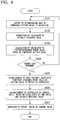
- FIG. 4 shows the operation of the control system 1 of the first embodiment.
- the determiner 410 outputs a temporary setting value to the calculator 400 (step S101).
- the calculator 400 acquires from the device 2 information indicating the actually measured value of the power of the device 2 (step S102).
- the calculator 400 calculates the temporary consumed power value of the device 2, based on the actually measured vale of the power, the temporary setting value and the device model of the device 2 (step S103).
- the determiner 410 determines whether the energy cost of the calculated temporary consumed power value is minimum (step S104). If the energy cost is not minimum (NO at step S104), the determiner 410 returns processing to step S101. If the energy cost is minimum (YES at step S104), the determiner 410 establishes the most recently calculated temporary consumed power value as the setting value to output to the controller 3. The determiner 410 outputs the established setting value to the controller 3 (step S 105).
- the controller 3 establishes the control value, based on the established setting value and the actually measured value of the power of the device 2.
- the controller 3 outputs the control value to the device 2 (step S 106).
- the device 2 operates based on the control value (step S107).
- the difference between the actually measured value of the power of the device 2 and the target value of the power of the device 2 is kept within a prescribed range.
- FIG. 5 shows the operation of the calculator 400 of the first embodiment.
- the calculator 400 acquires the actually measured value y2 of the consumed power (step 201).
- the calculator 400 calculates the value x2 associated with the control value, based on the actually measured value y2 of the consumed power (step S202).
- the calculator 400 acquires the most recent setting value x2 from the determiner 40 (step S203).
- the calculator 400 calculates the value y3 associated with the actually measured value of the consumed power, based on the value x2 associated with the control value (step S204).
- the calculator 400 acquires the temporary setting value x1 from the determiner 410 (step S205).
- the calculator 400 calculates the provisional value y1 of the temporary consumed power (step S206).
- the calculator 400 establishes the value obtained by adding the provisional value y1 of the temporary consumed power of the device 2 and the correction value ⁇ y as the temporary consumed power value of the device 2.
- the calculator 400 outputs information indicating the temporary consumed power value to the determiner 410 (step S207).
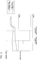
- FIG. 6 shows the change of the consumed power in the first embodiment.
- the horizontal axis of the top graph in FIG. 6 represents time
- the vertical axis represents the consumed power
- the solid line represents the actually measured value of the consumed power of the device 2
- the single dot-dash line represents the target value of the consumed power of the device 2.
- the vertical axis represents the correction value ⁇ y
- the horizontal axis represents time.
- the temporary consumed power value (target value) based on the provisional value y1 of the temporary consumed power of the device 2 and the actually measured value y2 of the consumed power of the device 2 will not coincide.
- the calculator 400 acquires information indicating the temporary consumed power value (target value) based on the provisional value y1 of the temporary consumed power of the device 2 and information indicating the error of the actually measured value y2 of the consumed power of the device 2, either at a prescribed interval or at an arbitrary time.
- the calculator 400 calculates the correction value ⁇ y of the consumed power, based on this acquired information.
- the calculator 400 may calculate the correction value ⁇ y of the consumed power based on the average value of the temporary setting value x1, or based on average value of the actually measured value y2 of the consumed power of the device 2, which case the calculator 400 can suppress variation in the correction value ⁇ y.
- the device operation setting apparatus 40 of the first embodiment has a calculator 400 and a determiner 410.
- the calculator 400 calculates the target value of the consumed power of the device 2 based on the relationship between the setting value regarding operation control of the device 2 and the consumed power of the device 2.
- the determiner 410 determines the setting value so that the difference between the actually measured value of the consumed power of the device 2 and the target value of the consumed power of the device 2, which is calculated by the calculator 400, is within a prescribed range. The same applies to generated power.
- a device operation setting value determination program of the first embodiment causes a computer to execute a procedure that calculates a target value of the consumed power of the device 2, based on the relationship between the setting value regarding operation control of the device 2 and the consumed power of the device 2.
- the device operation setting value determination program of the first embodiment causes a computer to execute a procedure to determine a setting value so that the difference between the actually measured value of the consumed power of the device 2 and the calculated target value of the consumed power of the device 2 is within a prescribed range.
- the calculator 400 calculates the target value of the consumed power of the device 2, based on the relationship between the setting value regarding operation control of the device 2 and the consumed power of the device 2. This enables the device operation setting apparatus 40 and the device operation setting value determination program of the first embodiment to make the difference between the actual measured value of the power of the device 2 and the target value of the power of the device 2 within a prescribed range.
- the provision of an electric generator 2a at the device 2 in the control system 1 is the point of difference with respect to the first embodiment. In the second embodiment, only the point of difference with respect to the first embodiment will be described.
- FIG. 7 shows a control system 1 of the second embodiment.
- the control system 1 has an electric generator 2a as the device 2, a controller 3, and a management system 4.
- the electric generator 2a outputs generated power 11 via the local wiring 6.
- the other consumed power 9 is power that is the sum of the received power 7 and the generated power 11.
- FIG. 8 shows the electric generator 2a of the second embodiment.
- the electric generator 2a has a turbine 20a, a generator 21 a, and a condenser 22a.
- the turbine 20a drives the generator 21 a by steam from a boiler (boiler main steam amount optimized value (GnoBOpt)).
- the generator 21a generates electricity in response to drive by the turbine 20a (turbine generated amount (ENoT)).
- the condenser 22a cools the steam that has flowed from the turbine 20a (turbine condenser cooling water intake temperature (TNoTVin), turbine vacuum level reference value (VNoTV)), changing it to water.
- TNoTVin turbine condenser cooling water intake temperature
- VNoTV turbine vacuum level reference value
- the device model in the second embodiment will be called the generator model
- the temporary consumed power value calculated based on the generator model will be called the current state value
- the optimum setting value determined based on the generator model will be called the optimum value.
- FIG. 9 shows the variable names in the second embodiment.
- the name of the variable representing boiler main steam amount (main steam flow amount) is GNoB.
- the name of the variable representing the generated power of the turbine 20a is ENoT.
- the name of the variable representing the condenser cooling water intake temperature (cooling water) of the turbine 20a is TNoVin.
- the name of the variable representing the modeling constants a0 to a7 of the turbine 20a is aNoT.
- the name of the variable representing the condenser model constants a0 to a7 of the turbine 20a is aNoTV.
- the name of the variable representing the condenser flow amount rating of the turbine 20a is GNoTex0.
- the name of the variable representing the vacuum level reference value of the turbine 20a is VNoTV0.
- the name of the variable representing the turbine 20a condenser upper limit model constants a0 to a4 is cNoTV_h.
- the name of the variable representing the turbine 20a condenser lower limit constants a0 to a4 is cNoTV_1.
- the name of the variable representing the turbine 20a main steam optimized item is flg_NoTOpt.
- the name of the variable representing the boiler main steam amount optimum value is GNoBOpt.
- the name of the variable representing the turbine 20a generated power optimum value is ENoTOpt.
- the name of the variable representing the inflow amount to the condenser 22a is GNoTex.
- the name of the variable representing the optimum value of the inflow amount to the condenser 22a is GnoTexOpt.
- the name of the variable representing the condenser 22a vacuum level optimum value is VNoTVOpt.
- the name of the variable representing the generated power calculated value is EnoTCal.
- the name of the variable representing the generated power optimum calculated value is ENoTOptCal.
- the name of the variable representing the condenser inflow amount corresponding to the condenser 22a vacuum level upper limit is GNoTex_h.
- the name of the variable representing the condenser inflow amount corresponding to the condenser 22a vacuum level lower limit is GNoTex_l.
- the name of the variable representing the generated power is ENoB.
- the name of the variable representing the vacuum level is VNoTV.
- the name of the variable representing the air flow amount optimum value is NoBOpt.
- the name of the variable representing the generated power optimum value is EnoBOpt.
- the inflow amount to the condenser 22a is the same as the main steam amount.
- the calculator 400 substitutes the value of the variable GNoB representing the boiler main steam amount (main steam flow amount) into the variable GNoTex representing the inflow amount to the condenser 22a.
- the calculator 400 substitutes the value of the variable representing the boiler main steam amount optimum value into the variable GnoTexOpt representing the optimum inflow amount value to the condenser 22a.
- the steam consumption characteristics of the turbine 20a are expressed by Equation (5), using the ⁇ (vacuum level) (vacuum level - vacuum level reference value).
- Main steam amount a 0 + a 1 ⁇ Generated power + a 2 ⁇ ⁇ vacuum level
- Equation (5) also applies with respect to either the current state value or the optimum value.
- the main steam amount, the generated power, and the ⁇ (vacuum level) (vacuum level - vacuum level reference value) are all actually measured values, because of the error (generator model error) of the emulation of the operation of the electric generator 2a and the controller 3 and the sensor measurement error, Equation (5) is not satisfied.
- the general power amount is not a target directly manipulated, such as at the operating end. Given this, the variable ENoTCal representing the generated power calculated value and the variable ENoTOptCal representing the calculated generated power optimum value are used in place of the actually measured values. These variables are for satisfying Equation (5).
- Equation (6) The turbine 20a characteristics are expressed by Equation (6) and Equation (7).
- GNoBOpt aNoT 0 + aNoT 1 ⁇ ENoTOptCal + aNoT 2 ⁇ VNoTVOpt ⁇ VNoTV 0
- GNoB NoT 0 + aNoT 1 ⁇ ENoTCal + aNoT 1 ⁇ VNoTV ⁇ VNoTV 0
- the calculator 400 calculates the steam consumption characteristics, based on the variable VNoTVOpt that represents the condenser 22a vacuum level optimum value.
- the calculator 400 calculates the variable VNoTVOpt based on a line that represents the predicted performance.
- FIG. 10 shows lines representing the performance of predicting the vacuum level in a condenser 22a in the second embodiment.
- the vertical axis represents the vacuum level (%) and the horizontal axis represents the amount of heat exchange (mmHg).
- the value of the vacuum level may be approximated by a straight line, or by a curved line.
- Equation (9) shows one example of the approximate vacuum level value, in which av0 is an arbitrary constant.
- Vaccum level av 0 + av 1 ⁇ cooling water intake temperature + av 2 ⁇ amount of heat exchange + av 3 ⁇ cooling water intake temperature ⁇ cooling water intake temperature + av 4 ⁇ cooling water intake temperature ⁇ amount of heat exchange
- the condenser 22a is highly dependent upon the outside air temperature. For that reason, the assumption is made that the cooling water intake temperature does not vary near the point at which the operating point reaches the optimum point. Equation (9) is satisfied even after reaching the optimum point.
- Vaccum level optimum value av 0 + av 1 ⁇ cooling water intake temperature + av 2 ⁇ amount of heat exchange optimum value + av 3 ⁇ cooling water intake temperature ⁇ cooling water intake temperature + av 4 ⁇ cooling water intake temperature ⁇ amount of heat exchange optimum value
- Vacuum level optimum value ⁇ vacuum level av 2 + av 4 ⁇ cooling water intake temperature ⁇ amount of heat exchange optimum value
- Equation (11) is a calculated value based on design data. For that reason, there is an error between the calculated value indicated by Equation (11) and the actually measured vacuum level value. To correct this error, the calculator 400 assumes that the amount of heat exchange is proportional to the condenser inflow amount with respect to the heat exchange amount rating, and calculates the variable VNoTVOpt indicating the optimum vacuum level value of the condenser 22a. That is, the calculator 400 assumes that change in the vacuum level in the design data is the same as the change in the vacuum level at the actual operating point, and determines whether Equation (12) is satisfied.
- VNoTVOpt VNoTV + aNoTV 2 + aNoTV 5 ⁇ TNoTVin ⁇ GNoTexOpt ⁇ GNoTex / GNoTex 0
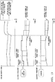
- FIG. 11 shows the variation of the amount of power generated by the electric generator 2a in the second embodiment.
- the vertical axis represents the main steam amount (kg/s) to the turbine 20a.
- the vertical axis represents the electric power (kW).
- the vertical axis represents the electric power (kW).
- the horizontal axes in the upper, middle, and lower graphs represent time.
- the received power amount will be called the received power
- the target value of the received power will be called the received power target value.
- the upper graph of FIG. 11 shows the main steam amount for the case in which the consumed power is corrected and the main steam amount for the case in which the consumed power is not corrected. There is a difference between the main steam amount for the case in which the calculator 400 corrects the consumed power and the case in which it does not correct the consumed power. If the consumed power is not corrected, as seen in the middle graph in FIG. 11 , the received power 7, which is the other consumed power 9 minus the generated power, and received power target value do not coincide, because of the error in the generator model.
- the consumed power is not corrected, as shown in the lower graph in FIG. 11 , the received power 7, which is the other consumed power 9 minus the generated power, and received power target value (temporary consumed power value) coincide.
- the degree of coincidence is dependent on the error of the generator model.
- the calculator 400 calculates the consumed power correction value, based on the actually measured generated power, the setting value (main steam amount setting value), and the generator model.
- the determiner 410 causes the received power 7 and the received power target value to coincide.
- the device operation setting apparatus 40 of the second embodiment has a calculator 400 and a determiner 410.
- the calculator 400 calculates the consumed power target value of the electric generator 2a, based on the relationship (generator model) between the setting value regarding operation control of the electric generator 2a and the consumed power of the electric generator 2a.
- the determiner 410 determines the setting value so that the difference between the actually measured value of the consumed power of the electric generator 2a and the consumed power target value of the electric generator 2a calculated by the calculator 400 is within a prescribed range.
- the device operation setting value determination program of the second embodiment causes a computer to execute a procedure to calculate the consumed power target value of the electric generator 2a, based on the relationship (generator model) between the setting value regarding operation control of the electric generator 2a and the consumed power of the electric generator 2a.
- the device operation setting value determination program of the second embodiment also causes a computer to execute a procedure to determine a setting value so that the difference between the actually measured value of the consumed power of the electric generator 2a and the consumed power target value of the electric generator 2a calculated by the calculator 400 is within a prescribed range.
- the calculator 400 calculates the consumed power target value of the electric generator 2a, based on the relationship between the setting value regarding operation control of the electric generator 2a and the consumed power of the electric generator 2a. This enables the device operation setting apparatus 40 and the device operation setting value determination program of the second embodiment to make the difference between the actually measured value of the generated power of the electric generator 2a and the generated power target value of the electric generator 2a be within a prescribed range.
- the provision of an electric freezer 2b as the device 2 in the control system 1 is the point of difference with respect to the first embodiment and the second embodiment. In the third embodiment, only the point of difference with respect to the first embodiment and the second embodiment will be described.
- FIG. 12 shows the control system 1 of the third embodiment.
- the control system 1 has an electric freezer 2b as the device 2, a controller 3, and a management system 4.
- the controller 3 controls the opening of a valve 13 in response to a control value for the valve 13.
- the controller 3 controls the opening of a valve 14 in response to a control value for the valve 14.
- cooling heat may be understood to be warming heat.
- a heat storage tank 12 outputs cooling/waming heat to the cooling/warming load, via the valve 13.
- the valve 13 To simplify the description, in the following the assumption will be made that a sufficient amount of cooling/warming heat is stored in the heat storage tank 12. Even if this assumption is made, generality is not lost. This is because the heat storage tank 12 may store a sufficient amount of cooling/warming heat beforehand, by the electric freezer 2b or the like.
- the electric freezer 2b acquires consumed power 8 via local wiring 6.
- the electric freezer 2b outputs cooling water to the cooling/warming load, via the valve 14.
- the cooling water output by the electric freezer 2b and the cooling/warming heat output by the heat storage tank 12 merge, becoming the cooling/warming heat 15.
- the cooling/warming heat 15 is supplied to the cooling/warming heat load.
- the device model in the third embodiment will be called the electric freezer model.
- the determiner 410 adjusts the received power 7 so that the received power 7 and the received power target value are made to coincide.
- the determiner 410 adjusts the consumed power 8 of the electric freezer 2b to enable adjustment of the received power 7.
- the consumed power 8 of the electric freezer 2b is not something that can be directly manipulated at an operating end, such as the valve 13 or the valve 14.
- the consumed power 8 of the electric freezer 2b differs, depending upon the load (hereinafter "cooling water load") of the cooling water. For that reason, the determiner 410 appropriately controls the operating end, such as the valve 13 or the valve 14, so as to control the consumed power 8 of the electric freezer 2b.
- the calculator 400 calculates the consumed power correction value, based on the actually measured value of the consumed power, the setting value, and the electric freezer model. By doing this, the determiner 410 causes the received power 7 and the received power target value to coincide. Because of the error of the electric freezer model, the consumed power 8 of the electric freezer 2b calculated using the electric freezer model and the actually measured value of the consumed power 8 of the electric freezer 2b do not coincide.
- the calculator 400 calculates the correction value of the consumed power, based on the actually measured value of the consumed power, the setting value (cooling water load), and the electric freezer model. By doing this, the determiner 410 causes the received power 7 and the received power target value to coincide.
- FIG. 13 shows the variation of the consumed power of the electric freezer 2b in the third embodiment.
- the vertical axis represents the cooling water load of the electric freezer 2b.
- the vertical axis represents the power (kW).
- the horizontal axes in the upper, middle, and lower graphs represent time.
- the upper graph of FIG. 13 shows the cooling water load for the case in which the consumed power is corrected and the cooling water load for the case in which the consumed power is not corrected. There is a difference between the cooling water load for the case in which the calculator 400 corrects the consumed power and the cooling water load for the case in which the consumed power is not corrected. If the consumed power is not corrected, as shown in the middle graph of FIG. 13 , because of the error of the electric freezer model, the received power, which is the sum of the other consumed power 9 and the consumed power 8, and the received power target value do not coincide.
- the received power 7 which is the sum of the other consumed power 9 and the consumed power 8 and the received power target value (temporary consumed power value) coincide.
- the degree of coincidence is dependent on the error of the electric freezer model.
- the calculator 400 calculates the consumed power correction value, based on the actually measured consumed power, the setting value (cooling water load), and the electric freezer model. By doing this the determiner 410 causes the received power 7 and the received power target value to coincide.
- the determiner 410 may determine whether, by changing the setting value, the difference between actually measured power of the electric freezer 2b and the target value can be made to be within a prescribed range. If the cooling/warming heat 15 supplied to the cooling/warming load is insufficient, the heat storage tank 12 may increase the amount of cooling/warming heat output to the cooling/warming load. In this case, the controller 3 adjusts the opening of the valve 13, based on a control value responsive to the setting value.
- the device operation setting apparatus 40 of the third embodiment has a calculator 400 and a determiner 410.
- the calculator 400 calculates the consumed power target value of the electric freezer 2b, based on the relationship (electric freezer model) between the setting value regarding operation control of the electric freezer 2b and the consumed power of the electric freezer 2b.
- the determiner 410 determines the setting value so that the difference between the actually measured consumed power of the electric freezer 2b and the consumed power target value of the electric freezer 2b calculated by the calculator 400 is within a prescribed range.
- the device operation setting value determination program of the third embodiment causes a computer to execute a procedure to calculate the consumed power target value of the electric freezer 2b, based on the relationship (electric freezer model) between the setting value regarding operation control of the electric freezer 2b and the consumed power of the electric freezer 2b.
- the device operation setting value determination program of the third embodiment also causes a computer to execute a procedure to determine a setting value so that the difference between the actually measured consumed power of the electric freezer 2b and the consumed power target value of the electric freezer 2b calculated by the calculator 400 is within a prescribed range.
- the calculator 400 calculates the consumed power target value of the electric freezer 2b, based on the relationship between the setting value regarding operation control of the electric freezer 2b and the consumed power of the electric freezer 2b. This enables the device operation setting apparatus 40 and the device operation setting value determination program of the third embodiment to make the difference between the actually measured value of cooling/warming heat of the electric freezer 2b and the cooling/warming heat target value of the electric freezer 2b be within a prescribed range.
- the determiner 410 determines whether or not, by changing the setting value, it is possible to make the difference between the actually measured value of power of the electric freezer 2b and the calculated target value be within a prescribed range. If it is not possible to make the difference between the actually measured value of the electric freezer 2b and the calculated target value be within the prescribed range, the determiner 410 controls the heat storage tank 12 or the valve 13, via the controller 3, so that the difference is made to be within the prescribed range.
- the device operation setting value determination program may be recorded in a computer-readable storage medium.
- the computer-readable storage medium is, for example, a removable medium, such as a flexible disk, an opto-magnetic disk, a ROM, a CD-ROM, or a flash memory, or a storage device such as a hard disk built into a computer system.
- the device operation setting value determination program may be transmitted via an electrical communication circuit.
- a calculator calculates a target value of the consumed power of a device based on the relationship between a setting value regarding operation control of the device and the consumed power of the device, the difference between the actually measured value of consumed power of the device and the power target value of the device can be made to be within a prescribed range.
Landscapes
- Engineering & Computer Science (AREA)
- Mechanical Engineering (AREA)
- General Engineering & Computer Science (AREA)
- Chemical & Material Sciences (AREA)
- Combustion & Propulsion (AREA)
- Physics & Mathematics (AREA)
- Power Engineering (AREA)
- Signal Processing (AREA)
- General Physics & Mathematics (AREA)
- Automation & Control Theory (AREA)
- Mathematical Physics (AREA)
- Fuzzy Systems (AREA)
- Electromagnetism (AREA)
- Radar, Positioning & Navigation (AREA)
- Supply And Distribution Of Alternating Current (AREA)
- Feedback Control In General (AREA)
- Air Conditioning Control Device (AREA)
- Management, Administration, Business Operations System, And Electronic Commerce (AREA)
Abstract
Description
- Embodiments of the present invention relate to a device operation setting apparatus and a device operation setting value determination program.
- Heat-source devices receive electrical power and generate heat. Power-source devices receive electrical power and generate electricity. Energy consumed by heat-source devices and power-source devices account for a large part of energy consumed in factories and office buildings. A device operation setting apparatus may establish the details of device operation so as to optimize the device operation. When the device operation setting apparatus receives a demand response (DR) signal, it determines a setting value regarding operation of a device, so that the actually measured value of consumed power of a device coincides with a target value. The device operation setting apparatus operates a device in response to the determined setting value. However, there are cases in which, because of device deterioration or environmental condition, the device operation setting apparatus cannot make the difference between the actually measured consumed power value of a device and the target value of the consumed power of the device in accordance with a determined setting value to be within a prescribed range.
- [Patent Reference 1]: Japanese Patent No.
4396557 - The problem the present invention seeks to solve is that of providing a device operation setting apparatus and a device operation setting value determination program capable of making the difference between the actually measured consumed power value of a device and the target value of the consumed power of the device to be within a prescribed range.
- A device operation setting apparatus of an embodiment has a calculator and a determiner. The calculator, based on the relationship between a setting value regarding operation control of a device and the consumed power of the device, calculates a target value of the consumed power of the device. The determiner determines the setting value so that the difference between the actually measured consumed power of the measured device and the target value of the consumed power of the device calculated by the calculator is within a prescribed range.
-
-
FIG. 1 shows a control system within a building in a first embodiment. -
FIG. 2 shows a control system of the first embodiment. -
FIG. 3 shows the hardware of a control system of the first embodiment. -
FIG. 4 shows the operation of a control system of the first embodiment. -
FIG. 5 shows the operation of the calculator of the first embodiment. -
FIG. 6 shows the change of the consumed power in the first embodiment. -
FIG. 7 shows a control system of a second embodiment. -
FIG. 8 shows an electric generator in the second embodiment. -
FIG. 9 shows the variable names in the second embodiment. -
FIG. 10 shows lines representing the performance of predicting the vacuum level in a condenser in the second embodiment. -
FIG. 11 shows the variation of the amount of electrical generation of an electric generator in the second embodiment. -
FIG. 12 shows a control system in a third embodiment. -
FIG. 13 shows the variation of the amount of consumed power in an electric freezer in the third embodiment. - Embodiments of a device operation setting apparatus and a device operation setting value determination program will be described below, with references made to the drawings.
-
FIG. 1 shows the constitution of acontrol system 1 of the first embodiment. Thecontrol system 1 has adevice 2, acontroller 3, a management system 4 (a building/energy monitoring control apparatus). Thecontrol system 1 may have a plurality ofdevices 2. Thecontrol system 1 may have a plurality ofcontrollers 3. Thecontrol system 1 may be provided in a building A or in another prescribed location other than the building A. In thiscontrol system 1, these functional blocks may be distributed and provided in a prescribed range. - Next, an example of the constitution of the
control system 1 will be described. -
FIG. 2 shows the control system in the first embodiment.FIG. 3 shows the hardware of the control system of the first embodiment. - The
transformer 5 is connected to thelocal wiring 6. Thetransformer 5 outputs a received electric power 7 (secondary side power) to thelocal wiring 6. Thelocal wiring 6 supplies the consumedpower 8 to thedevice 2. - The
device 2 acquires the consumedpower 8 via thelocal wiring 6. The other consumedpower 9 is the power remaining when the consumedpower 8 is subtracted from the receivedpower 7. The other consumedpower 9 is consumed by other power loads (not shown). Thedevice 2 acquires a control value from thecontroller 3. Thedevice 2 executes a prescribed operation based on the control value. Thedevice 2 outputs information indicating the consumedpower 8 of thedevice 2 or the actually measured value of generated power (sensor value) to thecontroller 3 and the deviceoperation setting apparatus 40, via thecommunication circuit 10. Thecommunication circuit 10 is, for example, a communication circuit within an office building. Thedevice 2 is, for example, a power-sourcing device or an energy-sourcing device, and may be an office-automation device. - The
controller 3 acquires a setting value from themanagement system 4, via thecommunication circuit 10. Thecontroller 3 determines a control value based on the setting value. Thecontroller 3 outputs the control value to thedevice 2. - The
management system 4 determines the setting value based on information acquired from outside. By outputting the setting value to thecontroller 3, themanagement system 4 controls the consumedpower 8, the generated power, and the amount of heat of thedevice 2. Themanagement system 4, based on a demand response signal (DR signal), controls the consumedpower 8, the generated power, and the amount of heat of thedevice 2. The demand response signal DR includes, for example, command information that controls the power or information indicating the power peak shift target. Themanagement system 4 may, based on a weather forecast signal, control the consumedpower 8, the generated power, and the amount of heat of thedevice 2. - The
management system 4 has acalculator 400 and adeterminer 410. A part or all of thecalculator 400 and thedeterminer 410 is a software functional unit that functions by a processor such as a CPU (central processing unit) executing a program stored in memory. A part or all of these may be a hardware functional unit such as an LSI (large-scale integration) device or an ASIC (application-specific integrated circuit). - The
calculator 400 has a volatile memory such as a RAM (random-access memory) or a register. Thecalculator 400 may have a non-volatile memory (non-temporary recording medium) such as a ROM (read-only memory), a flash memory, or a hard-disk drive. The non-volatile memory stores a program for the purpose of operating a processor such as a CPU. - The non-volatile memory stores information representing a model (hereinafter called the device model) that emulates the operation of the
device 2 and thecontroller 3. The device model represents the relationship between the target value of the power of thedevice 2, which operates in accordance with the setting value, and that setting value. The device model may be expressed as a characteristics equation indicating the power and heat characteristics of thedevice 2, or may be expressed as a table of correspondence that establishes a correspondence between power or heat target value and the setting value of thedevice 2. The deterioration of thedevice 2 and thecontroller 3 or the environmental conditions may be reflected in the device model. - The
calculator 400 acquires from thedevice 2 information indicating thedevice 2 consumedpower 8 or generated power actual measured value (sensor value). Thecalculator 400 acquires from the determiner 410 a setting value acquired by thecontroller 3 from thedeterminer 410. Thecalculator 400 acquires a temporary setting value from thedeterminer 410. The temporary setting value is a setting value used by thecalculator 400 to calculate the target value, based on the device model. Thecalculator 400 calculates the consumed power value (hereinafter called the temporary consumed power value) of thedevice 2 for the case of operation in accordance with the temporary setting value, based on the device model. Thecalculator 400 outputs information indicating the temporary consumed power value to thedeterminer 410. - The characteristics equation of the device model may be any type of equation. An example of a first characteristics equation representing the device model is represented by Equation (1).

- In the above, x1 is the temporary setting value, y1 is the provisional value of the temporary consumed power of the
device 2, and a and b are constants. - An example of a second characteristics equation representing the device model is represented by Equation (2).

- In the above, x2 is a value associated with the control value, y2 is an actually measured value of the consumed power of the
device 2, and a and b are constants. - An example of a third characteristics equation representing the device model is represented by Equation (3).

- In the above, x3 is a setting value, y3 is a value associated with the actually measured value of the consumed power of the
device 2, and a and b are constants. - As described above, the device model emulates the operation of the
device 2 and thecontroller 3. - If there is no error in the emulation of the operation of the
device 2 and thecontroller 3, the actually measured value y2 of the consumed power of thedevice 2 and the value y3 associated with the actually measured value of consumed power ofdevice 2 coincide. In this case, the value x2 associated with the control value and the setting value x3 coincide. - If there is an error in the emulation of the operation of the
device 2 and thecontroller 3, even if thedeterminer 410 outputs the temporary setting value x1 indicated by Equation (1) to thecontroller 3, the actually measured value of the consumed power of thedevice 2 and the provisional value y1 of the temporary consumed power of thedevice 2 will not coincide. - Given this, the
calculator 400 performs correction so as to make the error between the temporary consumed power value based on the provisional value y1 of the temporary consumed power and the actually measured value y2 of the consumed power small. For example, thecalculator 400, by adding a correction value Δy to the provisional value y1 of the temporary consumed power of thedevice 2, corrects the error with respect to the actually measured value y2 of the consumed power of thedevice 2. Thecalculator 400 may, by subtracting the correction value Δy from the provisional value y1 of the temporary consumed power of thedevice 2 or multiplying or dividing the provisional value y1 of the temporary consumed power of the device by the correction value Δy, correct the error with respect to the actually measured value y2 of the consumed power of thedevice 2. The correction value Δy is represented by Equation (4).
- The
calculator 400 establishes the value obtained by adding the provisional value y1 of the temporary consumed power of thedevice 2 and the correction value Δy as the temporary consumed power value of thedevice 2. Thecalculator 400 outputs information indicating the temporary consumed power value to thedeterminer 410. - The
determiner 410 acquires information indicating the temporary consumed power value from thecalculator 400. Thedeterminer 410 calculates the optimal setting value, based on the temporary consumed power value. The optimal setting value is, for example, is the setting value for which the energy cost is minimum. Thedeterminer 410 may calculate the optimal setting value by any method, and there is no restriction to any particular calculation method. For example, thedeterminer 410 establishes the setting value so that the setting value is within a first range (upper and lower limits). For example, thedeterminer 410 establishes the setting value so that the temporary consumed power value (target value) is within a second range (upper and lower limits). Thedeterminer 410 outputs the optimal setting value to thecalculator 400 and thecontroller 3. Thedeterminer 410 may calculate the optimal setting value as a prescribed period. The prescribed period may be, for example, a period of 24 hours, or a period of 10 minutes. -
FIG. 4 shows the operation of thecontrol system 1 of the first embodiment. - The
determiner 410 outputs a temporary setting value to the calculator 400 (step S101). - The
calculator 400 acquires from thedevice 2 information indicating the actually measured value of the power of the device 2 (step S102). - The
calculator 400 calculates the temporary consumed power value of thedevice 2, based on the actually measured vale of the power, the temporary setting value and the device model of the device 2 (step S103). - The
determiner 410 determines whether the energy cost of the calculated temporary consumed power value is minimum (step S104). If the energy cost is not minimum (NO at step S104), thedeterminer 410 returns processing to step S101. If the energy cost is minimum (YES at step S104), thedeterminer 410 establishes the most recently calculated temporary consumed power value as the setting value to output to thecontroller 3. Thedeterminer 410 outputs the established setting value to the controller 3 (step S 105). - The
controller 3 establishes the control value, based on the established setting value and the actually measured value of the power of thedevice 2. Thecontroller 3 outputs the control value to the device 2 (step S 106). - The
device 2 operates based on the control value (step S107). The difference between the actually measured value of the power of thedevice 2 and the target value of the power of thedevice 2 is kept within a prescribed range. -
FIG. 5 shows the operation of thecalculator 400 of the first embodiment. - The
calculator 400 acquires the actually measured value y2 of the consumed power (step 201). - The
calculator 400, calculates the value x2 associated with the control value, based on the actually measured value y2 of the consumed power (step S202). - The
calculator 400 acquires the most recent setting value x2 from the determiner 40 (step S203). - The
calculator 400 calculates the value y3 associated with the actually measured value of the consumed power, based on the value x2 associated with the control value (step S204). - The
calculator 400 acquires the temporary setting value x1 from the determiner 410 (step S205). - The
calculator 400 calculates the provisional value y1 of the temporary consumed power (step S206). - The
calculator 400 establishes the value obtained by adding the provisional value y1 of the temporary consumed power of thedevice 2 and the correction value Δy as the temporary consumed power value of thedevice 2. Thecalculator 400 outputs information indicating the temporary consumed power value to the determiner 410 (step S207). -
FIG. 6 shows the change of the consumed power in the first embodiment. The horizontal axis of the top graph inFIG. 6 represents time, the vertical axis represents the consumed power, the solid line represents the actually measured value of the consumed power of thedevice 2, and the single dot-dash line represents the target value of the consumed power of thedevice 2. In the bottom graph inFIG. 6 , the vertical axis represents the correction value Δy, and the horizontal axis represents time. - If there is an error between the device model and the operation of the
device 2, the temporary consumed power value (target value) based on the provisional value y1 of the temporary consumed power of thedevice 2 and the actually measured value y2 of the consumed power of thedevice 2 will not coincide. - The
calculator 400 acquires information indicating the temporary consumed power value (target value) based on the provisional value y1 of the temporary consumed power of thedevice 2 and information indicating the error of the actually measured value y2 of the consumed power of thedevice 2, either at a prescribed interval or at an arbitrary time. Thecalculator 400 calculates the correction value Δy of the consumed power, based on this acquired information. - The
calculator 400 may calculate the correction value Δy of the consumed power based on the average value of the temporary setting value x1, or based on average value of the actually measured value y2 of the consumed power of thedevice 2, which case thecalculator 400 can suppress variation in the correction value Δy. - In this manner, the device
operation setting apparatus 40 of the first embodiment has acalculator 400 and adeterminer 410. Thecalculator 400 calculates the target value of the consumed power of thedevice 2 based on the relationship between the setting value regarding operation control of thedevice 2 and the consumed power of thedevice 2. Thedeterminer 410 determines the setting value so that the difference between the actually measured value of the consumed power of thedevice 2 and the target value of the consumed power of thedevice 2, which is calculated by thecalculator 400, is within a prescribed range. The same applies to generated power. - A device operation setting value determination program of the first embodiment causes a computer to execute a procedure that calculates a target value of the consumed power of the
device 2, based on the relationship between the setting value regarding operation control of thedevice 2 and the consumed power of thedevice 2. The device operation setting value determination program of the first embodiment causes a computer to execute a procedure to determine a setting value so that the difference between the actually measured value of the consumed power of thedevice 2 and the calculated target value of the consumed power of thedevice 2 is within a prescribed range. - By this constitution, the
calculator 400 calculates the target value of the consumed power of thedevice 2, based on the relationship between the setting value regarding operation control of thedevice 2 and the consumed power of thedevice 2. This enables the deviceoperation setting apparatus 40 and the device operation setting value determination program of the first embodiment to make the difference between the actual measured value of the power of thedevice 2 and the target value of the power of thedevice 2 within a prescribed range. - In the second embodiment, the provision of an
electric generator 2a at thedevice 2 in thecontrol system 1 is the point of difference with respect to the first embodiment. In the second embodiment, only the point of difference with respect to the first embodiment will be described. -
FIG. 7 shows acontrol system 1 of the second embodiment. Thecontrol system 1 has anelectric generator 2a as thedevice 2, acontroller 3, and amanagement system 4. Theelectric generator 2a outputs generatedpower 11 via thelocal wiring 6. The other consumedpower 9 is power that is the sum of the receivedpower 7 and the generatedpower 11. -
FIG. 8 shows theelectric generator 2a of the second embodiment. Theelectric generator 2a has aturbine 20a, agenerator 21 a, and acondenser 22a. Theturbine 20a drives thegenerator 21 a by steam from a boiler (boiler main steam amount optimized value (GnoBOpt)). Thegenerator 21a generates electricity in response to drive by theturbine 20a (turbine generated amount (ENoT)). Thecondenser 22a cools the steam that has flowed from theturbine 20a (turbine condenser cooling water intake temperature (TNoTVin), turbine vacuum level reference value (VNoTV)), changing it to water. - In the following, the device model in the second embodiment will be called the generator model, the temporary consumed power value calculated based on the generator model will be called the current state value, and the optimum setting value determined based on the generator model will be called the optimum value.
-
FIG. 9 shows the variable names in the second embodiment. The name of the variable representing boiler main steam amount (main steam flow amount) is GNoB. The name of the variable representing the generated power of theturbine 20a is ENoT. The name of the variable representing the condenser cooling water intake temperature (cooling water) of theturbine 20a is TNoVin. The name of the variable representing the modeling constants a0 to a7 of theturbine 20a is aNoT. The name of the variable representing the condenser model constants a0 to a7 of theturbine 20a is aNoTV. - The name of the variable representing the condenser flow amount rating of the
turbine 20a is GNoTex0. The name of the variable representing the vacuum level reference value of theturbine 20a is VNoTV0. - The name of the variable representing the
turbine 20a condenser upper limit model constants a0 to a4 is cNoTV_h. The name of the variable representing theturbine 20a condenser lower limit constants a0 to a4 is cNoTV_1. The name of the variable representing theturbine 20a main steam optimized item is flg_NoTOpt. The name of the variable representing the boiler main steam amount optimum value is GNoBOpt. The name of the variable representing theturbine 20a generated power optimum value is ENoTOpt. - The name of the variable representing the inflow amount to the
condenser 22a is GNoTex. The name of the variable representing the optimum value of the inflow amount to thecondenser 22a is GnoTexOpt. The name of the variable representing thecondenser 22a vacuum level optimum value is VNoTVOpt. The name of the variable representing the generated power calculated value is EnoTCal. The name of the variable representing the generated power optimum calculated value is ENoTOptCal. The name of the variable representing the condenser inflow amount corresponding to thecondenser 22a vacuum level upper limit is GNoTex_h. The name of the variable representing the condenser inflow amount corresponding to thecondenser 22a vacuum level lower limit is GNoTex_l. - The name of the variable representing the generated power is ENoB. The name of the variable representing the vacuum level is VNoTV. The name of the variable representing the air flow amount optimum value is NoBOpt. The name of the variable representing the generated power optimum value is EnoBOpt.
- The inflow amount to the
condenser 22a is the same as the main steam amount. Thecalculator 400 substitutes the value of the variable GNoB representing the boiler main steam amount (main steam flow amount) into the variable GNoTex representing the inflow amount to thecondenser 22a. Thecalculator 400 substitutes the value of the variable representing the boiler main steam amount optimum value into the variable GnoTexOpt representing the optimum inflow amount value to thecondenser 22a. The steam consumption characteristics of theturbine 20a are expressed by Equation (5), using the Δ(vacuum level) (vacuum level - vacuum level reference value).
- Equation (5) also applies with respect to either the current state value or the optimum value. However, when the main steam amount, the generated power, and the Δ(vacuum level) (vacuum level - vacuum level reference value) are all actually measured values, because of the error (generator model error) of the emulation of the operation of the
electric generator 2a and thecontroller 3 and the sensor measurement error, Equation (5) is not satisfied. The general power amount is not a target directly manipulated, such as at the operating end. Given this, the variable ENoTCal representing the generated power calculated value and the variable ENoTOptCal representing the calculated generated power optimum value are used in place of the actually measured values. These variables are for satisfying Equation (5). Theturbine 20a characteristics are expressed by Equation (6) and Equation (7).

- If the deviation between the variable ENoTCal representing the generated power calculated value and the power generated optimum calculated value variable ENoTOptCal is the same as the actual deviation in generated power, the power generated optimum value variable ENoTOpt is expressed by Equation (8).

- The
calculator 400 calculates the steam consumption characteristics, based on the variable VNoTVOpt that represents thecondenser 22a vacuum level optimum value. Thecalculator 400 calculates the variable VNoTVOpt based on a line that represents the predicted performance. -
FIG. 10 shows lines representing the performance of predicting the vacuum level in acondenser 22a in the second embodiment. The vertical axis represents the vacuum level (%) and the horizontal axis represents the amount of heat exchange (mmHg). The value of the vacuum level may be approximated by a straight line, or by a curved line. Equation (9) shows one example of the approximate vacuum level value, in which av0 is an arbitrary constant.
- The
condenser 22a is highly dependent upon the outside air temperature. For that reason, the assumption is made that the cooling water intake temperature does not vary near the point at which the operating point reaches the optimum point. Equation (9) is satisfied even after reaching the optimum point.
- From Equations (9) and (10), Equation (11) is satisfied.

- Equation (11) is a calculated value based on design data. For that reason, there is an error between the calculated value indicated by Equation (11) and the actually measured vacuum level value. To correct this error, the
calculator 400 assumes that the amount of heat exchange is proportional to the condenser inflow amount with respect to the heat exchange amount rating, and calculates the variable VNoTVOpt indicating the optimum vacuum level value of thecondenser 22a. That is, thecalculator 400 assumes that change in the vacuum level in the design data is the same as the change in the vacuum level at the actual operating point, and determines whether Equation (12) is satisfied.
- When a value is subject to optimization, an upper limit value and a lower limit value is established. If the associated operating end is subjected to optimization, an upper limit value of GNoB_l and a lower limit value of GNoB_h are established for the reheat steam amount optimum value GNoBrhOpt. The same applies to the generated power optimum value EnoTOpt and the condenser inflow amount optimum value GNoTexOpt. In Equation (13), the operator <= indicates the equality comparison operator "less than or equal to."

-
FIG. 11 shows the variation of the amount of power generated by theelectric generator 2a in the second embodiment. In the upper graph, the vertical axis represents the main steam amount (kg/s) to theturbine 20a. In the middle graph, the vertical axis represents the electric power (kW). In the lower graph, the vertical axis represents the electric power (kW). The horizontal axes in the upper, middle, and lower graphs represent time. In the following, the received power amount will be called the received power, and the target value of the received power will be called the received power target value. - The upper graph of
FIG. 11 shows the main steam amount for the case in which the consumed power is corrected and the main steam amount for the case in which the consumed power is not corrected. There is a difference between the main steam amount for the case in which thecalculator 400 corrects the consumed power and the case in which it does not correct the consumed power. If the consumed power is not corrected, as seen in the middle graph inFIG. 11 , the receivedpower 7, which is the other consumedpower 9 minus the generated power, and received power target value do not coincide, because of the error in the generator model. - If the consumed power is not corrected, as shown in the lower graph in
FIG. 11 , the receivedpower 7, which is the other consumedpower 9 minus the generated power, and received power target value (temporary consumed power value) coincide. - The degree of coincidence is dependent on the error of the generator model. The
calculator 400 calculates the consumed power correction value, based on the actually measured generated power, the setting value (main steam amount setting value), and the generator model. - By doing this, the
determiner 410 causes the receivedpower 7 and the received power target value to coincide. - As noted above, the device
operation setting apparatus 40 of the second embodiment has acalculator 400 and adeterminer 410. Thecalculator 400 calculates the consumed power target value of theelectric generator 2a, based on the relationship (generator model) between the setting value regarding operation control of theelectric generator 2a and the consumed power of theelectric generator 2a. Thedeterminer 410 determines the setting value so that the difference between the actually measured value of the consumed power of theelectric generator 2a and the consumed power target value of theelectric generator 2a calculated by thecalculator 400 is within a prescribed range. - The device operation setting value determination program of the second embodiment causes a computer to execute a procedure to calculate the consumed power target value of the
electric generator 2a, based on the relationship (generator model) between the setting value regarding operation control of theelectric generator 2a and the consumed power of theelectric generator 2a. The device operation setting value determination program of the second embodiment also causes a computer to execute a procedure to determine a setting value so that the difference between the actually measured value of the consumed power of theelectric generator 2a and the consumed power target value of theelectric generator 2a calculated by thecalculator 400 is within a prescribed range. - By this constitution, the
calculator 400 calculates the consumed power target value of theelectric generator 2a, based on the relationship between the setting value regarding operation control of theelectric generator 2a and the consumed power of theelectric generator 2a. This enables the deviceoperation setting apparatus 40 and the device operation setting value determination program of the second embodiment to make the difference between the actually measured value of the generated power of theelectric generator 2a and the generated power target value of theelectric generator 2a be within a prescribed range. - In the third embodiment, the provision of an
electric freezer 2b as thedevice 2 in thecontrol system 1 is the point of difference with respect to the first embodiment and the second embodiment. In the third embodiment, only the point of difference with respect to the first embodiment and the second embodiment will be described. -
FIG. 12 shows thecontrol system 1 of the third embodiment. Thecontrol system 1 has anelectric freezer 2b as thedevice 2, acontroller 3, and amanagement system 4. Thecontroller 3 controls the opening of avalve 13 in response to a control value for thevalve 13. Thecontroller 3 controls the opening of avalve 14 in response to a control value for thevalve 14. In the following the term "cooling heat" may be understood to be warming heat. - A
heat storage tank 12 outputs cooling/waming heat to the cooling/warming load, via thevalve 13. To simplify the description, in the following the assumption will be made that a sufficient amount of cooling/warming heat is stored in theheat storage tank 12. Even if this assumption is made, generality is not lost. This is because theheat storage tank 12 may store a sufficient amount of cooling/warming heat beforehand, by theelectric freezer 2b or the like. - The
electric freezer 2b acquires consumedpower 8 vialocal wiring 6. Theelectric freezer 2b outputs cooling water to the cooling/warming load, via thevalve 14. The cooling water output by theelectric freezer 2b and the cooling/warming heat output by theheat storage tank 12 merge, becoming the cooling/warming heat 15. The cooling/warming heat 15 is supplied to the cooling/warming heat load. In the following, the device model in the third embodiment will be called the electric freezer model. - If the other consumed
power 9 is fixed, thedeterminer 410 adjusts the receivedpower 7 so that the receivedpower 7 and the received power target value are made to coincide. Thedeterminer 410 adjusts the consumedpower 8 of theelectric freezer 2b to enable adjustment of the receivedpower 7. The consumedpower 8 of theelectric freezer 2b is not something that can be directly manipulated at an operating end, such as thevalve 13 or thevalve 14. The consumedpower 8 of theelectric freezer 2b differs, depending upon the load (hereinafter "cooling water load") of the cooling water. For that reason, thedeterminer 410 appropriately controls the operating end, such as thevalve 13 or thevalve 14, so as to control the consumedpower 8 of theelectric freezer 2b. - The
calculator 400 calculates the consumed power correction value, based on the actually measured value of the consumed power, the setting value, and the electric freezer model. By doing this, thedeterminer 410 causes the receivedpower 7 and the received power target value to coincide. Because of the error of the electric freezer model, the consumedpower 8 of theelectric freezer 2b calculated using the electric freezer model and the actually measured value of the consumedpower 8 of theelectric freezer 2b do not coincide. Thecalculator 400 calculates the correction value of the consumed power, based on the actually measured value of the consumed power, the setting value (cooling water load), and the electric freezer model. By doing this, thedeterminer 410 causes the receivedpower 7 and the received power target value to coincide. -
FIG. 13 shows the variation of the consumed power of theelectric freezer 2b in the third embodiment. In the upper graph, the vertical axis represents the cooling water load of theelectric freezer 2b. In the middle and lower graphs, the vertical axis represents the power (kW). The horizontal axes in the upper, middle, and lower graphs represent time. - The upper graph of
FIG. 13 shows the cooling water load for the case in which the consumed power is corrected and the cooling water load for the case in which the consumed power is not corrected. There is a difference between the cooling water load for the case in which thecalculator 400 corrects the consumed power and the cooling water load for the case in which the consumed power is not corrected. If the consumed power is not corrected, as shown in the middle graph ofFIG. 13 , because of the error of the electric freezer model, the received power, which is the sum of the other consumedpower 9 and the consumedpower 8, and the received power target value do not coincide. - If the consumed power is not corrected, as shown in the lower graph of
FIG. 13 , the receivedpower 7, which is the sum of the other consumedpower 9 and the consumedpower 8, and the received power target value (temporary consumed power value) coincide. The degree of coincidence is dependent on the error of the electric freezer model. Thecalculator 400 calculates the consumed power correction value, based on the actually measured consumed power, the setting value (cooling water load), and the electric freezer model. By doing this thedeterminer 410 causes the receivedpower 7 and the received power target value to coincide. - The
determiner 410 may determine whether, by changing the setting value, the difference between actually measured power of theelectric freezer 2b and the target value can be made to be within a prescribed range. If the cooling/warming heat 15 supplied to the cooling/warming load is insufficient, theheat storage tank 12 may increase the amount of cooling/warming heat output to the cooling/warming load. In this case, thecontroller 3 adjusts the opening of thevalve 13, based on a control value responsive to the setting value. - As noted above, the device
operation setting apparatus 40 of the third embodiment has acalculator 400 and adeterminer 410. Thecalculator 400 calculates the consumed power target value of theelectric freezer 2b, based on the relationship (electric freezer model) between the setting value regarding operation control of theelectric freezer 2b and the consumed power of theelectric freezer 2b. Thedeterminer 410 determines the setting value so that the difference between the actually measured consumed power of theelectric freezer 2b and the consumed power target value of theelectric freezer 2b calculated by thecalculator 400 is within a prescribed range. - The device operation setting value determination program of the third embodiment causes a computer to execute a procedure to calculate the consumed power target value of the
electric freezer 2b, based on the relationship (electric freezer model) between the setting value regarding operation control of theelectric freezer 2b and the consumed power of theelectric freezer 2b. The device operation setting value determination program of the third embodiment also causes a computer to execute a procedure to determine a setting value so that the difference between the actually measured consumed power of theelectric freezer 2b and the consumed power target value of theelectric freezer 2b calculated by thecalculator 400 is within a prescribed range. - By this constitution, the
calculator 400 calculates the consumed power target value of theelectric freezer 2b, based on the relationship between the setting value regarding operation control of theelectric freezer 2b and the consumed power of theelectric freezer 2b. This enables the deviceoperation setting apparatus 40 and the device operation setting value determination program of the third embodiment to make the difference between the actually measured value of cooling/warming heat of theelectric freezer 2b and the cooling/warming heat target value of theelectric freezer 2b be within a prescribed range. - The
determiner 410 determines whether or not, by changing the setting value, it is possible to make the difference between the actually measured value of power of theelectric freezer 2b and the calculated target value be within a prescribed range. If it is not possible to make the difference between the actually measured value of theelectric freezer 2b and the calculated target value be within the prescribed range, thedeterminer 410 controls theheat storage tank 12 or thevalve 13, via thecontroller 3, so that the difference is made to be within the prescribed range. - The device operation setting value determination program may be recorded in a computer-readable storage medium. The computer-readable storage medium is, for example, a removable medium, such as a flexible disk, an opto-magnetic disk, a ROM, a CD-ROM, or a flash memory, or a storage device such as a hard disk built into a computer system. The device operation setting value determination program may be transmitted via an electrical communication circuit.
- According to at least one of the embodiments described above, a calculator calculates a target value of the consumed power of a device based on the relationship between a setting value regarding operation control of the device and the consumed power of the device, the difference between the actually measured value of consumed power of the device and the power target value of the device can be made to be within a prescribed range.
- While certain embodiments of the present invention have been described, these embodiments have been presented by way of example only, and are not intended to limit the scope of the inventions. Indeed, the novel embodiments described herein may be embodied in a variety of other forms; furthermore, various omissions, substitutions and changes in the form of the embodiments described herein may be made without departing from the spirit of the inventions. The accompanying claims and their equivalents are intended to cover such forms or modifications as would fall within the scope and spirit of the invention.
Claims (8)
- A device operation setting apparatus comprising:a calculator that, based on a relationship between a setting value regarding operation control of a device and a consumed power of a device, calculates a target value of the consumed power of the device; anda determiner that determines the setting value so that a difference between an actually measured consumed power of the device and the target value of the consumed power of the device calculated by the calculator is within a prescribed range.
- The device operation setting apparatus according to claim 1, wherein the determiner determines the setting value based on the difference between the actually measured value and the calculated target value.
- The device operation setting apparatus according to claim 2, wherein the determiner determines the setting value based on the correction value in response to the difference between the actually measured value and the calculated target value.
- The device operation setting apparatus according to claim any one of claims 1 to 3, wherein the determiner determines the setting value so that the setting value is within a first range.
- The device operation setting apparatus according to claim 4, wherein the determiner determines the setting value so that the calculated target value is within a second range.
- The device operation setting apparatus according to any one of claim 1 to claim 5, wherein the determiner determines whether or not, by changing the setting value, it is possible to make the difference between the actually measured value of consumed power of the device and the calculated target value to be within the prescribed range and, if it is not possible to make the difference between the actually measured value and the calculated target value to be within the prescribed range, the determiner controls another device, so that the difference is made to be within the prescribed range.
- The device operation setting apparatus according to claim 6, wherein the device is an electric freezer; and
wherein the other device is a heat storage tank. - A computer readable storage medium that stores a computer program to determine a device operation setting value, the program being to cause a computer to perform:calculating, based on a relationship between a setting value regarding operation control of a device and a consumed power of a device, a target value of the consumed power of the device; anddetermining the setting value so that a difference between an actually measured consumed power of the device and the target value of the consumed power of the device calculated is within a prescribed range.
Applications Claiming Priority (2)
| Application Number | Priority Date | Filing Date | Title |
|---|---|---|---|
| JP2014127613A JP6356502B2 (en) | 2014-06-20 | 2014-06-20 | Equipment operation setting device and equipment operation setting value determination program |
| PCT/JP2014/082039 WO2015194067A1 (en) | 2014-06-20 | 2014-12-03 | Device operation setting device and device operation setting value determination program |
Publications (3)
| Publication Number | Publication Date |
|---|---|
| EP3159995A1 true EP3159995A1 (en) | 2017-04-26 |
| EP3159995A4 EP3159995A4 (en) | 2018-02-14 |
| EP3159995B1 EP3159995B1 (en) | 2020-04-01 |
Family
ID=54935089
Family Applications (1)
| Application Number | Title | Priority Date | Filing Date |
|---|---|---|---|
| EP14894861.5A Active EP3159995B1 (en) | 2014-06-20 | 2014-12-03 | Device operation setting device and device operation setting value determination program |
Country Status (6)
| Country | Link |
|---|---|
| US (1) | US10437273B2 (en) |
| EP (1) | EP3159995B1 (en) |
| JP (1) | JP6356502B2 (en) |
| CN (1) | CN106068590A (en) |
| SG (1) | SG11201607536RA (en) |
| WO (1) | WO2015194067A1 (en) |
Families Citing this family (6)
| Publication number | Priority date | Publication date | Assignee | Title |
|---|---|---|---|---|
| JP6180826B2 (en) | 2013-07-02 | 2017-08-16 | 株式会社東芝 | Energy management server, energy management method and program |
| SG11201500154YA (en) | 2013-09-11 | 2015-04-29 | Toshiba Kk | Battery controller, management system, battery control method, battery control program, and storage medium |
| JP6384971B2 (en) * | 2016-11-29 | 2018-09-05 | 三菱重工サーマルシステムズ株式会社 | Training data collection system, air conditioning control system, training data collection method and program |
| JP2019148478A (en) | 2018-02-27 | 2019-09-05 | セイコーエプソン株式会社 | Power supply voltage detection circuit, semiconductor apparatus and electronic device |
| CN113825956B (en) * | 2020-04-21 | 2023-06-13 | 日立江森自控空调有限公司 | Air conditioner and management device |
| JP7765735B2 (en) * | 2022-01-25 | 2025-11-07 | 住友電気工業株式会社 | Power control device, power control method, and power control program |
Family Cites Families (29)
| Publication number | Priority date | Publication date | Assignee | Title |
|---|---|---|---|---|
| AU6593800A (en) * | 1999-08-18 | 2001-03-13 | Yusuke Kojima | Energy-saving assisting method and system for household |
| JP2003161492A (en) * | 2001-11-21 | 2003-06-06 | Daikin Ind Ltd | Store facility power consumption minimizing method and apparatus |
| US20070222295A1 (en) * | 2002-09-05 | 2007-09-27 | Paul Wareham | System and method for power load management |
| JP4234414B2 (en) * | 2002-12-13 | 2009-03-04 | 出光興産株式会社 | Control method of utility system |
| JP2005157685A (en) | 2003-11-25 | 2005-06-16 | Toshiba Corp | Energy demand forecasting system |
| JP4396557B2 (en) | 2005-03-22 | 2010-01-13 | 株式会社日立プラントテクノロジー | Air conditioning system |
| US7562234B2 (en) * | 2005-08-25 | 2009-07-14 | Apple Inc. | Methods and apparatuses for dynamic power control |
| US20070299562A1 (en) * | 2006-06-26 | 2007-12-27 | Lawrence Kates | Method and apparatus for temperature-based load management metering in an electric power system |
| JP4823785B2 (en) * | 2006-07-05 | 2011-11-24 | 株式会社リコー | Power monitoring device |
| JP4158820B2 (en) * | 2006-07-07 | 2008-10-01 | ダイキン工業株式会社 | Electric energy control device |
| US8014902B2 (en) * | 2008-02-22 | 2011-09-06 | Lawrence Kates | Method and apparatus for energy-efficient temperature-based systems management |
| JP2009216259A (en) * | 2008-03-07 | 2009-09-24 | Hitachi Industrial Equipment Systems Co Ltd | Operating method of refrigerator equipment and refrigerator equipment |
| US20100010683A1 (en) * | 2008-07-14 | 2010-01-14 | Lawrence Kates | Method and apparatus for power-limiting electrical access |
| JP5255462B2 (en) * | 2009-01-13 | 2013-08-07 | 株式会社日立製作所 | Power supply and demand operation management server and power supply and demand operation management system |
| US8324755B2 (en) * | 2009-03-06 | 2012-12-04 | Briggs And Stratton Corporation | Power management system and method of operating the same |
| JP4910020B2 (en) * | 2009-08-05 | 2012-04-04 | 株式会社日立製作所 | Consumer energy management system |
| JP5645394B2 (en) * | 2009-11-30 | 2014-12-24 | 京セラ株式会社 | Control device, control system, and control method |
| EP2348596B1 (en) * | 2010-01-25 | 2021-09-08 | Accenture Global Services Limited | Analytics for consumer power consumption |
| US8504854B2 (en) * | 2010-06-21 | 2013-08-06 | Advanced Micro Devices, Inc. | Managing multiple operating points for stable virtual frequencies |
| JP5544315B2 (en) * | 2011-02-09 | 2014-07-09 | アズビル株式会社 | Power consumption reduction support device and method, energy saving operation control system |
| WO2012144629A1 (en) * | 2011-04-22 | 2012-10-26 | 京セラ株式会社 | Power control device, control system, and control method |
| TWI497429B (en) * | 2011-07-13 | 2015-08-21 | 日東電工股份有限公司 | On-demand power control system, on-demand power control system program and computer readable recording medium for recording programs |
| JP5908302B2 (en) * | 2012-02-27 | 2016-04-26 | 株式会社東芝 | Storage energy storage optimization device, optimization method and optimization program |
| JP6145669B2 (en) * | 2012-03-27 | 2017-06-14 | パナソニックIpマネジメント株式会社 | Power management apparatus and power management system |
| JP5981313B2 (en) | 2012-11-09 | 2016-08-31 | 株式会社東芝 | Power suppression type storage energy storage optimization device, optimization method, and optimization program |
| JP6109555B2 (en) | 2012-12-11 | 2017-04-05 | 株式会社東芝 | Energy management server, energy management method and program |
| US20140371942A1 (en) * | 2013-01-11 | 2014-12-18 | Nitto Denko Corporation | On-demand power control system, on-demand power control system program, and computer-readable recording medium recording the same program |
| JP6180826B2 (en) | 2013-07-02 | 2017-08-16 | 株式会社東芝 | Energy management server, energy management method and program |
| SG11201500154YA (en) | 2013-09-11 | 2015-04-29 | Toshiba Kk | Battery controller, management system, battery control method, battery control program, and storage medium |
-
2014
- 2014-06-20 JP JP2014127613A patent/JP6356502B2/en active Active
- 2014-12-03 EP EP14894861.5A patent/EP3159995B1/en active Active
- 2014-12-03 WO PCT/JP2014/082039 patent/WO2015194067A1/en not_active Ceased
- 2014-12-03 CN CN201480076873.9A patent/CN106068590A/en active Pending
- 2014-12-03 SG SG11201607536RA patent/SG11201607536RA/en unknown
-
2016
- 2016-09-12 US US15/262,110 patent/US10437273B2/en active Active
Also Published As
| Publication number | Publication date |
|---|---|
| EP3159995B1 (en) | 2020-04-01 |
| JP2016008725A (en) | 2016-01-18 |
| JP6356502B2 (en) | 2018-07-11 |
| US20160378128A1 (en) | 2016-12-29 |
| CN106068590A (en) | 2016-11-02 |
| SG11201607536RA (en) | 2016-10-28 |
| US10437273B2 (en) | 2019-10-08 |
| EP3159995A4 (en) | 2018-02-14 |
| WO2015194067A1 (en) | 2015-12-23 |
Similar Documents
| Publication | Publication Date | Title |
|---|---|---|
| US10437273B2 (en) | Device operation setting apparatus and device operation setting value determination program | |
| CN108292860B (en) | Power control device, operation plan making method and recording medium | |
| US8396694B2 (en) | Method of forecasting the electrical production of a photovoltaic device | |
| KR101677802B1 (en) | Controller of energy storage system | |
| US10615602B2 (en) | Power control system and method, and control device | |
| JP6192531B2 (en) | Power management system, power management apparatus, power management method, and program | |
| TW200403913A (en) | Power generator controller | |
| JP5423357B2 (en) | Voltage reactive power monitoring system | |
| WO2013094374A1 (en) | Power demand regulation system, power demand regulation device, and power demand regulation method | |
| EP2947740A1 (en) | Control apparatus, method, and program, and natural energy generation apparatus provided with control apparatus, method, and program | |
| WO2019128035A1 (en) | Power control method and device for wind turbine generator system | |
| WO2016147788A1 (en) | Storage battery operation plan creating device, storage battery operation plan creating method, and permanent recording medium | |
| JP2021114856A (en) | Wind power output prediction method and prediction device | |
| JP6042775B2 (en) | Control device, program | |
| JP6406391B2 (en) | Power generation control device and control method | |
| CN105934862B (en) | Wind farm regulation device with improved rating jump characteristics | |
| JP2016093049A (en) | Supply-demand control device and supply-demand control method | |
| US20210398155A1 (en) | Computing device, system, notifying device, computing method, and program | |
| CN114330865A (en) | Power grid reserve capacity prediction method and system, computer equipment and storage medium | |
| JP6177489B1 (en) | Centralized voltage control device and centralized voltage control system | |
| KR20210088006A (en) | Hybrid power generation system with smooth power output | |
| CN110692174B (en) | Method for determining set point parameters, set point determiner and computer readable device | |
| EP4113028A1 (en) | Hot water storage plan creation system, hot water storage plan creation method, and program | |
| JP2016127622A (en) | Power demand forecasting system | |
| JP7532301B2 (en) | Power generation control system and power generation control method |
Legal Events
| Date | Code | Title | Description |
|---|---|---|---|
| STAA | Information on the status of an ep patent application or granted ep patent |
Free format text: STATUS: THE INTERNATIONAL PUBLICATION HAS BEEN MADE |
|
| PUAI | Public reference made under article 153(3) epc to a published international application that has entered the european phase |
Free format text: ORIGINAL CODE: 0009012 |
|
| STAA | Information on the status of an ep patent application or granted ep patent |
Free format text: STATUS: REQUEST FOR EXAMINATION WAS MADE |
|
| 17P | Request for examination filed |
Effective date: 20160909 |
|
| AK | Designated contracting states |
Kind code of ref document: A1 Designated state(s): AL AT BE BG CH CY CZ DE DK EE ES FI FR GB GR HR HU IE IS IT LI LT LU LV MC MK MT NL NO PL PT RO RS SE SI SK SM TR |
|
| AX | Request for extension of the european patent |
Extension state: BA ME |
|
| DAX | Request for extension of the european patent (deleted) | ||
| A4 | Supplementary search report drawn up and despatched |
Effective date: 20180115 |
|
| RIC1 | Information provided on ipc code assigned before grant |
Ipc: H02J 3/14 20060101AFI20180109BHEP Ipc: G05F 1/66 20060101ALI20180109BHEP |
|
| STAA | Information on the status of an ep patent application or granted ep patent |
Free format text: STATUS: EXAMINATION IS IN PROGRESS |
|
| 17Q | First examination report despatched |
Effective date: 20190225 |
|
| GRAP | Despatch of communication of intention to grant a patent |
Free format text: ORIGINAL CODE: EPIDOSNIGR1 |
|
| STAA | Information on the status of an ep patent application or granted ep patent |
Free format text: STATUS: GRANT OF PATENT IS INTENDED |
|
| RIC1 | Information provided on ipc code assigned before grant |
Ipc: G05F 1/66 20060101ALI20191028BHEP Ipc: H02J 3/14 20060101AFI20191028BHEP |
|
| INTG | Intention to grant announced |
Effective date: 20191119 |
|
| GRAJ | Information related to disapproval of communication of intention to grant by the applicant or resumption of examination proceedings by the epo deleted |
Free format text: ORIGINAL CODE: EPIDOSDIGR1 |
|
| STAA | Information on the status of an ep patent application or granted ep patent |
Free format text: STATUS: EXAMINATION IS IN PROGRESS |
|
| GRAR | Information related to intention to grant a patent recorded |
Free format text: ORIGINAL CODE: EPIDOSNIGR71 |
|
| GRAS | Grant fee paid |
Free format text: ORIGINAL CODE: EPIDOSNIGR3 |
|
| STAA | Information on the status of an ep patent application or granted ep patent |
Free format text: STATUS: GRANT OF PATENT IS INTENDED |
|
| GRAA | (expected) grant |
Free format text: ORIGINAL CODE: 0009210 |
|
| STAA | Information on the status of an ep patent application or granted ep patent |
Free format text: STATUS: THE PATENT HAS BEEN GRANTED |
|
| INTC | Intention to grant announced (deleted) | ||
| AK | Designated contracting states |
Kind code of ref document: B1 Designated state(s): AL AT BE BG CH CY CZ DE DK EE ES FI FR GB GR HR HU IE IS IT LI LT LU LV MC MK MT NL NO PL PT RO RS SE SI SK SM TR |
|
| INTG | Intention to grant announced |
Effective date: 20200226 |
|
| REG | Reference to a national code |
Ref country code: GB Ref legal event code: FG4D |
|
| REG | Reference to a national code |
Ref country code: AT Ref legal event code: REF Ref document number: 1252615 Country of ref document: AT Kind code of ref document: T Effective date: 20200415 Ref country code: CH Ref legal event code: EP |
|
| REG | Reference to a national code |
Ref country code: DE Ref legal event code: R096 Ref document number: 602014063341 Country of ref document: DE |
|
| REG | Reference to a national code |
Ref country code: IE Ref legal event code: FG4D |
|
| PG25 | Lapsed in a contracting state [announced via postgrant information from national office to epo] |
Ref country code: BG Free format text: LAPSE BECAUSE OF FAILURE TO SUBMIT A TRANSLATION OF THE DESCRIPTION OR TO PAY THE FEE WITHIN THE PRESCRIBED TIME-LIMIT Effective date: 20200701 |
|
| REG | Reference to a national code |
Ref country code: NL Ref legal event code: MP Effective date: 20200401 |
|
| REG | Reference to a national code |
Ref country code: LT Ref legal event code: MG4D |
|
| PG25 | Lapsed in a contracting state [announced via postgrant information from national office to epo] |
Ref country code: FI Free format text: LAPSE BECAUSE OF FAILURE TO SUBMIT A TRANSLATION OF THE DESCRIPTION OR TO PAY THE FEE WITHIN THE PRESCRIBED TIME-LIMIT Effective date: 20200401 Ref country code: NO Free format text: LAPSE BECAUSE OF FAILURE TO SUBMIT A TRANSLATION OF THE DESCRIPTION OR TO PAY THE FEE WITHIN THE PRESCRIBED TIME-LIMIT Effective date: 20200701 Ref country code: SE Free format text: LAPSE BECAUSE OF FAILURE TO SUBMIT A TRANSLATION OF THE DESCRIPTION OR TO PAY THE FEE WITHIN THE PRESCRIBED TIME-LIMIT Effective date: 20200401 Ref country code: NL Free format text: LAPSE BECAUSE OF FAILURE TO SUBMIT A TRANSLATION OF THE DESCRIPTION OR TO PAY THE FEE WITHIN THE PRESCRIBED TIME-LIMIT Effective date: 20200401 Ref country code: LT Free format text: LAPSE BECAUSE OF FAILURE TO SUBMIT A TRANSLATION OF THE DESCRIPTION OR TO PAY THE FEE WITHIN THE PRESCRIBED TIME-LIMIT Effective date: 20200401 Ref country code: PT Free format text: LAPSE BECAUSE OF FAILURE TO SUBMIT A TRANSLATION OF THE DESCRIPTION OR TO PAY THE FEE WITHIN THE PRESCRIBED TIME-LIMIT Effective date: 20200817 Ref country code: GR Free format text: LAPSE BECAUSE OF FAILURE TO SUBMIT A TRANSLATION OF THE DESCRIPTION OR TO PAY THE FEE WITHIN THE PRESCRIBED TIME-LIMIT Effective date: 20200702 Ref country code: IS Free format text: LAPSE BECAUSE OF FAILURE TO SUBMIT A TRANSLATION OF THE DESCRIPTION OR TO PAY THE FEE WITHIN THE PRESCRIBED TIME-LIMIT Effective date: 20200801 Ref country code: CZ Free format text: LAPSE BECAUSE OF FAILURE TO SUBMIT A TRANSLATION OF THE DESCRIPTION OR TO PAY THE FEE WITHIN THE PRESCRIBED TIME-LIMIT Effective date: 20200401 |
|
| REG | Reference to a national code |
Ref country code: AT Ref legal event code: MK05 Ref document number: 1252615 Country of ref document: AT Kind code of ref document: T Effective date: 20200401 |
|
| PG25 | Lapsed in a contracting state [announced via postgrant information from national office to epo] |
Ref country code: RS Free format text: LAPSE BECAUSE OF FAILURE TO SUBMIT A TRANSLATION OF THE DESCRIPTION OR TO PAY THE FEE WITHIN THE PRESCRIBED TIME-LIMIT Effective date: 20200401 Ref country code: HR Free format text: LAPSE BECAUSE OF FAILURE TO SUBMIT A TRANSLATION OF THE DESCRIPTION OR TO PAY THE FEE WITHIN THE PRESCRIBED TIME-LIMIT Effective date: 20200401 Ref country code: LV Free format text: LAPSE BECAUSE OF FAILURE TO SUBMIT A TRANSLATION OF THE DESCRIPTION OR TO PAY THE FEE WITHIN THE PRESCRIBED TIME-LIMIT Effective date: 20200401 |
|
| PG25 | Lapsed in a contracting state [announced via postgrant information from national office to epo] |
Ref country code: AL Free format text: LAPSE BECAUSE OF FAILURE TO SUBMIT A TRANSLATION OF THE DESCRIPTION OR TO PAY THE FEE WITHIN THE PRESCRIBED TIME-LIMIT Effective date: 20200401 |
|
| REG | Reference to a national code |
Ref country code: DE Ref legal event code: R097 Ref document number: 602014063341 Country of ref document: DE |
|
| PG25 | Lapsed in a contracting state [announced via postgrant information from national office to epo] |
Ref country code: DK Free format text: LAPSE BECAUSE OF FAILURE TO SUBMIT A TRANSLATION OF THE DESCRIPTION OR TO PAY THE FEE WITHIN THE PRESCRIBED TIME-LIMIT Effective date: 20200401 Ref country code: SM Free format text: LAPSE BECAUSE OF FAILURE TO SUBMIT A TRANSLATION OF THE DESCRIPTION OR TO PAY THE FEE WITHIN THE PRESCRIBED TIME-LIMIT Effective date: 20200401 Ref country code: IT Free format text: LAPSE BECAUSE OF FAILURE TO SUBMIT A TRANSLATION OF THE DESCRIPTION OR TO PAY THE FEE WITHIN THE PRESCRIBED TIME-LIMIT Effective date: 20200401 Ref country code: RO Free format text: LAPSE BECAUSE OF FAILURE TO SUBMIT A TRANSLATION OF THE DESCRIPTION OR TO PAY THE FEE WITHIN THE PRESCRIBED TIME-LIMIT Effective date: 20200401 Ref country code: ES Free format text: LAPSE BECAUSE OF FAILURE TO SUBMIT A TRANSLATION OF THE DESCRIPTION OR TO PAY THE FEE WITHIN THE PRESCRIBED TIME-LIMIT Effective date: 20200401 Ref country code: EE Free format text: LAPSE BECAUSE OF FAILURE TO SUBMIT A TRANSLATION OF THE DESCRIPTION OR TO PAY THE FEE WITHIN THE PRESCRIBED TIME-LIMIT Effective date: 20200401 Ref country code: AT Free format text: LAPSE BECAUSE OF FAILURE TO SUBMIT A TRANSLATION OF THE DESCRIPTION OR TO PAY THE FEE WITHIN THE PRESCRIBED TIME-LIMIT Effective date: 20200401 |
|
| PLBE | No opposition filed within time limit |
Free format text: ORIGINAL CODE: 0009261 |
|
| STAA | Information on the status of an ep patent application or granted ep patent |
Free format text: STATUS: NO OPPOSITION FILED WITHIN TIME LIMIT |
|
| PG25 | Lapsed in a contracting state [announced via postgrant information from national office to epo] |
Ref country code: PL Free format text: LAPSE BECAUSE OF FAILURE TO SUBMIT A TRANSLATION OF THE DESCRIPTION OR TO PAY THE FEE WITHIN THE PRESCRIBED TIME-LIMIT Effective date: 20200401 Ref country code: SK Free format text: LAPSE BECAUSE OF FAILURE TO SUBMIT A TRANSLATION OF THE DESCRIPTION OR TO PAY THE FEE WITHIN THE PRESCRIBED TIME-LIMIT Effective date: 20200401 |
|
| 26N | No opposition filed |
Effective date: 20210112 |
|
| PG25 | Lapsed in a contracting state [announced via postgrant information from national office to epo] |
Ref country code: SI Free format text: LAPSE BECAUSE OF FAILURE TO SUBMIT A TRANSLATION OF THE DESCRIPTION OR TO PAY THE FEE WITHIN THE PRESCRIBED TIME-LIMIT Effective date: 20200401 |
|
| REG | Reference to a national code |
Ref country code: CH Ref legal event code: PL |
|
| PG25 | Lapsed in a contracting state [announced via postgrant information from national office to epo] |
Ref country code: MC Free format text: LAPSE BECAUSE OF FAILURE TO SUBMIT A TRANSLATION OF THE DESCRIPTION OR TO PAY THE FEE WITHIN THE PRESCRIBED TIME-LIMIT Effective date: 20200401 |
|
| REG | Reference to a national code |
Ref country code: BE Ref legal event code: MM Effective date: 20201231 |
|
| PG25 | Lapsed in a contracting state [announced via postgrant information from national office to epo] |
Ref country code: LU Free format text: LAPSE BECAUSE OF NON-PAYMENT OF DUE FEES Effective date: 20201203 Ref country code: IE Free format text: LAPSE BECAUSE OF NON-PAYMENT OF DUE FEES Effective date: 20201203 |
|
| PG25 | Lapsed in a contracting state [announced via postgrant information from national office to epo] |
Ref country code: LI Free format text: LAPSE BECAUSE OF NON-PAYMENT OF DUE FEES Effective date: 20201231 Ref country code: CH Free format text: LAPSE BECAUSE OF NON-PAYMENT OF DUE FEES Effective date: 20201231 |
|
| PG25 | Lapsed in a contracting state [announced via postgrant information from national office to epo] |
Ref country code: TR Free format text: LAPSE BECAUSE OF FAILURE TO SUBMIT A TRANSLATION OF THE DESCRIPTION OR TO PAY THE FEE WITHIN THE PRESCRIBED TIME-LIMIT Effective date: 20200401 Ref country code: MT Free format text: LAPSE BECAUSE OF FAILURE TO SUBMIT A TRANSLATION OF THE DESCRIPTION OR TO PAY THE FEE WITHIN THE PRESCRIBED TIME-LIMIT Effective date: 20200401 Ref country code: CY Free format text: LAPSE BECAUSE OF FAILURE TO SUBMIT A TRANSLATION OF THE DESCRIPTION OR TO PAY THE FEE WITHIN THE PRESCRIBED TIME-LIMIT Effective date: 20200401 |
|
| PG25 | Lapsed in a contracting state [announced via postgrant information from national office to epo] |
Ref country code: MK Free format text: LAPSE BECAUSE OF FAILURE TO SUBMIT A TRANSLATION OF THE DESCRIPTION OR TO PAY THE FEE WITHIN THE PRESCRIBED TIME-LIMIT Effective date: 20200401 |
|
| PG25 | Lapsed in a contracting state [announced via postgrant information from national office to epo] |
Ref country code: BE Free format text: LAPSE BECAUSE OF NON-PAYMENT OF DUE FEES Effective date: 20201231 |
|
| PGFP | Annual fee paid to national office [announced via postgrant information from national office to epo] |
Ref country code: FR Payment date: 20230929 Year of fee payment: 10 |
|
| PGFP | Annual fee paid to national office [announced via postgrant information from national office to epo] |
Ref country code: GB Payment date: 20231012 Year of fee payment: 10 |
|
| PGFP | Annual fee paid to national office [announced via postgrant information from national office to epo] |
Ref country code: DE Payment date: 20231010 Year of fee payment: 10 |
|
| REG | Reference to a national code |
Ref country code: DE Ref legal event code: R119 Ref document number: 602014063341 Country of ref document: DE |
|
| GBPC | Gb: european patent ceased through non-payment of renewal fee |
Effective date: 20241203 |
|
| PG25 | Lapsed in a contracting state [announced via postgrant information from national office to epo] |
Ref country code: DE Free format text: LAPSE BECAUSE OF NON-PAYMENT OF DUE FEES Effective date: 20250701 |
|
| PG25 | Lapsed in a contracting state [announced via postgrant information from national office to epo] |
Ref country code: GB Free format text: LAPSE BECAUSE OF NON-PAYMENT OF DUE FEES Effective date: 20241203 |
|
| PG25 | Lapsed in a contracting state [announced via postgrant information from national office to epo] |
Ref country code: FR Free format text: LAPSE BECAUSE OF NON-PAYMENT OF DUE FEES Effective date: 20241231 |