EP3159952A1 - Sicherheitsvorrichtung für batteriesysteme - Google Patents
Sicherheitsvorrichtung für batteriesysteme Download PDFInfo
- Publication number
- EP3159952A1 EP3159952A1 EP15190438.0A EP15190438A EP3159952A1 EP 3159952 A1 EP3159952 A1 EP 3159952A1 EP 15190438 A EP15190438 A EP 15190438A EP 3159952 A1 EP3159952 A1 EP 3159952A1
- Authority
- EP
- European Patent Office
- Prior art keywords
- housing
- terminal
- battery system
- region
- predetermined breaking
- Prior art date
- Legal status (The legal status is an assumption and is not a legal conclusion. Google has not performed a legal analysis and makes no representation as to the accuracy of the status listed.)
- Granted
Links
Images

Classifications
-
- H—ELECTRICITY
- H01—ELECTRIC ELEMENTS
- H01M—PROCESSES OR MEANS, e.g. BATTERIES, FOR THE DIRECT CONVERSION OF CHEMICAL ENERGY INTO ELECTRICAL ENERGY
- H01M50/00—Constructional details or processes of manufacture of the non-active parts of electrochemical cells other than fuel cells, e.g. hybrid cells
- H01M50/30—Arrangements for facilitating escape of gases
- H01M50/342—Non-re-sealable arrangements
- H01M50/3425—Non-re-sealable arrangements in the form of rupturable membranes or weakened parts, e.g. pierced with the aid of a sharp member
-
- B—PERFORMING OPERATIONS; TRANSPORTING
- B60—VEHICLES IN GENERAL
- B60L—PROPULSION OF ELECTRICALLY-PROPELLED VEHICLES; SUPPLYING ELECTRIC POWER FOR AUXILIARY EQUIPMENT OF ELECTRICALLY-PROPELLED VEHICLES; ELECTRODYNAMIC BRAKE SYSTEMS FOR VEHICLES IN GENERAL; MAGNETIC SUSPENSION OR LEVITATION FOR VEHICLES; MONITORING OPERATING VARIABLES OF ELECTRICALLY-PROPELLED VEHICLES; ELECTRIC SAFETY DEVICES FOR ELECTRICALLY-PROPELLED VEHICLES
- B60L3/00—Electric devices on electrically-propelled vehicles for safety purposes; Monitoring operating variables, e.g. speed, deceleration or energy consumption
- B60L3/0023—Detecting, eliminating, remedying or compensating for drive train abnormalities, e.g. failures within the drive train
- B60L3/0046—Detecting, eliminating, remedying or compensating for drive train abnormalities, e.g. failures within the drive train relating to electric energy storage systems, e.g. batteries or capacitors
-
- B—PERFORMING OPERATIONS; TRANSPORTING
- B60—VEHICLES IN GENERAL
- B60L—PROPULSION OF ELECTRICALLY-PROPELLED VEHICLES; SUPPLYING ELECTRIC POWER FOR AUXILIARY EQUIPMENT OF ELECTRICALLY-PROPELLED VEHICLES; ELECTRODYNAMIC BRAKE SYSTEMS FOR VEHICLES IN GENERAL; MAGNETIC SUSPENSION OR LEVITATION FOR VEHICLES; MONITORING OPERATING VARIABLES OF ELECTRICALLY-PROPELLED VEHICLES; ELECTRIC SAFETY DEVICES FOR ELECTRICALLY-PROPELLED VEHICLES
- B60L3/00—Electric devices on electrically-propelled vehicles for safety purposes; Monitoring operating variables, e.g. speed, deceleration or energy consumption
- B60L3/04—Cutting off the power supply under fault conditions
-
- B—PERFORMING OPERATIONS; TRANSPORTING
- B60—VEHICLES IN GENERAL
- B60L—PROPULSION OF ELECTRICALLY-PROPELLED VEHICLES; SUPPLYING ELECTRIC POWER FOR AUXILIARY EQUIPMENT OF ELECTRICALLY-PROPELLED VEHICLES; ELECTRODYNAMIC BRAKE SYSTEMS FOR VEHICLES IN GENERAL; MAGNETIC SUSPENSION OR LEVITATION FOR VEHICLES; MONITORING OPERATING VARIABLES OF ELECTRICALLY-PROPELLED VEHICLES; ELECTRIC SAFETY DEVICES FOR ELECTRICALLY-PROPELLED VEHICLES
- B60L50/00—Electric propulsion with power supplied within the vehicle
- B60L50/50—Electric propulsion with power supplied within the vehicle using propulsion power supplied by batteries or fuel cells
- B60L50/60—Electric propulsion with power supplied within the vehicle using propulsion power supplied by batteries or fuel cells using power supplied by batteries
- B60L50/64—Constructional details of batteries specially adapted for electric vehicles
-
- B—PERFORMING OPERATIONS; TRANSPORTING
- B60—VEHICLES IN GENERAL
- B60L—PROPULSION OF ELECTRICALLY-PROPELLED VEHICLES; SUPPLYING ELECTRIC POWER FOR AUXILIARY EQUIPMENT OF ELECTRICALLY-PROPELLED VEHICLES; ELECTRODYNAMIC BRAKE SYSTEMS FOR VEHICLES IN GENERAL; MAGNETIC SUSPENSION OR LEVITATION FOR VEHICLES; MONITORING OPERATING VARIABLES OF ELECTRICALLY-PROPELLED VEHICLES; ELECTRIC SAFETY DEVICES FOR ELECTRICALLY-PROPELLED VEHICLES
- B60L58/00—Methods or circuit arrangements for monitoring or controlling batteries or fuel cells, specially adapted for electric vehicles
- B60L58/10—Methods or circuit arrangements for monitoring or controlling batteries or fuel cells, specially adapted for electric vehicles for monitoring or controlling batteries
-
- H—ELECTRICITY
- H01—ELECTRIC ELEMENTS
- H01M—PROCESSES OR MEANS, e.g. BATTERIES, FOR THE DIRECT CONVERSION OF CHEMICAL ENERGY INTO ELECTRICAL ENERGY
- H01M50/00—Constructional details or processes of manufacture of the non-active parts of electrochemical cells other than fuel cells, e.g. hybrid cells
- H01M50/50—Current conducting connections for cells or batteries
- H01M50/531—Electrode connections inside a battery casing
-
- H—ELECTRICITY
- H01—ELECTRIC ELEMENTS
- H01M—PROCESSES OR MEANS, e.g. BATTERIES, FOR THE DIRECT CONVERSION OF CHEMICAL ENERGY INTO ELECTRICAL ENERGY
- H01M50/00—Constructional details or processes of manufacture of the non-active parts of electrochemical cells other than fuel cells, e.g. hybrid cells
- H01M50/50—Current conducting connections for cells or batteries
- H01M50/543—Terminals
- H01M50/547—Terminals characterised by the disposition of the terminals on the cells
- H01M50/55—Terminals characterised by the disposition of the terminals on the cells on the same side of the cell
-
- H—ELECTRICITY
- H01—ELECTRIC ELEMENTS
- H01M—PROCESSES OR MEANS, e.g. BATTERIES, FOR THE DIRECT CONVERSION OF CHEMICAL ENERGY INTO ELECTRICAL ENERGY
- H01M50/00—Constructional details or processes of manufacture of the non-active parts of electrochemical cells other than fuel cells, e.g. hybrid cells
- H01M50/50—Current conducting connections for cells or batteries
- H01M50/572—Means for preventing undesired use or discharge
- H01M50/574—Devices or arrangements for the interruption of current
- H01M50/578—Devices or arrangements for the interruption of current in response to pressure
-
- H—ELECTRICITY
- H01—ELECTRIC ELEMENTS
- H01M—PROCESSES OR MEANS, e.g. BATTERIES, FOR THE DIRECT CONVERSION OF CHEMICAL ENERGY INTO ELECTRICAL ENERGY
- H01M10/00—Secondary cells; Manufacture thereof
- H01M10/05—Accumulators with non-aqueous electrolyte
- H01M10/052—Li-accumulators
- H01M10/0525—Rocking-chair batteries, i.e. batteries with lithium insertion or intercalation in both electrodes; Lithium-ion batteries
-
- H—ELECTRICITY
- H01—ELECTRIC ELEMENTS
- H01M—PROCESSES OR MEANS, e.g. BATTERIES, FOR THE DIRECT CONVERSION OF CHEMICAL ENERGY INTO ELECTRICAL ENERGY
- H01M2200/00—Safety devices for primary or secondary batteries
- H01M2200/20—Pressure-sensitive devices
-
- H—ELECTRICITY
- H01—ELECTRIC ELEMENTS
- H01M—PROCESSES OR MEANS, e.g. BATTERIES, FOR THE DIRECT CONVERSION OF CHEMICAL ENERGY INTO ELECTRICAL ENERGY
- H01M2220/00—Batteries for particular applications
- H01M2220/20—Batteries in motive systems, e.g. vehicle, ship, plane
-
- Y—GENERAL TAGGING OF NEW TECHNOLOGICAL DEVELOPMENTS; GENERAL TAGGING OF CROSS-SECTIONAL TECHNOLOGIES SPANNING OVER SEVERAL SECTIONS OF THE IPC; TECHNICAL SUBJECTS COVERED BY FORMER USPC CROSS-REFERENCE ART COLLECTIONS [XRACs] AND DIGESTS
- Y02—TECHNOLOGIES OR APPLICATIONS FOR MITIGATION OR ADAPTATION AGAINST CLIMATE CHANGE
- Y02E—REDUCTION OF GREENHOUSE GAS [GHG] EMISSIONS, RELATED TO ENERGY GENERATION, TRANSMISSION OR DISTRIBUTION
- Y02E60/00—Enabling technologies; Technologies with a potential or indirect contribution to GHG emissions mitigation
- Y02E60/10—Energy storage using batteries
-
- Y—GENERAL TAGGING OF NEW TECHNOLOGICAL DEVELOPMENTS; GENERAL TAGGING OF CROSS-SECTIONAL TECHNOLOGIES SPANNING OVER SEVERAL SECTIONS OF THE IPC; TECHNICAL SUBJECTS COVERED BY FORMER USPC CROSS-REFERENCE ART COLLECTIONS [XRACs] AND DIGESTS
- Y02—TECHNOLOGIES OR APPLICATIONS FOR MITIGATION OR ADAPTATION AGAINST CLIMATE CHANGE
- Y02T—CLIMATE CHANGE MITIGATION TECHNOLOGIES RELATED TO TRANSPORTATION
- Y02T10/00—Road transport of goods or passengers
- Y02T10/60—Other road transportation technologies with climate change mitigation effect
- Y02T10/70—Energy storage systems for electromobility, e.g. batteries
Definitions
- degassing devices Devices for increasing the safety of battery systems are known from the prior art, wherein these devices may be, for example, degassing devices.
- the degassing devices may be valves or predetermined breaking points, which are arranged on a region of the battery systems and are suitable for opening under pressure.
- predetermined breaking points can be formed in particular in the form of perforations on a surface of the battery system.
- FIG. 1 shows the DE 10 2010 001 533 A1 a degassing device of a battery cell, wherein it is a degassing device in the form of a plurality of material weakenings, wherein the material weakenings are formed in a wall of a housing of the battery cell.
- the invention is based on a battery system, in particular a lithium-ion battery system, with at least one terminal, suitable for electrically contacting the battery system with another system, wherein the at least one terminal is arranged on a region of a housing of the battery system.
- the other system may, for example, be another battery system or a consumer.
- the consumer is supplied via the at least one terminal with electrical energy from the battery system.
- the essence of the invention is that the region of the housing on which the at least one terminal is arranged, is suitable for detachment from another region of the housing under pressure.
- the at least one terminal can be dependent on an electrical energy store within the battery system when a pressure increases and / or or be separated when an overpressure occurs.
- the background of the invention is that, in the event of a generated overpressure within a battery system, the electrical contact between the battery system and another system should be disconnected. By this separation of the electrical contact unwanted electrical effects, such as external short circuits or leakage currents are prevented. Preventing unwanted electrical effects increases safety in dealing with a faulty battery system.
- the battery system may be defective, in particular, if gases have formed inside the battery system.
- the background of the invention is therefore also to increase the safety of living beings or objects that are located in the vicinity of the defective battery system.
- a battery system in a vehicle, in particular in a motor vehicle.
- a battery system is preferably a rechargeable electrochemical energy store.
- the battery system includes at least one battery cell and may optionally include devices for controlling the battery cell.
- the battery cell can also be designed to be electrically connectable to other battery cells inside or outside the battery system.
- the at least one terminal is suitable for making electrical contact with a current conductor. It consists of between the at least one terminal and the Stromableiter no electrical contact when the area of the housing on which the at least one terminal is disposed detached.
- the region of the housing on which the at least one terminal is arranged connected to the other region of the housing by a predetermined breaking point and in particular by a perforated or embossed portion of the housing. Due to the fact that the region of the housing, on which the at least one terminal is arranged, is connected to the other region of the housing through a predetermined breaking point and in particular through a perforated or embossed region of the housing, the separation of the region of the housing, on the at least one terminal is arranged to be designed controlled.
- the height of the pressure which is to lead to the detachment of the area of the housing on which the at least one terminal is arranged can be set.
- An exemplary pressure, which is to lead to the detachment of the region of the housing on which the at least one terminal is arranged, is 1 bar to 10 bar, preferably 3 bar to 7 bar.
- the region of the housing, on which the at least one terminal is arranged is glued or laminated to the other region of the housing. Due to the fact that the region of the housing on which the at least one terminal is arranged has been glued or laminated to the other region of the housing, the pressure effect, beyond which the area of the housing, on which the at least one Terminal is arranged, to be detached, be specified.
- the current conductor is connected to an anode or cathode of the battery system by another predetermined breaking point.
- Another predetermined breaking point leads to an increase in the effectiveness of Invention, since a second means for electrical isolation is provided. This further reduces the likelihood of external short circuits or leakage currents.
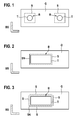
- FIG. 1 a battery system according to the invention according to a first embodiment is shown schematically.
- the battery system is called BS.
- B denotes a region of the housing G of the battery system BS and T denotes at least one terminal of the battery system BS. It may be the area B of a housing G of a battery cell, wherein the battery cell is part of the battery system BS.
- the at least one terminal T is suitable for making electrical contact with the battery system BS with another system.
- the at least one terminal T is arranged on the area B of the housing G.
- S denotes a predetermined breaking point.
- the predetermined breaking point S is suitable for detaching the region B from another region of the housing G under the action of pressure.
- the state of the battery system BS is shown prior to the onset of such pressure action resulting in the detachment of the area B of the housing G.
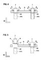
- FIG. 2 a battery system according to the invention according to a second embodiment is shown schematically.
- the battery system is called BS.
- B denotes a region of the housing G of the battery system BS and T denotes at least one terminal of the battery system BS. It may be the area B of a housing G of a Battery cell act, the battery cell is part of the battery system BS.
- the at least one terminal T is suitable for making electrical contact with the battery system BS with another system.
- the at least one terminal T is arranged on the area B of the housing G.
- S denotes a predetermined breaking point.
- the predetermined breaking point S is suitable for detaching the region B from another region of the housing G under the action of pressure.
- SN refers to a hinge.
- the hinge SN is formed as a connecting joint between the area B and the housing G. In the event that it comes to a breaking of the predetermined breaking point S under pressure, the area B is bent around the hinge SN around. In FIG. 2 For example, the state of the battery system BS is shown prior to the onset of such pressure action resulting in the detachment of the area B of the housing G.
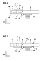
- FIG. 3 a battery system according to the invention according to a third embodiment is shown schematically.
- the battery system is called BS.
- B denotes a region of the housing G of the battery system BS and T denotes at least one terminal of the battery system BS. It may be the area B of a housing G of a battery cell, wherein the battery cell is part of the battery system BS.
- the at least one terminal T is suitable for making electrical contact with the battery system BS with another system.
- the at least one terminal T is arranged on the area B of the housing G.
- S and SK are designated breaking points.
- the predetermined breaking points S and SK are suitable for detaching the region B from another region of the housing G under the action of pressure. According to the in FIG.
- the terminal T may have been arranged in particular in the form of a film on the area B.
- the housing G on several predetermined breaking points.
- the designated breaking point SK has been generated such that the area B has been bonded to the housing G, wherein the adhesive zone acts as a predetermined breaking point SK.
- the adhesive zone is the area where the bond has been made.
- the predetermined breaking points S are arranged around the predetermined breaking point SK.
- the predetermined breaking points S and the predetermined breaking point SK are embodied on the housing G in such a way that the housing G is connected to a connecting region on which it is connected the area B, has a stable mechanical state.
- connection region at which the housing G is connected to the region B via the predetermined breaking points S and SK is in the stable mechanical state. After reaching a certain pressure value, the connection area bends outwards and passes through a metastable state. From the metastable state, the connection region moves again into another stable state, wherein in this other stable state, the predetermined breaking points S are torn. The rupture of the predetermined breaking points S then leads to a detachment of the region B from the housing G.
- FIG. 3 For example, the state of the battery system BS is shown prior to the onset of such pressure action resulting in the detachment of the area B of the housing G.
- a battery system according to the invention BS according to a fourth embodiment is shown schematically in a side view.
- S denotes predetermined breaking points.
- the predetermined breaking points S are suitable for detaching the region B from another region of the housing G under the action of pressure.
- STA designates current conductors, the current conductors STA electrically connecting the terminals T to a cathode or an anode of the battery system BS.
- AS a different predetermined breaking point is designated, wherein the other predetermined breaking point AS connects the at least one terminal T with a current conductor STA electrically conductive.
- the other predetermined breaking point AS is suitable for breaking under tensile action. The fact that there is a detachment of the area B under pressure, creates a pulling action between the at least one terminal T and the current collector STA. This pulling action leads to the breaking of the other predetermined breaking point AS.
- FIG. 5 a battery system according to the invention BS according to a fourth embodiment is shown schematically in a side view, after the emergence of a pressure B region of the housing G, on which the at least one terminal is disposed, has been detached from the other region of the housing G.
- an opening O in Housing G of the battery system BS has been created.
- substances can escape from the battery system BS.
- the fact that the substances emerge exactly at the location of the opening O prevents damage to the battery system BS elsewhere.
- a plurality of individual battery cells is arranged side by side, is thereby prevented that it comes to a damage of a battery cell by another battery cell.
- FIG. 6 a battery system according to the invention BS according to a fifth embodiment is shown schematically in a side view.
- S denotes a predetermined breaking point.
- the predetermined breaking point S is suitable for detaching the region B from another region of the housing G under the action of pressure.
- STA denotes a current conductor, the current conductor STA electrically connecting the terminal T to a cathode or an anode of the battery system BS.
- the current collector STA is electrically insulated from the housing G.
- the housing G between a first component T1 of the terminal T and a second component T2 of the terminal T is arranged.
- the two components T1 and T2 of the terminal T are connected through the housing G, by means of electrical lines L.
- the two components T1 and T2 of the terminal T and the electrical leads L are electrically insulated from the housing G.
- AS a different predetermined breaking point is designated, wherein the other predetermined breaking point AS connects the at least one terminal T with a current conductor STA electrically conductive.
- the other predetermined breaking point AS is for tearing suitable under tensile action.
- the other predetermined breaking point AS may be an electrically conductive wire.
- the at least one hinge SN refers to at least one hinge.
- the at least one hinge SN is formed as a connecting joint between the area B and the housing G.
- the area B is bent around the hinge SN around.
- the area B is bent around the hinge SN in the direction of rotation P6 according to this embodiment.
- FIG. 7 a battery system according to the invention BS according to a sixth embodiment is shown schematically in a side view.
- S denotes predetermined breaking points.
- the predetermined breaking points S are suitable for detaching the region B from another region of the housing G under the action of pressure.
- STA denotes a current conductor, the current conductor STA electrically connecting the terminal T to a cathode or an anode of the battery system BS.
- the housing G between a first component T1 of the terminal T and a second component T2 of the terminal T is arranged.
- the two components T1 and T2 of the terminal T are connected through the housing G by means of electrical lines L.
- the two components T1 and T2 of the terminal T and the electrical leads L are electrically insulated from the housing G.
- the other predetermined breaking point AS connects the at least one terminal T with a current conductor STA electrically conductive.
- the current collector STA is electrically insulated from the housing G.
- the current collector STA is designed, for example, stretchable or rupturable or breakable, so that it expands or tears under the effect of the action of pressure.
- the current collector STA can also be designed as a folded electrically conductive foil which unfolds under tension.
- the other predetermined breaking point AS is under breaking Tensile effect suitable.
- the other predetermined breaking point AS may be an electrically conductive wire.
- the hinge SN refers to a hinge.
- the hinge SN is formed as a connecting joint between the area B and the housing G.
- the housing G is bent around the hinge SN in the direction of rotation P7.
- the area B remains in its original position according to this embodiment.
- FIG. 8 a connection of a terminal T with a current collector STA via an inventive predetermined breaking point AS according to a first embodiment is shown schematically.
- the other predetermined breaking point AS connects the at least one terminal T with a current collector STA electrically conductive.
- the other predetermined breaking point AS is suitable for breaking up under breakage or tearing action. The fact that it comes to a detachment of a region B, on which the at least one terminal T is arranged, under pressure, creates a pulling action or shear force action between the at least one terminal T and the current collector STA. This pulling action or shear force action leads to the breaking of the other predetermined breaking point AS.
- FIG. 8 illustrated embodiment of the predetermined breaking point AS can in all, in the FIGS. 1 to 7 schematically illustrated embodiments of the battery system according to the invention can be applied.
- FIG. 9 a connection of a terminal T with a current collector STA via an inventive predetermined breaking point AS according to a second embodiment is shown schematically.
- the other predetermined breaking point is designed as an electrically conductive wire.
- the other predetermined breaking point AS is suitable for tearing.
- there is a detachment of a region B on which the at least one terminal T is arranged comes under pressure, creates a pulling action or shear force action between the at least one terminal T and the current collector STA.
- This pulling effect or shear force action leads to the breakage of the other predetermined breaking point AS.
- FIG. 9 illustrated embodiment of the predetermined breaking point AS can in all, in the FIGS. 1 to 7 schematically illustrated embodiments of the battery system according to the invention can be applied.
- FIG. 10 a connection of a terminal T with a current collector STA via an inventive predetermined breaking point AS according to a third embodiment is shown schematically.
- a plan view of the other predetermined breaking point AS according to the third embodiment is shown schematically.
- the other predetermined breaking point AS connects the at least one terminal T with a current collector STA electrically conductive.
- the other predetermined breaking point is formed according to this embodiment by an overlap of a part of the terminal T with a part of the current collector STA. The overlapping area is hatched. In this overlapping area, the current collector STA and the terminal T may have been glued or laminated together.
- the current collector STA and the terminal T are connected to each other via an electrically conductive connection V.
- the other predetermined breaking point AS is suitable for breaking up under breakage or tearing action.
- Part 10.2 a side view of the other predetermined breaking point AS shown schematically.
- the overlapping areas of the terminal T and of the current collector STA are denoted Tu and STAu, respectively.
- the state of the other predetermined breaking point AS is shown before a pressure.
- Part 10.3 a side view of the other predetermined breaking point AS shown schematically after a pressure.
- the area Tu has been deformed under pressure and bent away from the area STAu.
- By bending away the other predetermined breaking point AS has been broken and the electrical contact between the terminal T and the current conductor STA has been interrupted.
- FIG. 10 illustrated embodiment of the predetermined breaking point AS can in all, in the FIGS. 1 to 7 schematically illustrated embodiments of the battery system according to the invention can be applied.
Landscapes
- Engineering & Computer Science (AREA)
- Chemical & Material Sciences (AREA)
- Chemical Kinetics & Catalysis (AREA)
- Electrochemistry (AREA)
- General Chemical & Material Sciences (AREA)
- Power Engineering (AREA)
- Life Sciences & Earth Sciences (AREA)
- Sustainable Development (AREA)
- Sustainable Energy (AREA)
- Transportation (AREA)
- Mechanical Engineering (AREA)
- Connection Of Batteries Or Terminals (AREA)
Abstract
Description
- Aus dem Stand der Technik sind Vorrichtungen zur Erhöhung der Sicherheit von Batteriesystemen bekannt, wobei es sich bei diesen Vorrichtungen beispielsweise um Entgasungsvorrichtungen handeln kann. Bei den Entgasungsvorrichtungen kann es sich um Ventile oder Sollbruchstellen handeln, die an einem Bereich der Batteriesysteme angeordnet sind und zum Öffnen unter Druckeinwirkung geeignet sind.
- Dabei können zum Beispiel Sollbruchstellen insbesondere in Form von Perforationen auf einer Oberfläche des Batteriesystems ausgebildet sein. So zeigt beispielsweise die
DE 10 2010 001 533 A1 eine Entgasungsvorrichtung einer Batteriezelle, wobei es sich um eine Entgasungsvorrichtung in Form einer Mehrzahl von Materialschwächungen handelt, wobei die Materialschwächungen in einer Wand eines Gehäuses der Batteriezelle ausgebildet sind. - Die Erfindung geht aus von einem Batteriesystem, insbesondere einem LithiumIonen-Batteriesystem, mit mindestens einem Terminal, geeignet zur elektrischen Kontaktierung des Batteriesystems mit einem anderen System, wobei der mindestens eine Terminal auf einem Bereich eines Gehäuses des Batteriesystems angeordnet ist. Bei dem anderen System kann es sich beispielsweise um ein anderes Batteriesystem oder um einen Verbraucher handeln. Der Verbraucher wird über den mindestens einen Terminal mit elektrischer Energie aus dem Batteriesystem versorgt.
- Der Kern der Erfindung besteht darin, dass der Bereich des Gehäuses, auf dem der mindestens eine Terminal angeordnet ist, zum Ablösen von einem anderen Bereich des Gehäuses unter Druckeinwirkung geeignet ist.
- Durch den Umstand, dass der Bereich des Gehäuses, auf dem der mindestens eine Terminal angeordnet ist, zum Ablösen von einem anderen Bereich des Gehäuses unter Druckeinwirkung geeignet ist, kann der mindestens eine Terminal von einem elektrischen Energiespeicher innerhalb des Batteriesystems bei Anwachsen eines Druckes und/oder bei Entstehung eines Überdruckes getrennt werden.
- Hintergrund der Erfindung ist, dass im Falle eines entstehenden Überdrucks innerhalb eines Batteriesystems die elektrische Kontaktierung zwischen dem Batteriesystem und einem anderen System getrennt werden soll. Durch diese Trennung der elektrischen Kontaktierung werden unerwünschte elektrische Effekte, wie beispielsweise externe Kurzschlüsse oder Kriechströme, verhindert. Durch die Verhinderung unerwünschter elektrischer Effekte wird die Sicherheit im Umgang mit einem schadhaften Batteriesystem erhöht. Schadhaft kann das Batteriesystem insbesondere dann sein, wenn es zu einer Entstehung von Gasen im Inneren des Batteriesystems gekommen ist. Hintergrund der Erfindung ist somit ferner die Erhöhung der Sicherheit von Lebewesen oder Gegenständen, die sich im Umfeld des schadhaften Batteriesystems befinden.
- Erfindungsgemäß ist darüber hinaus die Verwendung eines Batteriesystems in einem Fahrzeug, insbesondere in einem Kraftfahrzeug.
- Bei einem Batteriesystem handelt es sich vorzugsweise um einen wiederaufladbaren elektrochemischen Energiespeicher. Das Batteriesystem enthält mindestens eine Batteriezelle und kann gegebenenfalls Vorrichtungen zur Steuerung der Batteriezelle enthalten. Die Batteriezelle kann auch mit anderen Batteriezellen innerhalb oder außerhalb des Batteriesystems elektrisch verbindbar ausgestaltet sein.
- Weitere vorteilhafte Ausführungen der Erfindung sind Gegenstand der Unteransprüche.
- Gemäß einer vorzugsweisen Ausgestaltungsform der Erfindung ist der mindestens eine Terminal zur elektrischen Kontaktierung mit einem Stromableiter geeignet. Dabei besteht zwischen dem mindestens einem Terminal und dem Stromableiter kein elektrischer Kontakt, wenn der Bereich des Gehäuses, auf dem der mindestens eine Terminal angeordnet ist, abgelöst ist.
- Entsprechend einer nächsten vorzugsweisen Ausgestaltungsform der Erfindung ist der Bereich des Gehäuses, auf dem der mindestens eine Terminal angeordnet ist, mit dem anderen Bereich des Gehäuses durch eine Sollbruchstelle und insbesondere durch einen perforierten oder geprägten Bereich des Gehäuses verbunden. Durch den Umstand, dass der Bereich des Gehäuses, auf dem der mindestens eine Terminal angeordnet ist, mit dem anderen Bereich des Gehäuses durch eine Sollbruchstelle und insbesondere durch einen perforierten oder geprägten Bereich des Gehäuses verbunden ist, kann die Ablösung des Bereichs des Gehäuses, auf dem der mindestens eine Terminal angeordnet ist, kontrolliert gestaltet werden. Durch die Perforation oder Prägung des Bereichs des Gehäuses kann insbesondere die Höhe des Drucks, der zur Ablösung des Bereichs des Gehäuses, auf dem der mindestens eine Terminal angeordnet ist, führen soll, eingestellt werden. Ein beispielhafter Druck, der zur Ablösung des Bereichs des Gehäuses, auf dem der mindestens eine Terminal angeordnet ist, führen soll, liegt bei 1 bar bis 10 bar, bevorzugt bei 3 bar bis 7 bar.
- Gemäß einer nächsten vorzugsweisen Ausgestaltungsform der Erfindung ist der Bereich des Gehäuses, auf dem der mindestens eine Terminal angeordnet ist, mit dem anderen Bereich des Gehäuses verklebt oder laminiert. Durch den Umstand, dass der Bereich des Gehäuses, auf dem der mindestens eine Terminal angeordnet ist, mit dem anderen Bereich des Gehäuses verklebt oder laminiert worden ist, kann die Druckeinwirkung, ab deren Überschreitung oder Erreichen der Bereich des Gehäuses, auf dem der mindestens eine Terminal angeordnet ist, abgelöst werden soll, vorgegeben werden.
- Gemäß einer nächsten vorzugsweisen Ausgestaltungsform der Erfindung ist der Stromableiter mit einer Anode oder Kathode des Batteriesystems durch eine andere Sollbruchstelle verbunden. Der Umstand, dass der Stromableiter mit einer Anode oder Kathode des Batteriesystems durch eine andere Sollbruchstelle verbunden ist, führt zu einer Erhöhung der Wirksamkeit der Erfindung, da eine zweite Einrichtung zur elektrischen Trennung bereit gestellt wird. Dadurch wird die Wahrscheinlichkeit des Eintretens von externen Kurzschlüssen oder Kriechströmen weiter verringert.
- Nachfolgend wird die Erfindung anhand von Ausführungsbeispielen, aus denen sich weitere erfinderische Merkmale ergeben können, auf die die Erfindung aber in ihrem Umfang nicht beschränkt ist, erläutert. Die Ausführungsbeispiele sind in den Figuren dargestellt. Es zeigt:
- Figur 1
- das erfindungsgemäße Batteriesystem gemäß einer ersten Ausführungsform;
- Figur 2
- das erfindungsgemäße Batteriesystem gemäß einer zweiten Ausführungsform;
- Figur 3
- das erfindungsgemäße Batteriesystem gemäß einer dritten Ausführungsform;
- Figur 4
- eine schematische Darstellung der Seitenansicht eines erfindungsgemäßen Batteriesystems gemäß einer vierten Ausführungsform;
- Figur 5
- die schematische Darstellung der Seitenansicht eines erfindungsgemäßen Batteriesystems gemäß einer vierten Ausführungsform nach Entstehen einer Druckeinwirkung, die zur Ablösung eines Bereichs des Gehäuses des Batteriesystems geführt hat;
- Figur 6
- eine schematische Darstellung der Seitenansicht eines erfindungsgemäßen Batteriesystems gemäß einer fünften Ausführungsform;
- Figur 7
- eine schematische Darstellung der Seitenansicht eines erfindungsgemäßen Batteriesystems gemäß einer sechsten Ausführungsform;
- Figur 8
- eine schematische Darstellung einer Verbindung eines Terminals mit einem Stromableiter über eine erfindungsgemäße andere Sollbruchstelle gemäß einer ersten Ausführungsform;
- Figur 9
- eine schematische Darstellung einer Verbindung eines Terminals mit einem Stromableiter über eine erfindungsgemäße andere Sollbruchstelle gemäß einer zweiten Ausführungsform;
- Figur 10
- eine schematische Darstellung einer Verbindung eines Terminals mit einem Stromableiter über eine erfindungsgemäße andere Sollbruchstelle gemäß einer dritten Ausführungsform.
- In
Figur 1 ist ein erfindungsgemäßes Batteriesystem gemäß einer ersten Ausführungsform schematisch dargestellt. Das Batteriesystem wird mit BS bezeichnet. Mit B wird ein Bereich des Gehäuses G des Batteriesystems BS bezeichnet und mit T wird mindestens ein Terminal des Batteriesystems BS bezeichnet. Es kann sich um den Bereich B eines Gehäuses G einer Batteriezelle handeln, wobei die Batteriezelle Bestandteil des Batteriesystems BS ist. Der mindestens eine Terminal T ist zur elektrischen Kontaktierung des Batteriesystems BS mit einem anderen System geeignet. Der mindestens eine Terminal T ist auf dem Bereich B des Gehäuses G angeordnet. Mit S wird eine Sollbruchstelle bezeichnet. Die Sollbruchstelle S ist zum Ablösen des Bereichs B von einem anderen Bereich des Gehäuses G unter Druckeinwirkung geeignet. InFigur 1 ist der Zustand des Batteriesystems BS vor Einsetzen einer solchen Druckeinwirkung, die zum Ablösen des Bereichs B des Gehäuses G führt, dargestellt. - In
Figur 2 ist ein erfindungsgemäßes Batteriesystem gemäß einer zweiten Ausführungsform schematisch dargestellt. Das Batteriesystem wird mit BS bezeichnet. Mit B wird ein Bereich des Gehäuses G des Batteriesystems BS bezeichnet und mit T wird mindestens ein Terminal des Batteriesystems BS bezeichnet. Es kann sich um den Bereich B eines Gehäuses G einer Batteriezelle handeln, wobei die Batteriezelle Bestandteil des Batteriesystems BS ist. Der mindestens eine Terminal T ist zur elektrischen Kontaktierung des Batteriesystems BS mit einem anderen System geeignet. Der mindestens eine Terminal T ist auf dem Bereich B des Gehäuses G angeordnet. Mit S wird eine Sollbruchstelle bezeichnet. Die Sollbruchstelle S ist zum Ablösen des Bereichs B von einem anderen Bereich des Gehäuses G unter Druckeinwirkung geeignet. Mit SN wird ein Scharnier bezeichnet. Das Scharnier SN ist als verbindendes Gelenk zwischen dem Bereich B und dem Gehäuse G ausgebildet. Für den Fall, dass es zum einem Aufbrechen der Sollbruchstelle S unter Druckeinwirkung kommt, wird der Bereich B um das Scharnier SN herum aufgebogen. InFigur 2 ist der Zustand des Batteriesystems BS vor Einsetzen einer solchen Druckeinwirkung, die zum Ablösen des Bereichs B des Gehäuses G führt, dargestellt. - In
Figur 3 ist ein erfindungsgemäßes Batteriesystem gemäß einer dritten Ausführungsform schematisch dargestellt. Das Batteriesystem wird mit BS bezeichnet. Mit B wird ein Bereich des Gehäuses G des Batteriesystems BS bezeichnet und mit T wird mindestens ein Terminal des Batteriesystems BS bezeichnet. Es kann sich um den Bereich B eines Gehäuses G einer Batteriezelle handeln, wobei die Batteriezelle Bestandteil des Batteriesystems BS ist. Der mindestens eine Terminal T ist zur elektrischen Kontaktierung des Batteriesystems BS mit einem anderen System geeignet. Der mindestens eine Terminal T ist auf dem Bereich B des Gehäuses G angeordnet. Mit S und SK werden Sollbruchstellen bezeichnet. Die Sollbruchstellen S und SK sind zum Ablösen des Bereichs B von einem anderen Bereich des Gehäuses G unter Druckeinwirkung geeignet. Gemäß der inFigur 3 dargestellten Ausführungsform kann der Terminal T insbesondere in Form einer Folie auf dem Bereich B angeordnet worden sein. Gemäß der inFigur 3 dargestellten Ausführungsform weist das Gehäuse G mehrere Sollbruchstellen auf. Die mit SK bezeichnete Sollbruchstelle ist derart erzeugt worden, dass der Bereich B mit dem Gehäuse G verklebt worden ist, wobei die Klebezone als Sollbruchstelle SK wirkt. Als Klebezone wird der Bereich bezeichnet, an dem die Verklebung vorgenommen worden ist. Um die Sollbruchstelle SK sind die Sollbruchstellen S angeordnet. Die Sollbruchstellen S und die Sollbruchstelle SK sind derart auf dem Gehäuse G ausgeführt, dass das Gehäuse G an einem Verbindungsbereich, an dem es mit dem Bereich B verbunden ist, einen stabilen mechanischen Zustand aufweist. Vor einer möglichen Druckeinwirkung befindet sich der Verbindungsbereich, an dem das Gehäuse G mit dem Bereich B über die Sollbruchstellen S und SK verbunden ist, in dem stabilen mechanischen Zustand. Nach Erreichen eines bestimmten Druckwertes biegt sich der Verbindungsbereich nach außen und durchläuft einen metastabilen Zustand. Aus dem metastabilen Zustand heraus bewegt sich der Verbindungsbereich wieder in einen anderen stabilen Zustand, wobei in diesem anderen stabilen Zustand die Sollbruchstellen S aufgerissen sind. Das Aufreißen der Sollbruchstellen S führt dann zu einem Ablösen des Bereichs B von dem Gehäuse G. - In
Figur 3 ist der Zustand des Batteriesystems BS vor Einsetzen einer solchen Druckeinwirkung, die zum Ablösen des Bereichs B des Gehäuses G führt, dargestellt. - In
Figur 4 ist ein erfindungsgemäßes Batteriesystem BS gemäß einer vierten Ausführungsform in einer Seitenansicht schematisch dargestellt. Mit S werden Sollbruchstellen bezeichnet. Die Sollbruchstellen S sind zum Ablösen des Bereichs B von einem anderen Bereich des Gehäuses G unter Druckeinwirkung geeignet. Mit STA werden Stromableiter bezeichnet, wobei die Stromableiter STA die Terminals T mit einer Kathode oder einer Anode des Batteriesystems BS elektrisch leitend verbinden. Mit AS wird eine andere Sollbruchstelle bezeichnet, wobei die andere Sollbruchstelle AS den mindestens einen Terminal T mit einem Stromableiter STA elektrisch leitend verbindet. Die andere Sollbruchstelle AS ist zum Aufbrechen unter Zugwirkung geeignet. Dadurch, dass es zu einem Ablösen des Bereichs B unter Druckeinwirkung kommt, entsteht eine Zugwirkung zwischen dem mindestens einen Terminal T und dem Stromableiter STA. Diese Zugwirkung führt zum Aufbrechen der anderen Sollbruchstelle AS. - In
Figur 5 ist ein erfindungsgemäßes Batteriesystem BS gemäß einer vierten Ausführungsform in einer Seitenansicht schematisch dargestellt, nachdem durch Entstehen einer Druckeinwirkung der Bereich B des Gehäuses G, auf dem der mindestens eine Terminal angeordnet ist, von dem anderen Bereich des Gehäuses G abgelöst worden ist. Durch die Ablösung ist eine Öffnung O im Gehäuse G des Batteriesystems BS geschaffen worden. Durch die Öffnung O können Substanzen aus dem Batteriesystem BS austreten. Der Umstand, dass die Substanzen genau am Ort der Öffnung O austreten, verhindert die Schädigung des Batteriesystems BS an anderer Stelle. Insbesondere für den Fall, dass eine Mehrzahl von einzelnen Batteriezellen nebeneinander angeordnet ist, wird dadurch verhindert, dass es zu einer Schädigung einer Batteriezelle durch eine andere Batteriezelle kommt. Darüber hinaus ist auf diese Weise durch die Druckeinwirkung der mindestens eine Terminal T von dem Stromableiter STA elektrisch getrennt worden. Diese elektrische Trennung des mindestens einen Terminals T von dem Stromableiter STA ist einfacher und kostengünstiger zu realisieren als beispielsweise eine Trennung über eine Schmelzsicherung. Darüber hinaus wird die Wahrscheinlichkeit des Entstehens eines unerwünschten externen Kurzschlusses verhindert. Hintergrund ist somit auch die Vermeidung von unerwünschten Effekten, die im Gebrauch von Schmelzsicherungen entstehen können. Zu den unerwünschten Effekten im Gebrauch von Schmelzsicherungen zählen beispielsweise interne Kurzschlüsse im Batteriesystem BS sowie Kriechströme und Brände innerhalb des Batteriesystems BS. - In
Figur 6 ist ein erfindungsgemäßes Batteriesystem BS gemäß einer fünften Ausführungsform in einer Seitenansicht schematisch dargestellt. Mit S wird eine Sollbruchstelle bezeichnet. Die Sollbruchstelle S ist zum Ablösen des Bereichs B von einem anderen Bereich des Gehäuses G unter Druckeinwirkung geeignet. Mit STA wird ein Stromableiter bezeichnet, wobei der Stromableiter STA den Terminal T mit einer Kathode oder einer Anode des Batteriesystems BS elektrisch leitend verbindet. Der Stromableiter STA ist gegenüber dem Gehäuse G elektrisch isoliert. Gemäß der inFigur 6 dargestellten Ausführungsform ist das Gehäuse G zwischen einem ersten Bestandteil T1 des Terminals T und einem zweiten Bestandteil T2 des Terminals T angeordnet. Die beiden Bestandteile T1 und T2 des Terminals T sind, durch das Gehäuse G hindurch, mittels elektrischer Leitungen L verbunden. Die beiden Bestandteile T1 und T2 des Terminals T und die elektrischen Leitungen L sind gegenüber dem Gehäuse G elektrisch isoliert. Mit AS wird eine andere Sollbruchstelle bezeichnet, wobei die andere Sollbruchstelle AS den mindestens einen Terminal T mit einem Stromableiter STA elektrisch leitend verbindet. Die andere Sollbruchstelle AS ist zum Reißen unter Zugwirkung geeignet. Insbesondere kann es sich bei der anderen Sollbruchstelle AS um einen elektrisch leitenden Draht handeln. - Dadurch, dass es zu einem Ablösen des Bereichs B unter Druckeinwirkung kommt, entsteht eine Zugwirkung zwischen dem Bestandteil T2 des Terminals T und dem Stromableiter STA. Diese Zugwirkung führt zum Aufreißen der anderen Sollbruchstelle AS.
- Mit SN wird mindestens ein Scharnier bezeichnet. Das mindestens eine Scharnier SN ist als verbindendes Gelenk zwischen dem Bereich B und dem Gehäuse G ausgebildet. Für den Fall, dass es zum einem Aufbrechen der Sollbruchstelle S unter Druckeinwirkung kommt, wird der Bereich B um das Scharnier SN herum aufgebogen. Der Bereich B wird gemäß dieser Ausführungsform um das Scharnier SN herum in Rotationsrichtung P6 gebogen.
- In
Figur 7 ist ein erfindungsgemäßes Batteriesystem BS gemäß einer sechsten Ausführungsform in einer Seitenansicht schematisch dargestellt. Mit S werden Sollbruchstellen bezeichnet. Die Sollbruchstellen S sind zum Ablösen des Bereichs B von einem anderen Bereich des Gehäuses G unter Druckeinwirkung geeignet. Mit STA wird ein Stromableiter bezeichnet, wobei der Stromableiter STA den Terminal T mit einer Kathode oder einer Anode des Batteriesystems BS elektrisch leitend verbindet. Gemäß der inFigur 6 dargestellten Ausführungsform ist das Gehäuse G zwischen einem ersten Bestandteil T1 des Terminals T und einem zweiten Bestandteil T2 des Terminals T angeordnet. Die beiden Bestandteile T1 und T2 des Terminals T sind durch das Gehäuse G hindurch mittels elektrischer Leitungen L verbunden. Die beiden Bestandteile T1 und T2 des Terminals T und die elektrischen Leitungen L sind gegenüber dem Gehäuse G elektrisch isoliert. - Mit AS wird eine andere Sollbruchstelle bezeichnet, wobei die andere Sollbruchstelle AS den mindestens einen Terminal T mit einem Stromableiter STA elektrisch leitend verbindet. Der Stromableiter STA ist gegenüber dem Gehäuse G elektrisch isoliert. Der Stromableiter STA ist beispielsweise dehnbar oder reißbar oder brechbar ausgestaltet, so dass er unter Zugeinwirkung oder Druckeinwirkung sich dehnt oder auseinanderreißt. Der Stromableiter STA kann auch als gefaltete elektrisch leitende Folie ausgelegt sein, die sich unter Zugwirkung entfaltet. Die andere Sollbruchstelle AS ist zum Reißen unter Zugwirkung geeignet. Insbesondere kann es sich bei der anderen Sollbruchstelle AS um einen elektrisch leitenden Draht handeln.
- Dadurch, dass es zu einem Ablösen des Bereichs B unter Druckeinwirkung kommt, entsteht eine Zugwirkung zwischen dem Bestandteil T2 des Terminals T und dem Stromableiter STA. Diese Zugwirkung führt zum Aufreißen der anderen Sollbruchstelle AS.
- Mit SN wird ein Scharnier bezeichnet. Das Scharnier SN ist als verbindendes Gelenk zwischen dem Bereich B und dem Gehäuse G ausgebildet. Für den Fall, dass es zum einem Aufbrechen der Sollbruchstelle S unter Druckeinwirkung kommt, wird das Gehäuse G um das Scharnier SN herum in Rotationsrichtung P7 aufgebogen. Der Bereich B verbleibt gemäß dieser Ausführungsform in seiner ursprünglichen Position.
- In
Figur 8 ist eine Verbindung eines Terminals T mit einem Stromableiter STA über eine erfindungsgemäße andere Sollbruchstelle AS gemäß einer ersten Ausführungsform schematisch dargestellt. Die andere Sollbruchstelle AS verbindet den mindestens einen Terminal T mit einem Stromableiter STA elektrisch leitend. Die andere Sollbruchstelle AS ist zum Aufbrechen unter Bruchwirkung oder Reißwirkung geeignet. Dadurch, dass es zu einem Ablösen eines Bereichs B, auf dem der mindestens eine Terminal T angeordnet ist, unter Druckeinwirkung kommt, entsteht eine Zugwirkung oder Scherkraftwirkung zwischen dem mindestens einen Terminal T und dem Stromableiter STA. Diese Zugwirkung oder Scherkraftwirkung führt zum Aufbrechen der anderen Sollbruchstelle AS. Die inFigur 8 dargestellte Ausführungsform der Sollbruchstelle AS kann in sämtlichen, in denFiguren 1 bis 7 schematisch dargestellten, Ausführungsformen des erfindungsgemäßen Batteriesystems angewendet werden. - In
Figur 9 ist eine Verbindung eines Terminals T mit einem Stromableiter STA über eine erfindungsgemäße andere Sollbruchstelle AS gemäß einer zweiten Ausführungsform schematisch dargestellt. Im Unterschied zu der inFigur 8 dargestellten Ausführungsform, ist die andere Sollbruchstelle als elektrisch leitender Draht ausgeführt. Die andere Sollbruchstelle AS ist zum Reißen geeignet. Dadurch, dass es zu einem Ablösen eines Bereichs B, auf dem der mindestens eine Terminal T angeordnet ist, unter Druckeinwirkung kommt, entsteht eine Zugwirkung oder Scherkraftwirkung zwischen dem mindestens einen Terminal T und dem Stromableiter STA. Diese Zugwirkung oder Scherkraftwirkung führt zum Reißen der anderen Sollbruchstelle AS. Die inFigur 9 dargestellte Ausführungsform der Sollbruchstelle AS kann in sämtlichen, in denFiguren 1 bis 7 schematisch dargestellten, Ausführungsformen des erfindungsgemäßen Batteriesystems angewendet werden. - In
Figur 10 ist eine Verbindung eines Terminals T mit einem Stromableiter STA über eine erfindungsgemäße andere Sollbruchstelle AS gemäß einer dritten Ausführungsform schematisch dargestellt. - In Teilfigur 10.1 ist eine Aufsicht auf die andere Sollbruchstelle AS gemäß der dritten Ausführungsform schematisch dargestellt. Die andere Sollbruchstelle AS verbindet den mindestens einen Terminal T mit einem Stromableiter STA elektrisch leitend. Die andere Sollbruchstelle wird gemäß dieser Ausführungsform durch eine Überlappung eines Teils des Terminals T mit einem Teil des Stromableiters STA gebildet. Der überlappende Bereich ist schraffiert dargestellt. In diesem überlappenden Bereich können der Stromableiter STA und der Terminal T zusammenklebt oder zusammenlaminiert worden sein. Der Stromableiter STA und der Terminal T sind über eine elektrische leitfähige Verbindung V miteinander verbunden.
- Die andere Sollbruchstelle AS ist zum Aufbrechen unter Bruchwirkung oder Reißwirkung geeignet. Dadurch, dass es zu einem Ablösen eines Bereichs B, auf dem der mindestens eine Terminal T angeordnet ist, unter Druckeinwirkung kommt, entsteht eine Zugwirkung oder Scherkraftwirkung zwischen dem mindestens einen Terminal T und dem Stromableiter STA. Diese Zugwirkung oder Scherkraftwirkung führt zum Aufbrechen der anderen Sollbruchstelle AS.
- In Teilfigur 10.2 eine Seitenansicht der anderen Sollbruchstelle AS schematisch dargestellt. Die sich überlappenden Bereiche des Terminals T und des Stromableiters STA werden mit Tu beziehungsweise mit STAu bezeichnet. In Teilfigur 10.2 ist der Zustand der anderen Sollbruchstelle AS vor einer Druckeinwirkung dargestellt.
- In Teilfigur 10.3 eine Seitenansicht der anderen Sollbruchstelle AS nach einer Druckeinwirkung schematisch dargestellt. Der Bereich Tu ist dabei unter Druckeinwirkung verformt und von dem Bereich STAu weggebogen worden. Durch das Wegbiegen ist die andere Sollbruchstelle AS aufgebrochen worden und der elektrische Kontakt zwischen dem Terminal T und dem Stromableiter STA unterbrochen worden.
- Die in
Figur 10 dargestellte Ausführungsform der Sollbruchstelle AS kann in sämtlichen, in denFiguren 1 bis 7 schematisch dargestellten, Ausführungsformen des erfindungsgemäßen Batteriesystems angewendet werden.
Claims (6)
- Batteriesystem (BS), insbesondere Lithium-Ionen-Batteriesystem, mit mindestens einem Terminal (T), geeignet zur elektrischen Kontaktierung des Batteriesystems (BS) mit einem anderen System, wobei der mindestens eine Terminal (T) auf einem Bereich (B) eines Gehäuses (G) des Batteriesystems (BS) angeordnet ist, dadurch gekennzeichnet, dass der Bereich (B) des Gehäuses (G), auf dem der mindestens eine Terminal (T) angeordnet ist, zum Ablösen von einem anderen Bereich des Gehäuses (G) unter Druckeinwirkung geeignet ist.
- Batteriesystem (BS) nach Anspruch 1, dadurch gekennzeichnet, dass der mindestens eine Terminal (T) zur elektrischen Kontaktierung mit einem Stromableiter (STA) geeignet ist, wobei zwischen dem mindestens einen Terminal (T) und dem Stromableiter (STA) kein elektrischer Kontakt besteht, wenn der Bereich (B) des Gehäuses (G), auf dem der mindestens eine Terminal (T) angeordnet ist, abgelöst ist.
- Batteriesystem (BS) nach Anspruch 1 oder 2, dadurch gekennzeichnet, dass der Bereich (B) des Gehäuses (G), auf dem der mindestens eine Terminal (T) angeordnet ist, mit dem anderen Bereich des Gehäuses (G) durch eine Sollbruchstelle (S, SK) und insbesondere durch einen perforierten oder geprägten Bereich des Gehäuses (G) verbunden ist.
- Batteriesystem (BS) nach einem der vorhergehenden Ansprüche, dadurch gekennzeichnet, dass der Bereich (B) des Gehäuses (G), auf dem der mindestens eine Terminal (T) angeordnet ist, mit dem anderen Bereich des Gehäuses (G) verklebt oder laminiert worden ist.
- Batteriesystem (BS) nach einem der vorhergehenden Ansprüche, dadurch gekennzeichnet, dass Stromableiter (STA) und/oder der mindestens eine Terminal (T) mit einer Anode oder einer Kathode des Batteriesystems (BS) durch eine andere Sollbruchstelle (AS) verbunden ist.
- Verwendung eines Batteriesystems (BS) nach einem der Ansprüche 1 bis 5 in einem Fahrzeug, insbesondere in einem Kraftfahrzeug.
Priority Applications (1)
| Application Number | Priority Date | Filing Date | Title |
|---|---|---|---|
| EP15190438.0A EP3159952B1 (de) | 2015-10-19 | 2015-10-19 | Sicherheitsvorrichtung für batteriesysteme |
Applications Claiming Priority (1)
| Application Number | Priority Date | Filing Date | Title |
|---|---|---|---|
| EP15190438.0A EP3159952B1 (de) | 2015-10-19 | 2015-10-19 | Sicherheitsvorrichtung für batteriesysteme |
Publications (2)
| Publication Number | Publication Date |
|---|---|
| EP3159952A1 true EP3159952A1 (de) | 2017-04-26 |
| EP3159952B1 EP3159952B1 (de) | 2019-12-11 |
Family
ID=54337166
Family Applications (1)
| Application Number | Title | Priority Date | Filing Date |
|---|---|---|---|
| EP15190438.0A Active EP3159952B1 (de) | 2015-10-19 | 2015-10-19 | Sicherheitsvorrichtung für batteriesysteme |
Country Status (1)
| Country | Link |
|---|---|
| EP (1) | EP3159952B1 (de) |
Cited By (2)
| Publication number | Priority date | Publication date | Assignee | Title |
|---|---|---|---|---|
| CN114976523A (zh) * | 2021-02-26 | 2022-08-30 | 大众汽车股份公司 | 带有接线柱的蓄电池单体、蓄电池系统和机动车 |
| CN116783766A (zh) * | 2021-04-07 | 2023-09-19 | 宝马股份公司 | 具有侧向单体接触系统的电蓄能器和机动车 |
Citations (4)
| Publication number | Priority date | Publication date | Assignee | Title |
|---|---|---|---|---|
| JP2001126694A (ja) * | 1999-10-28 | 2001-05-11 | Fdk Corp | 円筒形アルカリ電池の防爆式密閉構造 |
| US20100316894A1 (en) * | 2009-06-12 | 2010-12-16 | Tesla Motors, Inc. | Integrated battery pressure relief and terminal isolation system |
| DE102010001533A1 (de) | 2010-02-03 | 2011-08-04 | SB LiMotive Company Ltd., Kyonggi | Batteriezelle mit einem Sicherheitsventil zur Entlüftung und Verfahren zur Herstellung eines Sicherheitsventils in einem Batteriegehäuse |
| EP2884563A1 (de) * | 2012-10-18 | 2015-06-17 | LG Chem, Ltd. | Elektrodenleitung und sekundärbatterie damit |
-
2015
- 2015-10-19 EP EP15190438.0A patent/EP3159952B1/de active Active
Patent Citations (4)
| Publication number | Priority date | Publication date | Assignee | Title |
|---|---|---|---|---|
| JP2001126694A (ja) * | 1999-10-28 | 2001-05-11 | Fdk Corp | 円筒形アルカリ電池の防爆式密閉構造 |
| US20100316894A1 (en) * | 2009-06-12 | 2010-12-16 | Tesla Motors, Inc. | Integrated battery pressure relief and terminal isolation system |
| DE102010001533A1 (de) | 2010-02-03 | 2011-08-04 | SB LiMotive Company Ltd., Kyonggi | Batteriezelle mit einem Sicherheitsventil zur Entlüftung und Verfahren zur Herstellung eines Sicherheitsventils in einem Batteriegehäuse |
| EP2884563A1 (de) * | 2012-10-18 | 2015-06-17 | LG Chem, Ltd. | Elektrodenleitung und sekundärbatterie damit |
Cited By (2)
| Publication number | Priority date | Publication date | Assignee | Title |
|---|---|---|---|---|
| CN114976523A (zh) * | 2021-02-26 | 2022-08-30 | 大众汽车股份公司 | 带有接线柱的蓄电池单体、蓄电池系统和机动车 |
| CN116783766A (zh) * | 2021-04-07 | 2023-09-19 | 宝马股份公司 | 具有侧向单体接触系统的电蓄能器和机动车 |
Also Published As
| Publication number | Publication date |
|---|---|
| EP3159952B1 (de) | 2019-12-11 |
Similar Documents
| Publication | Publication Date | Title |
|---|---|---|
| EP2831937B1 (de) | Zellverbinder für ein batteriesystem oder für eine batteriezelle eines elektrischen energiespeichers, batterie und kraftfahrzeug | |
| EP2961558B1 (de) | Hochvolt-energiespeichermodul und verfahren zur herstellung des hochvolt-energiespeichermoduls | |
| EP3350851B1 (de) | Batteriemodul, verfahren zu dessen herstellung sowie batterie | |
| DE102013220044B4 (de) | Zellkontaktierungssystem für eine elektrochemische Vorrichtung und Verfahren zum Herstellen eines Zellkontaktierungssystems | |
| DE102017106068A1 (de) | Batteriesystem | |
| EP2642582A2 (de) | Elektrisches Überbrückungselement, insbesondere für Speicherzellen eines Energiespeichers | |
| EP2779271A2 (de) | Sicherheitselement für Batteriezelle | |
| DE102018212913A1 (de) | Leitermodul | |
| DE102018201995A1 (de) | Pyrotechnischer Schalter | |
| EP3159952B1 (de) | Sicherheitsvorrichtung für batteriesysteme | |
| DE102016208421A1 (de) | Elektrische Energiespeicherzelle mit integrierter Überbrückungseinrichtung | |
| WO2011116802A1 (de) | Einzelzelle für eine batterie | |
| DE102014117313A1 (de) | Gehäuseteil eines Gehäuses einer Hochvoltkomponente eines Kraftfahrzeugs | |
| DE102022119479A1 (de) | Bauteilanordnung für eine Hochvoltbatterie und Verfahren zum Herstellen einer Bauteilanordnung | |
| WO2016071100A1 (de) | Batterie mit verbesserter sicherheit | |
| DE102021117243A1 (de) | Verfahren zum Bereitstellen einer Isolierung zwischen zwei Rundzellen eines Zellmoduls und Zellmodul | |
| DE102012001150A1 (de) | Stromkabel, Vorrichtung mit dem Stromkabel und Verfahren zum spannungsfrei Schalten von zumindest einem Abschnitt eines elektrischen Leiters des Stromkabels | |
| DE102017208395A1 (de) | Verfahren zum Anordnen eines Kontaktelements, Kontaktelement sowie Batteriestapel | |
| EP1130687B1 (de) | Elektrisches Flachbandkabel mit gefalteten elektrischen Leiterbahnen | |
| DE102015005835B4 (de) | Energiespeichermodul, Kraftfahrzeug und Verfahren zum Erzeugen einer Fügeverbindung | |
| DE102021005067A1 (de) | Fahrzeugbatterie und Zellverbindungssystem dafür | |
| EP2735040B1 (de) | Hochvoltspeicher | |
| DE102013006806A1 (de) | Kabelschuh mit integrierter Schmelzsicherung | |
| DE102010034368B4 (de) | Elektrischer Energiespeicher | |
| DE60306100T2 (de) | Elektrochemischer Generator mit Monoblock-Konnektor |
Legal Events
| Date | Code | Title | Description |
|---|---|---|---|
| PUAI | Public reference made under article 153(3) epc to a published international application that has entered the european phase |
Free format text: ORIGINAL CODE: 0009012 |
|
| STAA | Information on the status of an ep patent application or granted ep patent |
Free format text: STATUS: THE APPLICATION HAS BEEN PUBLISHED |
|
| AK | Designated contracting states |
Kind code of ref document: A1 Designated state(s): AL AT BE BG CH CY CZ DE DK EE ES FI FR GB GR HR HU IE IS IT LI LT LU LV MC MK MT NL NO PL PT RO RS SE SI SK SM TR |
|
| AX | Request for extension of the european patent |
Extension state: BA ME |
|
| STAA | Information on the status of an ep patent application or granted ep patent |
Free format text: STATUS: REQUEST FOR EXAMINATION WAS MADE |
|
| 17P | Request for examination filed |
Effective date: 20171026 |
|
| RBV | Designated contracting states (corrected) |
Designated state(s): AL AT BE BG CH CY CZ DE DK EE ES FI FR GB GR HR HU IE IS IT LI LT LU LV MC MK MT NL NO PL PT RO RS SE SI SK SM TR |
|
| STAA | Information on the status of an ep patent application or granted ep patent |
Free format text: STATUS: EXAMINATION IS IN PROGRESS |
|
| 17Q | First examination report despatched |
Effective date: 20180927 |
|
| RAP1 | Party data changed (applicant data changed or rights of an application transferred) |
Owner name: GS YUASA INTERNATIONAL LTD. Owner name: ROBERT BOSCH GMBH |
|
| RIC1 | Information provided on ipc code assigned before grant |
Ipc: H01M 2/34 20060101ALI20190415BHEP Ipc: H01M 2/26 20060101ALI20190415BHEP Ipc: H01M 10/0525 20100101ALN20190415BHEP Ipc: H01M 2/30 20060101ALI20190415BHEP Ipc: H01M 2/12 20060101AFI20190415BHEP Ipc: B60L 50/64 20190101ALI20190415BHEP Ipc: B60L 3/00 20190101ALI20190415BHEP Ipc: B60L 3/04 20060101ALI20190415BHEP |
|
| GRAP | Despatch of communication of intention to grant a patent |
Free format text: ORIGINAL CODE: EPIDOSNIGR1 |
|
| STAA | Information on the status of an ep patent application or granted ep patent |
Free format text: STATUS: GRANT OF PATENT IS INTENDED |
|
| INTG | Intention to grant announced |
Effective date: 20190531 |
|
| GRAS | Grant fee paid |
Free format text: ORIGINAL CODE: EPIDOSNIGR3 |
|
| GRAA | (expected) grant |
Free format text: ORIGINAL CODE: 0009210 |
|
| STAA | Information on the status of an ep patent application or granted ep patent |
Free format text: STATUS: THE PATENT HAS BEEN GRANTED |
|
| AK | Designated contracting states |
Kind code of ref document: B1 Designated state(s): AL AT BE BG CH CY CZ DE DK EE ES FI FR GB GR HR HU IE IS IT LI LT LU LV MC MK MT NL NO PL PT RO RS SE SI SK SM TR |
|
| REG | Reference to a national code |
Ref country code: GB Ref legal event code: FG4D Free format text: NOT ENGLISH |
|
| REG | Reference to a national code |
Ref country code: CH Ref legal event code: EP |
|
| REG | Reference to a national code |
Ref country code: AT Ref legal event code: REF Ref document number: 1213086 Country of ref document: AT Kind code of ref document: T Effective date: 20191215 |
|
| REG | Reference to a national code |
Ref country code: DE Ref legal event code: R096 Ref document number: 502015011188 Country of ref document: DE |
|
| REG | Reference to a national code |
Ref country code: IE Ref legal event code: FG4D Free format text: LANGUAGE OF EP DOCUMENT: GERMAN |
|
| REG | Reference to a national code |
Ref country code: NL Ref legal event code: MP Effective date: 20191211 |
|
| REG | Reference to a national code |
Ref country code: LT Ref legal event code: MG4D |
|
| RAP2 | Party data changed (patent owner data changed or rights of a patent transferred) |
Owner name: GS YUASA INTERNATIONAL LTD. Owner name: ROBERT BOSCH GMBH |
|
| PG25 | Lapsed in a contracting state [announced via postgrant information from national office to epo] |
Ref country code: NO Free format text: LAPSE BECAUSE OF FAILURE TO SUBMIT A TRANSLATION OF THE DESCRIPTION OR TO PAY THE FEE WITHIN THE PRESCRIBED TIME-LIMIT Effective date: 20200311 Ref country code: GR Free format text: LAPSE BECAUSE OF FAILURE TO SUBMIT A TRANSLATION OF THE DESCRIPTION OR TO PAY THE FEE WITHIN THE PRESCRIBED TIME-LIMIT Effective date: 20200312 Ref country code: FI Free format text: LAPSE BECAUSE OF FAILURE TO SUBMIT A TRANSLATION OF THE DESCRIPTION OR TO PAY THE FEE WITHIN THE PRESCRIBED TIME-LIMIT Effective date: 20191211 Ref country code: BG Free format text: LAPSE BECAUSE OF FAILURE TO SUBMIT A TRANSLATION OF THE DESCRIPTION OR TO PAY THE FEE WITHIN THE PRESCRIBED TIME-LIMIT Effective date: 20200311 Ref country code: LT Free format text: LAPSE BECAUSE OF FAILURE TO SUBMIT A TRANSLATION OF THE DESCRIPTION OR TO PAY THE FEE WITHIN THE PRESCRIBED TIME-LIMIT Effective date: 20191211 Ref country code: LV Free format text: LAPSE BECAUSE OF FAILURE TO SUBMIT A TRANSLATION OF THE DESCRIPTION OR TO PAY THE FEE WITHIN THE PRESCRIBED TIME-LIMIT Effective date: 20191211 Ref country code: SE Free format text: LAPSE BECAUSE OF FAILURE TO SUBMIT A TRANSLATION OF THE DESCRIPTION OR TO PAY THE FEE WITHIN THE PRESCRIBED TIME-LIMIT Effective date: 20191211 |
|
| PG25 | Lapsed in a contracting state [announced via postgrant information from national office to epo] |
Ref country code: HR Free format text: LAPSE BECAUSE OF FAILURE TO SUBMIT A TRANSLATION OF THE DESCRIPTION OR TO PAY THE FEE WITHIN THE PRESCRIBED TIME-LIMIT Effective date: 20191211 Ref country code: RS Free format text: LAPSE BECAUSE OF FAILURE TO SUBMIT A TRANSLATION OF THE DESCRIPTION OR TO PAY THE FEE WITHIN THE PRESCRIBED TIME-LIMIT Effective date: 20191211 |
|
| PG25 | Lapsed in a contracting state [announced via postgrant information from national office to epo] |
Ref country code: AL Free format text: LAPSE BECAUSE OF FAILURE TO SUBMIT A TRANSLATION OF THE DESCRIPTION OR TO PAY THE FEE WITHIN THE PRESCRIBED TIME-LIMIT Effective date: 20191211 |
|
| PG25 | Lapsed in a contracting state [announced via postgrant information from national office to epo] |
Ref country code: ES Free format text: LAPSE BECAUSE OF FAILURE TO SUBMIT A TRANSLATION OF THE DESCRIPTION OR TO PAY THE FEE WITHIN THE PRESCRIBED TIME-LIMIT Effective date: 20191211 Ref country code: NL Free format text: LAPSE BECAUSE OF FAILURE TO SUBMIT A TRANSLATION OF THE DESCRIPTION OR TO PAY THE FEE WITHIN THE PRESCRIBED TIME-LIMIT Effective date: 20191211 Ref country code: EE Free format text: LAPSE BECAUSE OF FAILURE TO SUBMIT A TRANSLATION OF THE DESCRIPTION OR TO PAY THE FEE WITHIN THE PRESCRIBED TIME-LIMIT Effective date: 20191211 Ref country code: PT Free format text: LAPSE BECAUSE OF FAILURE TO SUBMIT A TRANSLATION OF THE DESCRIPTION OR TO PAY THE FEE WITHIN THE PRESCRIBED TIME-LIMIT Effective date: 20200506 Ref country code: RO Free format text: LAPSE BECAUSE OF FAILURE TO SUBMIT A TRANSLATION OF THE DESCRIPTION OR TO PAY THE FEE WITHIN THE PRESCRIBED TIME-LIMIT Effective date: 20191211 Ref country code: CZ Free format text: LAPSE BECAUSE OF FAILURE TO SUBMIT A TRANSLATION OF THE DESCRIPTION OR TO PAY THE FEE WITHIN THE PRESCRIBED TIME-LIMIT Effective date: 20191211 |
|
| PG25 | Lapsed in a contracting state [announced via postgrant information from national office to epo] |
Ref country code: SM Free format text: LAPSE BECAUSE OF FAILURE TO SUBMIT A TRANSLATION OF THE DESCRIPTION OR TO PAY THE FEE WITHIN THE PRESCRIBED TIME-LIMIT Effective date: 20191211 Ref country code: SK Free format text: LAPSE BECAUSE OF FAILURE TO SUBMIT A TRANSLATION OF THE DESCRIPTION OR TO PAY THE FEE WITHIN THE PRESCRIBED TIME-LIMIT Effective date: 20191211 Ref country code: IS Free format text: LAPSE BECAUSE OF FAILURE TO SUBMIT A TRANSLATION OF THE DESCRIPTION OR TO PAY THE FEE WITHIN THE PRESCRIBED TIME-LIMIT Effective date: 20200411 |
|
| REG | Reference to a national code |
Ref country code: DE Ref legal event code: R097 Ref document number: 502015011188 Country of ref document: DE |
|
| PLBE | No opposition filed within time limit |
Free format text: ORIGINAL CODE: 0009261 |
|
| STAA | Information on the status of an ep patent application or granted ep patent |
Free format text: STATUS: NO OPPOSITION FILED WITHIN TIME LIMIT |
|
| PG25 | Lapsed in a contracting state [announced via postgrant information from national office to epo] |
Ref country code: DK Free format text: LAPSE BECAUSE OF FAILURE TO SUBMIT A TRANSLATION OF THE DESCRIPTION OR TO PAY THE FEE WITHIN THE PRESCRIBED TIME-LIMIT Effective date: 20191211 |
|
| 26N | No opposition filed |
Effective date: 20200914 |
|
| REG | Reference to a national code |
Ref country code: DE Ref legal event code: R079 Ref document number: 502015011188 Country of ref document: DE Free format text: PREVIOUS MAIN CLASS: H01M0002120000 Ipc: H01M0050300000 |
|
| PG25 | Lapsed in a contracting state [announced via postgrant information from national office to epo] |
Ref country code: SI Free format text: LAPSE BECAUSE OF FAILURE TO SUBMIT A TRANSLATION OF THE DESCRIPTION OR TO PAY THE FEE WITHIN THE PRESCRIBED TIME-LIMIT Effective date: 20191211 |
|
| PG25 | Lapsed in a contracting state [announced via postgrant information from national office to epo] |
Ref country code: IT Free format text: LAPSE BECAUSE OF FAILURE TO SUBMIT A TRANSLATION OF THE DESCRIPTION OR TO PAY THE FEE WITHIN THE PRESCRIBED TIME-LIMIT Effective date: 20191211 |
|
| PG25 | Lapsed in a contracting state [announced via postgrant information from national office to epo] |
Ref country code: PL Free format text: LAPSE BECAUSE OF FAILURE TO SUBMIT A TRANSLATION OF THE DESCRIPTION OR TO PAY THE FEE WITHIN THE PRESCRIBED TIME-LIMIT Effective date: 20191211 |
|
| REG | Reference to a national code |
Ref country code: CH Ref legal event code: PL |
|
| PG25 | Lapsed in a contracting state [announced via postgrant information from national office to epo] |
Ref country code: MC Free format text: LAPSE BECAUSE OF FAILURE TO SUBMIT A TRANSLATION OF THE DESCRIPTION OR TO PAY THE FEE WITHIN THE PRESCRIBED TIME-LIMIT Effective date: 20191211 Ref country code: LU Free format text: LAPSE BECAUSE OF NON-PAYMENT OF DUE FEES Effective date: 20201019 |
|
| REG | Reference to a national code |
Ref country code: BE Ref legal event code: MM Effective date: 20201031 |
|
| PG25 | Lapsed in a contracting state [announced via postgrant information from national office to epo] |
Ref country code: LI Free format text: LAPSE BECAUSE OF NON-PAYMENT OF DUE FEES Effective date: 20201031 Ref country code: BE Free format text: LAPSE BECAUSE OF NON-PAYMENT OF DUE FEES Effective date: 20201031 Ref country code: CH Free format text: LAPSE BECAUSE OF NON-PAYMENT OF DUE FEES Effective date: 20201031 |
|
| PG25 | Lapsed in a contracting state [announced via postgrant information from national office to epo] |
Ref country code: IE Free format text: LAPSE BECAUSE OF NON-PAYMENT OF DUE FEES Effective date: 20201019 |
|
| REG | Reference to a national code |
Ref country code: AT Ref legal event code: MM01 Ref document number: 1213086 Country of ref document: AT Kind code of ref document: T Effective date: 20201019 |
|
| PG25 | Lapsed in a contracting state [announced via postgrant information from national office to epo] |
Ref country code: AT Free format text: LAPSE BECAUSE OF NON-PAYMENT OF DUE FEES Effective date: 20201019 |
|
| PG25 | Lapsed in a contracting state [announced via postgrant information from national office to epo] |
Ref country code: TR Free format text: LAPSE BECAUSE OF FAILURE TO SUBMIT A TRANSLATION OF THE DESCRIPTION OR TO PAY THE FEE WITHIN THE PRESCRIBED TIME-LIMIT Effective date: 20191211 Ref country code: MT Free format text: LAPSE BECAUSE OF FAILURE TO SUBMIT A TRANSLATION OF THE DESCRIPTION OR TO PAY THE FEE WITHIN THE PRESCRIBED TIME-LIMIT Effective date: 20191211 Ref country code: CY Free format text: LAPSE BECAUSE OF FAILURE TO SUBMIT A TRANSLATION OF THE DESCRIPTION OR TO PAY THE FEE WITHIN THE PRESCRIBED TIME-LIMIT Effective date: 20191211 |
|
| PG25 | Lapsed in a contracting state [announced via postgrant information from national office to epo] |
Ref country code: MK Free format text: LAPSE BECAUSE OF FAILURE TO SUBMIT A TRANSLATION OF THE DESCRIPTION OR TO PAY THE FEE WITHIN THE PRESCRIBED TIME-LIMIT Effective date: 20191211 |
|
| PGFP | Annual fee paid to national office [announced via postgrant information from national office to epo] |
Ref country code: GB Payment date: 20231020 Year of fee payment: 9 |
|
| PGFP | Annual fee paid to national office [announced via postgrant information from national office to epo] |
Ref country code: FR Payment date: 20231026 Year of fee payment: 9 Ref country code: DE Payment date: 20231031 Year of fee payment: 9 |
|
| REG | Reference to a national code |
Ref country code: DE Ref legal event code: R119 Ref document number: 502015011188 Country of ref document: DE |
|
| GBPC | Gb: european patent ceased through non-payment of renewal fee |
Effective date: 20241019 |
|
| PG25 | Lapsed in a contracting state [announced via postgrant information from national office to epo] |
Ref country code: DE Free format text: LAPSE BECAUSE OF NON-PAYMENT OF DUE FEES Effective date: 20250501 |
|
| PG25 | Lapsed in a contracting state [announced via postgrant information from national office to epo] |
Ref country code: GB Free format text: LAPSE BECAUSE OF NON-PAYMENT OF DUE FEES Effective date: 20241019 |
|
| PG25 | Lapsed in a contracting state [announced via postgrant information from national office to epo] |
Ref country code: FR Free format text: LAPSE BECAUSE OF NON-PAYMENT OF DUE FEES Effective date: 20241031 |