EP3159788A1 - Arrondissement de résultats de racine carré réciproque - Google Patents
Arrondissement de résultats de racine carré réciproque Download PDFInfo
- Publication number
- EP3159788A1 EP3159788A1 EP16194577.9A EP16194577A EP3159788A1 EP 3159788 A1 EP3159788 A1 EP 3159788A1 EP 16194577 A EP16194577 A EP 16194577A EP 3159788 A1 EP3159788 A1 EP 3159788A1
- Authority
- EP
- European Patent Office
- Prior art keywords
- floating point
- result
- precision
- rounding
- calculated result
- Prior art date
- Legal status (The legal status is an assumption and is not a legal conclusion. Google has not performed a legal analysis and makes no representation as to the accuracy of the status listed.)
- Granted
Links
- 238000007667 floating Methods 0.000 claims abstract description 114
- 238000000034 method Methods 0.000 claims abstract description 97
- 238000003860 storage Methods 0.000 claims description 26
- 238000004364 calculation method Methods 0.000 claims description 20
- 230000006870 function Effects 0.000 description 17
- 230000015654 memory Effects 0.000 description 14
- 238000012545 processing Methods 0.000 description 11
- 238000010586 diagram Methods 0.000 description 9
- 238000004891 communication Methods 0.000 description 6
- 230000008901 benefit Effects 0.000 description 4
- 238000004590 computer program Methods 0.000 description 4
- 238000005516 engineering process Methods 0.000 description 4
- 230000000694 effects Effects 0.000 description 3
- 230000008569 process Effects 0.000 description 3
- 239000000470 constituent Substances 0.000 description 2
- 230000007246 mechanism Effects 0.000 description 2
- 230000003287 optical effect Effects 0.000 description 2
- 230000004075 alteration Effects 0.000 description 1
- 230000005540 biological transmission Effects 0.000 description 1
- 230000008859 change Effects 0.000 description 1
- 238000013329 compounding Methods 0.000 description 1
- 238000007796 conventional method Methods 0.000 description 1
- 238000011156 evaluation Methods 0.000 description 1
- 230000006872 improvement Effects 0.000 description 1
- 238000004519 manufacturing process Methods 0.000 description 1
- 238000012986 modification Methods 0.000 description 1
- 230000004048 modification Effects 0.000 description 1
- 238000007639 printing Methods 0.000 description 1
- 230000000644 propagated effect Effects 0.000 description 1
- 230000008707 rearrangement Effects 0.000 description 1
- 239000004065 semiconductor Substances 0.000 description 1
- 210000003813 thumb Anatomy 0.000 description 1
- 230000007723 transport mechanism Effects 0.000 description 1
Images


Classifications
-
- G—PHYSICS
- G06—COMPUTING; CALCULATING OR COUNTING
- G06F—ELECTRIC DIGITAL DATA PROCESSING
- G06F7/00—Methods or arrangements for processing data by operating upon the order or content of the data handled
- G06F7/38—Methods or arrangements for performing computations using exclusively denominational number representation, e.g. using binary, ternary, decimal representation
- G06F7/48—Methods or arrangements for performing computations using exclusively denominational number representation, e.g. using binary, ternary, decimal representation using non-contact-making devices, e.g. tube, solid state device; using unspecified devices
- G06F7/499—Denomination or exception handling, e.g. rounding or overflow
- G06F7/49942—Significance control
- G06F7/49947—Rounding
- G06F7/49963—Rounding to nearest
-
- G—PHYSICS
- G06—COMPUTING; CALCULATING OR COUNTING
- G06F—ELECTRIC DIGITAL DATA PROCESSING
- G06F7/00—Methods or arrangements for processing data by operating upon the order or content of the data handled
- G06F7/38—Methods or arrangements for performing computations using exclusively denominational number representation, e.g. using binary, ternary, decimal representation
- G06F7/48—Methods or arrangements for performing computations using exclusively denominational number representation, e.g. using binary, ternary, decimal representation using non-contact-making devices, e.g. tube, solid state device; using unspecified devices
- G06F7/483—Computations with numbers represented by a non-linear combination of denominational numbers, e.g. rational numbers, logarithmic number system or floating-point numbers
-
- G—PHYSICS
- G06—COMPUTING; CALCULATING OR COUNTING
- G06F—ELECTRIC DIGITAL DATA PROCESSING
- G06F7/00—Methods or arrangements for processing data by operating upon the order or content of the data handled
- G06F7/38—Methods or arrangements for performing computations using exclusively denominational number representation, e.g. using binary, ternary, decimal representation
- G06F7/48—Methods or arrangements for performing computations using exclusively denominational number representation, e.g. using binary, ternary, decimal representation using non-contact-making devices, e.g. tube, solid state device; using unspecified devices
- G06F7/499—Denomination or exception handling, e.g. rounding or overflow
- G06F7/49942—Significance control
- G06F7/49947—Rounding
-
- G—PHYSICS
- G06—COMPUTING; CALCULATING OR COUNTING
- G06F—ELECTRIC DIGITAL DATA PROCESSING
- G06F7/00—Methods or arrangements for processing data by operating upon the order or content of the data handled
- G06F7/38—Methods or arrangements for performing computations using exclusively denominational number representation, e.g. using binary, ternary, decimal representation
- G06F7/48—Methods or arrangements for performing computations using exclusively denominational number representation, e.g. using binary, ternary, decimal representation using non-contact-making devices, e.g. tube, solid state device; using unspecified devices
- G06F7/544—Methods or arrangements for performing computations using exclusively denominational number representation, e.g. using binary, ternary, decimal representation using non-contact-making devices, e.g. tube, solid state device; using unspecified devices for evaluating functions by calculation
- G06F7/552—Powers or roots, e.g. Pythagorean sums
- G06F7/5525—Roots or inverse roots of single operands
-
- G—PHYSICS
- G06—COMPUTING; CALCULATING OR COUNTING
- G06F—ELECTRIC DIGITAL DATA PROCESSING
- G06F2207/00—Indexing scheme relating to methods or arrangements for processing data by operating upon the order or content of the data handled
- G06F2207/552—Indexing scheme relating to groups G06F7/552 - G06F7/5525
- G06F2207/5521—Inverse root of a number or a function, e.g. the reciprocal of a Pythagorean sum
Definitions
- a specific number representation such as, but not limited to, a fixed point number representation or a floating point number representation.
- a fixed point number representation has a fixed number of digits after the radix point (e.g. decimal point or binary point).
- a floating point number representation does not have a fixed radix point (i.e. it can "float"). In other words the radix point can be placed anywhere within the representation.
- IEEE-754 The most common floating point standard is the Institute of Electrical and Electronics Engineers (IEEE) standard for floating-point arithmetic (IEEE-754). IEEE-754 specifies that floating point numbers are represented by three numbers: sign, exponent and mantissa (s, exp, mant). In general the three numbers (s, exp, mant) are interpreted, for a fixed integer bias, as shown in equation (1): ⁇ 1 s 2 exp ⁇ bias 1. mant
- IEEE-754 defines the four basic formats shown in Table 1 for floating point numbers with varying degrees of precision. In particular, they are encoded with 16, 32, 64 and 128 bits respectively.
- Floating point representations allow a greater range of numbers for the same number of bits (compared to fixed point number). Accordingly, both very large integers and small fractional numbers can be represented using the same floating point representation. However, since floating point numbers only have a limited number of bits they are prone to rounding errors. In particular, if the binary width of the exponent and mantissa are ew and mw respectively the number of bits of precision or significant bits is mw +1 (the floating point format has an implied bit of precision). The roundoff error u is half the distance between 1 and the next representable floating point value.
- the output of a floating point arithmetic operation is ideally the nearest representable value in the output format (i.e. output precision) to the infinitely precise result, y. In other words, ideally the output has been correctly rounded (up or down) to the nearest representable value.
- some floating point arithmetic operation hardware implementations are configured to compute intermediate results in a precision that is higher than the final output precision, and then round the result to the nearest representable number in the output precision.
- the extra bits in the intermediate precision may be referred to as guard bits.
- the output values may be double precision 64-bit with 67-bit floating point intermediate values (i.e. with three guard bits).
- Such hardware can produce a calculated result y c in the intermediate precision that is quite close to the infinitely precise result y.
- the number of guard bits appropriately, it can be possible to obtain a calculated result y c in the intermediate precision which is of sufficient accuracy to ensure that the infinitely precise result y can be accurately rounded to one of the two consecutive representable numbers of the lower output precision above and below the calculated result y c .
- FIG. 1 shows four consecutive representable numbers i, j, k and l in the lower output precision. If the calculated result in the intermediate precision y c . lies between j and k, by choosing the number of guard bits appropriately, it can be possible to ensure that that infinitely precise result y must fall in the region 102 defined by the half way number y h-kl between k and l and the half way number y h-tj between i and j. If the infinitely precise result y lies in this region 102 then the infinitely precise result y can be correctly rounded to one of j and k.
- FIG. 2 shows two consecutive representable numbers j and k in the output precision where j is smaller than k.
- the half way number between j and k, y h is shown as a dotted line.
- the output should be rounded down to j in the output precision however since y c is above the half way number, y c will be incorrectly rounded up to k. Such a rounding error can be problematic in some applications.
- Described herein are methods and systems for determining whether an infinitely precise result of a reciprocal square root operation performed on an input floating point number is greater than a particular number in a first floating point precision.
- the method includes calculating the square of the particular number in a second lower floating point precision; calculating an error in the calculated square due to the second floating point precision; calculating a first delta value in the first floating point precision by calculating the square multiplied by the input floating point number less one; calculating a second delta value by calculating the error multiplied by the input floating point number plus the first delta value; and outputting an indication of whether the infinitely precise result of the reciprocal square root operation is greater than the particular number based on the second delta term.
- a first aspect provides a system configured to determine whether an infinitely precise result of a reciprocal square root operation performed on an input floating point number is greater than, less than, or equal to a particular number in a first floating point precision
- the computer system comprising: one or more multiply add logic units configured to: calculate a square of the particular number in a second floating point precision that is less than the first floating point precision; calculate a rounding error in the calculated square; calculate a first delta value in the first floating point precision by calculating the square multiplied by the input floating point number less one; and calculate a second delta value in the first floating point precision by calculating the rounding error multiplied by the input floating point number plus the first delta value; and an output module configured to output an indication of whether the infinitely precise result of the reciprocal square root operation is greater than, less than or equal to the particular number based on the second delta value.
- a second aspect provides a computer-implemented method of determining whether an infinitely precise result of a reciprocal square root operation performed on an input floating point number is greater than, less than, or equal to a particular number in a first floating point precision, the method comprising: calculating a square of the particular number in a second floating point precision that is less than the first floating point precision; calculating a rounding error in the calculated square; calculating a first delta value in the first floating point precision by calculating the square multiplied by the input floating point number less one; and calculating a second delta value in the first floating point precision by calculating the rounding error multiplied by the input floating point number plus the first delta value; and outputting an indication of whether the infinitely precise result of the reciprocal square root operation is greater than, less than or equal to the particular number based on the second delta value.
- a third aspect provides computer readable storage medium having stored thereon computer readable instructions that, when processed at a computer system for generating a manifestation of an integrated circuit, cause the computer system to generate a manifestation of a system according to the first aspect.
- a fourth aspect provides computer readable code adapted to perform the steps of the method of the second aspect when the code is run on a computer.
- a fifth aspect provides computer readable storage medium having encoded thereon the computer readable code of the fourth aspect.
- Embodiments of the present invention are described below by way of example only. These examples represent the best ways of putting the invention into practice that are currently known to the Applicant although they are not the only ways in which this could be achieved.
- the description sets forth the functions of the example and the sequence of steps for constructing and operating the example. However, the same or equivalent functions and sequences may be accomplished by different examples.
- some floating point arithmetic operation hardware implementations are configured to compute the result of the floating point arithmetic operation in an intermediate precision that is higher than the output precision.
- the precision of a floating point number is based on the number of bits used for the mantissa.
- the output precision or significand
- mw + 1 bits the floating point format has an implied bit of precision.
- the intermediate precision has xm extra mantissa bits (also referred to as guard bits) so that the intermediate precision is mw + 1 + xm bits.
- the output is IEEE double precision the mantissa width mw is 52 which provides 53 bit precision.
- the intermediate precision is 56 bits.
- the number lying half way between those two consecutive representable numbers in the lower output precision will be referred to herein as the half way number y h . Accordingly, the half way number y h is dictated or determined by the calculated result y c in the intermediate precision.
- the result y c in the intermediate precision may fall on the wrong side of the half way number y h .
- the infinitely precise result y may fall on one side of the half way number y h and the calculated result y c in the intermediate precision may fall on the other side of the half way number y h .
- Inequality (2) can be re-written as a multiplication of the half-way number y h and the input floating point number b less the input floating point number a as shown in inequality (3).
- This rearrangement of inequality (2) is based on the assumption that inputs a and b are positive. This assumption can be made because the absolute value can be used for the division and then the sign can be corrected at the end of the computation.
- inequality (3) includes a single multiplication followed by a single subtraction
- inequality (3) can be accurately evaluated (i.e. error free) in one step using a single fused multiply add (FMA) component.
- FMA fused multiply add
- an FMA can accurately determine whether the left-hand side of inequality (3) (i.e. y h ⁇ b - a ) is greater than or less than zero.
- the FMA can also be configured to specifically identify and indicate when the left hand-side of inequality (3) is exactly equal to zero.
- a FMA performs a multiplication operation followed by an add operation in one step, with a single rounding.
- an unfused multiply-add i.e. separate multiplication and addition components
- an FMA completes the entire a ⁇ b + c to its full precision before rounding the result to N significant bits.
- inequality (5) can be accurately evaluated (i.e. error free) in one step using a single FMA.
- an FMA can accurately determine whether the left-hand side of inequality (5) (i.e. y h 2 - a ) is above or below zero.
- the FMA can also be configured to specifically identify and indicate when the left hand-side of inequality (5) is exactly equal to zero.
- Inequality (6) can be re-written into any of inequalities (7), (8) and (9). However, since none of these inequalities comprise a single multiplication combined with a single addition/subtraction they cannot be accurately calculated in a single step using a FMA. 1 y h 2 ⁇ a > 0 y h ⁇ a 2 ⁇ a ⁇ 0 y h 2 ⁇ a ⁇ 1 ⁇ 0
- inequality (9) The determination of whether the infinitely precise result y of a reciprocal square root operation performed on a floating point number a is greater than the half way number y h can be represented by inequality (9) shown above.
- a definitive (or accurate) answer cannot be achieved by trivially evaluating this inequality in the available precisions due to rounding errors.
- the inventors have identified, however, that inequality (9) can be accurately evaluated, under certain circumstances, using existing hardware by breaking down the calculation into a series of smaller calculations.
- FIG. 3 illustrates a method 300 for determining whether the infinitely precise output y of a reciprocal square root operation performed on a floating point number a is greater than or less than the half way number y h by accurately evaluating inequality (9) via a series of equations.
- the method 300 begins at block 302 where the input floating point number a and the calculated result y c of the reciprocal square root operation in the intermediate precision are received from reciprocal square root logic (not shown). Once the input a and the result y c in the intermediate precision have been received the method 300 proceeds to block 304.
- the half way number y h is determined from the result y c in the intermediate precision. As described above, if the calculated result y c is not equal to a representable number in the output precision (i.e. the guard bits are zero), then the calculated result y c in the intermediate precision will lie between two consecutive representable numbers in the lower output precision.
- the half way number y h is the number in the intermediate precision that lies half way between these two consecutive representable numbers.
- the half way number y h may be generated by setting the half way number y h to the calculated result y c and then setting the first guard bit to one and setting the remainder of the guard bits to zero.
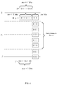
- the intermediate precision has xw extras bits or guard bits compared to the output precision. For example, as shown in FIG. 4 , if xw is equal to 3 and the calculated result y c is "1 0 1 1 0 1 1 1 1 1 1".
- the half way number is generated by setting the half way number y h to the calculated result y c ("1 0 1 1 0 1 1 111 ) and then setting the first guard bit to "1" and setting the remainder of the guard bits to "0" so that the final half way number y h is "1 0 1 1 0 1 1 1 1 0 0 ".
- the first mw +1 bits of the half way number are set to the first mw + 1 bits of the calculated result y c
- the first guard bit is set to "1”
- the remaining guard bits are set to "0".
- method 300 proceeds to block 308.
- equation (11) comprises a single multiplication and a single addition/subtraction it can be accurately evaluated using an FMA.
- the half way number y h is half way between two representable numbers in the output precision (mw + 1 bits of precision) the half way number y h requires mw + 2 bits of precision to be accurately represented. The square of the half way number, will thus require 2 * (mw + 2) bits to be accurately represented based on the rules of multiplication. If r is calculated in the output precision (mw +1) then the rounding error appears after mw + 1 bits therefore there are at most mw + 3 bits of error, e. Accordingly the error e can be accurately represented in the intermediate precision if there are at least two extra bits or guard bits for the intermediate precision (i.e. xm ⁇ 2).
- equation (16) can be generated from the left-hand side of inequality (15) by replacing (r ⁇ a - 1) with dh.
- an FMA can accurately determine whether d is less than (negative) or greater than (positive) zero. This determination can then be used to decide whether to round the calculated result up or down.
- the FMA can also be configured to specifically identify and indicate when d is exactly equal to zero.
- d is negative then the half way number y h is less than the infinitely precise result y thus the result y c in the intermediate precision should be rounded up; and if d is positive then the half way number y h is greater than the infinitely precise result y and thus the result y c in the intermediate precision should be rounded down. If d is equal to zero then it may be rounded up or down according to a tie-break rule. For example, as described above, when RTE rounding is used ties are rounded up if that will produce an even result (i.e. the last bit of the result is zero) otherwise ties are rounded down.
- the method 300 proceeds to bock 314 where an indication of whether the infinitely precise result is greater than, less than or equal to the half way number is output based on the value of d .
- an indication of whether the infinitely precise result is greater than, less than or equal to the half way number is output based on the value of d .
- the sign of d may be output to indicate whether the infinitely precise result y is greater than or less than the half way number y h .
- the method 300 described with reference to FIG. 3 allows a reciprocal square root result to be accurately rounded in manner that uses minimal and existing hardware (i.e. hardware that likely already forms part of a reciprocal square root circuit or logic unit, such as an FMA).
- the method 300 may also produce a faster result than other methods that assume the first delta dh has an error component that needs to be taken into account. For example, such methods may require additional (potentially hundreds of) passes through an FMA to correctly determine whether to round up or round down.
- the method 300 also allows reciprocal square root results to be accurately rounded with very few extra or guard bits.
- a determination may be made as to whether the calculated result y c in the intermediate precision is within a predetermined range of the half way number y h (i.e. it is "close” to the half way number). If is determined that the calculated result y c in the intermediate precision is within the predetermined range of the half way number y h then the method 300 may proceed to blocks 304 to 314 to determine whether the infinitely precise result y is greater than, less than or equal to the half way number y h .
- the calculated result y c in the intermediate precision may be rounded up or down in the output precision based on the determination of whether the infinitely precise result y is greater than, less than or equal to the half way number y h . If, however, it determined that the calculated result y c in the intermediate precision is not within the predetermined range of the half way number y h (i.e. it is "far" from the half way number y h ) then the method 300 may end and the calculated result y c may be directly rounded to the nearest representable number in the output precision.
- the determination of whether the calculated result y c in the intermediate precision is within a predetermined range of the half way number y h may be based on the additional or guard bits of the calculated result y c .
- the output result has a precision of mw +1 bits and the calculated result y c has a higher precision with xm extra bits which may be referred to as the guard bits. For example, if, as shown in FIG. 4 , mw is equal to seven and xm is equal to three, the representable output numbers (e.g. j and k) will have eight bits of precision and the calculated result y c will have eleven bits of precision.
- each pair of consecutive representable numbers in the output precision (e.g. mw +1 bits of precision) there will be 2 xm - 1 possible numbers in the intermediate precision that lie between them.
- Each of the numbers in the intermediate precision that lie between the two representable numbers in the lower output precision has the same first mw +1 bits (which is equal to the lower of the two representable numbers in the lower output precision); however the extra/guard bits differ.
- a calculated result will be determined to be within a predetermined range of the half way number y h if the extra bits/guard bits comprise the patterns 010 to 110 inclusive as shown in FIG. 4 .
- the half way number y h is roughly equal to the reciprocal square root of input floating point number a as shown in equation (17): y h ⁇ 1 a
- Equation (21) can then be written in terms of equation (18) (i.e. y h is replaced with 1 a 1 + ⁇ ) to produce equation (22), which can be simplified to equation (23)) as the a' s cancel out, and then expanded to equations (24), (25), and (26):
- inequality (28) is re-written in terms of inequality (29) (i.e.
- FIG. 7 illustrates a first example system 700 for determining whether the infinitely precise result y of a reciprocal square root calculation preformed on a floating point number a is greater than or less than a half way number y h indicated by the calculated result y c in an intermediate precision in accordance with the method 300 of FIG. 3 .
- the computer system 700 receives as inputs the input floating point number a in the output precision and the calculated result y c in the intermediate precision and outputs an indication of whether the infinitely precise result y of the reciprocal square root calculation is greater than, less than, or equal to the half way number y h .
- the output indication can then be used to determine whether the calculated result y c in the intermediate precision should be rounded up or rounded down in a lower output precision.
- the system 700 comprises half way number generation logic 702, squaring logic 704, three multiply-add logic 706, 708, and 710 and output logic 712.
- the half way number generation logic 702 receives the calculated result y c in the intermediate precision (i.e. it has mw + 1 + xm bits of precision) and generates and outputs a half way number y h based on the calculated result.
- the half way number y h is the number in the intermediate precision (i.e. with mw + 1 + xm bits of precision) that lies halfway between the closest representable number in the output precision below the calculated result and the closest representable number in the output precision above the calculated result.
- the half way number y h may be generated from the calculated result y c by setting the extra bits or guard bits of y h to "1 0 0 .". For example if the calculated result y c is equal to "1 0 1 1 0 1 1 1 1 " and has three guard bits (i.e. the last three bits are extra bits) then the half way number y h is equal to "1 0 1 1 0 1 1 1 1 0 0 ".
- system 700 may also comprise a logic unit (not shown) that determines whether the calculated result is representable in the lower output precision (indicating it is a correctly rounded output result) and only forwards the calculated result to the squaring logic 702 if it is determined that the calculated result is not representable in the lower output precision.
- the logic unit may be configured to determine that the calculated result is representable in the lower output precision if the extra or guard bits are zero.
- the squaring logic 704 is coupled to the output of the half way number generation logic 702 to receive the half way number y h .
- the squaring logic 704 is configured to calculate and output the square of the half way number y h , referred to as r .
- the squaring logic 704 may be configured to evaluate equation (10) described above.
- the calculated square of the half way number r is represented in the output precision (i.e. with mw +1 bits or precision).
- the squaring logic 704 may be implemented using a fused-multiply add component that is configured to calculate, for example, y h * y h + 0 or y h *y h - 0 .
- the first multiply-add logic 706 is coupled to the output of the half way number generation logic 702 and the output of the squaring logic 704 to receive the half way number y h and the calculated square of the half way number r .
- the first multiply-add logic 706 is configured to calculate and output the error in the calculated square r , referred to as e .
- the first multiply-add logic 706 may be configured to calculate the error in the calculated square r by calculating, in one step, the square of the half way number y h less the calculated square of the half way number r .
- the first multiply-add logic 706 may be configured to evaluate equation (11) described above.
- the first multiply-add logic 706 may be configured to invert the output of the squaring logic (i.e. invert r) prior to performing the calculation. In other cases there may be inverter or negate logic between the output of the squaring logic 704 and the input to the first multiply-add logic 706. As shown in FIG. 7 the first multiply-add logic 706 may be implemented as a fused multiply-add component.
- the second multiply-add logic 708 is coupled to the floating point input a and the output of the squaring logic 704 to receive the floating point input a and the calculated square of the half way number r.
- the second multiply-add logic 708 is configured to calculate and output r x a - 1, referred to as dh or the first delta value.
- the second multiply-add logic 708 may be configured to evaluate equation (12) described above. In some cases dh or the first delta value is represented in the intermediate precision (i.e. using mw + 1 + xm mantissa bits).
- the second multiply-add logic 708 may be implemented as a fused multiply-add component.
- the third multiply-add logic 710 is coupled to the floating point input a, the output of the first multiply-add logic 706, and the output of the second multiply-add logic 708, to receive the floating point input a, the calculated error e in the calculated square of the half way number, and the calculated dh or first delta value.
- the third multiply-add logic 710 is configured to calculate and output dh + e ⁇ a, referred to as d or the second delta value, in a single rounding step.
- the third multiply-add logic 710 may be configured to evaluate equation (16) described above.
- the third multiply-add logic 710 may be implemented as a fused multiply-add component.
- the sign of d correctly or accurately indicates whether the infinitely precise result y of the reciprocal square root operation is greater than or less than the half way number y h .
- round to nearest rounding if d is negative then the half way number y h is less than the infinitely precise result y and the result y c in the intermediate precision should be rounded up; and if d is positive then the half way number y h is greater than the infinitely precise result y and the result y c in the intermediate precision should be rounded down.
- the output logic 712 is coupled to the output of the third multiply-add logic 710 to receive d .
- the output logic 712 is configured to output an indication of whether the infinitely precise result is above, below or equal to the half way number based on the received d .
- the output logic 712 may be configured to output a "1" when d or the second delta value is positive and output a "0" when d or the second delta value is negative.
- the output logic 712 may simply output the sign bit, s , of the input d .
- the system 700 may be implemented in hardware (e.g. as fixed function circuitry in a computer processor); software (e.g. software to be executed on a processor); or a combination of hardware and software. Implementing the system 700 completely in hardware may allow for faster computation.
- FIG. 8 illustrates a second example system 800 for determining whether the infinitely precise result y of a reciprocal square root calculation preformed on a floating point number a is greater than, less than, or equal to a half way number y h indicated by the calculated result y c in an intermediate precision in accordance with the method 300 of FIG. 3 .
- the computer system 800 like the computer system 700 of FIG. 7 , receives as inputs the input floating point number a in the output precision and the calculated result y c in the intermediate precision and outputs an indication of whether the infinitely precise result y of the reciprocal square root calculation is greater than, less than, or equal to the half way number y h .
- the output indication can then be used to determine whether the calculated result y c in the intermediate precision should be rounded up or rounded down in a lower output precision.
- the system 800 comprises half way number generation logic 802, and output logic 812 which operate in the same manner as the half way number generation logic 702 and the output logic 712 of FIG. 7 to generate the half way number and output an indication of whether the infinitely precise result is above, below or equal to the half way number respectively.
- the system 800 of FIG. 8 comprises a single multiply-add logic 820 that is configured to perform the functions of the multiply-add logic 706, 708, 710 and squaring logic 704 of FIG. 7 over a number of system cycles (e.g. clock cycles).
- the multiply-add logic 820 may calculate and output the square of the half way number y h , referred to as r.
- the multiply-add logic 820 may be configured to evaluate equation (10) described above in a first clock cycle.
- the multiply-add logic 820 may calculate and output the error in the calculated square r , referred to as e .
- the multiply-add logic 820 may be configured to calculate the error in the calculated square r by calculating, in one step, the square of the half way number y h less the calculated square of the half way number r .
- the multiply-add logic 820 may be configured to evaluate equation (11) described above in a second clock cycle.
- the multiply-add logic 820 may calculate and output r ⁇ a - 1, referred to as dh or the first delta value.
- the multiply-add logic 820 may be configured to evaluate equation (12) described above in a third clock cycle.
- the multiply-add logic 820 may calculate and output dh + e ⁇ a, referred to as d or the second delta value, in a single rounding step.
- the multiply-add logic 810 may be configured to evaluate equation (16) described above in a fourth clock cycle.
- the system 800 may also comprise control logic 822 that is configured to provide the appropriate inputs to the FMA in each cycle (e.g. clock cycle).
- control logic 822 may be configured to receive as inputs the input floating point number a, the half way number y h , and the output(s) of the FMA 820; and select, from these inputs, the appropriate inputs to the FMA 820 for each cycle (e.g. clock cycle).
- control logic 822 may be configured to provide the half way number y h as the first two inputs to the FMA 820 and zero as the third input to the FMA 820.
- control logic 822 may be configured to provide the half-way number y h as the first two inputs of the FMA 820 and the negative square of the half way number r as the third input of the FMA 820.
- control logic 822 may be configured to provide the square of the half way number r and the input floating point number a as the first two inputs of the FMA 820 and -1 as the third input to the FMA 820.
- control logic 822 may be configured to provide the error in the square e and the input floating point number a as the first two inputs to the FMA 820 and the first delta value dh as the third input to the FMA 820.
- control logic 822 may be implemented in hardware or software.
- control logic 822 may be implemented as one or more multiplexers.
- the system 800 may also comprise one or more storage units 824 for storing the output of the FMA 820 in a particular cycle (e.g. clock cycle) for use in a later cycle (e.g. clock cycle).
- the one or more storage units 824 may be configured to store the outputs r and e for use in a later calculation (e.g. in a later cycle).
- the one or more storage units 824 may be connected or otherwise coupled to the output of the FMA 820 to receive the output; and connected or otherwise coupled to an input of the control logic 822 to provide the stored output as an input to the control logic 822.
- the one or more storage units 824 may be implemented using any storage mechanism suitable for storing a binary number such as, but not limited to, one or more registers, or one or more memory units.
- the system 800 may be implemented in hardware (e.g. as fixed function circuitry in a computer processor); software (e.g. software to be executed on a processor); or a combination of hardware and software. Implementing the system 800 completely in hardware may allow for faster computation.
- the system 800 may provide a significant improvement over system 700 in terms of hardware and space required to implement the system since only a single multiply-add component (e.g. FMA) is used to perform all of the calculations.
- a single multiply-add component e.g. FMA
- systems 700 and 800 are examples only, and the method 300 described above with reference to FIG. 3 for determining whether the infinitely precise result y of a floating point reciprocal square root operation is above or below a half way number, may be implemented in another manner.
- the system may not comprise output logic 712 or 812 and may alternatively be configured to directly output d generated by the third multiply-add logic 710 or the single multiply-add component 820.
- the system 900 comprises reciprocal square root logic 902, an above or below half way number system 904 implementing the method 300 of FIG. 3 (e.g. system 700 or 800), and rounding logic 906.
- the reciprocal square root logic 902 is configured to receive a floating point number a in the output precision.
- the reciprocal square root logic 902 is configured to calculate and output the reciprocal square root of the input floating point number a, in an intermediate precision (e.g. mw + 1 + xm bits of precision) which is greater than the output precision (e.g. mw +1 bits of precision).
- the calculated result y c in the intermediate precision has a relative error of strictly less than 2 -( mw +1) compared to the infinitely precise result y.
- the reciprocal square root logic 902 may be configured to use any suitable method for calculating the reciprocal square root of a with the required accuracy.
- the reciprocal square root logic 902 may be configured to calculate the reciprocal square root of a using a converging approximation technique, such as, but not limited to, a Newton-Raphson technique or a Goldschmidt technique.
- the above or below half way number system 904 (e.g. system 700 or 800) is coupled to the input floating point number a and the output of the reciprocal square root logic 902 to receive the input floating point number a in the output precision and the calculated result y c in the intermediate precision.
- the above or below half way number system 904 is configured to generate, from the input floating point number a and the calculated result y c in the intermediate precision, an accurate indication (e.g. sign ( d )) of whether the infinitely precise result y of the reciprocal square root is greater than, less than or equal to the half way number y h indicated by the calculated result y c in the intermediate precision.
- the rounding logic 906 is coupled to the output of the reciprocal square root logic 902 and the output of the above or below half way number system 904 to receive the calculated result y c in the intermediate precision and the indication (e.g. sign (d)) indicating whether the infinitely precise result is greater than, less than or equal to the half way number y h .
- the rounding logic 906 is configured to correctly round the calculated result y c in the intermediate precision to the output precision based on the indication (e.g. sign (d)) and the specific rounding technique used.
- the rounding logic 906 may be configured to round the calculated result up to the first representable number in the output precision that is greater than the calculated result y c ; and if the output of the above or below half way number system 904 (e.g. sign (d)) indicates the infinitely precise result is less than the half way number y h then the rounding logic 906 may be configured to round the calculated result y c down to the first representable number in the output precision that is less than the calculated result y c .
- a tie-break technique is used. For example, as described above, if the RTE (round to nearest, tie to even) rounding method or technique is used then the calculated result is rounded up if that will produce an even result (i.e. the last bit of the result is 0) otherwise the calculated result is rounded down.
- rounding the calculated result y c down may comprise setting the output result y r to the first mw bits of the calculated result y c
- rounding the calculated result y c up may comprise setting the output result to the first mw bits of the calculated result y c and adding 1. For example, if, as shown in FIG.
- the calculated result y c in the intermediate precision is 11 bits long with 3 guard bits and is equal to "1 0 1 1 0 1 1 1 1 1”
- rounding the calculated result y c up to k comprises selecting the first 8 bits (" 1 0 1 1 0 1 1 ") and adding 1 which results in "1 0 1 1 1 0 0 0"
- rounding the calculated result y c down to j comprises selecting the first 8 bits (" 1 0 1 1 0 1 1 ").
- the system 900 may be implemented in hardware (e.g. as fixed function circuitry in a computer processor); software (e.g. software to be executed on a processor); or a combination of hardware and software. Implementing the system 900 completely in hardware may allow for faster computation.
- computer system 900 is an example of a system for determining an accurately rounded result of a reciprocal square root operation using the method 300 described above with reference to FIG. 3 to determine whether the infinitely precise result y of a floating point reciprocal square root operation is above or below a half way number, and other systems using the principles and techniques described herein may be implemented in a different manner.
- the system may also comprise decision logic (not shown) which is configured to receive the calculated result y c and determine whether the calculated result y c in the intermediate precision is far enough away from the half way number y h that it can be directly rounded without first determining whether the infinitely precise result is above or below the halfway number y h .
- the decision logic may be configured to determine the calculated result y c is "close" to the half way number y h when the guard bits of the calculated result y c have a specified pattern (e.g. "0 1 0 ... " to " 0 1 0 " inclusive).
- the output of the decision logic may then be provided to the rounding logic 906 to determine whether the calculated result can be rounded directly without the output from the above or below half way number system 904.
- a "directed rounding" technique or mode which rounds in a specific direction (e.g. towards zero, away from zero, towards negative infinity, towards positive infinity) instead of simply to the closest representable number as in a "round to nearest" rounding technique or mode, then instead of determining whether the infinitely precise result is above or below the half way number it is desirable to know whether the infinitely precise result is above, below or equal to the closest representable number in the lower output precision to the calculated result. Accordingly, in these cases instead of identifying the half way number y h from the calculated result y c , the closest representable number y a in the lower output precision is identified from the calculated result y c .
- the calculated result y c will lie between two half way numbers.
- a half way number is a number in the intermediate precision that lies half way between two consecutive representable numbers in the lower output precision.
- the closest representable number will be the representable number in the lower output precision that lies between the two half way numbers on either side of the calculated result y c .
- method 300 of FIG. 3 can be used to determine if the infinitely precise result y is above, below or equal to the closest representable number y a .
- the calculated result y c is considered sufficiently accurate when the calculated result y c is guaranteed to be within 2 mw +1 o f the infinitely precise result y.
- next closest representable number y b is the next representable number from the closest representable number y a in the direction of zero; and for round towards positive infinity, the next closest representable number y b is the next representable number from the closest representable number y a in the direction of positive infinity.
- method 300 of FIG. 3 can be used to determine if the infinitely precise result is above, below or equal to the closest representable number y a by replacing the half way number y h with the closest representable number y a . Based on this determination the calculated result y c in the intermediate precision can be correctly rounded according to the specific rounding technique or mode.
- the calculated result may be rounded to the next closest representable number y b .
- the infinitely precise result y may be rounded to the closest representable number y a .
- the methods (e.g. method 300) and systems (e.g. systems 700 and 800) described herein can be used to identify whether the infinitely precise result y of a reciprocal square root calculation is above, below, or equal to a particular number t so long as the particular number t is sufficiently close to the infinitely precise result y of the reciprocal square root calculation.
- the particular number t is considered sufficiently close if inequality (30) is satisfied, where ⁇ is the error between the particular number t and the infinitely precise result y.
- the particular number t is the half way number y h indicated by the calculated result y c .
- the particular number t is the closest representable number y a indicated by the calculated result y c .
- the particular number t may be another number.
- FIG. 10 illustrates various components of an exemplary computing-based device 1000 which may be implemented as any form of a computing and/or electronic device, and in which embodiments of the methods and systems described above may be implemented.
- Computing-based device 1000 comprises one or more processors 1002 which may be microprocessors, controllers or any other suitable type of processors for processing computer executable instructions to control the operation of the device in order to determine whether the infinitely precise result of a reciprocal square root operation is below or above a half-way number.
- the processors 1002 may include one or more fixed function blocks (also referred to as accelerators) which implement a part of the method of FIG. 3 in hardware (rather than software or firmware).
- Platform software comprising an operating system 1004 or any other suitable platform software may be provided at the computing-based device to enable application software 1006 to be executed on the device.
- Computer-readable media may include, for example, computer storage media such as memory 1008 and communications media.
- Computer storage media i.e. non-transitory machine readable media
- memory 1008 includes volatile and non-volatile, removable and non-removable media implemented in any method or technology for storage of information such as computer readable instructions, data structures, program modules or other data.
- Computer storage media includes, but is not limited to, RAM, ROM, EPROM, EEPROM, flash memory or other memory technology, CD-ROM, digital versatile disks (DVD) or other optical storage, magnetic cassettes, magnetic tape, magnetic disk storage or other magnetic storage devices, or any other non-transmission medium that can be used to store information for access by a computing device.
- communication media may embody computer readable instructions, data structures, program modules, or other data in a modulated data signal, such as a carrier wave, or other transport mechanism.
- computer storage media does not include communication media.
- the computer storage media i.e. non-transitory machine readable media, e.g. memory 1008
- the storage may be distributed or located remotely and accessed via a network or other communication link (e.g. using communication interface 1010).
- the computing-based device 1000 also comprises an input/output controller 1012 arranged to output display information to a display device 1014 which may be separate from or integral to the computing-based device 1000.
- the display information may provide a graphical user interface.
- the input/output controller 1012 is also arranged to receive and process input from one or more devices, such as a user input device 1016 (e.g. a mouse or a keyboard).
- the display device 1014 may also act as the user input device 1016 if it is a touch sensitive display device.
- the input/output controller 1012 may also output data to devices other than the display device, e.g. a locally connected printing device (not shown in FIG. 10 ).
- the term 'processor' and 'computer' are used herein to refer to any device, or portion thereof, with processing capability such that it can execute instructions.
- the term 'processor' may, for example, include central processing units (CPUs), graphics processing units (GPUs or VPUs), physics processing units (PPUs), radio processing units (RPUs), digital signal processors (DSPs), general purpose processors (e.g. a general purpose GPU), microprocessors, any processing unit which is designed to accelerate tasks outside of a CPU, etc.
- CPUs central processing units
- GPUs or VPUs graphics processing units
- PPUs physics processing units
- RPUs radio processing units
- DSPs digital signal processors
- general purpose processors e.g. a general purpose GPU
- microprocessors any processing unit which is designed to accelerate tasks outside of a CPU, etc.
- a remote computer may store an example of the process described as software.
- a local or terminal computer may access the remote computer and download a part or all of the software to run the program.
- the local computer may download pieces of the software as needed, or execute some software instructions at the local terminal and some at the remote computer (or computer network).
- a dedicated circuit such as a DSP, programmable logic array, or the like.
- the methods described herein may be performed by a computer configured with software in machine readable form stored on a tangible storage medium e.g. in the form of a computer program comprising computer readable program code for configuring a computer to perform the constituent portions of described methods or in the form of a computer program comprising computer program code means adapted to perform all the steps of any of the methods described herein when the program is run on a computer and where the computer program may be embodied on a computer readable storage medium.
- tangible (or non-transitory) storage media include disks, thumb drives, memory cards etc. and do not include propagated signals.
- the software can be suitable for execution on a parallel processor or a serial processor such that the method steps may be carried out in any suitable order, or simultaneously.
- the hardware components described herein may be generated by a non-transitory computer readable storage medium having encoded thereon computer readable program code.
- HDL hardware description language
- a computer system may be configured to generate a representation of a digital circuit from definitions of circuit elements and data defining rules for combining those circuit elements, wherein a non-transitory computer readable storage medium may have stored thereon processor executable instructions that when executed at such a computer system, cause the computer system to generate a processing unit as described herein.
- a non-transitory computer readable storage medium may have stored thereon computer readable instructions that, when processed at a computer system for generating a manifestation of an integrated circuit, cause the computer system to generate a manifestation of a processor as described in the examples herein or to generate a manifestation of a processor configured to perform a method as described in the examples herein.
- the manifestation of a processor could be the processor itself, or a representation of the processor (e.g. a mask) which can be used to generate the processor.
- Non-transitory media can be volatile or non-volatile.
- volatile non-transitory media include semiconductor-based memory, such as SRAM or DRAM.
- technologies that can be used to implement non-volatile memory include optical and magnetic memory technologies, flash memory, phase change memory, resistive RAM.
- logic refers to structure that performs a function or functions.
- An example of logic includes circuitry that is arranged to perform those function(s).
- circuitry may include transistors and/or other hardware elements available in a manufacturing process.
- transistors and/or other elements may be used to form circuitry or structures that implement and/or contain memory, such as registers, flip flops, or latches, logical operators, such as Boolean operations, mathematical operators, such as adders, multipliers, or shifters, and interconnect, by way of example.
- Such elements may be provided as custom circuits or standard cell libraries, macros, or at other levels of abstraction. Such elements may be interconnected in a specific arrangement.
- Logic may include circuitry that is fixed function and circuitry can be programmed to perform a function or functions; such programming may be provided from a firmware or software update or control mechanism.
- Logic identified to perform one function may also include logic that implements a constituent function or sub-process.
- hardware logic has circuitry that implements a fixed function operation, or operations, state machine or process.
- any reference to 'an' item refers to one or more of those items.
- the term 'comprising' is used herein to mean including the method blocks or elements identified, but that such blocks or elements do not comprise an exclusive list and an apparatus may contain additional blocks or elements and a method may contain additional operations or elements. Furthermore, the blocks, elements and operations are themselves not impliedly closed.
Landscapes
- Engineering & Computer Science (AREA)
- Physics & Mathematics (AREA)
- General Physics & Mathematics (AREA)
- Theoretical Computer Science (AREA)
- Computational Mathematics (AREA)
- Mathematical Analysis (AREA)
- Pure & Applied Mathematics (AREA)
- Computing Systems (AREA)
- Mathematical Optimization (AREA)
- General Engineering & Computer Science (AREA)
- Nonlinear Science (AREA)
- Complex Calculations (AREA)
Applications Claiming Priority (1)
| Application Number | Priority Date | Filing Date | Title |
|---|---|---|---|
| GB1518478.1A GB2543511B (en) | 2015-10-19 | 2015-10-19 | Rounding reciprocal square root results |
Publications (2)
| Publication Number | Publication Date |
|---|---|
| EP3159788A1 true EP3159788A1 (fr) | 2017-04-26 |
| EP3159788B1 EP3159788B1 (fr) | 2018-08-29 |
Family
ID=55131257
Family Applications (1)
| Application Number | Title | Priority Date | Filing Date |
|---|---|---|---|
| EP16194577.9A Active EP3159788B1 (fr) | 2015-10-19 | 2016-10-19 | Arrondissement de résultats de racine carré réciproque |
Country Status (4)
| Country | Link |
|---|---|
| US (2) | US11294625B2 (fr) |
| EP (1) | EP3159788B1 (fr) |
| CN (1) | CN107038014B (fr) |
| GB (1) | GB2543511B (fr) |
Families Citing this family (5)
| Publication number | Priority date | Publication date | Assignee | Title |
|---|---|---|---|---|
| US10592208B2 (en) * | 2018-05-07 | 2020-03-17 | International Business Machines Corporation | Very low precision floating point representation for deep learning acceleration |
| US10963219B2 (en) | 2019-02-06 | 2021-03-30 | International Business Machines Corporation | Hybrid floating point representation for deep learning acceleration |
| GB2582146B (en) * | 2019-03-11 | 2021-08-18 | Graphcore Ltd | Execution Unit for Evaluating Functions Using Newton Raphson Iterations |
| GB2581543B (en) | 2019-07-19 | 2021-03-03 | Imagination Tech Ltd | Apparatus and method for processing floating-point numbers |
| GB2581542A (en) | 2019-07-19 | 2020-08-26 | Imagination Tech Ltd | Apparatus and method for processing floating-point numbers |
Citations (1)
| Publication number | Priority date | Publication date | Assignee | Title |
|---|---|---|---|---|
| US20050027772A1 (en) * | 2003-07-31 | 2005-02-03 | Ibm Corporation | Increased precision in the computation of a reciprocal square root |
Family Cites Families (15)
| Publication number | Priority date | Publication date | Assignee | Title |
|---|---|---|---|---|
| US27772A (en) * | 1860-04-10 | Btjrglak-alabm | ||
| US5671170A (en) * | 1993-05-05 | 1997-09-23 | Hewlett-Packard Company | Method and apparatus for correctly rounding results of division and square root computations |
| US6643765B1 (en) * | 1995-08-16 | 2003-11-04 | Microunity Systems Engineering, Inc. | Programmable processor with group floating point operations |
| US6163791A (en) * | 1998-02-02 | 2000-12-19 | International Business Machines Corporation | High accuracy estimates of elementary functions |
| US6625632B1 (en) * | 2000-03-24 | 2003-09-23 | Mercury Computer Systems, Inc. | Method and apparatus for square root generation using bit manipulation and instruction interleaving |
| US6996596B1 (en) * | 2000-05-23 | 2006-02-07 | Mips Technologies, Inc. | Floating-point processor with operating mode having improved accuracy and high performance |
| US7730117B2 (en) * | 2005-02-09 | 2010-06-01 | International Business Machines Corporation | System and method for a floating point unit with feedback prior to normalization and rounding |
| US20060271615A1 (en) * | 2005-05-27 | 2006-11-30 | Shearer James B | Method to compute an approximation to the reciprocal of the square root of a floating point number in IEEE format |
| US8745118B2 (en) * | 2008-02-25 | 2014-06-03 | International Business Machines Corporation | Verifying floating point square root operation results |
| US20140067894A1 (en) * | 2012-08-30 | 2014-03-06 | Qualcomm Incorporated | Operations for efficient floating point computations |
| US9483232B2 (en) * | 2014-03-07 | 2016-11-01 | Arm Limited | Data processing apparatus and method for multiplying floating point operands |
| CN104133656A (zh) * | 2014-07-25 | 2014-11-05 | 国家电网公司 | 一种尾码采用移位和减法运算的浮点数除法器及运算方法 |
| US9612800B2 (en) * | 2014-08-05 | 2017-04-04 | Imagination Technologies Limited | Implementing a square root operation in a computer system |
| CN104598197B (zh) * | 2015-01-26 | 2017-05-31 | 中国科学院自动化研究所 | 一种浮点倒数和/或平方根倒数运算方法及其装置 |
| CN104636114B (zh) * | 2015-02-12 | 2018-05-15 | 北京思朗科技有限责任公司 | 一种浮点数乘法的舍入方法及装置 |
-
2015
- 2015-10-19 GB GB1518478.1A patent/GB2543511B/en active Active
-
2016
- 2016-10-14 US US15/293,541 patent/US11294625B2/en active Active
- 2016-10-19 CN CN201610911752.2A patent/CN107038014B/zh active Active
- 2016-10-19 EP EP16194577.9A patent/EP3159788B1/fr active Active
-
2021
- 2021-11-30 US US17/538,676 patent/US11853716B2/en active Active
Patent Citations (1)
| Publication number | Priority date | Publication date | Assignee | Title |
|---|---|---|---|---|
| US20050027772A1 (en) * | 2003-07-31 | 2005-02-03 | Ibm Corporation | Increased precision in the computation of a reciprocal square root |
Non-Patent Citations (4)
| Title |
|---|
| "IA-64 and Elementary Functions, Chapter 9 Square Root", 1 January 2000, PRENTICE-HALL, ISBN: 978-0-13-018348-4, article PETER MARKSTEIN: "IA-64 and Elementary Functions, Chapter 9 Square Root", XP055348475 * |
| CLAUDE-PIERRE JEANNEROD ET AL: "Optimizing correctly-rounded reciprocal square roots for embedded VLIW cores", SIGNALS, SYSTEMS AND COMPUTERS, 2009 CONFERENCE RECORD OF THE FORTY-THIRD ASILOMAR CONFERENCE ON, IEEE, PISCATAWAY, NJ, USA, 1 November 2009 (2009-11-01), pages 731 - 735, XP031679490, ISBN: 978-1-4244-5825-7 * |
| ERCEGOVAC M D ET AL: "RECIPROCATION, SQUARE ROOT, INVERSE SQUARE ROOT, AND SOME ELEMENTARY FUNCTIONS USING SMALL MULTIPLIERS", IEEE TRANSACTIONS ON COMPUTERS, IEEE SERVICE CENTER, LOS ALAMITOS, CA, US, vol. 49, no. 7, 1 July 2000 (2000-07-01), pages 628 - 636, XP000970032, ISSN: 0018-9340, DOI: 10.1109/12.863031 * |
| IORDACHE C ET AL: "ON INFINITELY PRECISE ROUNDING FOR DIVISION, SQUARE ROOT, RECIPROCAL AND SQUARE ROOT RECIPROCAL", PROCEEDINGS 14TH IEEE SYMPOSIUM ON COMPUTER ARITHMETIC. ADELAIDE, AU, APRIL 14 - 16, 1999; [IEEE SYMPOSIUM ON COMPUTER ARITHMETIC], LOS ALAMITOS, CA : IEEE COMP. SOC. PRESS, US, 14 April 1999 (1999-04-14), pages 233 - 240, XP000876427, ISBN: 978-0-7803-5609-2, DOI: 10.1109/ARITH.1999.762849 * |
Also Published As
| Publication number | Publication date |
|---|---|
| CN107038014B (zh) | 2022-07-01 |
| US11294625B2 (en) | 2022-04-05 |
| US11853716B2 (en) | 2023-12-26 |
| CN107038014A (zh) | 2017-08-11 |
| GB201518478D0 (en) | 2015-12-02 |
| EP3159788B1 (fr) | 2018-08-29 |
| US20170109134A1 (en) | 2017-04-20 |
| GB2543511B (en) | 2018-07-25 |
| GB2543511A (en) | 2017-04-26 |
| US20220091819A1 (en) | 2022-03-24 |
Similar Documents
| Publication | Publication Date | Title |
|---|---|---|
| US11853716B2 (en) | System and method for rounding reciprocal square root results of input floating point numbers | |
| JP3541066B2 (ja) | コンピュータにおいて除算および平方根計算を実施するための方法および装置 | |
| KR102358013B1 (ko) | 3-경로 단일 곱셈-누산기 설계에서 고속 근경로 증분합 | |
| US11809795B2 (en) | Implementing fixed-point polynomials in hardware logic | |
| CN106250098A (zh) | 用于在执行浮点运算时控制舍入的装置及方法 | |
| US20210182028A1 (en) | Trailing or Leading Digit Anticipator | |
| EP3236348B1 (fr) | Évaluation de polynômes dans une logique matérielle | |
| Chung | Provably correct posit arithmetic with fixed-point big integer | |
| US9959091B2 (en) | Evaluation of polynomials with floating-point components | |
| US10416960B2 (en) | Check procedure for floating point operations | |
| Nguyen et al. | Clarifications and optimizations on rounding for IEEE-compliant floating-point multiplication | |
| US20240134607A1 (en) | Hardware to perform squaring | |
| US9342270B2 (en) | Conversion of a normalized n-bit value into a normalized m-bit value | |
| US20230147929A1 (en) | Exact versus inexact decimal floating-point numbers and computation system | |
| US9875083B2 (en) | Performing a comparison computation in a computer system | |
| GB2622034A (en) | Efficient floating point squarer |
Legal Events
| Date | Code | Title | Description |
|---|---|---|---|
| PUAI | Public reference made under article 153(3) epc to a published international application that has entered the european phase |
Free format text: ORIGINAL CODE: 0009012 |
|
| AK | Designated contracting states |
Kind code of ref document: A1 Designated state(s): AL AT BE BG CH CY CZ DE DK EE ES FI FR GB GR HR HU IE IS IT LI LT LU LV MC MK MT NL NO PL PT RO RS SE SI SK SM TR |
|
| AX | Request for extension of the european patent |
Extension state: BA ME |
|
| 17P | Request for examination filed |
Effective date: 20171013 |
|
| RBV | Designated contracting states (corrected) |
Designated state(s): AL AT BE BG CH CY CZ DE DK EE ES FI FR GB GR HR HU IE IS IT LI LT LU LV MC MK MT NL NO PL PT RO RS SE SI SK SM TR |
|
| GRAP | Despatch of communication of intention to grant a patent |
Free format text: ORIGINAL CODE: EPIDOSNIGR1 |
|
| RIC1 | Information provided on ipc code assigned before grant |
Ipc: G06F 7/499 20060101AFI20180228BHEP Ipc: G06F 7/552 20060101ALI20180228BHEP |
|
| INTG | Intention to grant announced |
Effective date: 20180314 |
|
| GRAS | Grant fee paid |
Free format text: ORIGINAL CODE: EPIDOSNIGR3 |
|
| GRAA | (expected) grant |
Free format text: ORIGINAL CODE: 0009210 |
|
| RBV | Designated contracting states (corrected) |
Designated state(s): AL AT BE BG CH CY CZ DE DK EE ES FI FR GR HR HU IE IS IT LI LT LU LV MC MK MT NL NO PL PT RO RS SE SI SK SM TR |
|
| AK | Designated contracting states |
Kind code of ref document: B1 Designated state(s): AL AT BE BG CH CY CZ DE DK EE ES FI FR GR HR HU IE IS IT LI LT LU LV MC MK MT NL NO PL PT RO RS SE SI SK SM TR |
|
| REG | Reference to a national code |
Ref country code: CH Ref legal event code: EP |
|
| REG | Reference to a national code |
Ref country code: AT Ref legal event code: REF Ref document number: 1035923 Country of ref document: AT Kind code of ref document: T Effective date: 20180915 |
|
| REG | Reference to a national code |
Ref country code: IE Ref legal event code: FG4D |
|
| REG | Reference to a national code |
Ref country code: DE Ref legal event code: R096 Ref document number: 602016005141 Country of ref document: DE |
|
| REG | Reference to a national code |
Ref country code: FR Ref legal event code: PLFP Year of fee payment: 3 |
|
| REG | Reference to a national code |
Ref country code: NL Ref legal event code: MP Effective date: 20180829 |
|
| REG | Reference to a national code |
Ref country code: LT Ref legal event code: MG4D |
|
| PG25 | Lapsed in a contracting state [announced via postgrant information from national office to epo] |
Ref country code: FI Free format text: LAPSE BECAUSE OF FAILURE TO SUBMIT A TRANSLATION OF THE DESCRIPTION OR TO PAY THE FEE WITHIN THE PRESCRIBED TIME-LIMIT Effective date: 20180829 Ref country code: GR Free format text: LAPSE BECAUSE OF FAILURE TO SUBMIT A TRANSLATION OF THE DESCRIPTION OR TO PAY THE FEE WITHIN THE PRESCRIBED TIME-LIMIT Effective date: 20181130 Ref country code: LT Free format text: LAPSE BECAUSE OF FAILURE TO SUBMIT A TRANSLATION OF THE DESCRIPTION OR TO PAY THE FEE WITHIN THE PRESCRIBED TIME-LIMIT Effective date: 20180829 Ref country code: IS Free format text: LAPSE BECAUSE OF FAILURE TO SUBMIT A TRANSLATION OF THE DESCRIPTION OR TO PAY THE FEE WITHIN THE PRESCRIBED TIME-LIMIT Effective date: 20181229 Ref country code: NL Free format text: LAPSE BECAUSE OF FAILURE TO SUBMIT A TRANSLATION OF THE DESCRIPTION OR TO PAY THE FEE WITHIN THE PRESCRIBED TIME-LIMIT Effective date: 20180829 Ref country code: BG Free format text: LAPSE BECAUSE OF FAILURE TO SUBMIT A TRANSLATION OF THE DESCRIPTION OR TO PAY THE FEE WITHIN THE PRESCRIBED TIME-LIMIT Effective date: 20181129 Ref country code: NO Free format text: LAPSE BECAUSE OF FAILURE TO SUBMIT A TRANSLATION OF THE DESCRIPTION OR TO PAY THE FEE WITHIN THE PRESCRIBED TIME-LIMIT Effective date: 20181129 Ref country code: RS Free format text: LAPSE BECAUSE OF FAILURE TO SUBMIT A TRANSLATION OF THE DESCRIPTION OR TO PAY THE FEE WITHIN THE PRESCRIBED TIME-LIMIT Effective date: 20180829 Ref country code: SE Free format text: LAPSE BECAUSE OF FAILURE TO SUBMIT A TRANSLATION OF THE DESCRIPTION OR TO PAY THE FEE WITHIN THE PRESCRIBED TIME-LIMIT Effective date: 20180829 |
|
| REG | Reference to a national code |
Ref country code: AT Ref legal event code: MK05 Ref document number: 1035923 Country of ref document: AT Kind code of ref document: T Effective date: 20180829 |
|
| PG25 | Lapsed in a contracting state [announced via postgrant information from national office to epo] |
Ref country code: AL Free format text: LAPSE BECAUSE OF FAILURE TO SUBMIT A TRANSLATION OF THE DESCRIPTION OR TO PAY THE FEE WITHIN THE PRESCRIBED TIME-LIMIT Effective date: 20180829 Ref country code: LV Free format text: LAPSE BECAUSE OF FAILURE TO SUBMIT A TRANSLATION OF THE DESCRIPTION OR TO PAY THE FEE WITHIN THE PRESCRIBED TIME-LIMIT Effective date: 20180829 Ref country code: HR Free format text: LAPSE BECAUSE OF FAILURE TO SUBMIT A TRANSLATION OF THE DESCRIPTION OR TO PAY THE FEE WITHIN THE PRESCRIBED TIME-LIMIT Effective date: 20180829 |
|
| PG25 | Lapsed in a contracting state [announced via postgrant information from national office to epo] |
Ref country code: ES Free format text: LAPSE BECAUSE OF FAILURE TO SUBMIT A TRANSLATION OF THE DESCRIPTION OR TO PAY THE FEE WITHIN THE PRESCRIBED TIME-LIMIT Effective date: 20180829 Ref country code: EE Free format text: LAPSE BECAUSE OF FAILURE TO SUBMIT A TRANSLATION OF THE DESCRIPTION OR TO PAY THE FEE WITHIN THE PRESCRIBED TIME-LIMIT Effective date: 20180829 Ref country code: IT Free format text: LAPSE BECAUSE OF FAILURE TO SUBMIT A TRANSLATION OF THE DESCRIPTION OR TO PAY THE FEE WITHIN THE PRESCRIBED TIME-LIMIT Effective date: 20180829 Ref country code: PL Free format text: LAPSE BECAUSE OF FAILURE TO SUBMIT A TRANSLATION OF THE DESCRIPTION OR TO PAY THE FEE WITHIN THE PRESCRIBED TIME-LIMIT Effective date: 20180829 Ref country code: AT Free format text: LAPSE BECAUSE OF FAILURE TO SUBMIT A TRANSLATION OF THE DESCRIPTION OR TO PAY THE FEE WITHIN THE PRESCRIBED TIME-LIMIT Effective date: 20180829 Ref country code: RO Free format text: LAPSE BECAUSE OF FAILURE TO SUBMIT A TRANSLATION OF THE DESCRIPTION OR TO PAY THE FEE WITHIN THE PRESCRIBED TIME-LIMIT Effective date: 20180829 Ref country code: CZ Free format text: LAPSE BECAUSE OF FAILURE TO SUBMIT A TRANSLATION OF THE DESCRIPTION OR TO PAY THE FEE WITHIN THE PRESCRIBED TIME-LIMIT Effective date: 20180829 |
|
| PG25 | Lapsed in a contracting state [announced via postgrant information from national office to epo] |
Ref country code: DK Free format text: LAPSE BECAUSE OF FAILURE TO SUBMIT A TRANSLATION OF THE DESCRIPTION OR TO PAY THE FEE WITHIN THE PRESCRIBED TIME-LIMIT Effective date: 20180829 Ref country code: SM Free format text: LAPSE BECAUSE OF FAILURE TO SUBMIT A TRANSLATION OF THE DESCRIPTION OR TO PAY THE FEE WITHIN THE PRESCRIBED TIME-LIMIT Effective date: 20180829 Ref country code: SK Free format text: LAPSE BECAUSE OF FAILURE TO SUBMIT A TRANSLATION OF THE DESCRIPTION OR TO PAY THE FEE WITHIN THE PRESCRIBED TIME-LIMIT Effective date: 20180829 |
|
| REG | Reference to a national code |
Ref country code: DE Ref legal event code: R097 Ref document number: 602016005141 Country of ref document: DE |
|
| REG | Reference to a national code |
Ref country code: BE Ref legal event code: MM Effective date: 20181031 |
|
| PG25 | Lapsed in a contracting state [announced via postgrant information from national office to epo] |
Ref country code: MC Free format text: LAPSE BECAUSE OF FAILURE TO SUBMIT A TRANSLATION OF THE DESCRIPTION OR TO PAY THE FEE WITHIN THE PRESCRIBED TIME-LIMIT Effective date: 20180829 Ref country code: LU Free format text: LAPSE BECAUSE OF NON-PAYMENT OF DUE FEES Effective date: 20181019 |
|
| PLBE | No opposition filed within time limit |
Free format text: ORIGINAL CODE: 0009261 |
|
| STAA | Information on the status of an ep patent application or granted ep patent |
Free format text: STATUS: NO OPPOSITION FILED WITHIN TIME LIMIT |
|
| REG | Reference to a national code |
Ref country code: IE Ref legal event code: MM4A |
|
| 26N | No opposition filed |
Effective date: 20190531 |
|
| PG25 | Lapsed in a contracting state [announced via postgrant information from national office to epo] |
Ref country code: BE Free format text: LAPSE BECAUSE OF NON-PAYMENT OF DUE FEES Effective date: 20181031 Ref country code: SI Free format text: LAPSE BECAUSE OF FAILURE TO SUBMIT A TRANSLATION OF THE DESCRIPTION OR TO PAY THE FEE WITHIN THE PRESCRIBED TIME-LIMIT Effective date: 20180829 |
|
| PG25 | Lapsed in a contracting state [announced via postgrant information from national office to epo] |
Ref country code: IE Free format text: LAPSE BECAUSE OF NON-PAYMENT OF DUE FEES Effective date: 20181019 |
|
| REG | Reference to a national code |
Ref country code: DE Ref legal event code: R082 Ref document number: 602016005141 Country of ref document: DE |
|
| PG25 | Lapsed in a contracting state [announced via postgrant information from national office to epo] |
Ref country code: MT Free format text: LAPSE BECAUSE OF NON-PAYMENT OF DUE FEES Effective date: 20181019 |
|
| PG25 | Lapsed in a contracting state [announced via postgrant information from national office to epo] |
Ref country code: TR Free format text: LAPSE BECAUSE OF FAILURE TO SUBMIT A TRANSLATION OF THE DESCRIPTION OR TO PAY THE FEE WITHIN THE PRESCRIBED TIME-LIMIT Effective date: 20180829 |
|
| PG25 | Lapsed in a contracting state [announced via postgrant information from national office to epo] |
Ref country code: PT Free format text: LAPSE BECAUSE OF FAILURE TO SUBMIT A TRANSLATION OF THE DESCRIPTION OR TO PAY THE FEE WITHIN THE PRESCRIBED TIME-LIMIT Effective date: 20180829 |
|
| REG | Reference to a national code |
Ref country code: CH Ref legal event code: PL |
|
| PG25 | Lapsed in a contracting state [announced via postgrant information from national office to epo] |
Ref country code: HU Free format text: LAPSE BECAUSE OF FAILURE TO SUBMIT A TRANSLATION OF THE DESCRIPTION OR TO PAY THE FEE WITHIN THE PRESCRIBED TIME-LIMIT; INVALID AB INITIO Effective date: 20161019 Ref country code: CY Free format text: LAPSE BECAUSE OF FAILURE TO SUBMIT A TRANSLATION OF THE DESCRIPTION OR TO PAY THE FEE WITHIN THE PRESCRIBED TIME-LIMIT Effective date: 20180829 Ref country code: MK Free format text: LAPSE BECAUSE OF NON-PAYMENT OF DUE FEES Effective date: 20180829 |
|
| PG25 | Lapsed in a contracting state [announced via postgrant information from national office to epo] |
Ref country code: CH Free format text: LAPSE BECAUSE OF NON-PAYMENT OF DUE FEES Effective date: 20191031 Ref country code: LI Free format text: LAPSE BECAUSE OF NON-PAYMENT OF DUE FEES Effective date: 20191031 |
|
| P01 | Opt-out of the competence of the unified patent court (upc) registered |
Effective date: 20230517 |
|
| PGFP | Annual fee paid to national office [announced via postgrant information from national office to epo] |
Ref country code: FR Payment date: 20231026 Year of fee payment: 8 Ref country code: DE Payment date: 20231020 Year of fee payment: 8 |