EP3159685A1 - Sensor - Google Patents
Sensor Download PDFInfo
- Publication number
- EP3159685A1 EP3159685A1 EP15811540.2A EP15811540A EP3159685A1 EP 3159685 A1 EP3159685 A1 EP 3159685A1 EP 15811540 A EP15811540 A EP 15811540A EP 3159685 A1 EP3159685 A1 EP 3159685A1
- Authority
- EP
- European Patent Office
- Prior art keywords
- particulate matters
- exhaust gas
- amount
- filter
- sensor
- Prior art date
- Legal status (The legal status is an assumption and is not a legal conclusion. Google has not performed a legal analysis and makes no representation as to the accuracy of the status listed.)
- Granted
Links
Images




Classifications
-
- F—MECHANICAL ENGINEERING; LIGHTING; HEATING; WEAPONS; BLASTING
- F01—MACHINES OR ENGINES IN GENERAL; ENGINE PLANTS IN GENERAL; STEAM ENGINES
- F01N—GAS-FLOW SILENCERS OR EXHAUST APPARATUS FOR MACHINES OR ENGINES IN GENERAL; GAS-FLOW SILENCERS OR EXHAUST APPARATUS FOR INTERNAL-COMBUSTION ENGINES
- F01N11/00—Monitoring or diagnostic devices for exhaust-gas treatment apparatus
- F01N11/007—Monitoring or diagnostic devices for exhaust-gas treatment apparatus the diagnostic devices measuring oxygen or air concentration downstream of the exhaust apparatus
-
- G—PHYSICS
- G01—MEASURING; TESTING
- G01N—INVESTIGATING OR ANALYSING MATERIALS BY DETERMINING THEIR CHEMICAL OR PHYSICAL PROPERTIES
- G01N27/00—Investigating or analysing materials by the use of electric, electrochemical, or magnetic means
- G01N27/02—Investigating or analysing materials by the use of electric, electrochemical, or magnetic means by investigating impedance
- G01N27/22—Investigating or analysing materials by the use of electric, electrochemical, or magnetic means by investigating impedance by investigating capacitance
-
- F—MECHANICAL ENGINEERING; LIGHTING; HEATING; WEAPONS; BLASTING
- F01—MACHINES OR ENGINES IN GENERAL; ENGINE PLANTS IN GENERAL; STEAM ENGINES
- F01N—GAS-FLOW SILENCERS OR EXHAUST APPARATUS FOR MACHINES OR ENGINES IN GENERAL; GAS-FLOW SILENCERS OR EXHAUST APPARATUS FOR INTERNAL-COMBUSTION ENGINES
- F01N3/00—Exhaust or silencing apparatus having means for purifying, rendering innocuous, or otherwise treating exhaust
- F01N3/02—Exhaust or silencing apparatus having means for purifying, rendering innocuous, or otherwise treating exhaust for cooling, or for removing solid constituents of, exhaust
- F01N3/021—Exhaust or silencing apparatus having means for purifying, rendering innocuous, or otherwise treating exhaust for cooling, or for removing solid constituents of, exhaust by means of filters
- F01N3/023—Exhaust or silencing apparatus having means for purifying, rendering innocuous, or otherwise treating exhaust for cooling, or for removing solid constituents of, exhaust by means of filters using means for regenerating the filters, e.g. by burning trapped particles
-
- F—MECHANICAL ENGINEERING; LIGHTING; HEATING; WEAPONS; BLASTING
- F01—MACHINES OR ENGINES IN GENERAL; ENGINE PLANTS IN GENERAL; STEAM ENGINES
- F01N—GAS-FLOW SILENCERS OR EXHAUST APPARATUS FOR MACHINES OR ENGINES IN GENERAL; GAS-FLOW SILENCERS OR EXHAUST APPARATUS FOR INTERNAL-COMBUSTION ENGINES
- F01N3/00—Exhaust or silencing apparatus having means for purifying, rendering innocuous, or otherwise treating exhaust
- F01N3/02—Exhaust or silencing apparatus having means for purifying, rendering innocuous, or otherwise treating exhaust for cooling, or for removing solid constituents of, exhaust
- F01N3/021—Exhaust or silencing apparatus having means for purifying, rendering innocuous, or otherwise treating exhaust for cooling, or for removing solid constituents of, exhaust by means of filters
- F01N3/023—Exhaust or silencing apparatus having means for purifying, rendering innocuous, or otherwise treating exhaust for cooling, or for removing solid constituents of, exhaust by means of filters using means for regenerating the filters, e.g. by burning trapped particles
- F01N3/027—Exhaust or silencing apparatus having means for purifying, rendering innocuous, or otherwise treating exhaust for cooling, or for removing solid constituents of, exhaust by means of filters using means for regenerating the filters, e.g. by burning trapped particles using electric or magnetic heating means
-
- G—PHYSICS
- G01—MEASURING; TESTING
- G01N—INVESTIGATING OR ANALYSING MATERIALS BY DETERMINING THEIR CHEMICAL OR PHYSICAL PROPERTIES
- G01N15/00—Investigating characteristics of particles; Investigating permeability, pore-volume or surface-area of porous materials
- G01N15/06—Investigating concentration of particle suspensions
- G01N15/0606—Investigating concentration of particle suspensions by collecting particles on a support
- G01N15/0618—Investigating concentration of particle suspensions by collecting particles on a support of the filter type
-
- G—PHYSICS
- G01—MEASURING; TESTING
- G01N—INVESTIGATING OR ANALYSING MATERIALS BY DETERMINING THEIR CHEMICAL OR PHYSICAL PROPERTIES
- G01N15/00—Investigating characteristics of particles; Investigating permeability, pore-volume or surface-area of porous materials
- G01N15/06—Investigating concentration of particle suspensions
- G01N15/0656—Investigating concentration of particle suspensions using electric, e.g. electrostatic methods or magnetic methods
-
- G—PHYSICS
- G01—MEASURING; TESTING
- G01N—INVESTIGATING OR ANALYSING MATERIALS BY DETERMINING THEIR CHEMICAL OR PHYSICAL PROPERTIES
- G01N27/00—Investigating or analysing materials by the use of electric, electrochemical, or magnetic means
- G01N27/60—Investigating or analysing materials by the use of electric, electrochemical, or magnetic means by investigating electrostatic variables, e.g. electrographic flaw testing
-
- B—PERFORMING OPERATIONS; TRANSPORTING
- B01—PHYSICAL OR CHEMICAL PROCESSES OR APPARATUS IN GENERAL
- B01D—SEPARATION
- B01D2279/00—Filters adapted for separating dispersed particles from gases or vapours specially modified for specific uses
- B01D2279/30—Filters adapted for separating dispersed particles from gases or vapours specially modified for specific uses for treatment of exhaust gases from IC Engines
-
- B—PERFORMING OPERATIONS; TRANSPORTING
- B01—PHYSICAL OR CHEMICAL PROCESSES OR APPARATUS IN GENERAL
- B01D—SEPARATION
- B01D46/00—Filters or filtering processes specially modified for separating dispersed particles from gases or vapours
- B01D46/24—Particle separators, e.g. dust precipitators, using rigid hollow filter bodies
- B01D46/2403—Particle separators, e.g. dust precipitators, using rigid hollow filter bodies characterised by the physical shape or structure of the filtering element
-
- B—PERFORMING OPERATIONS; TRANSPORTING
- B01—PHYSICAL OR CHEMICAL PROCESSES OR APPARATUS IN GENERAL
- B01D—SEPARATION
- B01D46/00—Filters or filtering processes specially modified for separating dispersed particles from gases or vapours
- B01D46/42—Auxiliary equipment or operation thereof
-
- B—PERFORMING OPERATIONS; TRANSPORTING
- B01—PHYSICAL OR CHEMICAL PROCESSES OR APPARATUS IN GENERAL
- B01D—SEPARATION
- B01D46/00—Filters or filtering processes specially modified for separating dispersed particles from gases or vapours
- B01D46/66—Regeneration of the filtering material or filter elements inside the filter
- B01D46/80—Chemical processes for the removal of the retained particles, e.g. by burning
- B01D46/84—Chemical processes for the removal of the retained particles, e.g. by burning by heating only
-
- F—MECHANICAL ENGINEERING; LIGHTING; HEATING; WEAPONS; BLASTING
- F01—MACHINES OR ENGINES IN GENERAL; ENGINE PLANTS IN GENERAL; STEAM ENGINES
- F01N—GAS-FLOW SILENCERS OR EXHAUST APPARATUS FOR MACHINES OR ENGINES IN GENERAL; GAS-FLOW SILENCERS OR EXHAUST APPARATUS FOR INTERNAL-COMBUSTION ENGINES
- F01N2550/00—Monitoring or diagnosing the deterioration of exhaust systems
- F01N2550/04—Filtering activity of particulate filters
-
- F—MECHANICAL ENGINEERING; LIGHTING; HEATING; WEAPONS; BLASTING
- F01—MACHINES OR ENGINES IN GENERAL; ENGINE PLANTS IN GENERAL; STEAM ENGINES
- F01N—GAS-FLOW SILENCERS OR EXHAUST APPARATUS FOR MACHINES OR ENGINES IN GENERAL; GAS-FLOW SILENCERS OR EXHAUST APPARATUS FOR INTERNAL-COMBUSTION ENGINES
- F01N2560/00—Exhaust systems with means for detecting or measuring exhaust gas components or characteristics
- F01N2560/05—Exhaust systems with means for detecting or measuring exhaust gas components or characteristics the means being a particulate sensor
-
- F—MECHANICAL ENGINEERING; LIGHTING; HEATING; WEAPONS; BLASTING
- F01—MACHINES OR ENGINES IN GENERAL; ENGINE PLANTS IN GENERAL; STEAM ENGINES
- F01N—GAS-FLOW SILENCERS OR EXHAUST APPARATUS FOR MACHINES OR ENGINES IN GENERAL; GAS-FLOW SILENCERS OR EXHAUST APPARATUS FOR INTERNAL-COMBUSTION ENGINES
- F01N2560/00—Exhaust systems with means for detecting or measuring exhaust gas components or characteristics
- F01N2560/20—Sensor having heating means
-
- G—PHYSICS
- G01—MEASURING; TESTING
- G01N—INVESTIGATING OR ANALYSING MATERIALS BY DETERMINING THEIR CHEMICAL OR PHYSICAL PROPERTIES
- G01N1/00—Sampling; Preparing specimens for investigation
- G01N1/02—Devices for withdrawing samples
- G01N1/22—Devices for withdrawing samples in the gaseous state
- G01N1/2202—Devices for withdrawing samples in the gaseous state involving separation of sample components during sampling
- G01N1/2205—Devices for withdrawing samples in the gaseous state involving separation of sample components during sampling with filters
-
- G—PHYSICS
- G01—MEASURING; TESTING
- G01N—INVESTIGATING OR ANALYSING MATERIALS BY DETERMINING THEIR CHEMICAL OR PHYSICAL PROPERTIES
- G01N27/00—Investigating or analysing materials by the use of electric, electrochemical, or magnetic means
- G01N27/02—Investigating or analysing materials by the use of electric, electrochemical, or magnetic means by investigating impedance
- G01N27/22—Investigating or analysing materials by the use of electric, electrochemical, or magnetic means by investigating impedance by investigating capacitance
- G01N27/221—Investigating or analysing materials by the use of electric, electrochemical, or magnetic means by investigating impedance by investigating capacitance by investigating the dielectric properties
Definitions
- an electric resistance-type PM sensor has been known as a sensor which detects PM in exhaust gas discharged from an internal combustion engine.
- a pair of conductive electrodes are disposed in a face-to-face fashion on a surface of an insulated substrate, so that a PM amount is estimated by making use of the fact that an electric resistance value changes due to conductive PM (mainly, a soot component) adhering to these electrodes (for example, refer to Patent Literature 1).
- the surface areas of the electrodes 32, 33 is constant, and when the dielectric constant ⁇ and the distance d are changed by PM trapped in the measuring cell, the electrostatic capacity Cp is also changed in association with the changes in the dielectric constant ⁇ and the distance d. Namely, a proportional relation is established between the electrostatic capacity Cp between the electrodes 32, 33 and an amount of PM accumulated on the filter member 31.
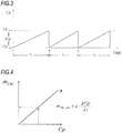
- the filter regeneration control unit 41 starts a filter regeneration in which the electric heater 34 is switched on when the electrostatic capacity Cp between the electrodes 32, 33 reaches a predetermined electrostatic capacity upper limit threshold Cp_ max which indicates a PM upper limit accumulation amount (refer to times t 1 , t 2 , t 3 in Fig. 3 ). This filter regeneration continues until the electrostatic capacity Cp is lowered to a predetermined electrostatic capacity lower limit threshold Cp_ min which indicates a complete removal of PM.
Landscapes
- Chemical & Material Sciences (AREA)
- Engineering & Computer Science (AREA)
- Immunology (AREA)
- Pathology (AREA)
- Health & Medical Sciences (AREA)
- Life Sciences & Earth Sciences (AREA)
- Analytical Chemistry (AREA)
- Biochemistry (AREA)
- General Health & Medical Sciences (AREA)
- General Physics & Mathematics (AREA)
- Physics & Mathematics (AREA)
- Chemical Kinetics & Catalysis (AREA)
- Combustion & Propulsion (AREA)
- Mechanical Engineering (AREA)
- General Engineering & Computer Science (AREA)
- Dispersion Chemistry (AREA)
- Electrochemistry (AREA)
- Processes For Solid Components From Exhaust (AREA)
- Investigating Or Analyzing Materials By The Use Of Electric Means (AREA)
- Filtering Of Dispersed Particles In Gases (AREA)
Abstract
Description
- The present invention relates to a sensor and more particularly to a PM sensor which detects a particular matter (hereinafter, referred to as PM) which is contained in exhaust gas.
- Conventionally, an electric resistance-type PM sensor has been known as a sensor which detects PM in exhaust gas discharged from an internal combustion engine. In a general electric resistance-type PM sensor, a pair of conductive electrodes are disposed in a face-to-face fashion on a surface of an insulated substrate, so that a PM amount is estimated by making use of the fact that an electric resistance value changes due to conductive PM (mainly, a soot component) adhering to these electrodes (for example, refer to Patent Literature 1).
- Patent Literature 1:
JP-A-2012-83210 - Incidentally, the electric resistance-type PM sensor has a simple construction in which PM is caused to adhere to each electrode. Therefore, in particular, under operating conditions where a flow rate of exhaust gas is increased, there is a possibility that part of the PM adhering to the electrodes may come off, leading to a problem that the estimation accuracy cannot be ensured. In addition, since the electric resistance of the PM adhering to the electrodes may change when it is subjected to the influence of the flow rate of exhaust gas, there is caused a problem that the PM amount cannot be estimated accurately. Further, an electric resistance value between the electrodes does not change until the electrodes are connected to each other by the accumulated PM. Owing to this, the amount of PM discharged from the engine cannot be estimated in real time, and hence, there is caused a problem that the application of the electric resistance-type PM sensor is limited to the on-board diagnosis of a failure in a position lying downstream of a diesel particulate filter (hereinafter, referred to as DPF).
- An object of the invention is to provide a PM sensor which can estimate an amount of PM contained in exhaust gas in real time while reducing a regeneration time effectively.
- With a view to achieving the object described above, according to the invention, there is provided a sensor including: a filter member having a plurality of cells which are defined by a porous partition wall and configured to trap particulate matters in exhaust gas; at least a pair of electrode members which are disposed to face each other with the cell sandwiched therebetween to form a condenser; a heater member which heats the cell to burn and remove particulate matters accumulated in the cell; and an estimation unit which estimates an amount of the particulate matters contained in the exhaust gas based on an electrostatic capacity between the pair of electrode members.
- The heater member may be a heating wire which is inserted into the cell and which is energized to be heated.
- The filter member may be a filter layer in which the plurality of cells are disposed in parallel in one direction, the pair of electrode members may be first and second planar electrode plates which are disposed to face each other with the filter layer sandwiched therebetween, the heater member may be a planar heater substrate which is energized to be heated, and the heater substrate may be interposed either between the first electrode plate and the filter layer or between the second electrode plate and the filter layer.
- The sensor may further include a filter regeneration control unit which executes a filter regeneration control in which, when the amount of particulate matters accumulated in the cells reaches a predetermined upper limit value, the accumulated particulate matters are burnt by the heater member and removed, and the estimation unit may estimate the amount of the particulate matters in real time by integrating regeneration interval periods from an end of a filter regeneration control to a start of a next filter regeneration control.
- The estimation unit may estimate a momentary amount of particulate matters in real time based on a variation in electrostatic capacity per unit time between the electrode members.
-
-
Fig. 1 is a schematic block diagram showing an example of an exhaust system to which a PM sensor of a first embodiment is applied. -
Fig. 2 is a schematic partial sectional view showing the PM sensor of the first embodiment. -
Fig. 3 is a timing chart illustrating a filter regeneration according to the first embodiment. -
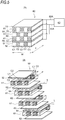
Fig. 4 is a diagram illustrating an example of a map according to the first embodiment. - In
Fig. 5 , (A) is a schematic perspective view showing a sensor unit according to the second embodiment, and (B) is a schematic exploded perspective view showing the sensor unit according to the second embodiment. -
Fig. 6 is a schematic block diagram showing an example of an exhaust system to which a PM sensor of another embodiment is applied. -
Fig. 7 is a schematic exploded perspective view showing the sensor unit of the other embodiment. - Hereinafter, PM sensors according to embodiments of the invention will be described based on the accompanying drawings. Same reference numerals will be given to same parts, and their designations and functions are also the same. Therefore, detailed descriptions of such parts will not be repeated.
-
Fig. 1 is a schematic block diagram showing an example of an exhaust system of a diesel engine (hereinafter, referred to simply as an engine) 100 to which aPM sensor 10 of a first embodiment is applied. Anoxidation catalyst 210, aDPF 220, aNOx removal catalyst 230 and the like are provided sequentially in that order from an upstream side of a flow of exhaust gas in anexhaust pipe 110 of theengine 100. ThePM sensor 10 of this embodiment may be provided, for example, either in a portion of theexhaust pipe 110 which lies upstream of theDPF 220 or in a portion of theexhaust pipe 110 which lies downstream of theDPF 220. - Next, a detailed configuration of the
PM sensor 10 according to the first embodiment will be described based onFig. 2 . - The
PM sensor 10 includes acase member 11 which is inserted in an interior of theexhaust pipe 110, aseat portion 20 where thecase member 11 is attached to theexhaust pipe 110, asensor unit 30 which is accommodated in thecase member 11, and acontrol unit 40. - The
case member 11 has a bottomed cylindrical shape which is closed on a bottom portion side (a lower end side in the illustrated example). A length L in an axial direction of thecase member 11 is made to be substantially the same length as a radius R of theexhaust pipe 110 so that a cylindrical wall portion on the bottom portion side protrudes as far as the vicinity of an axis center CL of theexhaust pipe 110. In the following description, the bottom portion side of thecase member 11 will be referred to as a distal end side, and an opposite side to the bottom portion side will be referred to as a proximal end side of thecase member 11. - A plurality of
inlet ports 12 are provided circumferentially at certain intervals in a cylindrical wall portion of thecase member 11 on the distal end side thereof. A plurality ofoutlet ports 13 are provided circumferentially at certain intervals in a cylindrical wall portion of thecase member 11 on the proximal end side thereof. A total opening area S12 of theinlet ports 12 is made to be smaller than a total opening area S13 of the outlet ports 13 (S12<S13). Namely, a flow velocity V12 of exhaust gas near theinlet ports 12 becomes slower than a flow velocity V13 of exhaust gas near the outlet ports 13 (V12<V13), whereby a pressure P12 on the side where theinlet ports 12 are provided becomes higher than a pressure P13 on the side where theoutlet ports 13 are provided (P12>P13). By doing so, exhaust gas is taken smoothly into thecase member 11 from theinlet ports 12, and at the same time, the exhaust gas inside thecase member 11 is discharged smoothly from theoutlet ports 13 into theexhaust pipe 110. - The
seat portion 20 includes anexternal thread portion 21 and anut portion 22. Theexternal thread portion 21 is provided at a proximal end portion of thecase member 11 and closes an opening portion at the proximal end side of thecase member 11. Thisexternal thread portion 21 is screwed into an internal thread portion of aboss portion 110A which is formed on theexhaust pipe 110. Thenut portion 22 is, for example, a hexagon nut and is fixed to an upper end portion of theexternal thread portion 21. A through hole (not shown) is formed in theexternal thread portion 21 and thenut portion 22 for passage ofconductive wires - The
sensor unit 30 includes afilter member 31, a plurality of pairs ofelectrodes 32, 33 and anelectric heater 34. - The
filter member 31 is made up, for example, of a plurality of cells which are defined by porous ceramic partition walls and serve as exhaust gas flow paths arranged in a grid-like fashion with upstream sides and downstream sides of the cells being plugged alternately. Thisfilter member 31 is held on an inner circumferential wall of thecase member 11 via acushion member 31A with the exhaust gas flow paths of the cells directed substantially parallel to the axial direction (a vertical direction in the figure) of thecase member 11. PM in exhaust gas taken into thecase member 11 from theinlet ports 12 are trapped on surfaces of the partition walls or in fine holes by allowing the exhaust gas so taken in to flow from the cell which is plugged at the downstream side thereof into the cell which is plugged at the upstream side thereof. In the following description, the cells which are plugged at the downstream side will be referred to as measuring cells, and the cells which are plugged at the upstream side will be referred to as electrode cells. - The
electrodes 32, 33 are, for example, conductive metallic wires and are inserted alternately into the electrode cells which face each other with the measuring cell sandwiched therebetween from the downstream sides (the sides which are not plugged) to form the condenser. Theseelectrodes 32, 33 are connected to an electrostatic capacity detection circuit, not shown, which is incorporated in thecontrol unit 40 viaconductive wires - The
electric heater 34 is, for example, a heating wire and executes a so-called filter regeneration in which theelectric heater 34 is energized to be heated so as to heat directly the measuring cells so that PM accumulated within the measuring cells are burnt and removed. Owing to this, theelectric heater 34 is bent so as to form continuous S-like shapes and is inserted into the measuring cells in such a way that straight-line portions which are parallel to each other extend along the flow paths of the measuring cells. - The
control unit 40 includes a filterregeneration control unit 41 and a PM amount estimation andcalculation unit 42 as functional elements. These functional elements will be described as being incorporated in thecontrol unit 40 which is integral hardware. However, the functional elements can also be provided in separate pieces of hardware. - The filter
regeneration control unit 41 executes a filter regeneration control in which theelectric heater 34 is switched on (energized) based on an electrostatic capacity Cp between theelectrodes 32, 33, which is detected by the electrostatic capacity detection circuit (not shown). The electrostatic capacity Cp between theelectrodes 32, 33 is expressed by the following expression 1 where a dielectric constant of a medium between theelectrodes 32, 33 is ε, a surface area of theelectrodes 32, 33 is S, and a distance between theelectrodes 32, 33 is d.
- In Expression 1, the surface areas of the
electrodes 32, 33 is constant, and when the dielectric constant ε and the distance d are changed by PM trapped in the measuring cell, the electrostatic capacity Cp is also changed in association with the changes in the dielectric constant ε and the distance d. Namely, a proportional relation is established between the electrostatic capacity Cp between theelectrodes 32, 33 and an amount of PM accumulated on thefilter member 31. The filterregeneration control unit 41 starts a filter regeneration in which theelectric heater 34 is switched on when the electrostatic capacity Cp between theelectrodes 32, 33 reaches a predetermined electrostatic capacity upper limit threshold Cp_max which indicates a PM upper limit accumulation amount (refer to times t1, t2, t3 inFig. 3 ). This filter regeneration continues until the electrostatic capacity Cp is lowered to a predetermined electrostatic capacity lower limit threshold Cp_min which indicates a complete removal of PM. - The PM estimation and
calculation unit 42 estimates a total PM amount mPM_sum of exhaust gas which is discharged from theengine 100 based on an electrostatic capacity variation ΔCpn during a regeneration interval Tn (from an end of a filter regeneration to a start of the next filter regeneration). A PM amount mPM_n of PM trapped on thefilter member 31 during the regeneration interval Tn is obtained by the following expression 2 in which the electrostatic capacity variation ΔCpn is multiplied by a primary coefficient β.
- The PM amount estimation and
calculation unit 42 calculates a total PM amount mPM_sum in exhaust gas discharged from theengine 100 in real time based on the following expression 3 in which PM amounts mPM_n during each regeneration interval Tn, which are calculated from Expression 2, are integrated sequentially.
- It is also possible to estimate in real time a momentary PM amount mPM_new of PM contained in exhaust gas from a variation ΔCp/Δt in electrostatic capacity Cp per unit time. In this case, a map (refer to
Fig. 4 ) showing a relation between the electrostatic capacity CP and the PM amount mPM which is obtained in advance through experiments and the like is used, and the momentary PM amount mPM_new can be obtained by multiplying the map by the momentary variation ΔCp/Δt in electrostatic capacity Cp. In a case where the momentary PM amount mPM_new is estimated in the way described above, by providing thePM sensor 10 in the portion of theexhaust pipe 110 which lies upstream of theDPF 220, since the momentary PM amount mPM_new of PM discharged from theengine 100 can be estimated in real time, an engine control such as a smoke limit control can be executed effectively. - Next, working effects of the
PM sensor 10 according to this embodiment will be described. - In the electric resistance-type PM sensor in which a PM amount is estimated based on an electric resistance value between the electrodes, it becomes difficult for PM accumulated to be kept adhering to the electrodes in an ensured fashion when the flow rate of the exhaust gas is increased, and this causes the problem that the estimation accuracy cannot be ensured. In addition, since the electric resistance of the PM adhering to the electrodes may change when it is subjected to the influence of the flow rate of the exhaust gas, there is caused a problem that the PM amount cannot be estimated accurately. Further, since the electric resistance value between the electrodes does not change until the electrodes are connected to each other by the PM accumulated, there is also caused a problem that the PM amount cannot be estimated in real time.
- In contrast with the electric resistance-type PM sensor, the
PM sensor 10 of this embodiment calculates in real time a total PM amount mPM_sum of PM in the exhaust gas discharged from theengine 100 by trapping PM in the exhaust gas by thefilter member 31 in an ensured fashion and sequentially integrating PM amounts mPM_n during each individual regeneration interval Tn. Consequently, according to thePM sensor 10 of this embodiment, the total PM amount mPM_sum of PM discharged from theengine 100 can be estimated highly accurately and in real time. In particular, in case a momentary PM amount mPM_new is made to be estimated from a variation ΔCp/Δt in electrostatic capacity per unit time, the engine control can be executed effectively by providing thePM sensor 10 upstream of theDPF 220. In addition, in the case of thePM sensor 10 being provided downstream of theDPF 220, an onboard failure detection of theDPF 220 can be executed highly accurately and early. - With the
PM sensor 10 of this embodiment, theelectric heater 34 is inserted into the measuring cells so as to heat directly the PM accumulated in the measuring cells at the time of filter regeneration. Consequently, according to thePM sensor 10 of this embodiment, the PM accumulated in the measuring cells can be burnt and removed with good efficiency, thereby making it possible to reduce the filter regeneration time effectively. - Next, a PM sensor according to a second embodiment will be described in detail based on
Fig. 5 . The PM sensor of the second embodiment is such that a laminated sensor unit is used in place of thesensor unit 30 in the first embodiment. - The other constituent elements remain the same, and hence, the detailed description and illustration thereof will be omitted here.
- (A) of
Fig. 5 is a perspective view of asensor unit 60 of the second embodiment, and (B) ofFig. 5 is an exploded perspective view of thesensor unit 60. Thesensor unit 60 includes a plurality of filter layers 61, pluralities of first andsecond electrode plates heater substrates 64. - The filter layers 61 each have a rectangular parallelepiped shape in which a plurality of cells are defined by porous ceramic partition walls and serve as an exhaust gas flow path with upstream sides and downstream sides of the cells being plugged alternately and in which the cells are disposed in parallel in one direction. PM contained in exhaust gas is trapped on surfaces of the partition walls or in fine holes of the cell C1 as a result of the exhaust gas flowing from the cell C1 which is plugged at the downstream side thereof into the cell C2 which is plugged at the upstream side thereof, as indicated by arrows at leading ends of broken lines in (b) of
Fig. 5 . In the following description, a flowing direction of exhaust gas in the exhaust gas flow path in each cell will be referred to as a lengthwise direction (denoted by arrows L in (A) ofFig. 5 ) of thesensor unit 60 and a direction which is at right angles to the flowing direction of exhaust gas in the exhaust gas flow path will be referred to as a widthwise direction (denoted by arrows W in (A) ofFig. 5 ) of thesensor unit 60. - The first and
second electrode plates filter layer 61. The first andsecond electrode plates filter layer 61 sandwiched therebetween and are connected to an electrostatic capacity detection circuit, not shown, which is incorporated in acontrol unit 40 viaconductive wires - Namely, the
first electrode plate 62 and thesecond electrode plate 63 are disposed so as to face each other, and thefilter layer 61 is sandwiched between theelectrode plates planar electrode plates - The
heater substrate 64 is made up, for example, of a planar heat-resistant and insulating member with good heat conductivity and is formed so that its external dimensions in the lengthwise direction L and widthwise direction W coincide substantially with those of thefilter layer 61. A heating wire L (shown only in (B) ofFig. 5 ) which is energized to be heated is embedded in an interior of theheater substrate 64 in such a way as to be bent so as to form continuous S-like shapes. In this embodiment, theheater substrate 64 is interposed between thesecond electrode plate 63 and thefilter layer 61. - Namely, when a filter regeneration is executed, the heating wire L is energized to heat directly the interior of the cell C1. By doing so, PM accumulated in the cell C1 can be burnt and removed with good efficiency, whereby the filter regeneration time can be reduced effectively.
- The position where the
heater substrate 64 is provided is not limited to the position lying between thesecond electrode plate 63 and thefilter layer 61, and hence, theheater substrate 64 may be provided between thefirst electrode plate 62 and thefilter layer 61. In addition, a configuration may be adopted in which with theheater substrate 64 omitted, a voltage is applied directly to theelectrode plates - The invention is not limited to the embodiments that have been described heretofore and hence can be carried out by being modified as required without departing from the spirit and scope of the invention.
- For example, as shown in
Fig. 6 , a configuration may be adopted in which abypass pipe 120 is connected to anexhaust pipe 110 which branches off theexhaust pipe 110 from a position lying between anoxidation catalyst 210 and aDPF 220 and which merges back to theexhaust pipe 110 upstream of aNOx removal catalyst 230, and thesensor unit 30 of the first embodiment or thesensor unit 60 of the second embodiment is disposed within thebypass pipe 120. - In addition, as shown in
Fig. 7 , a configuration may be adopted in which theheater substrate 64 of the second embodiment is replaced with theelectric heater 34 of the first embodiment.
Claims (5)
- A sensor comprising:a filter member having a plurality of cells which are defined by a porous partition wall and configured to trap particulate matters in exhaust gas;at least a pair of electrode members which are disposed to face each other with the cell sandwiched therebetween to form a condenser;a heater member which heats the cell to burn and remove particulate matters accumulated in the cell; andan estimation unit which estimates an amount of the particulate matters contained in the exhaust gas based on an electrostatic capacity between the pair of electrode members.
- The sensor according to claim 1,
wherein the heater member is a heating wire which is inserted into the cell and which is energized to be heated. - The sensor according to claim 1,
wherein the filter member is a filter layer in which the plurality of cells are disposed in parallel in one direction,
wherein the pair of electrode members are first and second planar electrode plates which are disposed to face each other with the filter layer sandwiched therebetween,
wherein the heater member is a planar heater substrate which is energized to be heated, and
wherein the heater substrate is interposed either between the first electrode plate and the filter layer or between the second electrode plate and the filter layer. - The sensor according to any one of claims 1 to 3, further comprising:filter regeneration means capable of executing a filter regeneration in which, when an amount of particulate matters trapped by the filter member reaches a predetermined value, the accumulated particulate matters are burnt and removed,wherein the estimation unit estimates the amount of the particulate matters in the exhaust gas in real time by calculating an amount of particulate matters trapped by the filter member during a regeneration interval from a variation in electrostatic capacity during the regeneration interval and sequentially integrating the amounts of the particulate matters which are calculated during each regeneration interval.
- The sensor according to any one of claims 1 to 3,
wherein the estimation unit estimates a momentary amount of particulate matters in real time based on a variation in electrostatic capacity per unit time between the electrode members.
Applications Claiming Priority (2)
| Application Number | Priority Date | Filing Date | Title |
|---|---|---|---|
| JP2014128599A JP6507497B2 (en) | 2014-06-23 | 2014-06-23 | Sensor |
| PCT/JP2015/066895 WO2015198884A1 (en) | 2014-06-23 | 2015-06-11 | Sensor |
Publications (3)
| Publication Number | Publication Date |
|---|---|
| EP3159685A1 true EP3159685A1 (en) | 2017-04-26 |
| EP3159685A4 EP3159685A4 (en) | 2018-04-04 |
| EP3159685B1 EP3159685B1 (en) | 2021-08-11 |
Family
ID=54937975
Family Applications (1)
| Application Number | Title | Priority Date | Filing Date |
|---|---|---|---|
| EP15811540.2A Active EP3159685B1 (en) | 2014-06-23 | 2015-06-11 | Sensor |
Country Status (5)
| Country | Link |
|---|---|
| US (1) | US10364730B2 (en) |
| EP (1) | EP3159685B1 (en) |
| JP (1) | JP6507497B2 (en) |
| CN (1) | CN107076692B (en) |
| WO (1) | WO2015198884A1 (en) |
Cited By (3)
| Publication number | Priority date | Publication date | Assignee | Title |
|---|---|---|---|---|
| EP3181844A4 (en) * | 2014-08-11 | 2018-02-07 | Isuzu Motors Limited | Sensor |
| EP3181845A4 (en) * | 2014-08-11 | 2018-02-07 | Isuzu Motors Limited | Sensor |
| CN108885164A (en) * | 2016-03-31 | 2018-11-23 | 阿莫泰克有限公司 | Particulate matter detection sensor |
Families Citing this family (3)
| Publication number | Priority date | Publication date | Assignee | Title |
|---|---|---|---|---|
| JP2017191050A (en) * | 2016-04-14 | 2017-10-19 | いすゞ自動車株式会社 | Sensor |
| JP6805531B2 (en) * | 2016-04-14 | 2020-12-23 | いすゞ自動車株式会社 | Sensor |
| US10392999B2 (en) * | 2016-10-11 | 2019-08-27 | Ford Global Technologies, Llc | Method and system for exhaust particulate matter sensing |
Family Cites Families (34)
| Publication number | Priority date | Publication date | Assignee | Title |
|---|---|---|---|---|
| US3226615A (en) * | 1962-06-19 | 1965-12-28 | Buell Engineering Company Inc | Capacitive probe and system for regulating gases |
| US4158610A (en) * | 1978-03-28 | 1979-06-19 | Bethlehem Steel Corporation | Method and apparatus for determining and controlling amount of carbon deposited on a surface by a gas |
| JPS578311A (en) * | 1980-06-19 | 1982-01-16 | Toyota Motor Corp | Method and device for decreasing discharged quantity of diesel particulates |
| US4283207A (en) * | 1980-06-19 | 1981-08-11 | General Motors Corporation | Diesel exhaust filter-incinerator |
| JPS6053165B2 (en) * | 1981-03-16 | 1985-11-25 | 株式会社豊田中央研究所 | Internal combustion engine exhaust smoke collection device |
| US4656832A (en) * | 1982-09-30 | 1987-04-14 | Nippondenso Co., Ltd. | Detector for particulate density and filter with detector for particulate density |
| US5250094A (en) * | 1992-03-16 | 1993-10-05 | Donaldson Company, Inc. | Ceramic filter construction and method |
| JPH06257422A (en) | 1993-01-06 | 1994-09-13 | Sumitomo Electric Ind Ltd | Particulate trap for diesel engine |
| US5423904A (en) * | 1993-05-28 | 1995-06-13 | Dasgupta; Sankar | Exhaust gas filter |
| EP1287242A1 (en) * | 2000-06-01 | 2003-03-05 | Blue Planet Co., Ltd | Apparatus for removing soot and no x? in exhaust gas from diesel engines |
| JP2003098135A (en) * | 2001-09-27 | 2003-04-03 | Horiba Ltd | Granular substance sensor and method for measuring granular substance using the same |
| JP2003201823A (en) * | 2002-10-15 | 2003-07-18 | Ibiden Co Ltd | Filter for exhaust emission control device |
| DE10353860B4 (en) * | 2003-11-18 | 2023-03-30 | Robert Bosch Gmbh | Sensor for detecting particles in a gas stream and method for its manufacture |
| US7469532B2 (en) * | 2005-09-22 | 2008-12-30 | Gm Global Technology Operations, Inc. | Diesel particulate filter (DPF) regeneration by electrical heating of resistive coatings |
| US8549846B2 (en) * | 2006-03-24 | 2013-10-08 | GM Global Technology Operations LLC | Diesel particulate filter regeneration via resistive surface heating |
| EP1914537A1 (en) * | 2006-10-17 | 2008-04-23 | Ibiden Co., Ltd. | Particulate matter sensor |
| JP2009097410A (en) * | 2007-10-16 | 2009-05-07 | Toyota Motor Corp | PM collection amount estimation device and filter regeneration system for particulate filter |
| JP4758488B2 (en) * | 2009-02-16 | 2011-08-31 | 本田技研工業株式会社 | Particulate matter detector |
| JP5568322B2 (en) * | 2009-03-25 | 2014-08-06 | 日本碍子株式会社 | Particulate matter accumulation detection device |
| JP4798813B1 (en) * | 2010-03-24 | 2011-10-19 | 日本碍子株式会社 | Method for detecting particulate matter |
| JP5617764B2 (en) * | 2010-09-27 | 2014-11-05 | 株式会社デンソー | Honeycomb structure and electrically heated catalyst device |
| JP2012083210A (en) | 2010-10-12 | 2012-04-26 | Denso Corp | Particulate substance detection sensor |
| JP5201193B2 (en) * | 2010-10-28 | 2013-06-05 | 株式会社デンソー | Particulate matter detection sensor |
| JP5625812B2 (en) * | 2010-11-29 | 2014-11-19 | いすゞ自動車株式会社 | PM sensor and PM sensor manufacturing method |
| JP5874196B2 (en) | 2011-05-20 | 2016-03-02 | いすゞ自動車株式会社 | Particulate matter sensor |
| JP5874195B2 (en) | 2011-05-20 | 2016-03-02 | いすゞ自動車株式会社 | Particulate matter sensor |
| JP5924669B2 (en) * | 2012-03-27 | 2016-05-25 | 本田技研工業株式会社 | Particulate matter detector |
| US9151205B2 (en) * | 2013-02-15 | 2015-10-06 | Indiana University Research & Technology Corporation | Real-time soot measurement in a diesel particulate filter |
| JP6089763B2 (en) * | 2013-02-20 | 2017-03-08 | いすゞ自動車株式会社 | Particulate matter measuring device |
| JP6028615B2 (en) * | 2013-02-20 | 2016-11-16 | いすゞ自動車株式会社 | Particulate matter measuring device |
| JP6379837B2 (en) * | 2014-08-11 | 2018-08-29 | いすゞ自動車株式会社 | Sensor |
| JP6459437B2 (en) * | 2014-11-26 | 2019-01-30 | いすゞ自動車株式会社 | Diagnostic device and sensor |
| JP2016153737A (en) * | 2015-02-20 | 2016-08-25 | いすゞ自動車株式会社 | Sensor |
| JP2016153610A (en) * | 2015-02-20 | 2016-08-25 | いすゞ自動車株式会社 | Exhaust emission control device |
-
2014
- 2014-06-23 JP JP2014128599A patent/JP6507497B2/en not_active Expired - Fee Related
-
2015
- 2015-06-11 WO PCT/JP2015/066895 patent/WO2015198884A1/en not_active Ceased
- 2015-06-11 US US15/321,446 patent/US10364730B2/en active Active
- 2015-06-11 CN CN201580033488.0A patent/CN107076692B/en active Active
- 2015-06-11 EP EP15811540.2A patent/EP3159685B1/en active Active
Cited By (6)
| Publication number | Priority date | Publication date | Assignee | Title |
|---|---|---|---|---|
| EP3181844A4 (en) * | 2014-08-11 | 2018-02-07 | Isuzu Motors Limited | Sensor |
| EP3181845A4 (en) * | 2014-08-11 | 2018-02-07 | Isuzu Motors Limited | Sensor |
| US10126205B2 (en) | 2014-08-11 | 2018-11-13 | Isuzu Motors Limited | Sensor |
| US10337434B2 (en) | 2014-08-11 | 2019-07-02 | Isuzu Motors Limited | Particulate matter (PM) sensor |
| CN108885164A (en) * | 2016-03-31 | 2018-11-23 | 阿莫泰克有限公司 | Particulate matter detection sensor |
| CN108885164B (en) * | 2016-03-31 | 2020-09-01 | 阿莫泰克有限公司 | Particulate matter sensor |
Also Published As
| Publication number | Publication date |
|---|---|
| CN107076692B (en) | 2020-06-30 |
| EP3159685A4 (en) | 2018-04-04 |
| EP3159685B1 (en) | 2021-08-11 |
| JP6507497B2 (en) | 2019-05-08 |
| JP2016008863A (en) | 2016-01-18 |
| US20170159536A1 (en) | 2017-06-08 |
| US10364730B2 (en) | 2019-07-30 |
| WO2015198884A1 (en) | 2015-12-30 |
| CN107076692A (en) | 2017-08-18 |
Similar Documents
| Publication | Publication Date | Title |
|---|---|---|
| EP3225800B1 (en) | Diagnostic device and sensor | |
| US10364730B2 (en) | Sensor | |
| JP6409452B2 (en) | Diagnostic equipment | |
| US20180038251A1 (en) | Exhaust purification device | |
| EP3181844B1 (en) | Sensor | |
| JP6361314B2 (en) | Sensor | |
| US10481061B2 (en) | Sensor for detecting an emission amount of particulate matter | |
| EP3181845B1 (en) | Sensor | |
| EP3260854B1 (en) | Sensor and method for detecting water | |
| JP6458368B2 (en) | Sensor | |
| JP6409437B2 (en) | Sensor | |
| JP6784050B2 (en) | Sensor | |
| JP6417780B2 (en) | Sensor | |
| JP6451179B2 (en) | Diagnostic equipment | |
| JP2016061679A (en) | Diagnostic equipment |
Legal Events
| Date | Code | Title | Description |
|---|---|---|---|
| STAA | Information on the status of an ep patent application or granted ep patent |
Free format text: STATUS: THE INTERNATIONAL PUBLICATION HAS BEEN MADE |
|
| PUAI | Public reference made under article 153(3) epc to a published international application that has entered the european phase |
Free format text: ORIGINAL CODE: 0009012 |
|
| STAA | Information on the status of an ep patent application or granted ep patent |
Free format text: STATUS: REQUEST FOR EXAMINATION WAS MADE |
|
| 17P | Request for examination filed |
Effective date: 20170123 |
|
| AK | Designated contracting states |
Kind code of ref document: A1 Designated state(s): AL AT BE BG CH CY CZ DE DK EE ES FI FR GB GR HR HU IE IS IT LI LT LU LV MC MK MT NL NO PL PT RO RS SE SI SK SM TR |
|
| AX | Request for extension of the european patent |
Extension state: BA ME |
|
| DAV | Request for validation of the european patent (deleted) | ||
| DAX | Request for extension of the european patent (deleted) | ||
| A4 | Supplementary search report drawn up and despatched |
Effective date: 20180302 |
|
| RIC1 | Information provided on ipc code assigned before grant |
Ipc: G01N 15/06 20060101ALI20180226BHEP Ipc: F01N 11/00 20060101ALI20180226BHEP Ipc: F01N 3/023 20060101ALI20180226BHEP Ipc: B01D 46/42 20060101ALI20180226BHEP Ipc: F01N 3/027 20060101ALI20180226BHEP Ipc: B01D 46/24 20060101ALN20180226BHEP Ipc: G01N 27/22 20060101AFI20180226BHEP Ipc: B01D 46/00 20060101ALN20180226BHEP |
|
| STAA | Information on the status of an ep patent application or granted ep patent |
Free format text: STATUS: EXAMINATION IS IN PROGRESS |
|
| 17Q | First examination report despatched |
Effective date: 20181206 |
|
| GRAP | Despatch of communication of intention to grant a patent |
Free format text: ORIGINAL CODE: EPIDOSNIGR1 |
|
| STAA | Information on the status of an ep patent application or granted ep patent |
Free format text: STATUS: GRANT OF PATENT IS INTENDED |
|
| RIC1 | Information provided on ipc code assigned before grant |
Ipc: B01D 46/42 20060101ALI20210127BHEP Ipc: G01N 15/06 20060101ALI20210127BHEP Ipc: G01N 1/22 20060101ALN20210127BHEP Ipc: G01N 27/22 20060101AFI20210127BHEP Ipc: F01N 3/027 20060101ALI20210127BHEP Ipc: B01D 46/00 20060101ALN20210127BHEP Ipc: B01D 46/24 20060101ALN20210127BHEP Ipc: F01N 3/023 20060101ALI20210127BHEP Ipc: F01N 11/00 20060101ALI20210127BHEP |
|
| INTG | Intention to grant announced |
Effective date: 20210301 |
|
| GRAS | Grant fee paid |
Free format text: ORIGINAL CODE: EPIDOSNIGR3 |
|
| GRAA | (expected) grant |
Free format text: ORIGINAL CODE: 0009210 |
|
| STAA | Information on the status of an ep patent application or granted ep patent |
Free format text: STATUS: THE PATENT HAS BEEN GRANTED |
|
| AK | Designated contracting states |
Kind code of ref document: B1 Designated state(s): AL AT BE BG CH CY CZ DE DK EE ES FI FR GB GR HR HU IE IS IT LI LT LU LV MC MK MT NL NO PL PT RO RS SE SI SK SM TR |
|
| REG | Reference to a national code |
Ref country code: CH Ref legal event code: EP |
|
| REG | Reference to a national code |
Ref country code: DE Ref legal event code: R096 Ref document number: 602015072242 Country of ref document: DE |
|
| REG | Reference to a national code |
Ref country code: IE Ref legal event code: FG4D Ref country code: AT Ref legal event code: REF Ref document number: 1419882 Country of ref document: AT Kind code of ref document: T Effective date: 20210915 |
|
| REG | Reference to a national code |
Ref country code: LT Ref legal event code: MG9D |
|
| REG | Reference to a national code |
Ref country code: NL Ref legal event code: MP Effective date: 20210811 |
|
| REG | Reference to a national code |
Ref country code: AT Ref legal event code: MK05 Ref document number: 1419882 Country of ref document: AT Kind code of ref document: T Effective date: 20210811 |
|
| PG25 | Lapsed in a contracting state [announced via postgrant information from national office to epo] |
Ref country code: RS Free format text: LAPSE BECAUSE OF FAILURE TO SUBMIT A TRANSLATION OF THE DESCRIPTION OR TO PAY THE FEE WITHIN THE PRESCRIBED TIME-LIMIT Effective date: 20210811 Ref country code: SE Free format text: LAPSE BECAUSE OF FAILURE TO SUBMIT A TRANSLATION OF THE DESCRIPTION OR TO PAY THE FEE WITHIN THE PRESCRIBED TIME-LIMIT Effective date: 20210811 Ref country code: HR Free format text: LAPSE BECAUSE OF FAILURE TO SUBMIT A TRANSLATION OF THE DESCRIPTION OR TO PAY THE FEE WITHIN THE PRESCRIBED TIME-LIMIT Effective date: 20210811 Ref country code: NO Free format text: LAPSE BECAUSE OF FAILURE TO SUBMIT A TRANSLATION OF THE DESCRIPTION OR TO PAY THE FEE WITHIN THE PRESCRIBED TIME-LIMIT Effective date: 20211111 Ref country code: PT Free format text: LAPSE BECAUSE OF FAILURE TO SUBMIT A TRANSLATION OF THE DESCRIPTION OR TO PAY THE FEE WITHIN THE PRESCRIBED TIME-LIMIT Effective date: 20211213 Ref country code: ES Free format text: LAPSE BECAUSE OF FAILURE TO SUBMIT A TRANSLATION OF THE DESCRIPTION OR TO PAY THE FEE WITHIN THE PRESCRIBED TIME-LIMIT Effective date: 20210811 Ref country code: FI Free format text: LAPSE BECAUSE OF FAILURE TO SUBMIT A TRANSLATION OF THE DESCRIPTION OR TO PAY THE FEE WITHIN THE PRESCRIBED TIME-LIMIT Effective date: 20210811 Ref country code: BG Free format text: LAPSE BECAUSE OF FAILURE TO SUBMIT A TRANSLATION OF THE DESCRIPTION OR TO PAY THE FEE WITHIN THE PRESCRIBED TIME-LIMIT Effective date: 20211111 Ref country code: AT Free format text: LAPSE BECAUSE OF FAILURE TO SUBMIT A TRANSLATION OF THE DESCRIPTION OR TO PAY THE FEE WITHIN THE PRESCRIBED TIME-LIMIT Effective date: 20210811 Ref country code: LT Free format text: LAPSE BECAUSE OF FAILURE TO SUBMIT A TRANSLATION OF THE DESCRIPTION OR TO PAY THE FEE WITHIN THE PRESCRIBED TIME-LIMIT Effective date: 20210811 |
|
| PG25 | Lapsed in a contracting state [announced via postgrant information from national office to epo] |
Ref country code: PL Free format text: LAPSE BECAUSE OF FAILURE TO SUBMIT A TRANSLATION OF THE DESCRIPTION OR TO PAY THE FEE WITHIN THE PRESCRIBED TIME-LIMIT Effective date: 20210811 Ref country code: LV Free format text: LAPSE BECAUSE OF FAILURE TO SUBMIT A TRANSLATION OF THE DESCRIPTION OR TO PAY THE FEE WITHIN THE PRESCRIBED TIME-LIMIT Effective date: 20210811 Ref country code: GR Free format text: LAPSE BECAUSE OF FAILURE TO SUBMIT A TRANSLATION OF THE DESCRIPTION OR TO PAY THE FEE WITHIN THE PRESCRIBED TIME-LIMIT Effective date: 20211112 |
|
| PG25 | Lapsed in a contracting state [announced via postgrant information from national office to epo] |
Ref country code: NL Free format text: LAPSE BECAUSE OF FAILURE TO SUBMIT A TRANSLATION OF THE DESCRIPTION OR TO PAY THE FEE WITHIN THE PRESCRIBED TIME-LIMIT Effective date: 20210811 |
|
| PG25 | Lapsed in a contracting state [announced via postgrant information from national office to epo] |
Ref country code: DK Free format text: LAPSE BECAUSE OF FAILURE TO SUBMIT A TRANSLATION OF THE DESCRIPTION OR TO PAY THE FEE WITHIN THE PRESCRIBED TIME-LIMIT Effective date: 20210811 |
|
| REG | Reference to a national code |
Ref country code: DE Ref legal event code: R097 Ref document number: 602015072242 Country of ref document: DE |
|
| PG25 | Lapsed in a contracting state [announced via postgrant information from national office to epo] |
Ref country code: SM Free format text: LAPSE BECAUSE OF FAILURE TO SUBMIT A TRANSLATION OF THE DESCRIPTION OR TO PAY THE FEE WITHIN THE PRESCRIBED TIME-LIMIT Effective date: 20210811 Ref country code: SK Free format text: LAPSE BECAUSE OF FAILURE TO SUBMIT A TRANSLATION OF THE DESCRIPTION OR TO PAY THE FEE WITHIN THE PRESCRIBED TIME-LIMIT Effective date: 20210811 Ref country code: RO Free format text: LAPSE BECAUSE OF FAILURE TO SUBMIT A TRANSLATION OF THE DESCRIPTION OR TO PAY THE FEE WITHIN THE PRESCRIBED TIME-LIMIT Effective date: 20210811 Ref country code: EE Free format text: LAPSE BECAUSE OF FAILURE TO SUBMIT A TRANSLATION OF THE DESCRIPTION OR TO PAY THE FEE WITHIN THE PRESCRIBED TIME-LIMIT Effective date: 20210811 Ref country code: CZ Free format text: LAPSE BECAUSE OF FAILURE TO SUBMIT A TRANSLATION OF THE DESCRIPTION OR TO PAY THE FEE WITHIN THE PRESCRIBED TIME-LIMIT Effective date: 20210811 Ref country code: AL Free format text: LAPSE BECAUSE OF FAILURE TO SUBMIT A TRANSLATION OF THE DESCRIPTION OR TO PAY THE FEE WITHIN THE PRESCRIBED TIME-LIMIT Effective date: 20210811 |
|
| PLBE | No opposition filed within time limit |
Free format text: ORIGINAL CODE: 0009261 |
|
| STAA | Information on the status of an ep patent application or granted ep patent |
Free format text: STATUS: NO OPPOSITION FILED WITHIN TIME LIMIT |
|
| 26N | No opposition filed |
Effective date: 20220512 |
|
| PG25 | Lapsed in a contracting state [announced via postgrant information from national office to epo] |
Ref country code: IT Free format text: LAPSE BECAUSE OF FAILURE TO SUBMIT A TRANSLATION OF THE DESCRIPTION OR TO PAY THE FEE WITHIN THE PRESCRIBED TIME-LIMIT Effective date: 20210811 |
|
| PGFP | Annual fee paid to national office [announced via postgrant information from national office to epo] |
Ref country code: GB Payment date: 20220428 Year of fee payment: 8 Ref country code: FR Payment date: 20220510 Year of fee payment: 8 |
|
| PG25 | Lapsed in a contracting state [announced via postgrant information from national office to epo] |
Ref country code: SI Free format text: LAPSE BECAUSE OF FAILURE TO SUBMIT A TRANSLATION OF THE DESCRIPTION OR TO PAY THE FEE WITHIN THE PRESCRIBED TIME-LIMIT Effective date: 20210811 |
|
| PG25 | Lapsed in a contracting state [announced via postgrant information from national office to epo] |
Ref country code: MC Free format text: LAPSE BECAUSE OF FAILURE TO SUBMIT A TRANSLATION OF THE DESCRIPTION OR TO PAY THE FEE WITHIN THE PRESCRIBED TIME-LIMIT Effective date: 20210811 |
|
| REG | Reference to a national code |
Ref country code: CH Ref legal event code: PL |
|
| REG | Reference to a national code |
Ref country code: BE Ref legal event code: MM Effective date: 20220630 |
|
| PG25 | Lapsed in a contracting state [announced via postgrant information from national office to epo] |
Ref country code: LU Free format text: LAPSE BECAUSE OF NON-PAYMENT OF DUE FEES Effective date: 20220611 Ref country code: LI Free format text: LAPSE BECAUSE OF NON-PAYMENT OF DUE FEES Effective date: 20220630 Ref country code: IE Free format text: LAPSE BECAUSE OF NON-PAYMENT OF DUE FEES Effective date: 20220611 Ref country code: CH Free format text: LAPSE BECAUSE OF NON-PAYMENT OF DUE FEES Effective date: 20220630 |
|
| PG25 | Lapsed in a contracting state [announced via postgrant information from national office to epo] |
Ref country code: BE Free format text: LAPSE BECAUSE OF NON-PAYMENT OF DUE FEES Effective date: 20220630 |
|
| GBPC | Gb: european patent ceased through non-payment of renewal fee |
Effective date: 20230611 |
|
| PG25 | Lapsed in a contracting state [announced via postgrant information from national office to epo] |
Ref country code: HU Free format text: LAPSE BECAUSE OF FAILURE TO SUBMIT A TRANSLATION OF THE DESCRIPTION OR TO PAY THE FEE WITHIN THE PRESCRIBED TIME-LIMIT; INVALID AB INITIO Effective date: 20150611 |
|
| PG25 | Lapsed in a contracting state [announced via postgrant information from national office to epo] |
Ref country code: MK Free format text: LAPSE BECAUSE OF FAILURE TO SUBMIT A TRANSLATION OF THE DESCRIPTION OR TO PAY THE FEE WITHIN THE PRESCRIBED TIME-LIMIT Effective date: 20210811 Ref country code: CY Free format text: LAPSE BECAUSE OF FAILURE TO SUBMIT A TRANSLATION OF THE DESCRIPTION OR TO PAY THE FEE WITHIN THE PRESCRIBED TIME-LIMIT Effective date: 20210811 Ref country code: GB Free format text: LAPSE BECAUSE OF NON-PAYMENT OF DUE FEES Effective date: 20230611 |
|
| REG | Reference to a national code |
Ref country code: DE Ref legal event code: R082 Ref document number: 602015072242 Country of ref document: DE Representative=s name: MEISSNER BOLTE PATENTANWAELTE RECHTSANWAELTE P, DE |
|
| PG25 | Lapsed in a contracting state [announced via postgrant information from national office to epo] |
Ref country code: FR Free format text: LAPSE BECAUSE OF NON-PAYMENT OF DUE FEES Effective date: 20230630 |
|
| PG25 | Lapsed in a contracting state [announced via postgrant information from national office to epo] |
Ref country code: TR Free format text: LAPSE BECAUSE OF FAILURE TO SUBMIT A TRANSLATION OF THE DESCRIPTION OR TO PAY THE FEE WITHIN THE PRESCRIBED TIME-LIMIT Effective date: 20210811 |
|
| PG25 | Lapsed in a contracting state [announced via postgrant information from national office to epo] |
Ref country code: MT Free format text: LAPSE BECAUSE OF FAILURE TO SUBMIT A TRANSLATION OF THE DESCRIPTION OR TO PAY THE FEE WITHIN THE PRESCRIBED TIME-LIMIT Effective date: 20210811 |
|
| PGFP | Annual fee paid to national office [announced via postgrant information from national office to epo] |
Ref country code: DE Payment date: 20250520 Year of fee payment: 11 |