EP3159607A1 - Hallenleuchte - Google Patents
Hallenleuchte Download PDFInfo
- Publication number
- EP3159607A1 EP3159607A1 EP15191290.4A EP15191290A EP3159607A1 EP 3159607 A1 EP3159607 A1 EP 3159607A1 EP 15191290 A EP15191290 A EP 15191290A EP 3159607 A1 EP3159607 A1 EP 3159607A1
- Authority
- EP
- European Patent Office
- Prior art keywords
- heat dissipation
- high bay
- bay light
- heat
- disk
- Prior art date
- Legal status (The legal status is an assumption and is not a legal conclusion. Google has not performed a legal analysis and makes no representation as to the accuracy of the status listed.)
- Withdrawn
Links
Images


Classifications
-
- F—MECHANICAL ENGINEERING; LIGHTING; HEATING; WEAPONS; BLASTING
- F21—LIGHTING
- F21V—FUNCTIONAL FEATURES OR DETAILS OF LIGHTING DEVICES OR SYSTEMS THEREOF; STRUCTURAL COMBINATIONS OF LIGHTING DEVICES WITH OTHER ARTICLES, NOT OTHERWISE PROVIDED FOR
- F21V29/00—Protecting lighting devices from thermal damage; Cooling or heating arrangements specially adapted for lighting devices or systems
- F21V29/50—Cooling arrangements
- F21V29/502—Cooling arrangements characterised by the adaptation for cooling of specific components
- F21V29/503—Cooling arrangements characterised by the adaptation for cooling of specific components of light sources
-
- F—MECHANICAL ENGINEERING; LIGHTING; HEATING; WEAPONS; BLASTING
- F21—LIGHTING
- F21V—FUNCTIONAL FEATURES OR DETAILS OF LIGHTING DEVICES OR SYSTEMS THEREOF; STRUCTURAL COMBINATIONS OF LIGHTING DEVICES WITH OTHER ARTICLES, NOT OTHERWISE PROVIDED FOR
- F21V29/00—Protecting lighting devices from thermal damage; Cooling or heating arrangements specially adapted for lighting devices or systems
- F21V29/50—Cooling arrangements
- F21V29/70—Cooling arrangements characterised by passive heat-dissipating elements, e.g. heat-sinks
- F21V29/71—Cooling arrangements characterised by passive heat-dissipating elements, e.g. heat-sinks using a combination of separate elements interconnected by heat-conducting means, e.g. with heat pipes or thermally conductive bars between separate heat-sink elements
-
- F—MECHANICAL ENGINEERING; LIGHTING; HEATING; WEAPONS; BLASTING
- F21—LIGHTING
- F21V—FUNCTIONAL FEATURES OR DETAILS OF LIGHTING DEVICES OR SYSTEMS THEREOF; STRUCTURAL COMBINATIONS OF LIGHTING DEVICES WITH OTHER ARTICLES, NOT OTHERWISE PROVIDED FOR
- F21V29/00—Protecting lighting devices from thermal damage; Cooling or heating arrangements specially adapted for lighting devices or systems
- F21V29/50—Cooling arrangements
- F21V29/70—Cooling arrangements characterised by passive heat-dissipating elements, e.g. heat-sinks
- F21V29/83—Cooling arrangements characterised by passive heat-dissipating elements, e.g. heat-sinks the elements having apertures, ducts or channels, e.g. heat radiation holes
-
- F—MECHANICAL ENGINEERING; LIGHTING; HEATING; WEAPONS; BLASTING
- F21—LIGHTING
- F21S—NON-PORTABLE LIGHTING DEVICES; SYSTEMS THEREOF; VEHICLE LIGHTING DEVICES SPECIALLY ADAPTED FOR VEHICLE EXTERIORS
- F21S8/00—Lighting devices intended for fixed installation
- F21S8/04—Lighting devices intended for fixed installation intended only for mounting on a ceiling or the like overhead structures
- F21S8/06—Lighting devices intended for fixed installation intended only for mounting on a ceiling or the like overhead structures by suspension
-
- F—MECHANICAL ENGINEERING; LIGHTING; HEATING; WEAPONS; BLASTING
- F21—LIGHTING
- F21V—FUNCTIONAL FEATURES OR DETAILS OF LIGHTING DEVICES OR SYSTEMS THEREOF; STRUCTURAL COMBINATIONS OF LIGHTING DEVICES WITH OTHER ARTICLES, NOT OTHERWISE PROVIDED FOR
- F21V23/00—Arrangement of electric circuit elements in or on lighting devices
- F21V23/02—Arrangement of electric circuit elements in or on lighting devices the elements being transformers, impedances or power supply units, e.g. a transformer with a rectifier
- F21V23/023—Power supplies in a casing
-
- F—MECHANICAL ENGINEERING; LIGHTING; HEATING; WEAPONS; BLASTING
- F21—LIGHTING
- F21V—FUNCTIONAL FEATURES OR DETAILS OF LIGHTING DEVICES OR SYSTEMS THEREOF; STRUCTURAL COMBINATIONS OF LIGHTING DEVICES WITH OTHER ARTICLES, NOT OTHERWISE PROVIDED FOR
- F21V23/00—Arrangement of electric circuit elements in or on lighting devices
- F21V23/02—Arrangement of electric circuit elements in or on lighting devices the elements being transformers, impedances or power supply units, e.g. a transformer with a rectifier
- F21V23/026—Fastening of transformers or ballasts
-
- F—MECHANICAL ENGINEERING; LIGHTING; HEATING; WEAPONS; BLASTING
- F21—LIGHTING
- F21W—INDEXING SCHEME ASSOCIATED WITH SUBCLASSES F21K, F21L, F21S and F21V, RELATING TO USES OR APPLICATIONS OF LIGHTING DEVICES OR SYSTEMS
- F21W2131/00—Use or application of lighting devices or systems not provided for in codes F21W2102/00-F21W2121/00
- F21W2131/10—Outdoor lighting
- F21W2131/1005—Outdoor lighting of working places, building sites or the like
-
- F—MECHANICAL ENGINEERING; LIGHTING; HEATING; WEAPONS; BLASTING
- F21—LIGHTING
- F21W—INDEXING SCHEME ASSOCIATED WITH SUBCLASSES F21K, F21L, F21S and F21V, RELATING TO USES OR APPLICATIONS OF LIGHTING DEVICES OR SYSTEMS
- F21W2131/00—Use or application of lighting devices or systems not provided for in codes F21W2102/00-F21W2121/00
- F21W2131/10—Outdoor lighting
- F21W2131/105—Outdoor lighting of arenas or the like
Definitions
- the present invention is related to the technical field of lamp body, in particularly to a high bay light can reach high heat dissipation efficiency and high luminous efficiency.
- a conventional high bay light is used to provide lighting in high-ceiling areas such as industrial manufacturing areas, road, transportation garages and the like.
- Light sources (the life time is short) employed by the high bay light fixtures periodically need to be replaced.
- the light sources used by the high bay light are located at high altitude that are not easily accessible and replacement cannot be easily performed.
- a first objective of the present invention is to provide a high bay light, comprising a heat dissipation disk, a lighting unit, and a driving module.
- the heat dissipation disk can provide a huge dissipating area for heat dissipation.
- the heat dissipation disk has a plurality of heat dissipation holes, the plurality of heat dissipation holes enhances an air circulation heat to reach a high dissipation efficiency.
- a second objective of the present invention is to provide the aforementioned high bay light, wherein the lighting unit is combined with the heat dissipation disk, a heat generated by the lighting unit can be dissipated quickly.
- the life time of the lighting unit such as a light emitting diode (LED) can be extended.
- a third objective of the present invention is to provide the aforementioned high bay light, wherein the lighting unit utilizes at least one of light emitting diodes to generate enough illuminance for lighting. Wherein the plurality of light emitting diodes is arranged corresponding to the plurality of heat dissipation modules.
- the fourth objective of the present invention is provide the aforementioned high bay light, further comprises a plurality of trenches and a plurality of heat pipes, the plurality of heat pipes is configured in the plurality of trenches can boost the dissipation efficiency.
- the fifth objective of the present invention is provide the aforementioned high bay light, further comprises a platen to hide the plurality of heat pipes.
- the sixth objective of the present invention is provide the aforementioned high bay light, further comprises an optical unit, the optical unit is cover over the accommodating part of heat dissipation disk to protect the lighting unit or change a characterization of light ray generated by the lighting module.
- the seventh objective of the present invention is provide the aforementioned high bay light, further comprises a suspended unit, the suspended unit can suspend the heat dissipation disk from an object, such as ceiling. It can be easily installed and removable.
- the eighth objective of the present invention is provide the aforementioned high bay light, the driving module can be configured between the holder and the heat dissipation disk, the driving module can be hide.
- the ninth objective of the present invention is provide the aforementioned high bay light, further comprises a waterproofing material (such as plastic assembly), the waterproofing material improves a water resistance property for preventing a water, a vapor, a snow, and a moisture.
- a waterproofing material such as plastic assembly
- the tenth objective of the present invention is provide the aforementioned high bay light, the high bay light can be installed in an outlet or inlet of air pipe, the high bay light can cool down for boosting the dissipation efficiency and extending the life time of the lighting unit.
- the eleventh objective of the present invention is provide the aforementioned high bay light, the driving module utilizes a pair of electrical plug to connection for easily to plug-in and plug-out to replace the driving module.
- the twelfth objective of the present invention is provide the aforementioned high bay light further comprises a plurality of voids, the plurality of voids are installed closely to the lighting unit (such as a central position) to improve the heat dissipation.
- the thirteenth objective of the present invention is provide the aforementioned high bay light, further comprises a plurality of heat dissipation pillar or heat dissipation block, the plurality of heat dissipation pillar or heat dissipation block is configured to a back side of lighting unit for dissipating the heat.
- the fourteenth objective of the present invention is provide the aforementioned high bay light, wherein a surface of heat dissipation disk has a coating layer to improve the heat dissipation.
- the fifteenth objective of the present invention is provide the aforementioned high bay light, further comprises a reflective layer, the reflective layer is configured to back side of light emitting diodes to improve a luminous efficiency.
- the present invention is to provide a high bay light, comprising a heat dissipation disk, a lighting unit, and a driving module.
- the heat dissipation disk has a plurality of heat dissipation modules and an accommodating part.
- the plurality of heat dissipations modules is assembled each other or formed integrally.
- the accommodating part is connected with the plurality of heat dissipation modules, wherein each the plurality of heat dissipation modules further has a plurality of heat dissipation holes.
- the lighting unit is configured in the accommodating part.
- the lighting unit has at least one of light emitting diodes.
- the light emitting diodes generates a light ray, wherein the light emitting diodes is arranged corresponding to the plurality of heat dissipation modules.
- the driving module is connected with the lighting unit.
- the driving module drives the plurality of light emitting diodes for generating the light ray. Wherein an air flow passes through the plurality of heat dissipation holes for dissipating a heat generated from the lighting unit, the heat dissipation disk, and the driving module.
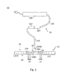
- the high bay light 10 comprises a heat dissipation disk 12, a lighting unit 14, and a driving module 16.
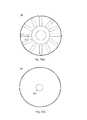
- the heat dissipation disk 12 has a plurality of heat dissipation modules 122 and an accommodating part 124. It also can refer to Fig.2 , it discloses that the shape of the heat dissipation disk 12 is round, and the shape of the plurality of heat dissipation modules 122 is sector. In other embodiment, the heat dissipation disk 12 and the heat dissipation modules 122 can be any shape. In addition, an amount of heat dissipation modules 122 is sixteen. The plurality of heat dissipations modules 122 is assembled each other or formed integrally.
- the accommodating part 124 is connected with the plurality of heat dissipation modules 122, in this embodiment, the accommodating part 124 is configured to a central part of the heat dissipation disk 12.
- the accommodating part 124 further comprises a plurality of voids 1242.
- each the plurality of heat dissipation modules 122 also further comprises a plurality of heat dissipation holes 1224.
- An air flow AF pass through the plurality of heat dissipation holes 1242 and the plurality of voids 1242 for dissipating a heat (not shown) generated from the heat dissipation disk 12, the lighting unit 14 and the driving module 16.
- a heat (not shown) generated from the heat dissipation disk 12, the lighting unit 14 and the driving module 16.
- the plurality of voids 1242 are installed closely to the lighting unit 14, such as central position of the lighting unit 14, the heat mainly generated of the lighting unit 14 can be dissipated quickly.
- the heat dissipation disk 12 can improve a rate of heat dissipation, such as coating or spraying a coating layer (not shown) on the surface of heat dissipation disk 12 or changing a thinness or a diameter of heat dissipation disk.
- the coating layer further comprises a copper powder can dissipate the heat more quickly.
- the lighting unit 14 is configured in the accommodating part 124.
- the lighting unit 14 has a plurality of light emitting diodes 142.
- the light emitting diodes 142 can be arrange as a strip light (refer to Fig.3 (a) ) or a single light (refer to Fig.3 (b) ).
- amount of strip lights is sixteen, and each of the strip lights is consisted of four light emitting diodes 142.
- each of the strip lights can be a single light emitting diode 142.
- Fig.3 (a) amount of strip lights is sixteen, and each of the strip lights is consisted of four light emitting diodes 142. In other embodiment, each of the strip lights can be a single light emitting diode 142.
- the single light can be installed in the central of the lighting unit 14, in this embodiment, the heat dissipation disk 12 can remove the plurality of voids 1242.
- the plurality of light emitting diodes 142 generate a light ray LR.
- the plurality of light emitting diodes 142 is arranged corresponding to the plurality of heat dissipation modules 122. In other word, each of the plurality of light emitting diodes 142 is connected with one of heat dissipation modules 122.
- the lighting unit (14) can comprises a reflective layer (not shown), the reflective layer is configured to back side of light emitting diodes 142 for reflecting the light ray LR.
- the driving module 16 is connected with the lighting unit 14.
- the driving module 16 drives the plurality of light emitting diodes 142 for generating the light ray LR, such as the driving module 16 is consisted with a pair of electrical plug 162, 164, an electric cable 166, a transformers 168, and a connector 1610.
- the electric cable 166 is connected with the electrical plugs 164 and transformers 166, and the electric cable 166 is also connected with the electrical plugs 162 and the connector 1610.
- the connector 1610 is connected to the lighting unit 14.
- the electrical plug 162, 164 can easily to plug-in and plug-out for replacing the transformers 168, if the transformers 168 is broken.
- the electrical plug 162, 164 can be separated or be connected easily and quickly.
- the transformers 168 can convert the alternating current (AC) to a direct current (DC), the direct current can drive the plurality of light emitting diodes 142.
- the electric cable 166 can directly provide for the direct current without converting.
- the pair of electrical plug 162, 164 and the connector 1610 may be provided for waterproofing to prevent to damage the lighting unit 14 or other components.
- FIG. 4 is an explosion diagram of a high bay light in a second embodiment of the present invention.
- the high bay light 10' comprises the lighting unit 14, and the driving module 16 in the first embodiment, but a heat dissipation disk 12' is a little different.
- the heat dissipation disk 12' comprises a plurality of trenches 126 and a plurality of heat pipes 128.
- the plurality of trenches 126 is formed on a side of the plurality of heat dissipation modules 122 for installing configured the plurality of heat pipes 128.
- the amount of plurality of heat pipes 128 can be chosen according to output power of lighting unit 14.
- each the plurality of heat pipes 128 is corresponded to each the plurality of light emitting diodes 142, namely, each heat pipes 128 can directly to dissipate the heat generated by each light emitting diodes 142 independently. In other embodiment, it is not limited condition. It worth to understanding that a platen (not shown) can hide the plurality of heat pipes 128.
- Fig.5 is an explosion diagram of a high bay light in a third embodiment of the present invention.
- the high bay light 10" comprises the heat dissipation disk 12', the lighting unit 14, and the driving module 16 in the second embodiment except for an optical unit 18.
- the optical unit 18 is cover over the accommodating part 124 so as to the light ray LR can pass through.
- the optical unit 18 can protect the lighting unit 14 or change a characterization of light ray LR, such as refraction, diffraction, diffusion, etc.
- the material of optical unit 18 can be a plastic, a glass, etc.
- a plastic assembly (not shown) is combined between the heat dissipation disk 12' and the lighting unit 14.
- the plastic assembly is resistant to water. It can be refer to Fig.8 , a schematic diagram of a high bay light of the present invention.
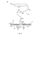
- Fig.6 is an explosion diagram of a high bay light in fourth embodiment of the present invention.
- the high bay light 10' comprises the heat dissipation disk 12', the lighting unit 14, the driving module 16, and the optical unit 18 in the third embodiment except for a suspended unit 20.
- the suspended unit 20 is connected with the heat dissipation disk 12'.
- the suspended unit 20 is suspended from an object (not shown), such as an air pipe, a roof or a ceiling.
- the suspended unit 20 can comprise a holder 202 and a shackle 204.
- the holder 202 is combined with the shackle 204, the holder 202 is gripped the heat dissipation disk 12.
- the driving module 16 is configured between the holder 202 and the heat dissipation disk 12.
- the driving module 16 cam be hided.
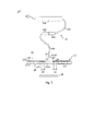
- the high bay light 10" comprises the heat dissipation disk 12', the lighting unit 14, the driving module 16, the optical unit 18, and the suspended unit 20 in the fourth embodiment except for a plurality of heat dissipation pillars 22.
- the plurality of heat dissipation pillars 22 is configured to a back side of heat dissipation disk 12' for dissipating the heat.
- Each the plurality of heat dissipation pillar 22 is corresponded to each the plurality of light emitting diodes 142 or the light emitting diode 1422, namely, each light emitting diodes 142 can directly to dissipate the heat generated by each light emitting diodes 142 or the light emitting diode 1422 independently. In other embodiment, it is not limited condition.
- the heat dissipation pillar 22 can be replaced by a heat dissipation block (not shown).
- a waterproofing material 182 can further install to reach a waterproofing, such as a plastic assembly.
- a plastic assembly is installed at a periphery of optical unit 18, such as O-ring.
- the plastic assembly is resistant to water. It can be refer to Fig.8 , a schematic diagram of a high bay light of the present invention.
Priority Applications (1)
| Application Number | Priority Date | Filing Date | Title |
|---|---|---|---|
| EP15191290.4A EP3159607A1 (de) | 2015-10-23 | 2015-10-23 | Hallenleuchte |
Applications Claiming Priority (1)
| Application Number | Priority Date | Filing Date | Title |
|---|---|---|---|
| EP15191290.4A EP3159607A1 (de) | 2015-10-23 | 2015-10-23 | Hallenleuchte |
Publications (1)
| Publication Number | Publication Date |
|---|---|
| EP3159607A1 true EP3159607A1 (de) | 2017-04-26 |
Family
ID=54360901
Family Applications (1)
| Application Number | Title | Priority Date | Filing Date |
|---|---|---|---|
| EP15191290.4A Withdrawn EP3159607A1 (de) | 2015-10-23 | 2015-10-23 | Hallenleuchte |
Country Status (1)
| Country | Link |
|---|---|
| EP (1) | EP3159607A1 (de) |
Citations (6)
| Publication number | Priority date | Publication date | Assignee | Title |
|---|---|---|---|---|
| US7611264B1 (en) * | 2008-08-28 | 2009-11-03 | Li-Hong Technological Co., Ltd. | LED lamp |
| US20120113640A1 (en) * | 2010-11-05 | 2012-05-10 | Markle Joshua J | Multi-configurable, high luminous output light fixture systems, devices and methods |
| US20120163003A1 (en) * | 2010-12-22 | 2012-06-28 | Lee Ki Un | Light emitting apparatus |
| DE202013100167U1 (de) * | 2012-02-21 | 2013-02-08 | Unity Opto Technology Co., Ltd. | Lampe mit hoher Kühlwirkung |
| US20130176707A1 (en) * | 2012-01-10 | 2013-07-11 | James Audette | Modular LED Space Light |
| WO2015149118A1 (en) * | 2014-04-04 | 2015-10-08 | Outsight Pty Ltd | A lighting system and a method of lighting |
-
2015
- 2015-10-23 EP EP15191290.4A patent/EP3159607A1/de not_active Withdrawn
Patent Citations (6)
| Publication number | Priority date | Publication date | Assignee | Title |
|---|---|---|---|---|
| US7611264B1 (en) * | 2008-08-28 | 2009-11-03 | Li-Hong Technological Co., Ltd. | LED lamp |
| US20120113640A1 (en) * | 2010-11-05 | 2012-05-10 | Markle Joshua J | Multi-configurable, high luminous output light fixture systems, devices and methods |
| US20120163003A1 (en) * | 2010-12-22 | 2012-06-28 | Lee Ki Un | Light emitting apparatus |
| US20130176707A1 (en) * | 2012-01-10 | 2013-07-11 | James Audette | Modular LED Space Light |
| DE202013100167U1 (de) * | 2012-02-21 | 2013-02-08 | Unity Opto Technology Co., Ltd. | Lampe mit hoher Kühlwirkung |
| WO2015149118A1 (en) * | 2014-04-04 | 2015-10-08 | Outsight Pty Ltd | A lighting system and a method of lighting |
Similar Documents
| Publication | Publication Date | Title |
|---|---|---|
| US11617254B2 (en) | Solid state lighting fixtures | |
| US8403533B1 (en) | Adjustable LED module with stationary heat sink | |
| US9068719B2 (en) | Light engines for lighting devices | |
| US8950907B2 (en) | Convertible lighting fixture for multiple light sources | |
| US9285103B2 (en) | Light engines for lighting devices | |
| US8459835B2 (en) | Light emitting diode lamp | |
| US20120099318A1 (en) | Light emitting diode lamp | |
| JP2014099421A (ja) | 安定器内蔵型固体照明装置 | |
| KR20090091753A (ko) | 조명 조립체 및 조명 조립체용 부품 | |
| TW201246624A (en) | Light emitting diode (LED) module | |
| KR101201490B1 (ko) | 친환경 염료감응 태양전지를 활용한 루버형 엘이디 조명 기구 | |
| US10132487B2 (en) | Luminaire heat sink | |
| AU2016247786B2 (en) | Luminaire housing | |
| US20120099319A1 (en) | Light emitting diode lamp | |
| US10371368B2 (en) | Canopy light system | |
| EP2851608A1 (de) | LED-Lampe | |
| EP3159607A1 (de) | Hallenleuchte | |
| KR101177442B1 (ko) | 조명 장치 | |
| US9797574B2 (en) | Light-emitting diode obstruction light | |
| US9644829B2 (en) | Systems and methods for providing a field repairable light fixture with a housing that dissipates heat | |
| JP6172682B2 (ja) | 照明器具設備 | |
| WO2015036805A1 (en) | Modular lighting device adapted for retrofitting existing lighting units | |
| KR20160064575A (ko) | 엘이디 조명 장치 | |
| TWI565910B (zh) | LED explosion - proof lamps | |
| US20140307451A1 (en) | Outdoor led lighting device structure with good characteristics of thermal dissipation and waterproof |
Legal Events
| Date | Code | Title | Description |
|---|---|---|---|
| PUAI | Public reference made under article 153(3) epc to a published international application that has entered the european phase |
Free format text: ORIGINAL CODE: 0009012 |
|
| AK | Designated contracting states |
Kind code of ref document: A1 Designated state(s): AL AT BE BG CH CY CZ DE DK EE ES FI FR GB GR HR HU IE IS IT LI LT LU LV MC MK MT NL NO PL PT RO RS SE SI SK SM TR |
|
| AX | Request for extension of the european patent |
Extension state: BA ME |
|
| 17P | Request for examination filed |
Effective date: 20171026 |
|
| RBV | Designated contracting states (corrected) |
Designated state(s): AL AT BE BG CH CY CZ DE DK EE ES FI FR GB GR HR HU IE IS IT LI LT LU LV MC MK MT NL NO PL PT RO RS SE SI SK SM TR |
|
| 17Q | First examination report despatched |
Effective date: 20180124 |
|
| STAA | Information on the status of an ep patent application or granted ep patent |
Free format text: STATUS: THE APPLICATION IS DEEMED TO BE WITHDRAWN |
|
| 18D | Application deemed to be withdrawn |
Effective date: 20180605 |