EP3159543A1 - Gear pump - Google Patents
Gear pump Download PDFInfo
- Publication number
- EP3159543A1 EP3159543A1 EP16185840.2A EP16185840A EP3159543A1 EP 3159543 A1 EP3159543 A1 EP 3159543A1 EP 16185840 A EP16185840 A EP 16185840A EP 3159543 A1 EP3159543 A1 EP 3159543A1
- Authority
- EP
- European Patent Office
- Prior art keywords
- pump
- gear
- rotor
- electrical
- fuel
- Prior art date
- Legal status (The legal status is an assumption and is not a legal conclusion. Google has not performed a legal analysis and makes no representation as to the accuracy of the status listed.)
- Granted
Links
Images


Classifications
-
- F—MECHANICAL ENGINEERING; LIGHTING; HEATING; WEAPONS; BLASTING
- F04—POSITIVE - DISPLACEMENT MACHINES FOR LIQUIDS; PUMPS FOR LIQUIDS OR ELASTIC FLUIDS
- F04C—ROTARY-PISTON, OR OSCILLATING-PISTON, POSITIVE-DISPLACEMENT MACHINES FOR LIQUIDS; ROTARY-PISTON, OR OSCILLATING-PISTON, POSITIVE-DISPLACEMENT PUMPS
- F04C14/00—Control of, monitoring of, or safety arrangements for, machines, pumps or pumping installations
- F04C14/08—Control of, monitoring of, or safety arrangements for, machines, pumps or pumping installations characterised by varying the rotational speed
-
- F—MECHANICAL ENGINEERING; LIGHTING; HEATING; WEAPONS; BLASTING
- F04—POSITIVE - DISPLACEMENT MACHINES FOR LIQUIDS; PUMPS FOR LIQUIDS OR ELASTIC FLUIDS
- F04C—ROTARY-PISTON, OR OSCILLATING-PISTON, POSITIVE-DISPLACEMENT MACHINES FOR LIQUIDS; ROTARY-PISTON, OR OSCILLATING-PISTON, POSITIVE-DISPLACEMENT PUMPS
- F04C29/00—Component parts, details or accessories of pumps or pumping installations, not provided for in groups F04C18/00 - F04C28/00
- F04C29/0042—Driving elements, brakes, couplings, transmissions specially adapted for pumps
- F04C29/0085—Prime movers
-
- F—MECHANICAL ENGINEERING; LIGHTING; HEATING; WEAPONS; BLASTING
- F02—COMBUSTION ENGINES; HOT-GAS OR COMBUSTION-PRODUCT ENGINE PLANTS
- F02C—GAS-TURBINE PLANTS; AIR INTAKES FOR JET-PROPULSION PLANTS; CONTROLLING FUEL SUPPLY IN AIR-BREATHING JET-PROPULSION PLANTS
- F02C7/00—Features, components parts, details or accessories, not provided for in, or of interest apart form groups F02C1/00 - F02C6/00; Air intakes for jet-propulsion plants
- F02C7/22—Fuel supply systems
- F02C7/236—Fuel delivery systems comprising two or more pumps
-
- F—MECHANICAL ENGINEERING; LIGHTING; HEATING; WEAPONS; BLASTING
- F04—POSITIVE - DISPLACEMENT MACHINES FOR LIQUIDS; PUMPS FOR LIQUIDS OR ELASTIC FLUIDS
- F04C—ROTARY-PISTON, OR OSCILLATING-PISTON, POSITIVE-DISPLACEMENT MACHINES FOR LIQUIDS; ROTARY-PISTON, OR OSCILLATING-PISTON, POSITIVE-DISPLACEMENT PUMPS
- F04C11/00—Combinations of two or more machines or pumps, each being of rotary-piston or oscillating-piston type; Pumping installations
- F04C11/008—Enclosed motor pump units
-
- F—MECHANICAL ENGINEERING; LIGHTING; HEATING; WEAPONS; BLASTING
- F04—POSITIVE - DISPLACEMENT MACHINES FOR LIQUIDS; PUMPS FOR LIQUIDS OR ELASTIC FLUIDS
- F04C—ROTARY-PISTON, OR OSCILLATING-PISTON, POSITIVE-DISPLACEMENT MACHINES FOR LIQUIDS; ROTARY-PISTON, OR OSCILLATING-PISTON, POSITIVE-DISPLACEMENT PUMPS
- F04C14/00—Control of, monitoring of, or safety arrangements for, machines, pumps or pumping installations
- F04C14/28—Safety arrangements; Monitoring
-
- F—MECHANICAL ENGINEERING; LIGHTING; HEATING; WEAPONS; BLASTING
- F04—POSITIVE - DISPLACEMENT MACHINES FOR LIQUIDS; PUMPS FOR LIQUIDS OR ELASTIC FLUIDS
- F04C—ROTARY-PISTON, OR OSCILLATING-PISTON, POSITIVE-DISPLACEMENT MACHINES FOR LIQUIDS; ROTARY-PISTON, OR OSCILLATING-PISTON, POSITIVE-DISPLACEMENT PUMPS
- F04C15/00—Component parts, details or accessories of machines, pumps or pumping installations, not provided for in groups F04C2/00 - F04C14/00
- F04C15/0057—Driving elements, brakes, couplings, transmission specially adapted for machines or pumps
- F04C15/008—Prime movers
-
- F—MECHANICAL ENGINEERING; LIGHTING; HEATING; WEAPONS; BLASTING
- F04—POSITIVE - DISPLACEMENT MACHINES FOR LIQUIDS; PUMPS FOR LIQUIDS OR ELASTIC FLUIDS
- F04C—ROTARY-PISTON, OR OSCILLATING-PISTON, POSITIVE-DISPLACEMENT MACHINES FOR LIQUIDS; ROTARY-PISTON, OR OSCILLATING-PISTON, POSITIVE-DISPLACEMENT PUMPS
- F04C15/00—Component parts, details or accessories of machines, pumps or pumping installations, not provided for in groups F04C2/00 - F04C14/00
- F04C15/0096—Heating; Cooling
-
- F—MECHANICAL ENGINEERING; LIGHTING; HEATING; WEAPONS; BLASTING
- F04—POSITIVE - DISPLACEMENT MACHINES FOR LIQUIDS; PUMPS FOR LIQUIDS OR ELASTIC FLUIDS
- F04C—ROTARY-PISTON, OR OSCILLATING-PISTON, POSITIVE-DISPLACEMENT MACHINES FOR LIQUIDS; ROTARY-PISTON, OR OSCILLATING-PISTON, POSITIVE-DISPLACEMENT PUMPS
- F04C2/00—Rotary-piston machines or pumps
- F04C2/08—Rotary-piston machines or pumps of intermeshing-engagement type, i.e. with engagement of co-operating members similar to that of toothed gearing
-
- F—MECHANICAL ENGINEERING; LIGHTING; HEATING; WEAPONS; BLASTING
- F04—POSITIVE - DISPLACEMENT MACHINES FOR LIQUIDS; PUMPS FOR LIQUIDS OR ELASTIC FLUIDS
- F04C—ROTARY-PISTON, OR OSCILLATING-PISTON, POSITIVE-DISPLACEMENT MACHINES FOR LIQUIDS; ROTARY-PISTON, OR OSCILLATING-PISTON, POSITIVE-DISPLACEMENT PUMPS
- F04C2/00—Rotary-piston machines or pumps
- F04C2/08—Rotary-piston machines or pumps of intermeshing-engagement type, i.e. with engagement of co-operating members similar to that of toothed gearing
- F04C2/082—Details specially related to intermeshing engagement type machines or pumps
- F04C2/084—Toothed wheels
-
- F—MECHANICAL ENGINEERING; LIGHTING; HEATING; WEAPONS; BLASTING
- F04—POSITIVE - DISPLACEMENT MACHINES FOR LIQUIDS; PUMPS FOR LIQUIDS OR ELASTIC FLUIDS
- F04C—ROTARY-PISTON, OR OSCILLATING-PISTON, POSITIVE-DISPLACEMENT MACHINES FOR LIQUIDS; ROTARY-PISTON, OR OSCILLATING-PISTON, POSITIVE-DISPLACEMENT PUMPS
- F04C2/00—Rotary-piston machines or pumps
- F04C2/08—Rotary-piston machines or pumps of intermeshing-engagement type, i.e. with engagement of co-operating members similar to that of toothed gearing
- F04C2/10—Rotary-piston machines or pumps of intermeshing-engagement type, i.e. with engagement of co-operating members similar to that of toothed gearing of internal-axis type with the outer member having more teeth or tooth-equivalents, e.g. rollers, than the inner member
- F04C2/102—Rotary-piston machines or pumps of intermeshing-engagement type, i.e. with engagement of co-operating members similar to that of toothed gearing of internal-axis type with the outer member having more teeth or tooth-equivalents, e.g. rollers, than the inner member the two members rotating simultaneously around their respective axes
-
- F—MECHANICAL ENGINEERING; LIGHTING; HEATING; WEAPONS; BLASTING
- F04—POSITIVE - DISPLACEMENT MACHINES FOR LIQUIDS; PUMPS FOR LIQUIDS OR ELASTIC FLUIDS
- F04C—ROTARY-PISTON, OR OSCILLATING-PISTON, POSITIVE-DISPLACEMENT MACHINES FOR LIQUIDS; ROTARY-PISTON, OR OSCILLATING-PISTON, POSITIVE-DISPLACEMENT PUMPS
- F04C2/00—Rotary-piston machines or pumps
- F04C2/08—Rotary-piston machines or pumps of intermeshing-engagement type, i.e. with engagement of co-operating members similar to that of toothed gearing
- F04C2/12—Rotary-piston machines or pumps of intermeshing-engagement type, i.e. with engagement of co-operating members similar to that of toothed gearing of other than internal-axis type
- F04C2/14—Rotary-piston machines or pumps of intermeshing-engagement type, i.e. with engagement of co-operating members similar to that of toothed gearing of other than internal-axis type with toothed rotary pistons
-
- F—MECHANICAL ENGINEERING; LIGHTING; HEATING; WEAPONS; BLASTING
- F04—POSITIVE - DISPLACEMENT MACHINES FOR LIQUIDS; PUMPS FOR LIQUIDS OR ELASTIC FLUIDS
- F04C—ROTARY-PISTON, OR OSCILLATING-PISTON, POSITIVE-DISPLACEMENT MACHINES FOR LIQUIDS; ROTARY-PISTON, OR OSCILLATING-PISTON, POSITIVE-DISPLACEMENT PUMPS
- F04C2210/00—Fluid
- F04C2210/10—Fluid working
- F04C2210/1044—Fuel
-
- F—MECHANICAL ENGINEERING; LIGHTING; HEATING; WEAPONS; BLASTING
- F04—POSITIVE - DISPLACEMENT MACHINES FOR LIQUIDS; PUMPS FOR LIQUIDS OR ELASTIC FLUIDS
- F04C—ROTARY-PISTON, OR OSCILLATING-PISTON, POSITIVE-DISPLACEMENT MACHINES FOR LIQUIDS; ROTARY-PISTON, OR OSCILLATING-PISTON, POSITIVE-DISPLACEMENT PUMPS
- F04C2240/00—Components
- F04C2240/40—Electric motor
-
- F—MECHANICAL ENGINEERING; LIGHTING; HEATING; WEAPONS; BLASTING
- F04—POSITIVE - DISPLACEMENT MACHINES FOR LIQUIDS; PUMPS FOR LIQUIDS OR ELASTIC FLUIDS
- F04C—ROTARY-PISTON, OR OSCILLATING-PISTON, POSITIVE-DISPLACEMENT MACHINES FOR LIQUIDS; ROTARY-PISTON, OR OSCILLATING-PISTON, POSITIVE-DISPLACEMENT PUMPS
- F04C2270/00—Control; Monitoring or safety arrangements
- F04C2270/05—Speed
- F04C2270/051—Controlled or regulated
Definitions
- the present invention relates to a gear pump, and particularly, but not exclusively, to a high pressure gear pump of an aero-engine fuel pumping unit.
- a typical fuel pumping unit for an aero-engine comprises a low pressure (LP) pump operable to draw fuel from a fuel tank, and supplying the fuel at boosted pressure to the inlet of a high pressure (HP) pump.
- LP low pressure
- HP high pressure
- the inter-stage flow between LP and HP pumps is typically used to cool engine lubrication oil in a fuel/oil heat exchanger.
- the LP pump comprises a centrifugal impeller pump whilst the HP pump comprises a positive displacement pump in the form of a twin pinion gear pump.
- the pumps are generally driven from a shaft on the engine accessory gearbox and therefore have a fixed speed relationship with engine running speed. A rotating seal is typically required to avoid leakage around the input drive shaft to the gear pump.
- Figure 1 shows schematically a conventional twin pinion gear arrangement with first 2 and second 4 pinion gears mounted on parallel first 6 and second 8 gear shafts, the gears meshing at region R.
- a positive displacement pump such as a gear pump, is typically configured to provide sufficient flow at the maximum take-off or the windmill-relight design points of an aero-engine.
- the pump generally only needs to provide a small fraction of this flow under normal operation, with the excess flow being re-circulated.
- the present invention provides a gear pump having:
- pump speed can be varied independently of engine speed so that less flow has to be recirculated which in turn reduces the heating of the pumped fluid.
- This is of particular benefit in the context of an aero-engine fuel pump, as the fuel then has additional heat sink capability to cool other parts of the engine.
- the electrical motors avoid the need for a rotating seal, but they can be integrated with other parts of the pump to form a compact pump arrangement.
- the pumped fluid can be used for cooling the motors.
- the present invention provides a fuel pumping unit for an aero-engine (such as a gas turbine engine), the unit having a low pressure pump and a high pressure pump, the low pressure pump supplying fuel at a raised pressure to the high pressure pump for onward supply to a fuel metering unit of the engine, wherein the high pressure pump is a pump according to the first aspect.
- the present invention provides an aero-engine (such as a gas turbine engine) having a fuel pumping unit according to the second aspect.
- first and second gears are pinion gears.
- the gears are non-magnetic.
- the profiles of the teeth of the gears can be optimised for pumping low lubricity fluid such as fuel.
- the electrical motors may be brushless electrical motors.
- first rotor and the first gear may be mounted, axially spaced from each other, on a first gear shaft
- the second rotor and the second gear may be mounted, axially spaced from each other, on a second gear shaft.
- the gear shafts can be parallel to each other.
- the first and second rotors can be on the same side of the meshing gears.
- the rotors can be on opposite sides of the meshing gears.
- cores of the first and second stators can be formed as a unitary body, facilitating a more compact pump arrangement.
- this does not affect the separateness of the first and second coil windings and hence the independence of the gears.
- the first and second electrical power circuits may each include a respective variable frequency motor drive.
- Each variable frequency motor drive typically comprises inverter power electronics.
- the pump may be configured such that the electrical motors are cooled by a cooling flow formed from a flow of the pumped fluid.
- the electrical motors may be fully immersed in the fluid. Locating the motors in a fuel flooded part of the pump helps to avoid a need for a rotating seal.
- the pump may further have a control unit which controls the power provided by the first and second electrical power circuits to run the pump at different speeds.
- a control unit may further vary the relative amounts of power provided by the circuits so that varying amounts of mechanical power can be transferred between the gears. This allows a desired amount of gear-to-gear interface sealing to be attained.
- the control unit can run the pump by driving just the other gear, thereby improving redundancy in the pump.
- the control unit may further compare the power provided by the circuits with a reference power characteristic (e.g. power against pump speed) to monitor the health of the pump.
- a ducted fan gas turbine engine incorporating the invention is generally indicated at 10 and has a principal and rotational axis X-X.
- the engine comprises, in axial flow series, an air intake 11, a propulsive fan 12, an intermediate pressure compressor 13, a high-pressure compressor 14, combustion equipment 15, a high-pressure turbine 16, an intermediate pressure turbine 17, a low-pressure turbine 18 and a core engine exhaust nozzle 19.
- a nacelle 21 generally surrounds the engine 10 and defines the intake 11, a bypass duct 22 and a bypass exhaust nozzle 23.
- air entering the intake 11 is accelerated by the fan 12 to produce two air flows: a first air flow A into the intermediate-pressure compressor 13 and a second air flow B which passes through the bypass duct 22 to provide propulsive thrust.
- the intermediate-pressure compressor 13 compresses the air flow A directed into it before delivering that air to the high-pressure compressor 14 where further compression takes place.
- the compressed air exhausted from the high-pressure compressor 14 is directed into the combustion equipment 15 where it is mixed with fuel and the mixture combusted.
- the resultant hot combustion products then expand through, and thereby drive the high, intermediate and low-pressure turbines 16, 17, 18 before being exhausted through the nozzle 19 to provide additional propulsive thrust.
- the high, intermediate and low-pressure turbines respectively drive the high and intermediate-pressure compressors 14, 13 and the fan 12 by suitable interconnecting shafts.
- the engine has a fuel pumping unit (not shown in Figure 2 ) which receives fuel from one or more local pumps associated with respective aircraft wing fuel tanks, and supplies pressurised fuel to a fuel metering unit of the engine. The metered fuel is then sent to the burners of the combustion equipment 15.
- a fuel pumping unit (not shown in Figure 2 ) which receives fuel from one or more local pumps associated with respective aircraft wing fuel tanks, and supplies pressurised fuel to a fuel metering unit of the engine. The metered fuel is then sent to the burners of the combustion equipment 15.
- the pumping unit has an LP and an HP pump.
- the LP pump can be a centrifugal pump.
- the HP pump can be a twin pinion gear pump, as shown schematically in the cross-section of Figure 3 .
- An example motor arrangement in an end view of the pump from direction A is then shown schematically in Figure 4 .
- the HP pump has first 30 and second 32 non-magnetic, pinion gears respectively mounted on parallel first 34 and second 36 gear shafts, which are held in hydraulic journal bearing blocks 38.
- the gears mesh at region R.
- the first gear is driven by a first brushless electrical motor having a first rotor 40, a first stator 42 and first coil windings 44
- the second gear is driven by a second brushless electrical motor having a second rotor 46, a second stator 48 and second coil windings 50.
- the rotors 40, 46 are axially spaced from their respective pinion gears 30, 32 on their respective gear shafts 34, 36.
- a housing 52 surrounds the pinion gears 30, 32, shafts 34, 36 and electrical motors.
- the two motors are on the same side of the meshing pinion gears 30, 32.
- the first 44 and second 50 coil windings are energised by respective and separate first and second electrical power circuits (not shown) e.g. comprising inverter power electronics. This allows the pinion gears 30, 32 to be driven independently of each other.
- the profile of the gear teeth can be optimised for pumping low lubricity aero-engine fuel.
- a fraction of mechanical power can be transferred between the two gears to attain a desired amount of gear-to-gear interface sealing.
- frictional losses and wear of the gear flanks can be reduced by keeping this transfer to a minimum.
- the pump can have a control unit (not shown) which controls the power provided by the electrical power circuits to run the pump at different speeds.
- the pump speed can thus be varied independently of engine speed so that less flow has to be recirculated which in turn reduces the heating of the pumped fuel, which then has an enhanced heat sink capacity.
- the control unit may further vary the balance of power provided via the two electrical motors so that an optimum amount of power is transferred mechanically via the gear teeth whilst a desired gear-to-gear interface sealing performance is attained.
- the control unit can characterise the required amount of power against pump rotational speed.
- the control of the electrical power circuits can be used as a continuous (or periodic) monitor of the required power to the pump, with a change from the original characterisation indicating pump degradation. More generally, monitoring the power required to drive the pump at different speeds can be used to provide pump prognostics as an indicator of a change in the pumped fluid or mechanical degradation of the pump.
- the use of electrical motors to drive the pump facilitates a compact pump configuration, and avoids a need to provide a rotating seal to pass mechanical drive through the housing 52.
- the pump can avoid a need to seal the rotor ring from the impeller.
- the electrical motor can be fully immersed in the pumped fuel.
- the electrical motors may be fully immersed in the fluid.
- the pump may be configured such that the electrical motors are cooled by a cooling flow formed from a flow of the pumped fuel.
- the fuel is already at a raised pressure on entry into the pump, there should be no undissolved air within the fuel. Accordingly, the therefore the windings 44, 50 are not exposed to air, which reduces the possibility of electrical breakdown within the windings and avoids a need for them to be fully encapsulated.
- Figure 5 shows schematically a cross-section of a variant twin pinion gear pump.
- the two electrical motors are on opposite sides of the meshing pinion gears 30, 32.
- the stators 42, 48 are thus formed as separate bodies which fully surround the rotors.
- Such a variant can allow the diameters of the motors to be increased, thereby enabling an increase in power from the motors.
- the pump may have other applications, particularly where fault tolerance is advantageous.
- the pump may be used for oil pumping and/or in non-aerospace applications.
- the electrical motors described above are switched reluctance motors, but types of motor may be used, such as permanent magnet or induction type. Accordingly, the exemplary embodiments of the invention set forth above are considered to be illustrative and not limiting.
Landscapes
- Engineering & Computer Science (AREA)
- Mechanical Engineering (AREA)
- General Engineering & Computer Science (AREA)
- Chemical & Material Sciences (AREA)
- Combustion & Propulsion (AREA)
- Rotary Pumps (AREA)
Abstract
Description
- The present invention relates to a gear pump, and particularly, but not exclusively, to a high pressure gear pump of an aero-engine fuel pumping unit.
- A typical fuel pumping unit for an aero-engine comprises a low pressure (LP) pump operable to draw fuel from a fuel tank, and supplying the fuel at boosted pressure to the inlet of a high pressure (HP) pump. The inter-stage flow between LP and HP pumps is typically used to cool engine lubrication oil in a fuel/oil heat exchanger.
- Commonly, the LP pump comprises a centrifugal impeller pump whilst the HP pump comprises a positive displacement pump in the form of a twin pinion gear pump. The pumps are generally driven from a shaft on the engine accessory gearbox and therefore have a fixed speed relationship with engine running speed. A rotating seal is typically required to avoid leakage around the input drive shaft to the gear pump.
-
Figure 1 shows schematically a conventional twin pinion gear arrangement with first 2 and second 4 pinion gears mounted on parallel first 6 and second 8 gear shafts, the gears meshing at region R. - A positive displacement pump, such as a gear pump, is typically configured to provide sufficient flow at the maximum take-off or the windmill-relight design points of an aero-engine. However, the pump generally only needs to provide a small fraction of this flow under normal operation, with the excess flow being re-circulated.
- It would be desirable to be able to vary the speed of a positive displacement gear pump during different parts of a flight cycle to reduce heat rejection into the fuel and also to reduce pump wear.
- It would also be desirable to be able to avoid the need for a rotating seal around an input drive shaft to the gear pump.
- Accordingly, in a first aspect, the present invention provides a gear pump having:
- first and second meshing gears for pumping a fluid;
- a first electrical motor having a first rotor, a first stator and first coil windings; and
- a second electrical motor having a second rotor, a second stator and second coil windings;
- wherein the first rotor is operatively connected to the first gear and the second rotor is operatively connected to the second gear such that each gear is rotated by its respective rotor; and
- wherein the first and second coil windings are energised by respective and separate first and second electrical power circuits such that the first and second meshing gears can be driven independently of each other.
- Advantageously, as the pump is driven by an electrical motor, pump speed can be varied independently of engine speed so that less flow has to be recirculated which in turn reduces the heating of the pumped fluid. This is of particular benefit in the context of an aero-engine fuel pump, as the fuel then has additional heat sink capability to cool other parts of the engine.
- Moreover, not only can the electrical motors avoid the need for a rotating seal, but they can be integrated with other parts of the pump to form a compact pump arrangement.
- Additionally, the pumped fluid can be used for cooling the motors.
- In a second aspect, the present invention provides a fuel pumping unit for an aero-engine (such as a gas turbine engine), the unit having a low pressure pump and a high pressure pump, the low pressure pump supplying fuel at a raised pressure to the high pressure pump for onward supply to a fuel metering unit of the engine, wherein the high pressure pump is a pump according to the first aspect.
- In a third aspect, the present invention provides an aero-engine (such as a gas turbine engine) having a fuel pumping unit according to the second aspect.
- Optional features of the invention will now be set out. These are applicable singly or in any combination with any aspect of the invention.
- Typically the first and second gears are pinion gears.
- Typically, the gears are non-magnetic. Moreover the profiles of the teeth of the gears can be optimised for pumping low lubricity fluid such as fuel.
- The electrical motors may be brushless electrical motors.
- Conveniently, the first rotor and the first gear may be mounted, axially spaced from each other, on a first gear shaft, and the second rotor and the second gear may be mounted, axially spaced from each other, on a second gear shaft. The gear shafts can be parallel to each other.
- Conveniently, the first and second rotors can be on the same side of the meshing gears. However, this does not exclude that the rotors can be on opposite sides of the meshing gears. Particularly when the rotor are on the same side, cores of the first and second stators can be formed as a unitary body, facilitating a more compact pump arrangement. However, this does not affect the separateness of the first and second coil windings and hence the independence of the gears.
- The first and second electrical power circuits may each include a respective variable frequency motor drive. Each variable frequency motor drive typically comprises inverter power electronics.
- The pump may be configured such that the electrical motors are cooled by a cooling flow formed from a flow of the pumped fluid.
- The electrical motors may be fully immersed in the fluid. Locating the motors in a fuel flooded part of the pump helps to avoid a need for a rotating seal.
- The pump may further have a control unit which controls the power provided by the first and second electrical power circuits to run the pump at different speeds. Such a control unit may further vary the relative amounts of power provided by the circuits so that varying amounts of mechanical power can be transferred between the gears. This allows a desired amount of gear-to-gear interface sealing to be attained. Also, if the motors or circuit of one of the gears fails or develops a fault, the control unit can run the pump by driving just the other gear, thereby improving redundancy in the pump. The control unit may further compare the power provided by the circuits with a reference power characteristic (e.g. power against pump speed) to monitor the health of the pump.
- Embodiments of the invention will now be described by way of example with reference to the accompanying drawings in which:
-
Figure 1 shows schematically a conventional twin pinion gear arrangement; -
Figure 2 shows a longitudinal cross-section through a ducted fan gas turbine engine; -
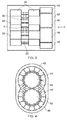
Figure 3 shows schematically a cross-section of a twin pinion gear pump; -
Figure 4 shows schematically an example motor arrangement in an end view of the pump of -
Figure 3 from direction A; and -
Figure 5 shows schematically a cross-section of a variant twin pinion gear pump having a different motor arrangement. - With reference to
Figure 2 , a ducted fan gas turbine engine incorporating the invention is generally indicated at 10 and has a principal and rotational axis X-X. The engine comprises, in axial flow series, anair intake 11, apropulsive fan 12, anintermediate pressure compressor 13, a high-pressure compressor 14,combustion equipment 15, a high-pressure turbine 16, anintermediate pressure turbine 17, a low-pressure turbine 18 and a coreengine exhaust nozzle 19. Anacelle 21 generally surrounds theengine 10 and defines theintake 11, abypass duct 22 and abypass exhaust nozzle 23. - During operation, air entering the
intake 11 is accelerated by thefan 12 to produce two air flows: a first air flow A into the intermediate-pressure compressor 13 and a second air flow B which passes through thebypass duct 22 to provide propulsive thrust. The intermediate-pressure compressor 13 compresses the air flow A directed into it before delivering that air to the high-pressure compressor 14 where further compression takes place. - The compressed air exhausted from the high-
pressure compressor 14 is directed into thecombustion equipment 15 where it is mixed with fuel and the mixture combusted. The resultant hot combustion products then expand through, and thereby drive the high, intermediate and low-pressure turbines nozzle 19 to provide additional propulsive thrust. The high, intermediate and low-pressure turbines respectively drive the high and intermediate-pressure compressors fan 12 by suitable interconnecting shafts. - The engine has a fuel pumping unit (not shown in
Figure 2 ) which receives fuel from one or more local pumps associated with respective aircraft wing fuel tanks, and supplies pressurised fuel to a fuel metering unit of the engine. The metered fuel is then sent to the burners of thecombustion equipment 15. - The pumping unit has an LP and an HP pump. The LP pump can be a centrifugal pump.
- The HP pump, by contrast, can be a twin pinion gear pump, as shown schematically in the cross-section of
Figure 3 . An example motor arrangement in an end view of the pump from direction A is then shown schematically inFigure 4 . - The HP pump has first 30 and second 32 non-magnetic, pinion gears respectively mounted on parallel first 34 and second 36 gear shafts, which are held in hydraulic journal bearing blocks 38. The gears mesh at region R. The first gear is driven by a first brushless electrical motor having a
first rotor 40, afirst stator 42 andfirst coil windings 44, and the second gear is driven by a second brushless electrical motor having asecond rotor 46, asecond stator 48 andsecond coil windings 50. Therotors respective gear shafts housing 52 surrounds the pinion gears 30, 32,shafts - The two motors are on the same side of the meshing pinion gears 30, 32. This allows the
stators Figure 4 . Nonetheless thecoil windings - The first 44 and second 50 coil windings are energised by respective and separate first and second electrical power circuits (not shown) e.g. comprising inverter power electronics. This allows the pinion gears 30, 32 to be driven independently of each other.
- Thus no single fault should cause both gears to fail. In particular, if a motor phase winding(s) is not providing electrical power, due to e.g. failure of inverter power electronics or a failure within the motor, the pump can revert to a gear-meshing mechanical arrangement in which one gear is driven by the other gear. The drive requirements of the faulty motor-driven gear may be augmented mechanically via the remaining operational motor-driven gear. This provides a level of redundancy which is beneficial in an aero-engine fuel pump.
- The profile of the gear teeth can be optimised for pumping low lubricity aero-engine fuel. With each of the pump gears independently driven, under normal operation, a fraction of mechanical power can be transferred between the two gears to attain a desired amount of gear-to-gear interface sealing. However, frictional losses and wear of the gear flanks can be reduced by keeping this transfer to a minimum.
- The pump can have a control unit (not shown) which controls the power provided by the electrical power circuits to run the pump at different speeds. The pump speed can thus be varied independently of engine speed so that less flow has to be recirculated which in turn reduces the heating of the pumped fuel, which then has an enhanced heat sink capacity.
- The control unit may further vary the balance of power provided via the two electrical motors so that an optimum amount of power is transferred mechanically via the gear teeth whilst a desired gear-to-gear interface sealing performance is attained. Moreover, as the pump is driven, the control unit can characterise the required amount of power against pump rotational speed. In this way, the control of the electrical power circuits can be used as a continuous (or periodic) monitor of the required power to the pump, with a change from the original characterisation indicating pump degradation. More generally, monitoring the power required to drive the pump at different speeds can be used to provide pump prognostics as an indicator of a change in the pumped fluid or mechanical degradation of the pump.
- As well as the above advantages, the use of electrical motors to drive the pump facilitates a compact pump configuration, and avoids a need to provide a rotating seal to pass mechanical drive through the
housing 52. - Moreover, the pump can avoid a need to seal the rotor ring from the impeller. Indeed, the electrical motor can be fully immersed in the pumped fuel. Indeed, the electrical motors may be fully immersed in the fluid.
- Conveniently, the pump may be configured such that the electrical motors are cooled by a cooling flow formed from a flow of the pumped fuel. As the fuel is already at a raised pressure on entry into the pump, there should be no undissolved air within the fuel. Accordingly, the therefore the
windings -
Figure 5 shows schematically a cross-section of a variant twin pinion gear pump. In the variant, the two electrical motors are on opposite sides of the meshing pinion gears 30, 32. Thestators - While the invention has been described in conjunction with the exemplary embodiments described above, many equivalent modifications and variations will be apparent to those skilled in the art when given this disclosure. For example, although descried above in relation to a high pressure pump of an aero-engine fuel pumping unit, the pump may have other applications, particularly where fault tolerance is advantageous. Thus the pump may be used for oil pumping and/or in non-aerospace applications. Moreover, the electrical motors described above are switched reluctance motors, but types of motor may be used, such as permanent magnet or induction type. Accordingly, the exemplary embodiments of the invention set forth above are considered to be illustrative and not limiting.
Claims (8)
- A gear pump having:first (30) and second (32) meshing gears for pumping a fluid;a first electrical motor having a first rotor (40), a first stator (42) and first coil windings (44); anda second electrical motor having a second rotor (46), a second stator (48) and second coil windings (50);wherein the first rotor is operatively connected to the first gear and the second rotor is operatively connected to the second gear such that each gear is rotated by its respective rotor;wherein the first and second coil windings are energised by respective and separate first and second electrical power circuits such that the first and second meshing gears can be driven independently of each other;wherein the first rotor and the first gear are mounted, axially spaced from each other, on a first gear shaft (34), and the second rotor and the second gear are mounted, axially spaced from each other, on a second gear shaft (36); andwherein the pump is configured such that the electrical motors are cooled by a cooling flow formed from a flow of the pumped fluid.
- A pump according to claim 1, wherein the first and second electrical power circuits each include a respective variable frequency motor drive.
- A pump according to claim 1 or 2, wherein the electrical motors are fully immersed in the fluid.
- A pump according to any one of the previous claims, further having a control unit which controls the power provided by the first and second electrical power circuits to run the pump at different speeds.
- A pump according to claim 4, wherein the control unit further varies the relative amounts of power provided by the circuits so that varying amounts of mechanical power can be transferred between the gears.
- A pump according to claim 4 or 5, wherein the control unit further compares the power provided by the circuits with a reference power characteristic to monitor the health of the pump.
- A fuel pumping unit for an aero-engine, the unit having a low pressure pump and a high pressure pump, the low pressure pump supplying fuel at a raised pressure to the high pressure pump for onward supply to a fuel metering unit of the engine, wherein the high pressure pump is a pump according to any one of the previous claims.
- An aero-engine having a fuel pumping unit according to claim 7.
Applications Claiming Priority (1)
| Application Number | Priority Date | Filing Date | Title |
|---|---|---|---|
| GBGB1518619.0A GB201518619D0 (en) | 2015-10-21 | 2015-10-21 | Gear Pump |
Publications (2)
| Publication Number | Publication Date |
|---|---|
| EP3159543A1 true EP3159543A1 (en) | 2017-04-26 |
| EP3159543B1 EP3159543B1 (en) | 2023-10-04 |
Family
ID=55131379
Family Applications (1)
| Application Number | Title | Priority Date | Filing Date |
|---|---|---|---|
| EP16185840.2A Active EP3159543B1 (en) | 2015-10-21 | 2016-08-26 | Gear pump |
Country Status (3)
| Country | Link |
|---|---|
| US (1) | US10174760B2 (en) |
| EP (1) | EP3159543B1 (en) |
| GB (1) | GB201518619D0 (en) |
Families Citing this family (4)
| Publication number | Priority date | Publication date | Assignee | Title |
|---|---|---|---|---|
| FR3106625B1 (en) | 2020-01-27 | 2022-11-04 | Safran Helicopter Engines | Aircraft engine fuel system |
| JP7623786B2 (en) | 2020-02-14 | 2025-01-29 | 川崎重工業株式会社 | Gas Turbine Engine |
| US12116899B2 (en) | 2021-12-17 | 2024-10-15 | Rolls-Royce Plc | Variable speed pumping system with electric pump motor generator |
| GB202319533D0 (en) * | 2023-12-19 | 2024-01-31 | Rolls Royce Plc | Positive displacement pump system |
Citations (3)
| Publication number | Priority date | Publication date | Assignee | Title |
|---|---|---|---|---|
| GB2523196A (en) * | 2014-02-18 | 2015-08-19 | Rolls Royce Controls & Data Services Ltd | Gear pump |
| WO2015131196A1 (en) * | 2014-02-28 | 2015-09-03 | Project Phoenix, LLC | Pump integrated with two independently driven prime movers |
| WO2016014715A1 (en) * | 2014-07-22 | 2016-01-28 | Afshari Thomas | External gear pump integrated with two independently driven prime movers |
Family Cites Families (16)
| Publication number | Priority date | Publication date | Assignee | Title |
|---|---|---|---|---|
| US2940661A (en) * | 1957-01-14 | 1960-06-14 | Heraeus Gmbh W C | Vacuum pumps |
| US2918209A (en) * | 1957-05-14 | 1959-12-22 | Schueller Otto | Motor-compressor unit |
| CH659290A5 (en) | 1982-07-08 | 1987-01-15 | Maag Zahnraeder & Maschinen Ag | GEAR PUMP. |
| JPH04178143A (en) * | 1990-11-07 | 1992-06-25 | Sumitomo Special Metals Co Ltd | Integral type two-shaft synchronous driving motor |
| JPH055492A (en) * | 1991-06-28 | 1993-01-14 | Matsushita Electric Ind Co Ltd | Fluid rotary device |
| KR100190310B1 (en) * | 1992-09-03 | 1999-06-01 | 모리시따 요오이찌 | Two stage primary dry pump |
| DE4318707A1 (en) * | 1993-06-04 | 1994-12-08 | Sihi Gmbh & Co Kg | Displacement machine with electronic motor synchronization |
| TW267271B (en) * | 1994-04-21 | 1996-01-01 | Ebara Corp | |
| US6247906B1 (en) * | 1999-05-28 | 2001-06-19 | Joseph M. Pijanowski | Combined pump and motor device |
| US6481975B1 (en) * | 2000-03-07 | 2002-11-19 | Motorola, Inc. | Gear pump and switch reluctance motor and method for pumping fluid |
| US6625983B2 (en) * | 2001-03-01 | 2003-09-30 | Kim Kawasaki | Hydraulic power system |
| EP1249608A1 (en) | 2001-10-24 | 2002-10-16 | Maag Pump Systems Textron AG | Device, like an extrusion machine, comprising a direct driven gear pump |
| US7021905B2 (en) | 2003-06-25 | 2006-04-04 | Advanced Energy Conversion, Llc | Fluid pump/generator with integrated motor and related stator and rotor and method of pumping fluid |
| RU2493751C2 (en) * | 2008-04-09 | 2013-09-27 | Нестек С.А. | Gear-type pumps and their application methods |
| FR2950863B1 (en) * | 2009-10-06 | 2012-03-02 | Snecma | FUEL SUPPLY CIRCUIT FOR AN AIRCRAFT ENGINE |
| GB201418685D0 (en) | 2014-10-21 | 2014-12-03 | Rolls Royce Plc | Gas turbine engine fuel system |
-
2015
- 2015-10-21 GB GBGB1518619.0A patent/GB201518619D0/en not_active Ceased
-
2016
- 2016-08-26 EP EP16185840.2A patent/EP3159543B1/en active Active
- 2016-09-02 US US15/255,945 patent/US10174760B2/en active Active
Patent Citations (3)
| Publication number | Priority date | Publication date | Assignee | Title |
|---|---|---|---|---|
| GB2523196A (en) * | 2014-02-18 | 2015-08-19 | Rolls Royce Controls & Data Services Ltd | Gear pump |
| WO2015131196A1 (en) * | 2014-02-28 | 2015-09-03 | Project Phoenix, LLC | Pump integrated with two independently driven prime movers |
| WO2016014715A1 (en) * | 2014-07-22 | 2016-01-28 | Afshari Thomas | External gear pump integrated with two independently driven prime movers |
Also Published As
| Publication number | Publication date |
|---|---|
| US20170184095A1 (en) | 2017-06-29 |
| US10174760B2 (en) | 2019-01-08 |
| GB201518619D0 (en) | 2015-12-02 |
| EP3159543B1 (en) | 2023-10-04 |
Similar Documents
| Publication | Publication Date | Title |
|---|---|---|
| EP1395756B1 (en) | Screw compressor with switched reluctance motor | |
| US10138816B2 (en) | Fuel pumping unit | |
| JP5036734B2 (en) | Dual-ended gear type fluid drive starter | |
| US9394832B2 (en) | Aeronautical engine with cooling of an electric starting device | |
| EP3726012B1 (en) | Gas turbine engine generator oil pump | |
| US10174760B2 (en) | Gear pump | |
| US10352250B2 (en) | Equipment support of a turbo machine comprising a reducer with magnetic gears | |
| AU2002345155A1 (en) | Screw compressor with switched reluctance motor | |
| US8395275B2 (en) | Integrated permanent magnet alternator and cooling fan | |
| US10677207B2 (en) | Axial piston pump having a piston housing having fixed field members mounted thereto and interacting with a stator surrounding the housing and configured to generate a force which urges the housing in an axial direction | |
| EP3159514B1 (en) | Aero-engine low pressure pump, a pumping unit of an aero-engine, a pumping system of an aero-engine, and an aero-engine | |
| US20170114787A1 (en) | Pump | |
| CA3057355A1 (en) | Fuel-cooled brushless machine system for gas turbine engine | |
| CN114945737B (en) | Aircraft engine fuel supply circuit | |
| KR102036201B1 (en) | Turbo Compressor | |
| CN114616393A (en) | Turbine provided with an electromagnetic pump with axial magnetic flux | |
| US12017790B2 (en) | Aircraft auxiliary power unit | |
| EP4575229A1 (en) | Positive displacement pump system | |
| EP2594766A1 (en) | Integrated permanent magnet alternator and cooling fan | |
| RU2358119C1 (en) | Helical fan aviation engine |
Legal Events
| Date | Code | Title | Description |
|---|---|---|---|
| PUAI | Public reference made under article 153(3) epc to a published international application that has entered the european phase |
Free format text: ORIGINAL CODE: 0009012 |
|
| STAA | Information on the status of an ep patent application or granted ep patent |
Free format text: STATUS: THE APPLICATION HAS BEEN PUBLISHED |
|
| AK | Designated contracting states |
Kind code of ref document: A1 Designated state(s): AL AT BE BG CH CY CZ DE DK EE ES FI FR GB GR HR HU IE IS IT LI LT LU LV MC MK MT NL NO PL PT RO RS SE SI SK SM TR |
|
| AX | Request for extension of the european patent |
Extension state: BA ME |
|
| STAA | Information on the status of an ep patent application or granted ep patent |
Free format text: STATUS: REQUEST FOR EXAMINATION WAS MADE |
|
| 17P | Request for examination filed |
Effective date: 20171016 |
|
| RBV | Designated contracting states (corrected) |
Designated state(s): AL AT BE BG CH CY CZ DE DK EE ES FI FR GB GR HR HU IE IS IT LI LT LU LV MC MK MT NL NO PL PT RO RS SE SI SK SM TR |
|
| RAP1 | Party data changed (applicant data changed or rights of an application transferred) |
Owner name: ROLLS-ROYCE PLC |
|
| STAA | Information on the status of an ep patent application or granted ep patent |
Free format text: STATUS: EXAMINATION IS IN PROGRESS |
|
| 17Q | First examination report despatched |
Effective date: 20210317 |
|
| GRAP | Despatch of communication of intention to grant a patent |
Free format text: ORIGINAL CODE: EPIDOSNIGR1 |
|
| STAA | Information on the status of an ep patent application or granted ep patent |
Free format text: STATUS: GRANT OF PATENT IS INTENDED |
|
| INTG | Intention to grant announced |
Effective date: 20230616 |
|
| GRAS | Grant fee paid |
Free format text: ORIGINAL CODE: EPIDOSNIGR3 |
|
| P01 | Opt-out of the competence of the unified patent court (upc) registered |
Effective date: 20230721 |
|
| GRAA | (expected) grant |
Free format text: ORIGINAL CODE: 0009210 |
|
| STAA | Information on the status of an ep patent application or granted ep patent |
Free format text: STATUS: THE PATENT HAS BEEN GRANTED |
|
| AK | Designated contracting states |
Kind code of ref document: B1 Designated state(s): AL AT BE BG CH CY CZ DE DK EE ES FI FR GB GR HR HU IE IS IT LI LT LU LV MC MK MT NL NO PL PT RO RS SE SI SK SM TR |
|
| REG | Reference to a national code |
Ref country code: GB Ref legal event code: FG4D |
|
| REG | Reference to a national code |
Ref country code: CH Ref legal event code: EP |
|
| REG | Reference to a national code |
Ref country code: IE Ref legal event code: FG4D |
|
| REG | Reference to a national code |
Ref country code: DE Ref legal event code: R096 Ref document number: 602016083147 Country of ref document: DE |
|
| REG | Reference to a national code |
Ref country code: LT Ref legal event code: MG9D |
|
| REG | Reference to a national code |
Ref country code: NL Ref legal event code: MP Effective date: 20231004 |
|
| REG | Reference to a national code |
Ref country code: AT Ref legal event code: MK05 Ref document number: 1618009 Country of ref document: AT Kind code of ref document: T Effective date: 20231004 |
|
| PG25 | Lapsed in a contracting state [announced via postgrant information from national office to epo] |
Ref country code: NL Free format text: LAPSE BECAUSE OF FAILURE TO SUBMIT A TRANSLATION OF THE DESCRIPTION OR TO PAY THE FEE WITHIN THE PRESCRIBED TIME-LIMIT Effective date: 20231004 |
|
| PG25 | Lapsed in a contracting state [announced via postgrant information from national office to epo] |
Ref country code: GR Free format text: LAPSE BECAUSE OF FAILURE TO SUBMIT A TRANSLATION OF THE DESCRIPTION OR TO PAY THE FEE WITHIN THE PRESCRIBED TIME-LIMIT Effective date: 20240105 |
|
| PG25 | Lapsed in a contracting state [announced via postgrant information from national office to epo] |
Ref country code: IS Free format text: LAPSE BECAUSE OF FAILURE TO SUBMIT A TRANSLATION OF THE DESCRIPTION OR TO PAY THE FEE WITHIN THE PRESCRIBED TIME-LIMIT Effective date: 20240204 |
|
| PG25 | Lapsed in a contracting state [announced via postgrant information from national office to epo] |
Ref country code: LT Free format text: LAPSE BECAUSE OF FAILURE TO SUBMIT A TRANSLATION OF THE DESCRIPTION OR TO PAY THE FEE WITHIN THE PRESCRIBED TIME-LIMIT Effective date: 20231004 |
|
| PG25 | Lapsed in a contracting state [announced via postgrant information from national office to epo] |
Ref country code: AT Free format text: LAPSE BECAUSE OF FAILURE TO SUBMIT A TRANSLATION OF THE DESCRIPTION OR TO PAY THE FEE WITHIN THE PRESCRIBED TIME-LIMIT Effective date: 20231004 |
|
| PG25 | Lapsed in a contracting state [announced via postgrant information from national office to epo] |
Ref country code: ES Free format text: LAPSE BECAUSE OF FAILURE TO SUBMIT A TRANSLATION OF THE DESCRIPTION OR TO PAY THE FEE WITHIN THE PRESCRIBED TIME-LIMIT Effective date: 20231004 |
|
| PG25 | Lapsed in a contracting state [announced via postgrant information from national office to epo] |
Ref country code: LT Free format text: LAPSE BECAUSE OF FAILURE TO SUBMIT A TRANSLATION OF THE DESCRIPTION OR TO PAY THE FEE WITHIN THE PRESCRIBED TIME-LIMIT Effective date: 20231004 Ref country code: IS Free format text: LAPSE BECAUSE OF FAILURE TO SUBMIT A TRANSLATION OF THE DESCRIPTION OR TO PAY THE FEE WITHIN THE PRESCRIBED TIME-LIMIT Effective date: 20240204 Ref country code: GR Free format text: LAPSE BECAUSE OF FAILURE TO SUBMIT A TRANSLATION OF THE DESCRIPTION OR TO PAY THE FEE WITHIN THE PRESCRIBED TIME-LIMIT Effective date: 20240105 Ref country code: ES Free format text: LAPSE BECAUSE OF FAILURE TO SUBMIT A TRANSLATION OF THE DESCRIPTION OR TO PAY THE FEE WITHIN THE PRESCRIBED TIME-LIMIT Effective date: 20231004 Ref country code: BG Free format text: LAPSE BECAUSE OF FAILURE TO SUBMIT A TRANSLATION OF THE DESCRIPTION OR TO PAY THE FEE WITHIN THE PRESCRIBED TIME-LIMIT Effective date: 20240104 Ref country code: AT Free format text: LAPSE BECAUSE OF FAILURE TO SUBMIT A TRANSLATION OF THE DESCRIPTION OR TO PAY THE FEE WITHIN THE PRESCRIBED TIME-LIMIT Effective date: 20231004 Ref country code: PT Free format text: LAPSE BECAUSE OF FAILURE TO SUBMIT A TRANSLATION OF THE DESCRIPTION OR TO PAY THE FEE WITHIN THE PRESCRIBED TIME-LIMIT Effective date: 20240205 |
|
| PG25 | Lapsed in a contracting state [announced via postgrant information from national office to epo] |
Ref country code: SE Free format text: LAPSE BECAUSE OF FAILURE TO SUBMIT A TRANSLATION OF THE DESCRIPTION OR TO PAY THE FEE WITHIN THE PRESCRIBED TIME-LIMIT Effective date: 20231004 Ref country code: RS Free format text: LAPSE BECAUSE OF FAILURE TO SUBMIT A TRANSLATION OF THE DESCRIPTION OR TO PAY THE FEE WITHIN THE PRESCRIBED TIME-LIMIT Effective date: 20231004 Ref country code: PL Free format text: LAPSE BECAUSE OF FAILURE TO SUBMIT A TRANSLATION OF THE DESCRIPTION OR TO PAY THE FEE WITHIN THE PRESCRIBED TIME-LIMIT Effective date: 20231004 Ref country code: NO Free format text: LAPSE BECAUSE OF FAILURE TO SUBMIT A TRANSLATION OF THE DESCRIPTION OR TO PAY THE FEE WITHIN THE PRESCRIBED TIME-LIMIT Effective date: 20240104 Ref country code: LV Free format text: LAPSE BECAUSE OF FAILURE TO SUBMIT A TRANSLATION OF THE DESCRIPTION OR TO PAY THE FEE WITHIN THE PRESCRIBED TIME-LIMIT Effective date: 20231004 Ref country code: HR Free format text: LAPSE BECAUSE OF FAILURE TO SUBMIT A TRANSLATION OF THE DESCRIPTION OR TO PAY THE FEE WITHIN THE PRESCRIBED TIME-LIMIT Effective date: 20231004 |
|
| REG | Reference to a national code |
Ref country code: DE Ref legal event code: R097 Ref document number: 602016083147 Country of ref document: DE |
|
| PG25 | Lapsed in a contracting state [announced via postgrant information from national office to epo] |
Ref country code: DK Free format text: LAPSE BECAUSE OF FAILURE TO SUBMIT A TRANSLATION OF THE DESCRIPTION OR TO PAY THE FEE WITHIN THE PRESCRIBED TIME-LIMIT Effective date: 20231004 |
|
| PG25 | Lapsed in a contracting state [announced via postgrant information from national office to epo] |
Ref country code: CZ Free format text: LAPSE BECAUSE OF FAILURE TO SUBMIT A TRANSLATION OF THE DESCRIPTION OR TO PAY THE FEE WITHIN THE PRESCRIBED TIME-LIMIT Effective date: 20231004 |
|
| PG25 | Lapsed in a contracting state [announced via postgrant information from national office to epo] |
Ref country code: SK Free format text: LAPSE BECAUSE OF FAILURE TO SUBMIT A TRANSLATION OF THE DESCRIPTION OR TO PAY THE FEE WITHIN THE PRESCRIBED TIME-LIMIT Effective date: 20231004 |
|
| PG25 | Lapsed in a contracting state [announced via postgrant information from national office to epo] |
Ref country code: SM Free format text: LAPSE BECAUSE OF FAILURE TO SUBMIT A TRANSLATION OF THE DESCRIPTION OR TO PAY THE FEE WITHIN THE PRESCRIBED TIME-LIMIT Effective date: 20231004 Ref country code: SK Free format text: LAPSE BECAUSE OF FAILURE TO SUBMIT A TRANSLATION OF THE DESCRIPTION OR TO PAY THE FEE WITHIN THE PRESCRIBED TIME-LIMIT Effective date: 20231004 Ref country code: RO Free format text: LAPSE BECAUSE OF FAILURE TO SUBMIT A TRANSLATION OF THE DESCRIPTION OR TO PAY THE FEE WITHIN THE PRESCRIBED TIME-LIMIT Effective date: 20231004 Ref country code: IT Free format text: LAPSE BECAUSE OF FAILURE TO SUBMIT A TRANSLATION OF THE DESCRIPTION OR TO PAY THE FEE WITHIN THE PRESCRIBED TIME-LIMIT Effective date: 20231004 Ref country code: EE Free format text: LAPSE BECAUSE OF FAILURE TO SUBMIT A TRANSLATION OF THE DESCRIPTION OR TO PAY THE FEE WITHIN THE PRESCRIBED TIME-LIMIT Effective date: 20231004 Ref country code: DK Free format text: LAPSE BECAUSE OF FAILURE TO SUBMIT A TRANSLATION OF THE DESCRIPTION OR TO PAY THE FEE WITHIN THE PRESCRIBED TIME-LIMIT Effective date: 20231004 Ref country code: CZ Free format text: LAPSE BECAUSE OF FAILURE TO SUBMIT A TRANSLATION OF THE DESCRIPTION OR TO PAY THE FEE WITHIN THE PRESCRIBED TIME-LIMIT Effective date: 20231004 |
|
| PLBE | No opposition filed within time limit |
Free format text: ORIGINAL CODE: 0009261 |
|
| STAA | Information on the status of an ep patent application or granted ep patent |
Free format text: STATUS: NO OPPOSITION FILED WITHIN TIME LIMIT |
|
| 26N | No opposition filed |
Effective date: 20240705 |
|
| PG25 | Lapsed in a contracting state [announced via postgrant information from national office to epo] |
Ref country code: SI Free format text: LAPSE BECAUSE OF FAILURE TO SUBMIT A TRANSLATION OF THE DESCRIPTION OR TO PAY THE FEE WITHIN THE PRESCRIBED TIME-LIMIT Effective date: 20231004 |
|
| PG25 | Lapsed in a contracting state [announced via postgrant information from national office to epo] |
Ref country code: SI Free format text: LAPSE BECAUSE OF FAILURE TO SUBMIT A TRANSLATION OF THE DESCRIPTION OR TO PAY THE FEE WITHIN THE PRESCRIBED TIME-LIMIT Effective date: 20231004 |
|
| REG | Reference to a national code |
Ref country code: DE Ref legal event code: R119 Ref document number: 602016083147 Country of ref document: DE |
|
| REG | Reference to a national code |
Ref country code: CH Ref legal event code: PL |
|
| PG25 | Lapsed in a contracting state [announced via postgrant information from national office to epo] |
Ref country code: LU Free format text: LAPSE BECAUSE OF NON-PAYMENT OF DUE FEES Effective date: 20240826 |
|
| GBPC | Gb: european patent ceased through non-payment of renewal fee |
Effective date: 20240826 |
|
| PG25 | Lapsed in a contracting state [announced via postgrant information from national office to epo] |
Ref country code: MC Free format text: LAPSE BECAUSE OF FAILURE TO SUBMIT A TRANSLATION OF THE DESCRIPTION OR TO PAY THE FEE WITHIN THE PRESCRIBED TIME-LIMIT Effective date: 20231004 Ref country code: CH Free format text: LAPSE BECAUSE OF NON-PAYMENT OF DUE FEES Effective date: 20240831 |
|
| REG | Reference to a national code |
Ref country code: BE Ref legal event code: MM Effective date: 20240831 |
|
| PG25 | Lapsed in a contracting state [announced via postgrant information from national office to epo] |
Ref country code: DE Free format text: LAPSE BECAUSE OF NON-PAYMENT OF DUE FEES Effective date: 20250301 |
|
| PG25 | Lapsed in a contracting state [announced via postgrant information from national office to epo] |
Ref country code: GB Free format text: LAPSE BECAUSE OF NON-PAYMENT OF DUE FEES Effective date: 20240826 |
|
| PG25 | Lapsed in a contracting state [announced via postgrant information from national office to epo] |
Ref country code: BE Free format text: LAPSE BECAUSE OF NON-PAYMENT OF DUE FEES Effective date: 20240831 |
|
| PG25 | Lapsed in a contracting state [announced via postgrant information from national office to epo] |
Ref country code: FR Free format text: LAPSE BECAUSE OF NON-PAYMENT OF DUE FEES Effective date: 20240831 |
|
| PG25 | Lapsed in a contracting state [announced via postgrant information from national office to epo] |
Ref country code: IE Free format text: LAPSE BECAUSE OF NON-PAYMENT OF DUE FEES Effective date: 20240826 |
|
| PG25 | Lapsed in a contracting state [announced via postgrant information from national office to epo] |
Ref country code: FI Free format text: LAPSE BECAUSE OF FAILURE TO SUBMIT A TRANSLATION OF THE DESCRIPTION OR TO PAY THE FEE WITHIN THE PRESCRIBED TIME-LIMIT Effective date: 20231004 |
|
| PG25 | Lapsed in a contracting state [announced via postgrant information from national office to epo] |
Ref country code: CY Free format text: LAPSE BECAUSE OF FAILURE TO SUBMIT A TRANSLATION OF THE DESCRIPTION OR TO PAY THE FEE WITHIN THE PRESCRIBED TIME-LIMIT; INVALID AB INITIO Effective date: 20160826 |
|
| PG25 | Lapsed in a contracting state [announced via postgrant information from national office to epo] |
Ref country code: HU Free format text: LAPSE BECAUSE OF FAILURE TO SUBMIT A TRANSLATION OF THE DESCRIPTION OR TO PAY THE FEE WITHIN THE PRESCRIBED TIME-LIMIT; INVALID AB INITIO Effective date: 20160826 |