EP3159267A1 - Evacuation slide with beam structure comprising four-point cross section - Google Patents
Evacuation slide with beam structure comprising four-point cross section Download PDFInfo
- Publication number
- EP3159267A1 EP3159267A1 EP16194317.0A EP16194317A EP3159267A1 EP 3159267 A1 EP3159267 A1 EP 3159267A1 EP 16194317 A EP16194317 A EP 16194317A EP 3159267 A1 EP3159267 A1 EP 3159267A1
- Authority
- EP
- European Patent Office
- Prior art keywords
- section
- point
- diameter
- indent
- inflatable
- Prior art date
- Legal status (The legal status is an assumption and is not a legal conclusion. Google has not performed a legal analysis and makes no representation as to the accuracy of the status listed.)
- Granted
Links
Images



Classifications
-
- B—PERFORMING OPERATIONS; TRANSPORTING
- B64—AIRCRAFT; AVIATION; COSMONAUTICS
- B64C—AEROPLANES; HELICOPTERS
- B64C1/00—Fuselages; Constructional features common to fuselages, wings, stabilising surfaces or the like
- B64C1/24—Steps mounted on, and retractable within, fuselages
-
- B—PERFORMING OPERATIONS; TRANSPORTING
- B64—AIRCRAFT; AVIATION; COSMONAUTICS
- B64D—EQUIPMENT FOR FITTING IN OR TO AIRCRAFT; FLIGHT SUITS; PARACHUTES; ARRANGEMENT OR MOUNTING OF POWER PLANTS OR PROPULSION TRANSMISSIONS IN AIRCRAFT
- B64D25/00—Emergency apparatus or devices, not otherwise provided for
- B64D25/08—Ejecting or escaping means
- B64D25/14—Inflatable escape chutes
Definitions
- an inflatable aircraft evacuation slide comprising inflatable support beams requires sufficient strength in the beams to withstand high wind conditions and heavy loads imposed on the slide.
- a slide should have sufficient beam strength to withstand wind speeds as high as 25-30 knots (11.8-15.4 m/s), and to support sandbags weighing a total of 510 lbs ( ⁇ 231kg) per slide lane. Therefore, inflatable support beams of typical evacuation slides require both vertical and horizontal strength in the support beams.
- an inflation source such as a compressed air cylinder, is typically packed within a small space in the aircraft, a reduction in the size of the slide and air cylinder, is desirable.
- an inflatable slide comprising:
- an inflatable support structure comprising: a flexible material formed into an inflatable elongated configuration having a cross section of which when inflated defines four arcuate sections each having a peak point defined by the largest radial extent of an outer surface of the inflatable support structure at each of the four arcuate sections, a first pair of opposing peak points defining a first large transverse dimension and a second pair of opposing peak points defining a second large transverse dimension, four indentations being defined perimetrically between the peak points each of the four indentations having an indent point defined by the smallest radial extent of the outer surface of the inflatable support structure between perimetrically adjacent peak points, a first pair of opposing indent points defining a first small transverse dimension and a second pair of opposing indent point defining a second small transverse dimension.
- the flexible material when inflated, forms at least one of a first rail beam and a second rail beam, the first rail beam and the second rail beam providing a support structure for an elongated member comprising a sliding surface of the support structure, wherein the first rail beam and the second rail beam border opposite sides of the elongated member comprising the sliding surface.
- the flexible material when inflated, further forms a ground rail beam bordering on a bottom side of the elongated member.
- the four arcuate sections of the flexible material are formed from more than one continuous gas fill chamber.
- the flexible material forms at least a portion of an inflatable slide.
- a support structure comprising an inflatable four-point cross section beam structure, the four-point cross section beam structure including a four-point cross section, wherein the four-point cross section is defined by a longitudinal pair of opposite arcuate sections comprising a first arcuate section having a first peak point and a second arcuate section having a second peak point, and a transverse pair of opposite arcuate sections comprising a third arcuate section having a third peak point and a fourth arcuate section having a fourth peak point, wherein a first large transverse dimension between the first peak point and the second peak point intersects a second large transverse dimension between the third peak point and the fourth peak point, wherein the four-point cross section is further defined by a first indent formed between the first arcuate section and the fourth arcuate section, a second indent formed between the second arcuate section and the third arcuate section, a third indent formed between the third arcuate section and the first arcuate
- the four-point cross section is symmetrical about a central point, wherein the first large transverse dimension has a radial extent approximately equal to the radial extent of the second large transverse dimension, defining a large radial extent of the four-point cross section, and wherein the first large transverse dimension intersects the second large transverse dimension at about 90 degrees, wherein the first small transverse dimension has a radial extent approximately equal to the radial extent of the second small transverse dimension, defining a small radial extent of the four-point cross section, and wherein the first small transverse dimension and the second small transverse dimension intersect at about 90 degrees.
- a ratio between the small radial extent to the large radial extent is between 3:5 and 4:6.
- the inflatable article comprises an inflatable slide for emergency evacuation of an aircraft.
- a beam structure 400 shown in Figure 1A , comprising a four-point cross section 200 (see Figure 2 ) for an inflatable slide 100 (shown in an inflated state in Figure 1B ).
- the beam structure 400 comprises a flexible material formed into an inflatable elongated configuration having a cross section of which when inflated defines four arcuate sections of beam structure 400.
- the beam structure 400 (also referred to as "four-point cross section beam structure 400") has greater beam strength and provides greater structural support than an inflatable beam having a traditional circular cross section.
- the inflatable slide 100 comprising beam structure 400, generally includes an elongated member 120 having a sliding surface 102, supported by a support structure 101 which comprises at least two rail beams comprising a first rail beam 104 and a second rail beam 106, which are inflatable, and have a four-point cross section 200, as shown in Figure 2 .
- the first rail beam 104 and the second rail beam 106 border opposite sides of the elongated member 120.
- the inflatable slide 100 comprising beam structure 400 may be used for emergency evacuation.
- the inflatable slide 100 is used for emergency evacuation of an aircraft 108 and is configured to pack within a compartment of the aircraft 108 (i.e. an aircraft door, a slide bustle, etc.).
- the inflatable slide 100 may be packed with an inflation source such as a compressed air cylinder 111.
- the inflatable slide 100 may be inflated at a pressure of between 2psi (13.8kPa) and 10psi (68.9kPA).
- the four-point cross section 200 of beam structure 400 has a clover-like geometry, and may be defined by a longitudinal pair of opposite arcuate sections comprising a first arcuate section 202a and a second arcuate section 202b; and a transverse pair of opposite arcuate sections comprising a third arcuate section 204a and a fourth arcuate section 204b, wherein a first large transverse dimension 206 defined between a first peak point 205a of the first arcuate section 202a and a second peak point 205b of the second arcuate section 202b, intersects with a second large transverse dimension 208) defined between a third peak point 207a of the third arcuate section 204a and a fourth peak point 207b of the fourth arcuate section 204b.
- the first large transverse dimension 206 equals the second large transverse dimension 208 (defining a large dimension of four-point cross section 200). According to various embodiments, the first large transverse dimension 206 intersects the second large transverse dimension 208 at about 90 degrees, wherein the term "about” in this context only means +/- 5 degrees.
- four-point cross section 200 may further be defined by a first indent 212a formed between the first arcuate section 202a and the fourth arcuate section 204b; a second indent 212b formed between the second arcuate section 202b and the third arcuate section 204a; a third indent 214a formed between the third arcuate section 204a and the first arcuate section 202a; and a fourth indent 214b formed between the second arcuate section 202b and the fourth arcuate section 204b.
- the first small transverse dimension 210 equals the second small transverse dimension 211 (defining a small diameter of four-point cross section 200).
- the first small transverse dimension 210 intersects the second small transverse dimension 211at about 90 degrees, wherein the term "about” in this context only means +/- 5 degrees.
- four-point cross section 200 is symmetrical about a central point 201, wherein the first large transverse dimension 206 equals the second large transverse dimension 208, and wherein the first small transverse dimension 210 equals the second small diameter 211.
- the ratio between the small diameter to the large diameter is between 3:5 and 4:6.
- the ratio of the small diameter to the large diameter is 4:5.
- a gas filled beam with the beam structure 400 may have a 1%-5% increase in support strength and a reduced inflatable interior volume.
- beam structure 400 including a small diameter of 16 inches (0.4064m) and a large diameter of 20 inches (0.508m) was found to have a 3.3% increase in support strength, and a 13% reduction of inflatable volume as compared to a circular cross section beam structure with a 20-inch (0.508m) diameter.
- the resultant volume reduction is advantageous for packing the inflatable slide 100, into a limited amount of space, as the sizes of both the inflatable slide 100 and compressed air cylinder 111 are reduced.
- the beam structure 400 may comprise one continuous gas fillable chamber. According to various embodiments, beam structure 400 may comprise more than one air fill chambers.
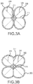
- beam structure 400 may be formed by bonding together two beams having an 1-cross section 300 ("I-cross section beams") or two beams having an H-cross section 302 ("H-cross section beams"), shown in Figures 3A and 3B , according to various embodiments.
- beam structure 400 may be formed by bonding together four beams, having circular cross sections 303, as shown in Figure 3C .
- beam structure 400 may be formed by bonding tube segments 304A and 304B on opposite sides of a tube having an H-cross section 302, or an I-cross section 300, as shown in Figure 3D .
- the sliding surface 102 may be bonded between the first rail beam 104 and the second rail beam 106.
- sliding surface 102 may be bonded at or around a peak point (i.e. first peak point 205a, second peak point 205b, third peak point 207a, or fourth peak point 207b, shown in Figure 2 ) of four-point cross section 200, as shown in Figure 1 .
- the sliding surface 102 may comprise a flexible fabric material such as a urethane rip stop material and/or a nylon based cloth with a urethane coating.
- the support structure 101 may further comprise a ground rail beam 109 bordering a bottom side of the sliding surface 102.
- ground rail beam 109 may have a four-point cross section, similar to the four-point cross section 200 of the first rail beam 104 and the second rail beam 106.
- ground rail beam 109 may have a circular or other cross section configuration, wherein the first rail beam 104 and the second rail beam 106 may each comprise the four-point cross section 200.
- the first rail beam 104 and the second rail beam 106 may be bonded to, or otherwise coupled with, the ground rail beam 109.
- the first rail beam 104, the second rail beam 106, and the ground rail beam 109 may form a continuous air filled unit (in response to inflation), in bordering engagement with sliding surface 102.
- the support structure 101 may further comprise other inflatable structural components, such as transverse support beams, drop down support(s), a slide ramp, etc., which traditionally have a circular cross section.
- any one of such other inflatable structural components may also comprise four-point cross section 200.
- any one of such other inflatable structural components may be bonded to, or otherwise coupled with, the first rail beam 104 and the second rail beam 106, or may form a continuous air filled unit therewith, according to various embodiments. Specific embodiments may take into account factors such as available material, required/ desired operational parameters, cost, slide design and size, etc.
- references to "various embodiments”, “one embodiment”, “an embodiment”, “an example embodiment”, etc. indicate that the embodiment described may include a particular feature, structure, or characteristic, but every embodiment may not necessarily include the particular feature, structure, or characteristic. Moreover, such phrases are not necessarily referring to the same embodiment. Further, when a particular feature, structure, or characteristic is described in connection with an embodiment, it is submitted that it is within the knowledge of one skilled in the art to affect such feature, structure, or characteristic in connection with other embodiments whether or not explicitly described. After reading the description, it will be apparent to one skilled in the relevant art(s) how to implement the disclosure in alternative embodiments.
Landscapes
- Engineering & Computer Science (AREA)
- Aviation & Aerospace Engineering (AREA)
- Business, Economics & Management (AREA)
- Emergency Management (AREA)
- Mechanical Engineering (AREA)
- Air Bags (AREA)
- Tents Or Canopies (AREA)
- Rod-Shaped Construction Members (AREA)
- Buildings Adapted To Withstand Abnormal External Influences (AREA)
Abstract
Description
- Typically, an inflatable aircraft evacuation slide comprising inflatable support beams requires sufficient strength in the beams to withstand high wind conditions and heavy loads imposed on the slide. Under current FAA standards, for example, under FAA Technical Standard Order C69c (TSO-C69c), a slide should have sufficient beam strength to withstand wind speeds as high as 25-30 knots (11.8-15.4 m/s), and to support sandbags weighing a total of 510 lbs (∼231kg) per slide lane. Therefore, inflatable support beams of typical evacuation slides require both vertical and horizontal strength in the support beams. Additionally, as the slide including an inflation source such as a compressed air cylinder, is typically packed within a small space in the aircraft, a reduction in the size of the slide and air cylinder, is desirable.
- In accordance with various embodiments, disclosed is an inflatable slide comprising:
- an elongated member comprising a sliding surface; and a support structure supporting the elongated member, the support structure comprising a first rail beam and a second rail beam bordering opposites sides of the elongated member, wherein the first rail beam and the second rail beam are inflatable, wherein the first rail beam and the second rail beam each have a four-point cross section, wherein the four-point cross section is defined by a longitudinal pair of opposite arcuate sections comprising a first arcuate section having a first peak point and a second arcuate section having a second peak point, and a transverse pair of opposite arcuate sections comprising a third arcuate section having a third peak point and a fourth arcuate section having a fourth peak point, wherein a longitudinal diameter between the first peak point and the second peak point intersects a transverse diameter between the third peak point and the fourth peak point, and wherein the four-point cross section is further defined by a first indent formed between the first arcuate section and the fourth arcuate section, a second indent formed between the second arcuate section and the third arcuate section, a third indent formed between the third arcuate section and the first arcuate section,
- and a fourth indent formed between the second arcuate section and the fourth arcuate section. In one embodiment, the inflatable slide is an aircraft emergency evacuation slide. In one embodiment, the longitudinal diameter equals the transverse diameter. In one embodiment, the longitudinal diameter and the transverse diameter intersect at about 90 degrees. In one embodiment, a first diameter between the first indent and the second indent intersects a second diameter between the third indent and the fourth indent at about 90 degrees. In one embodiment, the first diameter equals the second diameter. In one embodiment, the first diameter intersects the second diameter at about 90 degrees. In one embodiment, the four-point cross section is symmetrical about a central point, wherein the longitudinal diameter equals the transverse diameter, defining a large diameter of the four-point cross section, and the first diameter equals the second diameter, defining a small diameter of the four-point cross section, which is smaller than the large diameter. In one embodiment, a ratio between the small diameter to the large diameter is between 3:5 and 4:6. In one embodiment, the ratio between the small diameter to the large diameter is 4:5. In one embodiment, the sliding surface is bonded to the first rail beam at one of the first peak point, the second peak point, the third peak point, or the fourth peak point of the four-point cross section of the first rail beam, and wherein the sliding surface is bonded to the second rail beam at one of the first peak point, the second peak point, the third peak point, or the fourth peak point of the four-point cross section of the second rail beam.
- In accordance with various embodiments, disclosed is an inflatable support structure comprising: a flexible material formed into an inflatable elongated configuration having a cross section of which when inflated defines four arcuate sections each having a peak point defined by the largest radial extent of an outer surface of the inflatable support structure at each of the four arcuate sections, a first pair of opposing peak points defining a first large transverse dimension and a second pair of opposing peak points defining a second large transverse dimension, four indentations being defined perimetrically between the peak points each of the four indentations having an indent point defined by the smallest radial extent of the outer surface of the inflatable support structure between perimetrically adjacent peak points, a first pair of opposing indent points defining a first small transverse dimension and a second pair of opposing indent point defining a second small transverse dimension. In one embodiment, the flexible material, when inflated, forms at least one of a first rail beam and a second rail beam, the first rail beam and the second rail beam providing a support structure for an elongated member comprising a sliding surface of the support structure, wherein the first rail beam and the second rail beam border opposite sides of the elongated member comprising the sliding surface. In one embodiment, the flexible material, when inflated, further forms a ground rail beam bordering on a bottom side of the elongated member. In one embodiment, the four arcuate sections of the flexible material are formed from more than one continuous gas fill chamber. In one embodiment, the flexible material forms at least a portion of an inflatable slide.
- In accordance with various embodiments, disclosed is a support structure, the support structure comprising an inflatable four-point cross section beam structure, the four-point cross section beam structure including a four-point cross section, wherein the four-point cross section is defined by a longitudinal pair of opposite arcuate sections comprising a first arcuate section having a first peak point and a second arcuate section having a second peak point, and a transverse pair of opposite arcuate sections comprising a third arcuate section having a third peak point and a fourth arcuate section having a fourth peak point, wherein a first large transverse dimension between the first peak point and the second peak point intersects a second large transverse dimension between the third peak point and the fourth peak point, wherein the four-point cross section is further defined by a first indent formed between the first arcuate section and the fourth arcuate section, a second indent formed between the second arcuate section and the third arcuate section, a third indent formed between the third arcuate section and the first arcuate section, and a fourth indent formed between the second arcuate section and the fourth arcuate section, wherein a first small transverse dimension between the first indent and the second indent intersects a second small transverse dimension between the third indent and the fourth indent, and wherein the four-point cross section beam structure comprises at least one continuous gas fill chamber. In one embodiment, the four-point cross section is symmetrical about a central point, wherein the first large transverse dimension has a radial extent approximately equal to the radial extent of the second large transverse dimension, defining a large radial extent of the four-point cross section, and wherein the first large transverse dimension intersects the second large transverse dimension at about 90 degrees, wherein the first small transverse dimension has a radial extent approximately equal to the radial extent of the second small transverse dimension, defining a small radial extent of the four-point cross section, and wherein the first small transverse dimension and the second small transverse dimension intersect at about 90 degrees. In one embodiment, a ratio between the small radial extent to the large radial extent is between 3:5 and 4:6. In one embodiment, the inflatable article comprises an inflatable slide for emergency evacuation of an aircraft.
- The drawings described herein are for illustration purposes only and are not intended to limit the scope of the present disclosure in any way. The present disclosure will become more fully understood from the detailed description and the accompanying drawings wherein:
-
Figure 1A illustrates a segment of a beam structure having a four-point cross section, according to various embodiments; -
Figure 1B illustrates an inflatable slide including the beam structure ofFigure 1A , according to various embodiments; -
Figure 2 shows the four-point cross section of the beam structure ofFigure 1A , according to various embodiments; -
Figure 3A shows the four-point cross section ofFigure 2 , formed from two I-beam cross sections, according to various embodiments; -
Figure 3B shows the four-point cross section ofFigure 2 , formed from two H-beam cross sections, according to various embodiments; -
Figure 3C shows the four-point cross section ofFigure 2 , formed from four circular cross sections, according to various embodiments; and -
Figure 3D shows the four-point cross section ofFigure 2 , formed from an I-beam cross section and tube segments, and circular cross sections, according to various embodiments. - All ranges and ratio limits disclosed herein may be combined. It is to be understood that unless specifically stated otherwise, references to "a," "an," and/or "the" may include one or more than one and that reference to an item in the singular may also include the item in the plural.
- The detailed description of exemplary embodiments herein makes reference to the accompanying drawings, which show exemplary embodiments by way of illustration and its best mode, and not of limitation. While these exemplary embodiments are described in sufficient detail to enable those skilled in the art to practice the invention, it should be understood that other embodiments may be realized and that logical, chemical and mechanical changes may be made without departing from the spirit and scope of the invention. For example, the steps recited in any of the method or process descriptions may be executed in any order and are not necessarily limited to the order presented. Moreover, many of the functions or steps may be outsourced to or performed by one or more third parties. Furthermore, any reference to singular includes plural embodiments, and any reference to more than one component or step may include a singular embodiment or step. Also, any reference to attached, fixed, connected or the like may include permanent, removable, temporary, partial, full and/or any other possible attachment option. Additionally, any reference to without contact (or similar phrases) may also include reduced contact or minimal contact.
- In accordance with various embodiments, disclosed is a
beam structure 400, shown inFigure 1A , comprising a four-point cross section 200 (seeFigure 2 ) for an inflatable slide 100 (shown in an inflated state inFigure 1B ). In various embodiments, thebeam structure 400 comprises a flexible material formed into an inflatable elongated configuration having a cross section of which when inflated defines four arcuate sections ofbeam structure 400. The beam structure 400 (also referred to as "four-point crosssection beam structure 400") has greater beam strength and provides greater structural support than an inflatable beam having a traditional circular cross section. - In accordance with various embodiments, as shown in
Figure 1B , theinflatable slide 100 comprisingbeam structure 400, generally includes anelongated member 120 having a slidingsurface 102, supported by asupport structure 101 which comprises at least two rail beams comprising afirst rail beam 104 and asecond rail beam 106, which are inflatable, and have a four-point cross section 200, as shown inFigure 2 . According to various embodiments, thefirst rail beam 104 and thesecond rail beam 106 border opposite sides of theelongated member 120. - According to various embodiments, the
inflatable slide 100 comprisingbeam structure 400 may be used for emergency evacuation. According to various embodiments, theinflatable slide 100 is used for emergency evacuation of anaircraft 108 and is configured to pack within a compartment of the aircraft 108 (i.e. an aircraft door, a slide bustle, etc.). According to various embodiments, theinflatable slide 100 may be packed with an inflation source such as acompressed air cylinder 111. According to various embodiments, theinflatable slide 100 may be inflated at a pressure of between 2psi (13.8kPa) and 10psi (68.9kPA). - According to various embodiments, as shown in
Figure 2 , the four-point cross section 200 ofbeam structure 400, has a clover-like geometry, and may be defined by a longitudinal pair of opposite arcuate sections comprising a firstarcuate section 202a and a secondarcuate section 202b; and a transverse pair of opposite arcuate sections comprising a thirdarcuate section 204a and a fourtharcuate section 204b, wherein a first largetransverse dimension 206 defined between afirst peak point 205a of the firstarcuate section 202a and asecond peak point 205b of the secondarcuate section 202b, intersects with a second large transverse dimension 208) defined between athird peak point 207a of the thirdarcuate section 204a and afourth peak point 207b of the fourtharcuate section 204b. According to various embodiments, the first largetransverse dimension 206 equals the second large transverse dimension 208 (defining a large dimension of four-point cross section 200). According to various embodiments, the first largetransverse dimension 206 intersects the second largetransverse dimension 208 at about 90 degrees, wherein the term "about" in this context only means +/- 5 degrees. According to various embodiments, four-point cross section 200 may further be defined by afirst indent 212a formed between the firstarcuate section 202a and the fourtharcuate section 204b; asecond indent 212b formed between the secondarcuate section 202b and the thirdarcuate section 204a; athird indent 214a formed between the thirdarcuate section 204a and the firstarcuate section 202a; and afourth indent 214b formed between the secondarcuate section 202b and the fourtharcuate section 204b. A first smalltransverse dimension 210 defined between thefirst indent 212a and thesecond indent 212b intersects a second smalltransverse dimension 211 defined between thethird indent 214a and thefourth indent 214b. According to various embodiments, the first smalltransverse dimension 210 equals the second small transverse dimension 211 (defining a small diameter of four-point cross section 200). According to various embodiments, the first smalltransverse dimension 210 intersects the second small transverse dimension 211at about 90 degrees, wherein the term "about" in this context only means +/- 5 degrees. According to various embodiments, four-point cross section 200 is symmetrical about acentral point 201, wherein the first largetransverse dimension 206 equals the second largetransverse dimension 208, and wherein the first smalltransverse dimension 210 equals the secondsmall diameter 211. According to various embodiments, wherein four-point cross section 200 is symmetrical aboutcentral point 201, the ratio between the small diameter to the large diameter is between 3:5 and 4:6. According to various embodiments, the ratio of the small diameter to the large diameter is 4:5. - In comparison to a gas filled beam having a traditional circular cross section beam structure, a gas filled beam with the beam structure 400 (wherein the diameter of the circular cross section equals the large diameter of the four-point cross section 200) may have a 1%-5% increase in support strength and a reduced inflatable interior volume. According to various embodiments,
beam structure 400 including a small diameter of 16 inches (0.4064m) and a large diameter of 20 inches (0.508m) was found to have a 3.3% increase in support strength, and a 13% reduction of inflatable volume as compared to a circular cross section beam structure with a 20-inch (0.508m) diameter. The resultant volume reduction is advantageous for packing theinflatable slide 100, into a limited amount of space, as the sizes of both theinflatable slide 100 andcompressed air cylinder 111 are reduced. - According to various embodiments, the
beam structure 400 may comprise one continuous gas fillable chamber. According to various embodiments,beam structure 400 may comprise more than one air fill chambers. For example,beam structure 400 may be formed by bonding together two beams having an 1-cross section 300 ("I-cross section beams") or two beams having an H-cross section 302 ("H-cross section beams"), shown inFigures 3A and 3B , according to various embodiments. According to various embodiments,beam structure 400 may be formed by bonding together four beams, havingcircular cross sections 303, as shown inFigure 3C . According to various embodiments,beam structure 400 may be formed by bondingtube segments cross section 302, or an I-cross section 300, as shown inFigure 3D . - According to various embodiments, and with reference to
Figure 1B , the slidingsurface 102 may be bonded between thefirst rail beam 104 and thesecond rail beam 106. According to various embodiments, slidingsurface 102 may be bonded at or around a peak point (i.e.first peak point 205a,second peak point 205b,third peak point 207a, orfourth peak point 207b, shown inFigure 2 ) of four-point cross section 200, as shown inFigure 1 . According to various embodiments, the slidingsurface 102 may comprise a flexible fabric material such as a urethane rip stop material and/or a nylon based cloth with a urethane coating. - With continued reference to
FIG. 1 , according to various embodiments, thesupport structure 101 may further comprise aground rail beam 109 bordering a bottom side of the slidingsurface 102. According to various embodiments,ground rail beam 109 may have a four-point cross section, similar to the four-point cross section 200 of thefirst rail beam 104 and thesecond rail beam 106. According to various embodiments,ground rail beam 109 may have a circular or other cross section configuration, wherein thefirst rail beam 104 and thesecond rail beam 106 may each comprise the four-point cross section 200. According to various embodiments, thefirst rail beam 104 and thesecond rail beam 106 may be bonded to, or otherwise coupled with, theground rail beam 109. According to various embodiments, thefirst rail beam 104, thesecond rail beam 106, and theground rail beam 109 may form a continuous air filled unit (in response to inflation), in bordering engagement with slidingsurface 102. - According to various embodiments, the
support structure 101 may further comprise other inflatable structural components, such as transverse support beams, drop down support(s), a slide ramp, etc., which traditionally have a circular cross section. According to various embodiments, any one of such other inflatable structural components may also comprise four-point cross section 200. According to various embodiments, any one of such other inflatable structural components may be bonded to, or otherwise coupled with, thefirst rail beam 104 and thesecond rail beam 106, or may form a continuous air filled unit therewith, according to various embodiments. Specific embodiments may take into account factors such as available material, required/ desired operational parameters, cost, slide design and size, etc. - Systems and methods are provided. In the detailed description herein, references to "various embodiments", "one embodiment", "an embodiment", "an example embodiment", etc., indicate that the embodiment described may include a particular feature, structure, or characteristic, but every embodiment may not necessarily include the particular feature, structure, or characteristic. Moreover, such phrases are not necessarily referring to the same embodiment. Further, when a particular feature, structure, or characteristic is described in connection with an embodiment, it is submitted that it is within the knowledge of one skilled in the art to affect such feature, structure, or characteristic in connection with other embodiments whether or not explicitly described. After reading the description, it will be apparent to one skilled in the relevant art(s) how to implement the disclosure in alternative embodiments.
- Benefits, other advantages, and solutions to problems have been described herein with regard to specific embodiments. However, the benefits, advantages, solutions to problems, and any elements that may cause any benefit, advantage, or solution to occur or become more pronounced are not to be construed as critical, required, or essential features or elements of the invention. The scope of the invention is accordingly to be limited by nothing other than the appended claims, in which reference to an element in the singular is not intended to mean "one and only one" unless explicitly so stated, but rather "one or more." Moreover, where a phrase similar to "at least one of A, B, or C" is used in the claims, it is intended that the phrase be interpreted to mean that A alone may be present in an embodiment, B alone may be present in an embodiment, C alone may be present in an embodiment, or that any combination of the elements A, B and C may be present in a single embodiment; for example, A and B, A and C, B and C, or A and B and C. Furthermore, no element, component, or method step in the present disclosure is intended to be dedicated to the public regardless of whether the element, component, or method step is explicitly recited in the claims. No claim element herein is to be construed under the provisions of 35 U.S.C. 112(f) unless the element is expressly recited using the phrase "means for." As used herein, the terms "comprises", "comprising", or any other variation thereof, are intended to cover a non-exclusive inclusion, such that a process, method, article, or apparatus that comprises a list of elements does not include only those elements but may include other elements not expressly listed or inherent to such process, method, article, or apparatus.
Claims (15)
- An inflatable slide (100) comprising:an elongated member (120) comprising a sliding surface; anda support structure (101) supporting the elongated member (120), the support structure comprising a first rail beam and a second rail beam bordering opposites sides of the elongated member,wherein the first rail beam (104) and the second rail beam (106) are inflatable,wherein the first rail beam (104) and the second rail beam (106) each have a four-point cross section,wherein the four-point cross section is defined by a longitudinal pair of opposite arcuate sections comprising a first arcuate section (202a) having a first peak point and a second arcuate section (202b) having a second peak point, and a transverse pair of opposite arcuate sections comprising a third arcuate section (204a) having a third peak point and a fourth arcuate section (204b) having a fourth peak point,wherein a longitudinal diameter between the first peak point (205a) and the second peak point (205b) intersects a transverse diameter between the third peak point (207a) and the fourth peak point (207b), andwherein the four-point cross section is further defined by a first indent (212a) formed between the first arcuate section (202a) and the fourth arcuate section (204b), a second indent (212b) formed between the second arcuate section (202b) and the third arcuate section (204a), a third indent (214a) formed between the third arcuate (204a) section and the first arcuate section (202a), and a fourth indent (214b) formed between the second arcuate section (202b) and the fourth arcuate section (204b).
- The inflatable slide of claim 1, wherein the inflatable slide (100) is an aircraft emergency evacuation slide, and/or wherein the longitudinal diameter equals the transverse diameter, and/or wherein the longitudinal diameter and the transverse diameter intersect at about 90 degrees.
- The inflatable slide of claim 1 or 2, wherein a first diameter between the first indent (212a) and the second indent (212b) intersects a second diameter between the third indent (214a) and the fourth indent (214b) at about 90 degrees.
- The inflatable slide of claim 3, wherein the first diameter equals the second diameter, and/or wherein the first diameter intersects the second diameter at about 90 degrees.
- The inflatable slide of claim 3, wherein the four-point cross section is symmetrical about a central point, wherein the longitudinal diameter equals the transverse diameter, defining a large diameter of the four-point cross section, and the first diameter equals the second diameter, defining a small diameter of the four-point cross section, which is smaller than the large diameter.
- The inflatable slide of claim 5, wherein a ratio between the small diameter to the large diameter is between 3:5 and 4:6, and/or wherein the ratio between the small diameter to the large diameter is 4:5.
- The inflatable slide of any preceding claim, wherein
the sliding surface is bonded to the first rail beam (104) at one of the first peak point, the second peak point, the third peak point, or the fourth peak point of the four-point cross section of the first rail beam (104), and
wherein the sliding surface is bonded to the second rail beam (106) at one of the first peak point, the second peak point, the third peak point, or the fourth peak point of the four-point cross section of the second rail beam (106). - An inflatable support structure comprising:a flexible material formed into an inflatable elongated configuration having a cross section of which when inflated defines four arcuate sections each having a peak point defined by the largest radial extent of an outer surface of the inflatable support structure at each of the four arcuate sections, a first pair of opposing peak points defining a first large transverse dimension and a second pair of opposing peak points defining a second large transverse dimension, four indentations (212a, 212b, 214a, 214b) being defined perimetrically between the peak points each of the four indentations having an indent point defined by the smallest radial extent of the outer surface of the inflatable support structure between perimetrically adjacent peak points, a first pair of opposing indent points defining a first small transverse dimension and a second pair of opposing indent point defining a second small transverse dimension.
- The inflatable support structure of claim 8, wherein the flexible material, when inflated, forms at least one of a first rail beam (104) and a second rail beam (106), the first rail beam (104) and the second rail beam (106) providing a support structure for an elongated member (120) comprising a sliding surface of the support structure (101), wherein the first rail beam (104) and the second rail beam (106) border opposite sides of the elongated member (120) comprising the sliding surface.
- The inflatable support structure of claim 9, wherein the flexible material, when inflated, further forms a ground rail beam bordering on a bottom side of the elongated member.
- The inflatable support structure of claim 8, 9 or 10 wherein the four arcuate sections (202a, 202b, 204a, 202b) of the flexible material are formed from more than one continuous gas fill chamber.
- The inflatable support structure of claim 11 wherein the flexible material forms at least a portion of an inflatable slide (100).
- An inflatable article comprising a support structure, the support structure comprising an inflatable four-point cross section beam structure, the four-point cross section beam structure including a four-point cross section,
wherein the four-point cross section is defined by a longitudinal pair of opposite arcuate sections comprising a first arcuate section (202a) having a first peak point and a second arcuate section (202b) having a second peak point, and a transverse pair of opposite arcuate sections comprising a third arcuate section (204a) having a third peak point and a fourth arcuate section (204b) having a fourth peak point,
wherein a first large transverse dimension between the first peak point and the second peak point intersects a second large transverse dimension between the third peak point and the fourth peak point,
wherein the four-point cross section is further defined by a first indent (212a) formed between the first arcuate section (202a) and the fourth arcuate section (204b), a second indent (212b) formed between the second arcuate section (202b) and the third arcuate section (204a), a third indent (214b) formed between the third arcuate section (204a) and the first arcuate section (202a), and a fourth indent (214b) formed between the second arcuate section (202b) and the fourth arcuate section (204b), wherein a first small transverse dimension between the first indent (212a) and the second indent (212b) intersects a second small transverse dimension between the third indent (214a) and the fourth indent (214b), and
wherein the four-point cross section beam structure comprises at least one continuous gas fill chamber. - The inflatable article of claim 13, wherein the four-point cross section is symmetrical about a central point, wherein the first large transverse dimension has a radial extent approximately equal to the radial extent of the second large transverse dimension,
defining a large radial extent of the four-point cross section, and wherein the first large transverse dimension intersects the second large transverse dimension at about 90 degrees,
wherein the first small transverse dimension has a radial extent approximately equal to the radial extent of the second small transverse dimension, defining a small radial extent of the four-point cross section, and
wherein the first small transverse dimension and the second small transverse dimension intersect at about 90 degrees, and preferably wherein a ratio between the small radial extent to the large radial extent is between 3:5 and 4:6. - The inflatable article of claim 13 or 14, comprising an inflatable slide (100) for emergency evacuation of an aircraft.
Applications Claiming Priority (1)
| Application Number | Priority Date | Filing Date | Title |
|---|---|---|---|
| US14/886,499 US10118708B2 (en) | 2015-10-19 | 2015-10-19 | Evacuation slide with beam structure comprising four-point cross section |
Publications (2)
| Publication Number | Publication Date |
|---|---|
| EP3159267A1 true EP3159267A1 (en) | 2017-04-26 |
| EP3159267B1 EP3159267B1 (en) | 2019-05-15 |
Family
ID=57178282
Family Applications (1)
| Application Number | Title | Priority Date | Filing Date |
|---|---|---|---|
| EP16194317.0A Active EP3159267B1 (en) | 2015-10-19 | 2016-10-18 | Evacuation slide with beam structure comprising four-point cross section |
Country Status (4)
| Country | Link |
|---|---|
| US (1) | US10118708B2 (en) |
| EP (1) | EP3159267B1 (en) |
| CN (1) | CN106985999B (en) |
| BR (1) | BR102016019202B1 (en) |
Families Citing this family (3)
| Publication number | Priority date | Publication date | Assignee | Title |
|---|---|---|---|---|
| US11345478B2 (en) * | 2019-09-26 | 2022-05-31 | Goodrich Corporation | Evacuation slide and method of forming evacuation slide having integral cable channel |
| PL432278A1 (en) * | 2019-12-18 | 2021-06-28 | Instytut Formy Spółka Z Ograniczoną Odpowiedzialnością | Multi-chamber construction element and method of producing thereof |
| CN111959797B (en) * | 2020-08-25 | 2021-11-19 | 南京禹智智能科技有限公司 | Escape and rescue equipment special for large-scale aviation airliner |
Citations (3)
| Publication number | Priority date | Publication date | Assignee | Title |
|---|---|---|---|---|
| GB1246999A (en) * | 1968-02-01 | 1971-09-22 | Switlik Parachute Co Inc | Inflatable evacuation slide |
| US3860984A (en) * | 1973-06-25 | 1975-01-21 | Goodrich Co B F | Inflatable life raft escape slide |
| GB1403504A (en) * | 1973-09-04 | 1975-08-20 | Goodrich Co B F | Inflatable escape slide |
Family Cites Families (16)
| Publication number | Priority date | Publication date | Assignee | Title |
|---|---|---|---|---|
| US3370684A (en) * | 1966-09-08 | 1968-02-27 | Ind Covers Inc | Inflatable escape slide |
| FR96018E (en) * | 1967-10-23 | 1972-05-19 | Goodrich Co B F | Pneumatic rescue slide. |
| US3712417A (en) * | 1971-04-05 | 1973-01-23 | Sargent Industries | Inflatable evacuation slide |
| US4519782A (en) * | 1980-02-19 | 1985-05-28 | The B. F. Goodrich Company | Escape slide and life raft |
| US4434870A (en) * | 1982-11-22 | 1984-03-06 | The B. F. Goodrich Company | Evacuation slide device |
| US4846422A (en) * | 1984-05-14 | 1989-07-11 | The Bfgoodrich Company | Single piece evacuation system for aircraft or the like |
| US5311706A (en) | 1991-07-19 | 1994-05-17 | Tracor Aerospace, Inc. | Inflatable truss frame |
| CN1087702C (en) * | 1996-08-22 | 2002-07-17 | 波音公司 | Mechanism for arming, disarming and activating airplane emergency slide evacuation systems |
| US6471001B1 (en) * | 1999-10-06 | 2002-10-29 | The B.F. Goodrich Corporation | Escape slide |
| US6463699B1 (en) | 2001-03-23 | 2002-10-15 | Obi Corporation | Air beam construction using differential pressure chambers |
| US6454220B1 (en) * | 2001-10-11 | 2002-09-24 | Goodrich Coporation | Evacuation slide with toe end center support member |
| US6695096B2 (en) * | 2001-10-16 | 2004-02-24 | Goodrich Corporation | Evacuation slide having toe end transverse support tube |
| US6966414B2 (en) * | 2003-12-02 | 2005-11-22 | Goodrich Corporation | Elevated inflatable emergency evacuation slide illumination |
| US8215586B2 (en) * | 2009-04-08 | 2012-07-10 | Air Cruisers Company | Evacuation slide systems |
| FR2946615B1 (en) | 2009-06-12 | 2011-05-27 | Zodiac Solas | INFLATABLE EXHAUST RAMP, AND RESCUE INSTALLATION FOR SHIP, COMPRISING SAME. |
| US8663762B2 (en) * | 2011-06-08 | 2014-03-04 | Goodrich Corporation | High-strength lightweight fabric for inflatable structures |
-
2015
- 2015-10-19 US US14/886,499 patent/US10118708B2/en active Active
-
2016
- 2016-08-19 BR BR102016019202-1A patent/BR102016019202B1/en active IP Right Grant
- 2016-10-18 EP EP16194317.0A patent/EP3159267B1/en active Active
- 2016-10-19 CN CN201610908697.1A patent/CN106985999B/en active Active
Patent Citations (3)
| Publication number | Priority date | Publication date | Assignee | Title |
|---|---|---|---|---|
| GB1246999A (en) * | 1968-02-01 | 1971-09-22 | Switlik Parachute Co Inc | Inflatable evacuation slide |
| US3860984A (en) * | 1973-06-25 | 1975-01-21 | Goodrich Co B F | Inflatable life raft escape slide |
| GB1403504A (en) * | 1973-09-04 | 1975-08-20 | Goodrich Co B F | Inflatable escape slide |
Also Published As
| Publication number | Publication date |
|---|---|
| EP3159267B1 (en) | 2019-05-15 |
| BR102016019202A2 (en) | 2017-05-02 |
| US20170106988A1 (en) | 2017-04-20 |
| BR102016019202B1 (en) | 2022-12-06 |
| US10118708B2 (en) | 2018-11-06 |
| CN106985999A (en) | 2017-07-28 |
| CN106985999B (en) | 2021-05-11 |
Similar Documents
| Publication | Publication Date | Title |
|---|---|---|
| EP3159267B1 (en) | Evacuation slide with beam structure comprising four-point cross section | |
| KR102089394B1 (en) | Self-reinflating tire | |
| AU2017350476B2 (en) | Evacuation system | |
| US20150335164A1 (en) | Internal supports for inflatable products | |
| CN106347680B (en) | Retractable/extendable suction system | |
| CN116335739B (en) | A multi-stage pressure relief and anti-collision device suitable for anchor support | |
| CN203902467U (en) | Car roof collapse-resistant device and automobile | |
| US20150108277A1 (en) | Device and method for rescuing from a high-rise facility | |
| WO2018132332A8 (en) | Occupant protection system including expandable curtain and/or expandable bladder | |
| EP2551629A3 (en) | Inflator device with fuel-rich monolithic grain and oxidant-enhanced combustion | |
| EP3124383B1 (en) | Telescoping evacuation slide | |
| JPH10297598A (en) | Emergency slide equipped with hanger tubular assembly | |
| AU2015365265B2 (en) | Thin air jack | |
| EP2181035B1 (en) | Triangular inflatable evacuation slide | |
| US10000291B2 (en) | Aircraft evacuation slide | |
| US20250318659A1 (en) | Universal air surface | |
| DE60103733T2 (en) | SUPPORT STRIPS FOR AN EMERGENCY TIRE | |
| EP2994352B1 (en) | Airbag for a motor vehicle | |
| EP3786367A3 (en) | Stabilization methods and system | |
| CN111042622A (en) | Inflatable easy-to-break rod | |
| CN212583400U (en) | An inflatable easy-to-fold rod | |
| CN103264278B (en) | Wheel set production line | |
| CN110344864B (en) | Anchor rod and its use method | |
| US20210354834A1 (en) | Integrated Truss Restraint | |
| CN107042874A (en) | Floating gasbag |
Legal Events
| Date | Code | Title | Description |
|---|---|---|---|
| PUAI | Public reference made under article 153(3) epc to a published international application that has entered the european phase |
Free format text: ORIGINAL CODE: 0009012 |
|
| STAA | Information on the status of an ep patent application or granted ep patent |
Free format text: STATUS: THE APPLICATION HAS BEEN PUBLISHED |
|
| AK | Designated contracting states |
Kind code of ref document: A1 Designated state(s): AL AT BE BG CH CY CZ DE DK EE ES FI FR GB GR HR HU IE IS IT LI LT LU LV MC MK MT NL NO PL PT RO RS SE SI SK SM TR |
|
| AX | Request for extension of the european patent |
Extension state: BA ME |
|
| RIN1 | Information on inventor provided before grant (corrected) |
Inventor name: HARTMAN, DREW Inventor name: VOLNY, JARO S. |
|
| STAA | Information on the status of an ep patent application or granted ep patent |
Free format text: STATUS: REQUEST FOR EXAMINATION WAS MADE |
|
| 17P | Request for examination filed |
Effective date: 20171026 |
|
| RBV | Designated contracting states (corrected) |
Designated state(s): AL AT BE BG CH CY CZ DE DK EE ES FI FR GB GR HR HU IE IS IT LI LT LU LV MC MK MT NL NO PL PT RO RS SE SI SK SM TR |
|
| STAA | Information on the status of an ep patent application or granted ep patent |
Free format text: STATUS: EXAMINATION IS IN PROGRESS |
|
| 17Q | First examination report despatched |
Effective date: 20171214 |
|
| GRAP | Despatch of communication of intention to grant a patent |
Free format text: ORIGINAL CODE: EPIDOSNIGR1 |
|
| STAA | Information on the status of an ep patent application or granted ep patent |
Free format text: STATUS: GRANT OF PATENT IS INTENDED |
|
| INTG | Intention to grant announced |
Effective date: 20180718 |
|
| GRAJ | Information related to disapproval of communication of intention to grant by the applicant or resumption of examination proceedings by the epo deleted |
Free format text: ORIGINAL CODE: EPIDOSDIGR1 |
|
| STAA | Information on the status of an ep patent application or granted ep patent |
Free format text: STATUS: EXAMINATION IS IN PROGRESS |
|
| GRAP | Despatch of communication of intention to grant a patent |
Free format text: ORIGINAL CODE: EPIDOSNIGR1 |
|
| STAA | Information on the status of an ep patent application or granted ep patent |
Free format text: STATUS: GRANT OF PATENT IS INTENDED |
|
| INTC | Intention to grant announced (deleted) | ||
| INTG | Intention to grant announced |
Effective date: 20181129 |
|
| GRAS | Grant fee paid |
Free format text: ORIGINAL CODE: EPIDOSNIGR3 |
|
| GRAA | (expected) grant |
Free format text: ORIGINAL CODE: 0009210 |
|
| STAA | Information on the status of an ep patent application or granted ep patent |
Free format text: STATUS: THE PATENT HAS BEEN GRANTED |
|
| AK | Designated contracting states |
Kind code of ref document: B1 Designated state(s): AL AT BE BG CH CY CZ DE DK EE ES FI FR GB GR HR HU IE IS IT LI LT LU LV MC MK MT NL NO PL PT RO RS SE SI SK SM TR |
|
| REG | Reference to a national code |
Ref country code: CH Ref legal event code: EP |
|
| REG | Reference to a national code |
Ref country code: IE Ref legal event code: FG4D |
|
| REG | Reference to a national code |
Ref country code: DE Ref legal event code: R096 Ref document number: 602016013946 Country of ref document: DE |
|
| REG | Reference to a national code |
Ref country code: NL Ref legal event code: MP Effective date: 20190515 |
|
| REG | Reference to a national code |
Ref country code: LT Ref legal event code: MG4D |
|
| PG25 | Lapsed in a contracting state [announced via postgrant information from national office to epo] |
Ref country code: FI Free format text: LAPSE BECAUSE OF FAILURE TO SUBMIT A TRANSLATION OF THE DESCRIPTION OR TO PAY THE FEE WITHIN THE PRESCRIBED TIME-LIMIT Effective date: 20190515 Ref country code: NO Free format text: LAPSE BECAUSE OF FAILURE TO SUBMIT A TRANSLATION OF THE DESCRIPTION OR TO PAY THE FEE WITHIN THE PRESCRIBED TIME-LIMIT Effective date: 20190815 Ref country code: ES Free format text: LAPSE BECAUSE OF FAILURE TO SUBMIT A TRANSLATION OF THE DESCRIPTION OR TO PAY THE FEE WITHIN THE PRESCRIBED TIME-LIMIT Effective date: 20190515 Ref country code: AL Free format text: LAPSE BECAUSE OF FAILURE TO SUBMIT A TRANSLATION OF THE DESCRIPTION OR TO PAY THE FEE WITHIN THE PRESCRIBED TIME-LIMIT Effective date: 20190515 Ref country code: PT Free format text: LAPSE BECAUSE OF FAILURE TO SUBMIT A TRANSLATION OF THE DESCRIPTION OR TO PAY THE FEE WITHIN THE PRESCRIBED TIME-LIMIT Effective date: 20190915 Ref country code: HR Free format text: LAPSE BECAUSE OF FAILURE TO SUBMIT A TRANSLATION OF THE DESCRIPTION OR TO PAY THE FEE WITHIN THE PRESCRIBED TIME-LIMIT Effective date: 20190515 Ref country code: NL Free format text: LAPSE BECAUSE OF FAILURE TO SUBMIT A TRANSLATION OF THE DESCRIPTION OR TO PAY THE FEE WITHIN THE PRESCRIBED TIME-LIMIT Effective date: 20190515 Ref country code: SE Free format text: LAPSE BECAUSE OF FAILURE TO SUBMIT A TRANSLATION OF THE DESCRIPTION OR TO PAY THE FEE WITHIN THE PRESCRIBED TIME-LIMIT Effective date: 20190515 Ref country code: LT Free format text: LAPSE BECAUSE OF FAILURE TO SUBMIT A TRANSLATION OF THE DESCRIPTION OR TO PAY THE FEE WITHIN THE PRESCRIBED TIME-LIMIT Effective date: 20190515 |
|
| PG25 | Lapsed in a contracting state [announced via postgrant information from national office to epo] |
Ref country code: LV Free format text: LAPSE BECAUSE OF FAILURE TO SUBMIT A TRANSLATION OF THE DESCRIPTION OR TO PAY THE FEE WITHIN THE PRESCRIBED TIME-LIMIT Effective date: 20190515 Ref country code: RS Free format text: LAPSE BECAUSE OF FAILURE TO SUBMIT A TRANSLATION OF THE DESCRIPTION OR TO PAY THE FEE WITHIN THE PRESCRIBED TIME-LIMIT Effective date: 20190515 Ref country code: BG Free format text: LAPSE BECAUSE OF FAILURE TO SUBMIT A TRANSLATION OF THE DESCRIPTION OR TO PAY THE FEE WITHIN THE PRESCRIBED TIME-LIMIT Effective date: 20190815 Ref country code: GR Free format text: LAPSE BECAUSE OF FAILURE TO SUBMIT A TRANSLATION OF THE DESCRIPTION OR TO PAY THE FEE WITHIN THE PRESCRIBED TIME-LIMIT Effective date: 20190816 |
|
| REG | Reference to a national code |
Ref country code: AT Ref legal event code: MK05 Ref document number: 1133144 Country of ref document: AT Kind code of ref document: T Effective date: 20190515 |
|
| PG25 | Lapsed in a contracting state [announced via postgrant information from national office to epo] |
Ref country code: SK Free format text: LAPSE BECAUSE OF FAILURE TO SUBMIT A TRANSLATION OF THE DESCRIPTION OR TO PAY THE FEE WITHIN THE PRESCRIBED TIME-LIMIT Effective date: 20190515 Ref country code: EE Free format text: LAPSE BECAUSE OF FAILURE TO SUBMIT A TRANSLATION OF THE DESCRIPTION OR TO PAY THE FEE WITHIN THE PRESCRIBED TIME-LIMIT Effective date: 20190515 Ref country code: AT Free format text: LAPSE BECAUSE OF FAILURE TO SUBMIT A TRANSLATION OF THE DESCRIPTION OR TO PAY THE FEE WITHIN THE PRESCRIBED TIME-LIMIT Effective date: 20190515 Ref country code: DK Free format text: LAPSE BECAUSE OF FAILURE TO SUBMIT A TRANSLATION OF THE DESCRIPTION OR TO PAY THE FEE WITHIN THE PRESCRIBED TIME-LIMIT Effective date: 20190515 Ref country code: CZ Free format text: LAPSE BECAUSE OF FAILURE TO SUBMIT A TRANSLATION OF THE DESCRIPTION OR TO PAY THE FEE WITHIN THE PRESCRIBED TIME-LIMIT Effective date: 20190515 |
|
| REG | Reference to a national code |
Ref country code: DE Ref legal event code: R097 Ref document number: 602016013946 Country of ref document: DE |
|
| PG25 | Lapsed in a contracting state [announced via postgrant information from national office to epo] |
Ref country code: IT Free format text: LAPSE BECAUSE OF FAILURE TO SUBMIT A TRANSLATION OF THE DESCRIPTION OR TO PAY THE FEE WITHIN THE PRESCRIBED TIME-LIMIT Effective date: 20190515 Ref country code: SM Free format text: LAPSE BECAUSE OF FAILURE TO SUBMIT A TRANSLATION OF THE DESCRIPTION OR TO PAY THE FEE WITHIN THE PRESCRIBED TIME-LIMIT Effective date: 20190515 |
|
| PLBE | No opposition filed within time limit |
Free format text: ORIGINAL CODE: 0009261 |
|
| STAA | Information on the status of an ep patent application or granted ep patent |
Free format text: STATUS: NO OPPOSITION FILED WITHIN TIME LIMIT |
|
| PG25 | Lapsed in a contracting state [announced via postgrant information from national office to epo] |
Ref country code: TR Free format text: LAPSE BECAUSE OF FAILURE TO SUBMIT A TRANSLATION OF THE DESCRIPTION OR TO PAY THE FEE WITHIN THE PRESCRIBED TIME-LIMIT Effective date: 20190515 |
|
| 26N | No opposition filed |
Effective date: 20200218 |
|
| PG25 | Lapsed in a contracting state [announced via postgrant information from national office to epo] |
Ref country code: PL Free format text: LAPSE BECAUSE OF FAILURE TO SUBMIT A TRANSLATION OF THE DESCRIPTION OR TO PAY THE FEE WITHIN THE PRESCRIBED TIME-LIMIT Effective date: 20190515 |
|
| PG25 | Lapsed in a contracting state [announced via postgrant information from national office to epo] |
Ref country code: SI Free format text: LAPSE BECAUSE OF FAILURE TO SUBMIT A TRANSLATION OF THE DESCRIPTION OR TO PAY THE FEE WITHIN THE PRESCRIBED TIME-LIMIT Effective date: 20190515 Ref country code: MC Free format text: LAPSE BECAUSE OF FAILURE TO SUBMIT A TRANSLATION OF THE DESCRIPTION OR TO PAY THE FEE WITHIN THE PRESCRIBED TIME-LIMIT Effective date: 20190515 |
|
| REG | Reference to a national code |
Ref country code: CH Ref legal event code: PL |
|
| PG25 | Lapsed in a contracting state [announced via postgrant information from national office to epo] |
Ref country code: LI Free format text: LAPSE BECAUSE OF NON-PAYMENT OF DUE FEES Effective date: 20191031 Ref country code: CH Free format text: LAPSE BECAUSE OF NON-PAYMENT OF DUE FEES Effective date: 20191031 Ref country code: LU Free format text: LAPSE BECAUSE OF NON-PAYMENT OF DUE FEES Effective date: 20191018 |
|
| REG | Reference to a national code |
Ref country code: BE Ref legal event code: MM Effective date: 20191031 |
|
| PG25 | Lapsed in a contracting state [announced via postgrant information from national office to epo] |
Ref country code: BE Free format text: LAPSE BECAUSE OF NON-PAYMENT OF DUE FEES Effective date: 20191031 |
|
| PG25 | Lapsed in a contracting state [announced via postgrant information from national office to epo] |
Ref country code: IE Free format text: LAPSE BECAUSE OF NON-PAYMENT OF DUE FEES Effective date: 20191018 |
|
| PG25 | Lapsed in a contracting state [announced via postgrant information from national office to epo] |
Ref country code: RO Free format text: LAPSE BECAUSE OF FAILURE TO SUBMIT A TRANSLATION OF THE DESCRIPTION OR TO PAY THE FEE WITHIN THE PRESCRIBED TIME-LIMIT Effective date: 20190515 |
|
| PG25 | Lapsed in a contracting state [announced via postgrant information from national office to epo] |
Ref country code: CY Free format text: LAPSE BECAUSE OF FAILURE TO SUBMIT A TRANSLATION OF THE DESCRIPTION OR TO PAY THE FEE WITHIN THE PRESCRIBED TIME-LIMIT Effective date: 20190515 |
|
| GBPC | Gb: european patent ceased through non-payment of renewal fee |
Effective date: 20201018 |
|
| PG25 | Lapsed in a contracting state [announced via postgrant information from national office to epo] |
Ref country code: IS Free format text: LAPSE BECAUSE OF FAILURE TO SUBMIT A TRANSLATION OF THE DESCRIPTION OR TO PAY THE FEE WITHIN THE PRESCRIBED TIME-LIMIT Effective date: 20190915 |
|
| PG25 | Lapsed in a contracting state [announced via postgrant information from national office to epo] |
Ref country code: MT Free format text: LAPSE BECAUSE OF FAILURE TO SUBMIT A TRANSLATION OF THE DESCRIPTION OR TO PAY THE FEE WITHIN THE PRESCRIBED TIME-LIMIT Effective date: 20190515 Ref country code: HU Free format text: LAPSE BECAUSE OF FAILURE TO SUBMIT A TRANSLATION OF THE DESCRIPTION OR TO PAY THE FEE WITHIN THE PRESCRIBED TIME-LIMIT; INVALID AB INITIO Effective date: 20161018 |
|
| PG25 | Lapsed in a contracting state [announced via postgrant information from national office to epo] |
Ref country code: GB Free format text: LAPSE BECAUSE OF NON-PAYMENT OF DUE FEES Effective date: 20201018 |
|
| PG25 | Lapsed in a contracting state [announced via postgrant information from national office to epo] |
Ref country code: MK Free format text: LAPSE BECAUSE OF FAILURE TO SUBMIT A TRANSLATION OF THE DESCRIPTION OR TO PAY THE FEE WITHIN THE PRESCRIBED TIME-LIMIT Effective date: 20190515 |
|
| P01 | Opt-out of the competence of the unified patent court (upc) registered |
Effective date: 20230522 |
|
| PGFP | Annual fee paid to national office [announced via postgrant information from national office to epo] |
Ref country code: FR Payment date: 20250924 Year of fee payment: 10 |
|
| PGFP | Annual fee paid to national office [announced via postgrant information from national office to epo] |
Ref country code: DE Payment date: 20250923 Year of fee payment: 10 |