EP3159201A1 - Integrierte einlass- und entlüftungsanordnung für ein nutzfahrzeug - Google Patents
Integrierte einlass- und entlüftungsanordnung für ein nutzfahrzeug Download PDFInfo
- Publication number
- EP3159201A1 EP3159201A1 EP16195126.4A EP16195126A EP3159201A1 EP 3159201 A1 EP3159201 A1 EP 3159201A1 EP 16195126 A EP16195126 A EP 16195126A EP 3159201 A1 EP3159201 A1 EP 3159201A1
- Authority
- EP
- European Patent Office
- Prior art keywords
- compartment
- component
- deaeration
- intake
- engine
- Prior art date
- Legal status (The legal status is an assumption and is not a legal conclusion. Google has not performed a legal analysis and makes no representation as to the accuracy of the status listed.)
- Granted
Links
- 239000002826 coolant Substances 0.000 claims abstract description 84
- 239000012530 fluid Substances 0.000 claims abstract description 83
- 238000004519 manufacturing process Methods 0.000 claims description 17
- 238000001816 cooling Methods 0.000 claims description 14
- 238000000034 method Methods 0.000 claims description 9
- 238000012546 transfer Methods 0.000 claims description 8
- 230000008878 coupling Effects 0.000 claims description 6
- 238000010168 coupling process Methods 0.000 claims description 6
- 238000005859 coupling reaction Methods 0.000 claims description 6
- 238000002347 injection Methods 0.000 claims description 6
- 239000007924 injection Substances 0.000 claims description 6
- 239000000463 material Substances 0.000 claims description 6
- 239000004677 Nylon Substances 0.000 claims description 4
- 239000004743 Polypropylene Substances 0.000 claims description 4
- 229920001778 nylon Polymers 0.000 claims description 4
- -1 polypropylene Polymers 0.000 claims description 4
- 229920001155 polypropylene Polymers 0.000 claims description 4
- 238000003466 welding Methods 0.000 claims description 3
- 238000011144 upstream manufacturing Methods 0.000 claims description 2
- 239000011347 resin Substances 0.000 claims 4
- 229920005989 resin Polymers 0.000 claims 4
- 239000000853 adhesive Substances 0.000 claims 1
- 230000001070 adhesive effect Effects 0.000 claims 1
- 238000010586 diagram Methods 0.000 description 4
- LYCAIKOWRPUZTN-UHFFFAOYSA-N Ethylene glycol Chemical compound OCCO LYCAIKOWRPUZTN-UHFFFAOYSA-N 0.000 description 3
- OKKJLVBELUTLKV-UHFFFAOYSA-N Methanol Chemical compound OC OKKJLVBELUTLKV-UHFFFAOYSA-N 0.000 description 3
- DNIAPMSPPWPWGF-UHFFFAOYSA-N Propylene glycol Chemical compound CC(O)CO DNIAPMSPPWPWGF-UHFFFAOYSA-N 0.000 description 3
- 238000002485 combustion reaction Methods 0.000 description 3
- 230000008901 benefit Effects 0.000 description 2
- 230000005540 biological transmission Effects 0.000 description 2
- 238000013461 design Methods 0.000 description 2
- 238000011161 development Methods 0.000 description 2
- 230000002708 enhancing effect Effects 0.000 description 2
- 238000001746 injection moulding Methods 0.000 description 2
- 239000000203 mixture Substances 0.000 description 2
- 238000012986 modification Methods 0.000 description 2
- 230000004048 modification Effects 0.000 description 2
- XLYOFNOQVPJJNP-UHFFFAOYSA-N water Substances O XLYOFNOQVPJJNP-UHFFFAOYSA-N 0.000 description 2
- LFQSCWFLJHTTHZ-UHFFFAOYSA-N Ethanol Chemical compound CCO LFQSCWFLJHTTHZ-UHFFFAOYSA-N 0.000 description 1
- 238000010276 construction Methods 0.000 description 1
- 230000001186 cumulative effect Effects 0.000 description 1
- 230000003247 decreasing effect Effects 0.000 description 1
- 230000008030 elimination Effects 0.000 description 1
- 238000003379 elimination reaction Methods 0.000 description 1
- 230000007613 environmental effect Effects 0.000 description 1
- 239000000446 fuel Substances 0.000 description 1
- 239000007788 liquid Substances 0.000 description 1
- 239000000155 melt Substances 0.000 description 1
- 238000004806 packaging method and process Methods 0.000 description 1
- 230000008569 process Effects 0.000 description 1
Images

Classifications
-
- F—MECHANICAL ENGINEERING; LIGHTING; HEATING; WEAPONS; BLASTING
- F01—MACHINES OR ENGINES IN GENERAL; ENGINE PLANTS IN GENERAL; STEAM ENGINES
- F01P—COOLING OF MACHINES OR ENGINES IN GENERAL; COOLING OF INTERNAL-COMBUSTION ENGINES
- F01P11/00—Component parts, details, or accessories not provided for in, or of interest apart from, groups F01P1/00 - F01P9/00
- F01P11/02—Liquid-coolant filling, overflow, venting, or draining devices
- F01P11/028—Deaeration devices
-
- B—PERFORMING OPERATIONS; TRANSPORTING
- B60—VEHICLES IN GENERAL
- B60K—ARRANGEMENT OR MOUNTING OF PROPULSION UNITS OR OF TRANSMISSIONS IN VEHICLES; ARRANGEMENT OR MOUNTING OF PLURAL DIVERSE PRIME-MOVERS IN VEHICLES; AUXILIARY DRIVES FOR VEHICLES; INSTRUMENTATION OR DASHBOARDS FOR VEHICLES; ARRANGEMENTS IN CONNECTION WITH COOLING, AIR INTAKE, GAS EXHAUST OR FUEL SUPPLY OF PROPULSION UNITS IN VEHICLES
- B60K11/00—Arrangement in connection with cooling of propulsion units
- B60K11/02—Arrangement in connection with cooling of propulsion units with liquid cooling
- B60K11/04—Arrangement or mounting of radiators, radiator shutters, or radiator blinds
-
- B—PERFORMING OPERATIONS; TRANSPORTING
- B60—VEHICLES IN GENERAL
- B60K—ARRANGEMENT OR MOUNTING OF PROPULSION UNITS OR OF TRANSMISSIONS IN VEHICLES; ARRANGEMENT OR MOUNTING OF PLURAL DIVERSE PRIME-MOVERS IN VEHICLES; AUXILIARY DRIVES FOR VEHICLES; INSTRUMENTATION OR DASHBOARDS FOR VEHICLES; ARRANGEMENTS IN CONNECTION WITH COOLING, AIR INTAKE, GAS EXHAUST OR FUEL SUPPLY OF PROPULSION UNITS IN VEHICLES
- B60K11/00—Arrangement in connection with cooling of propulsion units
- B60K11/06—Arrangement in connection with cooling of propulsion units with air cooling
-
- B—PERFORMING OPERATIONS; TRANSPORTING
- B60—VEHICLES IN GENERAL
- B60K—ARRANGEMENT OR MOUNTING OF PROPULSION UNITS OR OF TRANSMISSIONS IN VEHICLES; ARRANGEMENT OR MOUNTING OF PLURAL DIVERSE PRIME-MOVERS IN VEHICLES; AUXILIARY DRIVES FOR VEHICLES; INSTRUMENTATION OR DASHBOARDS FOR VEHICLES; ARRANGEMENTS IN CONNECTION WITH COOLING, AIR INTAKE, GAS EXHAUST OR FUEL SUPPLY OF PROPULSION UNITS IN VEHICLES
- B60K11/00—Arrangement in connection with cooling of propulsion units
- B60K11/08—Air inlets for cooling; Shutters or blinds therefor
-
- B—PERFORMING OPERATIONS; TRANSPORTING
- B60—VEHICLES IN GENERAL
- B60K—ARRANGEMENT OR MOUNTING OF PROPULSION UNITS OR OF TRANSMISSIONS IN VEHICLES; ARRANGEMENT OR MOUNTING OF PLURAL DIVERSE PRIME-MOVERS IN VEHICLES; AUXILIARY DRIVES FOR VEHICLES; INSTRUMENTATION OR DASHBOARDS FOR VEHICLES; ARRANGEMENTS IN CONNECTION WITH COOLING, AIR INTAKE, GAS EXHAUST OR FUEL SUPPLY OF PROPULSION UNITS IN VEHICLES
- B60K13/00—Arrangement in connection with combustion air intake or gas exhaust of propulsion units
- B60K13/02—Arrangement in connection with combustion air intake or gas exhaust of propulsion units concerning intake
-
- F—MECHANICAL ENGINEERING; LIGHTING; HEATING; WEAPONS; BLASTING
- F01—MACHINES OR ENGINES IN GENERAL; ENGINE PLANTS IN GENERAL; STEAM ENGINES
- F01P—COOLING OF MACHINES OR ENGINES IN GENERAL; COOLING OF INTERNAL-COMBUSTION ENGINES
- F01P11/00—Component parts, details, or accessories not provided for in, or of interest apart from, groups F01P1/00 - F01P9/00
- F01P11/02—Liquid-coolant filling, overflow, venting, or draining devices
- F01P11/029—Expansion reservoirs
-
- F—MECHANICAL ENGINEERING; LIGHTING; HEATING; WEAPONS; BLASTING
- F01—MACHINES OR ENGINES IN GENERAL; ENGINE PLANTS IN GENERAL; STEAM ENGINES
- F01P—COOLING OF MACHINES OR ENGINES IN GENERAL; COOLING OF INTERNAL-COMBUSTION ENGINES
- F01P3/00—Liquid cooling
- F01P3/20—Cooling circuits not specific to a single part of engine or machine
-
- F—MECHANICAL ENGINEERING; LIGHTING; HEATING; WEAPONS; BLASTING
- F01—MACHINES OR ENGINES IN GENERAL; ENGINE PLANTS IN GENERAL; STEAM ENGINES
- F01P—COOLING OF MACHINES OR ENGINES IN GENERAL; COOLING OF INTERNAL-COMBUSTION ENGINES
- F01P5/00—Pumping cooling-air or liquid coolants
- F01P5/10—Pumping liquid coolant; Arrangements of coolant pumps
-
- F—MECHANICAL ENGINEERING; LIGHTING; HEATING; WEAPONS; BLASTING
- F01—MACHINES OR ENGINES IN GENERAL; ENGINE PLANTS IN GENERAL; STEAM ENGINES
- F01P—COOLING OF MACHINES OR ENGINES IN GENERAL; COOLING OF INTERNAL-COMBUSTION ENGINES
- F01P7/00—Controlling of coolant flow
- F01P7/14—Controlling of coolant flow the coolant being liquid
- F01P7/16—Controlling of coolant flow the coolant being liquid by thermostatic control
-
- F—MECHANICAL ENGINEERING; LIGHTING; HEATING; WEAPONS; BLASTING
- F02—COMBUSTION ENGINES; HOT-GAS OR COMBUSTION-PRODUCT ENGINE PLANTS
- F02M—SUPPLYING COMBUSTION ENGINES IN GENERAL WITH COMBUSTIBLE MIXTURES OR CONSTITUENTS THEREOF
- F02M35/00—Combustion-air cleaners, air intakes, intake silencers, or induction systems specially adapted for, or arranged on, internal-combustion engines
- F02M35/10—Air intakes; Induction systems
-
- F—MECHANICAL ENGINEERING; LIGHTING; HEATING; WEAPONS; BLASTING
- F28—HEAT EXCHANGE IN GENERAL
- F28D—HEAT-EXCHANGE APPARATUS, NOT PROVIDED FOR IN ANOTHER SUBCLASS, IN WHICH THE HEAT-EXCHANGE MEDIA DO NOT COME INTO DIRECT CONTACT
- F28D15/00—Heat-exchange apparatus with the intermediate heat-transfer medium in closed tubes passing into or through the conduit walls ; Heat-exchange apparatus employing intermediate heat-transfer medium or bodies
-
- F—MECHANICAL ENGINEERING; LIGHTING; HEATING; WEAPONS; BLASTING
- F28—HEAT EXCHANGE IN GENERAL
- F28F—DETAILS OF HEAT-EXCHANGE AND HEAT-TRANSFER APPARATUS, OF GENERAL APPLICATION
- F28F27/00—Control arrangements or safety devices specially adapted for heat-exchange or heat-transfer apparatus
-
- B—PERFORMING OPERATIONS; TRANSPORTING
- B60—VEHICLES IN GENERAL
- B60Y—INDEXING SCHEME RELATING TO ASPECTS CROSS-CUTTING VEHICLE TECHNOLOGY
- B60Y2200/00—Type of vehicle
- B60Y2200/10—Road Vehicles
- B60Y2200/14—Trucks; Load vehicles, Busses
-
- B—PERFORMING OPERATIONS; TRANSPORTING
- B60—VEHICLES IN GENERAL
- B60Y—INDEXING SCHEME RELATING TO ASPECTS CROSS-CUTTING VEHICLE TECHNOLOGY
- B60Y2200/00—Type of vehicle
- B60Y2200/20—Off-Road Vehicles
-
- B—PERFORMING OPERATIONS; TRANSPORTING
- B60—VEHICLES IN GENERAL
- B60Y—INDEXING SCHEME RELATING TO ASPECTS CROSS-CUTTING VEHICLE TECHNOLOGY
- B60Y2200/00—Type of vehicle
- B60Y2200/20—Off-Road Vehicles
- B60Y2200/22—Agricultural vehicles
- B60Y2200/221—Tractors
-
- F—MECHANICAL ENGINEERING; LIGHTING; HEATING; WEAPONS; BLASTING
- F01—MACHINES OR ENGINES IN GENERAL; ENGINE PLANTS IN GENERAL; STEAM ENGINES
- F01P—COOLING OF MACHINES OR ENGINES IN GENERAL; COOLING OF INTERNAL-COMBUSTION ENGINES
- F01P7/00—Controlling of coolant flow
- F01P7/14—Controlling of coolant flow the coolant being liquid
- F01P2007/146—Controlling of coolant flow the coolant being liquid using valves
-
- F—MECHANICAL ENGINEERING; LIGHTING; HEATING; WEAPONS; BLASTING
- F28—HEAT EXCHANGE IN GENERAL
- F28D—HEAT-EXCHANGE APPARATUS, NOT PROVIDED FOR IN ANOTHER SUBCLASS, IN WHICH THE HEAT-EXCHANGE MEDIA DO NOT COME INTO DIRECT CONTACT
- F28D21/00—Heat-exchange apparatus not covered by any of the groups F28D1/00 - F28D20/00
- F28D2021/0019—Other heat exchangers for particular applications; Heat exchange systems not otherwise provided for
- F28D2021/008—Other heat exchangers for particular applications; Heat exchange systems not otherwise provided for for vehicles
- F28D2021/0091—Radiators
- F28D2021/0094—Radiators for recooling the engine coolant
-
- F—MECHANICAL ENGINEERING; LIGHTING; HEATING; WEAPONS; BLASTING
- F28—HEAT EXCHANGE IN GENERAL
- F28F—DETAILS OF HEAT-EXCHANGE AND HEAT-TRANSFER APPARATUS, OF GENERAL APPLICATION
- F28F2265/00—Safety or protection arrangements; Arrangements for preventing malfunction
- F28F2265/18—Safety or protection arrangements; Arrangements for preventing malfunction for removing contaminants, e.g. for degassing
Definitions
- the present disclosure relates generally to an air intake system and a cooling system for an engine of a work vehicle, and more specifically, to an integrated intake and deaeration assembly for a work vehicle.
- Off-road vehicles such as trucks, tractors, combines, and other vehicles for use in various construction or agricultural applications, have limited space for the numerous components that may be included under the hood of the off-road vehicle.
- an off-road vehicle may include an engine, a radiator, a pump, a thermostat, a deaerator, an air intake, an exhaust system, a braking system, a battery, and various electronic components disposed under the hood of the off-road vehicle.
- the components of the off-road vehicle may be expensive as well as consume relatively large amounts of space under the hood.
- the present disclosure relates to an integrated intake and deaeration assembly that includes a first compartment, a second compartment, and a shared wall.
- the shared wall separates the first compartment from the second compartment, the first compartment is configured to direct a flow of air to an engine of a work vehicle, and the second compartment is configured to deaerate a coolant fluid configured to flow through the engine and a radiator of the work vehicle.
- the present disclosure also relates to a cooling and intake system for a work vehicle that includes a pump configured to direct a flow of coolant fluid through an engine of a work vehicle, a radiator configured to be fluidly coupled to the engine and to decrease a temperature of the coolant fluid output from the engine, and an integrated intake and deaeration assembly.
- the integrated intake and deaeration assembly includes a first compartment, a second compartment, and a shared wall. The shared wall separates the first compartment from the second compartment, the first compartment is configured to direct a flow of air to an engine of a work vehicle, and the second compartment is configured to deaerate a coolant fluid configured to flow through the engine and a radiator of the work vehicle.
- the present disclosure further relates to a method for manufacturing an integrated intake and deaeration assembly that includes forming a first component that has a first portion of a shared wall, forming a second component that has a second portion of the shared wall, and coupling the first component and the second component to one another to form a first compartment and a second compartment.
- the first compartment and the second compartment are separated by the shared wall, the first compartment is configured to direct a flow of air to an engine of a work vehicle, and the second compartment is configured to deaerate a coolant fluid configured to flow through the engine and a radiator of the work vehicle.
- Off-road vehicles may employ a cooling system that may be utilized to maintain an engine at a desired temperature range during operation.
- the cooling system may include a radiator, a pump, a thermostat, and coolant fluid.
- the radiator is configured to facilitate heat transfer from the coolant fluid to air so that the coolant fluid may be received by the engine at a relatively low temperature.
- the coolant fluid may absorb thermal energy from the engine to maintain the engine at the desired temperature range.
- the coolant fluid may be driven through a coolant fluid loop (e.g., a flow path that includes the engine and the radiator) via the pump. Additionally, a flow rate of the coolant fluid may be controlled by the thermostat.
- the thermostat may include a valve that opens and/or closes to adjust a flow rate of the coolant fluid through the engine and/or the radiator.
- the off-road vehicle may include an air intake system.
- the air-intake system may include an air filter, a flow sensor, and a throttle valve, for example.
- the air intake system may be utilized to direct air toward the combustion chamber of the engine.
- the intake system may guide a desired amount of air from a surrounding environment of the off-road vehicle toward the combustion chamber of the engine.
- the air may be mixed with fuel such that a fuel-air mixture may combust in the engine and ultimately power the off-road vehicle.
- the off-road vehicle may include numerous components under the hood.
- the off-road vehicle may include an engine, various belts and gears, a braking system, a battery, a steering system, a transmission, and the like.
- an amount of space under the hood of the off-road vehicle is limited. Therefore, it is now recognized that it may be desirable to conserve space by integrating certain components.
- an air intake duct may be separate from, and proximate to, a deaeration chamber.
- the integrated air intake duct and deaeration chamber may decrease a cumulative amount of space of the components (e.g., by eliminating empty space previously existing between the air intake duct and the deaeration chamber). Accordingly, the integrated air intake duct and deaeration chamber may include a complex geometry that may enable a manufacturer of the off-road vehicle to satisfy tight packaging constraints. Further, integrating the air intake duct and deaeration chamber may eliminate a device and/or hardware utilized to mount the deaeration chamber to the air intake duct.
- one mold e.g., an injection mold template
- two molds e.g., injection mold templates
- four molds e.g., two injection mold templates for each of the air intake duct and the deaeration chamber
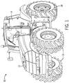
- FIG. 1 is a perspective view of an embodiment of an off-road vehicle 10 (e.g., an agricultural vehicle or work vehicle) that may include the integrated intake and deaeration assembly.
- the off-road vehicle 10 may be a tractor, an off-road vehicle, a work vehicle, or any other suitable vehicle that utilizes a cooling system having a deaeration chamber and an air intake system.
- the off-road vehicle 10 has a body 12 that typically houses an engine, a cooling system, a transmission, and/or a power train.
- the off-road vehicle 10 has a cabin 14 where an operator may sit or stand to operate the off-road vehicle 10.
- the off-road vehicle 10 has two front wheels 16 and two rear wheels 18 that rotate to move the off-road vehicle 10. However, other embodiments may include any number of wheels or tracks to move the off-road vehicle 10. As illustrated, the off-road vehicle 10 is maneuvered using a steering wheel 20 configured to direct the off-road vehicle 10. In certain embodiments, the steering wheel 20 may turn the front wheels 16 (or the rear wheels 18) to control the steering of the off-road vehicle 10.
- the air intake duct and the deaeration chamber may be integrated (e.g., share a common wall) with one another to form a single component.
- the single component may substantially eliminate and/or reduce any gaps present between the air intake duct and the deaeration chamber, thereby reducing an amount of space occupied by the air intake duct and the deaeration chamber.
- establishing more space under the hood of the off-road vehicle 10 may enable the hood to be lowered such that an amount of drag experienced by the off-road vehicle 10 is reduced.
- a single mold may be utilized to form the integrated component as opposed to utilizing two or more molds to form each component separately.
- two molds may be utilized to form the integrated component as opposed to utilizing four or more molds to form each component separately (e.g., each component may be formed using two molds). Utilizing fewer molds may reduce costs for manufacturing the off-road vehicle 10 and integrating the components may improve performance of the off-road vehicle (e.g., by transferring heat between the coolant fluid and intake air). Accordingly, integrating the components into a single integrated intake and deaeration assembly may establish space for additional features to be incorporated into the off-road vehicle 10 as well as reduce manufacturing costs.
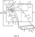
- FIG. 2 is a block diagram of a cooling system 30 and an air intake system 31 that may be utilized in the off-road vehicle 10.
- the air intake system 31 may include an air flow path 32 and the cooling system 30 may include a coolant fluid loop 34.
- Air 36 may be directed along the air flow path 32 toward an integrated intake and deaeration assembly 38 via utilized vacuum created by the engine to move the air 36 along the air flow path 32.
- the air 36 flows through an air intake compartment 40 of the integrated intake and deaeration assembly 38.
- the air intake compartment 40 may be configured to direct the air 36 from an inlet portion 42 of the air intake compartment 40 toward an outlet portion 44 of the air intake compartment 40.
- the air 36 may be received by an engine 46 (e.g., a combustion chamber of the engine 46) after exiting the outlet portion 44 of the air intake compartment 40.
- an engine 46 e.g., a combustion chamber of the engine 46
- the integrated intake and deaeration assembly 38 may be configured to receive coolant 48 from the coolant fluid loop 34.
- the coolant fluid loop 34 includes a radiator 50, a pump 52, a thermostat 54, and the engine 46.
- the radiator 50 functions as a heat exchanger that transfers thermal energy from coolant fluid 48 flowing through the coolant fluid loop 34 to the air, for example. Accordingly, the coolant fluid 48 flowing into the radiator 50 may have a higher temperature than the coolant fluid 48 flowing out of the radiator 50.
- the coolant fluid 48 exiting the radiator 50 is ultimately received by the engine 46 of the off-road vehicle 10 to reduce a temperature of the engine 46 such that the temperature of the engine 46 may be maintained within a desired range during operation.
- the coolant fluid 48 is driven through the coolant fluid loop 34 via the pump 52.
- the pump 52 is located downstream of the radiator 50 and upstream of the engine 46.
- the pump 52 may be positioned in any suitable location along the coolant fluid loop 34.
- the thermostat 54 may monitor a temperature of the engine 46 and/or the coolant fluid 48 and open and/or close a valve to direct the coolant fluid 48 toward the radiator 50 when the temperature of the engine 46 reaches a value outside of the desired temperature range.
- the radiator 50 may cool the coolant fluid 48 such that the coolant fluid 48 may absorb heat from the engine 46, thereby causing the engine 46 to reach a temperature value within the desired temperature range.
- the thermostat 54 may be coupled to a thermocouple that measures a temperature of the engine 46.
- the thermostat 54 may include a material that melts when the engine 46 reaches a temperature outside of the desired temperature range, such that the valve opens and drives the coolant fluid 48 into the radiator 50.
- the thermostat may be configured to direct the coolant fluid 48 through a radiator bypass path 55 when the measured temperature value of the engine 46 is within the desired temperature range, thereby enhancing an efficiency of the cooling system 30.
- the coolant fluid 48 may include air bubbles as a result of flowing through the radiator 50 and/or the engine 46 of the off-road vehicle 10. It may be desirable to substantially eliminate and/or reduce the air bubbles to enhance the efficiency of the pump. Accordingly, the coolant fluid 48 may be directed toward a deaeration compartment 56 (e.g., separated from the intake compartment 40) of the integrated intake and deaeration assembly 38.
- the deaeration compartment 56 may enable any air that may have been present in the coolant fluid 48 to separate from the coolant fluid and either be trapped in a top portion 57 of the deaeration compartment 56 or vented to atmosphere via a pressure relief valve 58.
- the top portion 57 of the deaeration compartment 56 may also include an opening 59.
- the opening 59 may be utilized to add more coolant fluid 48 to the coolant fluid loop 34 and may be capped with the pressure relief valve 58.
- the coolant fluid 48 may be water or a mixture of water and alcohol (e.g., methanol, ethylene glycol, propylene glycol, etc.). Accordingly, as the coolant fluid 48 absorbs thermal energy from the engine 46, a portion of the coolant fluid 48 may evaporate into vapor. As such, as the coolant fluid 48 enters the deaeration compartment 56, some vapor may separate from the liquid coolant fluid and exit the coolant fluid loop 34 via the pressure relief valve 58. Additional coolant fluid 48 may be periodically added to the coolant fluid loop 34 via the opening 59 to ensure that a suitable amount of coolant fluid 48 is present in the coolant fluid loop 34 during operation of the engine 46.
- the deaeration compartment 56 also includes a first inlet port 60 and a second inlet port 62.
- the first and second inlet ports 60, 62 are configured to receive coolant fluid 48 into the deaeration compartment 56.
- the first inlet port 60 may enable coolant fluid 48 from the radiator 50 (e.g., exiting an inlet tank of the radiator 50) to enter the deaeration compartment 56.
- the second inlet port 62 may receive coolant fluid 48 from the engine 46.
- air bubbles that may be present in the coolant fluid 48 may separate, thereby enhancing an efficiency of the cooling system 30.
- the deaeration compartment 56 also includes an outlet port 64.
- the coolant fluid 48 that collects in the deaeration compartment 56 flows through the outlet port 64 to the pump 52.
- the pump 52 receives the coolant fluid 48 (e.g., coolant fluid substantially free of air bubbles) and directs the coolant fluid 48 toward the engine 46 (e.g., when the thermostat valve is open).
- the coolant fluid 48 may then absorb thermal energy from the engine 46 to maintain the engine 46 within the desired temperature range during engine operation.
- the cooling system 30 may include a cab heater 66.
- the cab heater 66 may be a heat exchange device configured to transfer heat to the cabin 14 of the off-road vehicle 10. Accordingly, warm coolant fluid 48 exiting the engine 46 may be directed toward the cab heater 66 where heat may be transferred from the coolant fluid 48 to air or another medium that may be utilized to heat or warm the cabin 14.
- the cab heater 66 may enhance an efficiency of the cooling system 30 by providing excess heat to the cabin 14 during cold weather rather than allowing such heat to escape to the atmosphere.
- integrating the intake air duct (e.g., the intake compartment 40) and the deaeration chamber (e.g., the deaeration compartment 56) into a single component may establish additional space for features under the hood of the off-road vehicle 10, as well as decrease manufacturing costs of the off-road vehicle 10.
- a single mold may be utilized to form the integrated component as opposed to utilizing two or more molds to form each component separately.
- two molds may be utilized to form the integrated component as opposed to utilizing four or more molds to form each component separately (e.g., each component may be formed using two molds).
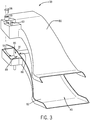
- the integrated component may include a first portion 80 of the integrated intake and deaeration assembly 38 and a second portion 82 of the integrated intake and deaeration assembly 38, as shown in FIG. 3 .
- FIG. 3 is an exploded perspective view of the integrated intake and deaeration assembly 38 and illustrates how the integrated intake and deaeration assembly 38 may be assembled.
- the integrated intake and deaeration assembly 38 may include a single component, and thus may not have the first portion 80 and the second portion 82 (e.g., when a single mold may be used to form the integrated intake and deaeration assembly 38)
- the first and second portions 80, 82 (e.g., first and second components) of the integrated intake and deaeration assembly 38 form the intake compartment 40 and the deaeration compartment 56.
- the intake compartment 40 and the deaeration compartment 56 are separated by a shared wall 84.
- the shared wall 84 includes a section that is part of the first portion 80 of the integrated intake and deaeration assembly 38.
- the shared wall 84 includes a second section 85 that is part of the second portion 82 of the integrated intake and deaeration assembly 38.
- the first section and the second section 85 of the shared wall 84 may be configured to be substantially aligned with one another such that the shared wall 84 is substantially smooth (e.g., ends of the first section and the second section 85 of the shared wall 84 align with one another) when the first and second portions 80, 82 of the integrated intake and deaeration assembly 38 are coupled to one another.
- the shared wall 84 includes a first surface 86 that faces the intake compartment 40 and forms a portion of the intake compartment 40 (e.g., the first surface 86 of the shared wall 84 forms a portion of a wall of the intake compartment 40). Additionally, the shared wall 84 includes a second surface 88 that faces the deaeration compartment 56 and forms a portion of the deaeration compartment 56 (e.g., the second surface 88 of the shared wall 84 forms a portion of a wall of the deaeration compartment 56).
- the intake compartment 40 and the deaeration compartment 56 may be sealed such that fluid flow (e.g., air, coolant fluid, etc.) is blocked between the intake compartment 40 and the deaeration compartment 56.
- fluid flow e.g., air, coolant fluid, etc.
- the first portion 80 and the second portion 82 of the integrated intake and deaeration assembly 38 may be coupled to one another in a manner that facilitates a substantially fluid-tight connection.
- the first portion 80 and the second portion 82 may be laser welded to one another.
- the first portion 80 and/or the second portion 82 may partially melt and re-harden, such that the first portion 80 adheres to the second portion 82, thereby establishing a seal between the portions.
- the first portion 80 and the second portion 82 may be coupled to one another via fasteners (e.g., screws, bolts, rivets, etc.).
- the fasteners may couple the first portion 80 and the second portion 82 to one another, while substantially eliminating gaps and/or openings between the first portion 80 and the second portion 82, thereby establishing a seal between the portions.
- FIG. 4 is a cross-sectional perspective view of the integrated intake and deaeration assembly 38, in which the first portion 80 and the second portion 82 (and thus the first section and the second section 85 of the shared wall 84) are coupled to one another. As shown in the illustrated embodiment of FIG. 4 , the first portion 80 and the second portion 82 form the intake compartment 40 and the deaeration compartment 56 via the shared wall 84.
- the intake compartment 40 includes a cross-section that is substantially rectangular. In other embodiments, the intake compartment 40 may have a cross-section that includes any suitable shape for directing air toward the engine 46 (e.g., square, circular). Additionally, the cross-section of the intake compartment 40 may be substantially uniform along a length of the intake compartment 40 (e.g., from the inlet portion 42 to the outlet portion 44). In other embodiments, the cross-section of the intake compartment 40 may vary along the length of the intake compartment 40. Further, as illustrated, the intake compartment 40 includes the outlet portion 44 that directs the air 36 toward the engine 46.
- the deaeration compartment 56 has a cross-section that is substantially rectangular.
- the rectangular cross-section forms a chamber 90 in which the coolant fluid 48 may collect.
- the deaeration compartment 56 may include any suitable shape that may enable the coolant fluid 48 to collect in the chamber 90 and to facilitate removal of air bubbles from the coolant fluid 48.
- the chamber 90 enables air bubbles present within the coolant fluid 48 to separate and exit the deaeration compartment 56 via the pressure relief valve 58 (and the opening 59).
- the pressure relief valve 58 may include a spring-loaded valve. The spring-loaded valve may be biased toward a closed position, thereby trapping separated gas inside of the deaeration component.
- the pressure relief valve 58 may include any suitable valve that may be utilized to control a flow of gas that may be released from the deaeration compartment 56.
- the deaeration compartment 56 includes the first inlet port 60 and the second inlet port 62.
- the first inlet port 60 may be coupled to a flow path extending from the radiator 50 and configured to receive cooled coolant fluid 48 from the radiator 50.
- the second inlet port 62 may be coupled to the engine bypass path 55 and configured to receive the coolant fluid 48 bypassing the radiator 50.
- the outlet port 64 is located on a bottom surface 92 of the deaeration compartment 56. The outlet port 64 is configured to direct the coolant fluid 48 toward the pump 52, which is configured to circulate the coolant fluid 48 throughout the coolant fluid loop 34. It should be noted that in other embodiments, the outlet port 64 may be located in any suitable location in the deaeration compartment for directing the coolant fluid 48 toward the pump 52.
- the shared wall 84 extends between the intake compartment 40 and the deaeration compartment 56.
- the shared wall 84 is formed by aligning and coupling the first section 89 and the second section 85 of the shared wall 84.
- the shared wall 84 (e.g., when the first section 89 and the second section 85 are coupled to one another) includes the first surface 86 facing the intake compartment 40 and the second surface 88 facing the deaeration compartment 56. Accordingly, the shared wall 84 may substantially eliminate any gaps between the intake compartment 40 and the deaeration compartment 56. The elimination of such gaps may reduce an amount of space occupied by the integrated intake and deaeration assembly 38, as compared to a separate intake air duct and deaeration chamber. Consequently, additional components may fit under the hood of the off-road vehicle 10. Additionally or alternatively, the hood of the off-road vehicle 10 may be lowered as a result of the increased space, such that an amount of drag experienced by the off-road vehicle is reduced.
- the shared wall 84 also facilitates a transfer of thermal energy between the air 36 in the intake compartment 40 and the coolant fluid 48 in the deaeration compartment 56.
- the temperature of the coolant fluid 48 in the deaeration compartment 56 may be greater than a temperature of the air 36 in the intake compartment 40. Accordingly, thermal energy may be transferred from the coolant fluid 48 to the air 36 via the shared wall 84.
- the thickness of the shared wall 84 may be particularly selected to facilitate thermal energy transfer while establishing a substantially fluid-tight seal between the intake compartment 40 and the deaeration compartment 56.
- the thickness of the shared wall 84 may be selected to insulate the intake compartment 40 from the deaeration compartment 56 (e.g., the thickness reduces the transfer of thermal energy between the deaeration compartment 56 and the intake compartment 56). It should be noted that while the thickness of the shared wall 84 may be increased to insulate the intake compartment 40 from the deaeration compartment 56, the thickness may still be substantially smaller than any gaps present between a separate intake air duct and deaeration chamber.
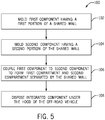
- FIG. 5 is a flow diagram of a method 100 for manufacturing the integrated intake and deaeration assembly.
- the first portion e.g., a first component
- the first portion may be formed from a polymeric material such as polypropylene, nylon, or another suitable polymeric material.
- the first portion e.g., the first component
- the first portion may include the first section of the shared wall.
- the second portion may include the second section of the shared wall.
- the second portion (e.g., a second component) of the integrated intake and deaeration assembly is formed (e.g., via injection molding).
- the second portion e.g., the second component
- the second portion may be formed from a polymeric material such as polypropylene, nylon, or another suitable polymeric material.
- the first and second portions are coupled to one another to form the integrated intake and deaeration assembly, as shown at block 106.
- the first and second portion e.g., the first and second components
- the intake compartment e.g., a first compartment
- the deaeration compartment e.g., a second compartment
- the first and second portions may be coupled to one another by laser welding the first portion to the second portion of the integrated intake and deaeration assembly.
- first and second portions may be coupled to one another via fasteners (e.g., screws, bolts, rivets, etc.).
- first and second portions are configured to form a substantially fluid-tight seal such that the intake compartment (e.g., the first compartment) and the deaeration compartment (e.g., the second compartment) are substantially fluidly isolated from one another (e.g., air from the intake compartment may be substantially blocked from entering the deaeration compartment, and/or coolant fluid from the deaeration compartment may be substantially blocked from entering the intake compartment).
- the integrated intake and deaeration assembly is disposed underneath the hood of the off-road vehicle.
- the integrated intake and deaeration assembly may reduce an amount of space occupied under the hood, as compared to a separate intake air duct and deaeration chamber. Accordingly, additional components may be included underneath the hood of the off-road vehicle. Additionally or alternatively, the hood of the off-road vehicle 10 may be lowered as a result of the increased space, such that an amount of drag experienced by the off-road vehicle is reduced.
Applications Claiming Priority (1)
| Application Number | Priority Date | Filing Date | Title |
|---|---|---|---|
| US14/921,783 US20170114704A1 (en) | 2015-10-23 | 2015-10-23 | Integrated intake and deaeration assembly for a work vehicle |
Publications (2)
| Publication Number | Publication Date |
|---|---|
| EP3159201A1 true EP3159201A1 (de) | 2017-04-26 |
| EP3159201B1 EP3159201B1 (de) | 2020-10-21 |
Family
ID=57189894
Family Applications (1)
| Application Number | Title | Priority Date | Filing Date |
|---|---|---|---|
| EP16195126.4A Active EP3159201B1 (de) | 2015-10-23 | 2016-10-21 | Integrierte einlass- und entlüftungsanordnung für ein nutzfahrzeug |
Country Status (4)
| Country | Link |
|---|---|
| US (1) | US20170114704A1 (de) |
| EP (1) | EP3159201B1 (de) |
| CN (1) | CN206495713U (de) |
| BR (1) | BR102016024487B1 (de) |
Families Citing this family (7)
| Publication number | Priority date | Publication date | Assignee | Title |
|---|---|---|---|---|
| USD1025132S1 (en) * | 2019-08-26 | 2024-04-30 | Velossa Tech Engineering Inc. | Ram-air intake |
| USD1009936S1 (en) * | 2019-08-26 | 2024-01-02 | Velossa Tech Engineering Inc. | Ram-air intake |
| USD1019704S1 (en) | 2020-02-09 | 2024-03-26 | Velossa Tech Engineering, Inc. | Ram-air intake |
| USD1023061S1 (en) * | 2020-02-09 | 2024-04-16 | Velossa Tech Engineering, Inc. | Ram-air intake |
| US20210246855A1 (en) | 2020-02-09 | 2021-08-12 | Velossa Tech Engineering Inc. | Interchangeable intake manifold assemblies |
| USD993282S1 (en) * | 2021-06-11 | 2023-07-25 | Velossa Tech Engineering Inc. | Ram-air intake |
| USD992601S1 (en) * | 2021-06-11 | 2023-07-18 | Velossa Tech Engineering Inc. | Ram-air intake |
Citations (4)
| Publication number | Priority date | Publication date | Assignee | Title |
|---|---|---|---|---|
| US6247442B1 (en) * | 1999-11-19 | 2001-06-19 | Polaris Industries Inc. | Combined air box, coolant reservoir and oil tank for snowmobiles |
| US20020071571A1 (en) * | 2000-09-20 | 2002-06-13 | Siemens Vdo Automotive, Inc. | Integrated active noise attenuation system and fluid reservoir |
| EP1607616A2 (de) * | 2004-06-14 | 2005-12-21 | Mann+Hummel Gmbh | Filtergehäuse mit Resonator und Reservoir |
| US7191739B1 (en) * | 2005-12-06 | 2007-03-20 | Ford Global Technologies, Llc | Integral coolant reservoir and air cleaner for automotive vehicle |
Family Cites Families (1)
| Publication number | Priority date | Publication date | Assignee | Title |
|---|---|---|---|---|
| US4098328A (en) * | 1977-06-16 | 1978-07-04 | Borg-Warner Corporation | Cross-flow radiator deaeration system |
-
2015
- 2015-10-23 US US14/921,783 patent/US20170114704A1/en not_active Abandoned
-
2016
- 2016-09-29 CN CN201621092462.1U patent/CN206495713U/zh not_active Expired - Fee Related
- 2016-10-20 BR BR102016024487-0A patent/BR102016024487B1/pt active IP Right Grant
- 2016-10-21 EP EP16195126.4A patent/EP3159201B1/de active Active
Patent Citations (4)
| Publication number | Priority date | Publication date | Assignee | Title |
|---|---|---|---|---|
| US6247442B1 (en) * | 1999-11-19 | 2001-06-19 | Polaris Industries Inc. | Combined air box, coolant reservoir and oil tank for snowmobiles |
| US20020071571A1 (en) * | 2000-09-20 | 2002-06-13 | Siemens Vdo Automotive, Inc. | Integrated active noise attenuation system and fluid reservoir |
| EP1607616A2 (de) * | 2004-06-14 | 2005-12-21 | Mann+Hummel Gmbh | Filtergehäuse mit Resonator und Reservoir |
| US7191739B1 (en) * | 2005-12-06 | 2007-03-20 | Ford Global Technologies, Llc | Integral coolant reservoir and air cleaner for automotive vehicle |
Also Published As
| Publication number | Publication date |
|---|---|
| BR102016024487A2 (pt) | 2017-07-18 |
| EP3159201B1 (de) | 2020-10-21 |
| BR102016024487B1 (pt) | 2023-05-16 |
| CN206495713U (zh) | 2017-09-15 |
| US20170114704A1 (en) | 2017-04-27 |
Similar Documents
| Publication | Publication Date | Title |
|---|---|---|
| EP3159201B1 (de) | Integrierte einlass- und entlüftungsanordnung für ein nutzfahrzeug | |
| EP2602143B1 (de) | Kühlstruktur für fahrzeuge | |
| EP2663753B1 (de) | System und verfahren zur wärmeverwaltung | |
| CN102312715B (zh) | 燃料高效的动力系冷却系统和散热器模块 | |
| EP2565069B1 (de) | Kühlluftstrom-einlassstruktur | |
| EP2686184B1 (de) | Kühlkreislauf für ein elektrisches hybridfahrzeug und verfahren zur kühlung | |
| CN205714398U (zh) | 发动机冷却液流量控制阀、发动机冷却系统以及汽车 | |
| JP2008516176A (ja) | 空気冷却される排ガス熱伝達体、特に自動車のための排ガスクーラー | |
| US20130316634A1 (en) | Cooling wind introduction structure | |
| CN204646399U (zh) | 一种发动机冷却系统及发动机 | |
| US10253679B2 (en) | Vehicle thermal management system, and methods of use and manufacture thereof | |
| KR101601409B1 (ko) | 차량 공조 시스템의 열 교환기를 위한 유체 관리 시스템 | |
| US20070227474A1 (en) | Optimized Cooling System for a Motorized Vehicle | |
| US11125190B2 (en) | Methods and system for an engine system | |
| US11602985B2 (en) | Continuous cooling assembly | |
| CN109386368A (zh) | 发动机的冷却装置 | |
| US10717344B2 (en) | Heating and cooling system for a vehicle | |
| CN109296444B (zh) | 冷却系统和机动车 | |
| EP2990624A1 (de) | Hlk-system für ein arbeitsfahrzeug | |
| CN206267950U (zh) | 冷却增压空气和过剩燃料的系统及其工作车辆 | |
| EP2212530B1 (de) | Kühlanordnung für eni nutzfahrzeug | |
| CN212079449U (zh) | 一种调温器总成、发动机及汽车 | |
| EP2578838A1 (de) | Kühlsystem für einen Motor | |
| US9828901B2 (en) | Engine assembly including a coolant gallery | |
| US20230387752A1 (en) | Cooling system for an electric traction machine for a motor vehicle |
Legal Events
| Date | Code | Title | Description |
|---|---|---|---|
| PUAI | Public reference made under article 153(3) epc to a published international application that has entered the european phase |
Free format text: ORIGINAL CODE: 0009012 |
|
| STAA | Information on the status of an ep patent application or granted ep patent |
Free format text: STATUS: THE APPLICATION HAS BEEN PUBLISHED |
|
| AK | Designated contracting states |
Kind code of ref document: A1 Designated state(s): AL AT BE BG CH CY CZ DE DK EE ES FI FR GB GR HR HU IE IS IT LI LT LU LV MC MK MT NL NO PL PT RO RS SE SI SK SM TR |
|
| AX | Request for extension of the european patent |
Extension state: BA ME |
|
| STAA | Information on the status of an ep patent application or granted ep patent |
Free format text: STATUS: REQUEST FOR EXAMINATION WAS MADE |
|
| 17P | Request for examination filed |
Effective date: 20171026 |
|
| RBV | Designated contracting states (corrected) |
Designated state(s): AL AT BE BG CH CY CZ DE DK EE ES FI FR GB GR HR HU IE IS IT LI LT LU LV MC MK MT NL NO PL PT RO RS SE SI SK SM TR |
|
| STAA | Information on the status of an ep patent application or granted ep patent |
Free format text: STATUS: EXAMINATION IS IN PROGRESS |
|
| 17Q | First examination report despatched |
Effective date: 20190311 |
|
| GRAP | Despatch of communication of intention to grant a patent |
Free format text: ORIGINAL CODE: EPIDOSNIGR1 |
|
| STAA | Information on the status of an ep patent application or granted ep patent |
Free format text: STATUS: GRANT OF PATENT IS INTENDED |
|
| INTG | Intention to grant announced |
Effective date: 20200504 |
|
| GRAS | Grant fee paid |
Free format text: ORIGINAL CODE: EPIDOSNIGR3 |
|
| GRAA | (expected) grant |
Free format text: ORIGINAL CODE: 0009210 |
|
| STAA | Information on the status of an ep patent application or granted ep patent |
Free format text: STATUS: THE PATENT HAS BEEN GRANTED |
|
| AK | Designated contracting states |
Kind code of ref document: B1 Designated state(s): AL AT BE BG CH CY CZ DE DK EE ES FI FR GB GR HR HU IE IS IT LI LT LU LV MC MK MT NL NO PL PT RO RS SE SI SK SM TR |
|
| REG | Reference to a national code |
Ref country code: GB Ref legal event code: FG4D |
|
| REG | Reference to a national code |
Ref country code: CH Ref legal event code: EP |
|
| REG | Reference to a national code |
Ref country code: DE Ref legal event code: R096 Ref document number: 602016046132 Country of ref document: DE |
|
| REG | Reference to a national code |
Ref country code: IE Ref legal event code: FG4D |
|
| REG | Reference to a national code |
Ref country code: AT Ref legal event code: REF Ref document number: 1325488 Country of ref document: AT Kind code of ref document: T Effective date: 20201115 |
|
| REG | Reference to a national code |
Ref country code: AT Ref legal event code: MK05 Ref document number: 1325488 Country of ref document: AT Kind code of ref document: T Effective date: 20201021 |
|
| REG | Reference to a national code |
Ref country code: NL Ref legal event code: MP Effective date: 20201021 |
|
| PG25 | Lapsed in a contracting state [announced via postgrant information from national office to epo] |
Ref country code: NL Free format text: LAPSE BECAUSE OF FAILURE TO SUBMIT A TRANSLATION OF THE DESCRIPTION OR TO PAY THE FEE WITHIN THE PRESCRIBED TIME-LIMIT Effective date: 20201021 Ref country code: NO Free format text: LAPSE BECAUSE OF FAILURE TO SUBMIT A TRANSLATION OF THE DESCRIPTION OR TO PAY THE FEE WITHIN THE PRESCRIBED TIME-LIMIT Effective date: 20210121 Ref country code: PT Free format text: LAPSE BECAUSE OF FAILURE TO SUBMIT A TRANSLATION OF THE DESCRIPTION OR TO PAY THE FEE WITHIN THE PRESCRIBED TIME-LIMIT Effective date: 20210222 Ref country code: RS Free format text: LAPSE BECAUSE OF FAILURE TO SUBMIT A TRANSLATION OF THE DESCRIPTION OR TO PAY THE FEE WITHIN THE PRESCRIBED TIME-LIMIT Effective date: 20201021 Ref country code: GR Free format text: LAPSE BECAUSE OF FAILURE TO SUBMIT A TRANSLATION OF THE DESCRIPTION OR TO PAY THE FEE WITHIN THE PRESCRIBED TIME-LIMIT Effective date: 20210122 Ref country code: FI Free format text: LAPSE BECAUSE OF FAILURE TO SUBMIT A TRANSLATION OF THE DESCRIPTION OR TO PAY THE FEE WITHIN THE PRESCRIBED TIME-LIMIT Effective date: 20201021 |
|
| REG | Reference to a national code |
Ref country code: LT Ref legal event code: MG4D |
|
| PG25 | Lapsed in a contracting state [announced via postgrant information from national office to epo] |
Ref country code: SE Free format text: LAPSE BECAUSE OF FAILURE TO SUBMIT A TRANSLATION OF THE DESCRIPTION OR TO PAY THE FEE WITHIN THE PRESCRIBED TIME-LIMIT Effective date: 20201021 Ref country code: BG Free format text: LAPSE BECAUSE OF FAILURE TO SUBMIT A TRANSLATION OF THE DESCRIPTION OR TO PAY THE FEE WITHIN THE PRESCRIBED TIME-LIMIT Effective date: 20210121 Ref country code: LV Free format text: LAPSE BECAUSE OF FAILURE TO SUBMIT A TRANSLATION OF THE DESCRIPTION OR TO PAY THE FEE WITHIN THE PRESCRIBED TIME-LIMIT Effective date: 20201021 Ref country code: PL Free format text: LAPSE BECAUSE OF FAILURE TO SUBMIT A TRANSLATION OF THE DESCRIPTION OR TO PAY THE FEE WITHIN THE PRESCRIBED TIME-LIMIT Effective date: 20201021 Ref country code: IS Free format text: LAPSE BECAUSE OF FAILURE TO SUBMIT A TRANSLATION OF THE DESCRIPTION OR TO PAY THE FEE WITHIN THE PRESCRIBED TIME-LIMIT Effective date: 20210221 Ref country code: AT Free format text: LAPSE BECAUSE OF FAILURE TO SUBMIT A TRANSLATION OF THE DESCRIPTION OR TO PAY THE FEE WITHIN THE PRESCRIBED TIME-LIMIT Effective date: 20201021 Ref country code: ES Free format text: LAPSE BECAUSE OF FAILURE TO SUBMIT A TRANSLATION OF THE DESCRIPTION OR TO PAY THE FEE WITHIN THE PRESCRIBED TIME-LIMIT Effective date: 20201021 |
|
| REG | Reference to a national code |
Ref country code: CH Ref legal event code: PL |
|
| REG | Reference to a national code |
Ref country code: DE Ref legal event code: R082 Ref document number: 602016046132 Country of ref document: DE Representative=s name: KROHER STROBEL RECHTS- UND PATENTANWAELTE PART, DE |
|
| PG25 | Lapsed in a contracting state [announced via postgrant information from national office to epo] |
Ref country code: HR Free format text: LAPSE BECAUSE OF FAILURE TO SUBMIT A TRANSLATION OF THE DESCRIPTION OR TO PAY THE FEE WITHIN THE PRESCRIBED TIME-LIMIT Effective date: 20201021 Ref country code: LU Free format text: LAPSE BECAUSE OF NON-PAYMENT OF DUE FEES Effective date: 20201021 |
|
| REG | Reference to a national code |
Ref country code: BE Ref legal event code: MM Effective date: 20201031 |
|
| REG | Reference to a national code |
Ref country code: DE Ref legal event code: R097 Ref document number: 602016046132 Country of ref document: DE |
|
| PG25 | Lapsed in a contracting state [announced via postgrant information from national office to epo] |
Ref country code: SK Free format text: LAPSE BECAUSE OF FAILURE TO SUBMIT A TRANSLATION OF THE DESCRIPTION OR TO PAY THE FEE WITHIN THE PRESCRIBED TIME-LIMIT Effective date: 20201021 Ref country code: RO Free format text: LAPSE BECAUSE OF FAILURE TO SUBMIT A TRANSLATION OF THE DESCRIPTION OR TO PAY THE FEE WITHIN THE PRESCRIBED TIME-LIMIT Effective date: 20201021 Ref country code: CZ Free format text: LAPSE BECAUSE OF FAILURE TO SUBMIT A TRANSLATION OF THE DESCRIPTION OR TO PAY THE FEE WITHIN THE PRESCRIBED TIME-LIMIT Effective date: 20201021 Ref country code: EE Free format text: LAPSE BECAUSE OF FAILURE TO SUBMIT A TRANSLATION OF THE DESCRIPTION OR TO PAY THE FEE WITHIN THE PRESCRIBED TIME-LIMIT Effective date: 20201021 Ref country code: SM Free format text: LAPSE BECAUSE OF FAILURE TO SUBMIT A TRANSLATION OF THE DESCRIPTION OR TO PAY THE FEE WITHIN THE PRESCRIBED TIME-LIMIT Effective date: 20201021 Ref country code: LT Free format text: LAPSE BECAUSE OF FAILURE TO SUBMIT A TRANSLATION OF THE DESCRIPTION OR TO PAY THE FEE WITHIN THE PRESCRIBED TIME-LIMIT Effective date: 20201021 Ref country code: MC Free format text: LAPSE BECAUSE OF FAILURE TO SUBMIT A TRANSLATION OF THE DESCRIPTION OR TO PAY THE FEE WITHIN THE PRESCRIBED TIME-LIMIT Effective date: 20201021 |
|
| PLBE | No opposition filed within time limit |
Free format text: ORIGINAL CODE: 0009261 |
|
| STAA | Information on the status of an ep patent application or granted ep patent |
Free format text: STATUS: NO OPPOSITION FILED WITHIN TIME LIMIT |
|
| PG25 | Lapsed in a contracting state [announced via postgrant information from national office to epo] |
Ref country code: DK Free format text: LAPSE BECAUSE OF FAILURE TO SUBMIT A TRANSLATION OF THE DESCRIPTION OR TO PAY THE FEE WITHIN THE PRESCRIBED TIME-LIMIT Effective date: 20201021 Ref country code: BE Free format text: LAPSE BECAUSE OF NON-PAYMENT OF DUE FEES Effective date: 20201031 Ref country code: CH Free format text: LAPSE BECAUSE OF NON-PAYMENT OF DUE FEES Effective date: 20201031 Ref country code: LI Free format text: LAPSE BECAUSE OF NON-PAYMENT OF DUE FEES Effective date: 20201031 |
|
| 26N | No opposition filed |
Effective date: 20210722 |
|
| GBPC | Gb: european patent ceased through non-payment of renewal fee |
Effective date: 20210121 |
|
| PG25 | Lapsed in a contracting state [announced via postgrant information from national office to epo] |
Ref country code: IE Free format text: LAPSE BECAUSE OF NON-PAYMENT OF DUE FEES Effective date: 20201021 Ref country code: AL Free format text: LAPSE BECAUSE OF FAILURE TO SUBMIT A TRANSLATION OF THE DESCRIPTION OR TO PAY THE FEE WITHIN THE PRESCRIBED TIME-LIMIT Effective date: 20201021 |
|
| PG25 | Lapsed in a contracting state [announced via postgrant information from national office to epo] |
Ref country code: SI Free format text: LAPSE BECAUSE OF FAILURE TO SUBMIT A TRANSLATION OF THE DESCRIPTION OR TO PAY THE FEE WITHIN THE PRESCRIBED TIME-LIMIT Effective date: 20201021 Ref country code: GB Free format text: LAPSE BECAUSE OF NON-PAYMENT OF DUE FEES Effective date: 20210121 |
|
| PG25 | Lapsed in a contracting state [announced via postgrant information from national office to epo] |
Ref country code: IS Free format text: LAPSE BECAUSE OF FAILURE TO SUBMIT A TRANSLATION OF THE DESCRIPTION OR TO PAY THE FEE WITHIN THE PRESCRIBED TIME-LIMIT Effective date: 20210221 Ref country code: TR Free format text: LAPSE BECAUSE OF FAILURE TO SUBMIT A TRANSLATION OF THE DESCRIPTION OR TO PAY THE FEE WITHIN THE PRESCRIBED TIME-LIMIT Effective date: 20201021 Ref country code: MT Free format text: LAPSE BECAUSE OF FAILURE TO SUBMIT A TRANSLATION OF THE DESCRIPTION OR TO PAY THE FEE WITHIN THE PRESCRIBED TIME-LIMIT Effective date: 20201021 Ref country code: CY Free format text: LAPSE BECAUSE OF FAILURE TO SUBMIT A TRANSLATION OF THE DESCRIPTION OR TO PAY THE FEE WITHIN THE PRESCRIBED TIME-LIMIT Effective date: 20201021 |
|
| PG25 | Lapsed in a contracting state [announced via postgrant information from national office to epo] |
Ref country code: MK Free format text: LAPSE BECAUSE OF FAILURE TO SUBMIT A TRANSLATION OF THE DESCRIPTION OR TO PAY THE FEE WITHIN THE PRESCRIBED TIME-LIMIT Effective date: 20201021 |
|
| PGFP | Annual fee paid to national office [announced via postgrant information from national office to epo] |
Ref country code: IT Payment date: 20231004 Year of fee payment: 8 Ref country code: FR Payment date: 20231024 Year of fee payment: 8 Ref country code: DE Payment date: 20231030 Year of fee payment: 8 |