EP3158909A1 - Guide apparatus and surgery system - Google Patents
Guide apparatus and surgery system Download PDFInfo
- Publication number
- EP3158909A1 EP3158909A1 EP15809885.5A EP15809885A EP3158909A1 EP 3158909 A1 EP3158909 A1 EP 3158909A1 EP 15809885 A EP15809885 A EP 15809885A EP 3158909 A1 EP3158909 A1 EP 3158909A1
- Authority
- EP
- European Patent Office
- Prior art keywords
- flexible section
- section
- channel tube
- guiding device
- proximal end
- Prior art date
- Legal status (The legal status is an assumption and is not a legal conclusion. Google has not performed a legal analysis and makes no representation as to the accuracy of the status listed.)
- Granted
Links
- 238000001356 surgical procedure Methods 0.000 title description 3
- 238000005452 bending Methods 0.000 claims abstract description 41
- 238000003780 insertion Methods 0.000 claims description 27
- 230000037431 insertion Effects 0.000 claims description 27
- 230000002093 peripheral effect Effects 0.000 description 8
- 238000012986 modification Methods 0.000 description 6
- 230000004048 modification Effects 0.000 description 6
- 210000002429 large intestine Anatomy 0.000 description 5
- 238000005096 rolling process Methods 0.000 description 3
- 230000002452 interceptive effect Effects 0.000 description 2
- XLYOFNOQVPJJNP-UHFFFAOYSA-N water Substances O XLYOFNOQVPJJNP-UHFFFAOYSA-N 0.000 description 2
- 206010003011 Appendicitis Diseases 0.000 description 1
- 210000000436 anus Anatomy 0.000 description 1
- 238000004140 cleaning Methods 0.000 description 1
- 239000012141 concentrate Substances 0.000 description 1
- 230000000694 effects Effects 0.000 description 1
- 230000003252 repetitive effect Effects 0.000 description 1
Images



Classifications
-
- A—HUMAN NECESSITIES
- A61—MEDICAL OR VETERINARY SCIENCE; HYGIENE
- A61B—DIAGNOSIS; SURGERY; IDENTIFICATION
- A61B1/00—Instruments for performing medical examinations of the interior of cavities or tubes of the body by visual or photographical inspection, e.g. endoscopes; Illuminating arrangements therefor
- A61B1/005—Flexible endoscopes
- A61B1/01—Guiding arrangements therefore
-
- A—HUMAN NECESSITIES
- A61—MEDICAL OR VETERINARY SCIENCE; HYGIENE
- A61B—DIAGNOSIS; SURGERY; IDENTIFICATION
- A61B1/00—Instruments for performing medical examinations of the interior of cavities or tubes of the body by visual or photographical inspection, e.g. endoscopes; Illuminating arrangements therefor
- A61B1/00002—Operational features of endoscopes
- A61B1/00004—Operational features of endoscopes characterised by electronic signal processing
- A61B1/00006—Operational features of endoscopes characterised by electronic signal processing of control signals
-
- A—HUMAN NECESSITIES
- A61—MEDICAL OR VETERINARY SCIENCE; HYGIENE
- A61B—DIAGNOSIS; SURGERY; IDENTIFICATION
- A61B1/00—Instruments for performing medical examinations of the interior of cavities or tubes of the body by visual or photographical inspection, e.g. endoscopes; Illuminating arrangements therefor
- A61B1/00064—Constructional details of the endoscope body
- A61B1/00071—Insertion part of the endoscope body
-
- A—HUMAN NECESSITIES
- A61—MEDICAL OR VETERINARY SCIENCE; HYGIENE
- A61B—DIAGNOSIS; SURGERY; IDENTIFICATION
- A61B1/00—Instruments for performing medical examinations of the interior of cavities or tubes of the body by visual or photographical inspection, e.g. endoscopes; Illuminating arrangements therefor
- A61B1/00112—Connection or coupling means
- A61B1/00121—Connectors, fasteners and adapters, e.g. on the endoscope handle
- A61B1/00128—Connectors, fasteners and adapters, e.g. on the endoscope handle mechanical, e.g. for tubes or pipes
-
- A—HUMAN NECESSITIES
- A61—MEDICAL OR VETERINARY SCIENCE; HYGIENE
- A61B—DIAGNOSIS; SURGERY; IDENTIFICATION
- A61B1/00—Instruments for performing medical examinations of the interior of cavities or tubes of the body by visual or photographical inspection, e.g. endoscopes; Illuminating arrangements therefor
- A61B1/00147—Holding or positioning arrangements
- A61B1/00154—Holding or positioning arrangements using guiding arrangements for insertion
-
- A—HUMAN NECESSITIES
- A61—MEDICAL OR VETERINARY SCIENCE; HYGIENE
- A61B—DIAGNOSIS; SURGERY; IDENTIFICATION
- A61B1/00—Instruments for performing medical examinations of the interior of cavities or tubes of the body by visual or photographical inspection, e.g. endoscopes; Illuminating arrangements therefor
- A61B1/005—Flexible endoscopes
- A61B1/0051—Flexible endoscopes with controlled bending of insertion part
- A61B1/0052—Constructional details of control elements, e.g. handles
-
- A—HUMAN NECESSITIES
- A61—MEDICAL OR VETERINARY SCIENCE; HYGIENE
- A61B—DIAGNOSIS; SURGERY; IDENTIFICATION
- A61B1/00—Instruments for performing medical examinations of the interior of cavities or tubes of the body by visual or photographical inspection, e.g. endoscopes; Illuminating arrangements therefor
- A61B1/005—Flexible endoscopes
- A61B1/0051—Flexible endoscopes with controlled bending of insertion part
- A61B1/0055—Constructional details of insertion parts, e.g. vertebral elements
-
- A—HUMAN NECESSITIES
- A61—MEDICAL OR VETERINARY SCIENCE; HYGIENE
- A61B—DIAGNOSIS; SURGERY; IDENTIFICATION
- A61B1/00—Instruments for performing medical examinations of the interior of cavities or tubes of the body by visual or photographical inspection, e.g. endoscopes; Illuminating arrangements therefor
- A61B1/012—Instruments for performing medical examinations of the interior of cavities or tubes of the body by visual or photographical inspection, e.g. endoscopes; Illuminating arrangements therefor characterised by internal passages or accessories therefor
- A61B1/0125—Endoscope within endoscope
-
- A—HUMAN NECESSITIES
- A61—MEDICAL OR VETERINARY SCIENCE; HYGIENE
- A61B—DIAGNOSIS; SURGERY; IDENTIFICATION
- A61B1/00—Instruments for performing medical examinations of the interior of cavities or tubes of the body by visual or photographical inspection, e.g. endoscopes; Illuminating arrangements therefor
- A61B1/012—Instruments for performing medical examinations of the interior of cavities or tubes of the body by visual or photographical inspection, e.g. endoscopes; Illuminating arrangements therefor characterised by internal passages or accessories therefor
- A61B1/018—Instruments for performing medical examinations of the interior of cavities or tubes of the body by visual or photographical inspection, e.g. endoscopes; Illuminating arrangements therefor characterised by internal passages or accessories therefor for receiving instruments
-
- A—HUMAN NECESSITIES
- A61—MEDICAL OR VETERINARY SCIENCE; HYGIENE
- A61B—DIAGNOSIS; SURGERY; IDENTIFICATION
- A61B17/00—Surgical instruments, devices or methods
- A61B17/00234—Surgical instruments, devices or methods for minimally invasive surgery
-
- A—HUMAN NECESSITIES
- A61—MEDICAL OR VETERINARY SCIENCE; HYGIENE
- A61B—DIAGNOSIS; SURGERY; IDENTIFICATION
- A61B17/00—Surgical instruments, devices or methods
- A61B17/34—Trocars; Puncturing needles
- A61B17/3417—Details of tips or shafts, e.g. grooves, expandable, bendable; Multiple coaxial sliding cannulas, e.g. for dilating
- A61B17/3421—Cannulas
-
- A—HUMAN NECESSITIES
- A61—MEDICAL OR VETERINARY SCIENCE; HYGIENE
- A61B—DIAGNOSIS; SURGERY; IDENTIFICATION
- A61B17/00—Surgical instruments, devices or methods
- A61B17/00234—Surgical instruments, devices or methods for minimally invasive surgery
- A61B2017/00292—Surgical instruments, devices or methods for minimally invasive surgery mounted on or guided by flexible, e.g. catheter-like, means
- A61B2017/003—Steerable
-
- A—HUMAN NECESSITIES
- A61—MEDICAL OR VETERINARY SCIENCE; HYGIENE
- A61B—DIAGNOSIS; SURGERY; IDENTIFICATION
- A61B17/00—Surgical instruments, devices or methods
- A61B17/28—Surgical forceps
- A61B17/29—Forceps for use in minimally invasive surgery
- A61B2017/2901—Details of shaft
- A61B2017/2906—Multiple forceps
-
- A—HUMAN NECESSITIES
- A61—MEDICAL OR VETERINARY SCIENCE; HYGIENE
- A61B—DIAGNOSIS; SURGERY; IDENTIFICATION
- A61B17/00—Surgical instruments, devices or methods
- A61B17/34—Trocars; Puncturing needles
- A61B17/3417—Details of tips or shafts, e.g. grooves, expandable, bendable; Multiple coaxial sliding cannulas, e.g. for dilating
- A61B17/3421—Cannulas
- A61B2017/3445—Cannulas used as instrument channel for multiple instruments
-
- A—HUMAN NECESSITIES
- A61—MEDICAL OR VETERINARY SCIENCE; HYGIENE
- A61B—DIAGNOSIS; SURGERY; IDENTIFICATION
- A61B17/00—Surgical instruments, devices or methods
- A61B17/34—Trocars; Puncturing needles
- A61B17/3417—Details of tips or shafts, e.g. grooves, expandable, bendable; Multiple coaxial sliding cannulas, e.g. for dilating
- A61B17/3421—Cannulas
- A61B2017/345—Cannulas for introduction into a natural body opening
Definitions
- the present invention relates to guiding devices and surgical systems, and particularly, to a guiding device having a channel for a medical device, such as an endoscope or a treatment tool, and to a surgical system equipped with the guiding device.
- a medical device such as an endoscope or a treatment tool
- a known endoscope in the related art includes a flexible section having a bending part at the distal end thereof, a manipulation unit connected to the proximal end of the flexible section and used for manually operating the bending part, and a treatment-tool channel tube provided within the flexible section (for example, see Patent Literature 1).
- the flexible section is often twisted about its longitudinal axis, and the distal end of the flexible section disposed within the body thus has to be frequently rotated. In this case, it is necessary to apply a large torque to the flexible section against the torsional rigidity of the flexible section.
- the left hand holding the manipulation unit is moved by a large amount so as to rotate the manipulation unit about the flexible section, thereby applying a large torsion to the entire flexible section. This operation is difficult and requires skill, and also involves repetitive large movements, which is problematic in that there is a large physical load on the surgeon.
- the present invention has been made in view of the circumstances described above, and an object thereof is to provide a guiding device that allows the distal end of a flexible section to be easily rotated without requiring a large movement or a large force, and a surgical system equipped with the guiding device.
- the present invention provides the following solutions.
- a first aspect of the present invention provides a guiding device including: an elongate flexible section having flexibility and provided with a bending part, which is bendable, at a distal end thereof; a channel tube having flexibility and disposed in a longitudinal direction within the flexible section; a manipulation unit that is provided at a proximal end of the flexible section and that is to be manually operated for bending the bending part; and a rotating section provided at an intermediate position of the flexible section in the longitudinal direction.
- the flexible section has a first part at the distal end and a second part at the proximal end.
- the rotating section connects the first part to the second part in a rotatable manner about a longitudinal axis of the flexible section.
- a medical device is inserted from the proximal end of the channel tube in a state where the flexible section is inserted in the body, so that the medical device can be guided into the body via the channel tube. Furthermore, by holding the manipulation unit with one hand and manually operating the manipulation unit, the bending direction and the bending angle of the bending part provided at the distal end of the flexible section can be changed, whereby the orientation of the distal end surface of the flexible section from which the medical device protrudes can be changed. Moreover, by holding a part of the flexible section located outside the body with the other hand and twisting the flexible section about the longitudinal axis of the flexible section, the distal end of the flexible section can be rotated, whereby the orientation of the medical device can be changed.
- the proximal end of the first part rotates at the rotating section in accordance with the torque, and the torque is not transmitted to the second part of the flexible section or the manipulation unit.
- the section that generates a resistance force against a twisting operation performed by the operator is only the first part at the rotating section, and a portion of torsional deformation occurring in this first part is canceled out by rotation of the proximal end of the first part. Therefore, the resistance force against the twisting operation performed on the flexible section by the operator is small, and the operator can rotate the distal end of the flexible section by simply applying a small torque thereto.
- it is not necessary to move the manipulation unit held with one hand and the distal end of the flexible section can be easily rotated with only a small movement that involves twisting a section of the first part with the other hand.
- the guiding device may further include a rotation support that supports a proximal end of the channel tube in a rotatable manner about a longitudinal axis of the channel tube.
- the proximal end of the channel tube rotates at the rotation support in accordance with this torque. Accordingly, the channel tube can be prevented from twisting, and the resistance force against the twisting operation of the flexible section can be further reduced.
- the guiding device may further include a tube holder that is provided within the flexible section and that maintains the channel tube at a position coaxial with the flexible section.
- the channel tube when the flexible section is twisted, the channel tube is twisted at a fixed position relative to the flexible section and is prevented from moving within the flexible section. This can prevent the channel tube from interfering with other components contained in the flexible section.
- the guiding device may further include a plurality of the channel tubes that are arranged parallel to each other.
- a plurality of medical devices can be simultaneously guided into the body cavity.
- the distal end of the flexible section can be rotated by simply applying a small torque thereto even when the distal end of the flexible section has such large torsional rigidity.
- the guiding device may further include a branch section that is provided at the second part, extends in a direction intersecting a longitudinal axis of the second part, and has an insertion port through which a medical device is insertable.
- a proximal end of the channel tube may be disposed at the insertion port of the branch section.
- the medical device can be inserted into the channel tube through the insertion port provided at the branch section.
- the branch section may have the insertion port on an extension of a longitudinal axis of the first part, and a proximal end portion of the channel tube may be disposed at the branch section in line with the extension of the longitudinal axis of the first part.
- the guiding device may further include: an arm that protrudes from the distal end of the flexible section and that has an arm bending part, which is bendable, and an arm channel communicating with the channel tube; and an arm manipulation unit to be operated for bending the arm bending part.
- a treatment tool protruding via the channel tube and the arm channel can be finely manipulated by bending the arm bending part.
- a second aspect of the present invention provides a surgical system including the above-described guiding device, a treatment tool insertable into the channel tube of the guiding device, a manipulation input device to be operated by an operator, and a drive controller that electrically drives the treatment tool within the channel tube in accordance with an operation input to the manipulation input device.
- the present invention is advantageous in that the distal end of a flexible section can be easily rotated without requiring a large movement or a large force.
- a guiding device 1 according to an embodiment of the present invention will be described below with reference to the drawings.
- the guiding device 1 includes an elongate flexible section 3 having a bending part 2 at the distal end thereof, a rotating section 4 provided at an intermediate position of the flexible section 3 in the longitudinal direction thereof, a manipulation unit 5 connected to the proximal end of the flexible section 3, and a channel tube 6 disposed in the longitudinal direction within the flexible section 3.
- the flexible section 3 includes flexible tubes 31 and 32, which have flexibility and cover the outer periphery of the flexible section 3, and, over the entirety thereof, is flexible and bendable in conformity to the shape of the body cavity.
- the flexible tubes 31 and 32 are two parts that are separated from each other at an intermediate position of the flexible section 3 in the longitudinal direction and includes a first part 31 that is located at the distal end and that is to be inserted into the body cavity and a second part 32 that is located at the proximal end and that is to be disposed outside the body.
- the lengths of the first part 31 and the second part 32 can be appropriately selected. For example, if the guiding device 1 is to be used for treatment of appendicitis, the length of the first part 31 is 1000 mm, and the length of the second part 32 is 600 mm.
- the rotating section 4 connects the first part 31 and the second part 32 to each other in a manner allowing relative rotation thereof about the longitudinal axis of the flexible section 3.
- the outer peripheral surface of the proximal end portion of the first part 31 is provided with a flange-like protrusion 4a extending in the circumferential direction.
- the inner peripheral surface of the distal end portion of the second part 32 is provided with an annular guide groove 4b extending in the circumferential direction.
- the rotating section 4 is configured by engaging the distal end portion of the second part 32 with the outer side of the proximal end portion of the first part 31 such that the protrusion 4a fits into the guide groove 4b.
- the rotating section 4 may be provided with a rolling bearing 4c that is disposed in an annular gap between the outer peripheral surface of the proximal end portion of the first part 31 and the inner peripheral surface of the distal end portion of the second part 32 and that supports the proximal end portion of the first part 31 and the distal end portion of the second part 32 in a manner allowing relative rotation thereof.
- connection area between the first part 31 and the second part 32 may be provided with a waterproof seal (not shown) for preventing water from entering the guiding device 1 through the gap between the first part 31 and the second part 32 when, for example, cleaning the guiding device 1.
- the manipulation unit 5 includes an angle knob 5a to be used by an operator for manually controlling the bending direction and the bending angle of the bending part 2.
- Reference sign 7 denotes a pulley that rotates together with the angle knob 5a
- reference sign 8 denotes a manipulation wire that connects the pulley 7 and the distal end of the flexible section 3.
- the outer peripheral surface of the manipulation wire 8 is covered with a sheath 9.
- the channel tube 6 has an inner diameter that allows a medical device, such as an endoscope or a treatment tool, to be inserted therein, and has openings at both ends thereof.
- the distal end of the channel tube 6 is fixed to the distal end surface of the flexible section 3.
- the proximal end of the channel tube 6 is disposed at an insertion port 5b provided in the manipulation unit 5.
- the channel tube 6 has higher flexibility than the flexible tubes 31 and 32 of the flexible section 3 and is deformable in conformity to bending and twisting of the flexible section 3 and the bending part 2.
- the guiding device 1 is used in surgery that involves the use of an endoscope or a treatment tool.
- the first part 31 of the flexible section 3 is inserted into the large intestine through the anus of a patient so that the distal end of the flexible section 3 is disposed in a target area within the large intestine.
- an endoscope is inserted into the channel tube 6 through the insertion port 5b of the manipulation unit 5 so that the endoscope protrudes from an opening in the distal end surface of the flexible section 3.
- the interior of the large intestine can be observed with the endoscope.
- the operator rotates the angle knob 5a of the manipulation unit 5 held with his/her left hand so as to bend the bending part 2.
- This causes the distal end of the endoscope to be oriented toward the inner wall of the large intestine, so that the inner wall can be observed.
- the operator holds a section of the first part 31 exposed outside the body by the operator's right hand and twists this section about the longitudinal axis so as to rotate the distal end of the flexible section 3.
- This causes the distal end of the endoscope to move in the circumferential direction along the inner wall of the large intestine, so that the observation range of the inner wall can be moved in the circumferential direction.
- the operator feels a resistance force caused by torsional rigidity of the flexible section 3.
- This resistance force increases with an increasing amount of torsion of the flexible section 3.
- the torsional rigidities of the flexible tubes 31 and 32 are especially high.
- the first part 31 and the second part 32 are connected to each other in a manner allowing relative rotation thereof by the rotating section 4 so that even when the first part 31 is twisted, the torsion is not transmitted to the second part 32 or the manipulation unit 5.
- the section that generates a resistance force against a twisting operation performed by a surgeon is mainly the first part 31.
- the opening at the proximal end of the channel tube 6 is disposed at the insertion port 5b of the manipulation unit 5.
- the distal end portion of the second part 32 may be provided with a branch section 10, and the opening at the proximal end of the channel tube 6 may be disposed at an insertion port 10a provided in the branch section 10.
- the branch section 10 extends in a direction intersecting the longitudinal axis of the second part 32 and has the insertion port 10a at the distal end thereof.
- this allows for improved user-friendliness in a case where the guiding device 1 and the medical device are to be operated by different operators.
- a rotation support that supports the proximal end of the channel tube 6 in a rotatable manner about the longitudinal axis of the channel tube 6 may be provided.
- the branch section 10 may be provided with a rotation support 11.
- the rotation support 11 is constituted of, for example, a rolling bearing that supports the outer peripheral surface of the proximal end portion of the channel tube 6.
- the branch section 10 may be provided with a waterproof seal (not shown) for preventing water from entering from the periphery of the channel tube 6.
- the channel tube 6 also becomes twisted when the first part 31 is twisted, this torsion of the channel tube 6 is quickly canceled out by rotation of the proximal end portion thereof supported by the rotation support 11. Therefore, the channel tube 6 can be prevented from being twisted by a large amount, thus preventing the channel tube 6 from being crushed at an intermediate position thereof. Furthermore, since the torsion of the channel tube 6 is reduced, a resistance force against the twisting operation performed on the flexible section 3 can be further reduced.
- the branch section 10 may have the insertion port 10a on the extension of the longitudinal axis of the first part 31 with respect to the proximal end of the first part 31, that is, at a position opposed to the first part 31 in the direction of the longitudinal axis thereof, such that the channel tube 6 extends straight from the proximal end of the first part 31 to the insertion port 10a.
- the second part 31 is connected to the first part 31 at a certain angle instead of being connected straight thereto.
- a tube holder 12 that maintains the channel tube 6 at a position coaxial with the flexible section 3 is preferably provided within the flexible section 3.
- the tube holder 12 is, for example, a disk-shaped member disposed in the radial direction within the flexible section 3. This disk-shaped member has its outer peripheral surface fixed to the inner peripheral surface of the flexible tubes 31 and 32 and has a hole in the center through which the channel tube 6 extends.
- a plurality of tube holders 12 may be provided at a plurality of positions in the longitudinal direction of the flexible section 3.
- the channel tube 6 may possibly rotate about the longitudinal axis of the flexible section 3 and interfere with surrounding components.
- the channel tube 6 rotates about the longitudinal axis at a fixed position relative to the flexible section 3. Therefore, the channel tube 6 can be prevented from interfering with surrounding components.
- the guiding device 1 may be of a multi-lumen-type that has a plurality of channel tubes 61, 62, and 63 arranged parallel to one another and that is capable of simultaneously guiding a plurality of medical devices, as shown in Fig. 8 .
- the guiding device 1 may have a single endoscope channel tube 61 and two treatment-tool channel tubes 62 and 63.
- the opening at the proximal end of each of the channel tubes 61, 62, and 63 may be disposed at the insertion port of one of the manipulation unit 5 and the branch section 10.
- the overall torsional rigidity of the flexible section 3 increases with an increasing number of components contained in the flexible section 3. According to this embodiment, even with the distal end of the flexible section 3 having such large torsional rigidity, the distal end of the flexible section 3 can be rotated with only a small movement and a small force.
- the guiding device 1 may include a pair of left and right arms 14 each having a manually-operable or electrically-operable arm bending part 13.
- Reference sign 16 denotes an arm manipulation unit to be operated for bending the arm bending parts 13.
- the arm manipulation unit 16 is provided with manipulation members 16a, such as levers or joysticks. When the manipulation members 16a are operated by the operator, the arm bending parts 13 are bent and driven in accordance with the operation.
- the arms 14 protrude from the distal end surface of the flexible section 3 and individually have arm channels 14a that communicate with the treatment-tool channel tubes.
- the arm channels 14a respectively communicate with insertion ports 16b provided in the manipulation members 16a via channel tubes 25 extending from the branch section 10.
- the distal end surface of the guiding device 1 is provided with a channel tube 64 that communicates with the insertion port 5b, so that an auxiliary treatment tool can be inserted into the body from the insertion port 5b via the channel tube 64. Furthermore, the channel tube 61 communicates with the insertion port 10a so that an endoscope, for example, can be inserted into the body from the insertion port 10a via the channel tube 61.
- the guiding device 1 in Fig. 9 can be applied to a surgical system 100 shown in Fig. 10 .
- the surgical system 100 includes the guiding device 1, a manipulation input device 20 to be operated by an operator, a drive controller 30 that electrically drives the arm bending parts 13 and the treatment tools 70 within the treatment-tool channel tubes of the guiding device 1 in accordance with an operation input to the manipulation input device 20, and a display unit 40 that displays an endoscope image acquired by the endoscope within the endoscope channel tube.
- the proximal ends of the two treatment-tool channel tubes are disposed at the insertion port 10a of the branch section 10.
- the proximal ends of channel tubes 15 extending outward from the insertion port 10a are connected to manipulation members 23, such as levers or joysticks.
- the manipulation input device 20 includes a manipulation table 21 set beside a bed on which a patient lies and the manipulation members 23 fixed on the manipulation table 21.
- the manipulation input device 20 has manipulation units 22 that are inserted through insertion ports (not shown) of the manipulation members 23 and that are attached to flexible sections 70b of the treatment tools 70 having distal-end joints 70a, and transmit an input signal corresponding to an operation input from the manipulation units 22 to the drive controller 30.
- the drive controller 30 actuates the distal-end joints 70a of the treatment tools 70 in accordance with the input signal from the manipulation input device 20.
- the manipulation members 23 and the channel tubes 15 shown in Fig. 10 respectively correspond to the manipulation members 16a and the channel tubes 25 shown in Fig. 9 .
- the configuration shown in Fig. 10 is obtained by detaching the manipulation members 16a shown in Fig. 9 from the base and installing them in the manipulation table 20.
- the entire flexible section 3 of the guiding device 1 would have to be twisted by a large amount to rotate the distal end of the flexible section 3.
- the proximal ends of the treatment tools 70 extending from the branch section 10 are connected to the drive controller 30 fixed to the manipulation table 21, a large torsion would also occur in the channel tubes 15 and the treatment tools 70 within the channel tubes 15, causing the sections of the channel tubes 15 and the treatment tools 70 located outside the body (i.e., external sections) to move by a large distance or to bend with excessive curvature. If the movement or bending of the external sections poses a problem for electrically operating the treatment tools 70, the operator would have to temporarily suspend the operation of the manipulation input device 20 to correct the positions and shapes of the external sections of the channel tubes 15 and the treatment tools 70.
- the flexible sections 3 are provided with the rotating sections 4 so that only a slight torsion occurs in the treatment tools 70.
- the external sections of the channel tubes 15 and the treatment tools 70 remain substantially still without being affected by the twisting operation of the flexible sections 3. Accordingly, this is advantageous in that the operator can concentrate on using the manipulation units 22 to electrically operate the treatment tools 70.
Landscapes
- Health & Medical Sciences (AREA)
- Life Sciences & Earth Sciences (AREA)
- Surgery (AREA)
- Engineering & Computer Science (AREA)
- General Health & Medical Sciences (AREA)
- Veterinary Medicine (AREA)
- Public Health (AREA)
- Animal Behavior & Ethology (AREA)
- Nuclear Medicine, Radiotherapy & Molecular Imaging (AREA)
- Molecular Biology (AREA)
- Biomedical Technology (AREA)
- Heart & Thoracic Surgery (AREA)
- Medical Informatics (AREA)
- Pathology (AREA)
- Biophysics (AREA)
- Radiology & Medical Imaging (AREA)
- Physics & Mathematics (AREA)
- Optics & Photonics (AREA)
- Mechanical Engineering (AREA)
- Signal Processing (AREA)
- Surgical Instruments (AREA)
- Media Introduction/Drainage Providing Device (AREA)
- Endoscopes (AREA)
Abstract
Description
- The present invention relates to guiding devices and surgical systems, and particularly, to a guiding device having a channel for a medical device, such as an endoscope or a treatment tool, and to a surgical system equipped with the guiding device.
- A known endoscope in the related art includes a flexible section having a bending part at the distal end thereof, a manipulation unit connected to the proximal end of the flexible section and used for manually operating the bending part, and a treatment-tool channel tube provided within the flexible section (for example, see Patent Literature 1).
- {PTL 1}
Japanese Unexamined Patent Application, Publication No.2010-220665 - During surgery, the flexible section is often twisted about its longitudinal axis, and the distal end of the flexible section disposed within the body thus has to be frequently rotated. In this case, it is necessary to apply a large torque to the flexible section against the torsional rigidity of the flexible section. In order to achieve this, the left hand holding the manipulation unit is moved by a large amount so as to rotate the manipulation unit about the flexible section, thereby applying a large torsion to the entire flexible section. This operation is difficult and requires skill, and also involves repetitive large movements, which is problematic in that there is a large physical load on the surgeon.
- The present invention has been made in view of the circumstances described above, and an object thereof is to provide a guiding device that allows the distal end of a flexible section to be easily rotated without requiring a large movement or a large force, and a surgical system equipped with the guiding device.
- In order to achieve the aforementioned object, the present invention provides the following solutions.
- A first aspect of the present invention provides a guiding device including: an elongate flexible section having flexibility and provided with a bending part, which is bendable, at a distal end thereof; a channel tube having flexibility and disposed in a longitudinal direction within the flexible section; a manipulation unit that is provided at a proximal end of the flexible section and that is to be manually operated for bending the bending part; and a rotating section provided at an intermediate position of the flexible section in the longitudinal direction. The flexible section has a first part at the distal end and a second part at the proximal end. The rotating section connects the first part to the second part in a rotatable manner about a longitudinal axis of the flexible section.
- According to the first aspect of the present invention, a medical device is inserted from the proximal end of the channel tube in a state where the flexible section is inserted in the body, so that the medical device can be guided into the body via the channel tube. Furthermore, by holding the manipulation unit with one hand and manually operating the manipulation unit, the bending direction and the bending angle of the bending part provided at the distal end of the flexible section can be changed, whereby the orientation of the distal end surface of the flexible section from which the medical device protrudes can be changed. Moreover, by holding a part of the flexible section located outside the body with the other hand and twisting the flexible section about the longitudinal axis of the flexible section, the distal end of the flexible section can be rotated, whereby the orientation of the medical device can be changed.
- When rotating the distal end of the flexible section, if a torque is applied to the first part by twisting the first part of the flexible section, the proximal end of the first part rotates at the rotating section in accordance with the torque, and the torque is not transmitted to the second part of the flexible section or the manipulation unit. Specifically, the section that generates a resistance force against a twisting operation performed by the operator is only the first part at the rotating section, and a portion of torsional deformation occurring in this first part is canceled out by rotation of the proximal end of the first part. Therefore, the resistance force against the twisting operation performed on the flexible section by the operator is small, and the operator can rotate the distal end of the flexible section by simply applying a small torque thereto. Furthermore, when twisting the flexible section, it is not necessary to move the manipulation unit held with one hand, and the distal end of the flexible section can be easily rotated with only a small movement that involves twisting a section of the first part with the other hand.
- In the first aspect described above, the guiding device may further include a rotation support that supports a proximal end of the channel tube in a rotatable manner about a longitudinal axis of the channel tube.
- Accordingly, when a torque acts on the channel tube as a result of rotation of the distal end of the flexible section, the proximal end of the channel tube rotates at the rotation support in accordance with this torque. Accordingly, the channel tube can be prevented from twisting, and the resistance force against the twisting operation of the flexible section can be further reduced.
- In the first aspect described above, the guiding device may further include a tube holder that is provided within the flexible section and that maintains the channel tube at a position coaxial with the flexible section.
- Accordingly, when the flexible section is twisted, the channel tube is twisted at a fixed position relative to the flexible section and is prevented from moving within the flexible section. This can prevent the channel tube from interfering with other components contained in the flexible section.
- In the first aspect described above, the guiding device may further include a plurality of the channel tubes that are arranged parallel to each other.
- Accordingly, a plurality of medical devices can be simultaneously guided into the body cavity. Moreover, although the overall torsional rigidity of the flexible section increases with an increasing number of components contained in the flexible section, the distal end of the flexible section can be rotated by simply applying a small torque thereto even when the distal end of the flexible section has such large torsional rigidity.
- In the first aspect described above, the guiding device may further include a branch section that is provided at the second part, extends in a direction intersecting a longitudinal axis of the second part, and has an insertion port through which a medical device is insertable. A proximal end of the channel tube may be disposed at the insertion port of the branch section.
- Accordingly, the medical device can be inserted into the channel tube through the insertion port provided at the branch section.
- In the first aspect described above, the branch section may have the insertion port on an extension of a longitudinal axis of the first part, and a proximal end portion of the channel tube may be disposed at the branch section in line with the extension of the longitudinal axis of the first part.
- Accordingly, friction occurring between the inner wall of the channel tube and the medical device within the channel tube is reduced, as compared with a configuration in which the proximal end portion of the channel tube is bent at the position of the branch section, thereby allowing for improved ease of operation of the medical device.
- In the first aspect described above, the guiding device may further include: an arm that protrudes from the distal end of the flexible section and that has an arm bending part, which is bendable, and an arm channel communicating with the channel tube; and an arm manipulation unit to be operated for bending the arm bending part.
- Accordingly, a treatment tool protruding via the channel tube and the arm channel can be finely manipulated by bending the arm bending part.
- A second aspect of the present invention provides a surgical system including the above-described guiding device, a treatment tool insertable into the channel tube of the guiding device, a manipulation input device to be operated by an operator, and a drive controller that electrically drives the treatment tool within the channel tube in accordance with an operation input to the manipulation input device.
- The present invention is advantageous in that the distal end of a flexible section can be easily rotated without requiring a large movement or a large force.
-
- {
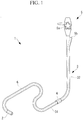
Fig. 1} Fig. 1 is an external view of a guiding device according to an embodiment of the present invention. - {
Fig. 2} Fig. 2 is a vertical sectional view illustrating the internal structure of the guiding device inFig. 1 . - {
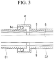
Fig. 3} Fig. 3 is a vertical sectional view illustrating a modification of a rotating section of the guiding device inFig. 1 . - {
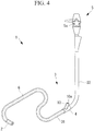
Fig. 4} Fig. 4 is an external view of a modification of the guiding device inFig. 1 . - {
Fig. 5} Fig. 5 is a vertical sectional view illustrating the configuration of a rotation support provided in a branch section inFig. 4 . - {
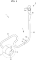
Fig. 6} Fig. 6 is an external view of another modification of the guiding device inFig. 1 . - {
Fig. 7} Fig. 7 is a partial vertical sectional view illustrating another modification of the guiding device inFig. 1 . - {
Fig. 8} Fig. 8 is an external view of another modification of the guiding device inFig. 1 . - {
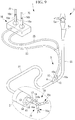
Fig. 9} Fig. 9 is an external view of another modification of the guiding device inFig. 1 . - {
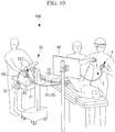
Fig. 10} Fig. 10 illustrates the overall configuration of a surgical system equipped with the guiding device inFig. 9 . - A guiding
device 1 according to an embodiment of the present invention will be described below with reference to the drawings. - As shown in
Figs. 1 and2 , the guidingdevice 1 according to this embodiment includes an elongateflexible section 3 having abending part 2 at the distal end thereof, a rotatingsection 4 provided at an intermediate position of theflexible section 3 in the longitudinal direction thereof, amanipulation unit 5 connected to the proximal end of theflexible section 3, and achannel tube 6 disposed in the longitudinal direction within theflexible section 3. - The
flexible section 3 includesflexible tubes flexible section 3, and, over the entirety thereof, is flexible and bendable in conformity to the shape of the body cavity. Theflexible tubes flexible section 3 in the longitudinal direction and includes afirst part 31 that is located at the distal end and that is to be inserted into the body cavity and asecond part 32 that is located at the proximal end and that is to be disposed outside the body. The lengths of thefirst part 31 and thesecond part 32 can be appropriately selected. For example, if the guidingdevice 1 is to be used for treatment of appendicitis, the length of thefirst part 31 is 1000 mm, and the length of thesecond part 32 is 600 mm. - The
rotating section 4 connects thefirst part 31 and thesecond part 32 to each other in a manner allowing relative rotation thereof about the longitudinal axis of theflexible section 3. In detail, the outer peripheral surface of the proximal end portion of thefirst part 31 is provided with a flange-like protrusion 4a extending in the circumferential direction. The inner peripheral surface of the distal end portion of thesecond part 32 is provided with anannular guide groove 4b extending in the circumferential direction. Therotating section 4 is configured by engaging the distal end portion of thesecond part 32 with the outer side of the proximal end portion of thefirst part 31 such that theprotrusion 4a fits into theguide groove 4b. - Alternatively, as shown in
Fig. 3 , therotating section 4 may be provided with a rollingbearing 4c that is disposed in an annular gap between the outer peripheral surface of the proximal end portion of thefirst part 31 and the inner peripheral surface of the distal end portion of thesecond part 32 and that supports the proximal end portion of thefirst part 31 and the distal end portion of thesecond part 32 in a manner allowing relative rotation thereof. - Furthermore, the connection area between the
first part 31 and thesecond part 32 may be provided with a waterproof seal (not shown) for preventing water from entering the guidingdevice 1 through the gap between thefirst part 31 and thesecond part 32 when, for example, cleaning the guidingdevice 1. - The
manipulation unit 5 includes anangle knob 5a to be used by an operator for manually controlling the bending direction and the bending angle of the bendingpart 2.Reference sign 7 denotes a pulley that rotates together with theangle knob 5a, andreference sign 8 denotes a manipulation wire that connects thepulley 7 and the distal end of theflexible section 3. The outer peripheral surface of themanipulation wire 8 is covered with asheath 9. When theangle knob 5a rotates, thepulley 7 rotates so as to push and pull themanipulation wire 8, thereby bending the bendingpart 2. - The
channel tube 6 has an inner diameter that allows a medical device, such as an endoscope or a treatment tool, to be inserted therein, and has openings at both ends thereof. The distal end of thechannel tube 6 is fixed to the distal end surface of theflexible section 3. The proximal end of thechannel tube 6 is disposed at aninsertion port 5b provided in themanipulation unit 5. Thechannel tube 6 has higher flexibility than theflexible tubes flexible section 3 and is deformable in conformity to bending and twisting of theflexible section 3 and the bendingpart 2. - Next, the operation of the guiding
device 1 having the above-described configuration will be described. - The guiding
device 1 according to this embodiment is used in surgery that involves the use of an endoscope or a treatment tool. For example, thefirst part 31 of theflexible section 3 is inserted into the large intestine through the anus of a patient so that the distal end of theflexible section 3 is disposed in a target area within the large intestine. Then, an endoscope is inserted into thechannel tube 6 through theinsertion port 5b of themanipulation unit 5 so that the endoscope protrudes from an opening in the distal end surface of theflexible section 3. Thus, the interior of the large intestine can be observed with the endoscope. - The operator rotates the
angle knob 5a of themanipulation unit 5 held with his/her left hand so as to bend the bendingpart 2. This causes the distal end of the endoscope to be oriented toward the inner wall of the large intestine, so that the inner wall can be observed. Moreover, with the bendingpart 2 in the bent state, the operator holds a section of thefirst part 31 exposed outside the body by the operator's right hand and twists this section about the longitudinal axis so as to rotate the distal end of theflexible section 3. This causes the distal end of the endoscope to move in the circumferential direction along the inner wall of the large intestine, so that the observation range of the inner wall can be moved in the circumferential direction. - When twisting the
flexible section 3, the operator feels a resistance force caused by torsional rigidity of theflexible section 3. This resistance force increases with an increasing amount of torsion of theflexible section 3. Among the components constituting theflexible section 3, the torsional rigidities of theflexible tubes first part 31 and thesecond part 32 are connected to each other in a manner allowing relative rotation thereof by therotating section 4 so that even when thefirst part 31 is twisted, the torsion is not transmitted to thesecond part 32 or themanipulation unit 5. Specifically, the section that generates a resistance force against a twisting operation performed by a surgeon is mainly thefirst part 31. Furthermore, since torsional deformation occurring in thefirst part 31 is cancelled out by the rotation of the distal end and the proximal end thereof, the amount of torsion and the resistance force do not increase. This is advantageous in that the operator can easily rotate the distal end of theflexible section 3 by simply applying a small torque by performing a small twisting movement with his/her right hand. - In this embodiment, the opening at the proximal end of the
channel tube 6 is disposed at theinsertion port 5b of themanipulation unit 5. Alternatively, as shown inFig. 4 , the distal end portion of thesecond part 32 may be provided with abranch section 10, and the opening at the proximal end of thechannel tube 6 may be disposed at aninsertion port 10a provided in thebranch section 10. Thebranch section 10 extends in a direction intersecting the longitudinal axis of thesecond part 32 and has theinsertion port 10a at the distal end thereof. - Accordingly, this allows for improved user-friendliness in a case where the guiding
device 1 and the medical device are to be operated by different operators. - Furthermore, in this embodiment, a rotation support that supports the proximal end of the
channel tube 6 in a rotatable manner about the longitudinal axis of thechannel tube 6 may be provided. - For example, as shown in
Fig. 5 , in the configuration equipped with thebranch section 10, thebranch section 10 may be provided with arotation support 11. Therotation support 11 is constituted of, for example, a rolling bearing that supports the outer peripheral surface of the proximal end portion of thechannel tube 6. Thebranch section 10 may be provided with a waterproof seal (not shown) for preventing water from entering from the periphery of thechannel tube 6. - Although the
channel tube 6 also becomes twisted when thefirst part 31 is twisted, this torsion of thechannel tube 6 is quickly canceled out by rotation of the proximal end portion thereof supported by therotation support 11. Therefore, thechannel tube 6 can be prevented from being twisted by a large amount, thus preventing thechannel tube 6 from being crushed at an intermediate position thereof. Furthermore, since the torsion of thechannel tube 6 is reduced, a resistance force against the twisting operation performed on theflexible section 3 can be further reduced. - As shown in
Fig. 6 , thebranch section 10 may have theinsertion port 10a on the extension of the longitudinal axis of thefirst part 31 with respect to the proximal end of thefirst part 31, that is, at a position opposed to thefirst part 31 in the direction of the longitudinal axis thereof, such that thechannel tube 6 extends straight from the proximal end of thefirst part 31 to theinsertion port 10a. In this case, thesecond part 31 is connected to thefirst part 31 at a certain angle instead of being connected straight thereto. - In a bent area of the
channel tube 6, friction tends to occur due to contact between the inner wall of thechannel tube 6 and the medical device. This friction leads to reduced ease of operation of the medical device. By providing theinsertion port 10a at a position that allows the proximal end portion of thechannel tube 6 to be disposed straight, the friction occurring between thechannel tube 6 and the medical device can be reduced, thereby allowing for improved ease of operation of the medical device. - Furthermore, as shown in
Fig. 7 , in this embodiment, atube holder 12 that maintains thechannel tube 6 at a position coaxial with theflexible section 3 is preferably provided within theflexible section 3. Thetube holder 12 is, for example, a disk-shaped member disposed in the radial direction within theflexible section 3. This disk-shaped member has its outer peripheral surface fixed to the inner peripheral surface of theflexible tubes channel tube 6 extends. A plurality oftube holders 12 may be provided at a plurality of positions in the longitudinal direction of theflexible section 3. - In a case where the longitudinal axis of the
channel tube 6 is decentered from the longitudinal axis of theflexible section 3, thechannel tube 6 may possibly rotate about the longitudinal axis of theflexible section 3 and interfere with surrounding components. In contrast, in the case where the longitudinal axis of thechannel tube 6 is aligned with the longitudinal axis of theflexible section 3, thechannel tube 6 rotates about the longitudinal axis at a fixed position relative to theflexible section 3. Therefore, thechannel tube 6 can be prevented from interfering with surrounding components. - Furthermore, although a single-lumen-
type guiding device 1 equipped with asingle channel tube 6 is described in this embodiment, the guidingdevice 1 may be of a multi-lumen-type that has a plurality ofchannel tubes Fig. 8 . For example, the guidingdevice 1 may have a singleendoscope channel tube 61 and two treatment-tool channel tubes channel tubes manipulation unit 5 and thebranch section 10. - The overall torsional rigidity of the
flexible section 3 increases with an increasing number of components contained in theflexible section 3. According to this embodiment, even with the distal end of theflexible section 3 having such large torsional rigidity, the distal end of theflexible section 3 can be rotated with only a small movement and a small force. - Furthermore, as shown in
Fig. 9 , in this embodiment, the guidingdevice 1 may include a pair of left andright arms 14 each having a manually-operable or electrically-operablearm bending part 13.Reference sign 16 denotes an arm manipulation unit to be operated for bending thearm bending parts 13. Thearm manipulation unit 16 is provided withmanipulation members 16a, such as levers or joysticks. When themanipulation members 16a are operated by the operator, thearm bending parts 13 are bent and driven in accordance with the operation. - The
arms 14 protrude from the distal end surface of theflexible section 3 and individually havearm channels 14a that communicate with the treatment-tool channel tubes. Thearm channels 14a respectively communicate withinsertion ports 16b provided in themanipulation members 16a viachannel tubes 25 extending from thebranch section 10. By changing the bending direction of thearm bending parts 13 by operating themanipulation members 16a in a state where, for example,treatment tools 70 are inserted in thearm channels 14a through theinsertion ports 16, the orientation of, for example, thetreatment tools 70 protruding from thearm channels 14a can be changed. - The distal end surface of the guiding
device 1 is provided with achannel tube 64 that communicates with theinsertion port 5b, so that an auxiliary treatment tool can be inserted into the body from theinsertion port 5b via thechannel tube 64. Furthermore, thechannel tube 61 communicates with theinsertion port 10a so that an endoscope, for example, can be inserted into the body from theinsertion port 10a via thechannel tube 61. - The guiding
device 1 inFig. 9 can be applied to asurgical system 100 shown inFig. 10 . - The
surgical system 100 includes the guidingdevice 1, amanipulation input device 20 to be operated by an operator, adrive controller 30 that electrically drives thearm bending parts 13 and thetreatment tools 70 within the treatment-tool channel tubes of the guidingdevice 1 in accordance with an operation input to themanipulation input device 20, and adisplay unit 40 that displays an endoscope image acquired by the endoscope within the endoscope channel tube. - In this
guiding device 1, the proximal ends of the two treatment-tool channel tubes are disposed at theinsertion port 10a of thebranch section 10. The proximal ends ofchannel tubes 15 extending outward from theinsertion port 10a are connected tomanipulation members 23, such as levers or joysticks. - The
manipulation input device 20 includes a manipulation table 21 set beside a bed on which a patient lies and themanipulation members 23 fixed on the manipulation table 21. Themanipulation input device 20 hasmanipulation units 22 that are inserted through insertion ports (not shown) of themanipulation members 23 and that are attached toflexible sections 70b of thetreatment tools 70 having distal-end joints 70a, and transmit an input signal corresponding to an operation input from themanipulation units 22 to thedrive controller 30. - The
drive controller 30 actuates the distal-end joints 70a of thetreatment tools 70 in accordance with the input signal from themanipulation input device 20. - The
manipulation members 23 and thechannel tubes 15 shown inFig. 10 respectively correspond to themanipulation members 16a and thechannel tubes 25 shown inFig. 9 . Specifically, the configuration shown inFig. 10 is obtained by detaching themanipulation members 16a shown inFig. 9 from the base and installing them in the manipulation table 20. - Assuming that the
flexible section 3 of the guidingdevice 1 is not provided with therotating section 4, the entireflexible section 3 would have to be twisted by a large amount to rotate the distal end of theflexible section 3. In this case, since the proximal ends of thetreatment tools 70 extending from thebranch section 10 are connected to thedrive controller 30 fixed to the manipulation table 21, a large torsion would also occur in thechannel tubes 15 and thetreatment tools 70 within thechannel tubes 15, causing the sections of thechannel tubes 15 and thetreatment tools 70 located outside the body (i.e., external sections) to move by a large distance or to bend with excessive curvature. If the movement or bending of the external sections poses a problem for electrically operating thetreatment tools 70, the operator would have to temporarily suspend the operation of themanipulation input device 20 to correct the positions and shapes of the external sections of thechannel tubes 15 and thetreatment tools 70. - In contrast, in this embodiment, the
flexible sections 3 are provided with therotating sections 4 so that only a slight torsion occurs in thetreatment tools 70. Thus, the external sections of thechannel tubes 15 and thetreatment tools 70 remain substantially still without being affected by the twisting operation of theflexible sections 3. Accordingly, this is advantageous in that the operator can concentrate on using themanipulation units 22 to electrically operate thetreatment tools 70. -
- 1
- guiding device
- 2
- bending part
- 3
- flexible section
- 4
- rotating section
- 4a
- protrusion
- 4b
- guide groove
- 4c
- rolling bearing
- 5
- manipulation unit
- 5a
- angle knob
- 5b
- insertion port
- 6
- channel tube
- 7
- pulley
- 8
- manipulation wire
- 9
- sheath
- 10
- branch section
- 10a
- insertion port
- 11
- rotation support
- 12
- tube holder
- 13
- arm bending part
- 14
- arm
- 14a
- arm channel
- 15
- channel tube
- 16
- arm manipulation unit
- 20
- manipulation input device
- 21
- manipulation table
- 22
- manipulation unit
- 30
- drive controller
- 31
- first part
- 32
- second part
- 40
- display unit
- 100
- surgical system
Claims (8)
- A guiding device comprising:an elongate flexible section having flexibility and provided with a bending part, which is bendable, at a distal end thereof;a channel tube having flexibility and disposed in a longitudinal direction within the flexible section;a manipulation unit that is provided at a proximal end of the flexible section and that is to be manually operated for bending the bending part; anda rotating section provided at an intermediate position of the flexible section in the longitudinal direction,wherein the flexible section has a first part at the distal end and a second part at the proximal end, andwherein the rotating section connects the first part to the second part in a rotatable manner about a longitudinal axis of the flexible section.
- The guiding device according to Claim 1, further comprising:a rotation support that supports a proximal end of the channel tube in a rotatable manner about a longitudinal axis of the channel tube.
- The guiding device according to Claim 1 or 2, further comprising:a tube holder that is provided within the flexible section and that maintains the channel tube at a position coaxial with the flexible section.
- The guiding device according to any one of Claims 1 to 3, further comprising:a plurality of the channel tubes that are arranged parallel to each other.
- The guiding device according to any one of Claims 1 to 4, further comprising:a branch section that is provided at the second part, extends in a direction intersecting a longitudinal axis of the second part, and has an insertion port through which a medical device is insertable,wherein a proximal end of the channel tube is disposed at the insertion port of the branch section.
- The guiding device according to Claim 5,
wherein the branch section has the insertion port on an extension of a longitudinal axis of the first part, and
wherein a proximal end portion of the channel tube is disposed at the branch section in line with the extension of the longitudinal axis of the first part. - The guiding device according to any one of Claims 1 to 6, further comprising:an arm that protrudes from the distal end of the flexible section and that has an arm bending part, which is bendable, and an arm channel communicating with the channel tube; andan arm manipulation unit to be operated for bending the arm bending part.
- A surgical system comprising:the guiding device according to any one of Claims 1 to 7;a treatment tool insertable into the channel tube of the guiding device;a manipulation input device to be operated by an operator; anda drive controller that electrically drives the treatment tool within the channel tube in accordance with an operation input to the manipulation input device.
Applications Claiming Priority (2)
| Application Number | Priority Date | Filing Date | Title |
|---|---|---|---|
| JP2014123868A JP6203132B2 (en) | 2014-06-17 | 2014-06-17 | Guide device and surgical system |
| PCT/JP2015/062880 WO2015194263A1 (en) | 2014-06-17 | 2015-04-28 | Guide apparatus and surgery system |
Publications (3)
| Publication Number | Publication Date |
|---|---|
| EP3158909A1 true EP3158909A1 (en) | 2017-04-26 |
| EP3158909A4 EP3158909A4 (en) | 2018-02-14 |
| EP3158909B1 EP3158909B1 (en) | 2019-02-13 |
Family
ID=54935258
Family Applications (1)
| Application Number | Title | Priority Date | Filing Date |
|---|---|---|---|
| EP15809885.5A Not-in-force EP3158909B1 (en) | 2014-06-17 | 2015-04-28 | Guiding device and surgical system |
Country Status (5)
| Country | Link |
|---|---|
| US (1) | US20170071458A1 (en) |
| EP (1) | EP3158909B1 (en) |
| JP (1) | JP6203132B2 (en) |
| CN (1) | CN106455914B (en) |
| WO (1) | WO2015194263A1 (en) |
Families Citing this family (5)
| Publication number | Priority date | Publication date | Assignee | Title |
|---|---|---|---|---|
| US20170215696A1 (en) * | 2016-01-29 | 2017-08-03 | Boston Scientific Scimed, Inc. | Endoscopy systems and related methods |
| CN110769990B (en) * | 2017-06-21 | 2022-11-01 | 奥林巴斯株式会社 | Manipulator and its joint structure |
| KR102414011B1 (en) | 2017-12-29 | 2022-06-27 | 더 보드 오브 리젠츠 오브 더 유니버시티 오브 텍사스 시스템 | A surgical instrument and a method of positioning an end effector with respect to a cap on the end of a sheath |
| WO2020092097A1 (en) * | 2018-10-31 | 2020-05-07 | Canon U.S.A., Inc. | Medical apparatus with reflow trapped anchors and method of use thereof |
| JPWO2021255877A1 (en) * | 2020-06-17 | 2021-12-23 |
Family Cites Families (13)
| Publication number | Priority date | Publication date | Assignee | Title |
|---|---|---|---|---|
| JPS5668426A (en) * | 1979-11-12 | 1981-06-09 | Olympus Optical Co | Endoscope |
| JPH02206417A (en) * | 1989-02-03 | 1990-08-16 | Olympus Optical Co Ltd | Flexible tube for insertion in body cavity |
| US6610007B2 (en) * | 2000-04-03 | 2003-08-26 | Neoguide Systems, Inc. | Steerable segmented endoscope and method of insertion |
| JP2002325718A (en) * | 2001-05-02 | 2002-11-12 | Asahi Optical Co Ltd | Endoscope |
| JP4445736B2 (en) * | 2003-10-01 | 2010-04-07 | オリンパス株式会社 | Insertion aid for treatment of full-thickness colorectal resection and its medical instrument system |
| DE102004058929A1 (en) * | 2004-12-07 | 2006-06-08 | Stm Medizintechnik Starnberg Gmbh | Endoscope with rotatable distal endoscope head e.g. for endoscope, has head which is connected by bendable end piece with endoscope shank to tubular construction unit |
| JP5121132B2 (en) * | 2005-11-02 | 2013-01-16 | オリンパスメディカルシステムズ株式会社 | Endoscope system and operation assist device for endoscope |
| US9962066B2 (en) * | 2005-12-30 | 2018-05-08 | Intuitive Surgical Operations, Inc. | Methods and apparatus to shape flexible entry guides for minimally invasive surgery |
| JP5407036B2 (en) * | 2008-09-02 | 2014-02-05 | オリンパスメディカルシステムズ株式会社 | Treatment endoscope |
| JP5179413B2 (en) * | 2009-03-09 | 2013-04-10 | Hoya株式会社 | Endoscope guide tube device |
| JP5052553B2 (en) * | 2009-03-19 | 2012-10-17 | オリンパス株式会社 | Treatment endoscope |
| JP5144712B2 (en) * | 2010-05-11 | 2013-02-13 | オリンパスメディカルシステムズ株式会社 | Endoscope |
| WO2012164978A1 (en) * | 2011-06-01 | 2012-12-06 | オリンパスメディカルシステムズ株式会社 | Endoscope |
-
2014
- 2014-06-17 JP JP2014123868A patent/JP6203132B2/en active Active
-
2015
- 2015-04-28 WO PCT/JP2015/062880 patent/WO2015194263A1/en not_active Ceased
- 2015-04-28 CN CN201580022743.1A patent/CN106455914B/en active Active
- 2015-04-28 EP EP15809885.5A patent/EP3158909B1/en not_active Not-in-force
-
2016
- 2016-11-28 US US15/361,881 patent/US20170071458A1/en not_active Abandoned
Also Published As
| Publication number | Publication date |
|---|---|
| JP2016002226A (en) | 2016-01-12 |
| CN106455914A (en) | 2017-02-22 |
| WO2015194263A1 (en) | 2015-12-23 |
| JP6203132B2 (en) | 2017-09-27 |
| EP3158909B1 (en) | 2019-02-13 |
| US20170071458A1 (en) | 2017-03-16 |
| EP3158909A4 (en) | 2018-02-14 |
| CN106455914B (en) | 2018-06-29 |
Similar Documents
| Publication | Publication Date | Title |
|---|---|---|
| EP3321047A1 (en) | Surgical robot | |
| EP3320873A1 (en) | Surgical robot | |
| EP3158909B1 (en) | Guiding device and surgical system | |
| EP1757217B1 (en) | Endoscope and curve control assist member for endoscope | |
| CN106231983B (en) | Treatment apparatus adapter, endoscope and endoscopic system | |
| EP3025674B1 (en) | Therapeutic manipulator and manipulator system | |
| US20170020370A1 (en) | Transmission mechanism, raising device, and inserting apparatus | |
| EP3537946B1 (en) | A device for use in hysteroscopy | |
| JP6153678B2 (en) | Manipulator and manipulator system | |
| US20190099062A1 (en) | Medical device | |
| EP3158911A1 (en) | Endoscope device | |
| US20140296771A1 (en) | Insertion body, insertion apparatus, rotation unit and rotative force transmission unit | |
| US20170007346A1 (en) | Treatment device and surgical system | |
| US20170049523A1 (en) | Treatment instrument adaptor and surgical manipulator system | |
| CN105208910B (en) | Medical device | |
| US11369447B2 (en) | Surgical system and support device | |
| KR100881811B1 (en) | Endoscope, endoscope bending operation aid and one set of bending operation knob | |
| EP4169563A1 (en) | Long medical device | |
| EP3219246A1 (en) | Dialing unit and introduction device | |
| US20230225597A1 (en) | Endoscopic imaging device and endoscope | |
| US20210259529A1 (en) | Guide tube, treatment system and guide-tube attachment method |
Legal Events
| Date | Code | Title | Description |
|---|---|---|---|
| STAA | Information on the status of an ep patent application or granted ep patent |
Free format text: STATUS: THE INTERNATIONAL PUBLICATION HAS BEEN MADE |
|
| PUAI | Public reference made under article 153(3) epc to a published international application that has entered the european phase |
Free format text: ORIGINAL CODE: 0009012 |
|
| STAA | Information on the status of an ep patent application or granted ep patent |
Free format text: STATUS: REQUEST FOR EXAMINATION WAS MADE |
|
| 17P | Request for examination filed |
Effective date: 20170103 |
|
| AK | Designated contracting states |
Kind code of ref document: A1 Designated state(s): AL AT BE BG CH CY CZ DE DK EE ES FI FR GB GR HR HU IE IS IT LI LT LU LV MC MK MT NL NO PL PT RO RS SE SI SK SM TR |
|
| AX | Request for extension of the european patent |
Extension state: BA ME |
|
| DAV | Request for validation of the european patent (deleted) | ||
| DAX | Request for extension of the european patent (deleted) | ||
| A4 | Supplementary search report drawn up and despatched |
Effective date: 20180117 |
|
| RIC1 | Information provided on ipc code assigned before grant |
Ipc: A61B 1/00 20060101AFI20180111BHEP |
|
| GRAP | Despatch of communication of intention to grant a patent |
Free format text: ORIGINAL CODE: EPIDOSNIGR1 |
|
| STAA | Information on the status of an ep patent application or granted ep patent |
Free format text: STATUS: GRANT OF PATENT IS INTENDED |
|
| INTG | Intention to grant announced |
Effective date: 20180809 |
|
| RIN1 | Information on inventor provided before grant (corrected) |
Inventor name: KISHI, KOSUKE Inventor name: OGAWA, RYOHEI Inventor name: YANAGIHARA, MASARU |
|
| GRAJ | Information related to disapproval of communication of intention to grant by the applicant or resumption of examination proceedings by the epo deleted |
Free format text: ORIGINAL CODE: EPIDOSDIGR1 |
|
| STAA | Information on the status of an ep patent application or granted ep patent |
Free format text: STATUS: REQUEST FOR EXAMINATION WAS MADE |
|
| GRAS | Grant fee paid |
Free format text: ORIGINAL CODE: EPIDOSNIGR3 |
|
| STAA | Information on the status of an ep patent application or granted ep patent |
Free format text: STATUS: GRANT OF PATENT IS INTENDED |
|
| GRAP | Despatch of communication of intention to grant a patent |
Free format text: ORIGINAL CODE: EPIDOSNIGR1 |
|
| INTC | Intention to grant announced (deleted) | ||
| GRAA | (expected) grant |
Free format text: ORIGINAL CODE: 0009210 |
|
| STAA | Information on the status of an ep patent application or granted ep patent |
Free format text: STATUS: THE PATENT HAS BEEN GRANTED |
|
| INTG | Intention to grant announced |
Effective date: 20181221 |
|
| AK | Designated contracting states |
Kind code of ref document: B1 Designated state(s): AL AT BE BG CH CY CZ DE DK EE ES FI FR GB GR HR HU IE IS IT LI LT LU LV MC MK MT NL NO PL PT RO RS SE SI SK SM TR |
|
| REG | Reference to a national code |
Ref country code: GB Ref legal event code: FG4D |
|
| REG | Reference to a national code |
Ref country code: CH Ref legal event code: EP Ref country code: AT Ref legal event code: REF Ref document number: 1095740 Country of ref document: AT Kind code of ref document: T Effective date: 20190215 |
|
| REG | Reference to a national code |
Ref country code: IE Ref legal event code: FG4D |
|
| REG | Reference to a national code |
Ref country code: DE Ref legal event code: R096 Ref document number: 602015024663 Country of ref document: DE |
|
| REG | Reference to a national code |
Ref country code: LT Ref legal event code: MG4D |
|
| REG | Reference to a national code |
Ref country code: NL Ref legal event code: MP Effective date: 20190213 |
|
| PG25 | Lapsed in a contracting state [announced via postgrant information from national office to epo] |
Ref country code: NO Free format text: LAPSE BECAUSE OF FAILURE TO SUBMIT A TRANSLATION OF THE DESCRIPTION OR TO PAY THE FEE WITHIN THE PRESCRIBED TIME-LIMIT Effective date: 20190513 Ref country code: SE Free format text: LAPSE BECAUSE OF FAILURE TO SUBMIT A TRANSLATION OF THE DESCRIPTION OR TO PAY THE FEE WITHIN THE PRESCRIBED TIME-LIMIT Effective date: 20190213 Ref country code: FI Free format text: LAPSE BECAUSE OF FAILURE TO SUBMIT A TRANSLATION OF THE DESCRIPTION OR TO PAY THE FEE WITHIN THE PRESCRIBED TIME-LIMIT Effective date: 20190213 Ref country code: PT Free format text: LAPSE BECAUSE OF FAILURE TO SUBMIT A TRANSLATION OF THE DESCRIPTION OR TO PAY THE FEE WITHIN THE PRESCRIBED TIME-LIMIT Effective date: 20190613 Ref country code: NL Free format text: LAPSE BECAUSE OF FAILURE TO SUBMIT A TRANSLATION OF THE DESCRIPTION OR TO PAY THE FEE WITHIN THE PRESCRIBED TIME-LIMIT Effective date: 20190213 Ref country code: LT Free format text: LAPSE BECAUSE OF FAILURE TO SUBMIT A TRANSLATION OF THE DESCRIPTION OR TO PAY THE FEE WITHIN THE PRESCRIBED TIME-LIMIT Effective date: 20190213 |
|
| PGFP | Annual fee paid to national office [announced via postgrant information from national office to epo] |
Ref country code: DE Payment date: 20190425 Year of fee payment: 5 |
|
| PG25 | Lapsed in a contracting state [announced via postgrant information from national office to epo] |
Ref country code: HR Free format text: LAPSE BECAUSE OF FAILURE TO SUBMIT A TRANSLATION OF THE DESCRIPTION OR TO PAY THE FEE WITHIN THE PRESCRIBED TIME-LIMIT Effective date: 20190213 Ref country code: GR Free format text: LAPSE BECAUSE OF FAILURE TO SUBMIT A TRANSLATION OF THE DESCRIPTION OR TO PAY THE FEE WITHIN THE PRESCRIBED TIME-LIMIT Effective date: 20190514 Ref country code: IS Free format text: LAPSE BECAUSE OF FAILURE TO SUBMIT A TRANSLATION OF THE DESCRIPTION OR TO PAY THE FEE WITHIN THE PRESCRIBED TIME-LIMIT Effective date: 20190613 Ref country code: LV Free format text: LAPSE BECAUSE OF FAILURE TO SUBMIT A TRANSLATION OF THE DESCRIPTION OR TO PAY THE FEE WITHIN THE PRESCRIBED TIME-LIMIT Effective date: 20190213 Ref country code: BG Free format text: LAPSE BECAUSE OF FAILURE TO SUBMIT A TRANSLATION OF THE DESCRIPTION OR TO PAY THE FEE WITHIN THE PRESCRIBED TIME-LIMIT Effective date: 20190513 Ref country code: RS Free format text: LAPSE BECAUSE OF FAILURE TO SUBMIT A TRANSLATION OF THE DESCRIPTION OR TO PAY THE FEE WITHIN THE PRESCRIBED TIME-LIMIT Effective date: 20190213 |
|
| REG | Reference to a national code |
Ref country code: AT Ref legal event code: MK05 Ref document number: 1095740 Country of ref document: AT Kind code of ref document: T Effective date: 20190213 |
|
| PG25 | Lapsed in a contracting state [announced via postgrant information from national office to epo] |
Ref country code: AL Free format text: LAPSE BECAUSE OF FAILURE TO SUBMIT A TRANSLATION OF THE DESCRIPTION OR TO PAY THE FEE WITHIN THE PRESCRIBED TIME-LIMIT Effective date: 20190213 Ref country code: ES Free format text: LAPSE BECAUSE OF FAILURE TO SUBMIT A TRANSLATION OF THE DESCRIPTION OR TO PAY THE FEE WITHIN THE PRESCRIBED TIME-LIMIT Effective date: 20190213 Ref country code: DK Free format text: LAPSE BECAUSE OF FAILURE TO SUBMIT A TRANSLATION OF THE DESCRIPTION OR TO PAY THE FEE WITHIN THE PRESCRIBED TIME-LIMIT Effective date: 20190213 Ref country code: IT Free format text: LAPSE BECAUSE OF FAILURE TO SUBMIT A TRANSLATION OF THE DESCRIPTION OR TO PAY THE FEE WITHIN THE PRESCRIBED TIME-LIMIT Effective date: 20190213 Ref country code: EE Free format text: LAPSE BECAUSE OF FAILURE TO SUBMIT A TRANSLATION OF THE DESCRIPTION OR TO PAY THE FEE WITHIN THE PRESCRIBED TIME-LIMIT Effective date: 20190213 Ref country code: SK Free format text: LAPSE BECAUSE OF FAILURE TO SUBMIT A TRANSLATION OF THE DESCRIPTION OR TO PAY THE FEE WITHIN THE PRESCRIBED TIME-LIMIT Effective date: 20190213 Ref country code: RO Free format text: LAPSE BECAUSE OF FAILURE TO SUBMIT A TRANSLATION OF THE DESCRIPTION OR TO PAY THE FEE WITHIN THE PRESCRIBED TIME-LIMIT Effective date: 20190213 Ref country code: CZ Free format text: LAPSE BECAUSE OF FAILURE TO SUBMIT A TRANSLATION OF THE DESCRIPTION OR TO PAY THE FEE WITHIN THE PRESCRIBED TIME-LIMIT Effective date: 20190213 |
|
| REG | Reference to a national code |
Ref country code: DE Ref legal event code: R097 Ref document number: 602015024663 Country of ref document: DE |
|
| PG25 | Lapsed in a contracting state [announced via postgrant information from national office to epo] |
Ref country code: SM Free format text: LAPSE BECAUSE OF FAILURE TO SUBMIT A TRANSLATION OF THE DESCRIPTION OR TO PAY THE FEE WITHIN THE PRESCRIBED TIME-LIMIT Effective date: 20190213 Ref country code: PL Free format text: LAPSE BECAUSE OF FAILURE TO SUBMIT A TRANSLATION OF THE DESCRIPTION OR TO PAY THE FEE WITHIN THE PRESCRIBED TIME-LIMIT Effective date: 20190213 |
|
| REG | Reference to a national code |
Ref country code: CH Ref legal event code: PL |
|
| REG | Reference to a national code |
Ref country code: BE Ref legal event code: MM Effective date: 20190430 |
|
| PLBE | No opposition filed within time limit |
Free format text: ORIGINAL CODE: 0009261 |
|
| STAA | Information on the status of an ep patent application or granted ep patent |
Free format text: STATUS: NO OPPOSITION FILED WITHIN TIME LIMIT |
|
| PG25 | Lapsed in a contracting state [announced via postgrant information from national office to epo] |
Ref country code: AT Free format text: LAPSE BECAUSE OF FAILURE TO SUBMIT A TRANSLATION OF THE DESCRIPTION OR TO PAY THE FEE WITHIN THE PRESCRIBED TIME-LIMIT Effective date: 20190213 Ref country code: LU Free format text: LAPSE BECAUSE OF NON-PAYMENT OF DUE FEES Effective date: 20190428 Ref country code: MC Free format text: LAPSE BECAUSE OF FAILURE TO SUBMIT A TRANSLATION OF THE DESCRIPTION OR TO PAY THE FEE WITHIN THE PRESCRIBED TIME-LIMIT Effective date: 20190213 |
|
| 26N | No opposition filed |
Effective date: 20191114 |
|
| GBPC | Gb: european patent ceased through non-payment of renewal fee |
Effective date: 20190513 |
|
| PG25 | Lapsed in a contracting state [announced via postgrant information from national office to epo] |
Ref country code: CH Free format text: LAPSE BECAUSE OF NON-PAYMENT OF DUE FEES Effective date: 20190430 Ref country code: LI Free format text: LAPSE BECAUSE OF NON-PAYMENT OF DUE FEES Effective date: 20190430 |
|
| PG25 | Lapsed in a contracting state [announced via postgrant information from national office to epo] |
Ref country code: BE Free format text: LAPSE BECAUSE OF NON-PAYMENT OF DUE FEES Effective date: 20190430 Ref country code: FR Free format text: LAPSE BECAUSE OF NON-PAYMENT OF DUE FEES Effective date: 20190430 Ref country code: SI Free format text: LAPSE BECAUSE OF FAILURE TO SUBMIT A TRANSLATION OF THE DESCRIPTION OR TO PAY THE FEE WITHIN THE PRESCRIBED TIME-LIMIT Effective date: 20190213 |
|
| PG25 | Lapsed in a contracting state [announced via postgrant information from national office to epo] |
Ref country code: TR Free format text: LAPSE BECAUSE OF FAILURE TO SUBMIT A TRANSLATION OF THE DESCRIPTION OR TO PAY THE FEE WITHIN THE PRESCRIBED TIME-LIMIT Effective date: 20190213 |
|
| PG25 | Lapsed in a contracting state [announced via postgrant information from national office to epo] |
Ref country code: GB Free format text: LAPSE BECAUSE OF NON-PAYMENT OF DUE FEES Effective date: 20190513 Ref country code: IE Free format text: LAPSE BECAUSE OF NON-PAYMENT OF DUE FEES Effective date: 20190428 |
|
| REG | Reference to a national code |
Ref country code: DE Ref legal event code: R119 Ref document number: 602015024663 Country of ref document: DE |
|
| PG25 | Lapsed in a contracting state [announced via postgrant information from national office to epo] |
Ref country code: DE Free format text: LAPSE BECAUSE OF NON-PAYMENT OF DUE FEES Effective date: 20201103 |
|
| PG25 | Lapsed in a contracting state [announced via postgrant information from national office to epo] |
Ref country code: CY Free format text: LAPSE BECAUSE OF FAILURE TO SUBMIT A TRANSLATION OF THE DESCRIPTION OR TO PAY THE FEE WITHIN THE PRESCRIBED TIME-LIMIT Effective date: 20190213 |
|
| PG25 | Lapsed in a contracting state [announced via postgrant information from national office to epo] |
Ref country code: HU Free format text: LAPSE BECAUSE OF FAILURE TO SUBMIT A TRANSLATION OF THE DESCRIPTION OR TO PAY THE FEE WITHIN THE PRESCRIBED TIME-LIMIT; INVALID AB INITIO Effective date: 20150428 Ref country code: MT Free format text: LAPSE BECAUSE OF FAILURE TO SUBMIT A TRANSLATION OF THE DESCRIPTION OR TO PAY THE FEE WITHIN THE PRESCRIBED TIME-LIMIT Effective date: 20190213 |
|
| PG25 | Lapsed in a contracting state [announced via postgrant information from national office to epo] |
Ref country code: MK Free format text: LAPSE BECAUSE OF FAILURE TO SUBMIT A TRANSLATION OF THE DESCRIPTION OR TO PAY THE FEE WITHIN THE PRESCRIBED TIME-LIMIT Effective date: 20190213 |