EP3158810B1 - Apparatus and method for capability update in wireless communication - Google Patents
Apparatus and method for capability update in wireless communication Download PDFInfo
- Publication number
- EP3158810B1 EP3158810B1 EP15795001.5A EP15795001A EP3158810B1 EP 3158810 B1 EP3158810 B1 EP 3158810B1 EP 15795001 A EP15795001 A EP 15795001A EP 3158810 B1 EP3158810 B1 EP 3158810B1
- Authority
- EP
- European Patent Office
- Prior art keywords
- features
- capability indication
- duplex mode
- capability
- communication
- Prior art date
- Legal status (The legal status is an assumption and is not a legal conclusion. Google has not performed a legal analysis and makes no representation as to the accuracy of the status listed.)
- Active
Links
Images


Classifications
-
- H—ELECTRICITY
- H04—ELECTRIC COMMUNICATION TECHNIQUE
- H04L—TRANSMISSION OF DIGITAL INFORMATION, e.g. TELEGRAPHIC COMMUNICATION
- H04L5/00—Arrangements affording multiple use of the transmission path
- H04L5/14—Two-way operation using the same type of signal, i.e. duplex
- H04L5/16—Half-duplex systems; Simplex/duplex switching; Transmission of break signals non-automatically inverting the direction of transmission
-
- H—ELECTRICITY
- H04—ELECTRIC COMMUNICATION TECHNIQUE
- H04W—WIRELESS COMMUNICATION NETWORKS
- H04W8/00—Network data management
- H04W8/22—Processing or transfer of terminal data, e.g. status or physical capabilities
- H04W8/24—Transfer of terminal data
-
- H—ELECTRICITY
- H04—ELECTRIC COMMUNICATION TECHNIQUE
- H04W—WIRELESS COMMUNICATION NETWORKS
- H04W72/00—Local resource management
- H04W72/50—Allocation or scheduling criteria for wireless resources
- H04W72/51—Allocation or scheduling criteria for wireless resources based on terminal or device properties
-
- H—ELECTRICITY
- H04—ELECTRIC COMMUNICATION TECHNIQUE
- H04W—WIRELESS COMMUNICATION NETWORKS
- H04W88/00—Devices specially adapted for wireless communication networks, e.g. terminals, base stations or access point devices
- H04W88/02—Terminal devices
- H04W88/06—Terminal devices adapted for operation in multiple networks or having at least two operational modes, e.g. multi-mode terminals
Definitions
- the invention relates to methods, to devices and to a computer-readable medium of communicating capability information.
- Wireless communication networks are widely deployed to provide various communication services such as telephony, video, data, messaging, broadcasts, and so on. Such networks, which are usually multiple access networks, support communications for multiple users by sharing the available network resources.
- full duplex operation demands extra complexity than that of half duplex operation, as for example described in WO 2013/077554 A1 , GB 2 499 259 A , or US 2013/051288 A1 .
- a full duplex capable device may not always operate in a full duplex mode. Therefore, it is inefficient to size or configure a device's processing capability to operate in full duplex mode together with all other supported features at the same time.
- the disclosure provides a method of communicating capability information operable at an apparatus.
- the apparatus communicates with another device over a carrier, and transmits a capability indication indicative of the capability of the apparatus to support at least two features based on whether the apparatus is operating in a first duplex mode or a second duplex mode.
- the capability indication is configured to indicate support of a first feature being dependent upon a second feature, among the at least two features.
- Another aspect of the disclosure provides a method of communication operable at an apparatus.
- the apparatus communicates with another device over a carrier, and receives a capability indication from the other device, indicative of the capability of the other device to support at least two features based on whether the other device is operating in a first duplex mode or a second duplex mode.
- the apparatus configures the apparatus to support the at least two features based on the capability indication, wherein the capability indication is configured to indicate support of a first feature being dependent upon a second feature, among the at least two features.
- the apparatus includes means for communicating with the other device over a carrier, and means for transmitting a capability indication indicative of the capability of the apparatus to support at least two features based on whether the apparatus is operating in a first duplex mode or a second duplex mode.
- the capability indication is configured to indicate support of a first feature being dependent upon a second feature, among the at least two features.
- the apparatus includes means for communicating with the other device over a carrier, and means for receiving a capability indication from the other device, indicative of the capability of the other device to support at least two features based on whether the other device is operating in a first duplex mode or a second duplex mode.
- the apparatus further includes means for, in response to the capability indication, configuring the apparatus to support the at least two features based on the capability indication, wherein the capability indication is configured to indicate support of a first feature being dependent upon a second feature, among the at least two features.
- the apparatus includes a communication interface, a memory including code, and at least one processor coupled to the communication interface and the memory.
- the processor when executing the code includes a communication control block configured to utilize the communication interface to communicate with another device over a carrier; and a capability indication block configured to transmit a capability indication indicative of the capability of the apparatus to support at least two features based on whether the apparatus is operating in a first duplex mode or a second duplex mode.
- the capability indication is configured to indicate support of a first feature being dependent upon a second feature, among the at least two features.
- the apparatus includes a communication interface, a memory including code, and at least one processor coupled to the communication interface and the memory.
- the processor when executing the code includes a communication control block configured to utilize the communication interface to communicate with another device over a carrier; a capability indication block configured to receive a capability indication from the other device, indicative of the capability of the other device to support at least two features based on whether the other device is operating in a first duplex mode or a second duplex mode; and a configuration control block, in response to the capability indication, configured to configure the apparatus to support the at least two features based on the capability indication.
- the capability indication is configured to indicate support of a first feature being dependent upon a second feature, among the at least two features.
- wireless communication systems can enable or disable optional features and capabilities in different situations. However, sizing of a communication device's processing power to a worst case scenario could be inefficient if optional features or capabilities are signaled independently.
- Communications systems according to some embodiments of the disclosure can support full duplex and half duplex operation, which may be applied to end devices, user equipment, relay nodes, device-to-device (D2D) nodes, or any network nodes (e.g., base station, eNB, macrocell, picocell, small/femto cell). In some embodiments, these devices can send a capability indication or update based on whether the devices are operating in full duplex or half duplex communication.
- D2D device-to-device
- full duplex operation has a number of characteristics.
- wireless communication devices can transmit and receive information (e.g., voice or data traffic) simultaneously in part of the spectrum.
- information e.g., voice or data traffic
- frequency division full duplex the device may transmit and receive on different frequencies or bands at the same time.
- time-division duplex TDD
- the device In time-division duplex (TDD), the device generally transmits and receives in the same spectrum, frequency, or band at different times.
- a full duplex operation may be achieved using the same frequency for both directions (e.g., transmit and receive).
- a device may utilize transmit and receive frequency bands that are identical or fully overlapping (e.g., frequency 302 of FIG. 3 ), partially overlapping (e.g., frequency bands 302 and 304 of FIG. 3 ), or non-overlapping but undesirably close to each other (e.g., frequency bands 302 and 306 of FIG. 3 ).
- same frequency full duplex refers to a full duplex operation in which the same frequency band is used for communication in both directions (e.g., uplink and downlink directions).
- SF-FD operation also includes bi-directional communication using two frequency bands that are not identical, but are overlapped or substantially close to each other such that it is different from the generally known frequency division full duplex operation that relies on the device's ability to separate the two frequency bands, for example, using filters.
- FIG. 1 is a diagram illustrating an example of a hardware implementation for an apparatus 100 employing a processing system 114 according to some embodiments.
- an element, or any portion of an element, or any combination of elements may be implemented with a processing system 114 that includes one or more processors 104.
- the apparatus 100 may be a user equipment (UE), a base station, a network entity, a relay node, or any device capable of data communications (e.g., wireless communications).
- the apparatus 100 can be used to implement a scheduling entity 202 or a subordinate entity 204, as illustrated in FIG. 2 .
- the apparatus 100 may be used to implement a base station, which can be a scheduling entity 202 or a subordinate entity 204.
- the apparatus 100 may be used to implement a relay node or a network node, which may be a scheduling entity 202 or a subordinate entity 204.
- processors 104 include microprocessors, microcontrollers, digital signal processors (DSPs), field programmable gate arrays (FPGAs), programmable logic devices (PLDs), state machines, gated logic, discrete hardware circuits, and other suitable hardware configured to perform the various functionality described throughout this disclosure, for example, in FIGs. 6-11 . That is, the processor 104, as utilized in an apparatus 100, may be used to implement any one or more of the processes described below.
- the processing system 114 may be implemented with a bus architecture, represented generally by the bus 102.
- the bus 102 may include any number of interconnecting buses and bridges depending on the specific application of the processing system 114 and the overall design constraints.
- the bus 102 links together various circuits or components including one or more processors (represented generally by the processor 104), a memory 105, and computer-readable media (represented generally by the computer-readable medium 106).
- the bus 102 may also link various other circuits such as timing sources, peripherals, voltage regulators, and power management circuits, which are well known in the art, and therefore, will not be described any further.
- a bus interface 108 provides an interface between the bus 102 and a transceiver 110.
- the transceiver 110 (a communication interface) provides a means for communicating with various other apparatus over a transmission medium.
- the transceiver 110 may be configured to support full duplex (FD) and/or half duplex (HD) communication.
- FD full duplex
- HD half duplex
- a user interface 112 e.g., keypad, display, speaker, microphone, joystick, trackpad, touchscreen, camera
- the processor 104 is responsible for managing the bus 102 and general processing, including the execution of software stored on the computer-readable medium 106.
- the software when executed by the processor 104, causes the processing system 114 to perform the various functions described below in FIGs. 2-11 for any particular apparatus.
- the computer-readable medium 106 may also be used for storing data that is manipulated by the processor 104 when executing software.
- the various blocks and circuitries of the apparatus 100 may be implemented in software, firmware, hardware, or a combination of software, firmware, and hardware.
- the software may include a capability update code 120 that can process and update a capability indication 122.
- the software may also include a full duplex/half duplex communication code 124.
- a capability indication block 126 is configured to perform functions related to updating or maintaining the capability indication 122
- a feature support block 128 is configured to control (e.g., enable or disable) one or more features based on the capability indication 122.
- the capability indication 122 may be sent to another device to signal the currently supported or configured features of the apparatus 100.
- Some non-limiting examples of the features may include a maximum number of bits in a data unit processed by the apparatus, a number of carriers aggregated for communication, a communication mode (e.g., full-duplex or half-duplex), a signal modulation scheme, and a category of the apparatus.
- a communication mode e.g., full-duplex or half-duplex
- the full duplex/half duplex communication code 124 when executed, configures a full duplex (FD)/half duplex (HD) control block 130 (e.g., a communication control block) to perform functions related to full duplex and half duplex communications.
- the processor 104 also may include a configuration control block 132 that may be configured to coordinate the operations of the feature support blocks 128, FD/HD control block 130, and capability indication block 126.
- the configuration control block 132 may be utilized to control the various configurations that support different features.
- One or more processors 104 in the processing system may execute software.
- Software shall be construed broadly to mean instructions, instruction sets, code, code segments, program code, programs, subprograms, software modules, applications, software applications, software packages, routines, subroutines, objects, executables, threads of execution, procedures, functions, etc., whether referred to as software, firmware, middleware, microcode, hardware description language, or otherwise.
- the software may reside on a computer-readable medium 106.
- the computer-readable medium 106 may be a non-transitory computer-readable medium.
- a non-transitory computer-readable medium includes, by way of example, a magnetic storage device (e.g., hard disk, floppy disk, magnetic strip), an optical disk (e.g., a compact disc (CD) or a digital versatile disc (DVD)), a smart card, a flash memory device (e.g., a card, a stick, or a key drive), a random access memory (RAM), a read only memory (ROM), a programmable ROM (PROM), an erasable PROM (EPROM), an electrically erasable PROM (EEPROM), a register, a removable disk, and any other suitable medium for storing software and/or instructions that may be accessed and read by a computer.
- a magnetic storage device e.g., hard disk, floppy disk, magnetic strip
- an optical disk e.g., a compact disc (CD) or a digital versatile disc (DVD)
- a smart card e.g., a flash memory device (e.g.
- the computer-readable medium 106 may reside in the processing system 114, external to the processing system 114, or distributed across multiple entities including the processing system 114.
- the computer-readable medium 106 may be embodied in a computer program product.
- a computer program product may include a computer-readable medium in packaging materials.
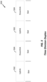
- FIG. 2 is a block diagram illustrating a scheduling entity 202 and a number of subordinate entities 204 engaged in wireless communication utilizing one or more data channels and control channels described in further detail below.
- the scheduling entity 202 and/or the subordinate entities 204 may be implemented using one or more apparatuses 100.
- the channels illustrated in FIG. 2 are not necessarily all of the channels that may be utilized between a scheduling entity 202 and subordinate entities 204, and those of ordinary skill in the art will recognize that other channels may be utilized in addition to those illustrated, such as other control, signaling, and feedback channels.
- the scheduling entity 202 may perform various scheduling functions so that the subordinate entities 204 may communicate with the scheduling entity 202 in an orderly manner. Non-limiting examples of the scheduling functions include determining a scheduling scheme, handling communication resource requests from the subordinate entities, determining data rates for the requesting subordinate entities, and transmitting grants to the subordinate entities.
- the scheduling entity 202 may broadcast data (e.g., uplink or downlink data) to one or more subordinate entities 204 (e.g., secondary or other remote entities). Further, the scheduling entity 202 may send different downlink data to different subordinate entities 204, and the one or more subordinate entities 204 may transmit uplink data to the scheduling entity 202. In addition, the scheduling entity 202 may broadcast a control channel to the subordinate entities 204. The scheduling entity 202 may send different control/signaling data to different subordinate entities 204 through the same control channel or different control channels. The control channel(s) may be used for transmitting signaling, overhead messages, paging messages, or control messages including a capability indication (e.g., capability indication 122 of FIG. 1 ) of the entity. The communication between the scheduling entity 202 and the subordinate entities 204 may be half duplex or full duplex. The scheduling entity 202 may send the capability indication to the subordinate entity 204 or vice versa.
- data e.g., uplink or downlink data
- a scheduling entity 202 may be any suitable radio transceiver apparatus. In some examples, it may be referred to by those skilled in the art as a base station (BS), a base transceiver station (BTS), a radio base station, a radio transceiver, a transceiver function, a basic service set (BSS), an extended service set (ESS), an access point (AP), a Node B, an eNode B (eNB), a mesh node, a relay node, or some other suitable terminology.
- BS basic service set
- ESS extended service set
- AP access point
- Node B an eNode B
- eNB eNode B
- mesh node a relay node, or some other suitable terminology.
- a base station provides wireless access points to a core network for any number of user equipment (UE).
- a wireless communication device may be a scheduling entity 202 and/or a subordinate entity 204.
- Examples of a wireless communication device includes a UE, a cellular phone, a smart phone, a session initiation protocol (SIP) phone, a laptop, a notebook, a netbook, a smartbook, a personal digital assistant (PDA), a satellite radio, a global positioning system (GPS) device, a multimedia device, a video device, a digital audio player (e.g., MP3 player), a camera, entertainment device, wearable communication device, automobile, mesh network, M2M component, a game console, entertainment device, vehicle component, an entity in the Internet of Things, or any other similar functioning device.
- GPS global positioning system
- a wireless communication device may also be referred to by those skilled in the art as a mobile station (MS), a subscriber station, a mobile unit, a subscriber unit, a wireless unit, a remote unit, a mobile device, a wireless device, a remote device, a mobile subscriber station, an access terminal (AT), a mobile terminal, a wireless terminal, a remote terminal, a handset, a terminal, a user agent, a mobile client, a client, or some other suitable terminology.
- MS mobile station
- AT access terminal
- Wireless communication devices for existing wireless communication networks may support optional features that are signaled to the network (e.g., a base station) independent of each other.
- a UE may have capabilities depending on its terminal capability class, category, and/or operational characteristics.
- HSPA High Speed Packet Access
- optional features or capabilities of the device are signaled independent of each other.
- independent signaling of capabilities can lead to inefficient design because the likelihood of a device being configured with the worst case (i.e., all features being enabled) may be low. Therefore, a device design that supports a worst case may generally not be cost effective.
- FIG. 4 is a block diagram illustrating two communication devices 402, 404 communicating to each other using SF-FD in accordance with some embodiments.
- the two devices 402 and 404 may be a scheduling entity 202 and a subordinate entity 204 of FIG. 2 , respectively.
- the communication devices 402 and 404 may be implemented using the apparatus 100 of FIG. 1 .
- Each of the devices 402 and 404 may include a transmitter 406 and a receiver 408, which may be an integrated component or separately component.
- the transmitter 406 of the device 402 may send signals to the receiver of the device 404, while simultaneously the transmitter 406 of the device 404 may send signals to the receiver 408 of the device 402 using the same frequency band or overlapping frequency bands.
- An SF-FD capable device may not always operate in full duplex mode.
- the use of SF-FD operation may depend on the capability of the other end device.
- the use of SF-FD communication may depend on the desired trade-off between spectral efficiency and power consumption.
- the use of SF-FD communication may depend on any interference conditions influencing the amount of transmit path cancellation that may occur as part of the receiver (i.e., the so-called full duplex cancellation level).
- the communication device 402 or 404 may also communicate with another device using time division duplex (TDD) communication, which is a half duplex operation.
- TDD time division duplex
- the communication devices do not transmit and receive signals simultaneously. That is, the communication device transmits and receives at non-lapping time periods.
- the device does not transmit and receive at the same time on the same frequency band or different frequency bands.
- FIG. 5 is a diagram illustrating a TDD communication channel 500 according to some embodiments.
- a TDD communication device may use an uplink channel 502 that is separated from a downlink channel 504 by the allocation of different time slots in the same frequency band or channel 500. Therefore, TDD communication allows asymmetric flow for uplink and downlink data transmission.
- a TDD communication device is allocated different time slots for uplink and downlink transmissions.
- half duplex transmission e.g., TDD
- TDD half duplex transmission
- Rx receiver
- Tx transmitter
- Tx-Rx resource sharing becomes difficult and sometimes not possible. It can result in reduced Rx and/or Tx capability.
- the device may perform at a reduced data rate (e.g., half data rate) during full duplex communication compared to that of half duplex.
- a reduced data rate e.g., half data rate
- Embodiments of the present invention enable and provide for many different types of services or applications, including but not limited to web browsing, video streaming, Voice-Over IP (VoIP), mission critical applications, multi-hop networks, remote operations with real-time feedback (e.g., tele-surgery), etc.
- These different services and applications may be supported using full duplex (e.g., SF-FD) and/or half duplex communication. Therefore, it is beneficial that a wireless communication device can efficiently update, change, or reconfigure its capability or category based on whether full duplex or half duplex communication is enabled.
- a wireless communication device updates or changes its capability or category based on a number of operational characteristics.
- One particular example of such characteristics is whether the device is operating in the full duplex mode (e.g., SF-FD) or half duplex mode.
- a communication device can modify one or more of its operations or capabilities based on whether full duplex or half duplex is used.
- the present disclosure is not limited to using only full duplex/half duplex as a condition for updating or changing a device's capability/category.
- Other suitable operational characteristics may be used to update or change a device's capability/category.
- the communication device may be configured to size its processing power differently for full duplex and half duplex operations.
- the device sends a capability indication to another device to indicate the currently supported features.
- the capability indication is a message having a number of bits less than that of the quantity of the supported features.
- the capability indication has 3 bits that are utilized to signal more than 3 features.
- the capability indication may indicate the support of a first feature in a way that depends on whether or not a second feature is supported or not. In other words, the capability indication is configured such that the support of one or more features is not independently signaled, reported, or updated.
- Some non-limiting examples of the features include a maximum number of bits in a data unit processed by the device, a number of carriers aggregated for communication, a communication mode (e.g., full-duplex or half-duplex), a signal modulation scheme (e.g., quadrature amplitude modulation).
- Table 1 shows the values of a capability indication and two features (A and B) that may be supported by a communication device, which may be any of the devices or apparatuses shown in FIGs. 1 , 2 , 4 , and 6-8 . It should be noted that the feature combinations shown in Table 1 are not exhaustive, and other features combinations may be used.
- the communication device sending the capability indication of Table 1 may be a user equipment or subordinate entity, and the receiving device may be a base station or scheduling entity, or vice versa.
- the receiving device may configure the support of features A and B as illustrated in Tables 2 and 3 as a non-limiting example.
- the capability indication "000” indicates that both features A and B are not supported; therefore, the receiving device is configured to provide no support for features A and B (i.e., configuration "00").
- the capability indication "001" indicates that feature B is supported but not feature A; therefore, the receiving device may be configured to provide no support for both features A and B (i.e., configuration "00") or provide support for feature B but not feature A (i.e., configuration "01”).
- the capability indication “010” indicates that feature A is supported but not feature B; therefore, the receiving device may be configured to provide no support for both features A and B (i.e., configuration "00") or provide support for feature A but not feature B (i.e., configuration "10").
- the receiving device may be configured to provide no support for both features A and B (i.e., configuration "00"), provide support for feature B but not feature A (i.e., configuration "01"), or provide support for feature A but not feature B (i.e., configuration "10”).
- the receiving device may be configured to provide no support for both features A and B (i.e., configuration "00"), provide support for feature B but not feature A (i.e., configuration "01"), provide support for feature A but not feature B (i.e., configuration "10"), or provide support for both features A and B (i.e., configuration "11").
- FIG. 6 is a diagram illustrating a communication device 602 configured as a relay node in accordance with some embodiments.
- the relay node 602 may be a scheduling entity 202 or a subordinate entity 204 of FIG. 2 .
- the relay node 602 may be implemented as the apparatus 100.
- the relay node 602 can relay communication between a UE 606 and a network entity 604 (e.g., a base station, a Node B, etc.).
- the relay node 602 may communicate with the UE 606 and the network entity 604 in a full duplex or a half duplex mode.
- the relay node 602 may send a capability indication 608 to its immediately connected nodes (e.g., UE 606 and network entity 604) based on whether the relay node 602 is operating in full duplex or half duplex.
- the capability indication 608 may indicate the capability of the device to support features based on whether the device is operating in a full duplex mode or a half duplex mode.
- the full duplex mode of the device 602 is an SF-FD mode.
- the relay node 602 may execute the full duplex/half duplex code 124 to configure the FD/HD control block 126 and/or the transceiver 110 to communicate in either full duplex or half duplex.
- the relay node 602 may execute the capability update code 120 to perform various functions for updating and sending the capability indication to another device.
- non-limiting examples of features that can be indicated by utilizing the capability indication 608 may include a maximum number of bits in a data unit processed by the relay node, the number of carriers aggregated, a communication mode (e.g., SF-DF or half duplex), a signal modulation scheme, a device category, etc.
- a communication mode e.g., SF-DF or half duplex
- a signal modulation scheme e.g., SF-DF or half duplex
- a device category e.g., SF-DF or half duplex
- 3GPP Release 8 Standards define a number of user equipment categories with various maximum peak data rates and multiple-input and multiple-output (MIMO) capabilities support.
- MIMO multiple-input and multiple-output
- the capability indication 608 may be the same as the capability indication 122 stored at the computer-readable medium 106 (see FIG. 1 ). In other aspects of the disclosure, the capability indication 608 may be used to indicate a number of capabilities or features that will be supported by the relay node 602 while operating in a full duplex or a half duplex mode. In some aspects of the disclosure, the relay node 602 may send the capability indication 608 to other network entities (e.g., a remote entity) that are not immediately connected to the relay node 602. Two devices are not immediately connected if there is an intervening device in between.
- network entities e.g., a remote entity
- the relay node 602 may send the capability indication 608 to a remote entity 610 (e.g., a UE or a relay node) via the intervening network entity 604.
- a remote entity 610 e.g., a UE or a relay node
- the network entity 604 may utilize the information of the capability indication 608 in its routing decisions.
- FIG. 7 is a diagram illustrating a communication device 702 operating as a secondary device in accordance with some embodiments.
- the secondary device 702 may be the scheduling entity 202 or the subordinate entity 204 of FIG. 2 .
- the secondary device 702 may be a UE, a base station, a network entity, a relay node, or a slave device.
- the secondary device 702 can communicate with a primary device 704 in a full duplex mode or a half duplex mode.
- the primary device 704 may be a UE, a base station, a network entity, a relay node, or a master device.
- the primary and secondary devices 702 and 704 may be implemented using the apparatus 100.
- the secondary device 702 may send a capability indication 706 to the primary device 704 based on whether the secondary device 702 is operating in a full duplex mode or a half duplex mode.
- the capability indication 706 may indicate the capability of the device to support features based on whether the device is operating in a full duplex mode or a half duplex mode.
- Non-limiting examples of the features that can be indicated by the capability indication 706 may include the maximum number of bits in a data unit processed by the primary device 704 or the secondary device 702, the number of carriers aggregated for communication between the devices, a communication mode (e.g., full duplex or half duplex), a signal modulation scheme, a device category, etc.
- the capability indication 706 may be utilized to indicate any suitable capabilities or features that are supported by the secondary device 702 in a full duplex mode or a half duplex mode.
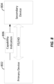
- FIG. 8 is a diagram illustrating a communication device 802 operating as a primary device in accordance with some embodiments.
- the primary device 802 may be the scheduling entity 202 or the subordinate entity 204 of FIG. 2 .
- the primary device 802 may be a UE, a base station, a network entity, a relay node, or a master device.
- the primary device 802 can communicate with a secondary device 804 in a full duplex mode or a half duplex mode.
- the secondary device 804 may be a UE, a base station, a network entity, a relay node, or a slave device.
- the primary and secondary devices 802 and 804 may be implemented using the apparatus 100.
- the primary device 802 may send a capability indication 806 to the secondary device 804 based on whether the primary device 802 is in a full duplex mode or a half duplex mode.
- features that can be indicated by the capability indication 806 may include the maximum number of bits in a data unit processed by the primary device 802 or the secondary device 804, the number of carriers aggregated for communication between the devices, a communication mode (e.g., full duplex or half duplex), a signal modulation scheme, a device category, etc.
- the capability indication 806 may be utilized to indicate any suitable capabilities or features that are supported by the primary device 802 depending on whether the primary device 802 is in a full duplex mode or a half duplex mode. In some aspects of the disclosure, the primary device 802 might not send the capability indication 806 to other devices.
- a communication device capable of sending or utilizing a capability indication may be a scheduling entity (e.g., a scheduling entity 202 of FIG. 2 ), and a device receiving the capability indication may a subordinate entity (e.g., a subordinate entity 204 of FIG. 2 ).
- the capability indication may be a signaling message or a part of a signaling message.
- a signaling protocol and its signaling messages is defined in the 3GPP Technical Specification (TS) 25.331 Release 12 document, which describes the Radio Resource Control (RRC) signaling protocol of the Universal Mobile Telecommunications System (UMTS). The entire content of this 3GPP TS is incorporated into this disclosure by reference.
- the capability indication sent to a UE may be the same or different from that sent to a base station.
- the device's capability, category, or supported features as a function of full duplex operation may be incorporated in the related communication standards (e.g., 3GPP standards) or pre-negotiated between the devices. In this case, the capability indication only needs to indicate full duplex being utilized or not, and the receiving device can assume what capabilities or features the sending device can support.
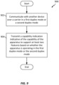
- FIG. 9 is a flow chart illustrating a method 900 of communicating capability information of an apparatus based on a communication mode in accordance with some embodiments.
- the capability information may be any of the capability indications illustrated in FIGs. 1 and 6-8 .
- the capability indication can indicate the supported features or category of the device in accordance with a communication mode.
- the communication mode may be full duplex or half duplex.
- the method 900 may be performed using any of the devices illustrated in FIGs. 1 , 2 , 4 , and/or 6-8.
- the apparatus may be a UE, a base station, or a network entity.
- the method 900 may be performed by an apparatus 100.
- the apparatus 100 communicates with another device over a carrier in a first duplex mode or a second duplex mode.
- the carrier may be a communication channel or a frequency band allocated for communication.
- the communication between the apparatus and the other device may be wireless or wired communication. Some non-limiting examples of wireless communication include cellular, Wi-Fi, Bluetooth, and satellite.
- the first duplex mode may be a full duplex mode (e.g., SF-FD), and the second duplex mode may be a half duplex mode.
- the apparatus 100 may be configured to perform full duplex communication or half duplex communication by executing the full duplex/half duplex code 124. (See FIG. 1 ). Once configured, the apparatus 100 may utilize the full duplex/half duplex control block 130 (a communication control block) and the transceiver 110 (see FIG. 1 ) to perform full duplex or half duplex communication with the other device.
- the apparatus transmits a capability indication indicative of the capability of the apparatus to support at least two features based on whether the apparatus is operating in the first duplex mode or the second duplex mode.
- the capability indication is configured to indicate support of a first feature being dependent upon a second feature, among the at least two features.
- the apparatus may configure the feature support block 128 to provide support for the first feature and the second feature.
- the features include a maximum number of bits in a data unit, a number of carriers aggregated for communication, a communication mode (e.g., full-duplex or half-duplex), a signal modulation scheme (e.g., quadrature amplitude modulation), a device category, and any features that can be configured/reconfigured (e.g., enabled/disabled) based on whether the apparatus is operating in a full duplex mode or a half duplex mode.
- the capability indication may indicate the support of the two features as illustrated in Tables 1-3.
- one feature may be full duplex, and another feature may be 256-QAM (quadrature amplitude modulation).
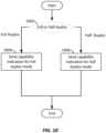
- FIG. 10 is a flow chart illustrating more detail of the block 904 of FIG. 9 in accordance with some embodiments.
- the apparatus may utilize a communication control block (e.g., the full duplex/half duplex control block 130) to determine whether the apparatus is in a full duplex mode or a half duplex mode.
- the apparatus sends a capability indication for full duplex mode.
- the full duplex mode is an SF-FD mode.
- the apparatus sends a capability indication for half duplex mode.
- the apparatus' capability as a function of full duplex/half duplex operation can be standardized or pre-negotiated. Therefore, the capability indication can indicate full duplex or half duplex without including the supported feature information because the receiving device already knows the corresponding features from the standard being used or prior negotiation.
- the capability indication may be configured to indicate that a first feature (e.g., feature A of Tables 1-3) is supported if a second feature (e.g., feature B of Tables 1-3) is not configured.
- the capability indication may be configured to indicate that the first feature is supported if the second feature is configured.
- the capability indication may be configured not to indicate support of the features individually.
- FIG. 11 is a flow chart illustrating a method 1100 of configuring an apparatus based on a capability indication received from another device in accordance with some embodiments.
- the apparatus and the other device may be a UE, a base station, or a network entity.
- the method 1100 may be performed by any of the apparatuses or devices illustrated in FIGs. 1 , 2 , 4 , and/or 6-8. In one particular example, the method 1100 may be performed by an apparatus 100 of FIG. 1 .
- an apparatus 100 communicates with another device over a carrier.
- the carrier may be a communication channel or a frequency band allocated for communication.
- the communication between the apparatus and the other device may be wireless or wired communication. Some examples of wireless communication include cellular, Wi-Fi, Bluetooth, and satellite.
- the first duplex mode may be a full duplex mode (e.g., SF-FD), and the second duplex mode may be a half duplex mode.
- the apparatus 100 may be configured to perform full duplex communication or half duplex communication by executing the full duplex/half duplex code 124. (See FIG. 1 ). Once configured, the apparatus 100 may utilize the full duplex/half duplex control block 130 and the transceiver 110 (see FIG. 1 ) to perform full duplex or half duplex communication with other devices.
- the apparatus receives a capability indication from the other device, indicative of the capability of the other device to support at least two features based on whether the other device is operating in the first duplex mode or the second duplex mode.
- the capability indication may be the same as any of the capability indications illustrated in FIGs. 1 and 6-8 .
- the apparatus is configured to support the at least two features based on the capability indication.
- the capability indication may indicate support of a first feature being dependent upon a second feature, among the at least two features.
- the apparatus may change its operation, enable/disable various features, or adjust or size available processing power based on the capability indication.
- the apparatus may enable full duplex mode and allocate more processing power if the capability indication indicates that the other device supports full duplex operation.
- the apparatus may enable half duplex mode and allocate less processing power if the capability indication indicates that the other device does not support full duplex operation.
- the apparatus may utilize the feature support block 128 to provide support for the first feature and the second feature.
- the features include a maximum number of bits in a data unit, a number of carriers aggregated for communication, a communication mode (e.g., full-duplex or half-duplex), a signal modulation scheme (e.g., quadrature amplitude modulation), a device category, and any features that can be configured/reconfigured (e.g., enabled/disabled) based on whether the apparatus is operating in a full duplex mode or a half duplex mode.
- the two features may be the features A and B of Tables 1-3.
- feature A may be full duplex
- feature B may be 256-QAM.
- LTE Long Term Evolution
- LTE-A LTE-Advanced
- CDMA2000 Evolution-Data Optimized
- UMB Ultra Mobile Broadband
- IEEE 802.11 Wi-Fi
- IEEE 802.16 WiMAX
- IEEE 802.20 Ultra-Wideband
- Bluetooth Bluetooth
- the actual telecommunication standard, network architecture, and/or communication standard employed may depend on the specific application and the overall design constraints imposed on the system.
- the word "exemplary” is used to mean “serving as an example, instance, or illustration.” Any implementation or aspect described herein as “exemplary” is not necessarily to be construed as preferred or advantageous over other aspects of the disclosure. Likewise, the term “aspects” does not require that all aspects of the disclosure include the discussed feature, advantage or mode of operation.
- the term “coupled” is used herein to refer to the direct or indirect coupling between two objects. For example, if object A physically touches object B, and object B touches object C, then objects A and C may still be considered coupled to one another-even if they do not directly physically touch each other. For instance, a first die may be coupled to a second die in a package even though the first die is never directly physically in contact with the second die.
- circuit and circuitry are used broadly, and intended to include both hardware implementations of electrical devices and conductors that, when connected and configured, enable the performance of the functions described in the present disclosure, without limitation as to the type of electronic circuits, as well as software implementations of information and instructions that, when executed by a processor, enable the performance of the functions described in the present disclosure.
- FIGs. 1-11 One or more of the components, steps, features and/or functions illustrated in FIGs. 1-11 may be rearranged and/or combined into a single component, step, feature or function or embodied in several components, steps, or functions. Additional elements, components, steps, and/or functions may also be added without departing from novel features disclosed herein.
- the apparatus, devices, and/or components illustrated in FIGs. 1-11 may be configured to perform one or more of the methods, features, or steps described herein.
- the novel algorithms described herein may also be efficiently implemented in software and/or embedded in hardware.
- a method of communicating capability information operable at an apparatus comprising communicating with another device over a carrier and transmitting a capability indication indicative of the capability of the apparatus to support at least two features based on whether the apparatus is operating in a first duplex mode or a second duplex mode, wherein the capability indication is configured to indicate support of a first feature being dependent upon a second feature, among the at least two features.
- the capability indication may be configured to indicate that the first feature is supported if the second feature is not configured.
- the capability indication may be configured to indicate that the first feature is supported if the second feature is configured.
- the capability indication may be configured not to individually indicate the support of at least some the features.
- the first duplex mode may be a same frequency full duplex (SF-FD) mode
- the second duplex mode is a half duplex mode.
- the capability indication may be configured to indicate at least one of a maximum number of bits in a data unit, a number of carriers aggregated for communication, a communication mode, a signal modulation scheme, or a device category.
- the apparatus may comprise at least one of a relay node, a user equipment, a base station, or a network entity.
- the transmitting the capability indication may comprise transmitting the capability indication to the other device that is not immediately connected to the apparatus.
- the apparatus may comprise a primary device or a secondary device.
- the capability indication may comprise a signaling message.
- a method of communication operable at an apparatus comprising communicating with another device over a carrier, ⁇ receiving a capability indication from the other device, indicative of the capability of the other device to support at least two features based on whether the other device is operating in a first duplex mode or a second duplex mode and in response to the capability indication, configuring the apparatus to support the at least two features based on the capability indication, wherein the capability indication is configured to indicate support of a first feature being dependent upon a second feature, among the at least two features.
- the capability indication may be configured to indicate that the first feature is supported if the second feature is not configured. Also, the capability indication may be configured to indicate that the first feature is supported if the second feature is configured.
- the capability indication may be configured not to individually indicate support of at least some of the features.
- the first duplex mode may be a same frequency full duplex mode, and the second duplex mode may be a half duplex mode.
- the capability indication may be configured to indicate at least one of a maximum number of bits in a data unit, a number of carriers aggregated for communication, a communication mode, a signal modulation scheme, or a device category.
- the apparatus may comprise at least one of a relay node, a user equipment, a base station, or a network entity.
- the apparatus may comprise a primary device or a secondary device.
- the capability indication may comprise a signaling message.
- an apparatus configured for communication with another device, the apparatus comprising means for communicating with the other device over a carrier and means for transmitting a capability indication indicative of the capability of the apparatus to support at least two features based on whether the apparatus is operating in a first duplex mode or a second duplex mode, wherein the capability indication is configured to indicate support of a first feature being dependent upon a second feature, among the at least two features.
- an apparatus configured for communication with another device, the apparatus comprising means for communicating with the other device over a carrier, means for receiving a capability indication from the other device, indicative of the capability of the other device to support at least two features based on whether the other device is operating in a first duplex mode or a second duplex mode and means for, in response to the capability indication, configuring the apparatus to support the at least two features based on the capability indication, wherein the capability indication is configured to indicate support of a first feature being dependent upon a second feature, among the at least two features.
- an apparatus comprising a communication interface, a memory comprising code and at least one processor coupled to the communication interface and the memory, wherein the processor when executing the code comprises a communication control block configured to utilize the communication interface to communicate with another device over a carrier and a capability indication block configured to transmit a capability indication indicative of the capability of the apparatus to support at least two features based on whether the apparatus is operating in a first duplex mode or a second duplex mode, wherein the capability indication is configured to indicate support of a first feature being dependent upon a second feature, among the at least two features.
- an apparatus comprising a communication interface, a memory comprising code and at least one processor coupled to the communication interface and the memory, wherein the processor when executing the code comprises a communication control block configured to utilize the communication interface to communicate with another device over a carrier, a capability indication block configured to receive a capability indication from the other device, indicative of the capability of the other device to support at least two features based on whether the other device is operating in a first duplex mode or a second duplex mode and a configuration control block, in response to the capability indication, configured to configure the apparatus to support the at least two features based on the capability indication, wherein the capability indication is configured to indicate support of a first feature being dependent upon a second feature, among the at least two features.
- a communication system comprising a plurality of communication devices configured for wireless communication
- the system comprising a first communication device and a second communication device, configured to communicate with each other utilizing a carrier, wherein the first communication device receives a capability indication from the second communication device, indicative of the capability of the second communication device to support at least two features based on whether the second communication device is operating in a first duplex mode or a second duplex mode, wherein in response to the capability indication, the first communication device is configured to support the at least two features based on the capability indication, and wherein the capability indication is configured to indicate support of a first feature being dependent upon a second feature, among the at least two features.
Landscapes
- Engineering & Computer Science (AREA)
- Signal Processing (AREA)
- Computer Networks & Wireless Communication (AREA)
- Databases & Information Systems (AREA)
- Mobile Radio Communication Systems (AREA)
- Telephone Function (AREA)
Applications Claiming Priority (3)
| Application Number | Priority Date | Filing Date | Title |
|---|---|---|---|
| US201462014027P | 2014-06-18 | 2014-06-18 | |
| US14/567,940 US10841070B2 (en) | 2014-06-18 | 2014-12-11 | Apparatus and method for capability update in wireless communication |
| PCT/US2015/034913 WO2015195414A1 (en) | 2014-06-18 | 2015-06-09 | Apparatus and method for capability update in wireless communication |
Publications (2)
| Publication Number | Publication Date |
|---|---|
| EP3158810A1 EP3158810A1 (en) | 2017-04-26 |
| EP3158810B1 true EP3158810B1 (en) | 2023-07-26 |
Family
ID=54870629
Family Applications (1)
| Application Number | Title | Priority Date | Filing Date |
|---|---|---|---|
| EP15795001.5A Active EP3158810B1 (en) | 2014-06-18 | 2015-06-09 | Apparatus and method for capability update in wireless communication |
Country Status (8)
| Country | Link |
|---|---|
| US (1) | US10841070B2 (enExample) |
| EP (1) | EP3158810B1 (enExample) |
| JP (1) | JP6561076B2 (enExample) |
| KR (1) | KR102234322B1 (enExample) |
| CN (1) | CN106465390B (enExample) |
| BR (1) | BR112016029308B1 (enExample) |
| TW (1) | TW201603545A (enExample) |
| WO (1) | WO2015195414A1 (enExample) |
Families Citing this family (12)
| Publication number | Priority date | Publication date | Assignee | Title |
|---|---|---|---|---|
| WO2018164885A1 (en) * | 2017-03-10 | 2018-09-13 | Kyocera Corporation | Bulk rach machine type communication (mtc) transmissions |
| TWI638533B (zh) * | 2017-07-10 | 2018-10-11 | 瑞昱半導體股份有限公司 | 無線通訊裝置 |
| CN109274399B (zh) * | 2017-07-17 | 2020-03-06 | 瑞昱半导体股份有限公司 | 无线通信装置 |
| DE102017213166B3 (de) * | 2017-07-31 | 2018-10-25 | Volkswagen Aktiengesellschaft | Verfahren zum Betreiben einer Mobilfunkstation, Mobilfunkstation sowie Computerprogramm |
| US11838928B2 (en) * | 2018-11-02 | 2023-12-05 | Qualcomm Incorporated | Dynamic resource management |
| WO2020206572A1 (en) * | 2019-04-06 | 2020-10-15 | Qualcomm Incorporated | Communicating multiple transport formats in a slot with full-duplex |
| US11463869B2 (en) * | 2019-12-06 | 2022-10-04 | Qualcomm Incorporated | Dual-mode half duplex time division duplex and full duplex frequency division duplex capable user equipment |
| US11831389B2 (en) | 2020-08-04 | 2023-11-28 | Qualcomm Incorporated | Techniques for reporting repeater communication capability |
| WO2022147636A1 (en) * | 2021-01-05 | 2022-07-14 | Qualcomm Incorporated | Resource activation and deactivation for different duplexing modes |
| US11877354B2 (en) * | 2021-07-08 | 2024-01-16 | Qualcomm Incorporated | Assistance information for full-duplex relay user equipment selection |
| CN116700880A (zh) * | 2022-02-25 | 2023-09-05 | 戴尔产品有限公司 | 系统功能管理方法、电子设备和计算机程序产品 |
| US20250023663A1 (en) * | 2023-07-11 | 2025-01-16 | Sony Semiconductor Solutions Corporation | Communication apparatus and communication system |
Family Cites Families (31)
| Publication number | Priority date | Publication date | Assignee | Title |
|---|---|---|---|---|
| US4607364A (en) * | 1983-11-08 | 1986-08-19 | Jeffrey Neumann | Multimode data communication system |
| US7068609B2 (en) | 2000-08-09 | 2006-06-27 | Broadcom Corporation | Method and apparatus for performing wire speed auto-negotiation |
| JP4593618B2 (ja) * | 2005-03-08 | 2010-12-08 | パナソニック株式会社 | パケット送信装置 |
| US9019934B2 (en) | 2007-10-24 | 2015-04-28 | Hmicro, Inc. | Systems and networks for half and full duplex wireless communication using multiple radios |
| KR101533295B1 (ko) * | 2008-04-23 | 2015-07-03 | 삼성전자주식회사 | 이동통신 시스템에서 전이중 방식을 사용하는 중계국의 네트워크 진입을 위한 장치 및 방법 |
| US8542617B2 (en) * | 2008-06-02 | 2013-09-24 | Apple Inc. | Adaptive operational full-duplex and half-duplex FDD modes in wireless networks |
| KR101502561B1 (ko) * | 2008-09-12 | 2015-03-25 | 삼성전자주식회사 | 전 이중 방식 릴레이와 반 이중 방식 릴레이가 공존하는 시스템을 위한 프레임 구성 장치 및 방법 |
| US9232452B2 (en) | 2008-10-31 | 2016-01-05 | Htc Corporation | Method of handling an inter rat handover in wireless communication system and related communication device |
| JP5559786B2 (ja) * | 2009-06-25 | 2014-07-23 | 株式会社日立製作所 | 基地局、無線通信システム、無線リソース割り当て方法、ならびに無線通信方法 |
| WO2011040763A2 (ko) | 2009-09-29 | 2011-04-07 | 한국전자통신연구원 | 무선 통신 시스템에서 릴레이 링크 셋업 방법 및 장치 |
| US8768397B2 (en) * | 2009-10-02 | 2014-07-01 | Sharp Kabushiki Kaisha | Transmission power control on a wireless communication device for a plurality of regulated bands or component carriers |
| KR101735832B1 (ko) * | 2010-11-15 | 2017-05-15 | 삼성전자주식회사 | 무선 통신 시스템에서 단말의 속도를 이용하여 통신하는 방법 및 장치 |
| CN103329629B (zh) * | 2010-12-22 | 2016-01-20 | 皇家飞利浦电子股份有限公司 | 连网照明系统控制 |
| WO2012115557A1 (en) | 2011-02-22 | 2012-08-30 | Telefonaktiebolaget L M Ericsson (Publ) | Positioning devices and methods in cellular communication systems |
| JP5769008B2 (ja) * | 2011-06-07 | 2015-08-26 | 日本電気株式会社 | 通信処理システム、位置登録方法、移動中継局およびその制御方法と制御プログラム |
| US9014110B2 (en) * | 2011-07-18 | 2015-04-21 | Qualcomm Incorporated | Enabling half-duplex operation |
| KR101990134B1 (ko) | 2011-08-10 | 2019-06-17 | 삼성전자주식회사 | 듀얼 모드 단말의 성능 정보 보고 방법 및 장치 |
| US9277398B2 (en) | 2011-08-22 | 2016-03-01 | Sharp Kabushiki Kaisha | User equipment capability signaling |
| EP2761956A1 (en) * | 2011-09-26 | 2014-08-06 | Interdigital Patent Holdings, Inc. | Inter -band carrier aggregation |
| US9131524B2 (en) * | 2011-10-03 | 2015-09-08 | Qualcomm Incorporated | Half-duplex/full-duplex operation for TDD carrier aggregation |
| US9246662B2 (en) | 2011-11-04 | 2016-01-26 | Nokia Solutions And Networks Oy | Mechanisms addressing dynamic component carrier change in relay systems |
| KR101920496B1 (ko) * | 2011-11-25 | 2018-11-21 | 애플 인크. | 인터밴드 tdd 전송 방식에서 사용자 단말의 전송 모드 정보를 송수신하는 방법 및 장치 |
| US9949166B2 (en) | 2012-01-23 | 2018-04-17 | Intel Corporation | Extended access barring (EAB) signaling for a core network (CN) and node |
| GB2499259A (en) | 2012-02-13 | 2013-08-14 | Renesas Mobile Corp | Scheduling a User Device for half-duplex or full-duplex operation based on the self-interference cancellation capability of the device |
| EP2891265B1 (en) | 2012-08-28 | 2023-07-05 | InterDigital Patent Holdings, Inc. | Full duplex single channel communications |
| US9003158B2 (en) * | 2012-10-19 | 2015-04-07 | Freescale Semiconductor, Inc. | Flexible control mechanism for store gathering in a write buffer |
| EP2739108B1 (en) | 2012-11-28 | 2019-01-02 | Samsung Electronics Co., Ltd | Method and apparatus for performing communication in a wireless communication system |
| US9872290B2 (en) * | 2012-12-14 | 2018-01-16 | Huawei Technologies Co., Ltd. | System and method for terminal cooperation based on sparse multi-dimensional spreading |
| US9319188B2 (en) * | 2013-01-17 | 2016-04-19 | Sharp Laboratories Of America, Inc. | Systems and methods for special subframe configuration for carrier aggregation |
| JP6371391B2 (ja) * | 2013-07-30 | 2018-08-08 | ソニー株式会社 | リピータ機能の有効化要求の方法およびユーザ機器 |
| US9985773B2 (en) * | 2014-05-16 | 2018-05-29 | Qualcomm Incorporated | Techniques for performing half/full-duplex operations in wireless communications |
-
2014
- 2014-12-11 US US14/567,940 patent/US10841070B2/en active Active
-
2015
- 2015-06-09 BR BR112016029308-8A patent/BR112016029308B1/pt active IP Right Grant
- 2015-06-09 CN CN201580032381.4A patent/CN106465390B/zh active Active
- 2015-06-09 KR KR1020167034862A patent/KR102234322B1/ko active Active
- 2015-06-09 JP JP2016573080A patent/JP6561076B2/ja active Active
- 2015-06-09 EP EP15795001.5A patent/EP3158810B1/en active Active
- 2015-06-09 WO PCT/US2015/034913 patent/WO2015195414A1/en not_active Ceased
- 2015-06-10 TW TW104118836A patent/TW201603545A/zh unknown
Also Published As
| Publication number | Publication date |
|---|---|
| CN106465390A (zh) | 2017-02-22 |
| JP6561076B2 (ja) | 2019-08-14 |
| EP3158810A1 (en) | 2017-04-26 |
| BR112016029308B1 (pt) | 2024-02-27 |
| WO2015195414A1 (en) | 2015-12-23 |
| JP2017525205A (ja) | 2017-08-31 |
| TW201603545A (zh) | 2016-01-16 |
| US10841070B2 (en) | 2020-11-17 |
| US20150372801A1 (en) | 2015-12-24 |
| KR102234322B1 (ko) | 2021-03-30 |
| CN106465390B (zh) | 2019-11-12 |
| BR112016029308A2 (pt) | 2017-08-22 |
| KR20170020348A (ko) | 2017-02-22 |
Similar Documents
| Publication | Publication Date | Title |
|---|---|---|
| EP3158810B1 (en) | Apparatus and method for capability update in wireless communication | |
| US20220166498A1 (en) | Resource coordination for integrated access and backhaul | |
| EP2826291B1 (en) | Intra-qci scheduler and method for intra-qci scheduling in a wireless access network | |
| US10349460B2 (en) | Dual active connections over single radio user equipment | |
| US11032832B2 (en) | Time-division multiplexing for cellular dual connectivity | |
| CN106465388A (zh) | 用于获得和使用装置到装置频率有关能力和配置偏好的系统和方法 | |
| EP3100490A1 (en) | A master base station device configured to provide control plane connectivity to a user device whilst user plane connectivity is provided to the user device by a secondary base station device | |
| US12063598B2 (en) | Reduced power consumption by obtaining time domain resource allocation patterns in advance via additional signaling | |
| US11368891B2 (en) | Primary cell switching in non-simultaneous uplink carrier aggregation scenarios | |
| JP2022511174A (ja) | デフォルトのpucch及びsrsビームの判定 | |
| US12200524B2 (en) | Flexible downlink control signal monitoring in wireless communications | |
| US10966221B2 (en) | Uplink scheduling with WLAN/3GPP aggregation | |
| US20200068588A1 (en) | Methods and apparatus for interference management of wireless links with overriding link priority | |
| CN117998622A (zh) | 频域部分传输 |
Legal Events
| Date | Code | Title | Description |
|---|---|---|---|
| STAA | Information on the status of an ep patent application or granted ep patent |
Free format text: STATUS: THE INTERNATIONAL PUBLICATION HAS BEEN MADE |
|
| PUAI | Public reference made under article 153(3) epc to a published international application that has entered the european phase |
Free format text: ORIGINAL CODE: 0009012 |
|
| STAA | Information on the status of an ep patent application or granted ep patent |
Free format text: STATUS: REQUEST FOR EXAMINATION WAS MADE |
|
| 17P | Request for examination filed |
Effective date: 20161109 |
|
| AK | Designated contracting states |
Kind code of ref document: A1 Designated state(s): AL AT BE BG CH CY CZ DE DK EE ES FI FR GB GR HR HU IE IS IT LI LT LU LV MC MK MT NL NO PL PT RO RS SE SI SK SM TR |
|
| AX | Request for extension of the european patent |
Extension state: BA ME |
|
| DAV | Request for validation of the european patent (deleted) | ||
| DAX | Request for extension of the european patent (deleted) | ||
| STAA | Information on the status of an ep patent application or granted ep patent |
Free format text: STATUS: EXAMINATION IS IN PROGRESS |
|
| 17Q | First examination report despatched |
Effective date: 20171103 |
|
| GRAP | Despatch of communication of intention to grant a patent |
Free format text: ORIGINAL CODE: EPIDOSNIGR1 |
|
| STAA | Information on the status of an ep patent application or granted ep patent |
Free format text: STATUS: GRANT OF PATENT IS INTENDED |
|
| INTG | Intention to grant announced |
Effective date: 20221031 |
|
| GRAJ | Information related to disapproval of communication of intention to grant by the applicant or resumption of examination proceedings by the epo deleted |
Free format text: ORIGINAL CODE: EPIDOSDIGR1 |
|
| STAA | Information on the status of an ep patent application or granted ep patent |
Free format text: STATUS: EXAMINATION IS IN PROGRESS |
|
| INTC | Intention to grant announced (deleted) | ||
| GRAP | Despatch of communication of intention to grant a patent |
Free format text: ORIGINAL CODE: EPIDOSNIGR1 |
|
| STAA | Information on the status of an ep patent application or granted ep patent |
Free format text: STATUS: GRANT OF PATENT IS INTENDED |
|
| INTG | Intention to grant announced |
Effective date: 20230316 |
|
| GRAS | Grant fee paid |
Free format text: ORIGINAL CODE: EPIDOSNIGR3 |
|
| GRAA | (expected) grant |
Free format text: ORIGINAL CODE: 0009210 |
|
| STAA | Information on the status of an ep patent application or granted ep patent |
Free format text: STATUS: THE PATENT HAS BEEN GRANTED |
|
| AK | Designated contracting states |
Kind code of ref document: B1 Designated state(s): AL AT BE BG CH CY CZ DE DK EE ES FI FR GB GR HR HU IE IS IT LI LT LU LV MC MK MT NL NO PL PT RO RS SE SI SK SM TR |
|
| REG | Reference to a national code |
Ref country code: GB Ref legal event code: FG4D |
|
| REG | Reference to a national code |
Ref country code: CH Ref legal event code: EP |
|
| REG | Reference to a national code |
Ref country code: DE Ref legal event code: R096 Ref document number: 602015084790 Country of ref document: DE |
|
| REG | Reference to a national code |
Ref country code: IE Ref legal event code: FG4D |
|
| REG | Reference to a national code |
Ref country code: LT Ref legal event code: MG9D |
|
| REG | Reference to a national code |
Ref country code: NL Ref legal event code: MP Effective date: 20230726 |
|
| REG | Reference to a national code |
Ref country code: AT Ref legal event code: MK05 Ref document number: 1593420 Country of ref document: AT Kind code of ref document: T Effective date: 20230726 |
|
| PG25 | Lapsed in a contracting state [announced via postgrant information from national office to epo] |
Ref country code: NL Free format text: LAPSE BECAUSE OF FAILURE TO SUBMIT A TRANSLATION OF THE DESCRIPTION OR TO PAY THE FEE WITHIN THE PRESCRIBED TIME-LIMIT Effective date: 20230726 |
|
| PG25 | Lapsed in a contracting state [announced via postgrant information from national office to epo] |
Ref country code: GR Free format text: LAPSE BECAUSE OF FAILURE TO SUBMIT A TRANSLATION OF THE DESCRIPTION OR TO PAY THE FEE WITHIN THE PRESCRIBED TIME-LIMIT Effective date: 20231027 |
|
| PG25 | Lapsed in a contracting state [announced via postgrant information from national office to epo] |
Ref country code: IS Free format text: LAPSE BECAUSE OF FAILURE TO SUBMIT A TRANSLATION OF THE DESCRIPTION OR TO PAY THE FEE WITHIN THE PRESCRIBED TIME-LIMIT Effective date: 20231126 |
|
| PG25 | Lapsed in a contracting state [announced via postgrant information from national office to epo] |
Ref country code: SE Free format text: LAPSE BECAUSE OF FAILURE TO SUBMIT A TRANSLATION OF THE DESCRIPTION OR TO PAY THE FEE WITHIN THE PRESCRIBED TIME-LIMIT Effective date: 20230726 Ref country code: RS Free format text: LAPSE BECAUSE OF FAILURE TO SUBMIT A TRANSLATION OF THE DESCRIPTION OR TO PAY THE FEE WITHIN THE PRESCRIBED TIME-LIMIT Effective date: 20230726 Ref country code: PT Free format text: LAPSE BECAUSE OF FAILURE TO SUBMIT A TRANSLATION OF THE DESCRIPTION OR TO PAY THE FEE WITHIN THE PRESCRIBED TIME-LIMIT Effective date: 20231127 Ref country code: NO Free format text: LAPSE BECAUSE OF FAILURE TO SUBMIT A TRANSLATION OF THE DESCRIPTION OR TO PAY THE FEE WITHIN THE PRESCRIBED TIME-LIMIT Effective date: 20231026 Ref country code: LV Free format text: LAPSE BECAUSE OF FAILURE TO SUBMIT A TRANSLATION OF THE DESCRIPTION OR TO PAY THE FEE WITHIN THE PRESCRIBED TIME-LIMIT Effective date: 20230726 Ref country code: LT Free format text: LAPSE BECAUSE OF FAILURE TO SUBMIT A TRANSLATION OF THE DESCRIPTION OR TO PAY THE FEE WITHIN THE PRESCRIBED TIME-LIMIT Effective date: 20230726 Ref country code: IS Free format text: LAPSE BECAUSE OF FAILURE TO SUBMIT A TRANSLATION OF THE DESCRIPTION OR TO PAY THE FEE WITHIN THE PRESCRIBED TIME-LIMIT Effective date: 20231126 Ref country code: HR Free format text: LAPSE BECAUSE OF FAILURE TO SUBMIT A TRANSLATION OF THE DESCRIPTION OR TO PAY THE FEE WITHIN THE PRESCRIBED TIME-LIMIT Effective date: 20230726 Ref country code: GR Free format text: LAPSE BECAUSE OF FAILURE TO SUBMIT A TRANSLATION OF THE DESCRIPTION OR TO PAY THE FEE WITHIN THE PRESCRIBED TIME-LIMIT Effective date: 20231027 Ref country code: FI Free format text: LAPSE BECAUSE OF FAILURE TO SUBMIT A TRANSLATION OF THE DESCRIPTION OR TO PAY THE FEE WITHIN THE PRESCRIBED TIME-LIMIT Effective date: 20230726 Ref country code: AT Free format text: LAPSE BECAUSE OF FAILURE TO SUBMIT A TRANSLATION OF THE DESCRIPTION OR TO PAY THE FEE WITHIN THE PRESCRIBED TIME-LIMIT Effective date: 20230726 |
|
| PG25 | Lapsed in a contracting state [announced via postgrant information from national office to epo] |
Ref country code: PL Free format text: LAPSE BECAUSE OF FAILURE TO SUBMIT A TRANSLATION OF THE DESCRIPTION OR TO PAY THE FEE WITHIN THE PRESCRIBED TIME-LIMIT Effective date: 20230726 |
|
| PG25 | Lapsed in a contracting state [announced via postgrant information from national office to epo] |
Ref country code: ES Free format text: LAPSE BECAUSE OF FAILURE TO SUBMIT A TRANSLATION OF THE DESCRIPTION OR TO PAY THE FEE WITHIN THE PRESCRIBED TIME-LIMIT Effective date: 20230726 |
|
| REG | Reference to a national code |
Ref country code: DE Ref legal event code: R097 Ref document number: 602015084790 Country of ref document: DE |
|
| PG25 | Lapsed in a contracting state [announced via postgrant information from national office to epo] |
Ref country code: SM Free format text: LAPSE BECAUSE OF FAILURE TO SUBMIT A TRANSLATION OF THE DESCRIPTION OR TO PAY THE FEE WITHIN THE PRESCRIBED TIME-LIMIT Effective date: 20230726 Ref country code: RO Free format text: LAPSE BECAUSE OF FAILURE TO SUBMIT A TRANSLATION OF THE DESCRIPTION OR TO PAY THE FEE WITHIN THE PRESCRIBED TIME-LIMIT Effective date: 20230726 Ref country code: ES Free format text: LAPSE BECAUSE OF FAILURE TO SUBMIT A TRANSLATION OF THE DESCRIPTION OR TO PAY THE FEE WITHIN THE PRESCRIBED TIME-LIMIT Effective date: 20230726 Ref country code: EE Free format text: LAPSE BECAUSE OF FAILURE TO SUBMIT A TRANSLATION OF THE DESCRIPTION OR TO PAY THE FEE WITHIN THE PRESCRIBED TIME-LIMIT Effective date: 20230726 Ref country code: DK Free format text: LAPSE BECAUSE OF FAILURE TO SUBMIT A TRANSLATION OF THE DESCRIPTION OR TO PAY THE FEE WITHIN THE PRESCRIBED TIME-LIMIT Effective date: 20230726 Ref country code: CZ Free format text: LAPSE BECAUSE OF FAILURE TO SUBMIT A TRANSLATION OF THE DESCRIPTION OR TO PAY THE FEE WITHIN THE PRESCRIBED TIME-LIMIT Effective date: 20230726 Ref country code: SK Free format text: LAPSE BECAUSE OF FAILURE TO SUBMIT A TRANSLATION OF THE DESCRIPTION OR TO PAY THE FEE WITHIN THE PRESCRIBED TIME-LIMIT Effective date: 20230726 |
|
| PG25 | Lapsed in a contracting state [announced via postgrant information from national office to epo] |
Ref country code: IT Free format text: LAPSE BECAUSE OF FAILURE TO SUBMIT A TRANSLATION OF THE DESCRIPTION OR TO PAY THE FEE WITHIN THE PRESCRIBED TIME-LIMIT Effective date: 20230726 |
|
| PLBE | No opposition filed within time limit |
Free format text: ORIGINAL CODE: 0009261 |
|
| STAA | Information on the status of an ep patent application or granted ep patent |
Free format text: STATUS: NO OPPOSITION FILED WITHIN TIME LIMIT |
|
| 26N | No opposition filed |
Effective date: 20240429 |
|
| PGFP | Annual fee paid to national office [announced via postgrant information from national office to epo] |
Ref country code: GB Payment date: 20240509 Year of fee payment: 10 |
|
| PGFP | Annual fee paid to national office [announced via postgrant information from national office to epo] |
Ref country code: DE Payment date: 20240509 Year of fee payment: 10 |
|
| PG25 | Lapsed in a contracting state [announced via postgrant information from national office to epo] |
Ref country code: SI Free format text: LAPSE BECAUSE OF FAILURE TO SUBMIT A TRANSLATION OF THE DESCRIPTION OR TO PAY THE FEE WITHIN THE PRESCRIBED TIME-LIMIT Effective date: 20230726 |
|
| PGFP | Annual fee paid to national office [announced via postgrant information from national office to epo] |
Ref country code: FR Payment date: 20240509 Year of fee payment: 10 |
|
| PG25 | Lapsed in a contracting state [announced via postgrant information from national office to epo] |
Ref country code: BG Free format text: LAPSE BECAUSE OF FAILURE TO SUBMIT A TRANSLATION OF THE DESCRIPTION OR TO PAY THE FEE WITHIN THE PRESCRIBED TIME-LIMIT Effective date: 20230726 |
|
| PG25 | Lapsed in a contracting state [announced via postgrant information from national office to epo] |
Ref country code: BG Free format text: LAPSE BECAUSE OF FAILURE TO SUBMIT A TRANSLATION OF THE DESCRIPTION OR TO PAY THE FEE WITHIN THE PRESCRIBED TIME-LIMIT Effective date: 20230726 |
|
| PG25 | Lapsed in a contracting state [announced via postgrant information from national office to epo] |
Ref country code: MC Free format text: LAPSE BECAUSE OF FAILURE TO SUBMIT A TRANSLATION OF THE DESCRIPTION OR TO PAY THE FEE WITHIN THE PRESCRIBED TIME-LIMIT Effective date: 20230726 |
|
| REG | Reference to a national code |
Ref country code: CH Ref legal event code: PL |
|
| PG25 | Lapsed in a contracting state [announced via postgrant information from national office to epo] |
Ref country code: LU Free format text: LAPSE BECAUSE OF NON-PAYMENT OF DUE FEES Effective date: 20240609 |
|
| PG25 | Lapsed in a contracting state [announced via postgrant information from national office to epo] |
Ref country code: IE Free format text: LAPSE BECAUSE OF NON-PAYMENT OF DUE FEES Effective date: 20240609 |
|
| PG25 | Lapsed in a contracting state [announced via postgrant information from national office to epo] |
Ref country code: BE Free format text: LAPSE BECAUSE OF NON-PAYMENT OF DUE FEES Effective date: 20240630 Ref country code: CH Free format text: LAPSE BECAUSE OF NON-PAYMENT OF DUE FEES Effective date: 20240630 |
|
| REG | Reference to a national code |
Ref country code: BE Ref legal event code: MM Effective date: 20240630 |
|
| PG25 | Lapsed in a contracting state [announced via postgrant information from national office to epo] |
Ref country code: CY Free format text: LAPSE BECAUSE OF FAILURE TO SUBMIT A TRANSLATION OF THE DESCRIPTION OR TO PAY THE FEE WITHIN THE PRESCRIBED TIME-LIMIT; INVALID AB INITIO Effective date: 20150609 |