EP3158750B1 - Intrablockkopie-blockvektorsignalisierung zur videokodierung - Google Patents
Intrablockkopie-blockvektorsignalisierung zur videokodierung Download PDFInfo
- Publication number
- EP3158750B1 EP3158750B1 EP15734769.1A EP15734769A EP3158750B1 EP 3158750 B1 EP3158750 B1 EP 3158750B1 EP 15734769 A EP15734769 A EP 15734769A EP 3158750 B1 EP3158750 B1 EP 3158750B1
- Authority
- EP
- European Patent Office
- Prior art keywords
- bvd
- component
- block
- video
- value
- Prior art date
- Legal status (The legal status is an assumption and is not a legal conclusion. Google has not performed a legal analysis and makes no representation as to the accuracy of the status listed.)
- Active
Links
Images


Classifications
-
- H—ELECTRICITY
- H04—ELECTRIC COMMUNICATION TECHNIQUE
- H04N—PICTORIAL COMMUNICATION, e.g. TELEVISION
- H04N19/00—Methods or arrangements for coding, decoding, compressing or decompressing digital video signals
- H04N19/50—Methods or arrangements for coding, decoding, compressing or decompressing digital video signals using predictive coding
- H04N19/503—Methods or arrangements for coding, decoding, compressing or decompressing digital video signals using predictive coding involving temporal prediction
- H04N19/51—Motion estimation or motion compensation
- H04N19/513—Processing of motion vectors
- H04N19/517—Processing of motion vectors by encoding
- H04N19/52—Processing of motion vectors by encoding by predictive encoding
-
- H—ELECTRICITY
- H04—ELECTRIC COMMUNICATION TECHNIQUE
- H04N—PICTORIAL COMMUNICATION, e.g. TELEVISION
- H04N19/00—Methods or arrangements for coding, decoding, compressing or decompressing digital video signals
- H04N19/50—Methods or arrangements for coding, decoding, compressing or decompressing digital video signals using predictive coding
- H04N19/593—Methods or arrangements for coding, decoding, compressing or decompressing digital video signals using predictive coding involving spatial prediction techniques
Definitions
- This disclosure relates to video encoding and video decoding.
- Video compression techniques perform spatial (intra picture) prediction and/or temporal (inter picture) prediction to reduce or remove redundancy inherent in video sequences.
- a video slice i.e., a video frame or a portion of a video frame
- video blocks which may also be referred to as treeblocks, coding units (CUs) and/or coding nodes.
- Video blocks in an intra coded (I) slice of a picture are encoded using spatial prediction with respect to reference samples in neighboring blocks in the same picture.
- Video blocks in an inter coded (P or B) slice of a picture may use spatial prediction with respect to reference samples in neighboring blocks in the same picture or temporal prediction with respect to reference samples in other reference pictures.
- Pictures may be referred to as frames, and reference pictures may be referred to as reference frames.
- Residual data represents pixel differences between the original block to be coded and the predictive block.
- An inter coded block is encoded according to a motion vector that points to a block of reference samples forming the predictive block, and the residual data indicating the difference between the coded block and the predictive block.
- An intra coded block is encoded according to an intra coding mode and the residual data.
- the residual data may be transformed from the pixel domain to a transform domain, resulting in residual transform coefficients, which then may be quantized.
- the quantized transform coefficients initially arranged in a two-dimensional array, may be scanned in order to produce a one-dimensional vector of transform coefficients, and entropy coding may be applied to achieve even more compression.
- Intra BC refers to prediction techniques in which a current video block is coded based on a prediction block within the same picture.
- the prediction block within the same picture is identified by a vector, which may be referred to as a block vector difference.
- a block vector difference that identifies a prediction block may be represented by a plurality of syntax elements, which may be encoded and decoded.
- This disclosure proposes various techniques whereby a video encoder may conditionally signal syntax elements representing the absolute value and/or sign of the components of the block vector difference.
- a video decoder may be configured to infer the values of the syntax elements representing the absolute value and/or sign of the components of the block vector difference when such syntax elements are not signaled.
- a method of decoding video data comprises receiving, in an encoded video bitstream, an encoded block of video data encoded using an intra BC mode, decoding a first absolute value of a first component of a block vector difference (BVD) associated with the encoded block of video data, decoding a second absolute value of a second component of the BVD associated with the encoded block of video data, decoding a first sign value for the first component of the BVD, inferring a second sign value for the second component of the BVD based on one or more video coding characteristics indicating that the second sign value is restricted to one value, determining the BVD based on the decoded first absolute value of the first component of the BVD, the decoded second absolute value of the second component of the BVD, the decoded first sign value for the first component of the BVD, and the inferred second sign value for the second component of the BVD, determining a block vector from the BVD and a block vector predictor, and
- decoding the first absolute value of the first component of the BVD comprises receiving a first syntax element associated with the first absolute value of the first component of the BVD, inferring that a value of the first syntax element represents the first absolute value of the first component of the BVD minus an offset based on the one or more video coding characteristics indicating that the first absolute value of the first component is greater than the offset, and determining the first absolute value of the first component by adding the value of the first syntax element to the offset.
- a method of encoding video data comprises encoding a first absolute value of a first component of a BVD associated with a block of video data encoded with intra BC mode, encoding a second absolute value of a second component of the BVD associated with the block of video data, encoding a first sign value for the first component of the BVD, not encoding a second sign value for the second component of the BVD based on one or more video coding characteristics indicating that the second sign value is restricted to one value, and generating syntax elements for the first absolute value, the second absolute value, and the first sign value.
- This disclosure proposes various methods, techniques, and apparatuses for intra Block Copy (BC) block vector coding.
- the techniques described herein improve intra BC block vector coding by removing redundancies and improving other aspects of intra BC block vector coding.
- the techniques of this disclosure may be used in any video coding process that utilizes an intra BC mode, including extensions of the high efficiency video coding (HEVC) standard (e.g. screen content coding extensions).
- HEVC high efficiency video coding
- Certain examples of this disclosure may also be applicable to HEVC and its eextensions, in general, including the support for higher bit depths (e.g., more than 8 bits), as well as support for higher chroma sampling formats (e.g., 4:4:4 and 4:2:2 chroma sub-sampling formats).
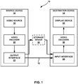
- FIG. 1 is a block diagram illustrating an example video encoding and decoding system 10 that may utilize the techniques for intra BC block vector coding described in this disclosure.
- system 10 includes a source device 12 that generates encoded video data to be decoded at a later time by a destination device 14.
- Source device 12 and destination device 14 may comprise any of a wide range of devices, including wireless communication devices, cellular telephones (communicating via a cellular communication standard), desktop computers, notebook (i.e., laptop) computers, tablet computers, set-top boxes, telephone handsets such as so-called “smart” phones, so-called “smart” pads, televisions, cameras, display devices, digital media players, video gaming consoles, video streaming device, or the like.
- source device 12 and destination device 14 may be equipped for wireless communication.
- Link 16 may comprise any type of medium or device capable of moving the encoded video data from source device 12 to destination device 14.
- link 16 may comprise a communication medium to enable source device 12 to transmit encoded video data directly to destination device 14 in real-time.
- the encoded video data may be modulated and demodulated according to a communication standard, such as a wireless communication protocol, and transmitted to destination device 14.
- the communication medium may comprise any wireless or wired communication medium, such as a radio frequency (RF) spectrum or one or more physical transmission lines.
- the communication medium may form part of a packet-based network, such as a local area network, a wide-area network, or a global network such as the Internet.
- the communication medium may include routers, switches, base stations, or any other equipment that may be useful to facilitate communication from source device 12 to destination device 14.
- encoded data may be output from output interface 22 to a storage device 32.
- encoded data may be accessed from storage device 32 by input interface.
- Storage device 32 may include any of a variety of distributed or locally accessed data storage media such as a hard drive, Blu-ray discs, DVDs, CD-ROMs, flash memory, volatile or non-volatile memory, or any other suitable digital storage media for storing encoded video data.
- storage device 32 may correspond to a file server or another intermediate storage device that may hold the encoded video generated by source device 12.
- Destination device 14 may access stored video data from storage device 32 via streaming or download.
- the file server may be any type of server capable of storing encoded video data and transmitting that encoded video data to the destination device 14.
- Example file servers include a web server (e.g., for a website), an FTP server, network attached storage (NAS) devices, or a local disk drive.
- Destination device 14 may access the encoded video data through any standard data connection, including an Internet connection. This may include a wireless channel (e.g., a Wi-Fi connection), a wired connection (e.g., DSL, cable modem, etc.), or a combination of both that is suitable for accessing encoded video data stored on a file server.
- the transmission of encoded video data from storage device 32 may be a streaming transmission, a download transmission, or a combination of both.
- the techniques of this disclosure for intra BC block vector coding are not necessarily limited to wireless applications or settings.
- the techniques may be applied to video coding in support of any of a variety of multimedia applications, such as over-the-air television broadcasts, cable television transmissions, satellite television transmissions, streaming video transmissions, e.g., via the Internet, encoding of digital video for storage on a data storage medium, decoding of digital video stored on a data storage medium, or other applications.
- system 10 may be configured to support one-way or two-way video transmission to support applications such as video streaming, video playback, video broadcasting, and/or video telephony.
- source device 12 includes a video source 18, video encoder 20 and an output interface 22.
- output interface 22 may include a modulator/demodulator (modem) and/or a transmitter.
- video source 18 may include a source such as a video capture device, e.g., a video camera, a video archive containing previously captured video, a video feed interface to receive video from a video content provider, and/or a computer graphics system for generating computer graphics data as the source video, or a combination of such sources.
- a video capture device e.g., a video camera, a video archive containing previously captured video, a video feed interface to receive video from a video content provider, and/or a computer graphics system for generating computer graphics data as the source video, or a combination of such sources.
- source device 12 and destination device 14 may form so-called camera phones or video phones.
- the techniques described in this disclosure may be applicable to video coding in general, and may be applied to wireless and/or wired applications.
- the captured, pre-captured, or computer-generated video may be encoded by video encoder 20.
- the encoded video data may be transmitted directly to destination device 14 via output interface 22 of source device 12.
- the encoded video data may also (or alternatively) be stored onto storage device 32 for later access by destination device 14 or other devices, for decoding and/or playback.
- Destination device 14 includes an input interface 28, a video decoder 30, and a display device 34.
- input interface 28 may include a receiver and/or a modem.
- Input interface 28 of destination device 14 receives the encoded video data over link 16.
- the encoded video data communicated over link 16, or provided on storage device 32 may include a variety of syntax elements generated by video encoder 20 for use by a video decoder, such as video decoder 30, in decoding the video data.
- Such syntax elements may be included with the encoded video data transmitted on a communication medium, stored on a storage medium, or stored a file server.
- Display device 34 may be integrated with, or external to, destination device 14.
- destination device 14 may include an integrated display device and also be configured to interface with an external display device.
- destination device 14 may be a display device.
- display device 34 displays the decoded video data to a user, and may comprise any of a variety of display devices such as a liquid crystal display (LCD), a plasma display, an organic light emitting diode (OLED) display, or another type of display device.
- LCD liquid crystal display
- OLED organic light emitting diode
- Video encoder 20 and video decoder 30 may operate according to a video compression standard, such as the High Efficiency Video Coding (HEVC) standard, and may conform to the HEVC Test Model (HM).
- HEVC High Efficiency Video Coding
- HM HEVC Test Model
- video encoder 20 and video decoder 30 may operate according to other proprietary or industry standards, such as the ITU-T H.264 standard, alternatively referred to as MPEG-4, Part 10, Advanced Video Coding (AVC), or extensions of such standards.
- the techniques of this disclosure are not limited to any particular coding standard.
- Other examples of video compression standards include MPEG-2 and ITU-T H.263.
- video encoder 20 and video decoder 30 may each be integrated with an audio encoder and decoder, and may include appropriate MUX-DEMUX units, or other hardware and software, to handle encoding of both audio and video in a common data stream or separate data streams. If applicable, in some examples, MUX-DEMUX units may conform to the ITU H.223 multiplexer protocol, or other protocols such as the user datagram protocol (UDP).
- MUX-DEMUX units may conform to the ITU H.223 multiplexer protocol, or other protocols such as the user datagram protocol (UDP).
- Video encoder 20 and video decoder 30 each may be implemented as any of a variety of suitable encoder circuitry, such as one or more microprocessors, digital signal processors (DSPs), application specific integrated circuits (ASICs), field programmable gate arrays (FPGAs), discrete logic, software, hardware, firmware or any combinations thereof.
- DSPs digital signal processors
- ASICs application specific integrated circuits
- FPGAs field programmable gate arrays
- a device may store instructions for the software in a suitable, non-transitory computer-readable medium and execute the instructions in hardware using one or more processors to perform the techniques of this disclosure.
- Each of video encoder 20 and video decoder 30 may be included in one or more encoders or decoders, either of which may be integrated as part of a combined encoder/decoder (CODEC) in a respective device.
- CODEC combined encoder/decoder
- video encoder 20 and video decoder 30 may be configured to execute the techniques of the disclosure for conditionally signaling and/or inferring aspects of a block vector difference in intra BC video coding.
- video decoder 30 may be configured to receive, in an encoded video bitstream, an encoded block of video data encoded using an intra Block Copy (BC) mode.
- Video decoder 30 may decode a first absolute value of a first component of a block vector difference (BVD) associated with the encoded block of video data, decode a second absolute value of a second component of the associated with the encoded block of video data, and decode a first sign value for the first component of the BVD.
- BBD block vector difference
- video encoder 20 may be configured to encode a first absolute value of a first component of a BVD associated with a block of video data encoded with intra BC mode, encode a second absolute value of a second component of the associated with the block of video data, and encode a first sign value for the first component of the BVD.
- Video encoder 20 may be further configured to not encode a second sign value for the second component of the BVD based on one or more video coding characteristics indicating that the second sign value is restricted to one value.
- Video encoder 20 may also be configured to generate syntax elements for the first absolute value, the second absolute value, and the first sign value.
- the JCT-VC has developed the HEVC standard.
- the HEVC standardization efforts are based on an evolving model of a video coding device referred to as the HEVC Test Model (HM).
- HM presumes several additional capabilities of video coding devices relative to existing devices according to, e.g., ITU-T H.264/AVC. For example, whereas H.264 provides nine intra prediction encoding modes, the HM may provide as many as thirty-three intra prediction encoding modes.
- HEVC Working Draft 10 A recent draft of the HEVC standard, referred to as "HEVC Working Draft 10" or "WD10,” is described in document JCTVC-L1003v34, Bross et al., "High efficiency video coding (HEVC) text specification draft 10 (for FDIS & Last Call) ,” Joint Collaborative Team on Video Coding (JCT-VC) of ITU-T SG16 WP3 and ISO/IEC JTC1/SC29/WG11, 12th Meeting: Geneva, CH, 14-23 January, 2013 , which, as of September 22, 2014 is downloadable from: http://phenix.int-evry.fr/jct/doc_end_user/documents/12_Geneva/wg11/JCTVC-L1003-v34.zip.
- the working model of the HM describes that a video frame or picture may be divided into a sequence of treeblocks or largest coding units (LCU) that include both luma and chroma samples.
- a treeblock has a similar purpose as a macroblock of the H.264 standard.
- a slice includes a number of consecutive treeblocks in coding order.
- a video frame or picture may be partitioned into one or more slices.
- Each treeblock may be split into coding units (CUs) according to a quadtree. For example, a treeblock, as a root node of the quadtree, may be split into four child nodes, and each child node may in turn be a parent node and be split into another four child nodes.
- a final, unsplit child node, as a leaf node of the quadtree, comprises a coding node, i.e., a coded video block.
- Syntax data associated with a coded bitstream may define a maximum number of times a treeblock may be split, and may also define a minimum size of the coding nodes.
- a CU includes a coding node and prediction units (PUs) and transform units (TUs) associated with the coding node.
- a size of the CU corresponds to a size of the coding node and must be square in shape.
- the size of the CU may range from 8x8 pixels up to the size of the treeblock with a maximum of 64x64 pixels or greater.
- Each CU may contain one or more PUs and one or more TUs.
- Syntax data associated with a CU may describe, for example, partitioning of the CU into one or more PUs. Partitioning modes may differ based on whether the CU is skip or direct mode encoded, intra prediction mode encoded, or inter prediction mode encoded.
- PUs may be partitioned to be non-square in shape.
- Syntax data associated with a CU may also describe, for example, partitioning of the CU into one or more TUs according to a quadtree.
- a TU can be square or non-square in shape.
- the HEVC standard allows for transformations according to TUs, which may be different for different CUs.
- the TUs are typically sized based on the size of PUs within a given CU defined for a partitioned LCU, although this may not always be the case.
- the TUs are typically the same size or smaller than the PUs.
- residual samples corresponding to a CU may be subdivided into smaller units using a quadtree structure known as "residual quad tree" (RQT).
- RQT residual quad tree
- the leaf nodes of the RQT may be referred to as TUs.
- Pixel difference values associated with the TUs may be transformed to produce transform coefficients, which may be quantized.
- a PU includes data related to the prediction process.
- the PU when the PU is intra mode encoded, the PU may include data describing an intra prediction mode for the PU.
- the PU when the PU is inter mode encoded, the PU may include data defining a motion vector for the PU.
- the data defining the motion vector for a PU may describe, for example, a horizontal component of the motion vector, a vertical component of the motion vector, a resolution for the motion vector (e.g., one-quarter pixel precision or one-eighth pixel precision), a reference picture to which the motion vector points, and/or a reference picture list (e.g., List 0 or List 1) for the motion vector.
- a TU is used for the transform and quantization processes.
- a given CU having one or more PUs may also include one or more TUs.
- video encoder 20 may calculate residual values corresponding to the PU.
- the residual values comprise pixel difference values that may be transformed into transform coefficients, quantized, and scanned using the TUs to produce serialized transform coefficients for entropy coding.
- This disclosure typically uses the term "video block” to refer to a coding node of a CU. In some specific cases, this disclosure may also use the term "video block” to refer to a treeblock, i.e., LCU, or a CU, which includes a coding node and PUs and TUs.
- a video sequence typically includes a series of video frames or pictures.
- a group of pictures generally comprises a series of one or more of the video pictures.
- a GOP may include syntax data in a header of the GOP, a header of one or more of the pictures, or elsewhere, that describes a number of pictures included in the GOP.
- Each slice of a picture may include slice syntax data that describes an encoding mode for the respective slice.
- Video encoder 20 typically operates on video blocks within individual video slices in order to encode the video data.
- a video block may correspond to a coding node within a CU.
- the video blocks may have fixed or varying sizes, and may differ in size according to a specified coding standard.
- the HM supports prediction in various PU sizes. Assuming that the size of a particular CU is 2Nx2N, the HM supports intra prediction in PU sizes of 2Nx2N or NxN, and inter prediction in symmetric PU sizes of 2Nx2N, 2NxN, Nx2N, or NxN. The HM also supports asymmetric partitioning for inter prediction in PU sizes of 2NxnU, 2NxnD, nLx2N, and nRx2N. In asymmetric partitioning, one direction of a CU is not partitioned, while the other direction is partitioned into 25% and 75%.
- 2NxnU refers to a 2Nx2N CU that is partitioned horizontally with a 2Nx0.5N PU on top and a 2Nx1.5N PU on bottom.
- NxN and “N by N” may be used interchangeably to refer to the pixel dimensions of a video block in terms of vertical and horizontal dimensions, e.g., 16x16 pixels or 16 by 16 pixels.
- an NxN block generally has N pixels in a vertical direction and N pixels in a horizontal direction, where N represents a nonnegative integer value.
- the pixels in a block may be arranged in rows and columns.
- blocks need not necessarily have the same number of pixels in the horizontal direction as in the vertical direction.
- blocks may comprise NxM pixels, where M is not necessarily equal to N.
- video encoder 20 may perform quantization of the transform coefficients.
- Quantization generally refers to a process in which transform coefficients are quantized to possibly reduce the amount of data used to represent the coefficients, providing further compression.
- the quantization process may reduce the bit depth associated with some or all of the coefficients. For example, an n-bit value may be rounded down to an m-bit value during quantization, where n is greater than m.
- video encoder 20 may assign a context within a context model to a symbol to be transmitted.
- the context may relate to, for example, whether neighboring values of the symbol are non-zero or not.
- video encoder 20 may select a variable length code for a symbol to be transmitted. Codewords in VLC may be constructed such that relatively shorter codes correspond to more probable symbols, while longer codes correspond to less probable symbols. In this way, the use of VLC may achieve a bit savings over, for example, using equal-length codewords for each symbol to be transmitted.
- the probability determination may be based on a context assigned to the symbol.
- Intra prediction or spatial prediction
- Inter-prediction or temporal prediction
- prediction techniques for a block of video data are generally categorized as intra prediction and inter-prediction.
- Intra prediction or spatial prediction
- Inter-prediction or temporal prediction
- prediction techniques for a block of video data are generally categorized as intra prediction and inter-prediction.
- Intra prediction or spatial prediction
- Inter-prediction or temporal prediction
- prediction techniques for a block of video data are generally categorized as intra prediction and inter-prediction.
- Video contents i.e., screen content
- text and artificial graphics region repeated patterns (such as characters, icons, symbols, etc.) often exist.
- CfP Call for Proposals
- SCM screen content coding test model
- Intra BC is a technique which may enable a video coder to remove redundancy and improve intra-picture coding efficiency for screen content.
- Intra BC alternatively may be referred to as intra motion compensation (MC). More details concerning intra BC techniques can be found in C.
- JCTVC-N0256 Joint Collaborative Team on Video Coding (JCT-VC) of ITU-T SG 16 WP 3 and ISO/IEC JTC 1/SC 29/WG 11, 14th Meeting: Vienna, AT, 25 July - 2 August 2013 , (hereinafter, "JCTVC-N0256").
- JCTVC-N0256 is available for download at http://phenix.int-evry.fr/jct/doc_end_user/documents/14_Vienna/wg11/JCTVC-N0256-v4.zip .
- HEVC Range Extensions Proposals for intra BC techniques were recently adopted for inclusion in the (HEVC) Range Extensions standard.
- a draft of the HEVC Range Extensions is described in D. Flynn, et al., "High Efficiency Video Coding (HEVC) Range Extensions text specification: Draft 7," Joint Collaborative Team on Video Coding (JCT-VC) of ITU-T SG 16 WP 3 and ISO/IEC JTC 1/SC 29/WG 11, 17th Meeting: Valencia, ES, 27 March - 4 April 2014 , JCTVC-Q1005_v1 (hereinafter, "HEVC Range Extension”).
- JCTVC-VC Range Extension Joint Collaborative Team on Video Coding
- HEVC Range Extension Joint Collaborative Team on Video Coding
- the HEVC specification text (e.g., HEVC WD10) may be referred to as HEVC version 1.
- the range extension specification may become version 2 of the HEVC.
- many of the proposed techniques in HEVC version 1 e.g., motion vector prediction
- the same changes may apply to the range extension specification.
- this disclosure reuses an HEVC version 1 module and/or specification section, the same HEVC range extension module and/or specification section (with the same sub-clauses) is also reused.
- the intra BC coding mode enables spatial prediction from non-neighboring samples, but within the current picture. This is illustrated in FIG. 2 , which will be described in more detail below.
- a current block is predicted from an already decoded block (before in-loop filtering) of the current picture.
- the term in-loop filtering may include both an in-loop de-blocking filter, as well as a sample adaptive offset (SAO).
- additional in-loop filters may be used, including an adaptive loop filter (ALF).
- ALF adaptive loop filter
- in-loop filtering would occur between summer 62 and decoded picture buffer 64.
- in-loop filtering would occur between summer 90 and decoded picture buffer 92.
- the predicted values are added to the residues without any interpolation (e.g., a block vector (BV) is signalled as an integer value).
- the block vector difference may be encoded using the motion vector difference coding method in HEVC.
- One example intra BC coding mode may be enabled at both CU and PU level.
- 2NxN and NX2N PU partition are supported for all the CU sizes.
- NxN PU partition is supported.
- the intra BC coding techniques were recently removed from the HEVC range extensions. However, the related techniques have become the basis for screen content coding (SCC).
- SCC screen content coding
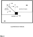
- FIG. 2 is a conceptual diagram illustrating an example technique for predicting a current video block 102 within a current picture 103 according to an intra BC mode.
- FIG. 2 illustrates a predictive video block 104 within current picture 103.
- a video coder e.g., video encoder 20 and/or video decoder 30, may use predictive video block 104 to predict current video block 102 according to an intra BC mode in accordance with the techniques of this disclosure.
- Video encoder 20 determines a predictive video block 104 for predicting current video block 102 from a set of previously reconstructed blocks of video data. That is, predictive video block 104 is determined from among the blocks of video data that were already encoded and reconstructed in the same frame as current video block 102. Video encoder 20 reconstructs blocks of video data by inverse quantizing and inverse transforming the video data that is also included in the encoded video bitstream, and summing the resulting residual blocks with the predictive blocks used to predict the reconstructed blocks of video data.
- search region 108 within current picture 103 which may also be referred to as an "intended area,” “search area,” or “raster area,” includes a set of previously reconstructed video blocks.
- Video encoder 20 may determine predictive video block 104 used to predict current video block 102 from among the video blocks in search region 108 based on an analysis of the relative efficiency and accuracy of predicting and coding current video block 102 based on various video blocks within search region 108.
- Video encoder 20 determines a two-dimensional block vector 106 (also called an offset vector, displacement vector, or motion vector) representing the location or displacement of predictive video block 104 relative to current video block 102.
- block vector 106 is calculated from the position of the upper left pixel of predictive video block 104 and the position of the upper left pixel of current video block 102.
- block vector 106 may be calculated relative to any predefined or signaled position within predictive video block 104 and current video block 102.
- Block vector 106 is a two-dimensional vector that includes a horizontal displacement component 112 (i.e., an x-component) and a vertical displacement component 110 (i.e., a y-component), which respectively represent the horizontal and vertical displacement of predictive video block 104 relative to current video block 102.
- Video encoder 20 may include one or more syntax elements that identify or define block vector 106, e.g., that define horizontal displacement component 112 and vertical displacement component 110, in the encoded video bitstream.
- Video decoder 30 may decode the one or more syntax elements to determine the horizontal and vertical displacement components of block vector 106, and use the determined block vector to identify predictive video block 104 for current video block 102.
- Current video block 102 may be a CU, or a PU of a CU.
- a video coder e.g., video encoder 20 and/or video decoder 30, may split a CU that is predicted according to intra BC into a number of PUs.
- the video coder may determine a respective (e.g., different) BVD for each of the PUs of the CU.
- a video coder may split a 2Nx2N CU into two 2NxN PUs, two Nx2N PUs, or four NxN PUs.
- a video coder may split a 2Nx2N CU into ((N/2)xN + (3N/2)xN) PUs, ((3N/2)xN + (N/2)xN) PUs, (Nx(N/2) + Nx(3N/2)) PUs, (Nx(3N/2) + Nx(N/2)) PUs, four (N/2)x2N PUs, or four 2Nx(N/2) PUs.
- video coder may predict a 2Nx2N CU using a 2Nx2N PU.
- BVD block vector difference
- BVP block vector predictor
- FIG. 3 is a conceptual diagram showing an example of BVD coding in accordance with examples of this disclosure.
- predictive blocks 204, 206, 208, and 214 are potential valid predictive blocks that may be used to code current block 202, and may be used to generate valid BVDs.
- Block 210 is not within search region 212, and as such may not be used as a predictive block (i.e., is an invalid predictive block, or be used to generate a BVD from any BVP.
- a BVD is a defined as a block vector (i.e., the vector from the current block to a predictive block) minus the BVP (e.g., defaults predictors P1-P3 in FIG. 3 ).
- a BVD may be comprised of both an x component (BVDx) and a y component (BVDy).
- BVPs P1, P2, and P3 are default BVPs used to decrease the size of the block vector that is signaled.
- Video encoder 20 may calculate the BVD relative to a BVP, rather than relative to the current block 202.
- Video encoder 20 may determine one of BVPs P1, P2, or P3 to use to calculate the BVD based on a predetermined rate-distortion criteria.
- video encode 20 may be configured to select the BVP that produces the smallest BVD in bits.
- Video encoder 20 may be configured to signal a syntax element indicating the BVP used to generate the BVD.
- Video decoder 30 is configured to decode the BVD and then add the value of the BVP to the decoded BVD to obtain the block vector for current block 202.
- BVPs P1, P2, and P3 are defined relative to the width (W) in pixels of current block 202.
- current block 202 is a PU and width W is the width of the PU.
- BVP P1 is at position (-2W, 0). That is, BVP P1 is two times the width of current block 202 to left of the upper left corner pixel of current block 202.
- the positions of the BVPs may be defined relative to any point in current block 202.
- BVP P2 is one times the width of current block 202 to the left of the upper left corner pixel of current block 202.
- BVP P3 is one times the width of current block 202 to the right of the upper left corner pixel of current block 202.
- BVPs P1, P2, and P3 are only examples of potential BVPs.
- Another BVP may be defined at position (W, 0) away from current block 202.
- two default BVPs are used (e.g., (-2W, 0) and (-W, 0) or (-2W, 0) and (2W, 0).
- a position within a neighboring block e.g., the upper left corner of a neighboring block
- FIG. 4 shows an example of where left neighboring block 222 and above neighboring block 220, relative to current block 202, may be used as BVPs.
- any predictive block for current block 202 must be within search region 212, as such, the BVDy component for a positive BVDx component greater than W must be at least one height in pixels higher than current block 202.
- BVPs P2 and P3 when a BVDx component calculated from BVPs P2 or P3 is greater than zero.
- video encoder 20 may be configured to not signal (e.g., conditionally signal) one or more of a sign or portion (e.g., BVD minus an offset) of a component of a BVD under certain conditions and/or given certain characteristics of the intra BC video coding process.
- video decoder 30 would be configured to infer the value of the sign or portion of a component of the BVD based on some predefined rules.
- BVD vector such as sign or BVD minus an offset
- intra BC coding prediction is performed relative to the decoded samples within the current picture contrary to a temporal picture that is already fully decoded in the case of motion vector decoding for inter-prediction.
- conditional signaling comprises determining whether or not to signal a particular syntax element representative of a BVD component value (e.g., sign of a BVD component or BVD minus an offset) based on one or more video coding characteristics.
- a particular syntax element representative of a BVD component value e.g., sign of a BVD component or BVD minus an offset
- video decoder 30 may be configured to infer the value of the syntax element based on the one or more video coding characteristics.
- Example video coding characteristics are detailed below, and may include one or more of the sign value of the x component of a BVD, the sign value of the y component of a BVD, the use of default predictors (e.g., BVPs P1, P2, and P3 of FIG. 3 ), a value of the BVP, a position of the BVP, an availability of a neighboring block of the currently encoded block, a coding mode of the neighboring block, and/or an intra BC merge index.
- default predictors e.g., BVPs P1, P2, and P3 of FIG. 3
- video encoder 20 may be configured to conditionally signal the sign value of a component of a BVD based on one or more video coding characteristics.
- video decoder 30 may be configured to infer the sign value for a component of a BVD based on one or more video coding characteristics.
- video encoder 20 may be configured to not signal the sign value of a BVD component, and video decoder 30 may be configured to infer the sign value of a BVD component, in the situation where the video coding characteristics are such that only one sign value is possible for a particular component of the BVD.
- video encoder 20 may be configured to conditionally signal the sign value of a component of a BVD based on the value and/or sign of the other component of the BVD. That is, video encoder 20 may be configured to conditionally signal the sign of BVDy based on the value and sign of BVDx or vice versa. In particular, video encoder 20 may be configured to not signal the sign value of a first component of a BVD when the other component of the BVD is such that the first component of the BVD must always have a specific value.
- BVDy is necessarily also positive because the predictive block must be in search region 212.
- video encoder 20 may be configured to not signal the sign of BVDy.
- video decoder 30 may be configured to infer the sign value of BVDy to be positive.
- video encoder 20 may be configured to conditionally signal the sign value of a component of a BVD based on whether default BVPs are used for intra BC coding.
- default BVPs P1, P2, and P3 may be defined as shown in FIG. 3 .
- one default BVP may be defined as having an x value as the right-most pixel of the picture.
- BVDx is necessarily always negative, and video encoder 20 may be configured to not signal the sign of BVDx.
- a default BVP may be defined as being the left-most pixel of picture. As such, if a BVP positioned at the left-most pixel of the picture were used, BVDx would necessarily always be positive, and video encoder 20 may be configured to not signal the sign of BVDx.
- video encoder 20 may be configured to conditionally signal the sign value of a component of a BVD based on the availability of neighboring blocks and/or the prediction mode of neighboring blocks (e.g., left neighboring block 222 and/or above neighboring block 220 of FIG. 4 ).
- neighboring blocks may be used as a BVP.
- video encoder 20 may signal the sign values of the BVD components (i.e., not inferred by video decoder 30), as the neighboring block used as the BVP may not be known at video decoder 30. If neighboring blocks are not available to be used as a BVP, sign values may be hidden according to other video coding characteristics, including any of the characteristics discussed above.
- video encoder 20 may be configured to conditionally signal the BVD minus a predetermined offset in situations where a component of the BVD is necessarily greater than a height or width of the current block. As discussed above, given the requirement that the predictive block be within search region 212, in some situations a component of the BVD will necessarily be greater than the width of height of current block 202. For example, referring back to FIG. 3 , if the BVDx component relative to BVP P1 is greater than W, the BVDy component must be greater than height of current block 202 to be in search region 212.
- video encoder 20 may be configured to signal BVDy minus an offset.
- the offset may be the height of current block 202 or a function of the height of current block 202 (e.g., the height plus some constant).
- Video decoder 30 may be configured to add the offset back to value of the BVDy component received in the encoded bitstream to recover the actual value of the BVDy component.
- any combination of video coding characteristics that indicate that a particular component of the BVD is greater than the offset in order for the predictive block to be within search region 212 may be used to determine when the component of the BVD is conditionally signaled as BVD minus the offset.
- example video coding characteristics may include one or more of the sign value of the x component of a BVD, the sign value of the y component of a BVD, the use of default predictors (e.g., BVPs P1, P2, and P3 of FIG. 3 ), a value of the BVP, a position of the BVP, an availability of a neighboring block of the currently encoded block, a coding mode of the neighboring block, and/or an intra BC merge index.
- default predictors e.g., BVPs P1, P2, and P3 of FIG. 3
- video decoder 30 may be configured to receive, in an encoded video bitstream, an encoded block of the video data encoded using an intra BC mode.
- Video decoder 30 may be configured to also receive one or more syntax elements that are indicative of a first absolute value of a first component of a BVD and receive one or more syntax elements that are indicative of a second absolute value of a second component of a BVD.
- Video decoder 30 may be configured to decode the first absolute value of the first component of the BVD associated with the encoded block of video data and decode a second absolute value of the second component of the associated with the encoded block of video data.
- Video decoder 30 may be further configured to receive a syntax element indicative of a first sign value for the first component of the BVD and decode the first sign value for the first component of the BVD.
- video decoder 30 may be configured to infer a second sign value for the second component of the BVD based on one or more video coding characteristics indicating that the second sign value is restricted to one value. That is, rather than receiving a syntax value for the sign value of the second component of the BVD (i.e., video encoder 20 does not encode a syntax element indicating the sign value of the second component), video decoder 30 infers the sign value of the second component.
- Video decoder 30 may be further configured to determine the BVD based on the decoded first absolute value of the first component of the BVD, the decoded second absolute value of the second component of the BVD, the decoded first sign value for the first component of the BVD, and the inferred second sign value for the second component of the BVD. Video decoder 30 may then determine a block vector from the BVD and a block vector predictor, and decode the block of video data using the block vector.
- the one or more video coding characteristics may include one or more of the first sign value of the first component of the BVD, use of default block vector predictors, a value of the block vector predictor, a position of the block vector predictor, an availability of a neighboring block to the encoded block, a coding mode of the neighboring block, or an intra BC merge index.
- the first component of the BVD is the x component of the BVD
- the second component of the BVD is the y component of the BVD.
- the first component of the BVD is the y component of the BVD
- the second component of the BVD is the x component of the BVD.
- video decoder 30 is configured to receive a first syntax element associated with the first absolute value of the first component of the BVD, and infer that a value of the first syntax element represents the first absolute value of the first component of the BVD minus an offset based on the one or more video coding characteristics indicating that the first absolute value of the first component is greater than the offset.
- Video decoder 30 may determine the first absolute value of the first component by adding the value of the first syntax element to the offset.
- the offset is one of a width of the encoded block of video data or a height of the encoded block of video data.
- the offset is a function of a width of the encoded block of video data or a function of a height of the encoded block of video data.
- intra_bc_bvd_sign_flag [compIdx] may specify the sign of a block vector component difference as follows. If intra_bc_bvd_sign_flag[compIdx] is equal to 0, the corresponding block vector component difference may have a positive value. Otherwise (intra_bc_bvd_sign_flag[compIdx] is equal to 1), the corresponding block vector component difference may have a negative value.
- syntax element IsAboveIBC 1 indicates the CU above to the current block is coded as intraBC mode, and the value of IsAboveIBC equal to 0 indicates the CU above to the current block is not coded as intraBC mode.
- syntax element iMVPIdx is the index of the intraBC merge candidate.
- the default BVPs may be (-2W,0) and (2W,0) or (-2W,0) and (-W,0).
- example the default BVP may be (-2W,0).
- the intra_bc_bvd_sign_flag is only inferred (e.g., hidden) in the case that neither of the neighboring blocks are coded using intraBC mode (i.e., uiBVPredType is 1 or 2).
- the default BVPs used are known by video decoder 30, and thus the value of intra_bc_bvd_sign_flag may be inferred given the presence of the example video coding characteristics shown above.
- the following is an example implementation of the conditional signaling and inference of the absolute value of the vertical component (i.e., the y component) of the BVD minus an offset.
- Location (0, 0) is equivalent to the upper left corner of the currently coded block, and as such, the use of (0, 0) indicate no prediction of the block vector.
- a flag was proposed to be added to specify whether the BV is predicted or not (i.e., predictor is zero or not). If not predicted, BV is coded without prediction. The flag was proposed to be signaled only when the BV component is non-zero.
- a context coded flag is coded to indicate the BVD is zero.
- another flag is coded to indicate if absolute level of the BVD is greater than N. If the absolute value of the BVD is greater than N, the remaining absolute level is coded using bypass Exp-Golomb codes with order k.
- One flag is coded to indicate sign of the BVD.
- this disclosure describes an example implementation for intra BC BVD coding when the predictor for intra block vector coding happens to be (0, 0) and the binarization scheme of JCTVC-R0181 is used. Note that the following techniques may be generalized for any other binarization scheme or BVPs.
- one aspect of the following example is to infer parts/components of the BVD, such as sign and offset, based on the unique geometry characteristics of intra BC coding.
- the prediction happens from the spatial decoded samples within the current picture contrary to a temporal picture that is already fully decoded in the case of inter motion vector decoding.
- bv_pred_flag specifies whether the block vector is predicted or not. When bv_pred_flag is equal to 1, the block vector is not predicted, else it is predicted. When bc_bv_pred_flag is not present, it is inferred to be equal to 0.
- syntax element bvd_sign_flag [compIdx] specifies the sign of a block vector component difference as follows:
- the following is another example proposed implementation for intra BC BVD coding.
- the following example implementation is based on proposals from C. Pang, et al., "Description of Core Experiment 1 (CE1): Vector entropy coding” Test 1.1 and Test 4.1, Joint Collaborative Team on Video Coding (JCT-VC) of ITU-T SG 16 WP 3 and ISO/IEC JTC 1/SC 29/WG 11, 18th Meeting: Sapporo, JP, 30 June - 9 July 2014 (JCTVC- R1101 Test 4.1 and JCTVC-R1101 Test 1.1), and X.
- CE1 Core Experiment 1
- JCT-VC Joint Collaborative Team on Video Coding
- JCTVC-R1101 test 4.1 proposes to code sign of both the block vector components (BVDx and BVDy) jointly using a truncated unary code when the block vector is not predicted.
- Table 3 shows example unary codes for coding the sign of BVDx and BVDy when the block vector is not predicted.
- Table 3 - BVD Unary Code Example 1 BVDx's sign BVDy's sign Code negative negative 1 negative positive 00 Positive negative 01
- this disclosure proposes the following implementation.
- the techniques below are generally based on the techniques of the disclosure described above and may be used in conjunction with any other technique described in this disclosure.
- syntax element bv_pred_flag specifies whether the block vector is predicted or not. When bv_pred_flag is equal to 0, the block vector is not predicted, else when bv_pred_flag is 1, the block vector is predicted. When bv_pred_flag is not present, it is inferred to be equal to 1.
- sytnax element bvd_sign_flag [compIdx] specifies the sign of a block vector component difference as follows:
- video decoder 30 may be configured to infer the second sign value for the second component (e.g., the sign value of the y component) in the case that a syntax element indicating the second sign value is not present in the encoded video bitstream.
- the second sign value for the second component e.g., the sign value of the y component
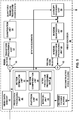
- FIG. 5 is a block diagram illustrating an example video encoder 20 that may implement the intra BC BVD coding techniques described in this disclosure.
- Video encoder 20 may perform intra and inter coding of video blocks within video slices.
- Intra coding relies on spatial prediction to reduce or remove spatial redundancy in video within a given video frame or picture.
- Inter coding relies on temporal prediction to reduce or remove temporal redundancy in video within adjacent frames or pictures of a video sequence.
- Intra mode may refer to any of several spatial based compression modes.
- video encoder 20 includes video data memory 40, prediction processing unit 41, decoded picture buffer 64, summer 50, transform processing unit 52, quantization unit 54, and entropy encoding unit 56.
- Prediction processing unit 41 includes partition unit 35, motion estimation unit 42, motion compensation unit 44, intra BC unit 48, and intra prediction processing unit 46.
- video encoder 20 also includes inverse quantization unit 58, inverse transform processing unit 60, and summer 62.
- An in-loop filter (not pictured) may be positioned between summer 62 and decoded picture buffer 64.
- Intra prediction processing unit 46 within prediction processing unit 41 may perform intra predictive coding of the current video block relative to one or more neighboring blocks in the same frame or slice as the current block to be coded to provide spatial compression.
- Motion estimation unit 42 and motion compensation unit 44 within prediction processing unit 41 perform inter predictive coding of the current video block relative to one or more predictive blocks in one or more reference pictures to provide temporal compression.
- Motion estimation unit 42 may be configured to determine the inter prediction mode for a video slice according to a predetermined pattern for a video sequence.
- the predetermined pattern may designate video slices in the sequence as P slices or B slices.
- Motion estimation unit 42 and motion compensation unit 44 may be highly integrated, but are illustrated separately for conceptual purposes.
- Motion estimation, performed by motion estimation unit 42 is the process of generating motion vectors, which estimate motion for video blocks.
- a motion vector for example, may indicate the displacement of a PU of a video block within a current video frame or picture relative to a predictive block within a reference picture.
- a predictive block is a block that is found to closely match the PU of the video block to be coded in terms of pixel difference, which may be determined by sum of absolute difference (SAD), sum of square difference (SSD), or other difference metrics.
- video encoder 20 may calculate values for sub-integer pixel positions of reference pictures stored in decoded picture buffer 64. For example, video encoder 20 may interpolate values of one-quarter pixel positions, one-eighth pixel positions, or other fractional pixel positions of the reference picture. Therefore, motion estimation unit 42 may perform a motion search relative to the full pixel positions and fractional pixel positions and output a motion vector with fractional pixel precision.
- Motion estimation unit 42 calculates a motion vector for a PU of a video block in an inter coded slice by comparing the position of the PU to the position of a predictive block of a reference picture.
- the reference picture may be selected from a first reference picture list (List 0) or a second reference picture list (List 1), each of which identify one or more reference pictures stored in decoded picture buffer 64.
- Motion estimation unit 42 sends the calculated motion vector to entropy encoding unit 56 and motion compensation unit 44.
- intra BC unit 48 may generate vectors and fetch predictive blocks in a manner similar to that described above with respect to motion estimation unit 42 and motion compensation unit 44, but with the predictive blocks being in the same picture or frame as the current block and with the vectors being referred to as block vectors as opposed to motion vectors.
- intra BC unit 48 may use motion estimation unit 42 and motion compensation unit 44, in whole or in part, to perform such functions for Intra BC prediction according to the techniques described herein.
- a predictive block may be a block that is found to closely match the block to be coded, in terms of pixel difference, which may be determined by sum of absolute difference (SAD), sum of squared difference (SSD), or other difference metrics, and identification of the block may include calculation of values for sub-integer pixel positions.
- SAD sum of absolute difference
- SSD sum of squared difference
- identification of the block may include calculation of values for sub-integer pixel positions.
- Motion compensation performed by motion compensation unit 44, may involve fetching or generating the predictive block based on the motion vector determined by motion estimation, possibly performing interpolations to sub-pixel precision.
- motion compensation unit 44 may locate the predictive block to which the motion vector points in one of the reference picture lists.
- Video encoder 20 forms a residual video block by subtracting pixel values of the predictive block from the pixel values of the current video block being coded, forming pixel difference values.
- the pixel difference values form residual data for the block, and may include both luma and chroma difference components.
- Summer 50 represents the component or components that perform this subtraction operation.
- Motion compensation unit 44 may also generate syntax elements associated with the video blocks and the video slice for use by video decoder 30 in decoding the video blocks of the video slice.
- video encoder 20 may form a residual video block by subtracting pixel values of the predictive block from the pixel values of the current video block being coded, forming pixel difference values.
- the pixel difference values form residual data for the block, and may include both luma component differences and chroma component differences.
- Summer 50 represents the component or components that perform this subtraction operation.
- Intra BC unit 48 and/or motion compensation unit 44 may also generate syntax elements associated with the video blocks and the video slice for use by a video decoder, such as video decoder 30, in decoding the video blocks of the video slice.
- the syntax elements may include, for example, syntax elements defining the vector used to identify the predictive block, any flags indicating the prediction mode, or any other syntax described with respect to the techniques of this disclosure.
- Intra prediction processing unit 46 may intra-predict a current block, as an alternative to the inter-prediction performed by motion estimation unit 42 and motion compensation unit 44, or the Intra BC prediction performed by intra BC unit 48, as described above.
- intra prediction processing unit 46 may determine an intra prediction mode, including an Intra BC mode, to use to encode a current block.
- intra prediction processing unit 46 may encode a current block using various intra prediction modes, e.g., during separate encoding passes, and intra prediction processing unit 46 (or a mode select unit, in some examples) may select an appropriate intra prediction mode to use from the tested modes.
- intra prediction processing unit 46 may calculate rate-distortion values using a rate-distortion analysis for the various tested intra prediction modes, and select the intra prediction mode having the best rate-distortion characteristics among the tested modes.
- Rate-distortion analysis generally determines an amount of distortion (or error) between an encoded block and an original, unencoded block that was encoded to produce the encoded block, as well as a bit rate (that is, a number of bits) used to produce the encoded block.
- Intra prediction processing unit 46 may calculate ratios from the distortions and rates for the various encoded blocks to determine which intra prediction mode exhibits the best rate-distortion value for the block.
- intra prediction processing unit 46 may provide information indicative of the selected intra prediction mode for the block to entropy encoding unit 56.
- Entropy encoding unit 56 may encode the information indicating the selected intra prediction mode in accordance with the techniques of this disclosure.
- Video encoder 20 may include in the transmitted bitstream configuration data, which may include a plurality of intra prediction mode index tables and a plurality of modified intra prediction mode index tables (also referred to as codeword mapping tables), definitions of encoding contexts for various blocks, and indications of a most probable intra prediction mode, an intra prediction mode index table, and a modified intra prediction mode index table to use for each of the contexts.
- video encoder 20 forms a residual video block by subtracting the predictive block from the current video block.
- the residual video data in the residual block may be included in one or more TUs and applied to transform processing unit 52.
- Transform processing unit 52 transforms the residual video data into residual transform coefficients using a transform, such as a discrete cosine transform (DCT) or a conceptually similar transform.
- Transform processing unit 52 may convert the residual video data from a pixel domain to a transform domain, such as a frequency domain.
- DCT discrete cosine transform
- Transform processing unit 52 may send the resulting transform coefficients to quantization unit 54.
- Quantization unit 54 quantizes the transform coefficients to further reduce bit rate. The quantization process may reduce the bit depth associated with some or all of the coefficients. The degree of quantization may be modified by adjusting a quantization parameter.
- quantization unit 54 may then perform a scan of the matrix including the quantized transform coefficients. Alternatively, entropy encoding unit 56 may perform the scan.
- Inverse quantization unit 58 and inverse transform processing unit 60 apply inverse quantization and inverse transformation, respectively, to reconstruct the residual block in the pixel domain for later use as a reference block for prediction of other video blocks.
- Motion compensation unit 44 and/or intra BC unit 48 may calculate a reference block by adding the residual block to a predictive block of one of the reference pictures within one of the reference picture lists.
- Motion compensation unit 44 and/or intra BC unit 48 may also apply one or more interpolation filters to the reconstructed residual block to calculate sub-integer pixel values for use in motion estimation.
- Summer 62 adds the reconstructed residual block to the motion compensated prediction block produced by motion compensation unit 44 to produce a reference block for storage in decoded picture buffer 64.
- the reference block may be used by intra BC unit 48, motion estimation unit 42 and motion compensation unit 44 as a reference block to inter predict a block in a subsequent video frame or picture.
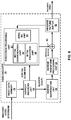
- FIG. 6 is a block diagram illustrating an example video decoder 30 that may implement the techniques for coding BVDs in intra BC mode described in this disclosure.
- video decoder 30 includes video data memory 79, entropy decoding unit 80, prediction processing unit 81, inverse quantization unit 86, inverse transformation processing unit 88, summer 90, and decoded picture buffer 92.
- Prediction processing unit 81 includes intra BC unit 85, motion compensation unit 82 and intra prediction processing unit 84.
- Video decoder 30 may, in some examples, perform a decoding pass generally reciprocal to the encoding pass described with respect to video encoder 20 from FIG. 5 .
- a unit of video decoder 30 may be tasked to perform the techniques of this disclosure.
- the techniques of this disclosure may be divided among one or more of the units of video decoder 30.
- intra BC unit 85 may perform the techniques of this disclosure, alone, or in combination with other units of video decoder 30, such as motion compensation unit 82, intra prediction processing unit 84, and entropy decoding unit 80.
- video decoder 30 may not include intra BC unit 85 and the functionality of intra BC unit 85 may be performed by other components of prediction processing unit 81, such as motion compensation unit 82.
- Video data memory 79 may store video data, such as an encoded video bitstream, to be decoded by the components of video decoder 30.
- the video data stored in video data memory 79 may be obtained, for example, from storage device 32, from a local video source, such as a camera, via wired or wireless network communication of video data, or by accessing physical data storage media.
- Video data memory 79 may form a coded picture buffer (CPB) that stores encoded video data from an encoded video bitstream.
- Decoded picture buffer 92 is one example of a decoded picture buffer (DPB) that stores reference video data for use in decoding video data by video decoder 30 (e.g., in intra or inter coding modes, also referred to as intra or inter prediction coding modes).
- DPB decoded picture buffer
- Video data memory 79 and DPB 92 may be formed by any of a variety of memory devices, such as dynamic random access memory (DRAM), including synchronous DRAM (SDRAM), magnetoresistive RAM (MRAM), resistive RAM (RRAM), or other types of memory devices.
- Video data memory 79 and DPB 92 may be provided by the same memory device or separate memory devices.
- video data memory 79 may be on-chip with other components of video decoder 30, or off-chip relative to those components.
- video decoder 30 receives an encoded video bitstream that represents video blocks of an encoded video slice and associated syntax elements from video encoder 20.
- Entropy decoding unit 80 of video decoder 30 entropy decodes the bitstream to generate quantized coefficients, motion vectors, and other syntax elements.
- Entropy decoding unit 80 forwards the motion vectors and other syntax elements to prediction processing unit 81.
- Video decoder 30 may receive the syntax elements at the video slice level and/or the video block level.
- intra prediction processing unit 84 of prediction processing unit 81 may generate prediction data for a video block of the current video slice based on a signaled intra prediction mode and data from previously decoded blocks of the current frame or picture. Prediction processing unit 81 may be configured to implement the techniques of this disclosure for coding BVDs in intra BC coding mode.
- motion compensation unit 82 of prediction processing unit 81 produces predictive blocks for a video block of the current video slice based on the motion vectors and other syntax elements received from entropy decoding unit 80. The predictive blocks may be produced from one of the reference pictures within one of the reference picture lists.
- Video decoder 30 may construct the reference frame lists, List 0 and List 1, using default construction techniques based on reference pictures stored in decoded picture buffer 92.
- intra BC unit 85 of prediction processing unit 81 produces predictive blocks for the current video block based on block vectors and other syntax elements received from entropy decoding unit 80.
- the predictive blocks may be within a reconstructed region within the same picture as the current video block defined by video encoder 20, and retrieved from DPB 92.
- Motion compensation unit 82 and/or intra BC unit 85 may determine prediction information for a video block of the current video slice by parsing the motion vectors and other syntax elements, and uses the prediction information to produce the predictive blocks for the current video block being decoded. For example, motion compensation unit 82 uses some of the received syntax elements to determine a prediction mode (e.g., intra or inter prediction) used to code the video blocks of the video slice, an inter prediction slice type (e.g., B slice or P slice), construction information for one or more of the reference picture lists for the slice, motion vectors for each inter encoded video block of the slice, inter prediction status for each inter coded video block of the slice, and other information to decode the video blocks in the current video slice.
- a prediction mode e.g., intra or inter prediction
- an inter prediction slice type e.g., B slice or P slice
- construction information for one or more of the reference picture lists for the slice motion vectors for each inter encoded video block of the slice, inter prediction status for each inter coded video block of the slice
- intra BC unit 85 may use some of the received syntax elements, e.g., a flag, to determine that the current video block was predicted using the Intra BC mode, construction information indicating which video blocks of the picture are within the reconstructed region and should be stored in DPB 92, block vectors for each Intra BC predicted video block of the slice, Intra BC prediction status for each Intra BC predicted video block of the slice, and other information to decode the video blocks in the current video slice.
- a flag e.g., a flag
- Motion compensation unit 82 may also perform interpolation based on interpolation filters. Motion compensation unit 82 may use interpolation filters as used by video encoder 20 during encoding of the video blocks to calculate interpolated values for sub-integer pixels of reference blocks. In this case, motion compensation unit 82 may determine the interpolation filters used by video encoder 20 from the received syntax elements and use the interpolation filters to produce predictive blocks.
- intra BC unit 48 may be configured to encode a first absolute value of a first component of a BVD associated with a block of video data encoded with intra BC mode (702) and encode a second absolute value of a second component of the associated with the block of video data (704).
- Intra BC unit may be further configured to encode a first sign value for the first component of the BVD (706), and not encode a second sign value for the second component of the BVD based on one or more video coding characteristics indicating that the second sign value is restricted to one value (708).
- Intra BC unit 48 may be further configured to generate syntax elements for the first absolute value, the second absolute value, and the first sign value (710).
- the one or more video coding characteristics may include one or more of the first sign value of the first component of the BVD, use of default block vector predictors, a value of the block vector predictor, a position of the block vector predictor, an availability of a neighboring block to the encoded block, a coding mode of the neighboring block, or an intra BC merge index.
- FIG. 9 is a flowchart illustrating another example decoding method of the disclosure.
- the techniques of FIG. 9 may be implemented by one or more hardware units of video decoder 30, including intra BC unit 85.
- intra BC unit 85 is configured to receive a first syntax element associated with the first absolute value of the first component of the BVD (902), and infer that a value of the first syntax element represents the first absolute value of the first component of the BVD minus an offset based on the one or more video coding characteristics indicating that the first absolute value of the first component is greater than the offset (904).
- Intra BC unit 85 may determine the first absolute value of the first component by adding the value of the first syntax element to the offset (906).
- the offset is one of a width of the encoded block of video data or a height of the encoded block of video data.
- the offset is a function of a width of the encoded block of video data or a function of a height of the encoded block of video data.
- Disk and disc includes compact disc (CD), laser disc, optical disc, digital versatile disc (DVD), floppy disk and Blu-ray disc, where disks usually reproduce data magnetically, while discs reproduce data optically with lasers. Combinations of the above should also be included within the scope of computer-readable media.
- processors such as one or more digital signal processors (DSPs), general purpose microprocessors, application specific integrated circuits (ASICs), field programmable logic arrays (FPGAs), or other equivalent integrated or discrete logic circuitry.
- DSPs digital signal processors
- ASICs application specific integrated circuits
- FPGAs field programmable logic arrays
- processors may refer to any of the foregoing structure or any other structure suitable for implementation of the techniques described herein.
- the functionality described herein may be provided within dedicated hardware and/or software modules configured for encoding and decoding, or incorporated in a combined codec. Also, the techniques could be fully implemented in one or more circuits or logic elements.
- the techniques of this disclosure may be implemented in a wide variety of devices or apparatuses, including a wireless handset, an integrated circuit (IC) or a set of ICs (e.g., a chip set).
- IC integrated circuit
- a set of ICs e.g., a chip set.
- Various components, modules, or units are described in this disclosure to emphasize functional aspects of devices configured to perform the disclosed techniques, but do not necessarily require realization by different hardware units. Rather, as described above, various units may be combined in a codec hardware unit or provided by a collection of interoperative hardware units, including one or more processors as described above, in conjunction with suitable software and/or firmware.
Landscapes
- Engineering & Computer Science (AREA)
- Multimedia (AREA)
- Signal Processing (AREA)
- Compression Or Coding Systems Of Tv Signals (AREA)
Claims (15)
- Verfahren zum Decodieren von Videodaten, wobei das Verfahren Folgendes beinhaltet:Empfangen, in einem encodierten Videobitstrom, eines encodierten Blocks von Videodaten, die mit einem BC-(Block Copy)-Modus encodiert wurden;Decodieren eines ersten absoluten Wertes einer ersten Komponente einer Blockvektordifferenz BVD, die mit dem encodierten Block von Videodaten assoziiert ist;Decodieren eines zweiten absoluten Wertes einer zweiten Komponente der mit dem encodierten Block von Videodaten assoziierten BVD;Decodieren eines ersten Vorzeichenwertes für die erste Komponente der BVD;gekennzeichnet durch:Inferieren, wenn ein zweiter Vorzeichenwert für die zweite Komponente der BVD nicht in dem Bitstrom encodiert ist, des zweiten Vorzeichenwertes für die zweite Komponente der BVD so, dass der zum Erzeugen der BVD benutzte prädiktive Block innerhalb einer Suchregion liegt, die einen Satz von Videoblöcken umfasst, die dem aktuellen Block als prädiktive Videoblöcke zur Verfügung stehen, wobei das Inferieren auf der Position eines vorbestimmten Blockvektorprädiktors BVP, dem ersten absoluten Wert der ersten Komponente der BVD und dem Vorzeichen der ersten Komponente der BVD basiert;Bestimmen der BVD auf der Basis des decodierten ersten absoluten Wertes der ersten Komponente der BVD, des decodierten zweiten absoluten Wertes der zweiten Komponente der BVD, dem decodierten ersten Vorzeichenwert für die erste Komponente der BVD und dem inferierten zweiten Vorzeichenwert für die zweite Komponente der BVD;Bestimmen eines Blockvektors von der BVD und dem vorbestimmten BVP; undDecodieren des Blocks von Videodaten anhand des Blockvektors.
- Verfahren nach Anspruch 1, wobei die erste Komponente der BVD die x-Komponente der BVD ist und wobei die zweite Komponente der BVD die y-Komponente der BVD ist und wobei das Inferieren des zweiten Vorzeichenwertes für die zweite Komponente das Inferieren des zweiten Vorzeichenwertes der y-Komponente der BVD in dem Fall beinhaltet, in dem die BVD prädiziert ist und ein absoluter Wert der x-Komponente größer als null ist.
- Verfahren nach Anspruch 1, wobei die erste Komponente der BVD die y-Komponente der BVD ist und wobei die zweite Komponente der BVD die x-Komponente der BVD ist und wobei das Inferieren des zweiten Vorzeichenwertes für die zweite Komponente das Inferieren des zweiten Vorzeichenwertes der x-Komponente der BVD in dem Fall beinhaltet, in dem die BVD prädiziert ist und ein absoluter Wert der y-Komponente größer als null ist.
- Verfahren nach Anspruch 1, wobei das Decodieren des ersten absoluten Wertes der ersten Komponente der BVD Folgendes beinhaltet:Empfangen eines mit dem ersten absoluten Wert der ersten Komponente der BVD assoziierten ersten Syntaxelements;Inferieren, dass ein Wert des ersten Syntaxelements den ersten absoluten Wert der ersten Komponente der BVD minus einem Versatz repräsentiert, auf der Basis der ein oder mehreren Videocodierungscharakteristiken, die anzeigen, dass der erste absolute Wert der ersten Komponente größer ist als der Versatz; undBestimmen des ersten absoluten Wertes der ersten Komponente durch Addieren des Wertes des ersten Syntaxelements zu dem Versatz.
- Verfahren nach Anspruch 4, wobei der Versatz eine Breite des encodierten Blocks von Videodaten oder eine Höhe des encodierten Blocks von Videodaten ist.
- Verfahren nach Anspruch 4, wobei der Satz eine Funktion einer Breite des encodierten Blocks von Videodaten oder eine Funktion einer Höhe des encodierten Blocks von Videodaten ist.
- Vorrichtung, konfiguriert zum Decodieren von Videodaten, wobei die Vorrichtung Folgendes umfasst:Mittel zum Empfangen, in einem encodierten Videobitstrom, eines encodierten Blocks von Videodaten, die mit einem Intra-BC-(Block Copy)-Modus encodiert wurden;Mittel zum Decodieren eines ersten absoluten Wertes einer ersten Komponente einer mit dem encodierten Block von Videodaten assoziierten Blockvektordifferenz (BVD);Mittel zum Decodieren eines zweiten absoluten Wertes einer zweiten Komponente der mit dem encodierten Block von Videodaten assoziierten BVD;Mittel zum Decodieren eines ersten Vorzeichenwertes für die erste Komponente der BVD;gekennzeichnet durch:Mittel zum Inferieren eines zweiten Vorzeichenwertes für die zweite Komponente der BVD, wenn der zweite Vorzeichenwert der BVD in dem empfangenen Bitstrom nicht encodiert ist, konfiguriert zum Inferieren des zweiten Vorzeichenwertes für die zweite Komponente der BVD so, dass der zum Erzeugen der BVD benutzte prädiktive Block innerhalb einer Suchregion liegt, die einen Satz von Videoblöcken umfasst, die dem aktuellen Block als prädiktive Blöcke zur Verfügung stehen, wobei das Inferieren auf einer Position eines vorbestimmten Blockvektorprädiktors BVP, dem absoluten Wert der ersten Komponente der BVD und dem Vorzeichen der ersten Komponente der BVD basiert;Mittel zum Bestimmen der BVD auf der Basis des decodierten ersten absoluten Wertes der ersten Komponente der BVD, des decodierten zweiten absoluten Wertes der zweiten Komponente der BVD, des decodierten ersten Vorzeichenwertes für die erste Komponente der BVD und des inferierten zweiten Vorzeichenwertes für die zweite Komponente der BVD;Mittel zum Bestimmen eines Blockvektors von der BVD und dem vorbestimmten Blockvektorprädiktor; undMittel zum Decodieren des Blocks von Videodaten anhand des Blockvektors.
- Vorrichtung nach Anspruch 7, wobei das Mittel zum Decodieren des ersten absoluten Wertes der ersten Komponente der BVD Folgendes umfasst:Mittel zum Empfangen eines mit dem ersten absoluten Wert der ersten Komponente der BVD assoziierten ersten Syntaxelements;Mittel zum Inferieren, dass ein Wert des ersten Syntaxelements den ersten absoluten Wert der ersten Komponente der BVD minus einem Versatz repräsentiert, auf der Basis der ein oder mehreren Videocodierungscharakteristiken, die anzeigen, dass der erste absolute Wert der ersten Komponente größer ist als der Versatz; undMittel zum Bestimmen des ersten absoluten Wertes der ersten Komponente durch Addieren des Wertes des ersten Syntaxelements zu dem Versatz.
- Vorrichtung nach Anspruch 7, wobei die erste Komponente der BVD die x-Komponente der BVD ist, wobei die zweite Komponente der BVD die y-Komponente der BVD ist und wobei zum Inferieren des zweiten Vorzeichenwertes für die zweite Komponente der Video-Decoder zum Inferieren des zweiten Vorzeichenwertes der y-Komponente der BVD in dem Fall konfiguriert ist, dass die BVD prädiziert und ein absoluter Wert der x-Komponente größer als null ist.
- Vorrichtung nach Anspruch 7, wobei die erste Komponente der BVD die y-Komponente der BVD ist, wobei die zweite Komponente der BVD die x-Komponente der BVD ist und wobei zum Inferieren des zweiten Vorzeichenwertes für die zweite Komponente der Video-Decoder zum Inferieren des zweiten Vorzeichenwertes der x-Komponente der BVD in dem Fall konfiguriert ist, dass die BVD prädiziert und ein absoluter Wert der y-Komponente größer als null ist.
- Vorrichtung nach Anspruch 7, wobei zum Decodieren des ersten absoluten Wertes der ersten Komponente der BVD der Video-Decoder konfiguriert ist zum:Empfangen eines mit dem ersten absoluten Wert der ersten Komponente der BVD assoziierten ersten Syntaxelements;Inferieren, dass ein Wert des ersten Syntaxelements den ersten absoluten Wert der ersten Komponente der BVD minus einem Versatz repräsentiert, basierend auf den ein oder mehreren Videocodierungscharakteristiken, die anzeigen, dass der erste absolute Wert der ersten Komponente größer ist als der Versatz; undBestimmen des ersten absoluten Wertes der ersten Komponente durch Addieren des Wertes des ersten Syntaxelements zu dem Versatz.
- Vorrichtung nach Anspruch 11, wobei der Versatz eine Funktion einer Breite des encodierten Blocks von Videodaten oder eine Funktion einer Höhe des encodierten Blocks von Videodaten ist.
- Verfahren zum Encodieren von Videodaten, wobei das Verfahren Folgendes beinhaltet:Encodieren eines ersten absoluten Wertes einer ersten Komponente einer Blockvektordifferenz BVD, assoziiert mit einem aktuellen Block von Videodaten, der mit Intra-BC-(Block Copy)-Modus encodiert ist, wobei die BVD ein Vektor von einem Blockvektorprädiktor BVP (P1, P2, P3, 220, 222) zu einem prädiktiven Block (204, 206, 208, 214) für den aktuellen Block (202) ist;Encodieren eines zweiten absoluten Wertes einer zweiten Komponente der mit dem aktuellen Block von Videodaten assoziierten BVD;Encodieren eines ersten Vorzeichenwertes für die erste Komponente der BVD;Erzeugen von Syntaxelementen für den ersten absoluten Wert, den zweiten absoluten Wert und den ersten Vorzeichenwert,gekennzeichnet durch:Feststellen, wenn benachbarte Blöcke des aktuellen Blocks nicht für die Verwendung als BVP zur Verfügung stehen, ob ein zweiter Vorzeichenwert für die zweite Komponente einer vorbestimmten BVD auf einen Wert beschränkt ist, wobei das Bestimmen die Verwendung einer Position des vorbestimmten BVP, des ersten absoluten Wertes der ersten Komponente der BVD und des Vorzeichens der ersten Komponente der BVD beinhaltet, um festzustellen, ob der zum Erzeugen der BVD benutzte prädiktive Block innerhalb einer Suchregion liegt, die einen Satz von Videoblöcken umfasst, die dem aktuellen Block als prädiktive Blöcke zur Verfügung stehen;Nichtencodieren, wenn ein zweiter Vorzeichenwert für die zweite Komponente der BVD als auf einen Wert beschränkt festgestellt wird, eines zweiten Vorzeichenwertes für die zweite Komponente der BVD; andernfallsEncodieren des zweiten Vorzeichenwertes für die zweite Komponente der BVD.
- Verfahren nach Anspruch 13, wobei das Encodieren des ersten absoluten Wertes der ersten Komponente der BVD Folgendes beinhaltet:
Subtrahieren eines Versatzes von dem ersten absoluten Wert auf der Basis der ein oder mehreren Videocodierungscharakteristiken, die anzeigen, dass der erste absolute Wert der ersten Komponente größer ist als der Versatz. - Verfahren nach einem der Ansprüche 1 bis 6, 13 oder 14, wobei das Verfahren auf einem drahtlosen Kommunikationsgerät durchgeführt werden kann, wobei das drahtlose Kommunikationsgerät Folgendes umfasst:ein Datenspeichermedium, konfiguriert zum Speichern des encodierten Blocks von Videodaten;einen Prozessor, konfiguriert zum Ausführen von Befehlen zum Verarbeiten des Blocks von Videodaten, die in dem Datenspeichermedium gespeichert sind; undeinen Empfänger zum Empfangen des Blocks von Videodaten.
Applications Claiming Priority (5)
| Application Number | Priority Date | Filing Date | Title |
|---|---|---|---|
| US201462015313P | 2014-06-20 | 2014-06-20 | |
| US201462053672P | 2014-09-22 | 2014-09-22 | |
| US201462056965P | 2014-09-29 | 2014-09-29 | |
| US14/743,564 US9948949B2 (en) | 2014-06-20 | 2015-06-18 | Intra block copy block vector signaling for video coding |
| PCT/US2015/036718 WO2015196087A1 (en) | 2014-06-20 | 2015-06-19 | Intra block copy block vector signaling for video coding |
Publications (2)
| Publication Number | Publication Date |
|---|---|
| EP3158750A1 EP3158750A1 (de) | 2017-04-26 |
| EP3158750B1 true EP3158750B1 (de) | 2019-07-31 |
Family
ID=54870873
Family Applications (1)
| Application Number | Title | Priority Date | Filing Date |
|---|---|---|---|
| EP15734769.1A Active EP3158750B1 (de) | 2014-06-20 | 2015-06-19 | Intrablockkopie-blockvektorsignalisierung zur videokodierung |
Country Status (5)
| Country | Link |
|---|---|
| US (1) | US9948949B2 (de) |
| EP (1) | EP3158750B1 (de) |
| JP (1) | JP2017519447A (de) |
| CN (1) | CN106464904A (de) |
| WO (1) | WO2015196087A1 (de) |
Families Citing this family (37)
| Publication number | Priority date | Publication date | Assignee | Title |
|---|---|---|---|---|
| MX2016004705A (es) | 2013-10-14 | 2016-07-18 | Microsoft Technology Licensing Llc | Caracteristicas del modo de prediccion copia de bloque interno para codificacion y decodificacion de imagen y video. |
| US11109036B2 (en) | 2013-10-14 | 2021-08-31 | Microsoft Technology Licensing, Llc | Encoder-side options for intra block copy prediction mode for video and image coding |
| WO2015100726A1 (en) * | 2014-01-03 | 2015-07-09 | Microsoft Corporation | Block vector prediction in video and image coding/decoding |
| US11284103B2 (en) | 2014-01-17 | 2022-03-22 | Microsoft Technology Licensing, Llc | Intra block copy prediction with asymmetric partitions and encoder-side search patterns, search ranges and approaches to partitioning |
| CN105493505B (zh) | 2014-06-19 | 2019-08-06 | 微软技术许可有限责任公司 | 统一的帧内块复制和帧间预测模式 |
| KR101748620B1 (ko) * | 2014-06-20 | 2017-07-04 | 성균관대학교산학협력단 | 영상의 부호화/복호화 방법 및 이를 이용하는 장치 |
| WO2015194913A1 (ko) * | 2014-06-20 | 2015-12-23 | 성균관대학교 산학협력단 | 영상의 부호화/복호화 방법 및 이를 이용하는 장치 |
| EP3202150B1 (de) | 2014-09-30 | 2021-07-21 | Microsoft Technology Licensing, LLC | Regeln für innerbildliche vorhersagemodi bei aktivierter wellenfrontparallelverarbeitung |
| GB2531003A (en) * | 2014-10-06 | 2016-04-13 | Canon Kk | Method and apparatus for vector encoding in video coding and decoding |
| US10701391B2 (en) * | 2017-03-23 | 2020-06-30 | Qualcomm Incorporated | Motion vector difference (MVD) prediction |
| WO2019239790A1 (ja) * | 2018-06-11 | 2019-12-19 | パナソニック インテレクチュアル プロパティ コーポレーション オブ アメリカ | 符号化装置、復号装置、符号化方法および復号方法 |
| US11317099B2 (en) * | 2018-10-05 | 2022-04-26 | Tencent America LLC | Method and apparatus for signaling an offset in video coding for intra block copy and/or inter prediction |
| US10951895B2 (en) | 2018-12-31 | 2021-03-16 | Alibaba Group Holding Limited | Context model selection based on coding unit characteristics |
| WO2020141831A2 (ko) * | 2018-12-31 | 2020-07-09 | 엘지전자 주식회사 | 인트라 블록 카피 예측을 이용한 영상 코딩 방법 및 장치 |
| KR20210118400A (ko) | 2019-02-01 | 2021-09-30 | 베이징 바이트댄스 네트워크 테크놀로지 컴퍼니, 리미티드 | 비디오 코딩을 위한 루마 종속적 크로마 잔차 스케일링의 구성 |
| CN113475079A (zh) * | 2019-02-01 | 2021-10-01 | 北京字节跳动网络技术有限公司 | 环路整形和帧内块复制之间的相互作用 |
| MX2021008963A (es) | 2019-02-02 | 2021-08-24 | Beijing Bytedance Network Tech Co Ltd | Manejo de bufer para copia intra-bloque en codificacion de video. |
| CN113366846A (zh) * | 2019-02-02 | 2021-09-07 | 北京字节跳动网络技术有限公司 | 用于视频编解码中的帧内块复制的缓冲区更新 |
| EP3915265A4 (de) | 2019-03-01 | 2022-06-22 | Beijing Bytedance Network Technology Co., Ltd. | Richtungsbasierte vorhersage für intrablockkopie in der videocodierung |
| EP3915252A4 (de) | 2019-03-04 | 2022-03-23 | Beijing Bytedance Network Technology Co., Ltd. | Implementierung von aspekten in einer intrablockkopie in der videocodierung |
| US11012686B2 (en) * | 2019-03-08 | 2021-05-18 | Tencent America LLC | Unified block vector prediction for intra picture block compensation |
| CN117499644A (zh) | 2019-03-14 | 2024-02-02 | 北京字节跳动网络技术有限公司 | 环路整形信息的信令和语法 |
| WO2020192614A1 (en) | 2019-03-23 | 2020-10-01 | Beijing Bytedance Network Technology Co., Ltd. | Restrictions on adaptive-loop filtering parameter sets |
| JP7332721B2 (ja) * | 2019-05-25 | 2023-08-23 | 北京字節跳動網絡技術有限公司 | イントラブロックコピー符号化ブロックにおけるブロックベクトルの符号化 |
| JP2022539468A (ja) | 2019-07-06 | 2022-09-09 | 北京字節跳動網絡技術有限公司 | 映像符号化におけるイントラブロックコピーのための仮想予測バッファ |
| CN114175633B (zh) | 2019-07-10 | 2023-12-29 | 北京字节跳动网络技术有限公司 | 用于视频编解码中的帧内块复制的样点标识 |
| KR20220030957A (ko) | 2019-07-11 | 2022-03-11 | 베이징 바이트댄스 네트워크 테크놀로지 컴퍼니, 리미티드 | 비디오 코딩에서 인트라 블록 카피를 위한 비트스트림 적합 제약 |
| US11653001B2 (en) * | 2020-09-11 | 2023-05-16 | Ofinno, Llc | Intra block copy |
| US20230095946A1 (en) * | 2021-09-28 | 2023-03-30 | Ofinno, Llc | Block Vector Difference Signaling for Intra Block Copy |
| US20230224457A1 (en) * | 2022-01-10 | 2023-07-13 | Comcast Cable Communications, Llc | Determination of Block Vector Predictor Candidate List |
| WO2023179676A1 (en) * | 2022-03-23 | 2023-09-28 | Beijing Bytedance Network Technology Co., Ltd. | Method, apparatus, and medium for video processing |
| WO2023193724A1 (en) * | 2022-04-05 | 2023-10-12 | Beijing Bytedance Network Technology Co., Ltd. | Method, apparatus, and medium for video processing |
| US20240048718A1 (en) * | 2022-08-08 | 2024-02-08 | Comcast Cable Communications, Llc | Magnitude Coding and Decoding Using Prediction |
| CA3209998A1 (en) * | 2022-08-22 | 2024-02-22 | Comcast Cable Communications, Llc | Magnitude prediction with candidate pruning |
| WO2024081315A1 (en) * | 2022-10-11 | 2024-04-18 | Comcast Cable Communications, Llc | Block vector difference (bvd) indication with reduced overhead |
| WO2024077572A1 (zh) * | 2022-10-13 | 2024-04-18 | Oppo广东移动通信有限公司 | 编解码方法、编码器、解码器以及存储介质 |
| EP4358510A1 (de) * | 2022-10-21 | 2024-04-24 | Comcast Cable Communications LLC | Blockvektordifferenz(bvd)-kodierung |
Family Cites Families (8)
| Publication number | Priority date | Publication date | Assignee | Title |
|---|---|---|---|---|
| US10536701B2 (en) * | 2011-07-01 | 2020-01-14 | Qualcomm Incorporated | Video coding using adaptive motion vector resolution |
| WO2013139250A1 (en) | 2012-03-22 | 2013-09-26 | Mediatek Inc. | Method and apparatus of scalable video coding |
| US20150071357A1 (en) | 2013-09-12 | 2015-03-12 | Qualcomm Incorporated | Partial intra block copying for video coding |
| AU2013228045A1 (en) * | 2013-09-13 | 2015-04-02 | Canon Kabushiki Kaisha | Method, apparatus and system for encoding and decoding video data |
| MX2016004705A (es) * | 2013-10-14 | 2016-07-18 | Microsoft Technology Licensing Llc | Caracteristicas del modo de prediccion copia de bloque interno para codificacion y decodificacion de imagen y video. |
| WO2015100726A1 (en) * | 2014-01-03 | 2015-07-09 | Microsoft Corporation | Block vector prediction in video and image coding/decoding |
| US9900625B2 (en) * | 2014-03-17 | 2018-02-20 | Mediatek Inc. | Method and apparatus for efficient information coding |
| JP6256222B2 (ja) * | 2014-06-19 | 2018-01-10 | 三菱電機株式会社 | 端末装置及びデータ管理装置 |
-
2015
- 2015-06-18 US US14/743,564 patent/US9948949B2/en active Active
- 2015-06-19 CN CN201580032642.2A patent/CN106464904A/zh active Pending
- 2015-06-19 JP JP2016573848A patent/JP2017519447A/ja not_active Ceased
- 2015-06-19 WO PCT/US2015/036718 patent/WO2015196087A1/en active Application Filing
- 2015-06-19 EP EP15734769.1A patent/EP3158750B1/de active Active
Non-Patent Citations (1)
| Title |
|---|
| None * |
Also Published As
| Publication number | Publication date |
|---|---|
| US9948949B2 (en) | 2018-04-17 |
| US20150373370A1 (en) | 2015-12-24 |
| EP3158750A1 (de) | 2017-04-26 |
| JP2017519447A (ja) | 2017-07-13 |
| CN106464904A (zh) | 2017-02-22 |
| WO2015196087A1 (en) | 2015-12-23 |
Similar Documents
| Publication | Publication Date | Title |
|---|---|---|
| EP3158750B1 (de) | Intrablockkopie-blockvektorsignalisierung zur videokodierung | |
| US10506228B2 (en) | Variable number of intra modes for video coding | |
| RU2697744C2 (ru) | Объединенное предсказание межкадровое и с внутрикадровой копией блока | |
| US9883197B2 (en) | Intra prediction of chroma blocks using the same vector | |
| KR102232099B1 (ko) | 변위 벡터들을 이용한 예측 블록으로부터의 인트라 예측 | |
| US9930341B2 (en) | Block vector coding for intra block copying | |
| US9332257B2 (en) | Coded black flag coding for 4:2:2 sample format in video coding | |
| US9736489B2 (en) | Motion vector determination for video coding | |
| US9451277B2 (en) | Restriction of prediction units in B slices to uni-directional inter prediction | |
| JP6231109B2 (ja) | コンテキスト適応型、マルチレベル有意性コーディングに関するコンテキスト導出 | |
| JP2021530906A (ja) | 広角イントラ予測を伴う位置依存イントラ予測組み合わせ | |
| US9854234B2 (en) | Reference picture status for video coding | |
| CN111373752A (zh) | 用于在视频译码中自适应的环路滤波的线路缓冲减少 | |
| US20140198855A1 (en) | Square block prediction | |
| EP3207706A1 (de) | Amvp und ableitung einer zusammenführungskandidatenliste für intrarundfunk- und interprädiktionsvereinigung | |
| CN112514386B (zh) | 网格编解码量化系数编解码 | |
| WO2015031806A1 (en) | Constrained intra prediction in video coding | |
| JP2018507616A (ja) | 予測ユニットの柔軟な区分化 | |
| US20130070848A1 (en) | Line buffer reduction for short distance intra-prediction | |
| KR20160031496A (ko) | 인트라 모션 보상 확장 | |
| EP2832094A1 (de) | Fusionssignalisierung und schleifenfilter mit ein-/aussignalisierung | |
| US20130188716A1 (en) | Temporal motion vector predictor candidate | |
| US20130195189A1 (en) | Implicit derivation of parallel motion estimation range size | |
| CN112673636A (zh) | 将运动向量四舍五入以自适应运动向量差分辨率及提高视频译码中的运动向量存储精度 | |
| CN115176472A (zh) | 用于合并估计区域的基于历史的运动向量预测约束 |
Legal Events
| Date | Code | Title | Description |
|---|---|---|---|
| STAA | Information on the status of an ep patent application or granted ep patent |
Free format text: STATUS: THE INTERNATIONAL PUBLICATION HAS BEEN MADE |
|
| PUAI | Public reference made under article 153(3) epc to a published international application that has entered the european phase |
Free format text: ORIGINAL CODE: 0009012 |
|
| STAA | Information on the status of an ep patent application or granted ep patent |
Free format text: STATUS: REQUEST FOR EXAMINATION WAS MADE |
|
| 17P | Request for examination filed |
Effective date: 20161130 |
|
| AK | Designated contracting states |
Kind code of ref document: A1 Designated state(s): AL AT BE BG CH CY CZ DE DK EE ES FI FR GB GR HR HU IE IS IT LI LT LU LV MC MK MT NL NO PL PT RO RS SE SI SK SM TR |
|
| AX | Request for extension of the european patent |
Extension state: BA ME |
|
| DAV | Request for validation of the european patent (deleted) | ||
| DAX | Request for extension of the european patent (deleted) | ||
| STAA | Information on the status of an ep patent application or granted ep patent |
Free format text: STATUS: EXAMINATION IS IN PROGRESS |
|
| 17Q | First examination report despatched |
Effective date: 20181130 |
|
| GRAP | Despatch of communication of intention to grant a patent |
Free format text: ORIGINAL CODE: EPIDOSNIGR1 |
|
| STAA | Information on the status of an ep patent application or granted ep patent |
Free format text: STATUS: GRANT OF PATENT IS INTENDED |
|
| INTG | Intention to grant announced |
Effective date: 20190228 |
|
| GRAS | Grant fee paid |
Free format text: ORIGINAL CODE: EPIDOSNIGR3 |
|
| GRAA | (expected) grant |
Free format text: ORIGINAL CODE: 0009210 |
|
| STAA | Information on the status of an ep patent application or granted ep patent |
Free format text: STATUS: THE PATENT HAS BEEN GRANTED |
|
| AK | Designated contracting states |
Kind code of ref document: B1 Designated state(s): AL AT BE BG CH CY CZ DE DK EE ES FI FR GB GR HR HU IE IS IT LI LT LU LV MC MK MT NL NO PL PT RO RS SE SI SK SM TR |
|
| REG | Reference to a national code |
Ref country code: CH Ref legal event code: EP Ref country code: GB Ref legal event code: FG4D |
|
| REG | Reference to a national code |
Ref country code: DE Ref legal event code: R096 Ref document number: 602015034797 Country of ref document: DE |
|
| REG | Reference to a national code |
Ref country code: AT Ref legal event code: REF Ref document number: 1162268 Country of ref document: AT Kind code of ref document: T Effective date: 20190815 |
|
| REG | Reference to a national code |
Ref country code: IE Ref legal event code: FG4D |
|
| REG | Reference to a national code |
Ref country code: NL Ref legal event code: MP Effective date: 20190731 |
|
| REG | Reference to a national code |
Ref country code: LT Ref legal event code: MG4D |
|
| REG | Reference to a national code |
Ref country code: AT Ref legal event code: MK05 Ref document number: 1162268 Country of ref document: AT Kind code of ref document: T Effective date: 20190731 |
|
| PG25 | Lapsed in a contracting state [announced via postgrant information from national office to epo] |
Ref country code: LT Free format text: LAPSE BECAUSE OF FAILURE TO SUBMIT A TRANSLATION OF THE DESCRIPTION OR TO PAY THE FEE WITHIN THE PRESCRIBED TIME-LIMIT Effective date: 20190731 Ref country code: FI Free format text: LAPSE BECAUSE OF FAILURE TO SUBMIT A TRANSLATION OF THE DESCRIPTION OR TO PAY THE FEE WITHIN THE PRESCRIBED TIME-LIMIT Effective date: 20190731 Ref country code: NL Free format text: LAPSE BECAUSE OF FAILURE TO SUBMIT A TRANSLATION OF THE DESCRIPTION OR TO PAY THE FEE WITHIN THE PRESCRIBED TIME-LIMIT Effective date: 20190731 Ref country code: BG Free format text: LAPSE BECAUSE OF FAILURE TO SUBMIT A TRANSLATION OF THE DESCRIPTION OR TO PAY THE FEE WITHIN THE PRESCRIBED TIME-LIMIT Effective date: 20191031 Ref country code: NO Free format text: LAPSE BECAUSE OF FAILURE TO SUBMIT A TRANSLATION OF THE DESCRIPTION OR TO PAY THE FEE WITHIN THE PRESCRIBED TIME-LIMIT Effective date: 20191031 Ref country code: AT Free format text: LAPSE BECAUSE OF FAILURE TO SUBMIT A TRANSLATION OF THE DESCRIPTION OR TO PAY THE FEE WITHIN THE PRESCRIBED TIME-LIMIT Effective date: 20190731 Ref country code: PT Free format text: LAPSE BECAUSE OF FAILURE TO SUBMIT A TRANSLATION OF THE DESCRIPTION OR TO PAY THE FEE WITHIN THE PRESCRIBED TIME-LIMIT Effective date: 20191202 Ref country code: SE Free format text: LAPSE BECAUSE OF FAILURE TO SUBMIT A TRANSLATION OF THE DESCRIPTION OR TO PAY THE FEE WITHIN THE PRESCRIBED TIME-LIMIT Effective date: 20190731 Ref country code: HR Free format text: LAPSE BECAUSE OF FAILURE TO SUBMIT A TRANSLATION OF THE DESCRIPTION OR TO PAY THE FEE WITHIN THE PRESCRIBED TIME-LIMIT Effective date: 20190731 |
|
| PG25 | Lapsed in a contracting state [announced via postgrant information from national office to epo] |
Ref country code: LV Free format text: LAPSE BECAUSE OF FAILURE TO SUBMIT A TRANSLATION OF THE DESCRIPTION OR TO PAY THE FEE WITHIN THE PRESCRIBED TIME-LIMIT Effective date: 20190731 Ref country code: IS Free format text: LAPSE BECAUSE OF FAILURE TO SUBMIT A TRANSLATION OF THE DESCRIPTION OR TO PAY THE FEE WITHIN THE PRESCRIBED TIME-LIMIT Effective date: 20191130 Ref country code: RS Free format text: LAPSE BECAUSE OF FAILURE TO SUBMIT A TRANSLATION OF THE DESCRIPTION OR TO PAY THE FEE WITHIN THE PRESCRIBED TIME-LIMIT Effective date: 20190731 Ref country code: GR Free format text: LAPSE BECAUSE OF FAILURE TO SUBMIT A TRANSLATION OF THE DESCRIPTION OR TO PAY THE FEE WITHIN THE PRESCRIBED TIME-LIMIT Effective date: 20191101 Ref country code: AL Free format text: LAPSE BECAUSE OF FAILURE TO SUBMIT A TRANSLATION OF THE DESCRIPTION OR TO PAY THE FEE WITHIN THE PRESCRIBED TIME-LIMIT Effective date: 20190731 Ref country code: ES Free format text: LAPSE BECAUSE OF FAILURE TO SUBMIT A TRANSLATION OF THE DESCRIPTION OR TO PAY THE FEE WITHIN THE PRESCRIBED TIME-LIMIT Effective date: 20190731 |
|
| PG25 | Lapsed in a contracting state [announced via postgrant information from national office to epo] |
Ref country code: TR Free format text: LAPSE BECAUSE OF FAILURE TO SUBMIT A TRANSLATION OF THE DESCRIPTION OR TO PAY THE FEE WITHIN THE PRESCRIBED TIME-LIMIT Effective date: 20190731 |
|
| PG25 | Lapsed in a contracting state [announced via postgrant information from national office to epo] |
Ref country code: DK Free format text: LAPSE BECAUSE OF FAILURE TO SUBMIT A TRANSLATION OF THE DESCRIPTION OR TO PAY THE FEE WITHIN THE PRESCRIBED TIME-LIMIT Effective date: 20190731 Ref country code: EE Free format text: LAPSE BECAUSE OF FAILURE TO SUBMIT A TRANSLATION OF THE DESCRIPTION OR TO PAY THE FEE WITHIN THE PRESCRIBED TIME-LIMIT Effective date: 20190731 Ref country code: PL Free format text: LAPSE BECAUSE OF FAILURE TO SUBMIT A TRANSLATION OF THE DESCRIPTION OR TO PAY THE FEE WITHIN THE PRESCRIBED TIME-LIMIT Effective date: 20190731 Ref country code: IT Free format text: LAPSE BECAUSE OF FAILURE TO SUBMIT A TRANSLATION OF THE DESCRIPTION OR TO PAY THE FEE WITHIN THE PRESCRIBED TIME-LIMIT Effective date: 20190731 Ref country code: RO Free format text: LAPSE BECAUSE OF FAILURE TO SUBMIT A TRANSLATION OF THE DESCRIPTION OR TO PAY THE FEE WITHIN THE PRESCRIBED TIME-LIMIT Effective date: 20190731 |
|
| PG25 | Lapsed in a contracting state [announced via postgrant information from national office to epo] |
Ref country code: SM Free format text: LAPSE BECAUSE OF FAILURE TO SUBMIT A TRANSLATION OF THE DESCRIPTION OR TO PAY THE FEE WITHIN THE PRESCRIBED TIME-LIMIT Effective date: 20190731 Ref country code: CZ Free format text: LAPSE BECAUSE OF FAILURE TO SUBMIT A TRANSLATION OF THE DESCRIPTION OR TO PAY THE FEE WITHIN THE PRESCRIBED TIME-LIMIT Effective date: 20190731 Ref country code: IS Free format text: LAPSE BECAUSE OF FAILURE TO SUBMIT A TRANSLATION OF THE DESCRIPTION OR TO PAY THE FEE WITHIN THE PRESCRIBED TIME-LIMIT Effective date: 20200224 Ref country code: SK Free format text: LAPSE BECAUSE OF FAILURE TO SUBMIT A TRANSLATION OF THE DESCRIPTION OR TO PAY THE FEE WITHIN THE PRESCRIBED TIME-LIMIT Effective date: 20190731 |
|
| REG | Reference to a national code |
Ref country code: DE Ref legal event code: R097 Ref document number: 602015034797 Country of ref document: DE |
|
| PLBE | No opposition filed within time limit |
Free format text: ORIGINAL CODE: 0009261 |
|
| STAA | Information on the status of an ep patent application or granted ep patent |
Free format text: STATUS: NO OPPOSITION FILED WITHIN TIME LIMIT |
|
| PG2D | Information on lapse in contracting state deleted |
Ref country code: IS |
|
| PG25 | Lapsed in a contracting state [announced via postgrant information from national office to epo] |
Ref country code: IS Free format text: LAPSE BECAUSE OF FAILURE TO SUBMIT A TRANSLATION OF THE DESCRIPTION OR TO PAY THE FEE WITHIN THE PRESCRIBED TIME-LIMIT Effective date: 20191030 |
|
| 26N | No opposition filed |
Effective date: 20200603 |
|
| PG25 | Lapsed in a contracting state [announced via postgrant information from national office to epo] |
Ref country code: SI Free format text: LAPSE BECAUSE OF FAILURE TO SUBMIT A TRANSLATION OF THE DESCRIPTION OR TO PAY THE FEE WITHIN THE PRESCRIBED TIME-LIMIT Effective date: 20190731 |
|
| PG25 | Lapsed in a contracting state [announced via postgrant information from national office to epo] |
Ref country code: MC Free format text: LAPSE BECAUSE OF FAILURE TO SUBMIT A TRANSLATION OF THE DESCRIPTION OR TO PAY THE FEE WITHIN THE PRESCRIBED TIME-LIMIT Effective date: 20190731 |
|
| REG | Reference to a national code |
Ref country code: CH Ref legal event code: PL |
|
| PG25 | Lapsed in a contracting state [announced via postgrant information from national office to epo] |
Ref country code: LU Free format text: LAPSE BECAUSE OF NON-PAYMENT OF DUE FEES Effective date: 20200619 |
|
| REG | Reference to a national code |
Ref country code: BE Ref legal event code: MM Effective date: 20200630 |
|
| PG25 | Lapsed in a contracting state [announced via postgrant information from national office to epo] |
Ref country code: LI Free format text: LAPSE BECAUSE OF NON-PAYMENT OF DUE FEES Effective date: 20200630 Ref country code: CH Free format text: LAPSE BECAUSE OF NON-PAYMENT OF DUE FEES Effective date: 20200630 Ref country code: IE Free format text: LAPSE BECAUSE OF NON-PAYMENT OF DUE FEES Effective date: 20200619 |
|
| PG25 | Lapsed in a contracting state [announced via postgrant information from national office to epo] |
Ref country code: BE Free format text: LAPSE BECAUSE OF NON-PAYMENT OF DUE FEES Effective date: 20200630 |
|
| PG25 | Lapsed in a contracting state [announced via postgrant information from national office to epo] |
Ref country code: MT Free format text: LAPSE BECAUSE OF FAILURE TO SUBMIT A TRANSLATION OF THE DESCRIPTION OR TO PAY THE FEE WITHIN THE PRESCRIBED TIME-LIMIT Effective date: 20190731 Ref country code: CY Free format text: LAPSE BECAUSE OF FAILURE TO SUBMIT A TRANSLATION OF THE DESCRIPTION OR TO PAY THE FEE WITHIN THE PRESCRIBED TIME-LIMIT Effective date: 20190731 |
|
| PG25 | Lapsed in a contracting state [announced via postgrant information from national office to epo] |
Ref country code: MK Free format text: LAPSE BECAUSE OF FAILURE TO SUBMIT A TRANSLATION OF THE DESCRIPTION OR TO PAY THE FEE WITHIN THE PRESCRIBED TIME-LIMIT Effective date: 20190731 |
|
| PGFP | Annual fee paid to national office [announced via postgrant information from national office to epo] |
Ref country code: FR Payment date: 20230509 Year of fee payment: 9 Ref country code: DE Payment date: 20230509 Year of fee payment: 9 |
|
| PGFP | Annual fee paid to national office [announced via postgrant information from national office to epo] |
Ref country code: GB Payment date: 20230510 Year of fee payment: 9 |