EP3158308B1 - Verbessertes systems zur prüfung der düse einer raumfahrt motor - Google Patents
Verbessertes systems zur prüfung der düse einer raumfahrt motor Download PDFInfo
- Publication number
- EP3158308B1 EP3158308B1 EP15733823.7A EP15733823A EP3158308B1 EP 3158308 B1 EP3158308 B1 EP 3158308B1 EP 15733823 A EP15733823 A EP 15733823A EP 3158308 B1 EP3158308 B1 EP 3158308B1
- Authority
- EP
- European Patent Office
- Prior art keywords
- divergent
- actuators
- divergent section
- assembly
- forces
- Prior art date
- Legal status (The legal status is an assumption and is not a legal conclusion. Google has not performed a legal analysis and makes no representation as to the accuracy of the status listed.)
- Active
Links
Images


Classifications
-
- G—PHYSICS
- G01—MEASURING; TESTING
- G01M—TESTING STATIC OR DYNAMIC BALANCE OF MACHINES OR STRUCTURES; TESTING OF STRUCTURES OR APPARATUS, NOT OTHERWISE PROVIDED FOR
- G01M15/00—Testing of engines
- G01M15/14—Testing gas-turbine engines or jet-propulsion engines
-
- F—MECHANICAL ENGINEERING; LIGHTING; HEATING; WEAPONS; BLASTING
- F02—COMBUSTION ENGINES; HOT-GAS OR COMBUSTION-PRODUCT ENGINE PLANTS
- F02K—JET-PROPULSION PLANTS
- F02K9/00—Rocket-engine plants, i.e. plants carrying both fuel and oxidant therefor; Control thereof
- F02K9/96—Rocket-engine plants, i.e. plants carrying both fuel and oxidant therefor; Control thereof characterised by specially adapted arrangements for testing or measuring
-
- F—MECHANICAL ENGINEERING; LIGHTING; HEATING; WEAPONS; BLASTING
- F02—COMBUSTION ENGINES; HOT-GAS OR COMBUSTION-PRODUCT ENGINE PLANTS
- F02K—JET-PROPULSION PLANTS
- F02K9/00—Rocket-engine plants, i.e. plants carrying both fuel and oxidant therefor; Control thereof
- F02K9/97—Rocket nozzles
-
- F—MECHANICAL ENGINEERING; LIGHTING; HEATING; WEAPONS; BLASTING
- F05—INDEXING SCHEMES RELATING TO ENGINES OR PUMPS IN VARIOUS SUBCLASSES OF CLASSES F01-F04
- F05D—INDEXING SCHEME FOR ASPECTS RELATING TO NON-POSITIVE-DISPLACEMENT MACHINES OR ENGINES, GAS-TURBINES OR JET-PROPULSION PLANTS
- F05D2260/00—Function
- F05D2260/12—Testing on a test bench
Definitions
- the present invention relates to the field of test benches for diverging spacecraft engines.
- Tests on the diverging spacecraft engines for the simulation of flight conditions are necessary in order to guarantee the good behavior of the diverging ones during their use.
- the ground tests do not make it possible to reproduce all the conditions of use during the flight of the spacecraft, which differ greatly from conventional aircraft, and therefore require either specific tests or numerical simulations perfectly representative Numerical simulations of this type are very restrictive and require theoretical modeling and considerable efforts.
- the simulations carried out on the engines to measure the thrust aim to immobilize the divergent in order to keep the engine aligned in an axial direction, and are therefore content to keep it in position without applying localized stresses so as to simulate the flight conditions.
- the behavior of the divergent in flight is therefore not taken into account; only the axial thrust of the motor is studied.
- the present invention thus aims to at least partially remedy this problem.
- the present invention provides a system comprising a test bench for diverging spacecraft engine and an assembly comprising a diverging spacecraft engine, Said assembly comprising a proximal end and a distal end, the test bench comprising a chassis provided with means for fixing the proximal end of the assembly comprising the divergent part to the chassis, the assembly being characterized in that the test bench comprises actuators adapted to locally apply forces on the divergent, said efforts simulating flight conditions of the divergent.
- the actuators are typically adapted to locally apply stresses in a head section of the divergent, said head section of the divergent being adjacent to the distal end.
- the actuators include for example jacks adapted to exert a tensile force on the divergent via cables.
- the actuators then typically comprise angle references disposed between the diverging part and the jacks, so that the cables are oriented perpendicular to the surface of application of the stresses.
- the actuators comprise cylinders adapted to exert a compressive force on the divergent via rigid rods.
- the assembly typically comprises at least a pair of actuators arranged on either side of a divergent axis, adapted to apply symmetrical stresses with respect to said axis.
- the actuators are arranged so as to apply asymmetrical forces with respect to an axis of the assembly comprising the divergent.
- the actuators can also be arranged so as to apply forces in an axial direction of the assembly comprising the divergent.
- the invention also relates to a method for testing an assembly comprising a divergent by means of a system as presented above, in which said assembly comprises a combustion chamber, said test method being carried out while the combustion chamber is Operating. As a variant, said test method is carried out while the combustion chamber is stopped.
- the Figures 1A and 1B present two views of a system according to one aspect of the invention.
- the system presented comprises a test bench 1 and an assembly comprising a diverging spacecraft engine.
- the assembly comprising a divergent comprises a divergent 2 having a proximal end 21 and a distal end 22, and a combustion chamber 4 having a proximal end 41 and a distal end 22.
- the distal end 22 corresponds to the free end of the divergent when it is mounted on a spacecraft engine, while the proximal end 21 of the divergent 2 is the end of the divergent 2 connected to the combustion chamber 4
- the combustion chamber 4 also has a proximal end 41, and a distal end 42 by which it is connected to the proximal end 21 of the divergent 2.
- the divergent 2 extends along an axis ZZ, and typically has a symmetry of revolution around this axis.
- a head section of the divergent 2, adjacent to the distal end 22 of the divergent 2 corresponding for example to 20% of the divergent, measured from the distal end 22 along the axis ZZ, or even 2% of the divergent, measured from the distal end 22 along the axis ZZ.
- the test bench 1 comprises a fixed frame 11, provided with fastening means 12 adapted to engage the proximal end of the assembly comprising a diverging part, that is to say in the example presented, the proximal end 41 of the combustion chamber 4.
- the proximal end 21 of the divergent 2 can be engaged by the fixing means 12, in the case where the assembly comprising the divergent 2 does not include the combustion chamber 4.
- the fixing means 12 can be of various types, and for example immobilize the assembly comprising the divergent 2 relative to the chassis 11, or allow one or more degrees of freedom of the assembly comprising the diverging 2 relative to the chassis 11, for example one or more degrees of freedom in rotation.
- the test bench 3 also includes actuators 3, adapted to locally apply forces to the divergent 2.
- the actuators 3 are typically configured so as to exert a compressive force or a tensile force on the divergent 2.
- the actuators 3 typically comprise one or more pairs of actuators configured so as to apply forces symmetrical with respect to the axis ZZ of the divergent 2, or forces that are not symmetrical with respect to the axis ZZ of the divergent 2, the configuration of the forces dependent on the loads that one wishes to simulate.
- the actuators 3 comprise a pair of two actuators 3a and 3b, arranged symmetrically with respect to the axis ZZ of the divergent 2.
- actuators 3a and 3b each comprise a jack, respectively 31a and 31b, associated with a cable, respectively 32a and 32b, for exerting a tensile force on the divergent tending to its ovalization.
- the jacks 31a and 31b are mounted on the chassis 11 of the test bench 1, substantially at the level of a stress application section on the divergent 2.
- the forces applied by the actuators 3 are calculated so as to simulate flight conditions of the divergent, and in particular the different stresses to which the divergent 2 is subjected during the different phases of a spacecraft flight, under different flight phases.
- the actuators 3 may include other elements making it possible to apply mechanical loads, and are not limited to jacks.
- the actuators 3, and in particular the means for applying the forces, here the jacks 31, are controlled in terms of force, and not in terms of displacement. Thus, any vibrations, expansions and clearances of the system do not affect the stresses applied.
- the actuators 3 comprise a set of pulleys producing angle references 33, which makes it possible to orient the cables 32 relative to the jacks 31 of the actuators 3 and relative to the divergent 2, and therefore allows a greater latitude for the positioning of the jacks 31, while making it possible to modify the bending moment, the axial thrust and the circumferential forces applied to the divergent by modifying the position of the angular references 33.
- the actuators 3 comprise two pairs of actuators: two actuators 3a and 3b arranged parallel to the axis ZZ, and two actuators 3c and 3d arranged parallel to the axis ZZ. These different actuators 3a to 3d are typically offset by 90 ° around the axis ZZ.
- the use of several pairs of actuators makes it possible to apply forces in different directions, and is therefore not limited to a single direction of ovalization as is the case in the embodiments presented on the Figures 1A, 1B, 2A and 2B .
- the different actuators, and in particular the actuators of the same torque are not necessarily arranged parallel to the axis ZZ.
- Other configurations are possible, with any number of actuators, regularly or not distributed around the divergent 2.
- a non-symmetrical application of the forces can for example experimentally simulate the effect of a pressure asymmetry at the bottom of the divergent 2.
- FIG. 3B an example of ovalization is shown in which only the actuators 3a and 3b apply a force to the divergent; the ovalization obtained is therefore similar to that shown on the Figures 1A and 1B .
- the actuators 3 in addition to an ovalization, also apply a bending moment and a compressive force to the divergent 2, simulating for example its thrust.
- the different actuators each comprise a beam or a structure 34 to which the cable 32 is fixed, typically in the middle of the beam 34.
- the beam 34 comprises two connecting cables 321 and 322, typically connected at its two opposite ends, and each connected to the divergent 2.
- Each of the actuators 3a, 3b, 3c and 3d is thus connected to the divergent 2 by two contact points via the connection cables.
- the cables 32 and connecting cables 321 and 322 for applying the forces on the divergent are not not perpendicular to the axis ZZ of the divergent 2, which makes it possible to modify the bending moment, the axial thrust and the circumferential force applied to the divergent 2 as indicated previously.
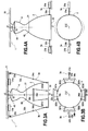
- FIGS 4A and 4B present another variant of the embodiment presented on the Figures 1A and 1B , in which the cables 32 are replaced by rigid rods 35 actuated by the jacks 31.
- the actuators 3a and 3b therefore apply here a compressive force on the divergent 2, and no longer in traction as was the case in the previous figures.
- the ovalization takes place in a direction perpendicular to that observed in the embodiments of the Figures 1A and 1B .
- the Figures 5A and 5B are another variant of the embodiment presented on the Figures 4A and 4B , comprising two pairs of actuators offset by 90 °; a first pair of actuators 3a and 3b, and a second pair of actuators 3c and 3d.
- the actuators 3 here also include rigid rods adapted to apply a compressive force to the divergent 2.
- the rods 35 include one end forming a fork 36 having two branches bearing against the divergent 2.
- Each of the actuators 3a, 3b, 3c and 3d is thus in contact with the divergent 2 via the two branches of its fork 36.
- an example of ovalization is shown in which only the actuators 3c and 3d apply a force to the divergent.
- the figure 3C one can in particular vary the direction of this ovalization by applying forces via the other pair of actuators 3a and 3b.
- rods 35 make it possible to apply compressive forces to the divergent 2; the rods 35 can then simply come to bear against the divergent 2. It is also possible to connect the rods 35 to the divergent 2 via connections which furthermore make it possible to apply tensile forces to the divergent, for example by means of ball-joint or linear annular connections.
- the system presented thus makes it possible, by means of different actuators, to simulate the stresses to which a divergent spacecraft engine is subjected during a flight, in an experimental manner, without requiring substantial modeling efforts and while keeping a limited cost.
- the proposed system also allows significant latitude in the application of forces, either in terms of points of application or in terms of means of application of these forces. Symmetrical or asymmetrical forces can thus be applied, in different zones of the divergence 2. Forces having variable frequencies can also be applied. Several types of force can also be applied simultaneously, to simulate the different conditions of use. Axial forces can also be applied to the divergent, in particular simulating the thrust in a vacuum during operation.
- the proposed system also makes it possible to carry out tests up to the rupture of the diverging part 2, for example buckling or plastic instability tests, without this causing the loss of other elements as would be the case for a test of a complete spacecraft. Furthermore, the proposed system can be used in a controlled atmosphere, in particular under vacuum, in order to reproduce certain conditions of use of the divergent 2.
- the system also makes it possible to simulate conditions of use of a divergent 2, and therefore to analyze the impact of deformations or manufacturing defects on the behavior of the divergent at these conditions of use.
- the deformations can then for example be carried out before the installation of the assembly comprising the divergent 2 on the test bench 1, or be carried out by suitable actuators 3.
- the proposed system can be applied to the diverging rocket engines with liquid or powder propellants, to the diverging engines of lower or upper stages of space launchers, to the metallic or composite diverging, to the cooled or uncooled diverging.
Landscapes
- Engineering & Computer Science (AREA)
- Chemical & Material Sciences (AREA)
- Combustion & Propulsion (AREA)
- Mechanical Engineering (AREA)
- General Engineering & Computer Science (AREA)
- Physics & Mathematics (AREA)
- General Physics & Mathematics (AREA)
- Aerodynamic Tests, Hydrodynamic Tests, Wind Tunnels, And Water Tanks (AREA)
- Investigating Strength Of Materials By Application Of Mechanical Stress (AREA)
- Testing Of Engines (AREA)
Claims (10)
- System, umfassend einen Prüfstand (1) und eine Anordnung (2, 4), die eine Expansionsdüse (2) für einen Raumfahrzeugmotor umfasst,
wobei die die Expansionsdüse aufweisende Anordnung ein proximales Ende (41) und ein distales Ende (22) umfasst,
wobei der Prüfstand (1) einen Rahmen (11) umfasst, der mit Mitteln zum Befestigen (12) des proximalen Endes (41) der die Expansionsdüse (2) umfassenden Anordnung an dem Rahmen (11) versehen ist,
wobei die Anordnung dadurch gekennzeichnet ist, dass der Prüfstand (1) Aktuatoren (3) umfasst, die geeignet sind, Kräfte lokal auf die Expansionsdüse (2) aufzubringen, wobei die Kräfte die Flugbedingungen der Expansionsdüse (2) simulieren. - System gemäß Anspruch 1, wobei die Aktuatoren (3) geeignet sind, Kräfte lokal in einem Kopfabschnitt der Expansionsdüse (2) aufzubringen, wobei der Kopfabschnitt der Expansionsdüse (2) an das distale Ende (22) der Anordnung angrenzt.
- System gemäß einem der Ansprüche 1 oder 2, wobei die Aktuatoren (3) Zylinder (31) umfassen, die geeignet sind, über Kabel (32) eine Zugkraft auf die Expansionsdüse (2) auszuüben.
- System gemäß Anspruch 3, wobei die Aktuatoren (3) Winkelgetriebe (33) umfassen, die zwischen der Expansionsdüse (2) und den Zylindern (31) angeordnet sind, sodass die Kabel (32) senkrecht zur Kraftaufbringungsfläche ausgerichtet sind.
- System gemäß einem der Ansprüche 1 oder 2, wobei die Aktuatoren (3) Zylinder (31) umfassen, die geeignet sind, über starre Stangen (35) eine Druckkraft auf die Expansionsdüse auszuüben.
- System gemäß einem der Ansprüche 1 bis 5, umfassend mindestens ein Paar von Aktuatoren (3a und 3b und/oder 3c und 3d), die auf beiden Seiten einer Achse (Z-Z) der Expansionsdüse (2) angeordnet und geeignet sind, symmetrische Kräfte in Bezug auf die Achse (Z-Z) der Expansionsdüse (2) aufzubringen.
- System gemäß einem der Ansprüche 1 bis 5, wobei die Aktuatoren (3) so angeordnet sind, dass sie asymmetrische Kräfte in Bezug auf eine Achse (Z-Z) der die Expansionsdüse (2) umfassenden Anordnung aufbringen.
- System gemäß einem der Ansprüche 1 bis 7, wobei die Aktuatoren (3) so angeordnet sind, dass sie Kräfte in einer axialen Richtung der die Expansionsdüse (2) umfassenden Anordnung aufbringen.
- Verfahren zum Testen einer eine Expansionsdüse umfassenden Anordnung mittels eines Systems gemäß einem der Ansprüche 1 bis 8, wobei die Anordnung eine Brennkammer (4) umfasst und das Testverfahren durchgeführt wird, während die Brennkammer (4) in Betrieb ist.
- Verfahren zum Testen einer eine Expansionsdüse umfassenden Anordnung mittels eines Systems gemäß einem der Ansprüche 1 bis 8, wobei die Anordnung eine Brennkammer (4) umfasst und das Testverfahren durchgeführt wird, während die Brennkammer (4) in Ruhe ist.
Applications Claiming Priority (2)
| Application Number | Priority Date | Filing Date | Title |
|---|---|---|---|
| FR1455778A FR3022629B1 (fr) | 2014-06-23 | 2014-06-23 | Systeme ameliore pour la realisation d'essais sur un divergent d'engin spatial |
| PCT/FR2015/051564 WO2015197939A1 (fr) | 2014-06-23 | 2015-06-12 | Système améliore pour la réalisation d'essais sur un divergent d'engin spatial |
Publications (2)
| Publication Number | Publication Date |
|---|---|
| EP3158308A1 EP3158308A1 (de) | 2017-04-26 |
| EP3158308B1 true EP3158308B1 (de) | 2020-01-29 |
Family
ID=51726644
Family Applications (1)
| Application Number | Title | Priority Date | Filing Date |
|---|---|---|---|
| EP15733823.7A Active EP3158308B1 (de) | 2014-06-23 | 2015-06-12 | Verbessertes systems zur prüfung der düse einer raumfahrt motor |
Country Status (3)
| Country | Link |
|---|---|
| EP (1) | EP3158308B1 (de) |
| FR (1) | FR3022629B1 (de) |
| WO (1) | WO2015197939A1 (de) |
Families Citing this family (2)
| Publication number | Priority date | Publication date | Assignee | Title |
|---|---|---|---|---|
| FR3055315B1 (fr) * | 2016-09-01 | 2018-09-14 | Airbus Safran Launchers Sas | Moteur-fusee comprenant un dispositif d'arrimage |
| CN112229639B (zh) * | 2020-10-15 | 2021-08-03 | 厦门大学 | 一种航空发动机进气总压畸变生成装置设计方法 |
Family Cites Families (2)
| Publication number | Priority date | Publication date | Assignee | Title |
|---|---|---|---|---|
| US4768391A (en) * | 1987-02-02 | 1988-09-06 | Rockwell International Corporation | Actuator load simulator |
| RU2225527C2 (ru) * | 2002-06-05 | 2004-03-10 | Государственное унитарное предприятие "Конструкторское бюро приборостроения" | Стенд для измерения тяги ракетного двигателя |
-
2014
- 2014-06-23 FR FR1455778A patent/FR3022629B1/fr not_active Expired - Fee Related
-
2015
- 2015-06-12 EP EP15733823.7A patent/EP3158308B1/de active Active
- 2015-06-12 WO PCT/FR2015/051564 patent/WO2015197939A1/fr not_active Ceased
Non-Patent Citations (1)
| Title |
|---|
| None * |
Also Published As
| Publication number | Publication date |
|---|---|
| EP3158308A1 (de) | 2017-04-26 |
| WO2015197939A1 (fr) | 2015-12-30 |
| FR3022629B1 (fr) | 2017-12-22 |
| FR3022629A1 (fr) | 2015-12-25 |
Similar Documents
| Publication | Publication Date | Title |
|---|---|---|
| EP2953855B1 (de) | Anordnung bestehend aus einem tank und einer vorrichtung zum halten des tanks in einem flugzeug | |
| EP2928650B1 (de) | Sechsfüssiges system | |
| EP2160586B1 (de) | Vorrichtung zum testen von strukturplatten | |
| EP2772739A1 (de) | Liftgondel, die einen Gewichtsmesssensor umfasst | |
| EP1529163A1 (de) | Schwenkdüse für ein raketentriebwerk | |
| WO2014076080A1 (fr) | Bras articulé | |
| EP2735854B1 (de) | Vorrichtung zur Deformationsmessung und Einsatz der Vorrichtung in einem Element | |
| EP3158308B1 (de) | Verbessertes systems zur prüfung der düse einer raumfahrt motor | |
| WO2012035245A1 (fr) | Procédé de mesure d'efforts dans des jonctions en environnement haute température et axe instrumenté de mise en oeuvre, en particulier pour attache arrière de turboréacteur d'aéronef | |
| EP2953856A1 (de) | Tankhalterung in einem flugzeug | |
| EP3430206B1 (de) | Verbesserte vorrichtung zur dämpfung von schwingungen bei einem seil, insbesondere bei einem schrägseil | |
| EP2058477B1 (de) | Verbindung von radialen Streben mit einem kreisförmigen Gehäuse durch Stifte und Abstandshalter | |
| FR3004256A1 (fr) | Banc d'essais de palier | |
| FR3034694A1 (fr) | Utilisation d’une bague de frettage etagee pour assembler un moteur d’assistance de direction dans un carter de direction | |
| EP1910796B1 (de) | Einrichtung zum prüfen einer rumpfstruktur mit longitudinal- und umfangskrümmung | |
| WO1996032626A1 (fr) | Capteur de mesure d'un torseur de liaison entre deux pieces mecaniques, ainsi que son procede de fabrication | |
| FR3102816A1 (fr) | système de transmission d’efforts à limitation de couple | |
| FR3085752A1 (fr) | Procede de mesure de jeu d'un turbocompresseur | |
| EP1913357B1 (de) | Einrichtung zum prüfen einer rumpfstruktur mit longitudinal- und umfangskrümmung | |
| EP3973172B1 (de) | Nicht-lineares dämpfungssystem umfassend blattfedern für einen raketenantrieb | |
| FR3004806A1 (fr) | Machine d’essai mono-axiale pour la realisation d’un test mecanique bi-axial | |
| EP0838673B1 (de) | Vorrichtung zur Simulation der Luftkräfte auf zwei lenkbaren Steuerflächen wie z.B. eines Flugkörpers | |
| EP4499505A1 (de) | Aufhängungsanordnung für eine turbomaschine | |
| EP4560293A2 (de) | Probenhaltervorrichtung für thermoerodierende tests | |
| FR3126498A1 (fr) | Banc d’essai en cisaillement |
Legal Events
| Date | Code | Title | Description |
|---|---|---|---|
| STAA | Information on the status of an ep patent application or granted ep patent |
Free format text: STATUS: THE INTERNATIONAL PUBLICATION HAS BEEN MADE |
|
| PUAI | Public reference made under article 153(3) epc to a published international application that has entered the european phase |
Free format text: ORIGINAL CODE: 0009012 |
|
| STAA | Information on the status of an ep patent application or granted ep patent |
Free format text: STATUS: REQUEST FOR EXAMINATION WAS MADE |
|
| 17P | Request for examination filed |
Effective date: 20170120 |
|
| AK | Designated contracting states |
Kind code of ref document: A1 Designated state(s): AL AT BE BG CH CY CZ DE DK EE ES FI FR GB GR HR HU IE IS IT LI LT LU LV MC MK MT NL NO PL PT RO RS SE SI SK SM TR |
|
| AX | Request for extension of the european patent |
Extension state: BA ME |
|
| DAV | Request for validation of the european patent (deleted) | ||
| DAX | Request for extension of the european patent (deleted) | ||
| GRAP | Despatch of communication of intention to grant a patent |
Free format text: ORIGINAL CODE: EPIDOSNIGR1 |
|
| STAA | Information on the status of an ep patent application or granted ep patent |
Free format text: STATUS: GRANT OF PATENT IS INTENDED |
|
| INTG | Intention to grant announced |
Effective date: 20190813 |
|
| GRAS | Grant fee paid |
Free format text: ORIGINAL CODE: EPIDOSNIGR3 |
|
| GRAA | (expected) grant |
Free format text: ORIGINAL CODE: 0009210 |
|
| STAA | Information on the status of an ep patent application or granted ep patent |
Free format text: STATUS: THE PATENT HAS BEEN GRANTED |
|
| AK | Designated contracting states |
Kind code of ref document: B1 Designated state(s): AL AT BE BG CH CY CZ DE DK EE ES FI FR GB GR HR HU IE IS IT LI LT LU LV MC MK MT NL NO PL PT RO RS SE SI SK SM TR |
|
| REG | Reference to a national code |
Ref country code: GB Ref legal event code: FG4D Free format text: NOT ENGLISH |
|
| REG | Reference to a national code |
Ref country code: CH Ref legal event code: EP |
|
| REG | Reference to a national code |
Ref country code: AT Ref legal event code: REF Ref document number: 1228847 Country of ref document: AT Kind code of ref document: T Effective date: 20200215 |
|
| REG | Reference to a national code |
Ref country code: IE Ref legal event code: FG4D Free format text: LANGUAGE OF EP DOCUMENT: FRENCH |
|
| REG | Reference to a national code |
Ref country code: DE Ref legal event code: R096 Ref document number: 602015046005 Country of ref document: DE |
|
| REG | Reference to a national code |
Ref country code: SE Ref legal event code: TRGR |
|
| REG | Reference to a national code |
Ref country code: NL Ref legal event code: MP Effective date: 20200129 |
|
| PG25 | Lapsed in a contracting state [announced via postgrant information from national office to epo] |
Ref country code: NO Free format text: LAPSE BECAUSE OF FAILURE TO SUBMIT A TRANSLATION OF THE DESCRIPTION OR TO PAY THE FEE WITHIN THE PRESCRIBED TIME-LIMIT Effective date: 20200429 Ref country code: FI Free format text: LAPSE BECAUSE OF FAILURE TO SUBMIT A TRANSLATION OF THE DESCRIPTION OR TO PAY THE FEE WITHIN THE PRESCRIBED TIME-LIMIT Effective date: 20200129 Ref country code: PT Free format text: LAPSE BECAUSE OF FAILURE TO SUBMIT A TRANSLATION OF THE DESCRIPTION OR TO PAY THE FEE WITHIN THE PRESCRIBED TIME-LIMIT Effective date: 20200621 Ref country code: RS Free format text: LAPSE BECAUSE OF FAILURE TO SUBMIT A TRANSLATION OF THE DESCRIPTION OR TO PAY THE FEE WITHIN THE PRESCRIBED TIME-LIMIT Effective date: 20200129 |
|
| REG | Reference to a national code |
Ref country code: LT Ref legal event code: MG4D |
|
| PG25 | Lapsed in a contracting state [announced via postgrant information from national office to epo] |
Ref country code: BG Free format text: LAPSE BECAUSE OF FAILURE TO SUBMIT A TRANSLATION OF THE DESCRIPTION OR TO PAY THE FEE WITHIN THE PRESCRIBED TIME-LIMIT Effective date: 20200429 Ref country code: IS Free format text: LAPSE BECAUSE OF FAILURE TO SUBMIT A TRANSLATION OF THE DESCRIPTION OR TO PAY THE FEE WITHIN THE PRESCRIBED TIME-LIMIT Effective date: 20200529 Ref country code: LV Free format text: LAPSE BECAUSE OF FAILURE TO SUBMIT A TRANSLATION OF THE DESCRIPTION OR TO PAY THE FEE WITHIN THE PRESCRIBED TIME-LIMIT Effective date: 20200129 Ref country code: HR Free format text: LAPSE BECAUSE OF FAILURE TO SUBMIT A TRANSLATION OF THE DESCRIPTION OR TO PAY THE FEE WITHIN THE PRESCRIBED TIME-LIMIT Effective date: 20200129 Ref country code: GR Free format text: LAPSE BECAUSE OF FAILURE TO SUBMIT A TRANSLATION OF THE DESCRIPTION OR TO PAY THE FEE WITHIN THE PRESCRIBED TIME-LIMIT Effective date: 20200430 |
|
| PG25 | Lapsed in a contracting state [announced via postgrant information from national office to epo] |
Ref country code: NL Free format text: LAPSE BECAUSE OF FAILURE TO SUBMIT A TRANSLATION OF THE DESCRIPTION OR TO PAY THE FEE WITHIN THE PRESCRIBED TIME-LIMIT Effective date: 20200129 |
|
| PG25 | Lapsed in a contracting state [announced via postgrant information from national office to epo] |
Ref country code: ES Free format text: LAPSE BECAUSE OF FAILURE TO SUBMIT A TRANSLATION OF THE DESCRIPTION OR TO PAY THE FEE WITHIN THE PRESCRIBED TIME-LIMIT Effective date: 20200129 Ref country code: LT Free format text: LAPSE BECAUSE OF FAILURE TO SUBMIT A TRANSLATION OF THE DESCRIPTION OR TO PAY THE FEE WITHIN THE PRESCRIBED TIME-LIMIT Effective date: 20200129 Ref country code: SK Free format text: LAPSE BECAUSE OF FAILURE TO SUBMIT A TRANSLATION OF THE DESCRIPTION OR TO PAY THE FEE WITHIN THE PRESCRIBED TIME-LIMIT Effective date: 20200129 Ref country code: CZ Free format text: LAPSE BECAUSE OF FAILURE TO SUBMIT A TRANSLATION OF THE DESCRIPTION OR TO PAY THE FEE WITHIN THE PRESCRIBED TIME-LIMIT Effective date: 20200129 Ref country code: RO Free format text: LAPSE BECAUSE OF FAILURE TO SUBMIT A TRANSLATION OF THE DESCRIPTION OR TO PAY THE FEE WITHIN THE PRESCRIBED TIME-LIMIT Effective date: 20200129 Ref country code: EE Free format text: LAPSE BECAUSE OF FAILURE TO SUBMIT A TRANSLATION OF THE DESCRIPTION OR TO PAY THE FEE WITHIN THE PRESCRIBED TIME-LIMIT Effective date: 20200129 Ref country code: DK Free format text: LAPSE BECAUSE OF FAILURE TO SUBMIT A TRANSLATION OF THE DESCRIPTION OR TO PAY THE FEE WITHIN THE PRESCRIBED TIME-LIMIT Effective date: 20200129 Ref country code: SM Free format text: LAPSE BECAUSE OF FAILURE TO SUBMIT A TRANSLATION OF THE DESCRIPTION OR TO PAY THE FEE WITHIN THE PRESCRIBED TIME-LIMIT Effective date: 20200129 |
|
| REG | Reference to a national code |
Ref country code: DE Ref legal event code: R097 Ref document number: 602015046005 Country of ref document: DE |
|
| REG | Reference to a national code |
Ref country code: AT Ref legal event code: MK05 Ref document number: 1228847 Country of ref document: AT Kind code of ref document: T Effective date: 20200129 |
|
| PLBE | No opposition filed within time limit |
Free format text: ORIGINAL CODE: 0009261 |
|
| STAA | Information on the status of an ep patent application or granted ep patent |
Free format text: STATUS: NO OPPOSITION FILED WITHIN TIME LIMIT |
|
| 26N | No opposition filed |
Effective date: 20201030 |
|
| PG25 | Lapsed in a contracting state [announced via postgrant information from national office to epo] |
Ref country code: IT Free format text: LAPSE BECAUSE OF FAILURE TO SUBMIT A TRANSLATION OF THE DESCRIPTION OR TO PAY THE FEE WITHIN THE PRESCRIBED TIME-LIMIT Effective date: 20200129 Ref country code: MC Free format text: LAPSE BECAUSE OF FAILURE TO SUBMIT A TRANSLATION OF THE DESCRIPTION OR TO PAY THE FEE WITHIN THE PRESCRIBED TIME-LIMIT Effective date: 20200129 Ref country code: AT Free format text: LAPSE BECAUSE OF FAILURE TO SUBMIT A TRANSLATION OF THE DESCRIPTION OR TO PAY THE FEE WITHIN THE PRESCRIBED TIME-LIMIT Effective date: 20200129 |
|
| REG | Reference to a national code |
Ref country code: CH Ref legal event code: PL |
|
| PG25 | Lapsed in a contracting state [announced via postgrant information from national office to epo] |
Ref country code: SI Free format text: LAPSE BECAUSE OF FAILURE TO SUBMIT A TRANSLATION OF THE DESCRIPTION OR TO PAY THE FEE WITHIN THE PRESCRIBED TIME-LIMIT Effective date: 20200129 Ref country code: PL Free format text: LAPSE BECAUSE OF FAILURE TO SUBMIT A TRANSLATION OF THE DESCRIPTION OR TO PAY THE FEE WITHIN THE PRESCRIBED TIME-LIMIT Effective date: 20200129 |
|
| GBPC | Gb: european patent ceased through non-payment of renewal fee |
Effective date: 20200612 |
|
| PG25 | Lapsed in a contracting state [announced via postgrant information from national office to epo] |
Ref country code: LU Free format text: LAPSE BECAUSE OF NON-PAYMENT OF DUE FEES Effective date: 20200612 |
|
| REG | Reference to a national code |
Ref country code: BE Ref legal event code: MM Effective date: 20200630 |
|
| PG25 | Lapsed in a contracting state [announced via postgrant information from national office to epo] |
Ref country code: CH Free format text: LAPSE BECAUSE OF NON-PAYMENT OF DUE FEES Effective date: 20200630 Ref country code: GB Free format text: LAPSE BECAUSE OF NON-PAYMENT OF DUE FEES Effective date: 20200612 Ref country code: IE Free format text: LAPSE BECAUSE OF NON-PAYMENT OF DUE FEES Effective date: 20200612 Ref country code: LI Free format text: LAPSE BECAUSE OF NON-PAYMENT OF DUE FEES Effective date: 20200630 |
|
| PG25 | Lapsed in a contracting state [announced via postgrant information from national office to epo] |
Ref country code: BE Free format text: LAPSE BECAUSE OF NON-PAYMENT OF DUE FEES Effective date: 20200630 |
|
| PG25 | Lapsed in a contracting state [announced via postgrant information from national office to epo] |
Ref country code: TR Free format text: LAPSE BECAUSE OF FAILURE TO SUBMIT A TRANSLATION OF THE DESCRIPTION OR TO PAY THE FEE WITHIN THE PRESCRIBED TIME-LIMIT Effective date: 20200129 Ref country code: MT Free format text: LAPSE BECAUSE OF FAILURE TO SUBMIT A TRANSLATION OF THE DESCRIPTION OR TO PAY THE FEE WITHIN THE PRESCRIBED TIME-LIMIT Effective date: 20200129 Ref country code: CY Free format text: LAPSE BECAUSE OF FAILURE TO SUBMIT A TRANSLATION OF THE DESCRIPTION OR TO PAY THE FEE WITHIN THE PRESCRIBED TIME-LIMIT Effective date: 20200129 |
|
| PG25 | Lapsed in a contracting state [announced via postgrant information from national office to epo] |
Ref country code: MK Free format text: LAPSE BECAUSE OF FAILURE TO SUBMIT A TRANSLATION OF THE DESCRIPTION OR TO PAY THE FEE WITHIN THE PRESCRIBED TIME-LIMIT Effective date: 20200129 Ref country code: AL Free format text: LAPSE BECAUSE OF FAILURE TO SUBMIT A TRANSLATION OF THE DESCRIPTION OR TO PAY THE FEE WITHIN THE PRESCRIBED TIME-LIMIT Effective date: 20200129 |
|
| PGFP | Annual fee paid to national office [announced via postgrant information from national office to epo] |
Ref country code: DE Payment date: 20250618 Year of fee payment: 11 |
|
| PGFP | Annual fee paid to national office [announced via postgrant information from national office to epo] |
Ref country code: FR Payment date: 20250623 Year of fee payment: 11 |
|
| PGFP | Annual fee paid to national office [announced via postgrant information from national office to epo] |
Ref country code: SE Payment date: 20250618 Year of fee payment: 11 |