EP3158247B1 - System aus flexiblen rohren und kopplungselementen und verfahren zur herstellung solch eines flexiblen rohrs - Google Patents
System aus flexiblen rohren und kopplungselementen und verfahren zur herstellung solch eines flexiblen rohrs Download PDFInfo
- Publication number
- EP3158247B1 EP3158247B1 EP15745252.5A EP15745252A EP3158247B1 EP 3158247 B1 EP3158247 B1 EP 3158247B1 EP 15745252 A EP15745252 A EP 15745252A EP 3158247 B1 EP3158247 B1 EP 3158247B1
- Authority
- EP
- European Patent Office
- Prior art keywords
- flexible pipes
- inner conduit
- pipe
- cavities
- spacer elements
- Prior art date
- Legal status (The legal status is an assumption and is not a legal conclusion. Google has not performed a legal analysis and makes no representation as to the accuracy of the status listed.)
- Not-in-force
Links
Images




Classifications
-
- F—MECHANICAL ENGINEERING; LIGHTING; HEATING; WEAPONS; BLASTING
- F16—ENGINEERING ELEMENTS AND UNITS; GENERAL MEASURES FOR PRODUCING AND MAINTAINING EFFECTIVE FUNCTIONING OF MACHINES OR INSTALLATIONS; THERMAL INSULATION IN GENERAL
- F16L—PIPES; JOINTS OR FITTINGS FOR PIPES; SUPPORTS FOR PIPES, CABLES OR PROTECTIVE TUBING; MEANS FOR THERMAL INSULATION IN GENERAL
- F16L39/00—Joints or fittings for double-walled or multi-channel pipes or pipe assemblies
- F16L39/02—Joints or fittings for double-walled or multi-channel pipes or pipe assemblies for hoses
-
- F—MECHANICAL ENGINEERING; LIGHTING; HEATING; WEAPONS; BLASTING
- F16—ENGINEERING ELEMENTS AND UNITS; GENERAL MEASURES FOR PRODUCING AND MAINTAINING EFFECTIVE FUNCTIONING OF MACHINES OR INSTALLATIONS; THERMAL INSULATION IN GENERAL
- F16L—PIPES; JOINTS OR FITTINGS FOR PIPES; SUPPORTS FOR PIPES, CABLES OR PROTECTIVE TUBING; MEANS FOR THERMAL INSULATION IN GENERAL
- F16L11/00—Hoses, i.e. flexible pipes
- F16L11/22—Multi-channel hoses
Definitions
- the invention relates to a system of flexible pipes and coupling elements for coupling the flexible pipes.
- flexible pipe a pipe is meant that is sufficiently flexible to be rolled up for transportation. Flexibility also provides advantages during installation and operation. Moreover a flexible pipe can be easily retrieved in order to be re-used.
- Flexible pipes for transporting fluid are known to be made from a combination of metal and thermoplastic sheaths and covers made using an extrusion process as described in WO2012/092931 .
- This known pipe is suitable for use in the subsea transportation of fluids.
- the present invention has for its object to provide a system according to the preamble of universal, flexible pipes that are suitable for many purposes.
- the flexible pipes each comprise an inner conduit and multiple cavities running substantially parallel over the outer surface of the inner conduit and wherein the coupling elements each comprise an inner opening and multiple outer openings surrounding the inner opening, such that, in the coupled state, the inner conduits of adjacent flexible pipes are connected by means of the inner opening of the intermediate coupling element and the cavities of adjacent flexible pipes are connected by means of the outer openings of the intermediate coupling element.
- Each coupling element comprises a male part and a female part for receiving the male part and a joint element for placement between two flexible pipes, wherein the joint element comprises the inner opening and the outer openings, wherein the dimensions of the inner opening correspond to the dimensions of the inner conduit and the dimensions of the outer openings correspond to the dimensions of the cavities for forming straight passageways between adjacent flexible pipes and further comprises through holes for longitudinal fasteners, wherein the flexible pipes at the outer ends are arranged for receiving the fasteners.
- the coupling element provides for a fluid tight seal.
- the coupling element can be coupled and decoupled manually without the need for additional tools.
- the mating dimensions of the joint element and the flexible pipes result in straight passageways having a non-tapering cross section. In the coupled state an unobstructed flow or flush flow is made possible between coupled flexible pipes.
- the joint element (including the fasteners) is enclosed in the coupling element.
- the female part has inner thread and the male part has outer thread.
- the invention provides a universal system of interconnectable flexible pipes that is suitable for many purposes.
- the system according to the invention is specifically for transporting flowing material, such as a fluid or particles, preferably for use in the production of hydrocarbons.
- the cavities surrounding the inner conduit allow the pipe to be adapted for cooperation with all types of equipment.
- Objects such as cables, can be received in the cavities, for instance data cables, power cables, optic fibre cables, for connecting equipment.
- Objects such as cables
- Objects can be received in the cavities, for instance data cables, power cables, optic fibre cables, for connecting equipment.
- WO2014/011043 of the same applicant.
- WROP Wire line Retrievable Oil Production
- the pipe according to the present invention can be used as a tubing to receive plug-in devices as described in WO2014/011043 .
- the flexible pipes can be produced in a fast and reliable manner and can be adapted optimally for their intended use.
- the spacer elements can be laid in different patterns, including extending substantially in longitudinal or helical direction over the inner conduit.
- the inner conduit can be reinforced in a preferred embodiment, wherein the inner conduit comprises an inner cover formed by one or more layers of thermoplastic material fixated around the inner conduit.
- inlet/outlet openings are arranged in the wall of the pipe for allowing material flowing in/out of the cavities.
- EP1039201 a flexible pipe having cavities surrounding the inner conduit is described.
- This known pipe is described to be made from thermoplastic materials using an extrusion process.
- the known pipe is not suitable for transporting fluids, since it cannot withstand the corresponding (high) pressures.
- the known pipe is developed but for use in housing and laying of cables only.
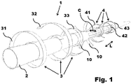
- Figure 1 schematically illustrates pipe 1 during production.
- Figure 2A schematically shows a cross section of part of pipe 1.
- Figure 2B schematically shows the pipe 1 of figure 2A with partly cut away section.
- Pipe 1 is suitable for use in the production of hydrocarbons. All materials used therein need to be able to withstand the high pressure and high temperature that may occur during the production of hydrocarbons. Preferably use is made of thermoplastic materials.
- thermoplastic materials One example of a specifically suitable thermoplastic material is known in the relevant field as (PEEK) polymer, a polyaryletherketone material produced by VICTREX.
- a tubular body 2 is selected for forming an inner conduit of the pipe 1.
- Tube 2 is preferably produced using known extrusion methods.
- the first step optionally further comprises applying an inner cover 3 over the inner conduit 2.
- an inner cover 3 over the inner conduit 2.
- one or more layers 31, 32, 33 are wound around the inner conduit 2 to form the inner cover 3.
- the layers 31-33 may include thermoplastic material, reinforcing material and/or protective material.
- Suitable reinforcing material comprises aramid fibres.
- Suitable protective material provides protection against abrasion.
- a number of spacer elements 10 are attached at a mutual distance to the outer side of the inner conduit 2.
- Each spacer element 10 has a general longitudinal shape.
- the spacer elements 10 can be laid in suitable patterns.
- One preferred pattern involves attaching the spacer elements 10 such that they extend substantially in longitudinal direction over the inner conduit 2. This is shown in figure 1 .
- the longitudinal direction of the pipe 1 is denoted with the arrow and letter L.
- the mutual distance between adjacent spacer elements 10 is denoted with the arrow and letter C.
- the mutual distance C between the spacer elements 10 is a circumferential distance.
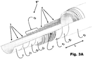
- FIGS 3A and 3B schematically show a pipe 1' with partly cut away section.
- Pipe 1' is an alternative design wherein the spacer elements 10 are attached such that they extend substantially in helical direction around the inner conduit 2.
- the spacer elements are preferably of a non-corrosive metal or a thermoplastic material.
- the spacer elements are preferably arranged substantially equidistant.
- the spacer elements may be cut out of a further tube. Said further tube is selected such that its inner radius substantially corresponds to the outer radius of the tube for forming the inner conduit 2.
- the further tube or the individual spacer elements can also be produced by known methods of extrusion.
- the spacer elements can either be massive or hollow.
- Hollow spacer elements 11 include cavities or channels allowing flow of material through the spacer elements.
- the spacer elements 10 are first placed in the desired pattern and then adhered to the inner conduit 2.
- Suitable adhesive materials may be used.
- the pipe may be heated at least in part up to the softening temperature of the thermoplastic materials during a predetermined time period for adhering the spacer elements 10 to the inner conduit 2.
- Suitable heating means may include a laser to temporary heat the contacting surfaces of the spacer elements 10 with the inner conduit 2.
- an outer cover 4 is applied around the inner conduit 2 and the spacer elements 10.
- cavities or channels 5 are enclosed by the inner conduit 2, the spacer elements 10 and the outer cover 4.
- one or more layers 41, 42, 43 are wound around the inner conduit 2 and the spacer elements 10 to form outer cover 4.
- the layers 41-43 may include thermoplastic material, reinforcing material and/or protective material.
- Suitable reinforcing material comprises aramid fibres.
- Suitable protective material provides protection against abrasion.
- a final step of the method comprises adhering the spacer elements 10 to the outer cover 4 as well as adhering the layers to form the outer cover.
- Suitable adhesive materials may be used.
- adhering may be accomplished by heating the pipe at least in part up to the softening temperature of the thermoplastic materials during a predetermined time period.
- Suitable heating means may include a laser to temporary heat the contacting surfaces of the spacer elements 10 with the outer cover 4 and the layers therein.
- the cavities or channels 5 are fluid tight and suitable for use as fluid passageways in the production of hydrocarbons.
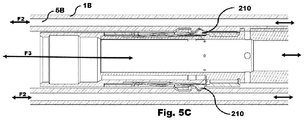
- Inlet/outlet openings can be arranged in the wall of the pipe to allow fluid to flow between the inner conduit 2 and the cavities 5 and/or between the cavities 5 and the surroundings of the pipe 1. This is illustrated in figures 5A , 5B and 5C .
- Figure 4A schematically shows a system of pipes 1 coupled by coupling elements 6 according to the invention.
- the coupling elements 6 are arranged to provide for continuous passageways through the coupled pipes.
- the inner conduits 2 of adjacent pipes form a continuous inner channel.
- the cavities 5 or 15 of adjacent pipes form continuous outer channels.
- a longitudinal housing 100 is coupled at both outer ends to a flexible pipe 1 according to the invention.
- the housing is an example of a tubing arranged to receive plug-in devices of the WROP-system as described in WO2014/011043 .
- FIG 4B schematically shows the system of figure 4A in decoupled state.
- Coupling element 6 is shown in more detail in figure 4C .
- Coupling element 6 comprises a male part 63 and a female part 64 for receiving the male part 63 and a joint element 61 for placement between the flexible pipes 1 or 100.
- the joint element comprises an inner opening 62 and surrounding outer openings 65 and further comprises through holes 66 for longitudinal fasteners 67, such as bolts.
- the joint element 61 is enclosed therein.
- the dimensions of the inner opening 62 of the coupling element 6 correspond to the dimensions of the inner conduit 2 of pipe 1.
- the dimensions of the outer openings 65 of the coupling element 6 correspond to the dimensions of the cavities 5 or 15 of pipe 1.
- the dashed arrows indicate passageways for materials and the dashed lines indicate the through holes for the fasteners.
- the joint element 61 is generally ring shaped.
- the outer openings 65 and the holes 66 are arranged alternately over the joint element 61.
- the holes 66 are recessed with respect to the outer openings 65.
- the shape of the outer openings 65 corresponds to the shape of the cavities 5 of the pipe 1.
- the mating shape of the joint element 61 and the outer ends of the flexible pipes 1 allow for a fluid tight seal.
- slots 69 are arranged for receiving the fasteners 67.
- two pairs of three bolts each face each other.
- the female part 64 has inner thread and the male part 63 has outer thread.
- Coupling element 6 can be coupled and decoupled manually.
- the coupling element according to this disclosure can further be connected to the following non-limited enumeration of examples:
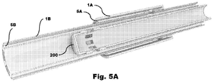
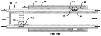
- FIGS 5A through 5C illustrate a pair of pipes 1A, 1B that are coaxially arranged and accommodate equipment 200.
- equipment is a plug-in device of the WROP-system as described in Fluid flow in the cavities 5A of outer pipe 1A is indicated with arrow F1.
- a substantially parallel fluid flow in the cavities 5B of inner pipe 1B is indicated with arrow F2.
- a substantially parallel fluid flow through the equipment 200 is indicated with arrow F3.
- Inlet/outlet openings 51 are arranged in adjacent walls of the pipes 1A, 1B to allow fluid flow R1 between the cavities 5A and 5B.
- Inlet/outlet openings 52 are arranged in the wall of the pipe 1B to allow fluid flow R2 between the cavities 5B and openings in the equipment 200.
- the inlet/outlet openings are sealed, as illustrated by seals 53 adjacent to inlet/outlet openings 51.
- Suitable fixation means 210 are present to fixate the equipment 200 in the pipe 1B.
- the present invention is elucidated by means of preferred embodiments for use in the production of hydrocarbons. Nevertheless it is stretched that the pipe is generally suitable for transporting material flows, including fluid, gases, or particles, and is generally suitable for transporting all types of material flows even in highly demanding circumstances.
Landscapes
- Engineering & Computer Science (AREA)
- General Engineering & Computer Science (AREA)
- Mechanical Engineering (AREA)
- Rigid Pipes And Flexible Pipes (AREA)
Claims (6)
- System umfassend flexible Rohre (1) und Kupplungselemente (6) zum Kuppeln der flexiblen Rohre, wobei die flexiblen Rohre jeweils eine innere Leitung (2) und mehrere Hohlräume (5) aufweisen, die im Wesentlichen parallel über die Außenfläche der inneren Leitung verlaufen, und wobei die Kupplungselemente eine innere Öffnung (62) und mehrere äußere Öffnungen (65) aufweisen, die die innere Öffnung umgeben, derart, dass im gekuppelten Zustand die inneren Leitungen (2) benachbarter flexibler Rohre mittels der inneren Öffnung (62) des dazwischen angeordneten Kupplungselements (6) und die Hohlräume (5) benachbarter flexibler Rohre (1) mittels der äußeren Öffnungen (65) des dazwischen angeordneten Kupplungselements verbunden sind, wobei jedes Kupplungselement (6) einen männlichen Teil (63) und einen weiblichen Teil (64) zur Aufnahme des männlichen Teils und ein Verbindungselement (61) zur Anordnung zwischen zwei flexiblen Rohren umfasst, wobei das Verbindungselement die innere Öffnung (62) und die äußeren Öffnungen (65) umfasst, wobei die Abmessungen der inneren Öffnung (62) den Abmessungen der inneren Leitung (2) und die Abmessungen der äußeren Öffnungen (65) den Abmessungen der Hohlräume (5) entsprechen, um gerade Durchgänge zwischen benachbarten flexiblen Rohren zu bilden, dadurch gekennzeichnet, daß das Verbindungselement (61) ferner Durchgangslöcher (66) für Längsbefestigungselemente (67) aufweist, wobei die flexiblen Rohre an ihren äußeren Enden zur Aufnahme der Längsbefestigungselemente angeordnet sind.
- System nach Anspruch 1, wobei im gekoppelten Zustand des Kupplungselements (6) das Verbindungselement (61) in dem Kupplungselement (6) eingeschlossen ist.
- System nach Anspruch 1 oder 2, wobei der weibliche Teil (64) ein Innengewinde und der männliche Teil (63) ein Außengewinde aufweist.
- System nach Anspruch 1, 2 oder 3, wobei jedes Rohr (1) folgendes umfaßt:a) eine innere Leitung (2);b) eine Anzahl von Abstandselementen (10) mit einer im Allgemeinen länglichen Form, die in einem gegenseitigen Abstand an der Außenseite der inneren Leitung befestigt sind;c) eine äußere Abdeckung (4), die durch eine oder mehrere Schichten (41, 42, 43) aus thermoplastischem Material gebildet ist, die um die innere Leitung (2) und die Abstandselemente (10) herum befestigt sind, dadurch gekennzeichnet, dass zwischen der inneren Leitung (2), den Abstandselementen (10) und der äußeren Abdeckung (4) Längshohlräume (5) gebildet sind, die zur Verwendung als Durchgänge für Gegenstände geeignet sind.
- System nach Anspruch 4, wobei die innere Leitung (2) eine innere Abdeckung (3) umfasst, die aus einer oder mehreren Schichten (31, 32, 33) aus thermoplastischem Material gebildet ist, die um die innere Leitung herum befestigt sind.
- System nach einem oder mehreren der vorstehenden Ansprüche, bei dem Einlaß/Auslaßöffnungen (51, 52) in der Wand des Rohres angeordnet sind, um das Ein/Ausfließen von Material in/aus den Hohlräumen (5) zu ermöglichen.
Applications Claiming Priority (2)
| Application Number | Priority Date | Filing Date | Title |
|---|---|---|---|
| NL2013043A NL2013043B1 (en) | 2014-06-20 | 2014-06-20 | System of flexible pipes and coupling elements and method of producing such a flexible pipe. |
| PCT/NL2015/050448 WO2015194955A1 (en) | 2014-06-20 | 2015-06-19 | System of flexible pipes and coupling elements and method of producing such a flexible pipe |
Publications (2)
| Publication Number | Publication Date |
|---|---|
| EP3158247A1 EP3158247A1 (de) | 2017-04-26 |
| EP3158247B1 true EP3158247B1 (de) | 2020-06-24 |
Family
ID=51398811
Family Applications (1)
| Application Number | Title | Priority Date | Filing Date |
|---|---|---|---|
| EP15745252.5A Not-in-force EP3158247B1 (de) | 2014-06-20 | 2015-06-19 | System aus flexiblen rohren und kopplungselementen und verfahren zur herstellung solch eines flexiblen rohrs |
Country Status (4)
| Country | Link |
|---|---|
| US (1) | US10890287B2 (de) |
| EP (1) | EP3158247B1 (de) |
| NL (1) | NL2013043B1 (de) |
| WO (1) | WO2015194955A1 (de) |
Families Citing this family (2)
| Publication number | Priority date | Publication date | Assignee | Title |
|---|---|---|---|---|
| WO2018233790A1 (en) * | 2017-06-22 | 2018-12-27 | National Oilwell Varco Denmark I/S | A flexible pipe and a method for equalizing pressure in a flexible pipe |
| US11021915B2 (en) * | 2018-10-16 | 2021-06-01 | Saudi Arabian Oil Company | Systems and methods for reducing the effect of borehole tortuosity on the deployment of a completion assembly |
Family Cites Families (11)
| Publication number | Priority date | Publication date | Assignee | Title |
|---|---|---|---|---|
| US1736923A (en) * | 1927-04-30 | 1929-11-26 | Lalonde William James | Hose coupling |
| US2650112A (en) * | 1949-02-02 | 1953-08-25 | Williams Wallace Company | Double walled pipe and coupling therefor |
| US4341392A (en) * | 1975-10-03 | 1982-07-27 | Wavin B.V. | Plastics pipes having walls with lengthwise extending channels |
| US5423353A (en) * | 1993-09-17 | 1995-06-13 | Sorensen; Jeff | Hose |
| US5713607A (en) * | 1994-09-15 | 1998-02-03 | Environ Products, Inc. | Pipe coupling assembly, system and method |
| DE69928076T2 (de) | 1999-03-23 | 2006-07-13 | Gaimont Universal Ltd. B.V.I. | Extrudrierte, mehrfachrohrförmige Vorrichtung |
| EP1731823A1 (de) * | 2005-06-08 | 2006-12-13 | Single Buoy Moorings Inc. | Schlauch zum Befördern von kryogenen Fluiden |
| US8839822B2 (en) * | 2006-03-22 | 2014-09-23 | National Oilwell Varco, L.P. | Dual containment systems, methods and kits |
| DE102008021201A1 (de) * | 2008-04-28 | 2009-11-05 | H. Butting Gmbh & Co. Kg | Förderrohrleitungssystem |
| US9523446B2 (en) | 2011-01-06 | 2016-12-20 | National Oilwell Varco Denmark I/S | Unbonded flexible pipe |
| NL2009165C2 (en) | 2012-07-10 | 2014-01-13 | Steenmaat Beheer B V | System and method for production of a primary fluid, such as oil, from an underground reservoir. |
-
2014
- 2014-06-20 NL NL2013043A patent/NL2013043B1/en not_active IP Right Cessation
-
2015
- 2015-06-19 US US15/320,271 patent/US10890287B2/en not_active Expired - Fee Related
- 2015-06-19 WO PCT/NL2015/050448 patent/WO2015194955A1/en not_active Ceased
- 2015-06-19 EP EP15745252.5A patent/EP3158247B1/de not_active Not-in-force
Non-Patent Citations (1)
| Title |
|---|
| None * |
Also Published As
| Publication number | Publication date |
|---|---|
| WO2015194955A1 (en) | 2015-12-23 |
| EP3158247A1 (de) | 2017-04-26 |
| US20170184243A1 (en) | 2017-06-29 |
| US10890287B2 (en) | 2021-01-12 |
| NL2013043B1 (en) | 2016-07-06 |
Similar Documents
| Publication | Publication Date | Title |
|---|---|---|
| US9765912B2 (en) | Telescoping pipe coupling | |
| EP2472053B1 (de) | Bohrlochvorrichtung und -verfahren | |
| US9303478B2 (en) | Downhole tool and method for passing control line through tool | |
| CN105163878B (zh) | 挠性管和制造挠性管的方法 | |
| CN105378361B (zh) | 软管与间隔部件的连接套接管、相关的软管和方法 | |
| BR112021005747B1 (pt) | Sistema para criação de uma conexão entre um primeiro elemento de estrutura tubular e um segundo elemento de estrutura tubular e conexão para uso no sistema | |
| BR112016025665B1 (pt) | Duto flexível de camadas não aderentes para transportar um material abrasivo, método para fabricar um duto flexível de camadas não aderentes para transportar um material abrasivo e uso de um duto | |
| CN104685280B (zh) | 用于强化复合管的方法 | |
| CN110832242B (zh) | 弯曲限制器 | |
| BR112017023206B1 (pt) | Método de re-terminar uma extremidade de um tubo flexível | |
| CN109416138B (zh) | 气体排放 | |
| US9593793B2 (en) | Chained clamp pipeline repair structure and method of use | |
| CN115315591B (zh) | 楔形突出轮廓配件密封件系统及方法 | |
| BR112018072192B1 (pt) | Método de despressurização para equipamento submarino | |
| US10890287B2 (en) | System of flexible pipes and coupling elements and method of producing such a flexible pipe | |
| US20160076684A1 (en) | Load bearing flexible conduit | |
| CN106662280A (zh) | 模块化管道系统和组件 | |
| US8910979B1 (en) | Pipe repair coupling | |
| WO2021183766A1 (en) | Methods, systems, and apparatus for providing access for telecommunication cables in utility piping | |
| EP3066374B1 (de) | Fluidverbindung | |
| CN113272584B (zh) | 用于捕集来自受损管线的意外加压流体泄露的柔性管道和方法 | |
| RU2407935C1 (ru) | Резиновая манжета | |
| RU2673475C1 (ru) | Элемент длинномерной гибкой колонны (варианты) | |
| CA2824917A1 (en) | System and method for coupling pipes | |
| JP2009014149A (ja) | 補修用管および配管補修方法 |
Legal Events
| Date | Code | Title | Description |
|---|---|---|---|
| STAA | Information on the status of an ep patent application or granted ep patent |
Free format text: STATUS: THE INTERNATIONAL PUBLICATION HAS BEEN MADE |
|
| PUAI | Public reference made under article 153(3) epc to a published international application that has entered the european phase |
Free format text: ORIGINAL CODE: 0009012 |
|
| STAA | Information on the status of an ep patent application or granted ep patent |
Free format text: STATUS: REQUEST FOR EXAMINATION WAS MADE |
|
| 17P | Request for examination filed |
Effective date: 20170120 |
|
| AK | Designated contracting states |
Kind code of ref document: A1 Designated state(s): AL AT BE BG CH CY CZ DE DK EE ES FI FR GB GR HR HU IE IS IT LI LT LU LV MC MK MT NL NO PL PT RO RS SE SI SK SM TR |
|
| AX | Request for extension of the european patent |
Extension state: BA ME |
|
| DAV | Request for validation of the european patent (deleted) | ||
| DAX | Request for extension of the european patent (deleted) | ||
| RAP1 | Party data changed (applicant data changed or rights of an application transferred) |
Owner name: KARIZAN B.V. |
|
| STAA | Information on the status of an ep patent application or granted ep patent |
Free format text: STATUS: EXAMINATION IS IN PROGRESS |
|
| 17Q | First examination report despatched |
Effective date: 20190729 |
|
| GRAP | Despatch of communication of intention to grant a patent |
Free format text: ORIGINAL CODE: EPIDOSNIGR1 |
|
| STAA | Information on the status of an ep patent application or granted ep patent |
Free format text: STATUS: GRANT OF PATENT IS INTENDED |
|
| INTG | Intention to grant announced |
Effective date: 20200123 |
|
| GRAS | Grant fee paid |
Free format text: ORIGINAL CODE: EPIDOSNIGR3 |
|
| GRAA | (expected) grant |
Free format text: ORIGINAL CODE: 0009210 |
|
| STAA | Information on the status of an ep patent application or granted ep patent |
Free format text: STATUS: THE PATENT HAS BEEN GRANTED |
|
| AK | Designated contracting states |
Kind code of ref document: B1 Designated state(s): AL AT BE BG CH CY CZ DE DK EE ES FI FR GB GR HR HU IE IS IT LI LT LU LV MC MK MT NL NO PL PT RO RS SE SI SK SM TR |
|
| REG | Reference to a national code |
Ref country code: GB Ref legal event code: FG4D |
|
| REG | Reference to a national code |
Ref country code: CH Ref legal event code: EP |
|
| REG | Reference to a national code |
Ref country code: DE Ref legal event code: R096 Ref document number: 602015054704 Country of ref document: DE |
|
| REG | Reference to a national code |
Ref country code: AT Ref legal event code: REF Ref document number: 1284230 Country of ref document: AT Kind code of ref document: T Effective date: 20200715 |
|
| REG | Reference to a national code |
Ref country code: IE Ref legal event code: FG4D |
|
| REG | Reference to a national code |
Ref country code: SE Ref legal event code: TRGR |
|
| REG | Reference to a national code |
Ref country code: NL Ref legal event code: FP |
|
| PG25 | Lapsed in a contracting state [announced via postgrant information from national office to epo] |
Ref country code: GR Free format text: LAPSE BECAUSE OF FAILURE TO SUBMIT A TRANSLATION OF THE DESCRIPTION OR TO PAY THE FEE WITHIN THE PRESCRIBED TIME-LIMIT Effective date: 20200925 Ref country code: FI Free format text: LAPSE BECAUSE OF FAILURE TO SUBMIT A TRANSLATION OF THE DESCRIPTION OR TO PAY THE FEE WITHIN THE PRESCRIBED TIME-LIMIT Effective date: 20200624 Ref country code: NO Free format text: LAPSE BECAUSE OF FAILURE TO SUBMIT A TRANSLATION OF THE DESCRIPTION OR TO PAY THE FEE WITHIN THE PRESCRIBED TIME-LIMIT Effective date: 20200924 Ref country code: LT Free format text: LAPSE BECAUSE OF FAILURE TO SUBMIT A TRANSLATION OF THE DESCRIPTION OR TO PAY THE FEE WITHIN THE PRESCRIBED TIME-LIMIT Effective date: 20200624 |
|
| REG | Reference to a national code |
Ref country code: LT Ref legal event code: MG4D |
|
| PG25 | Lapsed in a contracting state [announced via postgrant information from national office to epo] |
Ref country code: HR Free format text: LAPSE BECAUSE OF FAILURE TO SUBMIT A TRANSLATION OF THE DESCRIPTION OR TO PAY THE FEE WITHIN THE PRESCRIBED TIME-LIMIT Effective date: 20200624 Ref country code: LV Free format text: LAPSE BECAUSE OF FAILURE TO SUBMIT A TRANSLATION OF THE DESCRIPTION OR TO PAY THE FEE WITHIN THE PRESCRIBED TIME-LIMIT Effective date: 20200624 Ref country code: RS Free format text: LAPSE BECAUSE OF FAILURE TO SUBMIT A TRANSLATION OF THE DESCRIPTION OR TO PAY THE FEE WITHIN THE PRESCRIBED TIME-LIMIT Effective date: 20200624 Ref country code: BG Free format text: LAPSE BECAUSE OF FAILURE TO SUBMIT A TRANSLATION OF THE DESCRIPTION OR TO PAY THE FEE WITHIN THE PRESCRIBED TIME-LIMIT Effective date: 20200924 |
|
| REG | Reference to a national code |
Ref country code: AT Ref legal event code: MK05 Ref document number: 1284230 Country of ref document: AT Kind code of ref document: T Effective date: 20200624 |
|
| PG25 | Lapsed in a contracting state [announced via postgrant information from national office to epo] |
Ref country code: AL Free format text: LAPSE BECAUSE OF FAILURE TO SUBMIT A TRANSLATION OF THE DESCRIPTION OR TO PAY THE FEE WITHIN THE PRESCRIBED TIME-LIMIT Effective date: 20200624 |
|
| PG25 | Lapsed in a contracting state [announced via postgrant information from national office to epo] |
Ref country code: PT Free format text: LAPSE BECAUSE OF FAILURE TO SUBMIT A TRANSLATION OF THE DESCRIPTION OR TO PAY THE FEE WITHIN THE PRESCRIBED TIME-LIMIT Effective date: 20201026 Ref country code: ES Free format text: LAPSE BECAUSE OF FAILURE TO SUBMIT A TRANSLATION OF THE DESCRIPTION OR TO PAY THE FEE WITHIN THE PRESCRIBED TIME-LIMIT Effective date: 20200624 Ref country code: CZ Free format text: LAPSE BECAUSE OF FAILURE TO SUBMIT A TRANSLATION OF THE DESCRIPTION OR TO PAY THE FEE WITHIN THE PRESCRIBED TIME-LIMIT Effective date: 20200624 Ref country code: AT Free format text: LAPSE BECAUSE OF FAILURE TO SUBMIT A TRANSLATION OF THE DESCRIPTION OR TO PAY THE FEE WITHIN THE PRESCRIBED TIME-LIMIT Effective date: 20200624 Ref country code: EE Free format text: LAPSE BECAUSE OF FAILURE TO SUBMIT A TRANSLATION OF THE DESCRIPTION OR TO PAY THE FEE WITHIN THE PRESCRIBED TIME-LIMIT Effective date: 20200624 Ref country code: SM Free format text: LAPSE BECAUSE OF FAILURE TO SUBMIT A TRANSLATION OF THE DESCRIPTION OR TO PAY THE FEE WITHIN THE PRESCRIBED TIME-LIMIT Effective date: 20200624 Ref country code: RO Free format text: LAPSE BECAUSE OF FAILURE TO SUBMIT A TRANSLATION OF THE DESCRIPTION OR TO PAY THE FEE WITHIN THE PRESCRIBED TIME-LIMIT Effective date: 20200624 |
|
| PG25 | Lapsed in a contracting state [announced via postgrant information from national office to epo] |
Ref country code: SK Free format text: LAPSE BECAUSE OF FAILURE TO SUBMIT A TRANSLATION OF THE DESCRIPTION OR TO PAY THE FEE WITHIN THE PRESCRIBED TIME-LIMIT Effective date: 20200624 Ref country code: PL Free format text: LAPSE BECAUSE OF FAILURE TO SUBMIT A TRANSLATION OF THE DESCRIPTION OR TO PAY THE FEE WITHIN THE PRESCRIBED TIME-LIMIT Effective date: 20200624 Ref country code: IS Free format text: LAPSE BECAUSE OF FAILURE TO SUBMIT A TRANSLATION OF THE DESCRIPTION OR TO PAY THE FEE WITHIN THE PRESCRIBED TIME-LIMIT Effective date: 20201024 |
|
| REG | Reference to a national code |
Ref country code: DE Ref legal event code: R097 Ref document number: 602015054704 Country of ref document: DE |
|
| PG25 | Lapsed in a contracting state [announced via postgrant information from national office to epo] |
Ref country code: DK Free format text: LAPSE BECAUSE OF FAILURE TO SUBMIT A TRANSLATION OF THE DESCRIPTION OR TO PAY THE FEE WITHIN THE PRESCRIBED TIME-LIMIT Effective date: 20200624 |
|
| PLBE | No opposition filed within time limit |
Free format text: ORIGINAL CODE: 0009261 |
|
| STAA | Information on the status of an ep patent application or granted ep patent |
Free format text: STATUS: NO OPPOSITION FILED WITHIN TIME LIMIT |
|
| 26N | No opposition filed |
Effective date: 20210325 |
|
| PGFP | Annual fee paid to national office [announced via postgrant information from national office to epo] |
Ref country code: IT Payment date: 20210625 Year of fee payment: 7 |
|
| PG25 | Lapsed in a contracting state [announced via postgrant information from national office to epo] |
Ref country code: SI Free format text: LAPSE BECAUSE OF FAILURE TO SUBMIT A TRANSLATION OF THE DESCRIPTION OR TO PAY THE FEE WITHIN THE PRESCRIBED TIME-LIMIT Effective date: 20200624 |
|
| PGFP | Annual fee paid to national office [announced via postgrant information from national office to epo] |
Ref country code: SE Payment date: 20210622 Year of fee payment: 7 |
|
| PG25 | Lapsed in a contracting state [announced via postgrant information from national office to epo] |
Ref country code: MC Free format text: LAPSE BECAUSE OF FAILURE TO SUBMIT A TRANSLATION OF THE DESCRIPTION OR TO PAY THE FEE WITHIN THE PRESCRIBED TIME-LIMIT Effective date: 20200624 |
|
| REG | Reference to a national code |
Ref country code: CH Ref legal event code: PL |
|
| REG | Reference to a national code |
Ref country code: BE Ref legal event code: MM Effective date: 20210630 |
|
| PG25 | Lapsed in a contracting state [announced via postgrant information from national office to epo] |
Ref country code: LU Free format text: LAPSE BECAUSE OF NON-PAYMENT OF DUE FEES Effective date: 20210619 |
|
| PG25 | Lapsed in a contracting state [announced via postgrant information from national office to epo] |
Ref country code: LI Free format text: LAPSE BECAUSE OF NON-PAYMENT OF DUE FEES Effective date: 20210630 Ref country code: IE Free format text: LAPSE BECAUSE OF NON-PAYMENT OF DUE FEES Effective date: 20210619 Ref country code: CH Free format text: LAPSE BECAUSE OF NON-PAYMENT OF DUE FEES Effective date: 20210630 |
|
| PG25 | Lapsed in a contracting state [announced via postgrant information from national office to epo] |
Ref country code: BE Free format text: LAPSE BECAUSE OF NON-PAYMENT OF DUE FEES Effective date: 20210630 |
|
| REG | Reference to a national code |
Ref country code: SE Ref legal event code: EUG |
|
| PG25 | Lapsed in a contracting state [announced via postgrant information from national office to epo] |
Ref country code: SE Free format text: LAPSE BECAUSE OF NON-PAYMENT OF DUE FEES Effective date: 20220620 |
|
| PG25 | Lapsed in a contracting state [announced via postgrant information from national office to epo] |
Ref country code: HU Free format text: LAPSE BECAUSE OF FAILURE TO SUBMIT A TRANSLATION OF THE DESCRIPTION OR TO PAY THE FEE WITHIN THE PRESCRIBED TIME-LIMIT; INVALID AB INITIO Effective date: 20150619 |
|
| PG25 | Lapsed in a contracting state [announced via postgrant information from national office to epo] |
Ref country code: CY Free format text: LAPSE BECAUSE OF FAILURE TO SUBMIT A TRANSLATION OF THE DESCRIPTION OR TO PAY THE FEE WITHIN THE PRESCRIBED TIME-LIMIT Effective date: 20200624 |
|
| PG25 | Lapsed in a contracting state [announced via postgrant information from national office to epo] |
Ref country code: IT Free format text: LAPSE BECAUSE OF NON-PAYMENT OF DUE FEES Effective date: 20220619 |
|
| PGFP | Annual fee paid to national office [announced via postgrant information from national office to epo] |
Ref country code: FR Payment date: 20230403 Year of fee payment: 9 Ref country code: DE Payment date: 20230404 Year of fee payment: 9 |
|
| PG25 | Lapsed in a contracting state [announced via postgrant information from national office to epo] |
Ref country code: MK Free format text: LAPSE BECAUSE OF FAILURE TO SUBMIT A TRANSLATION OF THE DESCRIPTION OR TO PAY THE FEE WITHIN THE PRESCRIBED TIME-LIMIT Effective date: 20200624 |
|
| PGFP | Annual fee paid to national office [announced via postgrant information from national office to epo] |
Ref country code: NL Payment date: 20240403 Year of fee payment: 10 |
|
| PG25 | Lapsed in a contracting state [announced via postgrant information from national office to epo] |
Ref country code: TR Free format text: LAPSE BECAUSE OF FAILURE TO SUBMIT A TRANSLATION OF THE DESCRIPTION OR TO PAY THE FEE WITHIN THE PRESCRIBED TIME-LIMIT Effective date: 20200624 |
|
| PGFP | Annual fee paid to national office [announced via postgrant information from national office to epo] |
Ref country code: GB Payment date: 20240403 Year of fee payment: 10 |
|
| PG25 | Lapsed in a contracting state [announced via postgrant information from national office to epo] |
Ref country code: MT Free format text: LAPSE BECAUSE OF FAILURE TO SUBMIT A TRANSLATION OF THE DESCRIPTION OR TO PAY THE FEE WITHIN THE PRESCRIBED TIME-LIMIT Effective date: 20200624 |
|
| PG25 | Lapsed in a contracting state [announced via postgrant information from national office to epo] |
Ref country code: FR Free format text: LAPSE BECAUSE OF NON-PAYMENT OF DUE FEES Effective date: 20240630 |
|
| REG | Reference to a national code |
Ref country code: DE Ref legal event code: R119 Ref document number: 602015054704 Country of ref document: DE |
|
| REG | Reference to a national code |
Ref country code: NL Ref legal event code: MM Effective date: 20250701 |
|
| GBPC | Gb: european patent ceased through non-payment of renewal fee |
Effective date: 20250619 |
|
| PG25 | Lapsed in a contracting state [announced via postgrant information from national office to epo] |
Ref country code: NL Free format text: LAPSE BECAUSE OF NON-PAYMENT OF DUE FEES Effective date: 20250701 |
|
| PG25 | Lapsed in a contracting state [announced via postgrant information from national office to epo] |
Ref country code: GB Free format text: LAPSE BECAUSE OF NON-PAYMENT OF DUE FEES Effective date: 20250619 |
|
| PG25 | Lapsed in a contracting state [announced via postgrant information from national office to epo] |
Ref country code: DE Free format text: LAPSE BECAUSE OF NON-PAYMENT OF DUE FEES Effective date: 20260101 |