EP3158191B1 - Control of wind turbines in response to wind shear - Google Patents
Control of wind turbines in response to wind shear Download PDFInfo
- Publication number
- EP3158191B1 EP3158191B1 EP15730051.8A EP15730051A EP3158191B1 EP 3158191 B1 EP3158191 B1 EP 3158191B1 EP 15730051 A EP15730051 A EP 15730051A EP 3158191 B1 EP3158191 B1 EP 3158191B1
- Authority
- EP
- European Patent Office
- Prior art keywords
- wind
- blade
- pitch angle
- rotor
- blade pitch
- Prior art date
- Legal status (The legal status is an assumption and is not a legal conclusion. Google has not performed a legal analysis and makes no representation as to the accuracy of the status listed.)
- Active
Links
- 230000004044 response Effects 0.000 title description 2
- 238000005452 bending Methods 0.000 claims description 25
- 238000000034 method Methods 0.000 claims description 13
- 230000001419 dependent effect Effects 0.000 description 8
- 230000006870 function Effects 0.000 description 7
- 125000004122 cyclic group Chemical group 0.000 description 5
- 238000005259 measurement Methods 0.000 description 5
- 230000007423 decrease Effects 0.000 description 3
- 238000012546 transfer Methods 0.000 description 3
- 230000008901 benefit Effects 0.000 description 2
- 230000000694 effects Effects 0.000 description 2
- 239000013598 vector Substances 0.000 description 2
- 230000002411 adverse Effects 0.000 description 1
- 238000013459 approach Methods 0.000 description 1
- 238000012937 correction Methods 0.000 description 1
- 239000000835 fiber Substances 0.000 description 1
- 230000006698 induction Effects 0.000 description 1
- 230000003287 optical effect Effects 0.000 description 1
- 230000009466 transformation Effects 0.000 description 1
- 230000007704 transition Effects 0.000 description 1
Images


Classifications
-
- F—MECHANICAL ENGINEERING; LIGHTING; HEATING; WEAPONS; BLASTING
- F03—MACHINES OR ENGINES FOR LIQUIDS; WIND, SPRING, OR WEIGHT MOTORS; PRODUCING MECHANICAL POWER OR A REACTIVE PROPULSIVE THRUST, NOT OTHERWISE PROVIDED FOR
- F03D—WIND MOTORS
- F03D7/00—Controlling wind motors
- F03D7/02—Controlling wind motors the wind motors having rotation axis substantially parallel to the air flow entering the rotor
- F03D7/022—Adjusting aerodynamic properties of the blades
- F03D7/0224—Adjusting blade pitch
-
- F—MECHANICAL ENGINEERING; LIGHTING; HEATING; WEAPONS; BLASTING
- F03—MACHINES OR ENGINES FOR LIQUIDS; WIND, SPRING, OR WEIGHT MOTORS; PRODUCING MECHANICAL POWER OR A REACTIVE PROPULSIVE THRUST, NOT OTHERWISE PROVIDED FOR
- F03D—WIND MOTORS
- F03D1/00—Wind motors with rotation axis substantially parallel to the air flow entering the rotor
- F03D1/06—Rotors
- F03D1/065—Rotors characterised by their construction elements
- F03D1/0675—Rotors characterised by their construction elements of the blades
-
- F—MECHANICAL ENGINEERING; LIGHTING; HEATING; WEAPONS; BLASTING
- F03—MACHINES OR ENGINES FOR LIQUIDS; WIND, SPRING, OR WEIGHT MOTORS; PRODUCING MECHANICAL POWER OR A REACTIVE PROPULSIVE THRUST, NOT OTHERWISE PROVIDED FOR
- F03D—WIND MOTORS
- F03D7/00—Controlling wind motors
- F03D7/02—Controlling wind motors the wind motors having rotation axis substantially parallel to the air flow entering the rotor
- F03D7/022—Adjusting aerodynamic properties of the blades
- F03D7/024—Adjusting aerodynamic properties of the blades of individual blades
-
- F—MECHANICAL ENGINEERING; LIGHTING; HEATING; WEAPONS; BLASTING
- F03—MACHINES OR ENGINES FOR LIQUIDS; WIND, SPRING, OR WEIGHT MOTORS; PRODUCING MECHANICAL POWER OR A REACTIVE PROPULSIVE THRUST, NOT OTHERWISE PROVIDED FOR
- F03D—WIND MOTORS
- F03D7/00—Controlling wind motors
- F03D7/02—Controlling wind motors the wind motors having rotation axis substantially parallel to the air flow entering the rotor
- F03D7/04—Automatic control; Regulation
- F03D7/042—Automatic control; Regulation by means of an electrical or electronic controller
- F03D7/047—Automatic control; Regulation by means of an electrical or electronic controller characterised by the controller architecture, e.g. multiple processors or data communications
-
- F—MECHANICAL ENGINEERING; LIGHTING; HEATING; WEAPONS; BLASTING
- F05—INDEXING SCHEMES RELATING TO ENGINES OR PUMPS IN VARIOUS SUBCLASSES OF CLASSES F01-F04
- F05B—INDEXING SCHEME RELATING TO WIND, SPRING, WEIGHT, INERTIA OR LIKE MOTORS, TO MACHINES OR ENGINES FOR LIQUIDS COVERED BY SUBCLASSES F03B, F03D AND F03G
- F05B2270/00—Control
- F05B2270/10—Purpose of the control system
- F05B2270/20—Purpose of the control system to optimise the performance of a machine
-
- F—MECHANICAL ENGINEERING; LIGHTING; HEATING; WEAPONS; BLASTING
- F05—INDEXING SCHEMES RELATING TO ENGINES OR PUMPS IN VARIOUS SUBCLASSES OF CLASSES F01-F04
- F05B—INDEXING SCHEME RELATING TO WIND, SPRING, WEIGHT, INERTIA OR LIKE MOTORS, TO MACHINES OR ENGINES FOR LIQUIDS COVERED BY SUBCLASSES F03B, F03D AND F03G
- F05B2270/00—Control
- F05B2270/30—Control parameters, e.g. input parameters
- F05B2270/304—Spool rotational speed
-
- F—MECHANICAL ENGINEERING; LIGHTING; HEATING; WEAPONS; BLASTING
- F05—INDEXING SCHEMES RELATING TO ENGINES OR PUMPS IN VARIOUS SUBCLASSES OF CLASSES F01-F04
- F05B—INDEXING SCHEME RELATING TO WIND, SPRING, WEIGHT, INERTIA OR LIKE MOTORS, TO MACHINES OR ENGINES FOR LIQUIDS COVERED BY SUBCLASSES F03B, F03D AND F03G
- F05B2270/00—Control
- F05B2270/30—Control parameters, e.g. input parameters
- F05B2270/32—Wind speeds
-
- F—MECHANICAL ENGINEERING; LIGHTING; HEATING; WEAPONS; BLASTING
- F05—INDEXING SCHEMES RELATING TO ENGINES OR PUMPS IN VARIOUS SUBCLASSES OF CLASSES F01-F04
- F05B—INDEXING SCHEME RELATING TO WIND, SPRING, WEIGHT, INERTIA OR LIKE MOTORS, TO MACHINES OR ENGINES FOR LIQUIDS COVERED BY SUBCLASSES F03B, F03D AND F03G
- F05B2270/00—Control
- F05B2270/30—Control parameters, e.g. input parameters
- F05B2270/327—Rotor or generator speeds
-
- F—MECHANICAL ENGINEERING; LIGHTING; HEATING; WEAPONS; BLASTING
- F05—INDEXING SCHEMES RELATING TO ENGINES OR PUMPS IN VARIOUS SUBCLASSES OF CLASSES F01-F04
- F05B—INDEXING SCHEME RELATING TO WIND, SPRING, WEIGHT, INERTIA OR LIKE MOTORS, TO MACHINES OR ENGINES FOR LIQUIDS COVERED BY SUBCLASSES F03B, F03D AND F03G
- F05B2270/00—Control
- F05B2270/30—Control parameters, e.g. input parameters
- F05B2270/328—Blade pitch angle
-
- F—MECHANICAL ENGINEERING; LIGHTING; HEATING; WEAPONS; BLASTING
- F05—INDEXING SCHEMES RELATING TO ENGINES OR PUMPS IN VARIOUS SUBCLASSES OF CLASSES F01-F04
- F05B—INDEXING SCHEME RELATING TO WIND, SPRING, WEIGHT, INERTIA OR LIKE MOTORS, TO MACHINES OR ENGINES FOR LIQUIDS COVERED BY SUBCLASSES F03B, F03D AND F03G
- F05B2270/00—Control
- F05B2270/30—Control parameters, e.g. input parameters
- F05B2270/329—Azimuth or yaw angle
-
- F—MECHANICAL ENGINEERING; LIGHTING; HEATING; WEAPONS; BLASTING
- F05—INDEXING SCHEMES RELATING TO ENGINES OR PUMPS IN VARIOUS SUBCLASSES OF CLASSES F01-F04
- F05B—INDEXING SCHEME RELATING TO WIND, SPRING, WEIGHT, INERTIA OR LIKE MOTORS, TO MACHINES OR ENGINES FOR LIQUIDS COVERED BY SUBCLASSES F03B, F03D AND F03G
- F05B2270/00—Control
- F05B2270/30—Control parameters, e.g. input parameters
- F05B2270/331—Mechanical loads
-
- Y—GENERAL TAGGING OF NEW TECHNOLOGICAL DEVELOPMENTS; GENERAL TAGGING OF CROSS-SECTIONAL TECHNOLOGIES SPANNING OVER SEVERAL SECTIONS OF THE IPC; TECHNICAL SUBJECTS COVERED BY FORMER USPC CROSS-REFERENCE ART COLLECTIONS [XRACs] AND DIGESTS
- Y02—TECHNOLOGIES OR APPLICATIONS FOR MITIGATION OR ADAPTATION AGAINST CLIMATE CHANGE
- Y02E—REDUCTION OF GREENHOUSE GAS [GHG] EMISSIONS, RELATED TO ENERGY GENERATION, TRANSMISSION OR DISTRIBUTION
- Y02E10/00—Energy generation through renewable energy sources
- Y02E10/70—Wind energy
- Y02E10/72—Wind turbines with rotation axis in wind direction
Definitions
- This invention relates to wind turbines and to methods of controlling wind turbines. It is particularly concerned with the control of wind turbines in response to wind shear.
- Blade pitch control is well known in the wind turbine field. Most commercial wind turbines use collective pitch control in which the pitch of all blades is controlled by changing a common pitch reference. However, it is also known to use a cyclic individual pitch control according to which the pitch of each blade is controlled cyclically as it rotates. The three turbine blades may have a common control which applies a cyclic control to each blade offset by 120°.
- the wind speed on which the correction is based is the wind speed as measured at the nacelle.
- the wind speed across the length of the blade and around the plane of rotation can vary enormously.
- the wind speed at the top and the bottom of the rotor plane, that is furthest from and nearest to the ground can vary by +10% to -15% respectively compared to the wind speed as measured at the nacelle. In cases of higher shears, these deviations may be from +30% at the top and - 40% at the bottom.
- WO 2011/150931 A2 discloses a method for operating a wind turbine comprising the steps of providing a curve defining optimal pitch angle as a function of tip speed ratio for the wind turbine blades or as a function of wind speed and modifying at least a part of the optimal pitch angle curve by applying a safety buffer.
- EP 2 175 131 A2 discloses a wind turbine capable of adjusting a first pitch angle and at least one second pitch angle of at least one rotor blade as a function of the rotational position of the rotor while the rotor of the wind turbine is rotating.
- a method of controlling a wind turbine having a rotor and a plurality of rotor blades comprising obtaining a wind speed value, determining blade loading comprising determining blade bending moments, estimating a component of vertical wind shear across the rotor plane from the wind speed value and an estimate of main bearing tilt moment derived from the blade bending moments, a measure of blade pitch and azimuth angle, determining the tip speed ratio from the wind speed value and the wind velocity over the rotor plane, selecting a curve of tip speed ratio against blade pitch angle based on the estimated vertical wind shear component, selecting a blade pitch angle based on the selected curve and the tip speed ratio, and adjusting the blade pitch in accordance with the selected blade pitch angle.
- the invention also provides a control system for a wind turbine having a rotor and a plurality of rotor blades, the control system comprising a blade load sensor, an azimuth position sensor, a blade pitch position sensor, and a processor for estimating a component of vertical wind shear across the rotor plane, the processor determining flapwise blade bending moments from signals from the blade load sensors, determining an estimate of main bearing tilt moment from the flapwise blade bending moments and the blade pitch position and azimuth position, and estimating the vertical wind shear from the main bearing tilt moment and the wind speed, the processor determining a tip speed ratio from a measure of wind velocity over the rotor plane, and a store of curves of tip speed ratio and blade pitch reference for a given vertical wind shear, the processor determining a blade pitch angle from one of the set of curves based on the estimated vertical wind shear and the tip speed ratio, and a controller for adjusting the pitch angle of at least one of the rotor blades in accordance with the determined blade pitch angle.
- Blade loading may be readily available to a wind turbine controller. Blade loading is measured for many other control purposes. For example, using strain gauges or fibre optical sensors located on the rotor blades.
- the measure of wind shear may be used to estimate the wind velocity over the rotor plane which is used in calculation of the tip speed ratio.
- Tip speed ratio ( ⁇ ) is a well known ratio of the speed of rotation of the tip of the rotor blades to the wind velocity.
- the estimated vertical wind shear may advantageously take into account yaw error to improve the estimate further.
- the wind speed is advantageously determined at the wind turbine nacelle although a wind speed measurement derived or sensed elsewhere may be used.
- the blade pitch angle may be a collective blade pitch angle applied to adjust all of the plurality of rotor blades.
- the blade pitch angle may be an individual blade pitch angle and the selection of the blade pitch angle is performed for each of the plurality of rotor blades.
- the tip speed ratio may be determined at a plurality of positions on the rotor plane and the blade pitch angle selected for each of the plurality of positions. This enables the pitch angle to follow a curve of optimal power coefficient factor Cp at a given tip speed ratio.
- the invention also provides a method of controlling a wind turbine having a rotor and a plurality of rotor blades, comprising obtaining a wind speed value, determining blade loading comprising determining blade bending moments, estimating a component of horizontal wind shear across the rotor plane from an estimate of main bearing yaw moment derived from the blade bending moments, azimuth angle and blade pitch position, determining the tip speed ratio from the wind speed and the wind velocity over the rotor plane, selecting a curve of tip speed ratio against blade pitch angle based on the estimated horizontal wind shear component, selecting a blade pitch angle based on the selected curve and the tip speed ratio, and adjusting the blade pitch in accordance with the selected blade pitch angle.
- the invention further provides a control system, wherein the processor determines the tip speed ratio of a plurality of positions on the rotor plane and determines a pitch angle for each of the plurality of positions.
- Embodiments of the invention have the advantage that a measure of wind shear may easily be estimated using sensors and parameters that are readily available on a wind turbine. The estimated wind shear can then be used, in conjunction with a collective or individual blade pitch strategy to control the turbine blades such that power output can be increased when shear conditions are present across the rotor blade either in the horizontal or vertical directions or both.
- the following description approaches the optimisation of power output under shear conditions from three aspects: the estimation of shear; a collective pitch controller operation on estimated shear; and, alternatively, an individual pitch controller based on shear.
- the embodiments described are suitable for use in high wind shear conditions, the invention is not limited to high shear conditions. However, it will be appreciated that the contribution to power optimisation made by embodiments of the invention will decrease as shear decreases. For the avoidance of doubt, the invention is not limited to any particular type of shear and includes, but is not limited to, vertical and horizontal wind shear.
- Figure 1 shows a schematic of a vertical wind shear estimator. As with all embodiments of the invention described herein, this may be embodied in an on-board wind turbine controller either separately or in addition to existing control functions. Alternatively, it could form part of a power plant controller and be located remote from the turbine.
- the controller comprises a processor and related hardware components including memory and receives inputs from a plurality of sensors which sense parameters that affect operation of the wind turbine.
- Figure 1 shows a main bearing tilt moment estimator 10 which receives as its inputs the azimuth position, the pitch position and a blade edgewise and flapwise bending moment from each blade.
- the flapwise bending moment is the out-of-plane of rotation bending moment and thus very sensitive to blade pitching.
- the calculation of blade flapwise bending moments is well known in the art and may be calculated using strain sensors, for example.
- the blade edgewise bending moments may be calculated, also using strain sensors for example, or estimated.
- the tilt moment is defined as the tilt moment of the main bearing around the x axis.
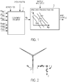
- figure 2 illustrates a wind turbine rotor showing the three blades as blade 1, blade 2 and blade 3 together with x and z axes.
- the azimuth position is a measure of the position of the blades at any given time as they rotate.
- the azimuth position in the rotor plane is defined as the angle between a first blade and the z axis. Separate azimuth positions may be calculated for each blade although all positions may be calculated from a single measurement.
- the tilt moment estimator estimates tilt moments from the flapwise bending moments, an estimate or measure of edgewise bending moments, pitch position and azimuth positions and outputs a tilt moment signal M tilt .
- the tilt moments may be estimated using the well known Coleman coordinate transformation.
- the estimated tilt moments form an input to a wind shear transfer function 12 which also receives a measure of nacelle wind speed.
- the pitch position may be individual or collective.
- the nacelle wind speed may be measured by a variety of means such as a nacelle mounted anemometer. The wind speed need not be measured at the nacelle, but may be measured, for example, at some other point on the wind turbine, or even in advance using a Lidar or other remote sensing device. Alternatively the wind speed may be estimated.
- the wind shear transfer function estimates the vertical wind shear ⁇ for a given input wind speed. This may comprise a store or memory storing curves of wind shear against tilt moment for a plurality of wind speeds.
- FIG. 3 there is shown a generic embodiment which may be used to estimate either vertical or horizontal wind shear.
- the vertical shear is estimated from an estimate of tilt moments based on flapwise and edgewise blade bending moments, pitch position and azimuth position.
- horizontal shear may also be estimated by using the blade flapwise and edgewise bending moments, the blade pitch positions and the azimuth positions to estimate yaw moments.
- the yaw moment is defined as the main bearing moment around the z axis.
- this is represented by tilt and yaw moment estimator 11 which has as its inputs the blade flap and edge moments M flap 1, 2 and 3, and M edge 1, 2 and 3 together with Azimuth and Pitch position as in Figure 1 .
- the vertical wind shear estimation is made as in Figure 1 , except that the estimate may be improved by taking into account a yaw error, being a measure of the misalignment of the rotor with the direction of the wind.
- a yaw error being a measure of the misalignment of the rotor with the direction of the wind.
- the vertical wind shear estimation 12 is shown as having nacelle wind speed, yaw error and tilt moment inputs, and a vertical wind shear output ⁇ v .
- the wind speed may be calculated by a variety of techniques as mentioned above and may be measured at a location other than the nacelle.
- the horizontal wind shear estimator 14 takes as its input, the yaw moment, M yaw provided by the yaw moment estimator. This moment is used, with the nacelle wind speed measurement, or other wind speed measurement as described, to estimate horizontal wind shear. Although not essential, the estimation may be improved by taking into account the inflow angle which is shown as a third input into the estimator. The inflow angle is the angle at which the mean air flow comes into the rotor. As with the vertical shear estimator, the horizontal wind shear estimator may comprise a store of curves of the yaw moment against horizontal wind shear at various wind speeds.
- the tilt and/or yaw moments could be measured directly, for example using strain gauges.
- the yaw error and the inflow angle induce an additional tilt and yaw moment which is taken into account in the respective transfer function, but may be omitted.
- the wind shear is estimated based on a determination of blade loading.
- This loading may be the blade flap load and the blade edge load.
- the edge load may be estimated rather than measured.
- the flap load may also be estimated but modern wind turbines generally have sensors available to measure the load.
- the horizontal wind shear signal ⁇ h and the vertical wind shear signal ⁇ v may be used to estimate the wind velocity vector at any position on the rotor plane.
- a wind velocity estimator 16 which determines wind velocity over the rotor plane and which has inputs of azimuth position, wind speed, yaw error and inflow angle and output a wind velocity.
- the inflow angle may be measured or determined from the terrain on which the wind turbine is mounted.
- the yaw error may be measured from a wind direction sensor.
- the rotor velocity estimator requires a wind shear profile model.
- Various models may be used. For calculation of horizontal wind shear a linear profile may be used; for calculation of vertical wind shear a logarithmic wind profile or power law profile may be used as specified in IEC61400-1-ed3, Section 3.62. Other profiles are possible. An example is shown in Figure 7 described below.
- the estimated wind velocity is used to calculate the optimal tip speed ratio ⁇ and pitch angle ⁇ . This optimum may be found for a collective pitch angle or individual blade pitch angles.
- An example of a collective pitch controller is Figure 4 .
- the input to pitch calculator 18 is the estimated wind shear value ⁇ . This may be the vertical wind shear ⁇ v , the horizontal wind shear ⁇ h or both.
- the estimate of wind velocity as described above is used, together with the measured wind speed to determine the tip-speed ratio ⁇ at unit 20 and the collective pitch reference is generated from a set of optimised curves of tip speed ratio to pitch angle ( ⁇ : ⁇ ) for a given value of wind shear. These optimised curves are predetermined curves which are pre-stored in a memory of the control system.
- Figure 5 shows an example of an individual blade pitch controller based on a wind shear input.
- the optimal individual pitch angle is determined for a specific blade position in the rotor plane.
- the tip speed ratio calculator 22 has inputs of estimated wind shear (either vertical and/or horizontal), estimated wind velocity as described above, and measured wind speed. It then calculates the tip speed ratios at the top and bottom of the rotor plane ( ⁇ top and ⁇ bottom ) and at the hub ( ⁇ hub ).
- a pitch angle calculator 24 which calculates the optimum pitch angles at the top, bottom and hub positions based on the tip speed ratio inputs and a predetermined optimum curve of tip speed ratio to pitch angle ( ⁇ : ⁇ ). This optimum curve is also pre-stored in a memory of the controller.
- the pitch angle calculator 24 outputs pitch angles for the three positions, ⁇ top , ⁇ hub , ⁇ bottom which are provided to an interpolation unit which calculates actual pitch angles ⁇ 1 , ⁇ 2 , ⁇ 3 based on the calculated values and an azimuth position input.
- the estimation of vertical wind shear is based on an estimation of tilt moments.
- the tilt moment is calculated from the flapwise and edgewise blade moments, for example the flapwise/edgewise blade root moments. These moments may be measured using blade load sensors which are well known in the art.
- a strain gauge is one example of many suitable sensors and are usually located at the blade root although other locations are possible
- the main bearing is the bearing connecting the rotor to the main shaft.
- the yaw moment is used similarly to calculate the horizontal wind shear and there is a similar correlation between the horizontal wind shear exponent and the yaw moment.
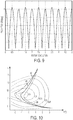
- Figure 7 shows a curve of wind speed and tip speed ratio at different heights along the wind turbine rotor plane in conditions of high positive wind shear.
- the wind speed at the bottom of the rotor plane is lowest due to ground effects and increases towards the top.
- the tip speed ratio is proportional to the inverse of the wind speed.
- V bottom ⁇ 1/ ⁇ bottom ; V H ⁇ 1/ ⁇ H ; and V top ⁇ 1/ ⁇ top varies across the plane of the rotor. This follows as the tip speed is the same for all positions in the rotor plane and so the tip speed ratio decreases at the top of the rotor plane compared to the hub and increases at the bottom of the rotor plane.
- Figure 8 illustrates the advantages of wind shear dependent individual blade pitching.
- Figure 8 shows the power coefficient surface Cp ( ⁇ , ⁇ ).
- References 40, 42, 44 indicate set points at the bottom, hub and top rotor plane positions respectively using a collective pitch angle control.
- Set point 42 is the hub set point which is used in known systems to determine a collective pitch angle based on hub wind speed to optimise the power coefficient.
- Set points 46, 42, 48 are the operating points for individual pitch control.
- Set point 42 is the hub set point and is the same value as the collective example and the prior art example that only uses hub speed.
- the top and bottom operating points 46, 48 are at markedly different pitch angles.
- the three operating points 46, 42, 48 lie on a curve 50 of optimal pitch angle to tip speed ratio.
- the turbine can operate along the optimal pitch angle : tip speed ratio ( ⁇ : A) curve and therefore increase the overall Cp value.
- Figure 9 shows how the individual pitch reference is cyclic. As an example, for a shear coefficient of 0.6, a 2P pitch reference is presently considered optimal as illustrated in Figure 9 where P is the fundamental rotor frequency. This figure shows a pitch curve that is optimised for maximum Cp. In practice it may be necessary to smooth the transitions between the upper and lower parts of the rotor plane.
- results relate to vertical wind shear, but apply also to horizontal wind shear dependent pitch control or horizontal and vertical wind shear dependent pitch control.
Description
- This invention relates to wind turbines and to methods of controlling wind turbines. It is particularly concerned with the control of wind turbines in response to wind shear.
- It is generally desirable to optimise the power output by a wind turbine. During periods of high wind shear the power output may be optimised by changing the pitch angle of the blades. Blade pitch control is well known in the wind turbine field. Most commercial wind turbines use collective pitch control in which the pitch of all blades is controlled by changing a common pitch reference. However, it is also known to use a cyclic individual pitch control according to which the pitch of each blade is controlled cyclically as it rotates. The three turbine blades may have a common control which applies a cyclic control to each blade offset by 120°.
- It is presently known to optimise power output based on an optimal collective pitch angle which is determined from nacelle wind speed and rotor speed. Thus, the wind speed on which the correction is based is the wind speed as measured at the nacelle. However, the wind speed across the length of the blade and around the plane of rotation can vary enormously. With a standard roughness induced wind shear profile, the wind speed at the top and the bottom of the rotor plane, that is furthest from and nearest to the ground, can vary by +10% to -15% respectively compared to the wind speed as measured at the nacelle. In cases of higher shears, these deviations may be from +30% at the top and - 40% at the bottom. In consequence, as the operating pitch set points are determined by nacelle wind speed, the turbine is not operated at optimum set points over the entire sweep of the rotor plane.
WO 2011/150931 A2 discloses a method for operating a wind turbine comprising the steps of providing a curve defining optimal pitch angle as a function of tip speed ratio for the wind turbine blades or as a function of wind speed and modifying at least a part of the optimal pitch angle curve by applying a safety buffer. -
EP 2 175 131 A2 - According to the invention there is provided a method of controlling a wind turbine having a rotor and a plurality of rotor blades, comprising obtaining a wind speed value, determining blade loading comprising determining blade bending moments, estimating a component of vertical wind shear across the rotor plane from the wind speed value and an estimate of main bearing tilt moment derived from the blade bending moments, a measure of blade pitch and azimuth angle, determining the tip speed ratio from the wind speed value and the wind velocity over the rotor plane, selecting a curve of tip speed ratio against blade pitch angle based on the estimated vertical wind shear component, selecting a blade pitch angle based on the selected curve and the tip speed ratio, and adjusting the blade pitch in accordance with the selected blade pitch angle.
- The invention also provides a control system for a wind turbine having a rotor and a plurality of rotor blades, the control system comprising a blade load sensor, an azimuth position sensor, a blade pitch position sensor, and a processor for estimating a component of vertical wind shear across the rotor plane, the processor determining flapwise blade bending moments from signals from the blade load sensors, determining an estimate of main bearing tilt moment from the flapwise blade bending moments and the blade pitch position and azimuth position, and estimating the vertical wind shear from the main bearing tilt moment and the wind speed, the processor determining a tip speed ratio from a measure of wind velocity over the rotor plane, and a store of curves of tip speed ratio and blade pitch reference for a given vertical wind shear, the processor determining a blade pitch angle from one of the set of curves based on the estimated vertical wind shear and the tip speed ratio, and a controller for adjusting the pitch angle of at least one of the rotor blades in accordance with the determined blade pitch angle.
- Measurements of blade loading may be readily available to a wind turbine controller. Blade loading is measured for many other control purposes. For example, using strain gauges or fibre optical sensors located on the rotor blades.
- The measure of wind shear may be used to estimate the wind velocity over the rotor plane which is used in calculation of the tip speed ratio. Tip speed ratio (λ) is a well known ratio of the speed of rotation of the tip of the rotor blades to the wind velocity.
- The estimated vertical wind shear may advantageously take into account yaw error to improve the estimate further.
- The wind speed is advantageously determined at the wind turbine nacelle although a wind speed measurement derived or sensed elsewhere may be used.
- The blade pitch angle may be a collective blade pitch angle applied to adjust all of the plurality of rotor blades. Alternatively, the blade pitch angle may be an individual blade pitch angle and the selection of the blade pitch angle is performed for each of the plurality of rotor blades.
- In the individual blade pitch angle embodiment the tip speed ratio may be determined at a plurality of positions on the rotor plane and the blade pitch angle selected for each of the plurality of positions. This enables the pitch angle to follow a curve of optimal power coefficient factor Cp at a given tip speed ratio.
- The invention also provides a method of controlling a wind turbine having a rotor and a plurality of rotor blades, comprising obtaining a wind speed value, determining blade loading comprising determining blade bending moments, estimating a component of horizontal wind shear across the rotor plane from an estimate of main bearing yaw moment derived from the blade bending moments, azimuth angle and blade pitch position, determining the tip speed ratio from the wind speed and the wind velocity over the rotor plane, selecting a curve of tip speed ratio against blade pitch angle based on the estimated horizontal wind shear component, selecting a blade pitch angle based on the selected curve and the tip speed ratio, and adjusting the blade pitch in accordance with the selected blade pitch angle.
- The invention further provides a control system, wherein the processor determines the tip speed ratio of a plurality of positions on the rotor plane and determines a pitch angle for each of the plurality of positions.
- Embodiments of the invention have the advantage that a measure of wind shear may easily be estimated using sensors and parameters that are readily available on a wind turbine. The estimated wind shear can then be used, in conjunction with a collective or individual blade pitch strategy to control the turbine blades such that power output can be increased when shear conditions are present across the rotor blade either in the horizontal or vertical directions or both.
- Embodiments of the invention will now be described, by way of example only, and with reference to the accompanying drawings, in which:
-
Figure 1 is a schematic view of a vertical wind shear estimator embodying the invention; -
Figure 2 is an exemplary drawing illustrating the x and z axes of a wind turbine rotor; -
Figure 3 is a schematic view of a generalised case of the estimator ofFigure 1 which can estimate horizontal and vertical shear; -
Figure 4 is a schematic view of a shear dependent collective pitch controller embodying the invention; -
Figure 5 is a schematic view of a shear dependent individual blade pitch controller embodying the invention; -
Figure 6 is a graph showing the correlation between tilt moment and wind shear; -
Figure 7 is a schematic view illustrating how vertical wind shear affects tip speed ratio; -
Figure 8 shows a power coefficient surface for collective and individual pitch controllers; -
Figure 9 is a graph of rotor revolution and pitch position illustrating cyclic pitch control; and -
Figure 10 shows a shear dependent opti-θ-λ curve; - The following description approaches the optimisation of power output under shear conditions from three aspects: the estimation of shear; a collective pitch controller operation on estimated shear; and, alternatively, an individual pitch controller based on shear. Although the embodiments described are suitable for use in high wind shear conditions, the invention is not limited to high shear conditions. However, it will be appreciated that the contribution to power optimisation made by embodiments of the invention will decrease as shear decreases. For the avoidance of doubt, the invention is not limited to any particular type of shear and includes, but is not limited to, vertical and horizontal wind shear.
-
Figure 1 shows a schematic of a vertical wind shear estimator. As with all embodiments of the invention described herein, this may be embodied in an on-board wind turbine controller either separately or in addition to existing control functions. Alternatively, it could form part of a power plant controller and be located remote from the turbine. The controller comprises a processor and related hardware components including memory and receives inputs from a plurality of sensors which sense parameters that affect operation of the wind turbine. -
Figure 1 shows a main bearingtilt moment estimator 10 which receives as its inputs the azimuth position, the pitch position and a blade edgewise and flapwise bending moment from each blade. In this example, there are three blades providing three flapwise bending moments,M flap1,M flap2 andM flap3 and three edgewise bending moments, Medge1,M edge2 andM edge3. The flapwise bending moment is the out-of-plane of rotation bending moment and thus very sensitive to blade pitching. The calculation of blade flapwise bending moments is well known in the art and may be calculated using strain sensors, for example. The blade edgewise bending moments may be calculated, also using strain sensors for example, or estimated. The tilt moment is defined as the tilt moment of the main bearing around the x axis. For ease of understanding,figure 2 illustrates a wind turbine rotor showing the three blades asblade 1,blade 2 andblade 3 together with x and z axes. - The azimuth position is a measure of the position of the blades at any given time as they rotate. The azimuth position in the rotor plane is defined as the angle between a first blade and the z axis. Separate azimuth positions may be calculated for each blade although all positions may be calculated from a single measurement.
- The tilt moment estimator estimates tilt moments from the flapwise bending moments, an estimate or measure of edgewise bending moments, pitch position and azimuth positions and outputs a tilt moment signal Mtilt. The tilt moments may be estimated using the well known Coleman coordinate transformation.
- The estimated tilt moments form an input to a wind
shear transfer function 12 which also receives a measure of nacelle wind speed. The pitch position may be individual or collective. The nacelle wind speed may be measured by a variety of means such as a nacelle mounted anemometer. The wind speed need not be measured at the nacelle, but may be measured, for example, at some other point on the wind turbine, or even in advance using a Lidar or other remote sensing device. Alternatively the wind speed may be estimated. - The wind shear transfer function estimates the vertical wind shear α for a given input wind speed. This may comprise a store or memory storing curves of wind shear against tilt moment for a plurality of wind speeds.
- Referring to
Figure 3 , there is shown a generic embodiment which may be used to estimate either vertical or horizontal wind shear. As before, the vertical shear is estimated from an estimate of tilt moments based on flapwise and edgewise blade bending moments, pitch position and azimuth position. However, horizontal shear may also be estimated by using the blade flapwise and edgewise bending moments, the blade pitch positions and the azimuth positions to estimate yaw moments. The yaw moment is defined as the main bearing moment around the z axis. Infigure 3 this is represented by tilt and yaw moment estimator 11 which has as its inputs the blade flap andedge moments M M Figure 1 . - The vertical wind shear estimation is made as in
Figure 1 , except that the estimate may be improved by taking into account a yaw error, being a measure of the misalignment of the rotor with the direction of the wind. Thus, inFigure 2 , the verticalwind shear estimation 12 is shown as having nacelle wind speed, yaw error and tilt moment inputs, and a vertical wind shear output α v . - The wind speed may be calculated by a variety of techniques as mentioned above and may be measured at a location other than the nacelle.
- The horizontal
wind shear estimator 14 takes as its input, the yaw moment, Myaw provided by the yaw moment estimator. This moment is used, with the nacelle wind speed measurement, or other wind speed measurement as described, to estimate horizontal wind shear. Although not essential, the estimation may be improved by taking into account the inflow angle which is shown as a third input into the estimator. The inflow angle is the angle at which the mean air flow comes into the rotor. As with the vertical shear estimator, the horizontal wind shear estimator may comprise a store of curves of the yaw moment against horizontal wind shear at various wind speeds. - In an alternative embodiment, the tilt and/or yaw moments could be measured directly, for example using strain gauges.
- In the
Figure 3 generalisation, the yaw error and the inflow angle induce an additional tilt and yaw moment which is taken into account in the respective transfer function, but may be omitted. - Thus, the wind shear is estimated based on a determination of blade loading. This loading may be the blade flap load and the blade edge load. The edge load may be estimated rather than measured. The flap load may also be estimated but modern wind turbines generally have sensors available to measure the load.
- As shown in
Figure 3 , the horizontal wind shear signal αh and the vertical wind shear signal αv may be used to estimate the wind velocity vector at any position on the rotor plane. This is represented inFigure 3 by awind velocity estimator 16 which determines wind velocity over the rotor plane and which has inputs of azimuth position, wind speed, yaw error and inflow angle and output a wind velocity. - The inflow angle may be measured or determined from the terrain on which the wind turbine is mounted. The yaw error may be measured from a wind direction sensor. In order to calculate the wind velocity vectors, the rotor velocity estimator requires a wind shear profile model. Various models may be used. For calculation of horizontal wind shear a linear profile may be used; for calculation of vertical wind shear a logarithmic wind profile or power law profile may be used as specified in IEC61400-1-ed3, Section 3.62. Other profiles are possible. An example is shown in
Figure 7 described below. - The estimated wind velocity is used to calculate the optimal tip speed ratio λ and pitch angle θ. This optimum may be found for a collective pitch angle or individual blade pitch angles. An example of a collective pitch controller is
Figure 4 . The input to pitchcalculator 18 is the estimated wind shear value α. This may be the vertical wind shear αv, the horizontal wind shear αh or both. The estimate of wind velocity as described above is used, together with the measured wind speed to determine the tip-speed ratio λ atunit 20 and the collective pitch reference is generated from a set of optimised curves of tip speed ratio to pitch angle (λ:θ) for a given value of wind shear. These optimised curves are predetermined curves which are pre-stored in a memory of the control system. -
Figure 5 shows an example of an individual blade pitch controller based on a wind shear input. In this example, the optimal individual pitch angle is determined for a specific blade position in the rotor plane. Thus, as a blade rotates, the optimum pitch angle, based on estimated wind shear changes. Thus, inFigure 5 , the tipspeed ratio calculator 22 has inputs of estimated wind shear (either vertical and/or horizontal), estimated wind velocity as described above, and measured wind speed. It then calculates the tip speed ratios at the top and bottom of the rotor plane (λtop and λbottom) and at the hub (λhub). These three values form the inputs to apitch angle calculator 24 which calculates the optimum pitch angles at the top, bottom and hub positions based on the tip speed ratio inputs and a predetermined optimum curve of tip speed ratio to pitch angle (λ:θ). This optimum curve is also pre-stored in a memory of the controller. Thepitch angle calculator 24 outputs pitch angles for the three positions, θtop, θhub, θbottom which are provided to an interpolation unit which calculates actual pitch angles θ1, θ2, θ3 based on the calculated values and an azimuth position input. - Referring back to
Figures 1 and3 , the estimation of vertical wind shear is based on an estimation of tilt moments. The tilt moment is calculated from the flapwise and edgewise blade moments, for example the flapwise/edgewise blade root moments. These moments may be measured using blade load sensors which are well known in the art. A strain gauge is one example of many suitable sensors and are usually located at the blade root although other locations are possible -
Figure 6 shows a correlation between the main bearing tilt moment and the wind shear exponent for a power law profile. The correlations are shown at a range of wind speeds withcurve 30 relating to a wind speed Vhub = 4 m/s;curve 32 relating to a wind speed Vhub = 6 m/s;curve 34 relating to a wind speed Vhub = 8 m/s;curve 36 relating to a wind speed Vhub = 10 m/s and curve 38 relating to a wind speed Vhub = 12 m/s. The main bearing is the bearing connecting the rotor to the main shaft. - Although not shown, the yaw moment is used similarly to calculate the horizontal wind shear and there is a similar correlation between the horizontal wind shear exponent and the yaw moment.
- The individual pitch controller of
Figure 5 will now be discussed in more detail. The following discussion relates to vertical shear estimation but is equally applicable to horizontal or horizontal and vertical shear estimation. -
Figure 7 shows a curve of wind speed and tip speed ratio at different heights along the wind turbine rotor plane in conditions of high positive wind shear. The wind speed at the bottom of the rotor plane is lowest due to ground effects and increases towards the top. The tip speed ratio is proportional to the inverse of the wind speed. Thus, as shown inFigure 7 , Vbottom ∼ 1/λbottom; VH ∼ 1/λH; and Vtop ∼ 1/λtop. Thus, the tip speed ratio λ varies across the plane of the rotor. This follows as the tip speed is the same for all positions in the rotor plane and so the tip speed ratio decreases at the top of the rotor plane compared to the hub and increases at the bottom of the rotor plane. -
Figure 8 illustrates the advantages of wind shear dependent individual blade pitching.Figure 8 shows the power coefficient surface Cp (λ, θ). InFigure 8 , values are shown for a measured hub wind speed of 10 m/s, and an estimated vertical shear α = 0.6.References Set point 42 is the hub set point which is used in known systems to determine a collective pitch angle based on hub wind speed to optimise the power coefficient. - Set points 46, 42, 48 are the operating points for individual pitch control.
Set point 42 is the hub set point and is the same value as the collective example and the prior art example that only uses hub speed. However, the top and bottom operating points 46, 48 are at markedly different pitch angles. It will be noted that the threeoperating points -
Figure 9 shows how the individual pitch reference is cyclic. As an example, for a shear coefficient of 0.6, a 2P pitch reference is presently considered optimal as illustrated inFigure 9 where P is the fundamental rotor frequency. This figure shows a pitch curve that is optimised for maximum Cp. In practice it may be necessary to smooth the transitions between the upper and lower parts of the rotor plane. - Individual cyclic pitching causes increased pitch activity which may have adverse consequences in areas such as pitch bearing lifetime. A collective shear dependent optimised pitch angle : tip speed ratio curve may provide a lower Cost of Energy (CoE) over the lifetime of a turbine. This curve is derived by calculating a Cp optimal collective pitch angle for various values of tip speed ratio at hub height and is illustrated in
Figure 10 This figure is a map of the Cp surface similar toFigure 8 with optimum shear dependent curves shown for vertical shears of α = 0, 0.3, and 0.6 atcurves - As with the previous example, the results relate to vertical wind shear, but apply also to horizontal wind shear dependent pitch control or horizontal and vertical wind shear dependent pitch control.
Claims (17)
- A method of controlling a wind turbine having a rotor and a plurality of rotor blades, comprising
obtaining a wind speed value,
obtaining a speed of rotation of a tip of the rotor blades,
determining blade loading comprising determining blade bending moments,
estimating a component of vertical wind shear across the rotor plane from the wind speed value and an estimate of main bearing tilt moment derived from the blade bending moments, a measure of blade pitch and azimuth angle,
estimating a wind velocity over the rotor plane from the component of vertical wind shear,
determining a tip speed ratio from the wind speed value and the estimated wind velocity over the rotor plane,
selecting a curve of tip speed ratio against blade pitch angle based on the estimated vertical wind shear component,
selecting a blade pitch angle based on the selected curve and the tip speed ratio, and adjusting the blade pitch in accordance with the selected blade pitch angle. - A method according to claim 1, wherein the vertical wind shear is further estimated from a measure of yaw error.
- A method according to any preceding claim, wherein the wind speed value is the wind speed determined at the wind turbine nacelle.
- A method according to any preceding claim, wherein the blade pitch angle is a collective blade pitch angle applied to adjust all of the plurality of rotor blades.
- A method according to any of claims 1 to 4, wherein the blade pitch angle is an individual blade pitch angle and the selection of the blade pitch angle is performed for each of the plurality of rotor blades.
- A method according to claim 5, wherein tip speed ratio is determined at a plurality of positions on the rotor plane and the blade pitch angle selected for each of the plurality of positions.
- A method of controlling a wind turbine having a rotor and a plurality of rotor blades, comprising
obtaining a wind speed value,
obtaining a speed of rotation of a tip of the rotor blades,
determining blade loading comprising determining blade bending moments,
estimating a component of horizontal wind shear across the rotor plane from an estimate of main bearing yaw moment derived from the blade bending moments, azimuth angle and blade pitch position,
estimating a wind velocity over the rotor plane from the component of horizontal wind shear,
determining a tip speed ratio from the wind speed and the estimated wind velocity over the rotor plane,
selecting a curve of tip speed ratio against blade pitch angle based on the estimated horizontal wind shear component,
selecting a blade pitch angle based on the selected curve and the tip speed ratio, and adjusting the blade pitch in accordance with the selected blade pitch angle. - A method according to claim 7, wherein the horizontal wind shear is estimated from the yaw moment, the wind speed and a measure of inflow angle.
- A control system for a wind turbine having a rotor and a plurality of rotor blades,
the control system comprising a blade load sensor, an azimuth position sensor, a blade pitch position sensor, and a processor for estimating a component of vertical wind shear across the rotor plane,
wherein the processor is arranged for:determining flapwise blade bending moments from signals from the blade load sensors,determining an estimate of main bearing tilt moment from the flapwise blade bending moments and the blade pitch position and azimuth position,estimating a component of the vertical wind shear from the main bearing tilt moment and the wind speed,estimating a wind velocity over the rotor plane from the component of vertical wind shear,determining a tip speed ratio from the estimated wind velocity over the rotor plane, and a store of curves of tip speed ratio and blade pitch reference for a given vertical wind shear,determining a blade pitch angle from one of the set of curves based on the estimated vertical wind shear component and the tip speed ratio,the control system further comprises a controller for adjusting the pitch angle of at least one of the rotor blades in accordance with the determined blade pitch angle. - A control system according to claim 9, comprising a yaw error sensor, wherein the processor further estimates vertical wind shear based on sensed yaw error.
- A control system according to any of claims 9 to 10, wherein the wind speed is measured by a sensor located at the wind turbine nacelle.
- A control system according to any of claims 9 to 11, wherein the controller generates a collective pitch angle reference to adjust the pitch angle of all of the plurality of rotor blades.
- A control system according to any of claims 9 to 12, wherein the controller generated an individual pitch angle reference to adjust the pitch angle of each of the rotor blades individually.
- A control system according to claim 13, wherein the processor determines the tip speed ratio of a plurality of positions on the rotor plane and determines a pitch angle for each of the plurality of positions.
- A control system according to claim 14, wherein the processor determines the tip speed ratio at the top, bottom and hub positions of the rotor plane.
- A control system for a wind turbine having a rotor and a plurality of rotor blades,
the control system comprising a blade load sensor, an azimuth position sensor, a blade pitch position sensor, and a processor for estimating a component of horizontal wind shear across the rotor plane,
wherein the processor is arranged for:determining bending moments from signals from the blade load sensors,determining an estimate of main bearing yaw moment from the blade bending moments, the azimuth position and the blade pitch position,estimating a component of the horizontal wind shear from the yaw moment, the sensed wind speed and a measure of inflow angle,estimating a wind velocity over the rotor plane from the component of the horizontal wind shear,determining a tip speed ratio from a measure of wind speed and a the estimated wind velocity over the rotor plane, and a store of curves of tip speed ratio and blade pitch reference for a given wind shear,determining a blade pitch angle from one of the set of curves based on the estimated horizontal wind shear component and the tip speed ratio,the control system further comprises a controller for adjusting the pitch angle of at least one of the rotor blades in accordance with the determined blade pitch angle. - A wind turbine comprising a rotor, a plurality of rotor blades and a control system according to any of claims 9 to 16.
Applications Claiming Priority (2)
| Application Number | Priority Date | Filing Date | Title |
|---|---|---|---|
| DKPA201470367 | 2014-06-19 | ||
| PCT/DK2015/050167 WO2015192856A1 (en) | 2014-06-19 | 2015-06-15 | Control of wind turbines in response to wind shear |
Publications (2)
| Publication Number | Publication Date |
|---|---|
| EP3158191A1 EP3158191A1 (en) | 2017-04-26 |
| EP3158191B1 true EP3158191B1 (en) | 2017-12-27 |
Family
ID=53434160
Family Applications (1)
| Application Number | Title | Priority Date | Filing Date |
|---|---|---|---|
| EP15730051.8A Active EP3158191B1 (en) | 2014-06-19 | 2015-06-15 | Control of wind turbines in response to wind shear |
Country Status (5)
| Country | Link |
|---|---|
| US (1) | US9995276B2 (en) |
| EP (1) | EP3158191B1 (en) |
| CN (1) | CN106460793B (en) |
| ES (1) | ES2656682T3 (en) |
| WO (1) | WO2015192856A1 (en) |
Cited By (1)
| Publication number | Priority date | Publication date | Assignee | Title |
|---|---|---|---|---|
| EP3994352B1 (en) * | 2019-07-04 | 2023-07-19 | Wobben Properties GmbH | Method for determining a wind speed in the region of a wind turbine, and wind turbine for performing the method |
Families Citing this family (21)
| Publication number | Priority date | Publication date | Assignee | Title |
|---|---|---|---|---|
| CN107420269B (en) | 2016-05-23 | 2019-12-13 | 远景能源(江苏)有限公司 | method for identifying a wind distribution pattern on a rotor plane and wind turbine implementing the method |
| US10539118B2 (en) * | 2016-07-06 | 2020-01-21 | Vestas Wind Systmens A/S | Wind power plant having a plurality of wind turbine generators and a power plant controller |
| EP3343025A1 (en) * | 2016-12-30 | 2018-07-04 | Acciona Windpower, S.A. | Method of reducing loads acting on a wind turbine yaw system |
| US10451036B2 (en) * | 2017-05-05 | 2019-10-22 | General Electric Company | Adjustment factor for aerodynamic performance map |
| CN110691907B (en) * | 2017-05-26 | 2021-01-29 | 维斯塔斯风力系统集团公司 | Improvements relating to wind turbine rotor angle sensing systems |
| EP3682110B1 (en) | 2017-09-15 | 2023-02-22 | Vestas Wind Systems A/S | Individual pitch control for wind turbines |
| WO2019200526A1 (en) * | 2018-04-17 | 2019-10-24 | Envision Energy (Jiangsu) Co., Ltd. | Wind turbine tip clearance, estimation and control |
| CN109139372B (en) * | 2018-08-06 | 2020-01-10 | 大连理工大学 | Wind turbine generator control and braking method based on independent variable pitch |
| US10605228B2 (en) | 2018-08-20 | 2020-03-31 | General Electric Company | Method for controlling operation of a wind turbine |
| DE102018007749A1 (en) * | 2018-10-02 | 2020-04-02 | Senvion Gmbh | Method and system for operating a wind turbine |
| CN111379665B (en) * | 2018-12-27 | 2024-02-23 | 北京金风科创风电设备有限公司 | Variable pitch control method and system of wind generating set |
| DE102019000097A1 (en) * | 2019-01-10 | 2020-07-16 | Senvion Gmbh | Method and system for controlling a wind turbine |
| DE102019108244A1 (en) * | 2019-03-29 | 2020-10-01 | Wobben Properties Gmbh | Method for determining a power curve of a wind turbine |
| US11060504B1 (en) | 2020-02-07 | 2021-07-13 | General Electric Company | Systems and methods for continuous machine learning based control of wind turbines |
| CN112031998B (en) * | 2020-09-21 | 2021-08-10 | 山东中车风电有限公司 | Wind turbine generator independent variable pitch control optimization method and system based on laser radar |
| US11231012B1 (en) | 2020-09-22 | 2022-01-25 | General Electric Renovables Espana, S.L. | Systems and methods for controlling a wind turbine |
| CN112177864B (en) * | 2020-09-30 | 2022-04-29 | 中国船舶重工集团海装风电股份有限公司 | Method and device for identifying extreme wind shear of wind turbine generator |
| US11649804B2 (en) | 2021-06-07 | 2023-05-16 | General Electric Renovables Espana, S.L. | Systems and methods for controlling a wind turbine |
| CN113792430B (en) * | 2021-09-14 | 2023-08-15 | 华能陇东能源有限责任公司 | Wind shear index calculation method and system for wind power plant in complex terrain |
| CN114355762B (en) * | 2021-12-30 | 2023-09-26 | 上海电机学院 | Pitch control method based on nonsingular rapid terminal sliding mode |
| CN116498490A (en) * | 2023-04-27 | 2023-07-28 | 中国船级社质量认证有限公司 | Variable pitch control method and system for wind turbine generator |
Family Cites Families (17)
| Publication number | Priority date | Publication date | Assignee | Title |
|---|---|---|---|---|
| US6320272B1 (en) | 1997-03-26 | 2001-11-20 | Forskningscenter Riso | Wind turbine with a wind velocity measurement system |
| US7452185B2 (en) * | 2003-09-10 | 2008-11-18 | Mitsubishi Heavy Industries, Ltd | Blade-pitch-angle control device and wind power generator |
| KR20090094808A (en) * | 2006-10-02 | 2009-09-08 | 클립퍼 윈드파워 테크놀로지 인코포레이티드 | Wind turbine with blade pitch control to compensate for wind shear and wind misalignment |
| US7909575B2 (en) | 2007-06-25 | 2011-03-22 | General Electric Company | Power loss reduction in turbulent wind for a wind turbine using localized sensing and control |
| EP2222955B1 (en) * | 2007-10-29 | 2017-01-11 | Vestas Wind Systems A/S | Wind turbine blade and method for controlling the load on a blade |
| US8215906B2 (en) * | 2008-02-29 | 2012-07-10 | General Electric Company | Variable tip speed ratio tracking control for wind turbines |
| US20100092292A1 (en) | 2008-10-10 | 2010-04-15 | Jacob Johannes Nies | Apparatus and method for continuous pitching of a wind turbine |
| CN101476541B (en) * | 2008-12-26 | 2011-02-16 | 华锐风电科技(集团)股份有限公司 | Independent variable oar control system and control method for wind generator set |
| GB2466649B (en) * | 2008-12-30 | 2014-01-29 | Hywind As | Blade pitch control in a wind turbine installation |
| NL2002476C2 (en) * | 2009-02-02 | 2010-08-03 | Univ Delft Tech | WIND TURBINE. |
| US7855469B2 (en) | 2009-10-02 | 2010-12-21 | General Electric Company | Condition monitoring system for wind turbine generator and method for operating wind turbine generator |
| ES2589384T3 (en) * | 2010-06-02 | 2016-11-14 | Vestas Wind Systems A/S | Operation method of a wind turbine with improved power output |
| US8035242B2 (en) * | 2010-11-09 | 2011-10-11 | General Electric Company | Wind turbine farm and method of controlling at least one wind turbine |
| ES2398020B1 (en) | 2011-03-17 | 2014-09-05 | Gamesa Innovation & Technology, S.L. | METHODS AND SYSTEMS TO RELIEF THE LOADS PRODUCED IN AEROGENERATORS BY THE WIND ASYMETRIES. |
| US8366389B2 (en) | 2011-05-04 | 2013-02-05 | General Electric Company | Methods and apparatus for controlling wind turbine thrust |
| CN102562453B (en) | 2012-03-01 | 2013-09-04 | 国电联合动力技术有限公司 | Pitch control method of variable-speed constant-frequency wind driven power generator at rated revolution speed stage |
| DK2719893T3 (en) * | 2012-10-09 | 2017-04-03 | Alstom Renewable Technologies | Method of operating a variable speed wind turbine |
-
2015
- 2015-06-15 WO PCT/DK2015/050167 patent/WO2015192856A1/en active Application Filing
- 2015-06-15 EP EP15730051.8A patent/EP3158191B1/en active Active
- 2015-06-15 CN CN201580032892.6A patent/CN106460793B/en active Active
- 2015-06-15 US US15/320,209 patent/US9995276B2/en active Active
- 2015-06-15 ES ES15730051.8T patent/ES2656682T3/en active Active
Cited By (1)
| Publication number | Priority date | Publication date | Assignee | Title |
|---|---|---|---|---|
| EP3994352B1 (en) * | 2019-07-04 | 2023-07-19 | Wobben Properties GmbH | Method for determining a wind speed in the region of a wind turbine, and wind turbine for performing the method |
Also Published As
| Publication number | Publication date |
|---|---|
| CN106460793A (en) | 2017-02-22 |
| US20170122289A1 (en) | 2017-05-04 |
| US9995276B2 (en) | 2018-06-12 |
| EP3158191A1 (en) | 2017-04-26 |
| CN106460793B (en) | 2019-01-15 |
| WO2015192856A1 (en) | 2015-12-23 |
| ES2656682T3 (en) | 2018-02-28 |
Similar Documents
| Publication | Publication Date | Title |
|---|---|---|
| EP3158191B1 (en) | Control of wind turbines in response to wind shear | |
| EP2655875B1 (en) | Control method for a wind turbine | |
| EP3436693B1 (en) | Control of a wind turbine using real-time gain calculation | |
| EP2444659B1 (en) | Method and system for adjusting a power parameter of a wind turbine | |
| EP3184811B1 (en) | Horizontal axis wind turbine and method for controlling horizontal axis wind turbine | |
| CN107709766B (en) | Method of calibrating a load sensor of a wind turbine | |
| EP3436694B1 (en) | Control of a wind turbine using real-time blade model | |
| US20130302161A1 (en) | Controller of wind turbine and wind turbine | |
| US9822764B2 (en) | System for automatic power estimation adjustment | |
| JP6581435B2 (en) | Wind power generation system | |
| CN111120204B (en) | Independent variable-pitch four-quadrant operation control method for wind generating set | |
| EP3990777B1 (en) | Controlling power output of a wind turbine at below-rated wind speed | |
| US20140161610A1 (en) | Method and device for reducing a pitching moment which loads a rotor of a wind power plant | |
| EP4050207A1 (en) | Method of configuring a wind turbine pitch controller |
Legal Events
| Date | Code | Title | Description |
|---|---|---|---|
| PUAI | Public reference made under article 153(3) epc to a published international application that has entered the european phase |
Free format text: ORIGINAL CODE: 0009012 |
|
| 17P | Request for examination filed |
Effective date: 20170117 |
|
| AK | Designated contracting states |
Kind code of ref document: A1 Designated state(s): AL AT BE BG CH CY CZ DE DK EE ES FI FR GB GR HR HU IE IS IT LI LT LU LV MC MK MT NL NO PL PT RO RS SE SI SK SM TR |
|
| AX | Request for extension of the european patent |
Extension state: BA ME |
|
| DAV | Request for validation of the european patent (deleted) | ||
| DAX | Request for extension of the european patent (deleted) | ||
| GRAP | Despatch of communication of intention to grant a patent |
Free format text: ORIGINAL CODE: EPIDOSNIGR1 |
|
| GRAS | Grant fee paid |
Free format text: ORIGINAL CODE: EPIDOSNIGR3 |
|
| GRAA | (expected) grant |
Free format text: ORIGINAL CODE: 0009210 |
|
| INTG | Intention to grant announced |
Effective date: 20171031 |
|
| AK | Designated contracting states |
Kind code of ref document: B1 Designated state(s): AL AT BE BG CH CY CZ DE DK EE ES FI FR GB GR HR HU IE IS IT LI LT LU LV MC MK MT NL NO PL PT RO RS SE SI SK SM TR |
|
| REG | Reference to a national code |
Ref country code: GB Ref legal event code: FG4D |
|
| REG | Reference to a national code |
Ref country code: CH Ref legal event code: EP |
|
| REG | Reference to a national code |
Ref country code: AT Ref legal event code: REF Ref document number: 958539 Country of ref document: AT Kind code of ref document: T Effective date: 20180115 |
|
| REG | Reference to a national code |
Ref country code: IE Ref legal event code: FG4D |
|
| REG | Reference to a national code |
Ref country code: DE Ref legal event code: R096 Ref document number: 602015007036 Country of ref document: DE |
|
| REG | Reference to a national code |
Ref country code: ES Ref legal event code: FG2A Ref document number: 2656682 Country of ref document: ES Kind code of ref document: T3 Effective date: 20180228 |
|
| PG25 | Lapsed in a contracting state [announced via postgrant information from national office to epo] |
Ref country code: LT Free format text: LAPSE BECAUSE OF FAILURE TO SUBMIT A TRANSLATION OF THE DESCRIPTION OR TO PAY THE FEE WITHIN THE PRESCRIBED TIME-LIMIT Effective date: 20171227 Ref country code: FI Free format text: LAPSE BECAUSE OF FAILURE TO SUBMIT A TRANSLATION OF THE DESCRIPTION OR TO PAY THE FEE WITHIN THE PRESCRIBED TIME-LIMIT Effective date: 20171227 Ref country code: NO Free format text: LAPSE BECAUSE OF FAILURE TO SUBMIT A TRANSLATION OF THE DESCRIPTION OR TO PAY THE FEE WITHIN THE PRESCRIBED TIME-LIMIT Effective date: 20180327 |
|
| REG | Reference to a national code |
Ref country code: NL Ref legal event code: MP Effective date: 20171227 |
|
| REG | Reference to a national code |
Ref country code: LT Ref legal event code: MG4D |
|
| REG | Reference to a national code |
Ref country code: AT Ref legal event code: MK05 Ref document number: 958539 Country of ref document: AT Kind code of ref document: T Effective date: 20171227 |
|
| PG25 | Lapsed in a contracting state [announced via postgrant information from national office to epo] |
Ref country code: RS Free format text: LAPSE BECAUSE OF FAILURE TO SUBMIT A TRANSLATION OF THE DESCRIPTION OR TO PAY THE FEE WITHIN THE PRESCRIBED TIME-LIMIT Effective date: 20171227 Ref country code: HR Free format text: LAPSE BECAUSE OF FAILURE TO SUBMIT A TRANSLATION OF THE DESCRIPTION OR TO PAY THE FEE WITHIN THE PRESCRIBED TIME-LIMIT Effective date: 20171227 Ref country code: BG Free format text: LAPSE BECAUSE OF FAILURE TO SUBMIT A TRANSLATION OF THE DESCRIPTION OR TO PAY THE FEE WITHIN THE PRESCRIBED TIME-LIMIT Effective date: 20180327 Ref country code: GR Free format text: LAPSE BECAUSE OF FAILURE TO SUBMIT A TRANSLATION OF THE DESCRIPTION OR TO PAY THE FEE WITHIN THE PRESCRIBED TIME-LIMIT Effective date: 20180328 Ref country code: LV Free format text: LAPSE BECAUSE OF FAILURE TO SUBMIT A TRANSLATION OF THE DESCRIPTION OR TO PAY THE FEE WITHIN THE PRESCRIBED TIME-LIMIT Effective date: 20171227 |
|
| REG | Reference to a national code |
Ref country code: FR Ref legal event code: PLFP Year of fee payment: 4 |
|
| PG25 | Lapsed in a contracting state [announced via postgrant information from national office to epo] |
Ref country code: NL Free format text: LAPSE BECAUSE OF FAILURE TO SUBMIT A TRANSLATION OF THE DESCRIPTION OR TO PAY THE FEE WITHIN THE PRESCRIBED TIME-LIMIT Effective date: 20171227 |
|
| PG25 | Lapsed in a contracting state [announced via postgrant information from national office to epo] |
Ref country code: CY Free format text: LAPSE BECAUSE OF FAILURE TO SUBMIT A TRANSLATION OF THE DESCRIPTION OR TO PAY THE FEE WITHIN THE PRESCRIBED TIME-LIMIT Effective date: 20171227 Ref country code: EE Free format text: LAPSE BECAUSE OF FAILURE TO SUBMIT A TRANSLATION OF THE DESCRIPTION OR TO PAY THE FEE WITHIN THE PRESCRIBED TIME-LIMIT Effective date: 20171227 Ref country code: SK Free format text: LAPSE BECAUSE OF FAILURE TO SUBMIT A TRANSLATION OF THE DESCRIPTION OR TO PAY THE FEE WITHIN THE PRESCRIBED TIME-LIMIT Effective date: 20171227 Ref country code: CZ Free format text: LAPSE BECAUSE OF FAILURE TO SUBMIT A TRANSLATION OF THE DESCRIPTION OR TO PAY THE FEE WITHIN THE PRESCRIBED TIME-LIMIT Effective date: 20171227 |
|
| PG25 | Lapsed in a contracting state [announced via postgrant information from national office to epo] |
Ref country code: AT Free format text: LAPSE BECAUSE OF FAILURE TO SUBMIT A TRANSLATION OF THE DESCRIPTION OR TO PAY THE FEE WITHIN THE PRESCRIBED TIME-LIMIT Effective date: 20171227 Ref country code: PL Free format text: LAPSE BECAUSE OF FAILURE TO SUBMIT A TRANSLATION OF THE DESCRIPTION OR TO PAY THE FEE WITHIN THE PRESCRIBED TIME-LIMIT Effective date: 20171227 Ref country code: SM Free format text: LAPSE BECAUSE OF FAILURE TO SUBMIT A TRANSLATION OF THE DESCRIPTION OR TO PAY THE FEE WITHIN THE PRESCRIBED TIME-LIMIT Effective date: 20171227 Ref country code: RO Free format text: LAPSE BECAUSE OF FAILURE TO SUBMIT A TRANSLATION OF THE DESCRIPTION OR TO PAY THE FEE WITHIN THE PRESCRIBED TIME-LIMIT Effective date: 20171227 Ref country code: IT Free format text: LAPSE BECAUSE OF FAILURE TO SUBMIT A TRANSLATION OF THE DESCRIPTION OR TO PAY THE FEE WITHIN THE PRESCRIBED TIME-LIMIT Effective date: 20171227 Ref country code: IS Free format text: LAPSE BECAUSE OF FAILURE TO SUBMIT A TRANSLATION OF THE DESCRIPTION OR TO PAY THE FEE WITHIN THE PRESCRIBED TIME-LIMIT Effective date: 20180427 |
|
| REG | Reference to a national code |
Ref country code: DE Ref legal event code: R097 Ref document number: 602015007036 Country of ref document: DE |
|
| PLBE | No opposition filed within time limit |
Free format text: ORIGINAL CODE: 0009261 |
|
| STAA | Information on the status of an ep patent application or granted ep patent |
Free format text: STATUS: NO OPPOSITION FILED WITHIN TIME LIMIT |
|
| PG25 | Lapsed in a contracting state [announced via postgrant information from national office to epo] |
Ref country code: DK Free format text: LAPSE BECAUSE OF FAILURE TO SUBMIT A TRANSLATION OF THE DESCRIPTION OR TO PAY THE FEE WITHIN THE PRESCRIBED TIME-LIMIT Effective date: 20171227 |
|
| 26N | No opposition filed |
Effective date: 20180928 |
|
| REG | Reference to a national code |
Ref country code: CH Ref legal event code: PL |
|
| REG | Reference to a national code |
Ref country code: BE Ref legal event code: MM Effective date: 20180630 |
|
| REG | Reference to a national code |
Ref country code: IE Ref legal event code: MM4A |
|
| PG25 | Lapsed in a contracting state [announced via postgrant information from national office to epo] |
Ref country code: MC Free format text: LAPSE BECAUSE OF FAILURE TO SUBMIT A TRANSLATION OF THE DESCRIPTION OR TO PAY THE FEE WITHIN THE PRESCRIBED TIME-LIMIT Effective date: 20171227 Ref country code: LU Free format text: LAPSE BECAUSE OF NON-PAYMENT OF DUE FEES Effective date: 20180615 |
|
| PG25 | Lapsed in a contracting state [announced via postgrant information from national office to epo] |
Ref country code: LI Free format text: LAPSE BECAUSE OF NON-PAYMENT OF DUE FEES Effective date: 20180630 Ref country code: IE Free format text: LAPSE BECAUSE OF NON-PAYMENT OF DUE FEES Effective date: 20180615 Ref country code: CH Free format text: LAPSE BECAUSE OF NON-PAYMENT OF DUE FEES Effective date: 20180630 |
|
| PG25 | Lapsed in a contracting state [announced via postgrant information from national office to epo] |
Ref country code: BE Free format text: LAPSE BECAUSE OF NON-PAYMENT OF DUE FEES Effective date: 20180630 |
|
| PG25 | Lapsed in a contracting state [announced via postgrant information from national office to epo] |
Ref country code: MT Free format text: LAPSE BECAUSE OF NON-PAYMENT OF DUE FEES Effective date: 20180615 |
|
| PG25 | Lapsed in a contracting state [announced via postgrant information from national office to epo] |
Ref country code: TR Free format text: LAPSE BECAUSE OF FAILURE TO SUBMIT A TRANSLATION OF THE DESCRIPTION OR TO PAY THE FEE WITHIN THE PRESCRIBED TIME-LIMIT Effective date: 20171227 |
|
| PG25 | Lapsed in a contracting state [announced via postgrant information from national office to epo] |
Ref country code: PT Free format text: LAPSE BECAUSE OF FAILURE TO SUBMIT A TRANSLATION OF THE DESCRIPTION OR TO PAY THE FEE WITHIN THE PRESCRIBED TIME-LIMIT Effective date: 20171227 |
|
| PG25 | Lapsed in a contracting state [announced via postgrant information from national office to epo] |
Ref country code: HU Free format text: LAPSE BECAUSE OF FAILURE TO SUBMIT A TRANSLATION OF THE DESCRIPTION OR TO PAY THE FEE WITHIN THE PRESCRIBED TIME-LIMIT; INVALID AB INITIO Effective date: 20150615 Ref country code: SE Free format text: LAPSE BECAUSE OF FAILURE TO SUBMIT A TRANSLATION OF THE DESCRIPTION OR TO PAY THE FEE WITHIN THE PRESCRIBED TIME-LIMIT Effective date: 20171227 Ref country code: MK Free format text: LAPSE BECAUSE OF NON-PAYMENT OF DUE FEES Effective date: 20171227 |
|
| PG25 | Lapsed in a contracting state [announced via postgrant information from national office to epo] |
Ref country code: AL Free format text: LAPSE BECAUSE OF FAILURE TO SUBMIT A TRANSLATION OF THE DESCRIPTION OR TO PAY THE FEE WITHIN THE PRESCRIBED TIME-LIMIT Effective date: 20171227 |
|
| PG25 | Lapsed in a contracting state [announced via postgrant information from national office to epo] |
Ref country code: SI Free format text: LAPSE BECAUSE OF NON-PAYMENT OF DUE FEES Effective date: 20180615 |
|
| P01 | Opt-out of the competence of the unified patent court (upc) registered |
Effective date: 20230521 |
|
| PGFP | Annual fee paid to national office [announced via postgrant information from national office to epo] |
Ref country code: FR Payment date: 20230622 Year of fee payment: 9 Ref country code: DE Payment date: 20230627 Year of fee payment: 9 |
|
| PGFP | Annual fee paid to national office [announced via postgrant information from national office to epo] |
Ref country code: GB Payment date: 20230620 Year of fee payment: 9 Ref country code: ES Payment date: 20230721 Year of fee payment: 9 |