EP3157803B1 - Outil de travail robotique amélioré - Google Patents
Outil de travail robotique amélioré Download PDFInfo
- Publication number
- EP3157803B1 EP3157803B1 EP14734054.1A EP14734054A EP3157803B1 EP 3157803 B1 EP3157803 B1 EP 3157803B1 EP 14734054 A EP14734054 A EP 14734054A EP 3157803 B1 EP3157803 B1 EP 3157803B1
- Authority
- EP
- European Patent Office
- Prior art keywords
- robotic lawnmower
- chassis
- beam axle
- robotic
- axle
- Prior art date
- Legal status (The legal status is an assumption and is not a legal conclusion. Google has not performed a legal analysis and makes no representation as to the accuracy of the status listed.)
- Active
Links
- 238000006073 displacement reaction Methods 0.000 claims description 7
- 238000004519 manufacturing process Methods 0.000 description 5
- 238000001514 detection method Methods 0.000 description 4
- 239000000725 suspension Substances 0.000 description 4
- 238000005520 cutting process Methods 0.000 description 3
- 238000000034 method Methods 0.000 description 2
- 238000007789 sealing Methods 0.000 description 2
- 244000025254 Cannabis sativa Species 0.000 description 1
- 238000002485 combustion reaction Methods 0.000 description 1
- 238000010276 construction Methods 0.000 description 1
- 230000001419 dependent effect Effects 0.000 description 1
- 230000007613 environmental effect Effects 0.000 description 1
- 239000004744 fabric Substances 0.000 description 1
- 230000006870 function Effects 0.000 description 1
- 210000001699 lower leg Anatomy 0.000 description 1
- 238000012423 maintenance Methods 0.000 description 1
- 230000000087 stabilizing effect Effects 0.000 description 1
- 238000003860 storage Methods 0.000 description 1
- XLYOFNOQVPJJNP-UHFFFAOYSA-N water Substances O XLYOFNOQVPJJNP-UHFFFAOYSA-N 0.000 description 1
Images


Classifications
-
- B—PERFORMING OPERATIONS; TRANSPORTING
- B60—VEHICLES IN GENERAL
- B60L—PROPULSION OF ELECTRICALLY-PROPELLED VEHICLES; SUPPLYING ELECTRIC POWER FOR AUXILIARY EQUIPMENT OF ELECTRICALLY-PROPELLED VEHICLES; ELECTRODYNAMIC BRAKE SYSTEMS FOR VEHICLES IN GENERAL; MAGNETIC SUSPENSION OR LEVITATION FOR VEHICLES; MONITORING OPERATING VARIABLES OF ELECTRICALLY-PROPELLED VEHICLES; ELECTRIC SAFETY DEVICES FOR ELECTRICALLY-PROPELLED VEHICLES
- B60L53/00—Methods of charging batteries, specially adapted for electric vehicles; Charging stations or on-board charging equipment therefor; Exchange of energy storage elements in electric vehicles
- B60L53/10—Methods of charging batteries, specially adapted for electric vehicles; Charging stations or on-board charging equipment therefor; Exchange of energy storage elements in electric vehicles characterised by the energy transfer between the charging station and the vehicle
- B60L53/14—Conductive energy transfer
-
- A—HUMAN NECESSITIES
- A01—AGRICULTURE; FORESTRY; ANIMAL HUSBANDRY; HUNTING; TRAPPING; FISHING
- A01D—HARVESTING; MOWING
- A01D34/00—Mowers; Mowing apparatus of harvesters
- A01D34/006—Control or measuring arrangements
- A01D34/008—Control or measuring arrangements for automated or remotely controlled operation
-
- A—HUMAN NECESSITIES
- A01—AGRICULTURE; FORESTRY; ANIMAL HUSBANDRY; HUNTING; TRAPPING; FISHING
- A01D—HARVESTING; MOWING
- A01D34/00—Mowers; Mowing apparatus of harvesters
- A01D34/01—Mowers; Mowing apparatus of harvesters characterised by features relating to the type of cutting apparatus
- A01D34/412—Mowers; Mowing apparatus of harvesters characterised by features relating to the type of cutting apparatus having rotating cutters
- A01D34/63—Mowers; Mowing apparatus of harvesters characterised by features relating to the type of cutting apparatus having rotating cutters having cutters rotating about a vertical axis
- A01D34/81—Casings; Housings
-
- A—HUMAN NECESSITIES
- A01—AGRICULTURE; FORESTRY; ANIMAL HUSBANDRY; HUNTING; TRAPPING; FISHING
- A01D—HARVESTING; MOWING
- A01D75/00—Accessories for harvesters or mowers
- A01D75/26—Front trucks; Axle-pivot steering of front trucks
-
- B—PERFORMING OPERATIONS; TRANSPORTING
- B60—VEHICLES IN GENERAL
- B60G—VEHICLE SUSPENSION ARRANGEMENTS
- B60G7/00—Pivoted suspension arms; Accessories thereof
- B60G7/02—Attaching arms to sprung part of vehicle
-
- B—PERFORMING OPERATIONS; TRANSPORTING
- B60—VEHICLES IN GENERAL
- B60G—VEHICLE SUSPENSION ARRANGEMENTS
- B60G7/00—Pivoted suspension arms; Accessories thereof
- B60G7/04—Buffer means for limiting movement of arms
-
- B—PERFORMING OPERATIONS; TRANSPORTING
- B60—VEHICLES IN GENERAL
- B60G—VEHICLE SUSPENSION ARRANGEMENTS
- B60G9/00—Resilient suspensions of a rigid axle or axle housing for two or more wheels
- B60G9/02—Resilient suspensions of a rigid axle or axle housing for two or more wheels the axle or housing being pivotally mounted on the vehicle, e.g. the pivotal axis being parallel to the longitudinal axis of the vehicle
-
- B—PERFORMING OPERATIONS; TRANSPORTING
- B60—VEHICLES IN GENERAL
- B60K—ARRANGEMENT OR MOUNTING OF PROPULSION UNITS OR OF TRANSMISSIONS IN VEHICLES; ARRANGEMENT OR MOUNTING OF PLURAL DIVERSE PRIME-MOVERS IN VEHICLES; AUXILIARY DRIVES FOR VEHICLES; INSTRUMENTATION OR DASHBOARDS FOR VEHICLES; ARRANGEMENTS IN CONNECTION WITH COOLING, AIR INTAKE, GAS EXHAUST OR FUEL SUPPLY OF PROPULSION UNITS IN VEHICLES
- B60K1/00—Arrangement or mounting of electrical propulsion units
- B60K1/02—Arrangement or mounting of electrical propulsion units comprising more than one electric motor
-
- B—PERFORMING OPERATIONS; TRANSPORTING
- B60—VEHICLES IN GENERAL
- B60L—PROPULSION OF ELECTRICALLY-PROPELLED VEHICLES; SUPPLYING ELECTRIC POWER FOR AUXILIARY EQUIPMENT OF ELECTRICALLY-PROPELLED VEHICLES; ELECTRODYNAMIC BRAKE SYSTEMS FOR VEHICLES IN GENERAL; MAGNETIC SUSPENSION OR LEVITATION FOR VEHICLES; MONITORING OPERATING VARIABLES OF ELECTRICALLY-PROPELLED VEHICLES; ELECTRIC SAFETY DEVICES FOR ELECTRICALLY-PROPELLED VEHICLES
- B60L1/00—Supplying electric power to auxiliary equipment of vehicles
- B60L1/003—Supplying electric power to auxiliary equipment of vehicles to auxiliary motors, e.g. for pumps, compressors
-
- B—PERFORMING OPERATIONS; TRANSPORTING
- B60—VEHICLES IN GENERAL
- B60L—PROPULSION OF ELECTRICALLY-PROPELLED VEHICLES; SUPPLYING ELECTRIC POWER FOR AUXILIARY EQUIPMENT OF ELECTRICALLY-PROPELLED VEHICLES; ELECTRODYNAMIC BRAKE SYSTEMS FOR VEHICLES IN GENERAL; MAGNETIC SUSPENSION OR LEVITATION FOR VEHICLES; MONITORING OPERATING VARIABLES OF ELECTRICALLY-PROPELLED VEHICLES; ELECTRIC SAFETY DEVICES FOR ELECTRICALLY-PROPELLED VEHICLES
- B60L15/00—Methods, circuits, or devices for controlling the traction-motor speed of electrically-propelled vehicles
- B60L15/20—Methods, circuits, or devices for controlling the traction-motor speed of electrically-propelled vehicles for control of the vehicle or its driving motor to achieve a desired performance, e.g. speed, torque, programmed variation of speed
-
- B—PERFORMING OPERATIONS; TRANSPORTING
- B60—VEHICLES IN GENERAL
- B60L—PROPULSION OF ELECTRICALLY-PROPELLED VEHICLES; SUPPLYING ELECTRIC POWER FOR AUXILIARY EQUIPMENT OF ELECTRICALLY-PROPELLED VEHICLES; ELECTRODYNAMIC BRAKE SYSTEMS FOR VEHICLES IN GENERAL; MAGNETIC SUSPENSION OR LEVITATION FOR VEHICLES; MONITORING OPERATING VARIABLES OF ELECTRICALLY-PROPELLED VEHICLES; ELECTRIC SAFETY DEVICES FOR ELECTRICALLY-PROPELLED VEHICLES
- B60L3/00—Electric devices on electrically-propelled vehicles for safety purposes; Monitoring operating variables, e.g. speed, deceleration or energy consumption
- B60L3/0023—Detecting, eliminating, remedying or compensating for drive train abnormalities, e.g. failures within the drive train
- B60L3/0061—Detecting, eliminating, remedying or compensating for drive train abnormalities, e.g. failures within the drive train relating to electrical machines
-
- B—PERFORMING OPERATIONS; TRANSPORTING
- B60—VEHICLES IN GENERAL
- B60L—PROPULSION OF ELECTRICALLY-PROPELLED VEHICLES; SUPPLYING ELECTRIC POWER FOR AUXILIARY EQUIPMENT OF ELECTRICALLY-PROPELLED VEHICLES; ELECTRODYNAMIC BRAKE SYSTEMS FOR VEHICLES IN GENERAL; MAGNETIC SUSPENSION OR LEVITATION FOR VEHICLES; MONITORING OPERATING VARIABLES OF ELECTRICALLY-PROPELLED VEHICLES; ELECTRIC SAFETY DEVICES FOR ELECTRICALLY-PROPELLED VEHICLES
- B60L50/00—Electric propulsion with power supplied within the vehicle
- B60L50/50—Electric propulsion with power supplied within the vehicle using propulsion power supplied by batteries or fuel cells
- B60L50/52—Electric propulsion with power supplied within the vehicle using propulsion power supplied by batteries or fuel cells characterised by DC-motors
-
- B—PERFORMING OPERATIONS; TRANSPORTING
- B60—VEHICLES IN GENERAL
- B60L—PROPULSION OF ELECTRICALLY-PROPELLED VEHICLES; SUPPLYING ELECTRIC POWER FOR AUXILIARY EQUIPMENT OF ELECTRICALLY-PROPELLED VEHICLES; ELECTRODYNAMIC BRAKE SYSTEMS FOR VEHICLES IN GENERAL; MAGNETIC SUSPENSION OR LEVITATION FOR VEHICLES; MONITORING OPERATING VARIABLES OF ELECTRICALLY-PROPELLED VEHICLES; ELECTRIC SAFETY DEVICES FOR ELECTRICALLY-PROPELLED VEHICLES
- B60L50/00—Electric propulsion with power supplied within the vehicle
- B60L50/50—Electric propulsion with power supplied within the vehicle using propulsion power supplied by batteries or fuel cells
- B60L50/60—Electric propulsion with power supplied within the vehicle using propulsion power supplied by batteries or fuel cells using power supplied by batteries
- B60L50/66—Arrangements of batteries
-
- B—PERFORMING OPERATIONS; TRANSPORTING
- B60—VEHICLES IN GENERAL
- B60L—PROPULSION OF ELECTRICALLY-PROPELLED VEHICLES; SUPPLYING ELECTRIC POWER FOR AUXILIARY EQUIPMENT OF ELECTRICALLY-PROPELLED VEHICLES; ELECTRODYNAMIC BRAKE SYSTEMS FOR VEHICLES IN GENERAL; MAGNETIC SUSPENSION OR LEVITATION FOR VEHICLES; MONITORING OPERATING VARIABLES OF ELECTRICALLY-PROPELLED VEHICLES; ELECTRIC SAFETY DEVICES FOR ELECTRICALLY-PROPELLED VEHICLES
- B60L53/00—Methods of charging batteries, specially adapted for electric vehicles; Charging stations or on-board charging equipment therefor; Exchange of energy storage elements in electric vehicles
- B60L53/10—Methods of charging batteries, specially adapted for electric vehicles; Charging stations or on-board charging equipment therefor; Exchange of energy storage elements in electric vehicles characterised by the energy transfer between the charging station and the vehicle
- B60L53/14—Conductive energy transfer
- B60L53/16—Connectors, e.g. plugs or sockets, specially adapted for charging electric vehicles
-
- B—PERFORMING OPERATIONS; TRANSPORTING
- B60—VEHICLES IN GENERAL
- B60L—PROPULSION OF ELECTRICALLY-PROPELLED VEHICLES; SUPPLYING ELECTRIC POWER FOR AUXILIARY EQUIPMENT OF ELECTRICALLY-PROPELLED VEHICLES; ELECTRODYNAMIC BRAKE SYSTEMS FOR VEHICLES IN GENERAL; MAGNETIC SUSPENSION OR LEVITATION FOR VEHICLES; MONITORING OPERATING VARIABLES OF ELECTRICALLY-PROPELLED VEHICLES; ELECTRIC SAFETY DEVICES FOR ELECTRICALLY-PROPELLED VEHICLES
- B60L8/00—Electric propulsion with power supply from forces of nature, e.g. sun or wind
- B60L8/003—Converting light into electric energy, e.g. by using photo-voltaic systems
-
- B—PERFORMING OPERATIONS; TRANSPORTING
- B62—LAND VEHICLES FOR TRAVELLING OTHERWISE THAN ON RAILS
- B62D—MOTOR VEHICLES; TRAILERS
- B62D53/00—Tractor-trailer combinations; Road trains
- B62D53/02—Tractor-trailer combinations; Road trains comprising a uniaxle tractor unit and a uniaxle trailer unit
- B62D53/028—Having only coupling joints other than directional
-
- G—PHYSICS
- G05—CONTROLLING; REGULATING
- G05D—SYSTEMS FOR CONTROLLING OR REGULATING NON-ELECTRIC VARIABLES
- G05D1/00—Control of position, course or altitude of land, water, air, or space vehicles, e.g. automatic pilot
- G05D1/02—Control of position or course in two dimensions
- G05D1/021—Control of position or course in two dimensions specially adapted to land vehicles
- G05D1/0259—Control of position or course in two dimensions specially adapted to land vehicles using magnetic or electromagnetic means
- G05D1/0265—Control of position or course in two dimensions specially adapted to land vehicles using magnetic or electromagnetic means using buried wires
-
- B—PERFORMING OPERATIONS; TRANSPORTING
- B60—VEHICLES IN GENERAL
- B60G—VEHICLE SUSPENSION ARRANGEMENTS
- B60G2300/00—Indexing codes relating to the type of vehicle
- B60G2300/08—Agricultural vehicles
-
- B—PERFORMING OPERATIONS; TRANSPORTING
- B60—VEHICLES IN GENERAL
- B60G—VEHICLE SUSPENSION ARRANGEMENTS
- B60G2401/00—Indexing codes relating to the type of sensors based on the principle of their operation
- B60G2401/17—Magnetic/Electromagnetic
-
- B—PERFORMING OPERATIONS; TRANSPORTING
- B60—VEHICLES IN GENERAL
- B60L—PROPULSION OF ELECTRICALLY-PROPELLED VEHICLES; SUPPLYING ELECTRIC POWER FOR AUXILIARY EQUIPMENT OF ELECTRICALLY-PROPELLED VEHICLES; ELECTRODYNAMIC BRAKE SYSTEMS FOR VEHICLES IN GENERAL; MAGNETIC SUSPENSION OR LEVITATION FOR VEHICLES; MONITORING OPERATING VARIABLES OF ELECTRICALLY-PROPELLED VEHICLES; ELECTRIC SAFETY DEVICES FOR ELECTRICALLY-PROPELLED VEHICLES
- B60L2200/00—Type of vehicles
- B60L2200/40—Working vehicles
-
- B—PERFORMING OPERATIONS; TRANSPORTING
- B60—VEHICLES IN GENERAL
- B60L—PROPULSION OF ELECTRICALLY-PROPELLED VEHICLES; SUPPLYING ELECTRIC POWER FOR AUXILIARY EQUIPMENT OF ELECTRICALLY-PROPELLED VEHICLES; ELECTRODYNAMIC BRAKE SYSTEMS FOR VEHICLES IN GENERAL; MAGNETIC SUSPENSION OR LEVITATION FOR VEHICLES; MONITORING OPERATING VARIABLES OF ELECTRICALLY-PROPELLED VEHICLES; ELECTRIC SAFETY DEVICES FOR ELECTRICALLY-PROPELLED VEHICLES
- B60L2240/00—Control parameters of input or output; Target parameters
- B60L2240/10—Vehicle control parameters
- B60L2240/36—Temperature of vehicle components or parts
-
- B—PERFORMING OPERATIONS; TRANSPORTING
- B60—VEHICLES IN GENERAL
- B60L—PROPULSION OF ELECTRICALLY-PROPELLED VEHICLES; SUPPLYING ELECTRIC POWER FOR AUXILIARY EQUIPMENT OF ELECTRICALLY-PROPELLED VEHICLES; ELECTRODYNAMIC BRAKE SYSTEMS FOR VEHICLES IN GENERAL; MAGNETIC SUSPENSION OR LEVITATION FOR VEHICLES; MONITORING OPERATING VARIABLES OF ELECTRICALLY-PROPELLED VEHICLES; ELECTRIC SAFETY DEVICES FOR ELECTRICALLY-PROPELLED VEHICLES
- B60L2240/00—Control parameters of input or output; Target parameters
- B60L2240/40—Drive Train control parameters
- B60L2240/42—Drive Train control parameters related to electric machines
- B60L2240/421—Speed
-
- B—PERFORMING OPERATIONS; TRANSPORTING
- B60—VEHICLES IN GENERAL
- B60L—PROPULSION OF ELECTRICALLY-PROPELLED VEHICLES; SUPPLYING ELECTRIC POWER FOR AUXILIARY EQUIPMENT OF ELECTRICALLY-PROPELLED VEHICLES; ELECTRODYNAMIC BRAKE SYSTEMS FOR VEHICLES IN GENERAL; MAGNETIC SUSPENSION OR LEVITATION FOR VEHICLES; MONITORING OPERATING VARIABLES OF ELECTRICALLY-PROPELLED VEHICLES; ELECTRIC SAFETY DEVICES FOR ELECTRICALLY-PROPELLED VEHICLES
- B60L2260/00—Operating Modes
- B60L2260/20—Drive modes; Transition between modes
- B60L2260/32—Auto pilot mode
-
- B—PERFORMING OPERATIONS; TRANSPORTING
- B62—LAND VEHICLES FOR TRAVELLING OTHERWISE THAN ON RAILS
- B62D—MOTOR VEHICLES; TRAILERS
- B62D21/00—Understructures, i.e. chassis frame on which a vehicle body may be mounted
- B62D21/18—Understructures, i.e. chassis frame on which a vehicle body may be mounted characterised by the vehicle type and not provided for in groups B62D21/02 - B62D21/17
- B62D21/186—Understructures, i.e. chassis frame on which a vehicle body may be mounted characterised by the vehicle type and not provided for in groups B62D21/02 - B62D21/17 for building site vehicles or multi-purpose tractors
-
- Y—GENERAL TAGGING OF NEW TECHNOLOGICAL DEVELOPMENTS; GENERAL TAGGING OF CROSS-SECTIONAL TECHNOLOGIES SPANNING OVER SEVERAL SECTIONS OF THE IPC; TECHNICAL SUBJECTS COVERED BY FORMER USPC CROSS-REFERENCE ART COLLECTIONS [XRACs] AND DIGESTS
- Y02—TECHNOLOGIES OR APPLICATIONS FOR MITIGATION OR ADAPTATION AGAINST CLIMATE CHANGE
- Y02T—CLIMATE CHANGE MITIGATION TECHNOLOGIES RELATED TO TRANSPORTATION
- Y02T10/00—Road transport of goods or passengers
- Y02T10/60—Other road transportation technologies with climate change mitigation effect
- Y02T10/64—Electric machine technologies in electromobility
-
- Y—GENERAL TAGGING OF NEW TECHNOLOGICAL DEVELOPMENTS; GENERAL TAGGING OF CROSS-SECTIONAL TECHNOLOGIES SPANNING OVER SEVERAL SECTIONS OF THE IPC; TECHNICAL SUBJECTS COVERED BY FORMER USPC CROSS-REFERENCE ART COLLECTIONS [XRACs] AND DIGESTS
- Y02—TECHNOLOGIES OR APPLICATIONS FOR MITIGATION OR ADAPTATION AGAINST CLIMATE CHANGE
- Y02T—CLIMATE CHANGE MITIGATION TECHNOLOGIES RELATED TO TRANSPORTATION
- Y02T10/00—Road transport of goods or passengers
- Y02T10/60—Other road transportation technologies with climate change mitigation effect
- Y02T10/70—Energy storage systems for electromobility, e.g. batteries
-
- Y—GENERAL TAGGING OF NEW TECHNOLOGICAL DEVELOPMENTS; GENERAL TAGGING OF CROSS-SECTIONAL TECHNOLOGIES SPANNING OVER SEVERAL SECTIONS OF THE IPC; TECHNICAL SUBJECTS COVERED BY FORMER USPC CROSS-REFERENCE ART COLLECTIONS [XRACs] AND DIGESTS
- Y02—TECHNOLOGIES OR APPLICATIONS FOR MITIGATION OR ADAPTATION AGAINST CLIMATE CHANGE
- Y02T—CLIMATE CHANGE MITIGATION TECHNOLOGIES RELATED TO TRANSPORTATION
- Y02T10/00—Road transport of goods or passengers
- Y02T10/60—Other road transportation technologies with climate change mitigation effect
- Y02T10/7072—Electromobility specific charging systems or methods for batteries, ultracapacitors, supercapacitors or double-layer capacitors
-
- Y—GENERAL TAGGING OF NEW TECHNOLOGICAL DEVELOPMENTS; GENERAL TAGGING OF CROSS-SECTIONAL TECHNOLOGIES SPANNING OVER SEVERAL SECTIONS OF THE IPC; TECHNICAL SUBJECTS COVERED BY FORMER USPC CROSS-REFERENCE ART COLLECTIONS [XRACs] AND DIGESTS
- Y02—TECHNOLOGIES OR APPLICATIONS FOR MITIGATION OR ADAPTATION AGAINST CLIMATE CHANGE
- Y02T—CLIMATE CHANGE MITIGATION TECHNOLOGIES RELATED TO TRANSPORTATION
- Y02T10/00—Road transport of goods or passengers
- Y02T10/60—Other road transportation technologies with climate change mitigation effect
- Y02T10/72—Electric energy management in electromobility
-
- Y—GENERAL TAGGING OF NEW TECHNOLOGICAL DEVELOPMENTS; GENERAL TAGGING OF CROSS-SECTIONAL TECHNOLOGIES SPANNING OVER SEVERAL SECTIONS OF THE IPC; TECHNICAL SUBJECTS COVERED BY FORMER USPC CROSS-REFERENCE ART COLLECTIONS [XRACs] AND DIGESTS
- Y02—TECHNOLOGIES OR APPLICATIONS FOR MITIGATION OR ADAPTATION AGAINST CLIMATE CHANGE
- Y02T—CLIMATE CHANGE MITIGATION TECHNOLOGIES RELATED TO TRANSPORTATION
- Y02T90/00—Enabling technologies or technologies with a potential or indirect contribution to GHG emissions mitigation
- Y02T90/10—Technologies relating to charging of electric vehicles
- Y02T90/14—Plug-in electric vehicles
Definitions
- This application relates to a robotic work tool system for improved traction, and in particular to a robotic work tool system for improved operation among obstacles.
- JP S62 283072 A (YOSHIMURA SHINICHIRO; HAYASHI KUNIHARU), 8 December 1987, relates to a cutting robot and agricultural machine having a pivot mechanism around a central roll axis.
- WO 2012/084947 A1 (THALES SA [FR] ; DEVEZE THIERRY [FR]; MORILLON JOEL [FR]; VASSEUR LAURE) 28 June 2012 (2012-06-28), describes a collaborative robotized system with a longitudinal mechanical linkage assembly.
- US 2006/095169 A1 discloses a method of controlling motion of a robot system, wherein the robot system includes a plurality of individual wheeled robot modules interconnected by at least one compliant member.
- EP 2 687 077 A2 (AL KO KOBER SE [DE]) 22 January 2014 (2014-01-22) discloses a lift detection mechanism for a robotic lawnmower.
- robotic lawn mower system comprising robotic lawn mower, said robotic lawn mower comprising two front wheels and a chassis, wherein said robotic lawn mower is characterized in that the two front wheels are arranged on a beam axle which is pivotably arranged to the chassis, wherein the beam axle is pivotably attached to the chassis through a pivot point which is an axle protruding from the chassis and extending through an opening in the beam axle.
- the hole or opening is elongated to allow vertical movement of the pivot axle.
- Sensors are arranged to determine whether the robotic lawn mower is being lifted or not by determining in which portion of the hole or opening the pivot axle is.
- the inventors of the present invention have realized, after inventive and insightful reasoning, that a robotic lawn mower having a single common beam axle will have its two front wheels balancing each other thereby providing a smooth and stable operation of the robotic lawn mower, even in rugged terrain. Furthermore, by only having one beam axle, the problems of the prior art may be solved using a minimum of different parts which leads to cheap manufacture and easy assembly. The one part solution is also very robust and easy to maintain.
- the front wheels will also stabilize each other and the chassis of the robotic lawn mower enabling a smooth and stable operation.
- the solution provided herein is suitable for lift detection and is also more robust, and cheaper to manufacture and assemble.
- Figure 1 shows a schematic overview of a robotic lawnmower 100 having a chassis 140 (that is to be arranged with a body or cover- not shown individually) and a plurality of wheels 130, 135.
- the robotic lawnmower 100 has two front wheels 130A and 130B and two rear wheels 135A and 135B. At least some of the wheels 130, 135 are drivably connected to at least one electric motor 150 - in this embodiment the two rear wheels 135 are drivably connected to the motor 150.
- combustion engines may alternatively be used possibly in combination with an electric motor.
- the rear wheels 135 are connected to each an electric motor 150. This allows for driving the rear wheels 135 independently of one another which, for example, enables steep turning.
- the robotic lawnmower 100 also comprises a controller 110 and other circuitry such as a memory for controlling the operation of the robotic lawnmower 100.
- the robotic lawnmower 100 further has at least one sensor 170, in the example of figure 1 there are two sensors 170, arranged to detect a magnetic field (not shown) caused by a control signal being transmitted through a boundary wire (for more details on charging stations, control signals and boundary wires, see the description below with reference to figure 2 ). This enables the controller 110 to determine whether the robotic lawnmower 100 is inside or outside an area enclosed by a boundary wire.
- the controller 110 is connected to the motors 150 for controlling the propulsion of the robotic lawnmower 100 which enables the robotic lawnmower 100 to service an enclosed area without leaving the area.
- the robotic lawnmower 100 also comprises a work tool 160, which may be a grass cutting device, such as a rotating blade 160 driven by a cutter motor 165.
- the cutter motor 165 is connected to the controller 110 which enables the controller 110 to control the operation of the cutter motor 165.
- the controller is also configured to determine the load exerted on the rotating blade, by for example measure the power delivered to the cutter motor 165 or by measuring the axle torque exerted by the rotating blade.
- the robotic lawnmower 100 may also have (at least) one battery 180 for providing power to the motors 150 and the cutter motor 165.
- Connected to the battery 180 are two charging connectors, for receiving a charging current from a charger (referenced 220 in figure 2 ) of the charging station (referenced 210 in figure 2 ).
- the batteries may be solar charged.
- the robotic lawnmower and/or the cutter may be driven by an engine.
- Figure 2 shows a schematic view of a robotic lawnmower system 200 comprising a charging station 210 and a boundary wire 250 arranged to enclose a working area 205, the working area 205 not necessarily being a part of the robot system 200.
- a charging station 210 has a charger 220 coupled to, in this embodiment, two charging connectors 230.
- the charging connectors 230 are arranged to co-operate with corresponding charging connectors 185 of the robotic lawnmower 100 for charging the battery 180 of the robotic lawnmower 100.
- the charging station 210 also has, or may be coupled to, a signal generator 240 for providing a control signal 255 (for more details see figure 3 ) to be transmitted through the boundary wire 250.
- a signal generator 240 for providing a control signal 255 (for more details see figure 3 ) to be transmitted through the boundary wire 250.
- the current pulses 255 will generate a magnetic field around the boundary wire 250 which the sensors 170 of the robotic lawnmower 100 will detect. As the robotic lawnmower 100 (or more accurately, the sensor 170) crosses the boundary wire 250 the direction of the magnetic field will change. The robotic lawnmower 100 will thus be able to determine that the boundary wire has been crossed.
- Figure 3 shows a schematic illustration of a problem of prior art robotic lawnmowers.
- the robotic lawnmower 100 is operating in an area having at least one obstacle 300, in this example a small bump.
- obstacle 300 can be debris, twigs, branches, piles, bumps, pipes, hoses and other protruding objects, as well as holes, trenches, etc.
- the robotic lawnmower 100 will behave in one of two ways depending on its design when it encounters an obstacle such as the bump 300. As one front wheel 130B climbs over the obstacle, either the other front wheel 130A or the corresponding rear wheel 135B will be lifted into the air making the robotic lawnmower 100 unstable. Also, the robotic lawnmower 100 may lose traction for one or more wheels should such situation occur which may cause the robotic lawnmower to become stuck or start to slide. As would be understood by a skilled person this is a problematic and unwanted situation. In the example of figure 3 , the rear wheel 135B has been lifted.
- Figure 4 shows a schematic overview of a robotic lawnmower overcoming the prior art problem of figure 3 according to one embodiment of the teachings of this application.
- the inventors have realized that by arranging the two front wheels 130A and 130B on a common beam axle 145 that is pivotably arranged to the chassis 140 of the robotic lawnmower 100, the robotic lawnmower 100 will be able to handle obstacles, such as the bump 300, without loosing grip or traction.
- the beam axle 145 is pivoted around a pivot point 147 preventing the chassis 140 of the robotic lawnmower 100 to tilt thereby keeping the other front wheel 135A as well as the rear wheel(s) 135 on the ground.
- a solution relying on, for example, individually suspended front wheels would be require an advanced attachment system or linkage means to still be able to allow for lift and collision detection and would as such be expensive and not as robust as the clever and simple solution provided by the present invention.
- FIG 4 a comparison is shown between the positions of a robotic lawnmower 100 without a beam axle 145 (dashed lines) and one with (full lines) thereby illustrating how the beam axle 145 enables the robotic lawnmower to overcome obstacles 300 while keeping the chassis 140 of the robotic lawnmower 100 stable.
- FIG. 5 shows a schematic front view of a robotic lawnmower according to one embodiment of the teachings of this application.
- the beam axle is shown as both being horizontal (dashed lines) and being pivoted (full lines) to illustrate the function of the beam axle 145.
- the beam axle 145 is pivotably attached to the chassis 140 through a pivot point 147, which in one embodiment is an axle protruding from the chassis and extending through a hole or opening 146 in the beam axle 145. This provides for a cheap and simple design that is robust and thus suited for outdoor use.
- the protruding (pivot) axle 147 may also be attached to the beam axle in other manners such as being clamped to the beam axle.
- the protruding (pivot) axle is attached to the beam axle through a cap.
- the cap is designed to allow for vertical movement of the pivot axle 147, by having an elongated receiving opening.
- the pivot axle 147 will rest against the beam axle 145 in the lower portion of the cap (or rather the chassis 140 will rest on the pivot axle 147) and as the robotic lawnmower 100 is lifted, the pivot axle will rest on the upper portion of the cap (or rather, the cap will carry the beam axle 145).
- the hole or opening 147 in the beam axle 145 may be made elongated to provide the same functionality as an elongated cap.
- sensors such as magnetic sensors or touch sensors it is thus easy to determine whether the robotic lawnmower 100 is being lifted or not by simply determining in which portion of the cap the pivot axle is.
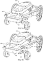
- Figures 6A and 6B each shows a schematic overview of a robotic lawnmower 100 according to one embodiment of the teachings of this application, wherein the beam axle 145 is covered by the chassis 140 (for example by a cover of the chassis 140).
- the chassis (or the cover of the chassis, which is to be considered as being a part of the chassis for the purpose of this application) has two openings 149 through which the beam axle 145 protrudes. This allows for the beam axle to be covered by the chassis to protect the beam axle 145 and the pivot point from environmental factors such as dirt and water. To offer more protection the opening(s) 149 may be covered for example by a rubber or cloth gaiter.
- the openings 149 allows the beam axle to be displaced a certain amount.
- the displacement needed depends on the overall design of the robotic lawnmower but in one embodiment the maximum displacement is 15 mm.
- the displacement is usually in the range of 10 to 25 mm.
- the limited displacement of the beam axle prevents the cutting tool 160 (or other work tool) to hit the ground as the chassis 140 of the robotic lawnmower 100 tilts when a front wheel encounters a hole.
- the limited displacement will then allow the beam axle to carry the front wheel 135 through the hole without the robotic lawnmower 100 tilting too much, the beam axle stabilizing the chassis 140 of the robotic lawnmower 100.
- the robotic lawnmower 100 will thus be able to operate and move in a stable manner even in surroundings where there are holes.
- the displacement of the beam axle 145 can also be limited by for example stoppers arranged on the chassis 140.
- the stoppers may alternatively be arranged on the beam axle 145 or stoppers may be arranged on both the beam axle and the chassis 140 (or other part of the robotic lawnmower 100).
- the openings 149 act as stoppers. It should be noted that embodiments having openings 149 may also have other stoppers.
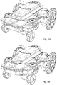
- FIGS 7A and 7B each shows a schematic overview of a robotic lawnmower according to one embodiment of the teachings of this application, wherein a front portion of the chassis 140 is arranged to be able to pivot relative the rest or remainder of the chassis 140.
- the front portion 145 of the chassis 140 effectively forms a beam axle 145. This allows for an alternative manner of sealing any components or circuitry such as sensors or detectors arranged close to the beam axle 145.
Claims (6)
- Système (200) de tondeuse à gazon robotisée comprenant une tondeuse à gazon robotisée (100), ladite tondeuse à gazon robotisée (100) comprenant deux roues avant (130) et un châssis (140), où ladite tondeuse à gazon robotisée est caractérisée en ce que les deux roues avant (130) sont agencées sur un essieu rigide (145) qui est agencé en pivotement sur le châssis (140),
dans lequel l'essieu rigide (145) est fixé de manière pivotante au châssis (140) à travers un point de pivotement (147) qui est un axe (147) faisant saillie à partir du châssis (140) et s'étendant à travers une ouverture (146) dans l'essieu rigide (145),
dans lequel le trou ou l'ouverture (146) est allongé(e) pour permettre un mouvement vertical de l'axe de pivotement (147),et
dans lequel des capteurs sont agencés pour déterminer si la tondeuse à gazon robotisée (100) est soulevée ou non en déterminant dans quelle partie du trou ou de l'ouverture (146) se trouve l'axe de pivotement (147). - Système (200) de tondeuse à gazon robotisée selon la revendication 1, dans lequel ledit essieu rigide (145) est agencé pour équilibrer une roue avant (130A) par rapport à l'autre roue avant (130B).
- Système (200) de tondeuse à gazon robotisée selon la revendication 2, dans lequel ledit essieu rigide (145) est un seul essieu rigide (145) commun aux deux roues avant (130) .
- Système (200) de tondeuse à gazon robotisée selon l'une des revendications précédentes, dans lequel l'outil de travail robotisé (100) comprend en outre une butée (149) pour restreindre un déplacement maximal dudit essieu rigide (145) .
- Système (200) de tondeuse à gazon robotisée selon la revendication 2, dans lequel ladite butée est une ouverture (149) dans le châssis (140) de sorte que le châssis (140) soit agencé pour couvrir le point de pivotement (147).
- Système (200) de tondeuse à gazon robotisée selon l'une des revendications précédentes, dans lequel l'essieu rigide (145) est agencé en tant que partie avant du châssis (140), dans lequel
la partie avant du châssis (140) est agencée en pivotement sur le reste du châssis (140).
Priority Applications (1)
| Application Number | Priority Date | Filing Date | Title |
|---|---|---|---|
| EP20170029.1A EP3699068B1 (fr) | 2014-06-19 | 2014-06-19 | Système de tondeuse à gazon robotique |
Applications Claiming Priority (1)
| Application Number | Priority Date | Filing Date | Title |
|---|---|---|---|
| PCT/EP2014/062915 WO2015192900A1 (fr) | 2014-06-19 | 2014-06-19 | Outil de travail robotique amélioré |
Related Child Applications (1)
| Application Number | Title | Priority Date | Filing Date |
|---|---|---|---|
| EP20170029.1A Division EP3699068B1 (fr) | 2014-06-19 | 2014-06-19 | Système de tondeuse à gazon robotique |
Publications (2)
| Publication Number | Publication Date |
|---|---|
| EP3157803A1 EP3157803A1 (fr) | 2017-04-26 |
| EP3157803B1 true EP3157803B1 (fr) | 2020-05-06 |
Family
ID=51033165
Family Applications (2)
| Application Number | Title | Priority Date | Filing Date |
|---|---|---|---|
| EP20170029.1A Active EP3699068B1 (fr) | 2014-06-19 | 2014-06-19 | Système de tondeuse à gazon robotique |
| EP14734054.1A Active EP3157803B1 (fr) | 2014-06-19 | 2014-06-19 | Outil de travail robotique amélioré |
Family Applications Before (1)
| Application Number | Title | Priority Date | Filing Date |
|---|---|---|---|
| EP20170029.1A Active EP3699068B1 (fr) | 2014-06-19 | 2014-06-19 | Système de tondeuse à gazon robotique |
Country Status (4)
| Country | Link |
|---|---|
| US (1) | US10207557B2 (fr) |
| EP (2) | EP3699068B1 (fr) |
| CN (1) | CN106458273B (fr) |
| WO (1) | WO2015192900A1 (fr) |
Cited By (1)
| Publication number | Priority date | Publication date | Assignee | Title |
|---|---|---|---|---|
| IT202200007133A1 (it) | 2022-04-11 | 2023-10-11 | Stiga S P A In Breve Anche St S P A | “Robot tosaerba con motore di trazione fuori asse” |
Families Citing this family (21)
| Publication number | Priority date | Publication date | Assignee | Title |
|---|---|---|---|---|
| EP3102914B1 (fr) * | 2014-02-03 | 2018-08-08 | Husqvarna AB | Détection d'obstacles pour un outil de travail robotisé |
| GB2539661B (en) | 2015-06-22 | 2019-06-26 | Q Bot Ltd | Robotic Vehicle |
| DK3376848T3 (da) * | 2015-11-17 | 2020-07-13 | Vektor Dynamics As | Robotagtig landbrugskøretøj med sikkerhedsforanstaltninger |
| ITUA20161982A1 (it) * | 2016-03-24 | 2017-09-24 | Fabrizio Bernini | Dispositivo di lavoro semovente |
| ITUA20162403A1 (it) * | 2016-04-07 | 2017-10-07 | Vincenzo Sferruzza | Robot tagliaerba automatico |
| WO2018000922A1 (fr) | 2016-06-30 | 2018-01-04 | Tti (Macao Commercial Offshore) Limited | Tondeuse à gazon autonome et système de navigation associé |
| US11172608B2 (en) | 2016-06-30 | 2021-11-16 | Tti (Macao Commercial Offshore) Limited | Autonomous lawn mower and a system for navigating thereof |
| US20180143634A1 (en) * | 2016-11-22 | 2018-05-24 | Left Hand Robotics, Inc. | Autonomous path treatment systems and methods |
| JP6559112B2 (ja) * | 2016-11-25 | 2019-08-14 | 本田技研工業株式会社 | 作業機 |
| JP6559111B2 (ja) * | 2016-11-25 | 2019-08-14 | 本田技研工業株式会社 | 乗用作業機 |
| SE541243C2 (en) | 2017-02-21 | 2019-05-14 | Husqvarna Ab | Autonomous self-propelled robotic lawnmower comprising cambered wheels |
| SE540585C2 (en) * | 2017-03-23 | 2018-10-02 | Husqvarna Ab | A robotic work tool and a method for use in a robotic work tool comprising a lift/collision detection device |
| US11470773B2 (en) * | 2017-08-02 | 2022-10-18 | Briggs & Stratton, Llc | Stand-on mower with an oscillating front axle |
| US10767383B2 (en) * | 2017-11-07 | 2020-09-08 | Robin Technologies, Inc. | Ground wire guidance system for robotic vehicle with doorway access |
| WO2019197012A1 (fr) * | 2018-04-09 | 2019-10-17 | Vitirover | Élément d'arrêt pour un robot ayant un châssis et un carter d'essieu arrière libre avec deux axes de rotation par rapport au châssis |
| WO2019197013A1 (fr) * | 2018-04-09 | 2019-10-17 | Vitirover | Robot et procédé de commande du robot |
| SE543724C2 (en) * | 2018-10-24 | 2021-06-29 | Husqvarna Ab | Articulated robotic working tool with goniometer arrangement |
| US11066283B2 (en) * | 2018-12-21 | 2021-07-20 | Logistics and Supply Chain MultiTech R&D Centre Limited | Suspension system for an automated guide vehicle |
| SE543737C2 (en) * | 2019-05-28 | 2021-07-06 | Husqvarna Ab | Autonomous robotic lawnmower |
| US11469604B2 (en) | 2019-09-13 | 2022-10-11 | Echo Incorporated | System for facilitating connection between a charging station and a rechargeable power supply on an operating unit |
| AU2020289833A1 (en) * | 2019-12-23 | 2021-07-15 | The Raymond Corporation | Systems and methods for a material handling vehicle with an articulating axle |
Citations (1)
| Publication number | Priority date | Publication date | Assignee | Title |
|---|---|---|---|---|
| EP2687077A2 (fr) * | 2012-07-17 | 2014-01-22 | AL-KO Kober SE | Tondeuse robotisée |
Family Cites Families (35)
| Publication number | Priority date | Publication date | Assignee | Title |
|---|---|---|---|---|
| US3426720A (en) * | 1966-10-10 | 1969-02-11 | Coot Inc | High traction vehicle |
| US3669469A (en) * | 1970-12-28 | 1972-06-13 | Volvo Ab | Articulated vehicle frame |
| SE440733B (sv) * | 1973-12-07 | 1985-08-19 | Sten Ove Hammarstrand | Axelpendlingssystem for terrengfordon |
| US4079955A (en) * | 1976-08-09 | 1978-03-21 | The United States Of America As Represented By The Secretary Of The Army | Locking device |
| SE410838B (sv) * | 1976-10-22 | 1979-11-12 | Mo Och Domsjoe Ab | Anordning for att reducera lutningen hos ett fordons pabyggnad |
| US4533010A (en) * | 1982-12-30 | 1985-08-06 | David Harder | Truck having a front axle oscillatable relative to a rear axle |
| JPS62283072A (ja) * | 1986-05-31 | 1987-12-08 | Shinichiro Yoshimura | 全方位走行車両 |
| US4750751A (en) * | 1986-11-26 | 1988-06-14 | Deere & Company | Pivoting axle for a hillside combine |
| FR2702012B1 (fr) * | 1993-02-25 | 1995-05-24 | Sacmi | Dispositif hydraulique de contrôle des oscillations d'un corps mobile et application au train oscillant d'un véhicule moteur. |
| AUPM932694A0 (en) * | 1994-11-08 | 1994-12-01 | Lendal Pty Ltd | A mobile chassis |
| US5813697A (en) * | 1994-12-05 | 1998-09-29 | Trak International, Inc. | Forklift stabilizing apparatus |
| US5806870A (en) * | 1996-02-05 | 1998-09-15 | Hull; Harold L. | Utility vehicle having two pivotable chassis |
| US5873586A (en) * | 1996-03-04 | 1999-02-23 | Krimmell; John | Rocking beam suspension |
| US6062333A (en) * | 1996-07-27 | 2000-05-16 | Ferris Industries, Inc. | Riding mower with pivoting front wheel assembly |
| US6231061B1 (en) * | 1999-01-13 | 2001-05-15 | Calvin Keith Cope | Vehicle frame assembly and split-frame vehicle |
| AU2632700A (en) * | 1999-02-08 | 2000-08-25 | Toro Company, The | Articulating vehicle |
| ITFI20010021A1 (it) | 2001-02-07 | 2002-08-07 | Zucchetti Ct Sistemi S P A | Apparecchio pulitore aspirante automatico per pavimenti |
| US7400108B2 (en) | 2004-04-15 | 2008-07-15 | University Of Utah Research Foundation | System and method for controlling modular robots |
| US7721832B2 (en) * | 2007-08-01 | 2010-05-25 | Deere & Company | Walking beam suspension |
| CN201217456Y (zh) * | 2008-05-23 | 2009-04-08 | 上海宝冶建设有限公司 | 半挂牵引式废钢料槽运输车的牵引车 |
| US7866671B2 (en) * | 2009-01-12 | 2011-01-11 | Herman Madler | Automatic leveling vehicle |
| TWI654130B (zh) | 2010-12-15 | 2019-03-21 | 辛波提克有限責任公司 | 自主式輸運機器人,用於自主式輸運車輛的懸吊鎖住系統及用於自主式輸運車輛的懸吊系統 |
| US8696010B2 (en) * | 2010-12-15 | 2014-04-15 | Symbotic, LLC | Suspension system for autonomous transports |
| FR2969571B1 (fr) | 2010-12-23 | 2015-01-16 | Thales Sa | Systeme robotise collaborateur |
| FI123820B (fi) * | 2011-02-25 | 2013-11-15 | Ponsse Oyj | Alustarakenne ja järjestely ajoneuvossa tai koneessa |
| KR101931362B1 (ko) | 2011-08-22 | 2018-12-24 | 삼성전자주식회사 | 로봇청소기 및 그 제어방법 |
| CN202400172U (zh) * | 2012-01-12 | 2012-08-29 | 李辉 | 一种木料运输车 |
| CN102700633A (zh) * | 2012-06-11 | 2012-10-03 | 福建福大机械有限公司 | 一种平衡重式后转向叉装车 |
| WO2014007694A1 (fr) | 2012-07-04 | 2014-01-09 | Husqvarna Ab | Étalonnage de hauteur de coupe pour une faucheuse robotique |
| US9491904B2 (en) * | 2012-07-05 | 2016-11-15 | Husqvarna Ab | Modular robotic vehicle |
| CN104470351A (zh) | 2012-07-05 | 2015-03-25 | 胡斯华纳有限公司 | 检测抬起事件和碰撞事件的机器人车的位移传感器 |
| EP3102914B1 (fr) * | 2014-02-03 | 2018-08-08 | Husqvarna AB | Détection d'obstacles pour un outil de travail robotisé |
| EP3133911A1 (fr) * | 2014-04-25 | 2017-03-01 | Husqvarna AB | Outil de travail robotique amélioré |
| SE539760C2 (en) * | 2014-12-23 | 2017-11-21 | Husqvarna Ab | Control of downhill movement for a robotic work tool |
| US9878587B1 (en) * | 2016-10-31 | 2018-01-30 | X Development Llc | Movable base for a robotic system |
-
2014
- 2014-06-19 CN CN201480079822.1A patent/CN106458273B/zh active Active
- 2014-06-19 EP EP20170029.1A patent/EP3699068B1/fr active Active
- 2014-06-19 EP EP14734054.1A patent/EP3157803B1/fr active Active
- 2014-06-19 WO PCT/EP2014/062915 patent/WO2015192900A1/fr active Application Filing
- 2014-06-19 US US15/318,148 patent/US10207557B2/en active Active
Patent Citations (1)
| Publication number | Priority date | Publication date | Assignee | Title |
|---|---|---|---|---|
| EP2687077A2 (fr) * | 2012-07-17 | 2014-01-22 | AL-KO Kober SE | Tondeuse robotisée |
Cited By (2)
| Publication number | Priority date | Publication date | Assignee | Title |
|---|---|---|---|---|
| IT202200007133A1 (it) | 2022-04-11 | 2023-10-11 | Stiga S P A In Breve Anche St S P A | “Robot tosaerba con motore di trazione fuori asse” |
| EP4260676A1 (fr) | 2022-04-11 | 2023-10-18 | Stiga S.p.A. in breve anche St. S.p.A. | Tondeuse à gazon robotisée avec moteur d'entraînement hors axe |
Also Published As
| Publication number | Publication date |
|---|---|
| EP3157803A1 (fr) | 2017-04-26 |
| WO2015192900A1 (fr) | 2015-12-23 |
| EP3699068B1 (fr) | 2021-11-03 |
| CN106458273A (zh) | 2017-02-22 |
| US10207557B2 (en) | 2019-02-19 |
| CN106458273B (zh) | 2019-11-01 |
| US20170129297A1 (en) | 2017-05-11 |
| EP3699068A1 (fr) | 2020-08-26 |
Similar Documents
| Publication | Publication Date | Title |
|---|---|---|
| EP3157803B1 (fr) | Outil de travail robotique amélioré | |
| EP3227169B1 (fr) | Robot de tondeuse à gazon à transmission intégrale | |
| EP3571917B1 (fr) | Tondeuse | |
| EP3236734B1 (fr) | Fonctionnement amélioré d'un outil de travail robotique en adaptant le fonctionnement aux conditions météorologiques | |
| US10031527B2 (en) | Obstacle detection for a robotic working tool | |
| US10440879B2 (en) | Robotic work tool | |
| US20100250024A1 (en) | Fully autonomous or remotely operated golf ball picking system | |
| US11009878B2 (en) | Autonomously navigating vehicle | |
| WO2014007728A1 (fr) | Capteur de déplacement pour un véhicule robotisé, destiné à la détection d'un événement de soulèvement et d'un événement de collision | |
| CN111045423B (zh) | 一种智能四轮驱动uwb定位割草机器人及其控制方法 | |
| JP7061793B2 (ja) | 自律制御型草刈機 | |
| CN110989578A (zh) | 一种可无线控制的双核四轮驱动uwb定位割草机器人及其控制方法 | |
| CN112512299A (zh) | 自主工作器具 | |
| CN111123910B (zh) | 一种双核四轮驱动uwb定位割草机器人及其控制方法 | |
| JP2020025533A (ja) | 自律制御型草刈機 | |
| CN210466134U (zh) | 自动驾驶农机及其动力系统 | |
| WO2014111898A2 (fr) | Machine de traction automatisée | |
| CN211580673U (zh) | 一种单核四轮驱动的割草机器人 | |
| SE2150683A1 (en) | A robotic lawn mower with enhanced cutting properties | |
| US11483967B1 (en) | Method of conversion to automated lawn mower | |
| EP4368005A1 (fr) | Tondeuse à gazon robotique ayant des propriétés de coupe améliorées | |
| CN112799390B (zh) | 自移动设备及其工作方法 | |
| EP3498077B1 (fr) | Dispositif de rangement | |
| EP3953783A1 (fr) | Système et procédé de réception de signal d'outil de travail robotisé | |
| SE2151621A1 (en) | Improved navigation for a robotic work tool system |
Legal Events
| Date | Code | Title | Description |
|---|---|---|---|
| STAA | Information on the status of an ep patent application or granted ep patent |
Free format text: STATUS: THE INTERNATIONAL PUBLICATION HAS BEEN MADE |
|
| PUAI | Public reference made under article 153(3) epc to a published international application that has entered the european phase |
Free format text: ORIGINAL CODE: 0009012 |
|
| STAA | Information on the status of an ep patent application or granted ep patent |
Free format text: STATUS: REQUEST FOR EXAMINATION WAS MADE |
|
| 17P | Request for examination filed |
Effective date: 20161214 |
|
| AK | Designated contracting states |
Kind code of ref document: A1 Designated state(s): AL AT BE BG CH CY CZ DE DK EE ES FI FR GB GR HR HU IE IS IT LI LT LU LV MC MK MT NL NO PL PT RO RS SE SI SK SM TR |
|
| AX | Request for extension of the european patent |
Extension state: BA ME |
|
| DAX | Request for extension of the european patent (deleted) | ||
| STAA | Information on the status of an ep patent application or granted ep patent |
Free format text: STATUS: EXAMINATION IS IN PROGRESS |
|
| 17Q | First examination report despatched |
Effective date: 20180223 |
|
| REG | Reference to a national code |
Ref country code: DE Ref legal event code: R079 Ref document number: 602014064958 Country of ref document: DE Free format text: PREVIOUS MAIN CLASS: B62D0053020000 Ipc: A01D0034000000 |
|
| GRAP | Despatch of communication of intention to grant a patent |
Free format text: ORIGINAL CODE: EPIDOSNIGR1 |
|
| STAA | Information on the status of an ep patent application or granted ep patent |
Free format text: STATUS: GRANT OF PATENT IS INTENDED |
|
| RIC1 | Information provided on ipc code assigned before grant |
Ipc: A01D 34/00 20060101AFI20191213BHEP Ipc: B62D 53/02 20060101ALI20191213BHEP |
|
| INTG | Intention to grant announced |
Effective date: 20200116 |
|
| GRAS | Grant fee paid |
Free format text: ORIGINAL CODE: EPIDOSNIGR3 |
|
| GRAA | (expected) grant |
Free format text: ORIGINAL CODE: 0009210 |
|
| STAA | Information on the status of an ep patent application or granted ep patent |
Free format text: STATUS: THE PATENT HAS BEEN GRANTED |
|
| AK | Designated contracting states |
Kind code of ref document: B1 Designated state(s): AL AT BE BG CH CY CZ DE DK EE ES FI FR GB GR HR HU IE IS IT LI LT LU LV MC MK MT NL NO PL PT RO RS SE SI SK SM TR |
|
| REG | Reference to a national code |
Ref country code: GB Ref legal event code: FG4D |
|
| REG | Reference to a national code |
Ref country code: CH Ref legal event code: EP Ref country code: AT Ref legal event code: REF Ref document number: 1265322 Country of ref document: AT Kind code of ref document: T Effective date: 20200515 |
|
| REG | Reference to a national code |
Ref country code: IE Ref legal event code: FG4D |
|
| REG | Reference to a national code |
Ref country code: DE Ref legal event code: R096 Ref document number: 602014064958 Country of ref document: DE |
|
| REG | Reference to a national code |
Ref country code: SE Ref legal event code: TRGR |
|
| REG | Reference to a national code |
Ref country code: LT Ref legal event code: MG4D |
|
| REG | Reference to a national code |
Ref country code: NL Ref legal event code: MP Effective date: 20200506 |
|
| PG25 | Lapsed in a contracting state [announced via postgrant information from national office to epo] |
Ref country code: LT Free format text: LAPSE BECAUSE OF FAILURE TO SUBMIT A TRANSLATION OF THE DESCRIPTION OR TO PAY THE FEE WITHIN THE PRESCRIBED TIME-LIMIT Effective date: 20200506 Ref country code: FI Free format text: LAPSE BECAUSE OF FAILURE TO SUBMIT A TRANSLATION OF THE DESCRIPTION OR TO PAY THE FEE WITHIN THE PRESCRIBED TIME-LIMIT Effective date: 20200506 Ref country code: NO Free format text: LAPSE BECAUSE OF FAILURE TO SUBMIT A TRANSLATION OF THE DESCRIPTION OR TO PAY THE FEE WITHIN THE PRESCRIBED TIME-LIMIT Effective date: 20200806 Ref country code: GR Free format text: LAPSE BECAUSE OF FAILURE TO SUBMIT A TRANSLATION OF THE DESCRIPTION OR TO PAY THE FEE WITHIN THE PRESCRIBED TIME-LIMIT Effective date: 20200807 Ref country code: IS Free format text: LAPSE BECAUSE OF FAILURE TO SUBMIT A TRANSLATION OF THE DESCRIPTION OR TO PAY THE FEE WITHIN THE PRESCRIBED TIME-LIMIT Effective date: 20200906 Ref country code: PT Free format text: LAPSE BECAUSE OF FAILURE TO SUBMIT A TRANSLATION OF THE DESCRIPTION OR TO PAY THE FEE WITHIN THE PRESCRIBED TIME-LIMIT Effective date: 20200907 |
|
| PG25 | Lapsed in a contracting state [announced via postgrant information from national office to epo] |
Ref country code: HR Free format text: LAPSE BECAUSE OF FAILURE TO SUBMIT A TRANSLATION OF THE DESCRIPTION OR TO PAY THE FEE WITHIN THE PRESCRIBED TIME-LIMIT Effective date: 20200506 Ref country code: RS Free format text: LAPSE BECAUSE OF FAILURE TO SUBMIT A TRANSLATION OF THE DESCRIPTION OR TO PAY THE FEE WITHIN THE PRESCRIBED TIME-LIMIT Effective date: 20200506 Ref country code: LV Free format text: LAPSE BECAUSE OF FAILURE TO SUBMIT A TRANSLATION OF THE DESCRIPTION OR TO PAY THE FEE WITHIN THE PRESCRIBED TIME-LIMIT Effective date: 20200506 Ref country code: BG Free format text: LAPSE BECAUSE OF FAILURE TO SUBMIT A TRANSLATION OF THE DESCRIPTION OR TO PAY THE FEE WITHIN THE PRESCRIBED TIME-LIMIT Effective date: 20200806 |
|
| PG25 | Lapsed in a contracting state [announced via postgrant information from national office to epo] |
Ref country code: NL Free format text: LAPSE BECAUSE OF FAILURE TO SUBMIT A TRANSLATION OF THE DESCRIPTION OR TO PAY THE FEE WITHIN THE PRESCRIBED TIME-LIMIT Effective date: 20200506 Ref country code: AL Free format text: LAPSE BECAUSE OF FAILURE TO SUBMIT A TRANSLATION OF THE DESCRIPTION OR TO PAY THE FEE WITHIN THE PRESCRIBED TIME-LIMIT Effective date: 20200506 |
|
| REG | Reference to a national code |
Ref country code: AT Ref legal event code: UEP Ref document number: 1265322 Country of ref document: AT Kind code of ref document: T Effective date: 20200506 |
|
| PG25 | Lapsed in a contracting state [announced via postgrant information from national office to epo] |
Ref country code: IT Free format text: LAPSE BECAUSE OF FAILURE TO SUBMIT A TRANSLATION OF THE DESCRIPTION OR TO PAY THE FEE WITHIN THE PRESCRIBED TIME-LIMIT Effective date: 20200506 Ref country code: DK Free format text: LAPSE BECAUSE OF FAILURE TO SUBMIT A TRANSLATION OF THE DESCRIPTION OR TO PAY THE FEE WITHIN THE PRESCRIBED TIME-LIMIT Effective date: 20200506 Ref country code: EE Free format text: LAPSE BECAUSE OF FAILURE TO SUBMIT A TRANSLATION OF THE DESCRIPTION OR TO PAY THE FEE WITHIN THE PRESCRIBED TIME-LIMIT Effective date: 20200506 Ref country code: SM Free format text: LAPSE BECAUSE OF FAILURE TO SUBMIT A TRANSLATION OF THE DESCRIPTION OR TO PAY THE FEE WITHIN THE PRESCRIBED TIME-LIMIT Effective date: 20200506 Ref country code: RO Free format text: LAPSE BECAUSE OF FAILURE TO SUBMIT A TRANSLATION OF THE DESCRIPTION OR TO PAY THE FEE WITHIN THE PRESCRIBED TIME-LIMIT Effective date: 20200506 Ref country code: ES Free format text: LAPSE BECAUSE OF FAILURE TO SUBMIT A TRANSLATION OF THE DESCRIPTION OR TO PAY THE FEE WITHIN THE PRESCRIBED TIME-LIMIT Effective date: 20200506 Ref country code: CZ Free format text: LAPSE BECAUSE OF FAILURE TO SUBMIT A TRANSLATION OF THE DESCRIPTION OR TO PAY THE FEE WITHIN THE PRESCRIBED TIME-LIMIT Effective date: 20200506 |
|
| REG | Reference to a national code |
Ref country code: CH Ref legal event code: PL |
|
| REG | Reference to a national code |
Ref country code: DE Ref legal event code: R097 Ref document number: 602014064958 Country of ref document: DE |
|
| PG25 | Lapsed in a contracting state [announced via postgrant information from national office to epo] |
Ref country code: MC Free format text: LAPSE BECAUSE OF FAILURE TO SUBMIT A TRANSLATION OF THE DESCRIPTION OR TO PAY THE FEE WITHIN THE PRESCRIBED TIME-LIMIT Effective date: 20200506 Ref country code: PL Free format text: LAPSE BECAUSE OF FAILURE TO SUBMIT A TRANSLATION OF THE DESCRIPTION OR TO PAY THE FEE WITHIN THE PRESCRIBED TIME-LIMIT Effective date: 20200506 Ref country code: SK Free format text: LAPSE BECAUSE OF FAILURE TO SUBMIT A TRANSLATION OF THE DESCRIPTION OR TO PAY THE FEE WITHIN THE PRESCRIBED TIME-LIMIT Effective date: 20200506 |
|
| PLBE | No opposition filed within time limit |
Free format text: ORIGINAL CODE: 0009261 |
|
| STAA | Information on the status of an ep patent application or granted ep patent |
Free format text: STATUS: NO OPPOSITION FILED WITHIN TIME LIMIT |
|
| PG25 | Lapsed in a contracting state [announced via postgrant information from national office to epo] |
Ref country code: LU Free format text: LAPSE BECAUSE OF NON-PAYMENT OF DUE FEES Effective date: 20200619 |
|
| 26N | No opposition filed |
Effective date: 20210209 |
|
| REG | Reference to a national code |
Ref country code: BE Ref legal event code: MM Effective date: 20200630 |
|
| GBPC | Gb: european patent ceased through non-payment of renewal fee |
Effective date: 20200806 |
|
| PG25 | Lapsed in a contracting state [announced via postgrant information from national office to epo] |
Ref country code: CH Free format text: LAPSE BECAUSE OF NON-PAYMENT OF DUE FEES Effective date: 20200630 Ref country code: LI Free format text: LAPSE BECAUSE OF NON-PAYMENT OF DUE FEES Effective date: 20200630 Ref country code: IE Free format text: LAPSE BECAUSE OF NON-PAYMENT OF DUE FEES Effective date: 20200619 |
|
| PG25 | Lapsed in a contracting state [announced via postgrant information from national office to epo] |
Ref country code: BE Free format text: LAPSE BECAUSE OF NON-PAYMENT OF DUE FEES Effective date: 20200630 Ref country code: SI Free format text: LAPSE BECAUSE OF FAILURE TO SUBMIT A TRANSLATION OF THE DESCRIPTION OR TO PAY THE FEE WITHIN THE PRESCRIBED TIME-LIMIT Effective date: 20200506 |
|
| PG25 | Lapsed in a contracting state [announced via postgrant information from national office to epo] |
Ref country code: GB Free format text: LAPSE BECAUSE OF NON-PAYMENT OF DUE FEES Effective date: 20200806 |
|
| PG25 | Lapsed in a contracting state [announced via postgrant information from national office to epo] |
Ref country code: TR Free format text: LAPSE BECAUSE OF FAILURE TO SUBMIT A TRANSLATION OF THE DESCRIPTION OR TO PAY THE FEE WITHIN THE PRESCRIBED TIME-LIMIT Effective date: 20200506 Ref country code: MT Free format text: LAPSE BECAUSE OF FAILURE TO SUBMIT A TRANSLATION OF THE DESCRIPTION OR TO PAY THE FEE WITHIN THE PRESCRIBED TIME-LIMIT Effective date: 20200506 Ref country code: CY Free format text: LAPSE BECAUSE OF FAILURE TO SUBMIT A TRANSLATION OF THE DESCRIPTION OR TO PAY THE FEE WITHIN THE PRESCRIBED TIME-LIMIT Effective date: 20200506 |
|
| PG25 | Lapsed in a contracting state [announced via postgrant information from national office to epo] |
Ref country code: MK Free format text: LAPSE BECAUSE OF FAILURE TO SUBMIT A TRANSLATION OF THE DESCRIPTION OR TO PAY THE FEE WITHIN THE PRESCRIBED TIME-LIMIT Effective date: 20200506 |
|
| P01 | Opt-out of the competence of the unified patent court (upc) registered |
Effective date: 20230419 |
|
| PGFP | Annual fee paid to national office [announced via postgrant information from national office to epo] |
Ref country code: FR Payment date: 20230522 Year of fee payment: 10 Ref country code: DE Payment date: 20230508 Year of fee payment: 10 |
|
| PGFP | Annual fee paid to national office [announced via postgrant information from national office to epo] |
Ref country code: SE Payment date: 20230505 Year of fee payment: 10 Ref country code: AT Payment date: 20230508 Year of fee payment: 10 |