EP3157641B1 - Wet fire protection systems and methods for storage - Google Patents
Wet fire protection systems and methods for storage Download PDFInfo
- Publication number
- EP3157641B1 EP3157641B1 EP15736710.3A EP15736710A EP3157641B1 EP 3157641 B1 EP3157641 B1 EP 3157641B1 EP 15736710 A EP15736710 A EP 15736710A EP 3157641 B1 EP3157641 B1 EP 3157641B1
- Authority
- EP
- European Patent Office
- Prior art keywords
- fluid distribution
- fire
- distribution devices
- detectors
- fluid
- Prior art date
- Legal status (The legal status is an assumption and is not a legal conclusion. Google has not performed a legal analysis and makes no representation as to the accuracy of the status listed.)
- Active
Links
Images



Classifications
-
- A—HUMAN NECESSITIES
- A62—LIFE-SAVING; FIRE-FIGHTING
- A62C—FIRE-FIGHTING
- A62C3/00—Fire prevention, containment or extinguishing specially adapted for particular objects or places
- A62C3/002—Fire prevention, containment or extinguishing specially adapted for particular objects or places for warehouses, storage areas or other installations for storing goods
-
- A—HUMAN NECESSITIES
- A62—LIFE-SAVING; FIRE-FIGHTING
- A62C—FIRE-FIGHTING
- A62C3/00—Fire prevention, containment or extinguishing specially adapted for particular objects or places
-
- A—HUMAN NECESSITIES
- A62—LIFE-SAVING; FIRE-FIGHTING
- A62C—FIRE-FIGHTING
- A62C31/00—Delivery of fire-extinguishing material
- A62C31/02—Nozzles specially adapted for fire-extinguishing
-
- A—HUMAN NECESSITIES
- A62—LIFE-SAVING; FIRE-FIGHTING
- A62C—FIRE-FIGHTING
- A62C35/00—Permanently-installed equipment
- A62C35/58—Pipe-line systems
-
- A—HUMAN NECESSITIES
- A62—LIFE-SAVING; FIRE-FIGHTING
- A62C—FIRE-FIGHTING
- A62C35/00—Permanently-installed equipment
- A62C35/58—Pipe-line systems
- A62C35/60—Pipe-line systems wet, i.e. containing extinguishing material even when not in use
-
- A—HUMAN NECESSITIES
- A62—LIFE-SAVING; FIRE-FIGHTING
- A62C—FIRE-FIGHTING
- A62C37/00—Control of fire-fighting equipment
- A62C37/36—Control of fire-fighting equipment an actuating signal being generated by a sensor separate from an outlet device
-
- A—HUMAN NECESSITIES
- A62—LIFE-SAVING; FIRE-FIGHTING
- A62C—FIRE-FIGHTING
- A62C37/00—Control of fire-fighting equipment
- A62C37/36—Control of fire-fighting equipment an actuating signal being generated by a sensor separate from an outlet device
- A62C37/38—Control of fire-fighting equipment an actuating signal being generated by a sensor separate from an outlet device by both sensor and actuator, e.g. valve, being in the danger zone
- A62C37/40—Control of fire-fighting equipment an actuating signal being generated by a sensor separate from an outlet device by both sensor and actuator, e.g. valve, being in the danger zone with electric connection between sensor and actuator
-
- A—HUMAN NECESSITIES
- A62—LIFE-SAVING; FIRE-FIGHTING
- A62C—FIRE-FIGHTING
- A62C99/00—Subject matter not provided for in other groups of this subclass
- A62C99/0009—Methods of extinguishing or preventing the spread of fire by cooling down or suffocating the flames
- A62C99/0072—Methods of extinguishing or preventing the spread of fire by cooling down or suffocating the flames using sprayed or atomised water
Definitions
- the present invention relates generally to fire protection systems for storage. More specifically, the present invention involves fire protection systems for storage arrangements having a reduced hydraulic demand for comparable sized storage arrangements.
- NFPA 13 Standard for the Installation of Sprinkler Systems (2013 ed.)
- Chapters 11-12 define standardized hydraulic design approaches for systems designed and installed with "automatic” storage sprinklers, such as for example, standard spray, control mode specific application (CMSA), extended coverage or early suppression fast response (ESFR).
- CMSA standard spray, control mode specific application
- ESFR early suppression fast response
- NFPA 13 defines "automatic sprinklers” as "a fire suppression or control device that operates automatically when its heat-activated element is heated to its thermal rating or above, allowing water to discharge over a specified area.”
- a “hydraulically designed system” is a calculated system in which pipe sizes are selected on a pressure loss basis to provide a prescribed water density, in gallons per minute per square foot, or a prescribed minimum discharge pressure or flow per sprinkler, distributed with a reasonable degree of uniformity over a specified area.
- the standards specify the hydraulic design area or sprinkler operational area, the density (GPM/SQ. FT) requirements, and/or minimum operating pressures for a given storage commodity and arrangement.
- a “hydraulic design area” is an area, defined in square units of measure, comprising a defined number of hydraulically remote sprinklers at a defined spacing between each sprinkler.
- Hydraulicically remote sprinklers are sprinklers that place the greatest water demand on a system in order to provide a prescribed minimum discharge pressure or flow. It is understood by those skilled in the art that the hydraulically remote sprinklers may or may not be physically located the furthest from the fluid the water supply providing the prescribed minimum pressure or flow.
- Section 21 of NFPA 13 provides for special approaches that permit hydraulic designs other than those specified under Chapters 11-20.
- the hydraulic design area can be defined by a number of design sprinklers as derived from worst-case results obtained from full-scale fire testing.
- the special design approaches of NFPA still include minimum design requirements.
- Section 21.1.8.1 requires that the number of design sprinklers defining the hydraulic demand be no less than: (i) twelve sprinklers for standard coverage sprinklers; (ii) eight sprinklers for extended coverage sprinklers on 3.66m ⁇ 3.66m (12 ft.
- Section 21.1.8.2 provides that the minimum operating area based on the sprinkler-to-sprinkler spacing of the given number of design sprinklers shall be no less than 71.3m 2 (768 square feet).
- Other industry accepted standards for example standards under FM Global (FM), define the number of design sprinklers for use in sprinkler systems for a storage occupancy based upon sprinkler orifice size, orientation, RTI (thermal response), spacing, and minimum operating pressure.
- the number of sprinklers is determined by a fire test in which an appropriate safety factor is assessed on the total number of sprinklers that operate, such as for example, a 50% safety factor.
- the safety factor is designed to account for uncertainty in the operation sequence inherent to thermo-mechanically operated automatic sprinkler systems due to things such as sprinkler skipping, fire chasing, etc.
- the hydraulic designs and demand of the system define the water supply requirements of the system and the economic burden to fulfill those requirements, such as for example, by supplying the appropriate number and size of pump, piping or other fluid distribution equipment to meet the hydraulic designs. Accordingly, there is a desired balance between fulfilling a level of hydraulic demand and the economic burden to supply that demand in order to provide a desired level of fire protection.
- the installation standards also include location requirements for the automatic sprinklers.
- Automatic sprinklers are located above the stored commodity at or near the ceiling of the occupancy in order that its heat-activated element can be activated by the air/gases heated by a fire in the occupancy.
- Section 8.12.4 of NFPA 13 also includes "distance below ceiling” requirements to locate the deflector of the automatic sprinkler below the ceiling of the storage occupancy. According to the standards, a deflector of a pendent sprinkler is to be located at a maximum of 45.72cm (18 inches) from the ceiling.
- the construction of the storage occupancy can present obstructions to the spray pattern of a sprinkler
- obstructions can include for example, beams, ducts, lights, trusses or bar joists at or near the ceiling.
- the installation standards provide for obstruction standards.
- Section 8.12.5 of NFPA 13 includes obstruction rules or requirements for Early Suppression Fast-Response Sprinklers to ensure that the sprinkler and its spray are clear of obstructions at or near the ceiling.
- the obstruction standards provide for a maximum allowable distance of the deflector above the bottom of the obstruction based upon the distance of the sprinkler from the side of the obstruction. Accordingly, both the structure of the automatic sprinkler and the existing installation standards can limit or restrict the ability to install a sprinkler above a stored commodity at increased distances from the ceiling which can add a burden to installing a system to provide a desired level of fire protection.
- a fire protection system for protection of a storage occupancy having a ceiling defining a nominal ceiling height, the system comprising:
- a method of fire protection of a storage occupancy having a nominal ceiling height of thirty feet or greater comprising:
- the Disclosure of the Invention and the preferred systems and methods described herein address the limitations of fire protection systems using automatic fire protections sprinklers under known design criteria, it be to be understood that the preferred systems and method can provide for storage fire protection using controlled actuated fluid distribution devices in systems of any desired hydraulic demand.
- the Disclosure of the Invention is provided as a general introduction to some embodiments of the invention, and is not intended to be limiting to any particular configuration or system. It is to be understood that various features described in the claims can be combined in any suitable way to form any number of embodiments of the invention. Some additional example embodiments including variations and alternative configurations are provided herein.
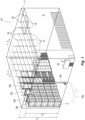
- FIG. 1 Shown in FIG. 1 is a preferred embodiment of a fire protection system 100 for the protection of a storage occupancy 10 and one or more stored commodities 12.
- the preferred systems and methods provide fire protection of a storage occupancy by: (i) sensing a fire; (ii) measuring the fire including its location and size; (iii) analyzing the fire; (iv) responding to the fire with controlled actuation of one or more selectively identified fire protection devices; and (v) terminating the threat from the fire by effectively addressing the fire.
- the preferred systems can effectively address the fire with any one of fire control, fire suppression, extinguishment or a combination thereof.
- fire suppression for storage protection is sharply reducing the heat release rate of a fire and preventing its regrowth by means of direct and sufficient application of a flow of water through the fire plume to the burning fuel surface.
- fire control is defined as limiting the size of a fire by distribution of a flow of water so as to decrease the heat release rate and pre-wet adjacent combustibles, while controlling ceiling gas temperatures to avoid structural damage.
- the preferred systems described herein include a fluid distribution sub-system 100a, a control sub-system 100b and a detection sub-system 100c.
- the detection and control sub-systems work together, preferably by communication of one or more detection signals DS, to sense, measure and analyze a fire.
- the control and fluid distribution sub-systems 100a, 100b work together, preferably by communication of one or more control signals CS, to target and timely deliver a volumetric flow V of firefighting fluid preferably substantially above and about the site of the fire in order to effectively address the fire.
- the volumetric flow V can be defined by one, or more preferably a collection, of distributed discharges Va, Vb, Vc, and Vd.
- the time at which the volumetric flow V of firefighting fluid is released is preferably determined so as to minimize the overall hydraulic demand on the system yet be sufficient to effectively address the size of the fire at the time of delivery.
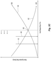
- Shown in FIG. 2C is a comparative graph 400 of heat release versus water application to show the preferred time of controlled actuation of the preferred system 100 as compared to known systems using independently actuated thermally responsive automatic sprinklers, such as for example, systems using early suppression fast response (ESFR) automatic sprinklers.
- the graph 400 shows a first curve 402 showing the actual delivery density (ADD) of water (in flow per area of application, e.g., gallons per minute per square foot (GPM/SQ.
- ADD actual delivery density
- a second curve 404 shows the required delivery density (RDD) of water required to be delivered to the stored commodity at the commodity in order to provide fire suppression by water delivered at a minimum density.
- RDD required delivery density
- the intersection of the ADD and RDD curves defines a time or moment 406 of heat release in the fire in which ADD and RDD are equal to one another. It is believed that any moment in the fire heat release or growth before (or to the left) of the intersection 406 of ADD and RDD can provide for fire suppression performance because the ADD is greater than the RDD.
- line 408 graphically shows a moment of early suppression with an early suppression fast response (ESFR) fire protection sprinkler using only automatic thermal response.
- ESFR early suppression fast response
- the preferred system 100 can provide for a controlled actuation, the preferred system 100 can provide for system response to a fire that is earlier than known ESFR systems. More specifically, the preferred control and detection sub-systems 100b, 100c function to detect a fire preferably in its initial or incipient stages. The control and fluid distribution sub-systems 100a, 100b operate thereafter to address the fire preferably in its incipient stages. Line 410 shows a preferred time in the fire growth or heat release that is earlier than know ESFR system responses (line 408) at which the preferred system 100 is operated to address and more preferably suppress the fire.
- the water demand of the system 100 is reduced as compared to known systems because the moment of controlled response defines an RDD that is smaller than the RDD of known suppression systems responding with only an automatic thermal response. It should be understood that the controlled system response of the system 100 can be controlled to alternatively provide for either standard response or early response to effectively address the fire.
- the preferred system 100 includes a plurality of fluid distribution devices 110, a plurality of detectors 130 and a centralized controller 120 for communication with each of the fluid distribution devices 110 and detectors 130.
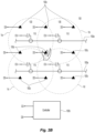
- a preferred embodiment of the fluid distribution device 110 includes a fluid deflecting member 110w coupled to a frame body 110x as schematically shown in FIGS. 3A and 3B and arranged for controlled actuation in manner described herein.
- the frame body 110x includes an inlet for connection to the piping network and an outlet with an internal passageway extending between the inlet and the outlet.
- the deflecting member 110w is preferably axially spaced from the outlet in a fixed spaced relation.
- Water or other firefighting fluid delivered to the inlet is discharged from the outlet to impact the deflecting member 110w and generate a volumetric flow of fluid to effectively address a fire in a manner as described herein.
- the deflecting member can translate with respect to the outlet provided it distributes the firefighting fluid in a desired manner upon operation.
- the deflector or deflecting member can be oriented horizontal with respect to the commodity or otherwise oriented, for example, in an upright orientation relative to the frame body and its outlet.
- the fluid distribution device 110 can be structurally embodied with a frame body and deflector member of an "automatic fire protection sprinkler" as understood in the art and appropriately configured or modified for controlled actuation as described herein.
- This configuration can include the frame body and deflector of known automatic fire protection sprinklers with modifications described herein.
- the frame body and deflectors components for use in the preferred systems and methods can include the components of known automatic sprinklers that have been tested and found by industry accepted organizations to be acceptable for a specified sprinkler performance, such as for example, standard spray, suppression, or extended coverage and equivalents thereof.
- Alternate embodiments of the fluid distribution devices 110 for use in the system 100 include nozzles, misting devices or any other devices configured for controlled operation to distribute a volumetric flow of firefighting fluid in a manner described herein.
- the fluid distribution devices 110 of the preferred system 100 are interconnected by the fluid distribution sub-system 100a.
- the fluid distribution sub-system includes a network of pipes 150 preferably having one or more main pipes 150a from which one or more branch lines 150b, 150c, 150d extend.
- the preferred fluid distribution devices 110 are mounted or connected to the branch lines 150b, 150c, 150d.
- a branch line can define the device spacing a along a single branch line and the device spacing b between branch lines.
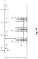
- the fluid distribution devices 110 are installed beneath a ceiling C of a storage occupancy, such as for example, a warehouse above a storage commodity 12. As shown in FIG. 1A and FIGS.
- the deflector 110w can be located below the ceiling C and above the stored commodity 12 to define a preferred deflector position at a preferred desired-to-ceiling distance S.
- the distribution 'devices 110 are preferably mounted to and spaced along the spaced-apart branch pipes 150b, 150c, 150d to form a desired device-to-device spacing a (along branch lines) x b (between branch lines) as seen in FIG. 1 .
- the device-to-device spacing is preferably 2.43m ⁇ 2.43m (8 ft. ⁇ 8 ft.); 3.05m ⁇ 3.05m (10 ft. ⁇ 10 ft.); 3.66m ⁇ 3.66m (12 ft. ⁇ 12 ft.); 4.27m ⁇ 4.27m (14 ft. ⁇ 14 ft.) or any combination thereof.
- the hydraulic demand can be directly related to the area of device operation over which a number of identified devices are controlled and operated to effectively address the fire in a manner as described herein. Accordingly, in a preferred aspect of the system 100, the spacing of the fluid distribution devices 110 defines the hydraulic demand of the system.
- the operation of the fluid distribution devices 110 in the preferred system 100 is not directly or independently triggered or actuated by a thermal or heat-activated response to a fire as in known "automatic sprinklers". Instead, the actuation of the fluid distribution devices 110 is controlled by the preferred controller 120 of the preferred control sub-system 100b. More specifically, the fluid distribution devices 110 are coupled directly or indirectly with the controller 120 to operate a select number of identified devices for distribution of a preferably fixed volumetric flow of fluid to effectively address the fire.
- the hydraulic demand can be controlled and therefore preferably minimized in a manner described herein. More particularly, the preferred system 100 provides for a controlled response to a fire by selecting the number and location of the devices 110 to define an area of operation above and disposed about the fire, in addition to controlling the time of actuation of the selected sprinklers to effectively address the fire.
- the hydraulic demand of the system 100 is preferably minimized. It is believed that the preferred controlled operation of the system 100 can provide for a hydraulic demand that is smaller than known system designs using automatic fire protection sprinklers of comparable flow and distribution characteristics configured to protect the same occupancy.
- the preferred storage fire protection system 100 and its demand is preferably hydraulically designed with a hydraulic design area A or area of device operation being less than about about 71.35m 2 (768 square feet), preferably less than 69.68m 2 (750 square feet); more preferably less than 65.03m 2 (700 square feet); and even more preferably equal to or less than about 53.51m 2 (576 square feet).
- a hydraulic design area A is an area, defined in square units of measure, comprising a defined number of hydraulically remote fluid distribution devices at a defined spacing between each device.
- Hydraulic design area A is an area, defined in square units of measure, comprising a defined number of hydraulically remote fluid distribution devices at a defined spacing between each device.
- Hydraulic design area A is an area, defined in square units of measure, comprising a defined number of hydraulically remote fluid distribution devices at a defined spacing between each device.
- Hydraulic design area A is an area, defined in square units of measure, comprising a defined number of hydraulically remote fluid distribution devices at a defined
- the hydraulic design area A is preferably defined by four hydraulically remote devices and the spacing therebetween.
- the preferred four hydraulically remote devices include two devices per branch lines on two branch lines with a device-to-device spacing of 3.05m (eight feet (8 ft.)) along and between the two branch lines to define a hydraulic design area that is preferably 23.78m 2 (256 square feet).
- the device-to-device spacing can be varied to be any one of 3.05m (ten feet (10 ft.)) or 3.66m (twelve feet (12 ft.)) to respectively define hydraulic design areas A being any one of 37.16m 2 (400 square feet) or 53.51m 2 (576 square feet).
- the hydraulic design area A is defined by nine (9) hydraulically remote fluid distribution devices with three devices per branch line on three branch lines with a device-to-device spacing of 2.43m (eight feet (8 ft.)) along and between the three branch lines to define a hydraulic design area A of 53.51m 2 (576 square feet).
- the preferred system 100 can be hydraulically designed with a hydraulic design area that is smaller than currently available under the known installation standards.
- the hydraulic demand of the system 100 is preferably defined by a number of design fluid distribution device being less than twelve and having at least four, preferably having eleven or fewer and more preferably ranging from eight to six and more preferably ranging from six to four.
- the devices 110 defining the preferably minimized hydraulic design area A or preferred minimum design devices provide a prescribed volumetric flow at a minimum fluid pressure sufficient to address a fire of a particular size or a fire of a particular hazard.
- the fluid distribution devices 110 in the system 100 are provided with a preferred minimum operating pressure range that can effectively address a worst-case scenario test fire with any one of fire control, fire suppression or a combination thereof when the operating pressure is provided to the fluid distribution devices defining a test operational area that is configured as one of the preferred hydraulic design areas A as previously described.
- a preferred controlled actuated system and its fluid distribution devices can be installed in a test-fire setup for a controlled actuation to define a desired test operational area that effectively addresses a test fire of a particular test commodity or hazard with a given test pressure.
- the system 100 can be preferably hydraulically designed with a minimum hydraulic design area equal to the test operational area and with a minimum design pressure equal to the test pressure to protect a hazard equal to or less than the test hazard.
- An exemplary test-fire setup is described below.
- hydraulic design parameters including the preferred minimum number of design fluid distribution devices and a minimum operation pressure can be provided for use in the preferred controlled actuated system 100 for protection of a storage occupancy.
- the hydraulic demand of the system 100 is preferably minimized. It is believed that the preferred controlled operation of the system 100 can provide for a hydraulic demand that is smaller than known system designs using automatic fire protection sprinklers configured to protect the same occupancy.
- the hydraulic demand of the system 100 is preferably defined by a number of design fluid distribution devices being less than twelve, eleven or fewer and more preferably ranging from eight to six and more preferably ranging from six to four.
- Fluid distribution device 110 in the preferred systems and methods can include frame bodies and or deflector members of standard spray sprinklers, suppression sprinklers or extended coverage sprinklers and equivalents thereof which are suitable for use in storage applications.
- U.S. Patent No. 8,176,988 shows an exemplary fire protection sprinkler frame and deflector for use in the systems described herein.
- ESFR early suppression fast response sprinkler
- the sprinkler shown in U.S. Patent No. 8,176,988 is a pendent-type sprinkler; however upright-type sprinklers can be configured for use in the systems described herein.
- sprinklers for configuration and use in the described systems herein include ESFR pendent sprinklers having a nominal K-factor of 362.88 litres/min/bar1 ⁇ 2 (25.2 GPM/(PSI) 1 ⁇ 2 ).
- a preferred fluid distribution device 110 for installation in the system 100 includes the frame body and deflector of the Model ESFR-25 Early Suppression, Fast Response Pendent Sprinkler from TYCO FIRE PRODUCTS, LP of Lansdale, PA having a nominal 25.2 K-factor ESFR.
- the preferred frame body and deflector member is shown in Tyco Fire Products, LP technical data sheet, TFP312 entitled, " Model ESFR-25, Early Suppression Fast Response Pendent Sprinklers 25.2 K-factor" (Nov.
- the K-factor is defined as a constant representing the discharge coefficient that is quantified by the flow of fluid in gallons per minute (GPM) from the outlet of the frame body divided by the square root of the pressure of the flow of fluid fed into the inlet of the frame passageway in pounds per square inch (PSI).
- the K-factor is expressed as litres/min/bar1 ⁇ 2 (GPM/(PSI) 1 ⁇ 2 ).
- a rated or nominal K- factor or rated discharge coefficient of a sprinkler as a mean value over a K-factor range.
- NFPA 13 provides the following nominal K-factors (with the K-factor range shown in parenthesis): (i) 161.28 (154.08-168.84) litres/min/Bar 1/2 (11.2 (10.7-11.7) GPM/(PSI) 1 ⁇ 2 ); (ii) 201.6 (194.4-208.8) litres/min/Bar 1/2 (14.0 (13.5-14.5) GPM/(PSI) 1/2 ); (iii) 483.84 (457.92-501.12) litres/min/Bar 1/2 (16.8 (16.0-17.6) GPM/(PSI) 1/2 ); (iv) 282.24 (267.84-296.64) litres/min/Bar 1/2 (19.6 (18.6-20.6) GPM/(PSI) 1/2 ); (v) 322.56 (306.72-338.40) litres/min/Bar 1/2 (22.4 (21.3-23.5) GPM/(PSI) 1/2 ); (vi) 362.88 (344.16-381.60)
- FIGS. 3A and 3B are schematic representations of preferred electro-mechanical coupling arrangements between a distribution device assembly or device 110 and the controller 120 for controlled actuation of the device.
- a fluid distribution device assembly 110 that includes a sprinkler frame body 110x having an internal sealing assembly supported in place by a removable structure, such as for example, a thermally responsive glass bulb trigger.
- a transducer and preferably electrically operated actuator 110y is arranged, coupled, or assembled, internally or externally, with the frame body 110x for displacing the support structure by fracturing, rupturing, ejecting, and/or otherwise removing the support structure and its support of the sealing assembly to permit fluid discharge from the frame body.
- the actuator 110y is preferably electrically coupled to the controller 120 in which the controller provides, directly or indirectly, an electrical pulse or signal for signaled operation of the actuator to displace the support structure and the sealing assembly for controlled discharge of firefighting fluid from the frame body 110x to impact a deflector member 110w.
- An electrically responsive explosive squib is provided with electrically conductive wires that can be coupled to the controller 120. Upon receipt of an appropriate signal, the squib explodes to generate an expanding gas to the rupture disc to open the sprinkler.
- FIG. 2 of U.S. Patent No. 4,217,959 is an electrically controlled fluid dispenser for a fire extinguishing system in which the dispenser includes a valve disc supported by a frangible safety device to close the outlet orifice of the dispenser. A striking mechanism having an electrical lead is supported against the frangible safety device. The patent describes that an electrical pulse can be sent through the lead to release the striking mechanism and fracture the safety device thereby removing support for the valve disc to permit extinguishment fluid to flow from the dispenser.
- FIG. 3B Shown in FIG. 3B . is another preferred electro-mechanical arrangement for controlled actuation that includes an electrically operated solenoid valve 110z in line and upstream from an open sprinkler frame body 110x to control the discharge from the device frame. With no seal assembly in the frame outlet, water is permitted to flow from the open frame body 110x upon the solenoid valve 110z receiving an appropriately configured electrical signal from the controller 120 to open the solenoid valve depending upon whether the solenoid valve is normally closed or normally open. Water again discharged from the frame outlet to impact a deflector member 110w.
- Exemplary known electrically operated solenoid valves for use in the system 100 can include the electric 2/2 Series 8210 Pilot Operated General Service Solenoid Valves from ASCO ® and equivalents thereof.
- the detection sub-system 100c and its preferred detectors 130 sense and analyze, directly or indirectly, a fire in the occupancy 10.
- the detection sub-system monitors 100c the occupancy to determine environmental changes to identify a fire and its location within the storage occupancy 10.
- the system 100 and the controller sub-system 100b preferably include one or more controllers 120 and more preferably a centralized controller 120 coupled to the detectors 130 and fluid distribution devices 110 for the controlled actuation of a defined or select group of devices 110 for distribution of the preferred volumetric flow of firefighting fluid to address the detected fire.
- the centralized controller 120 Based upon the input from the detectors 130, the centralized controller 120 identifies ten or fewer devices 110 above and about the located fire to define the area of device operation, consistent with the hydraulic design area A of the system as previously described. In one preferred embodiment, the controller 120 identifies the ten or fewer, and more preferably the four or fewer, fluid distribution devices above and about the located fire for controlled actuation. Alternatively, the controller 120 identifies one, two or three select distribution devices 110 for addressing the detected fire.
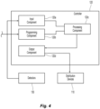
- a preferred centralized controller 120 is shown schematically in FIG. 4 for receiving, processing and generating the various input and output signals from and/or to each of the detectors 130 and fluid distribution devices 110.
- the preferred controller 120 includes a data input component 120a, a programming component 120b, a processing component 120c and an output component 120d.
- the data input component 120a receives detection data or signals from the detectors 130 including, for example, either raw detector data or calibrated data, such as for example, any one of continuous or intermittent temperature data, spectral energy data, smoke data or the raw electrical signals representing such parameters, e.g., voltage or current that would indicate a measured environmental parameter of the occupancy.
- Additional data parameters collected from the detectors 130 can include time data, address or location data of the detector.
- the preferred programming component 120b provides for user-defined operational parameters of the system to sense, measure and analyze a fire including, for example, its location and magnitude of its threat.
- the programming may be hard wired or logically programmed and the signals between system components can be one or more of analog, digital, or fiber optic data. Moreover, communication between components of the system 100 can be any one or more of wired or wireless communication.
- the programming component 120b can provide for input of user-defined algorithms to identify fluid distribution devices or assemblies 110 for operation and their time of operation in response to the fire.
- a known exemplary controller for use in the system 100 is the Simplex ® 4100 Fire Control Panel from TYCO FIRE PROTECTION PRODUCTS of Riverside, MA, which is shown and described in Technical Data Sheet S4100-0031-25 (Nov. 2013 ).
- FIG. 4A Shown in FIG. 4A is one preferred operation or algorithm 160 of the controller 120, in which the processing component 120c processes the input data to detect 162 and locate 164 the fire. Based upon the detection and/or other input data or signals, the processing component 120c identifies 166, in accordance with the programmed algorithm, fluid distribution devices above and about the located fire to address the fire. In one preferred embodiment of the system and the control algorithm, each of the fluid distribution devices 110 are addressable by the controller 120 for controlled actuation. The preferred algorithm 160 can preferably queue the identified devices for actuation at a select or determined threshold moment 168 as defined by the preferred algorithm.
- a minimum number of fluid distribution devices 110 can be identified for controlled actuation 170 to provide the desired fire protection performance, such as for example, control performance, suppression performance, extinguishment or any combination thereof thereby placing a minimized hydraulic demand on the system consistent with the system's preferably minimized hydraulic design as previously described.
- the preferred algorithm 160 provides for the identification of ten or fewer fluid distribution devices 110 above and about the located fire to define the area of device operation, consistent with the hydraulic design of the system, for controlled actuation to address the detected and analyzed fire.
- the algorithm identifies the five, and more preferably the four, closest and adjacent devices above and about the located fire for controlled actuation.
- the processing component 120c identifies one, two or three select distribution devices 110 for controlled actuation in accordance with the algorithm.
- the preferred algorithm provides for the identification of devices above and about the located fire to define the area of device operation for addressing the detected and analyzed fire consistent with the preferred eleven or fewer design fluid distribution devices.
- the algorithm identifies the five, and more preferably the four, closest and adjacent devices above and about the located fire.
- the processing controller 120c identifies one, two or three select distribution devices 110 in accordance with the algorithm.
- the processing component 120c preferably determines a threshold moment 168 in the fire, for example at a preferably incipient stage of the fire, for actuation of the identified and selected fluid distribution devices 110. Accordingly, the preferred processing component 120c and output component 120d of the controller 120 further preferably generate appropriate signals for the output component 120d to control operation 170 of the fluid distribution devices 110 in accordance with the programmed algorithm to effectively address the fire.
- the threshold moment 168 for actuation of the selected fluid distribution devices 110 can be a function of the collected data or parameters from the detectors 130 which measure the fire.
- the threshold moment 168 may define a user-defined threshold heat release, user-defined maximum ceiling temperature, or user-defined rate of temperature rise.
- the detection sub-system 100c preferably continuously monitors the occupancy to identify a fire and its location within the storage occupancy 10. Alternatively, monitoring by the detectors 130 can be intermittent. In preferred embodiments of the system 100, disposed proximate the fluid distribution devices 110 are detectors 130 for monitoring of the storage occupancy 10.
- the detectors 130 can be mounted so that they are axially aligned with the fluid distribution device and more particularly the frame body 110x, as seen for example in FIG. 3A , or may alternatively be above and off-set from the frame body 110x. Shown in FIG. 3B is the embodiment according to the invention, in which two detectors 130a, 130b are disposed above and preferably equally spaced about the frame body 110x for communication with the controller 120.
- the detectors 130 can be disposed elsewhere about the occupancy 10 provided the detectors 130 can monitor the occupancy 10 to detect a fire as described herein. More preferably, the detectors 130 are disposed beneath the ceiling C and above the fluid distribution devices 110 to provide ceiling detection of a fire for preferred continuous monitoring of the occupancy 10. The spaced apart detectors 130 monitor the occupancy to detect changes for any one of temperature, thermal energy, spectral energy, smoke or any other parameter to indicate the presence of a fire in the occupancy.
- the detectors 130 can be any one or combination of thermocouples, thermistors, infrared detectors, smoke detectors and equivalents thereof. More preferably, the detectors 130 provide ceiling detection of a fire product, e.g., temperature or smoke.
- detectors for use in the system include TrueAlarm ® Analog Sensing analog sensors from TYCO SAFETY PRODUCTS WESTMINSTER of Riverside, MA, and shown in Technical Data Sheet S4098-0019-12 (Aug. 2008 ).
- the detectors 130 are coupled to the controller 120 to communicate detection data or signals to the controller 120 of the system 100 for processing as described herein.
- the ability of the detectors 130 to monitor environmental changes indicative of a fire can depend upon the type of detector being used, the sensitivity of the detector, coverage area of the detector, and/or the distance between the detector and the fire origin. Accordingly, the detectors 130 individually and collectively are appropriately mounted, spaced and/or oriented to monitor the occupancy 10 for the conditions of a fire in a manner described.
- the preferably spaced apart detector 130 and fluid distribution device 110 of the system 100 physically separates or uncouples the fire detection and fluid distribution functions between the components.
- the fluid distribution device 110 can be located at any desired distance beneath the ceiling and above the stored commodity.
- the member 110w can be located above the stored commodity 12 and below the ceiling C at a preferred deflector-to-ceiling distance S that is greater than 0.46m (18 inches) and more preferably at a deflector-to-ceiling distance S of at least 0.51m (20 inches). Accordingly, a preferred frame body and its deflector member 110w of the fluid distribution device 110 can be located below the ceiling C without the distance limitations or restrictions provided under the industry accepted installation standards, so long as the deflector of the device 110 is located above the stored commodity to provide the necessary fluid distribution to effectively address a fire.
- the preferred installations of the system 100 can avoid the obstruction requirements under the standards. Therefore, the preferred systems 100 can provide for more flexibility in its installation as compared to known storage fire protection systems using only automatic sprinklers.
- the preferred fluid distribution devices 110, branch lines and main pipe(s) can be arranged so as to define either one of a gridded network or a tree network.
- the network of pipes can further include pipe fittings such as connectors, elbows and risers, etc. to interconnect the network or grid of fluid distribution devices to the fluid distribution portion of the system 100.
- the fluid distribution sub-system 100a further preferably includes a riser pipe 150f which preferably extends from a fluid supply 150e to the main pipes 150a.
- the fluid distribution devices 110 are coupled to a supply of firefighting liquid such as, for example, a water main 150e or water tank.
- the fluid distribution sub-system can further include additional devices (not shown) such as, for example, fire pumps, or backflow preventers to deliver the water to the network of piping at a desired flow rate and/or pressure.
- the riser 150f can include additional components or assemblies to direct, detect, measure, or control fluid flow between the water distribution portion and the network of fluid distribution devices 110.
- the system can include a check valve 152 to prevent fluid flow from the fluid distribution devices back toward the fluid source.
- the system can also include a flow meter 154 for measuring the flow through the riser 150f and the system 100.
- the system 100 is preferably configured as a wet system and can be further configured as a preaction system including variations thereof, i.e., single or double-interlock preaction.
- the riser 150f can include a fluid control valve, such as for example, a solenoid controlled deluge valve which operates upon detection of a fire by the detection sub-system 100c.
- a control actuated system as previously described can be subject to actual fire testing in order to identify or verify preferred hydraulic design parameters including the hydraulic design area and minimum operating pressure for use in a preferred control actuated system installed for protection of a storage occupancy.
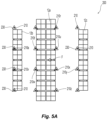
- a plurality of preferred fluid distribution devices 210 and detectors 230 are installed above rack storage of cartoned unexpanded Group A plastic stored to a nominal storage height of 12.19m (40 ft.) under a 13.72m (45 ft.) horizontal ceiling as shown in the plan view of FIG. 5 .
- the fluid distribution devices 210 are installed on 3.05m ⁇ 3.05m (10 ft. ⁇ 10 ft.) spacing and supplied with water so as to provide a flow from each fluid distribution device that is equivalent to a nominal K-factor of 360 litres/min/bar 1 ⁇ 2 (25 GPM/PSI. 1 ⁇ 2 ) supplied with an operating pressure of water at 2.41Bar (35 psi).
- the fluid distribution devices 210 are installed beneath the ceiling so as to locate the deflector of the devices 0.51m (twenty inches (20 in.)) beneath the ceiling C.
- the fluid distribution devices 210 are installed above Group A Plastic commodity that includes single wall corrugated cardboard cartons measuring 0.53m ⁇ 0.53m (21 in. ⁇ 21 in.) containing 125 empty crystalline polystyrene 473ml (16 oz.) cups in separated compartments within the carton.
- Each pallet of commodity is supported by a two-way 1.07m ⁇ 1.07m ⁇ 0.13m (42 in. ⁇ 42 in. ⁇ 5 in.) slatted deck hardwood pallet.
- the commodity is stored in a rack arrangement having a central double-row rack with two single-row target arrays disposed about the central rack. The geometric center of the central rack is centered below four devices as indicated.
- Two half-standard cellulose cotton igniters are constructed from 0.08m ⁇ 0.08m (3 in. ⁇ 3 in.) long cellulosic bundles soaked with 118ml (4 oz.) gasoline and wrapped in a polyethylene bag. The igniters were positioned at the floor and offset 0.53m (21 in.) from the center of the central double row rack main array.
- the igniters are ignited to provide a single fire test F of the system 200.
- the system 200 senses, measures and responds to the fire with a preferred control algorithm, for example, such as an algorithm previously described.
- a preferred control algorithm for example, such as an algorithm previously described.
- a total of nine fluid distribution devices 210r, 210s, 210t, 210u, 210v, 210w, 210x, 210y, 210z are identified for operation and operated within two minutes of ignition.
- the nine fluid distribution devices included four devices 210t, 210u, 210w, 210x located above and about the test fire F to define an included area of device operation of about 37.16m 2 (400 square feet).
- the four operated fluid distribution devices 210t, 210u, 210w, 210x effectively addressed the fire such that the fire and damage to the commodity was contained within the area of device operation and therefore did not spread to the ends of the main array or across the aisles to the targets.
- the maximum one-minute gas temperature above ignition was measured to be 154°C (309°F) and the maximum one-minute average steel temperature above ignition was measured to be 61°C (142°F).
- the inventors believe that the preferred systems and methods described herein can be used to provide fire protection systems for storage with hydraulic demands lower than previously known.
- the fire test showed that a device operational area of less than 71.35m 2 (768 square feet) and more particularly an operational area of 37.16m 2 (400 square feet) or less was effective in addressing a fire of a high hazard commodity. It is believed that the test setup could be alternatively configured with a smaller device spacing, water delivery pressure and appropriate algorithm to operate, for example, only the four fluid distribution devices above and about the test fire F to identify an operational area of 23.78m 2 (256 square feet) or other area to effectively address the high challenge test fire.
- preferred embodiments of the system 100 can be preferably hydraulically designed with a hydraulic design area having or equal to minimal operational area of less than 71.35m 2 (768 square feet), more preferably 37.16m 2 (400 square feet) or less and even more preferably 23.78m 2 (256 square feet) and with a minimum design pressure equal to the test pressure to protect a hazard equal to or less than the test hazard.
- additional hydraulic design parameters identified from the test results can include a hydraulic demand defined by a preferred minimum number of design fluid distribution devices and a minimum operating pressure for use in a preferred controlled actuated system for protection of a storage occupancy.
- the maximum number of design fluid distribution devices can be derived from directly or indirectly from the number of fluid distribution devices identified and actuated in the large-scale fire test to satisfactorily address the fire.
- a hydraulic demand defined by a preferred number of design fluid distribution devices being less than twelve, preferably nine or fewer and more preferably ranging from eight to six and more preferably ranging from six to four design fluid distribution devices.
- the number of design fluid distribution devices is less than any one of: (i) twelve sprinklers, the design devices providing standard coverage; (ii) eight sprinklers, the design devices providing extended coverage on 3.66m ⁇ 3.66m (12 ft. ⁇ 12 ft.) device-to-device spacing; or (iii) six sprinklers, the design devices providing extended coverage on 4.27m ⁇ 14.27m (14 ft. ⁇ 14 ft.) device-to-device spacing.
- a preferred minimum operating pressure identified for use can be at least 2.41Bar (35 psi.) or any minimum operating pressure for use with the preferred fluid distribution device to effectively address a fire in a preferred manner as described herein.
- one or more preferred hydraulic design parameters defining the hydraulic demand of the system include a preferred number of design fluid distribution devices, a minimum operation pressure and/or a preferred minimized hydraulic design area smaller than previously known can be provided for use in a preferred controlled actuated system for protection of a storage occupancy.
- the piping and other fluid distribution equipment can be appropriately sized in accordance with the hydraulic demand and design of the system.
- the preferred system 100 is further preferably defined by the storage occupancy in which it is installed.
- Parameters defining the system installation preferably include ceiling height H1 of the storage occupancy 10, storage height H2 of the commodity 12, classification of the commodity 12 and the storage arrangement of the commodity 12 to be protected.
- the ceiling C of the occupancy 10 can be of any configuration including any one of: a flat ceiling, horizontal ceiling, sloped ceiling or combinations thereof.
- the ceiling height H1 is preferably defined by the distance between the floor of the storage occupancy 10 and the underside of the ceiling C above (or roof deck) within the storage area to be protected, and more preferably defines the maximum height between the floor and the underside of the ceiling C above (or roof deck).
- the ceiling height H1 can be 6.1m (twenty feet (20 ft.)) or greater, and can be nominally 9.14m (thirty feet (30 ft.)) or greater, for example, up to a nominal 13.72 (forty-five feet (45 ft.)) or higher such as for example up to 18.29m (sixty feet (60 ft.)) or even greater.
- the stored commodity 12 can be configured as a commodity array 12, preferably of a type which can include any one of NFPA-13 defined Class I, II, III or IV commodities, alternatively Group A, Group B, or Group C plastics, elastomers, and rubbers, including exposed and unexposed expanded plastics or further in the alternative any type of commodity capable of having its combustion behavior characterized.
- the commodity array 12 can be characterized by one or more of the parameters provided and defined in Section 3.9.1 of NFPA-13.
- the array 12 can be stored to a storage height H2, in which the storage height H2 preferably defines the maximum height of the storage and a nominal ceiling-to-storage clearance CL between the ceiling and the top of the highest stored commodity.
- the storage height H2 can be 3.67m (twelve feet (12 ft.)) or greater and can be nominally 6.1m (twenty feet (20 ft.)) or greater, such as for example, up to a nominal 18.29m (sixty feet) or greater, preferably ranging nominally from between 6.1m and 18.29m (twenty feet and sixty feet), including being for example a nominal 16.76 (fifty-five (55 ft.).
- the storage height H2 can be maximized beneath the ceiling C to preferably define a minimum nominal ceiling-to-storage clearance CL of any one of 0.3m (one foot), 0.61m (two feet), 0.91m (three feet), 1.22m (four feet), or 1.52m (five feet (5 ft.)) or anywhere in between.
- the stored commodity array 12 can preferably define a rack arrangement, preferably a multi-row rack storage arrangement; and even more preferably a double-row rack storage arrangement.
- the commodity array can includes spaced apart rack arrangements, 12a, 12b, 12c with an aisle spacing therebetween W1, W2.
- the stored commodity array 12 preferably defines a high-piled storage commodity (in excess of 3.67m (twelve feet (12 ft.))) rack arrangement, such as for example, a single-row rack arrangement, preferably a multi-row rack storage arrangement; and even more preferably a double-row rack storage arrangement.
- a high-piled storage commodity in excess of 3.67m (twelve feet (12 ft.)) rack arrangement, such as for example, a single-row rack arrangement, preferably a multi-row rack storage arrangement; and even more preferably a double-row rack storage arrangement.
- non-rack storage arrangements including for example: palletized, solid-piled (stacked commodities), bin box (storage in five sided boxes with little to no space between boxes), shelf (storage on structures up to and including 0.76m (thirty inches) deep and separated by aisles of at least 0.76m (thirty inches) wide) or back-to-back shelf storage (two shelves separated by a vertical barrier with no longitudinal flue space and maximum storage height of 4.57m (fifteen feet)).
- Other storage configurations are possible, as defined by NFPA 13 such as for example, on floor, rack without solid shelves.
- the storage area can also include additional storage of the same or different commodity spaced at an aisle width W in the same or different configuration.
Landscapes
- Health & Medical Sciences (AREA)
- Public Health (AREA)
- Business, Economics & Management (AREA)
- Emergency Management (AREA)
- Engineering & Computer Science (AREA)
- Operations Research (AREA)
- Fire-Extinguishing By Fire Departments, And Fire-Extinguishing Equipment And Control Thereof (AREA)
Description
- The present invention relates generally to fire protection systems for storage. More specifically, the present invention involves fire protection systems for storage arrangements having a reduced hydraulic demand for comparable sized storage arrangements.
- Industry accepted system installation standards and definitions for storage fire protection are provided in National Fire Protection Association publication, NFPA 13: Standard for the Installation of Sprinkler Systems (2013 ed.) ("NFPA 13"). Chapters 11-12 define standardized hydraulic design approaches for systems designed and installed with "automatic" storage sprinklers, such as for example, standard spray, control mode specific application (CMSA), extended coverage or early suppression fast response (ESFR). NFPA 13 defines "automatic sprinklers" as "a fire suppression or control device that operates automatically when its heat-activated element is heated to its thermal rating or above, allowing water to discharge over a specified area." As used herein, a "hydraulically designed system," is a calculated system in which pipe sizes are selected on a pressure loss basis to provide a prescribed water density, in gallons per minute per square foot, or a prescribed minimum discharge pressure or flow per sprinkler, distributed with a reasonable degree of uniformity over a specified area. The standards specify the hydraulic design area or sprinkler operational area, the density (GPM/SQ. FT) requirements, and/or minimum operating pressures for a given storage commodity and arrangement. A "hydraulic design area" is an area, defined in square units of measure, comprising a defined number of hydraulically remote sprinklers at a defined spacing between each sprinkler. "Hydraulically remote sprinklers" are sprinklers that place the greatest water demand on a system in order to provide a prescribed minimum discharge pressure or flow. It is understood by those skilled in the art that the hydraulically remote sprinklers may or may not be physically located the furthest from the fluid the water supply providing the prescribed minimum pressure or flow.
- Chapter 21 of NFPA 13 provides for special approaches that permit hydraulic designs other than those specified under Chapters 11-20. According to Section 21.1.8, the hydraulic design area can be defined by a number of design sprinklers as derived from worst-case results obtained from full-scale fire testing. However, regardless of the fire test results, the special design approaches of NFPA still include minimum design requirements. For example, Section 21.1.8.1 requires that the number of design sprinklers defining the hydraulic demand be no less than: (i) twelve sprinklers for standard coverage sprinklers; (ii) eight sprinklers for extended coverage sprinklers on 3.66m × 3.66m (12 ft. × 12 ft.) sprinkler-to-sprinkle spacing; or
(iii) six sprinklers for extended coverage sprinklers based on 4.27m × 4.27m (14 ft. × 14 ft.) sprinkler-to-sprinkler spacing. Moreover, Section 21.1.8.2 provides that the minimum operating area based on the sprinkler-to-sprinkler spacing of the given number of design sprinklers shall be no less than 71.3m2 (768 square feet). Other industry accepted standards, for example standards under FM Global (FM), define the number of design sprinklers for use in sprinkler systems for a storage occupancy based upon sprinkler orifice size, orientation, RTI (thermal response), spacing, and minimum operating pressure. Additionally, the number of sprinklers is determined by a fire test in which an appropriate safety factor is assessed on the total number of sprinklers that operate, such as for example, a 50% safety factor. The safety factor is designed to account for uncertainty in the operation sequence inherent to thermo-mechanically operated automatic sprinkler systems due to things such as sprinkler skipping, fire chasing, etc. The hydraulic designs and demand of the system define the water supply requirements of the system and the economic burden to fulfill those requirements, such as for example, by supplying the appropriate number and size of pump, piping or other fluid distribution equipment to meet the hydraulic designs. Accordingly, there is a desired balance between fulfilling a level of hydraulic demand and the economic burden to supply that demand in order to provide a desired level of fire protection. Generally, it is advantageous to minimize the hydraulic design area and/or number of design sprinklers of a system in order to reduce the overall hydraulic demand of the system in order to strike the appropriate balance. - In addition to specifying hydraulic design requirements, the installation standards also include location requirements for the automatic sprinklers. Automatic sprinklers are located above the stored commodity at or near the ceiling of the occupancy in order that its heat-activated element can be activated by the air/gases heated by a fire in the occupancy. Section 8.12.4 of NFPA 13 also includes "distance below ceiling" requirements to locate the deflector of the automatic sprinkler below the ceiling of the storage occupancy. According to the standards, a deflector of a pendent sprinkler is to be located at a maximum of 45.72cm (18 inches) from the ceiling. The construction of the storage occupancy, particularly at or near the ceiling, can present obstructions to the spray pattern of a sprinkler, obstructions can include for example, beams, ducts, lights, trusses or bar joists at or near the ceiling. Accordingly, the installation standards provide for obstruction standards. Section 8.12.5 of NFPA 13 includes obstruction rules or requirements for Early Suppression Fast-Response Sprinklers to ensure that the sprinkler and its spray are clear of obstructions at or near the ceiling. The obstruction standards provide for a maximum allowable distance of the deflector above the bottom of the obstruction based upon the distance of the sprinkler from the side of the obstruction. Accordingly, both the structure of the automatic sprinkler and the existing installation standards can limit or restrict the ability to install a sprinkler above a stored commodity at increased distances from the ceiling which can add a burden to installing a system to provide a desired level of fire protection.
- Thus, known fire protection systems that employ automatic sprinklers to protect storage occupancies have hydraulic and installation limitations that can add to the overall economic burden to provide the desired level of fire protection. It is therefore desirable to have systems and methods that can reduce the hydraulic demand of a system and/or provide an installation flexibility to provide fire protection for storage occupancies.
- According to the invention, there is provided a fire protection system for protection of a storage occupancy having a ceiling defining a nominal ceiling height, the system comprising:
- a plurality of fluid distribution devices disposed beneath the ceiling and above a high-piled storage commodity in the storage occupancy having a nominal storage height greater than 3.66m (twelve feet (12 ft.)), each of the plurality of fluid distribution devices being arranged for selective identification and controlled actuation in response to a fire; and
- a hydraulic demand of the system defined by at least one of:
- i) a hydraulic design area having a minimum operational area of less than 71.35m2 (768 square feet); or
- ii) a number of design fluid distribution devices, the number of design fluid distribution devices being less than twelve, the number of design fluid distribution devices having a device-to-device spacing is at any one of 2.4m × 2.4m (8ft. × 8ft); 3m × 3m (10 ft. × 10ft); 3.66m × 3.66m (12 ft. × 12 ft); or 4.27m × 4.27m (14 ft. × 14 ft),
- further comprising:
- a fluid distribution system including a network of pipes interconnecting the fluid distribution devices to a supply of firefighting fluid;
- a plurality of detectors to monitor the occupancy for the fire; and
- a controller coupled to the plurality of detectors to detect and locate the fire,
- the controller being coupled to each of the fluid distribution devices to identify and control operation of a select number of fluid distribution devices above and about the fire,
- wherein the controller includes an input component coupled to each of the plurality of detectors for receipt of an input signal from each of the detectors, a processing component for determining a threshold moment in growth of the fire; and an output component to generate an output signal for operation of each of the identified fluid distribution devices in response to the threshold moment, the fluid distribution device includes a deflector member having a deflector position at a deflector-to-ceiling distance greater than 45.72cm (eighteen inches (18 in.)), wherein the network of pipes comprises one or more main pipes, and one or more branch pipes extending from the one or more main pipes, wherein the fluid distribution devices are mounted to and spaced along the branch pipes,
- wherein the plurality of detectors are locating proximate or near the ceiling, the deflector members are located below the ceiling and above the high-piled storage commodity; wherein the plurality of detectors includes two detectors for each fluid distribution device, and wherein the fluid distribution devices are selectively identified for controlled actuation at an incipient stage of the fire.
- According to the invention, there is provided a method of fire protection of a storage occupancy having a nominal ceiling height of thirty feet or greater, the method comprising:
- spacing a plurality of fluid distribution devices at the ceiling for select operation in response to a fire; and
- interconnecting the plurality of fluid distribution devices to a supply of firefighting fluid with a network of pipes, the network of pipes and plurality of fluid distribution devices having a hydraulic demand defined by at least one of:
- i) a hydraulic design area having a minimum operational area of less than 768 square feet; or
- ii) a number of design devices being less than twelve, spacing is at any one 2.4m × 2.4m (8ft × 8ft); 3m × 3m (10 ft. × 10ft); 3.66m × 3.66m (12 ft. × 12 ft); or 4.27m × 4.27m (14 ft. × 14 ft);
- wherein the system further comprises a fluid distribution system including a network of pipes interconnecting the fluid distribution devices to a supply of firefighting fluid; a plurality of detectors to monitor the occupancy for the fire; and
- a controller coupled to the plurality of detectors to detect and locate the fire, the controller being coupled to each of the fluid distribution devices to identify and control operation of a select number of fluid distribution devices above and about the fire;
- wherein the network of pipes comprises one or more main pipes, and one or more branch pipes extending from the one or more main pipes, wherein the fluid distribution devices are mounted to and spaced along the branch pipes;
- wherein the controller includes an input component coupled to each of the plurality of detectors for receipt of an input signal from each of the detectors, a processing component for determining a threshold moment in growth of the fire; and an output component to generate an output signal for operation of each of the identified fluid distribution devices in response to the threshold moment,
- wherein the plurality of detectors includes two detectors for each fluid distribution device, and the method further comprising selectively operating the fluid distribution devices at an incipient stage of the fire.
- Although the Disclosure of the Invention and the preferred systems and methods described herein address the limitations of fire protection systems using automatic fire protections sprinklers under known design criteria, it be to be understood that the preferred systems and method can provide for storage fire protection using controlled actuated fluid distribution devices in systems of any desired hydraulic demand. The Disclosure of the Invention is provided as a general introduction to some embodiments of the invention, and is not intended to be limiting to any particular configuration or system. It is to be understood that various features described in the claims can be combined in any suitable way to form any number of embodiments of the invention. Some additional example embodiments including variations and alternative configurations are provided herein.
- The accompanying drawings, which are incorporated herein and constitute part of this specification, illustrate exemplary embodiments of the invention and, together with the general description given above and the detailed description given below, serve to explain the features of the invention. It should be understood that the preferred embodiments are some examples of the invention as provided by the appended claims.
-
FIG. 1 is a representative illustration of one preferred embodiment of a fire protection system for storage. -
FIG. 1A is a schematic illustration of the embodiment ofFIG. 1 . -
FIGS. 2A &2B are schematic illustrations of operation of the system ofFIG. 1 . -
FIG. 2C is a graphic showing the preferred response time of the system ofFIG. 1 . -
FIGS. 3A-3B are schematic illustrations of fluid distribution and detector arrangements for use in the system ofFIG. 1 . -
FIG. 4 is a schematic illustration of a controller arrangement for use in the system ofFIG. 1 . -
FIG. 4A is a preferred embodiment of controller operation of the system ofFIG. 1 . -
FIG. 5A is a schematic illustration of a test system using a preferred embodiment of the system ofFIG. 1 . - Shown in
FIG. 1 is a preferred embodiment of afire protection system 100 for the protection of astorage occupancy 10 and one or more storedcommodities 12. The preferred systems and methods provide fire protection of a storage occupancy by: (i) sensing a fire; (ii) measuring the fire including its location and size; (iii) analyzing the fire; (iv) responding to the fire with controlled actuation of one or more selectively identified fire protection devices; and (v) terminating the threat from the fire by effectively addressing the fire. The preferred systems can effectively address the fire with any one of fire control, fire suppression, extinguishment or a combination thereof. The industry accepted definition of "fire suppression" for storage protection is sharply reducing the heat release rate of a fire and preventing its regrowth by means of direct and sufficient application of a flow of water through the fire plume to the burning fuel surface. The industry accepted definition of "fire control" is defined as limiting the size of a fire by distribution of a flow of water so as to decrease the heat release rate and pre-wet adjacent combustibles, while controlling ceiling gas temperatures to avoid structural damage. - As schematically shown in
FIGS. 2A and2B , the preferred systems described herein include afluid distribution sub-system 100a, acontrol sub-system 100b and adetection sub-system 100c. The detection and control sub-systems work together, preferably by communication of one or more detection signals DS, to sense, measure and analyze a fire. The control andfluid distribution sub-systems - The time at which the volumetric flow V of firefighting fluid is released is preferably determined so as to minimize the overall hydraulic demand on the system yet be sufficient to effectively address the size of the fire at the time of delivery. Shown in
FIG. 2C is a comparative graph 400 of heat release versus water application to show the preferred time of controlled actuation of thepreferred system 100 as compared to known systems using independently actuated thermally responsive automatic sprinklers, such as for example, systems using early suppression fast response (ESFR) automatic sprinklers. The graph 400 shows afirst curve 402 showing the actual delivery density (ADD) of water (in flow per area of application, e.g., gallons per minute per square foot (GPM/SQ. FT.) ) delivered to a stored commodity, at the commodity, as the heat release rate of fire increases. Asecond curve 404 shows the required delivery density (RDD) of water required to be delivered to the stored commodity at the commodity in order to provide fire suppression by water delivered at a minimum density. The intersection of the ADD and RDD curves defines a time ormoment 406 of heat release in the fire in which ADD and RDD are equal to one another. It is believed that any moment in the fire heat release or growth before (or to the left) of theintersection 406 of ADD and RDD can provide for fire suppression performance because the ADD is greater than the RDD. For example,line 408 graphically shows a moment of early suppression with an early suppression fast response (ESFR) fire protection sprinkler using only automatic thermal response. Because thepreferred system 100 can provide for a controlled actuation, thepreferred system 100 can provide for system response to a fire that is earlier than known ESFR systems. More specifically, the preferred control anddetection sub-systems fluid distribution sub-systems Line 410 shows a preferred time in the fire growth or heat release that is earlier than know ESFR system responses (line 408) at which thepreferred system 100 is operated to address and more preferably suppress the fire. It is believed that the water demand of thesystem 100 is reduced as compared to known systems because the moment of controlled response defines an RDD that is smaller than the RDD of known suppression systems responding with only an automatic thermal response. It should be understood that the controlled system response of thesystem 100 can be controlled to alternatively provide for either standard response or early response to effectively address the fire. - Referring again to
FIG. 1 , thepreferred system 100 includes a plurality offluid distribution devices 110, a plurality ofdetectors 130 and acentralized controller 120 for communication with each of thefluid distribution devices 110 anddetectors 130. A preferred embodiment of thefluid distribution device 110 includes afluid deflecting member 110w coupled to aframe body 110x as schematically shown inFIGS. 3A and 3B and arranged for controlled actuation in manner described herein. Theframe body 110x includes an inlet for connection to the piping network and an outlet with an internal passageway extending between the inlet and the outlet. The deflectingmember 110w is preferably axially spaced from the outlet in a fixed spaced relation. Water or other firefighting fluid delivered to the inlet is discharged from the outlet to impact the deflectingmember 110w and generate a volumetric flow of fluid to effectively address a fire in a manner as described herein. Alternatively, the deflecting member can translate with respect to the outlet provided it distributes the firefighting fluid in a desired manner upon operation. Further in the alternative, the deflector or deflecting member can be oriented horizontal with respect to the commodity or otherwise oriented, for example, in an upright orientation relative to the frame body and its outlet. Accordingly, thefluid distribution device 110 can be structurally embodied with a frame body and deflector member of an "automatic fire protection sprinkler" as understood in the art and appropriately configured or modified for controlled actuation as described herein. This configuration can include the frame body and deflector of known automatic fire protection sprinklers with modifications described herein. The frame body and deflectors components for use in the preferred systems and methods can include the components of known automatic sprinklers that have been tested and found by industry accepted organizations to be acceptable for a specified sprinkler performance, such as for example, standard spray, suppression, or extended coverage and equivalents thereof. Alternate embodiments of thefluid distribution devices 110 for use in thesystem 100 include nozzles, misting devices or any other devices configured for controlled operation to distribute a volumetric flow of firefighting fluid in a manner described herein. - The
fluid distribution devices 110 of thepreferred system 100 are interconnected by thefluid distribution sub-system 100a. The fluid distribution sub-system includes a network ofpipes 150 preferably having one or moremain pipes 150a from which one ormore branch lines fluid distribution devices 110 are mounted or connected to thebranch lines FIG. 1A , thefluid distribution devices 110 are installed beneath a ceiling C of a storage occupancy, such as for example, a warehouse above astorage commodity 12. As shown inFIG. 1A andFIGS. 3A ,-3B, where thepreferred device 110 includes a deflector member ordeflector 110w, thedeflector 110w can be located below the ceiling C and above the storedcommodity 12 to define a preferred deflector position at a preferred desired-to-ceiling distance S. The distribution 'devices 110 are preferably mounted to and spaced along the spaced-apartbranch pipes FIG. 1 . The device-to-device spacing is preferably 2.43m × 2.43m (8 ft. × 8 ft.); 3.05m × 3.05m (10 ft. × 10 ft.); 3.66m × 3.66m (12 ft. × 12 ft.); 4.27m × 4.27m (14 ft. × 14 ft.) or any combination thereof. - The hydraulic demand can be directly related to the area of device operation over which a number of identified devices are controlled and operated to effectively address the fire in a manner as described herein. Accordingly, in a preferred aspect of the
system 100, the spacing of thefluid distribution devices 110 defines the hydraulic demand of the system. The operation of thefluid distribution devices 110 in thepreferred system 100 is not directly or independently triggered or actuated by a thermal or heat-activated response to a fire as in known "automatic sprinklers". Instead, the actuation of thefluid distribution devices 110 is controlled by thepreferred controller 120 of thepreferred control sub-system 100b. More specifically, thefluid distribution devices 110 are coupled directly or indirectly with thecontroller 120 to operate a select number of identified devices for distribution of a preferably fixed volumetric flow of fluid to effectively address the fire. Because thepreferred system 100 can consistently control the number ofdevices 110 actuated to address a fire, the hydraulic demand can be controlled and therefore preferably minimized in a manner described herein. More particularly, thepreferred system 100 provides for a controlled response to a fire by selecting the number and location of thedevices 110 to define an area of operation above and disposed about the fire, in addition to controlling the time of actuation of the selected sprinklers to effectively address the fire. By preferably minimizing the operational area of the fluid distribution devices alone or in combination with a threshold moment for device actuation in the incipient stages of fire growth, the hydraulic demand of thesystem 100 is preferably minimized. It is believed that the preferred controlled operation of thesystem 100 can provide for a hydraulic demand that is smaller than known system designs using automatic fire protection sprinklers of comparable flow and distribution characteristics configured to protect the same occupancy. - The preferred storage
fire protection system 100 and its demand is preferably hydraulically designed with a hydraulic design area A or area of device operation being less than about about 71.35m2 (768 square feet), preferably less than 69.68m2 (750 square feet); more preferably less than 65.03m2 (700 square feet); and even more preferably equal to or less than about 53.51m2 (576 square feet). As used herein and schematically illustrated inFIG. 1 , a "hydraulic design area A" is an area, defined in square units of measure, comprising a defined number of hydraulically remote fluid distribution devices at a defined spacing between each device. "Hydraulically remote devices" are fluid distribution device that places the greatest water demand on thesystem 100 in order to provide a prescribed minimum discharge pressure or flow. Alternatively or additionally, the preferred storagefire protection system 100 and its demand is preferably hydraulically designed based upon a preferred number of hydraulically remote devices, e.g., the "design fluid distribution devices" being provided with a preferred minimum operating pressure. - In one preferred embodiment of the
system 100 in which a fire can be effectively addressed by four adjacentfluid distribution devices 110 above and about the fire, the hydraulic design area A is preferably defined by four hydraulically remote devices and the spacing therebetween. The preferred four hydraulically remote devices include two devices per branch lines on two branch lines with a device-to-device spacing of 3.05m (eight feet (8 ft.)) along and between the two branch lines to define a hydraulic design area that is preferably 23.78m2 (256 square feet). The device-to-device spacing can be varied to be any one of 3.05m (ten feet (10 ft.)) or 3.66m (twelve feet (12 ft.)) to respectively define hydraulic design areas A being any one of 37.16m2 (400 square feet) or 53.51m2 (576 square feet). Alternatively, the hydraulic design area A is defined by nine (9) hydraulically remote fluid distribution devices with three devices per branch line on three branch lines with a device-to-device spacing of 2.43m (eight feet (8 ft.)) along and between the three branch lines to define a hydraulic design area A of 53.51m2 (576 square feet). Accordingly, thepreferred system 100 can be hydraulically designed with a hydraulic design area that is smaller than currently available under the known installation standards. Additionally or alternatively, the hydraulic demand of thesystem 100 is preferably defined by a number of design fluid distribution device being less than twelve and having at least four, preferably having eleven or fewer and more preferably ranging from eight to six and more preferably ranging from six to four. - As hydraulic remote fluid distribution devices, the
devices 110 defining the preferably minimized hydraulic design area A or preferred minimum design devices provide a prescribed volumetric flow at a minimum fluid pressure sufficient to address a fire of a particular size or a fire of a particular hazard. Thefluid distribution devices 110 in thesystem 100 are provided with a preferred minimum operating pressure range that can effectively address a worst-case scenario test fire with any one of fire control, fire suppression or a combination thereof when the operating pressure is provided to the fluid distribution devices defining a test operational area that is configured as one of the preferred hydraulic design areas A as previously described. Accordingly, a preferred controlled actuated system and its fluid distribution devices can be installed in a test-fire setup for a controlled actuation to define a desired test operational area that effectively addresses a test fire of a particular test commodity or hazard with a given test pressure. Based on satisfactory test performance, thesystem 100 can be preferably hydraulically designed with a minimum hydraulic design area equal to the test operational area and with a minimum design pressure equal to the test pressure to protect a hazard equal to or less than the test hazard. An exemplary test-fire setup is described below. - From the test results, hydraulic design parameters including the preferred minimum number of design fluid distribution devices and a minimum operation pressure can be provided for use in the preferred controlled actuated
system 100 for protection of a storage occupancy. By preferably minimizing the number ofdevices 110 operated to address a fire, alone or in combination with a time of their operation at an incipient stage in the fire growth, the hydraulic demand of thesystem 100 is preferably minimized. It is believed that the preferred controlled operation of thesystem 100 can provide for a hydraulic demand that is smaller than known system designs using automatic fire protection sprinklers configured to protect the same occupancy. In a preferred embodiment, the hydraulic demand of thesystem 100 is preferably defined by a number of design fluid distribution devices being less than twelve, eleven or fewer and more preferably ranging from eight to six and more preferably ranging from six to four. -
Fluid distribution device 110 in the preferred systems and methods can include frame bodies and or deflector members of standard spray sprinklers, suppression sprinklers or extended coverage sprinklers and equivalents thereof which are suitable for use in storage applications. For example,U.S. Patent No. 8,176,988 shows an exemplary fire protection sprinkler frame and deflector for use in the systems described herein. Specifically shown and described inU.S. Patent No. 8,176,988 is an early suppression fast response sprinkler (ESFR), its sprinkler frame body and embodiments of deflecting member or deflector. The sprinkler shown inU.S. Patent No. 8,176,988 is a pendent-type sprinkler; however upright-type sprinklers can be configured for use in the systems described herein. More preferably, sprinklers for configuration and use in the described systems herein include ESFR pendent sprinklers having a nominal K-factor of 362.88 litres/min/bar½ (25.2 GPM/(PSI)½). A preferredfluid distribution device 110 for installation in thesystem 100 includes the frame body and deflector of the Model ESFR-25 Early Suppression, Fast Response Pendent Sprinkler from TYCO FIRE PRODUCTS, LP of Lansdale, PA having a nominal 25.2 K-factor ESFR. The preferred frame body and deflector member is shown in Tyco Fire Products, LP technical data sheet, TFP312 entitled, "Model ESFR-25, Early Suppression Fast Response Pendent Sprinklers 25.2 K-factor" (Nov. 2012). As used herein, the K-factor is defined as a constant representing the discharge coefficient that is quantified by the flow of fluid in gallons per minute (GPM) from the outlet of the frame body divided by the square root of the pressure of the flow of fluid fed into the inlet of the frame passageway in pounds per square inch (PSI). The K-factor is expressed as litres/min/bar½ (GPM/(PSI)½). A rated or nominal K- factor or rated discharge coefficient of a sprinkler as a mean value over a K-factor range. For example, for a K-factor 11 or greater, NFPA 13 provides the following nominal K-factors (with the K-factor range shown in parenthesis): (i) 161.28 (154.08-168.84) litres/min/Bar1/2 (11.2 (10.7-11.7) GPM/(PSI)½); (ii) 201.6 (194.4-208.8) litres/min/Bar1/2 (14.0 (13.5-14.5) GPM/(PSI)1/2); (iii) 483.84 (457.92-501.12) litres/min/Bar1/2 (16.8 (16.0-17.6) GPM/(PSI)1/2); (iv) 282.24 (267.84-296.64) litres/min/Bar1/2 (19.6 (18.6-20.6) GPM/(PSI)1/2); (v) 322.56 (306.72-338.40) litres/min/Bar1/2 (22.4 (21.3-23.5) GPM/(PSI)1/2); (vi) 362.88 (344.16-381.60) litres/min/Bar1/2 (25.2 (23.9-26.5) GPM/(PSI)1/2); (vii) 403.2 (383.04-423.36) litres/min/Bar1/2 (28.0 (26.6-29.4) GPM/(PSI)½); and (viii) 483.84 (457.92-501.12) litres/min/Bar1/2 (33.6 (31.8-34.8) GPM/(PSI)½). Alternate embodiments of thefluid distribution device 110 can include sprinklers having the aforementioned nominal K-factors or greater. - Shown in
FIGS. 3A and 3B are schematic representations of preferred electro-mechanical coupling arrangements between a distribution device assembly ordevice 110 and thecontroller 120 for controlled actuation of the device. Shown inFIG. 3A is a fluiddistribution device assembly 110 that includes asprinkler frame body 110x having an internal sealing assembly supported in place by a removable structure, such as for example, a thermally responsive glass bulb trigger. A transducer and preferably electrically operatedactuator 110y is arranged, coupled, or assembled, internally or externally, with theframe body 110x for displacing the support structure by fracturing, rupturing, ejecting, and/or otherwise removing the support structure and its support of the sealing assembly to permit fluid discharge from the frame body. Theactuator 110y is preferably electrically coupled to thecontroller 120 in which the controller provides, directly or indirectly, an electrical pulse or signal for signaled operation of the actuator to displace the support structure and the sealing assembly for controlled discharge of firefighting fluid from theframe body 110x to impact adeflector member 110w. - Alternate or equivalent distribution device electro-mechanical arrangements for use in the system are shown in
U.S. Patent Nos. 3,811,511 ;3,834,463 or4,217,959 . Shown and described inFig. 2 ofU.S. Patent No. 3,811,511 is a sprinkler and electrically responsive explosive actuator arrangement in which a detonator is electrically operated to displace a slidable plunger to rupture a bulb supporting a valve closure in the sprinkler head. Shown and described inFig. 1 ofU.S. Patent No. 3,834,463 is a sensitive sprinkler having an outlet orifice with a rupture disc valve upstream of the orifice. An electrically responsive explosive squib is provided with electrically conductive wires that can be coupled to thecontroller 120. Upon receipt of an appropriate signal, the squib explodes to generate an expanding gas to the rupture disc to open the sprinkler. Shown and described inFIG. 2 ofU.S. Patent No. 4,217,959 is an electrically controlled fluid dispenser for a fire extinguishing system in which the dispenser includes a valve disc supported by a frangible safety device to close the outlet orifice of the dispenser. A striking mechanism having an electrical lead is supported against the frangible safety device. The patent describes that an electrical pulse can be sent through the lead to release the striking mechanism and fracture the safety device thereby removing support for the valve disc to permit extinguishment fluid to flow from the dispenser. - Shown in
FIG. 3B . is another preferred electro-mechanical arrangement for controlled actuation that includes an electrically operatedsolenoid valve 110z in line and upstream from an opensprinkler frame body 110x to control the discharge from the device frame. With no seal assembly in the frame outlet, water is permitted to flow from theopen frame body 110x upon thesolenoid valve 110z receiving an appropriately configured electrical signal from thecontroller 120 to open the solenoid valve depending upon whether the solenoid valve is normally closed or normally open. Water again discharged from the frame outlet to impact adeflector member 110w. Exemplary known electrically operated solenoid valves for use in thesystem 100 can include the electric 2/2 Series 8210 Pilot Operated General Service Solenoid Valves from ASCO® and equivalents thereof. - Referring to
FIGS. 2A and2B and thepreferred system 100 for fire protection of storage, thedetection sub-system 100c and itspreferred detectors 130 sense and analyze, directly or indirectly, a fire in theoccupancy 10. The detection sub-system monitors 100c the occupancy to determine environmental changes to identify a fire and its location within thestorage occupancy 10. Thesystem 100 and thecontroller sub-system 100b preferably include one ormore controllers 120 and more preferably acentralized controller 120 coupled to thedetectors 130 andfluid distribution devices 110 for the controlled actuation of a defined or select group ofdevices 110 for distribution of the preferred volumetric flow of firefighting fluid to address the detected fire. Based upon the input from thedetectors 130, thecentralized controller 120 identifies ten orfewer devices 110 above and about the located fire to define the area of device operation, consistent with the hydraulic design area A of the system as previously described. In one preferred embodiment, thecontroller 120 identifies the ten or fewer, and more preferably the four or fewer, fluid distribution devices above and about the located fire for controlled actuation. Alternatively, thecontroller 120 identifies one, two or threeselect distribution devices 110 for addressing the detected fire. - A preferred
centralized controller 120 is shown schematically inFIG. 4 for receiving, processing and generating the various input and output signals from and/or to each of thedetectors 130 andfluid distribution devices 110. Functionally, thepreferred controller 120 includes adata input component 120a, aprogramming component 120b, aprocessing component 120c and anoutput component 120d. Thedata input component 120a receives detection data or signals from thedetectors 130 including, for example, either raw detector data or calibrated data, such as for example, any one of continuous or intermittent temperature data, spectral energy data, smoke data or the raw electrical signals representing such parameters, e.g., voltage or current that would indicate a measured environmental parameter of the occupancy. Additional data parameters collected from thedetectors 130 can include time data, address or location data of the detector. Thepreferred programming component 120b provides for user-defined operational parameters of the system to sense, measure and analyze a fire including, for example, its location and magnitude of its threat. The programming may be hard wired or logically programmed and the signals between system components can be one or more of analog, digital, or fiber optic data. Moreover, communication between components of thesystem 100 can be any one or more of wired or wireless communication. Theprogramming component 120b can provide for input of user-defined algorithms to identify fluid distribution devices orassemblies 110 for operation and their time of operation in response to the fire. A known exemplary controller for use in thesystem 100 is the Simplex® 4100 Fire Control Panel from TYCO FIRE PROTECTION PRODUCTS of Westminster, MA, which is shown and described in Technical Data Sheet S4100-0031-25 (Nov. 2013). - Shown in
FIG. 4A is one preferred operation oralgorithm 160 of thecontroller 120, in which theprocessing component 120c processes the input data to detect 162 and locate 164 the fire. Based upon the detection and/or other input data or signals, theprocessing component 120c identifies 166, in accordance with the programmed algorithm, fluid distribution devices above and about the located fire to address the fire. In one preferred embodiment of the system and the control algorithm, each of thefluid distribution devices 110 are addressable by thecontroller 120 for controlled actuation. Thepreferred algorithm 160 can preferably queue the identified devices for actuation at a select ordetermined threshold moment 168 as defined by the preferred algorithm. In one preferred aspect of the programmed algorithm, a minimum number offluid distribution devices 110 can be identified for controlledactuation 170 to provide the desired fire protection performance, such as for example, control performance, suppression performance, extinguishment or any combination thereof thereby placing a minimized hydraulic demand on the system consistent with the system's preferably minimized hydraulic design as previously described. - For example, the
preferred algorithm 160 provides for the identification of ten or fewerfluid distribution devices 110 above and about the located fire to define the area of device operation, consistent with the hydraulic design of the system, for controlled actuation to address the detected and analyzed fire. In one preferred embodiment, the algorithm identifies the five, and more preferably the four, closest and adjacent devices above and about the located fire for controlled actuation. Alternatively, theprocessing component 120c identifies one, two or threeselect distribution devices 110 for controlled actuation in accordance with the algorithm. In an additional or alternative example, the preferred algorithm provides for the identification of devices above and about the located fire to define the area of device operation for addressing the detected and analyzed fire consistent with the preferred eleven or fewer design fluid distribution devices. In one preferred embodiment, the algorithm identifies the five, and more preferably the four, closest and adjacent devices above and about the located fire. Alternatively, theprocessing controller 120c identifies one, two or threeselect distribution devices 110 in accordance with the algorithm. - The
processing component 120c preferably determines athreshold moment 168 in the fire, for example at a preferably incipient stage of the fire, for actuation of the identified and selectedfluid distribution devices 110. Accordingly, thepreferred processing component 120c andoutput component 120d of thecontroller 120 further preferably generate appropriate signals for theoutput component 120d to controloperation 170 of thefluid distribution devices 110 in accordance with the programmed algorithm to effectively address the fire. Thethreshold moment 168 for actuation of the selectedfluid distribution devices 110 can be a function of the collected data or parameters from thedetectors 130 which measure the fire. For example, thethreshold moment 168 may define a user-defined threshold heat release, user-defined maximum ceiling temperature, or user-defined rate of temperature rise. - The
detection sub-system 100c preferably continuously monitors the occupancy to identify a fire and its location within thestorage occupancy 10. Alternatively, monitoring by thedetectors 130 can be intermittent. In preferred embodiments of thesystem 100, disposed proximate thefluid distribution devices 110 aredetectors 130 for monitoring of thestorage occupancy 10. Thedetectors 130 can be mounted so that they are axially aligned with the fluid distribution device and more particularly theframe body 110x, as seen for example inFIG. 3A , or may alternatively be above and off-set from theframe body 110x. Shown inFIG. 3B is the embodiment according to the invention, in which twodetectors frame body 110x for communication with thecontroller 120. - Further in the alternative, the
detectors 130 can be disposed elsewhere about theoccupancy 10 provided thedetectors 130 can monitor theoccupancy 10 to detect a fire as described herein. More preferably, thedetectors 130 are disposed beneath the ceiling C and above thefluid distribution devices 110 to provide ceiling detection of a fire for preferred continuous monitoring of theoccupancy 10. The spaced apartdetectors 130 monitor the occupancy to detect changes for any one of temperature, thermal energy, spectral energy, smoke or any other parameter to indicate the presence of a fire in the occupancy. Thedetectors 130 can be any one or combination of thermocouples, thermistors, infrared detectors, smoke detectors and equivalents thereof. More preferably, thedetectors 130 provide ceiling detection of a fire product, e.g., temperature or smoke. Examples of known detectors for use in the system include TrueAlarm® Analog Sensing analog sensors from TYCO SAFETY PRODUCTS WESTMINSTER of Westminster, MA, and shown in Technical Data Sheet S4098-0019-12 (Aug. 2008). - The
detectors 130 are coupled to thecontroller 120 to communicate detection data or signals to thecontroller 120 of thesystem 100 for processing as described herein. The ability of thedetectors 130 to monitor environmental changes indicative of a fire can depend upon the type of detector being used, the sensitivity of the detector, coverage area of the detector, and/or the distance between the detector and the fire origin. Accordingly, thedetectors 130 individually and collectively are appropriately mounted, spaced and/or oriented to monitor theoccupancy 10 for the conditions of a fire in a manner described. - Unlike automatic sprinklers, the preferably spaced apart
detector 130 andfluid distribution device 110 of thesystem 100 physically separates or uncouples the fire detection and fluid distribution functions between the components. Thus, by preferably locating thedetectors 130 proximate or near the ceiling to monitor the occupancy for indications of a fire, thefluid distribution device 110 can be located at any desired distance beneath the ceiling and above the stored commodity. With reference toFIGS. 1A andFIGS. 3A-3B , where thefluid distribution device 110 includes afluid deflector member 110w, themember 110w can be located above the storedcommodity 12 and below the ceiling C at a preferred deflector-to-ceiling distance S that is greater than 0.46m (18 inches) and more preferably at a deflector-to-ceiling distance S of at least 0.51m (20 inches). Accordingly, a preferred frame body and itsdeflector member 110w of thefluid distribution device 110 can be located below the ceiling C without the distance limitations or restrictions provided under the industry accepted installation standards, so long as the deflector of thedevice 110 is located above the stored commodity to provide the necessary fluid distribution to effectively address a fire. Moreover, by being able to locate thedeflector 110w at a greater distance below the ceiling C than provided under the standards, the preferred installations of thesystem 100 can avoid the obstruction requirements under the standards. Therefore, thepreferred systems 100 can provide for more flexibility in its installation as compared to known storage fire protection systems using only automatic sprinklers. - Referring again to
FIG. 1 , the preferredfluid distribution devices 110, branch lines and main pipe(s) can be arranged so as to define either one of a gridded network or a tree network. The network of pipes can further include pipe fittings such as connectors, elbows and risers, etc. to interconnect the network or grid of fluid distribution devices to the fluid distribution portion of thesystem 100. Thefluid distribution sub-system 100a further preferably includes ariser pipe 150f which preferably extends from afluid supply 150e to themain pipes 150a. Thefluid distribution devices 110 are coupled to a supply of firefighting liquid such as, for example, a water main 150e or water tank. The fluid distribution sub-system can further include additional devices (not shown) such as, for example, fire pumps, or backflow preventers to deliver the water to the network of piping at a desired flow rate and/or pressure. Theriser 150f can include additional components or assemblies to direct, detect, measure, or control fluid flow between the water distribution portion and the network offluid distribution devices 110. For example, as seen inFIG. 2A , the system can include acheck valve 152 to prevent fluid flow from the fluid distribution devices back toward the fluid source. The system can also include aflow meter 154 for measuring the flow through theriser 150f and thesystem 100. Thesystem 100 is preferably configured as a wet system and can be further configured as a preaction system including variations thereof, i.e., single or double-interlock preaction. Accordingly, theriser 150f can include a fluid control valve, such as for example, a solenoid controlled deluge valve which operates upon detection of a fire by thedetection sub-system 100c. - A control actuated system as previously described can be subject to actual fire testing in order to identify or verify preferred hydraulic design parameters including the hydraulic design area and minimum operating pressure for use in a preferred control actuated system installed for protection of a storage occupancy. For example, a plurality of preferred
fluid distribution devices 210 anddetectors 230 are installed above rack storage of cartoned unexpanded Group A plastic stored to a nominal storage height of 12.19m (40 ft.) under a 13.72m (45 ft.) horizontal ceiling as shown in the plan view ofFIG. 5 . More specifically, sixteen open frame bodies and of ESFR sprinklers, each having a nominal K-factor of 376.2 litres/min/bar½ (25.2 GPM/PSI.½), and their deflector members are arranged with a solenoid valve and an axially aligned detector in a fluid distribution assembly, as schematically shown for example inFIGS. 3A, 3B andFIG. 5 , to define an effective K-factor of 276.48 litres/min/bar½ (19.2 GPM/PSI.½). Thefluid distribution devices 210 are installed on 3.05m × 3.05m (10 ft. × 10 ft.) spacing and supplied with water so as to provide a flow from each fluid distribution device that is equivalent to a nominal K-factor of 360 litres/min/bar½ (25 GPM/PSI.½) supplied with an operating pressure of water at 2.41Bar (35 psi). Thefluid distribution devices 210 are installed beneath the ceiling so as to locate the deflector of the devices 0.51m (twenty inches (20 in.)) beneath the ceiling C. - In the exemplary test setup, the
fluid distribution devices 210 are installed above Group A Plastic commodity that includes single wall corrugated cardboard cartons measuring 0.53m × 0.53m (21 in. × 21 in.) containing 125 empty crystalline polystyrene 473ml (16 oz.) cups in separated compartments within the carton. Each pallet of commodity is supported by a two-way 1.07m × 1.07m × 0.13m (42 in. × 42 in. × 5 in.) slatted deck hardwood pallet. The commodity is stored in a rack arrangement having a central double-row rack with two single-row target arrays disposed about the central rack. The geometric center of the central rack is centered below four devices as indicated. Two half-standard cellulose cotton igniters are constructed from 0.08m × 0.08m (3 in. × 3 in.) long cellulosic bundles soaked with 118ml (4 oz.) gasoline and wrapped in a polyethylene bag. The igniters were positioned at the floor and offset 0.53m (21 in.) from the center of the central double row rack main array. - The igniters are ignited to provide a single fire test F of the
system 200. Thesystem 200 senses, measures and responds to the fire with a preferred control algorithm, for example, such as an algorithm previously described. In one exemplary test installation and operation, a total of ninefluid distribution devices devices fluid distribution devices system 100 can be preferably hydraulically designed with a hydraulic design area having or equal to minimal operational area of less than 71.35m2 (768 square feet), more preferably 37.16m2 (400 square feet) or less and even more preferably 23.78m2 (256 square feet) and with a minimum design pressure equal to the test pressure to protect a hazard equal to or less than the test hazard. - Moreover, additional hydraulic design parameters identified from the test results can include a hydraulic demand defined by a preferred minimum number of design fluid distribution devices and a minimum operating pressure for use in a preferred controlled actuated system for protection of a storage occupancy. The maximum number of design fluid distribution devices can be derived from directly or indirectly from the number of fluid distribution devices identified and actuated in the large-scale fire test to satisfactorily address the fire. For example, based upon the test results, a hydraulic demand defined by a preferred number of design fluid distribution devices being less than twelve, preferably nine or fewer and more preferably ranging from eight to six and more preferably ranging from six to four design fluid distribution devices. In one particular embodiment the number of design fluid distribution devices is less than any one of: (i) twelve sprinklers, the design devices providing standard coverage; (ii) eight sprinklers, the design devices providing extended coverage on 3.66m × 3.66m (12 ft. × 12 ft.) device-to-device spacing; or (iii) six sprinklers, the design devices providing extended coverage on 4.27m × 14.27m (14 ft. × 14 ft.) device-to-device spacing. A preferred minimum operating pressure identified for use can be at least 2.41Bar (35 psi.) or any minimum operating pressure for use with the preferred fluid distribution device to effectively address a fire in a preferred manner as described herein.
- Accordingly, from the test results, one or more preferred hydraulic design parameters defining the hydraulic demand of the system include a preferred number of design fluid distribution devices, a minimum operation pressure and/or a preferred minimized hydraulic design area smaller than previously known can be provided for use in a preferred controlled actuated system for protection of a storage occupancy. In the preferred system installation, the piping and other fluid distribution equipment can be appropriately sized in accordance with the hydraulic demand and design of the system.
- Referring again to
FIGS. 1 and1A , thepreferred system 100 is further preferably defined by the storage occupancy in which it is installed. Parameters defining the system installation preferably include ceiling height H1 of thestorage occupancy 10, storage height H2 of thecommodity 12, classification of thecommodity 12 and the storage arrangement of thecommodity 12 to be protected. The ceiling C of theoccupancy 10 can be of any configuration including any one of: a flat ceiling, horizontal ceiling, sloped ceiling or combinations thereof. The ceiling height H1 is preferably defined by the distance between the floor of thestorage occupancy 10 and the underside of the ceiling C above (or roof deck) within the storage area to be protected, and more preferably defines the maximum height between the floor and the underside of the ceiling C above (or roof deck). The ceiling height H1 can be 6.1m (twenty feet (20 ft.)) or greater, and can be nominally 9.14m (thirty feet (30 ft.)) or greater, for example, up to a nominal 13.72 (forty-five feet (45 ft.)) or higher such as for example up to 18.29m (sixty feet (60 ft.)) or even greater. - The stored
commodity 12 can be configured as acommodity array 12, preferably of a type which can include any one of NFPA-13 defined Class I, II, III or IV commodities, alternatively Group A, Group B, or Group C plastics, elastomers, and rubbers, including exposed and unexposed expanded plastics or further in the alternative any type of commodity capable of having its combustion behavior characterized. Thecommodity array 12 can be characterized by one or more of the parameters provided and defined in Section 3.9.1 of NFPA-13. Thearray 12 can be stored to a storage height H2, in which the storage height H2 preferably defines the maximum height of the storage and a nominal ceiling-to-storage clearance CL between the ceiling and the top of the highest stored commodity. Accordingly, the storage height H2 can be 3.67m (twelve feet (12 ft.)) or greater and can be nominally 6.1m (twenty feet (20 ft.)) or greater, such as for example, up to a nominal 18.29m (sixty feet) or greater, preferably ranging nominally from between 6.1m and 18.29m (twenty feet and sixty feet), including being for example a nominal 16.76 (fifty-five (55 ft.). The storage height H2 can be maximized beneath the ceiling C to preferably define a minimum nominal ceiling-to-storage clearance CL of any one of 0.3m (one foot), 0.61m (two feet), 0.91m (three feet), 1.22m (four feet), or 1.52m (five feet (5 ft.)) or anywhere in between. In addition, the storedcommodity array 12 can preferably define a rack arrangement, preferably a multi-row rack storage arrangement; and even more preferably a double-row rack storage arrangement. As seen for example inFIG. 1A , the commodity array can includes spaced apart rack arrangements, 12a, 12b, 12c with an aisle spacing therebetween W1, W2. Additionally or alternatively, other storage configurations are possible, for example, the storedcommodity array 12 preferably defines a high-piled storage commodity (in excess of 3.67m (twelve feet (12 ft.))) rack arrangement, such as for example, a single-row rack arrangement, preferably a multi-row rack storage arrangement; and even more preferably a double-row rack storage arrangement. Other high-piled storage configurations can be protected by thesystem 100, including non-rack storage arrangements including for example: palletized, solid-piled (stacked commodities), bin box (storage in five sided boxes with little to no space between boxes), shelf (storage on structures up to and including 0.76m (thirty inches) deep and separated by aisles of at least 0.76m (thirty inches) wide) or back-to-back shelf storage (two shelves separated by a vertical barrier with no longitudinal flue space and maximum storage height of 4.57m (fifteen feet)). Other storage configurations are possible, as defined by NFPA 13 such as for example, on floor, rack without solid shelves. The storage area can also include additional storage of the same or different commodity spaced at an aisle width W in the same or different configuration.
coupling the plurality of detectors to a controller to monitor, identify and locate a fire in the occupancy; coupling each of the fluid distribution devices to the controller; and identifying ten or fewer fluid distribution devices for controlled actuation to address a located fire;
Claims (10)
- A fire protection system for protection of a storage occupancy having a ceiling defining a nominal ceiling height, the system comprising:a plurality of fluid distribution devices disposed beneath the ceiling and above a high-piled storage commodity in the storage occupancy having a nominal storage height greater than 3.66m (twelve feet (12 ft.)), each of the plurality of fluid distribution devices being arranged for selective identification and controlled actuation in response to a fire; anda hydraulic demand of the system defined by at least one of:i) a hydraulic design area having a minimum operational area of less than 71.35m2 (768 square feet); orii) a number of design fluid distribution devices, the number of design fluid distribution devices being less than twelve, the number of design fluid distribution devices having a device-to-device spacing is at any one of 2.4m × 2.4m (8ft. × 8ft 3m × 3m (10 ft. × 10ft); 3.66m × 3.66m (12 ft. × 12 ft); or 4.27m × 4.27m (14 ft. × 14 ft),further comprising:a fluid distribution system including a network of pipes interconnecting the fluid distribution devices to a supply of firefighting fluid;a plurality of detectors to monitor the occupancy for the fire; anda controller coupled to the plurality of detectors to detect and locate the fire,the controller being coupled to each of the fluid distribution devices to identify and control operation of a select number of fluid distribution devices above and about the fire,
wherein the controller includes an input component coupled to each of the plurality of detectors for receipt of an input signal from each of the detectors, a processing component for determining a threshold moment in growth of the fire; and an output component to generate an output signal for operation of each of the identified fluid distribution devices in response to the threshold moment, the fluid distribution device includes a deflector member having a deflector position at a deflector-to-ceiling distance greater than 45.72cm (eighteen inches (18 in.)), wherein the network of pipes comprises one or more main pipes, and one or more branch pipes extending from the one or more main pipes, wherein the fluid distribution devices are mounted to and spaced along the branch pipes,wherein the plurality of detectors are locating proximate or near the ceiling, the deflector members are located below the ceiling and above the high-piled storage commodity;wherein the plurality of detectors includes two detectors for each fluid distribution device,and wherein the fluid distribution devices are selectively identified for controlled actuation at an incipient stage of the fire. - The system of claim 1, wherein each of the plurality of fluid distribution devices includes a frame body and an electrically operated solenoid valve to control the flow of fluid to the frame body.
- The system of claim 1 or 2, wherein each of the fluid distribution devices includes a frame body and an electrically operated actuator arranged with the frame body to control the flow of fluid from the frame body.
- The system of claim any one of claims 1 to 3, wherein the nominal K-factor is 362.86 litres/minute/bar1/2 (25.2 GPM/PS½.)
- The system of any one of claims 1-4, wherein the plurality of detectors includes two detectors for each fluid distribution device.
- The system of claim 5, wherein the two detectors are disposed above and about the fluid distribution device.
- The system of any one of claims 1-4, wherein each detector is axially aligned with one fluid distribution device.
- A method of fire protection of a storage occupancy having a nominal ceiling height of thirty feet or greater, the method comprising:spacing a plurality of fluid distribution devices at the ceiling for select operation in response to a fire; andinterconnecting the plurality of fluid distribution devices to a supply of firefighting fluid with a network of pipes, the network of pipes and plurality of fluid distribution devices having a hydraulic demand defined by at least one of:i) a hydraulic design area having a minimum operational area of less than 768 square feet; orii) a number of design devices being less than twelve, spacing is at any one 2.4m × 2.4m (8ft. × 8ft); 3m × 3m (10 ft. × 10ft); 3.66m × 3.66m s (12 ft. × 12 ft); or 14.27m × 4.27m s (14 ft. × 14 ft);wherein the system further comprises a fluid distribution system including a network of pipes interconnecting the fluid distribution devices to a supply of firefighting fluid; a plurality of detectors to monitor the occupancy for the fire; anda controller coupled to the plurality of detectors to detect and locate the fire, the controller being coupled to each of the fluid distribution devices to identify and control operation of a select number of fluid distribution devices above and about the fire;wherein the network of pipes comprises one or more main pipes, and one or more branch pipes extending from the one or more main pipes, wherein the fluid distribution devices are mounted to and spaced along the branch pipes;the method further comprising:coupling the plurality of detectors to a controller to monitor, identify and locate a fire in the occupancy; coupling each of the fluid distribution devices to the controller; and identifying ten or fewer fluid distribution devices for controlled actuation to address a located fire;wherein the controller includes an input component coupled to each of the plurality of detectors for receipt of an input signal from each of the detectors, a processing component for determining a threshold moment in growth of the fire; and an output component to generate an output signal for operation of each of the identified fluid distribution devices in response to the threshold moment,wherein the plurality of detectors includes two detectors for each fluid distribution device, and the method further comprising selectively operating the fluid distribution devices at an incipient stage of the fire.
- The method of claim 8, wherein defining a hydraulic demand with a hydraulic design area of less than about 71.35m2 (about 768 square feet) includes defining a hydraulic design area being any one of: i) less than 69.78 m2 (750 square feet); ii) less than 65.03 m2 (700 square feet); or iii) equal to or less than about 53.51 m2 (576 square feet).
- The method of claim 8, wherein the hydraulic demand is defined by a number of design fluid distribution devices being less than twelve and the fluid distribution devices provide standard coverage.
Applications Claiming Priority (3)
| Application Number | Priority Date | Filing Date | Title |
|---|---|---|---|
| US201462013591P | 2014-06-18 | 2014-06-18 | |
| US201462017370P | 2014-06-26 | 2014-06-26 | |
| PCT/US2015/036517 WO2015195974A1 (en) | 2014-06-18 | 2015-06-18 | Wet fire protection systems and methods for storage |
Related Child Applications (1)
| Application Number | Title | Priority Date | Filing Date |
|---|---|---|---|
| EP24200873.8 Division-Into | 2024-09-17 |
Publications (2)
| Publication Number | Publication Date |
|---|---|
| EP3157641A1 EP3157641A1 (en) | 2017-04-26 |
| EP3157641B1 true EP3157641B1 (en) | 2025-02-05 |
Family
ID=53541909
Family Applications (1)
| Application Number | Title | Priority Date | Filing Date |
|---|---|---|---|
| EP15736710.3A Active EP3157641B1 (en) | 2014-06-18 | 2015-06-18 | Wet fire protection systems and methods for storage |
Country Status (3)
| Country | Link |
|---|---|
| US (7) | US10441830B2 (en) |
| EP (1) | EP3157641B1 (en) |
| WO (1) | WO2015195974A1 (en) |
Families Citing this family (15)
| Publication number | Priority date | Publication date | Assignee | Title |
|---|---|---|---|---|
| US20220161081A1 (en) | 2014-03-19 | 2022-05-26 | Firebird Sprinkler Company Llc | Combustible attic fire protection scheme |
| WO2015195974A1 (en) | 2014-06-18 | 2015-12-23 | Tyco Fire Products Lp | Wet fire protection systems and methods for storage |
| DE202015009894U1 (en) * | 2014-07-28 | 2021-02-18 | Tyco Fire Products Lp | System for wet system fire protection |
| US11224775B2 (en) | 2017-12-15 | 2022-01-18 | Tyco Fire Products Lp | Systems and methods of low clearance storage fire protection |
| US11020623B2 (en) | 2017-12-15 | 2021-06-01 | Tyco Fire Products Lp | Storage fire protection fluid distribution device and deflector |
| US10940496B2 (en) | 2017-12-15 | 2021-03-09 | Tyco Fire Products Lp | Systems and methods of storage fire protection |
| CA3100971A1 (en) * | 2018-05-21 | 2019-11-28 | Tyco Fire Products Lp | Systems and methods of real-time electronic fire sprinkler location and activation |
| US11007388B2 (en) * | 2018-08-17 | 2021-05-18 | Viking Group, Inc. | Automatic fire sprinklers, systems and methods for suppression fire protection of high hazard commodities including commodities stored in rack arrangements beneath ceilings of up to fifty-five feet in height |
| US20240350841A1 (en) * | 2018-08-17 | 2024-10-24 | Viking Group, Inc. | Automatic Fire Sprinklers, Systems and Methods for Suppression Fire Protection of High Hazard Commodities Including Commodities Stored in Rack Arrangements Beneath Ceilings of Up to Fifty-Five Feet in Height |
| US12194326B2 (en) * | 2018-08-17 | 2025-01-14 | Minimax Viking Patent Management Gmbh | Automatic fire sprinklers, systems and methods for suppression fire protection of high hazard commodities including commodities stored in rack arrangements beneath ceilings of up to fifty-five feet in height |
| EP4260915A3 (en) | 2018-08-24 | 2023-12-27 | Tyco Fire Products LP | Fire protection device with conformal coating |
| WO2020072946A2 (en) | 2018-10-05 | 2020-04-09 | Viking Group, Inc. | Systems and methods for fire protection of horizontal interstitial spaces with expanded localized heat detection areas |
| EP4054730A4 (en) * | 2019-11-08 | 2023-11-08 | Viking Group, Inc. | Automatic fire sprinklers, systems and methods for fire protection of storage commodities with a hybrid minimum design pressure |
| WO2022090941A1 (en) * | 2020-10-29 | 2022-05-05 | Tyco Fire Products Lp | Controlled system and methods of storage structure fire protection |
| AU2021402248A1 (en) * | 2020-12-17 | 2023-05-11 | Tyco Fire Products Lp | Controlled system and methods of storage structure fire protection |
Family Cites Families (19)
| Publication number | Priority date | Publication date | Assignee | Title |
|---|---|---|---|---|
| DE2233876A1 (en) | 1971-07-12 | 1973-01-25 | Graviner Colnbrook Ltd | FIRE EXTINGUISHER |
| US3834463A (en) | 1973-02-28 | 1974-09-10 | Itt | Sensitive sprinkler |
| SE413579B (en) | 1977-10-20 | 1980-06-09 | Gw Sprinkler As | LIQUID DISTRIBUTOR FOR A FIRE LIGHTING ESTABLISHMENT |
| US5915479A (en) * | 1997-06-12 | 1999-06-29 | The Reliable Automatic Sprinkler | Velo sprinkler arrangement for protecting special occupancy hazards |
| US7165624B1 (en) * | 1998-05-15 | 2007-01-23 | Grinnell Corporation | Early suppression fast response fire protection sprinkler |
| US6296808B1 (en) * | 1999-03-30 | 2001-10-02 | Honeywell International Inc. | Method and apparatus for protecting building personnel during chemical or biological attack |
| US6585054B1 (en) * | 1999-05-28 | 2003-07-01 | The Viking Corporation | Fast response sprinkler head and fire extinguishing system |
| US7819201B2 (en) * | 2003-03-11 | 2010-10-26 | Tyco Fire Products Lp | Upright, early suppression fast response sprinkler |
| US7389824B2 (en) * | 2003-09-05 | 2008-06-24 | The Viking Corporation | Fire extinguishing system |
| JP2009516533A (en) * | 2005-10-21 | 2009-04-23 | タイコ・フアイヤー・プロダクツ・エルピー | Ceiling-only dry sprinkler system and method for warehouse fires |
| JP2007252636A (en) * | 2006-03-23 | 2007-10-04 | Nohmi Bosai Ltd | Fire extinguishing system |
| US9381386B2 (en) * | 2006-06-27 | 2016-07-05 | Firebird Sprinkler Company Llc | Fire sprinkler with flue-penetrating non-circular spray pattern |
| WO2008006029A2 (en) * | 2006-07-05 | 2008-01-10 | Tyco Fire Products Lp | Dry sprinkler system and design methods |
| SG172464A1 (en) * | 2009-01-02 | 2011-08-29 | Tyco Fire Products Lp | Mist type fire protection devices, systems and methods |
| DE102009018501A1 (en) | 2009-04-23 | 2010-10-28 | Peter Fuchs | Fire extinguishing system for closed storage tank system, has water spray nozzles implementing extinguishing process during thermal activation such that amount of water is reduced at regions of storage tank system |
| CN104602766A (en) * | 2012-04-20 | 2015-05-06 | 泰科消防产品有限合伙公司 | Dry sprinkler assemblies |
| US10272274B2 (en) * | 2012-08-10 | 2019-04-30 | The Reliable Automatic Sprinkler Co., Inc. | In-rack fire protection sprinkler system |
| WO2015195974A1 (en) * | 2014-06-18 | 2015-12-23 | Tyco Fire Products Lp | Wet fire protection systems and methods for storage |
| US11007388B2 (en) * | 2018-08-17 | 2021-05-18 | Viking Group, Inc. | Automatic fire sprinklers, systems and methods for suppression fire protection of high hazard commodities including commodities stored in rack arrangements beneath ceilings of up to fifty-five feet in height |
-
2015
- 2015-06-18 WO PCT/US2015/036517 patent/WO2015195974A1/en not_active Ceased
- 2015-06-18 US US15/319,190 patent/US10441830B2/en active Active
- 2015-06-18 EP EP15736710.3A patent/EP3157641B1/en active Active
-
2019
- 2019-09-04 US US16/560,682 patent/US11117003B2/en active Active
-
2020
- 2020-10-02 US US17/062,273 patent/US11324977B2/en active Active
- 2020-10-02 US US17/062,256 patent/US10960244B2/en active Active
-
2022
- 2022-04-04 US US17/713,041 patent/US11752373B2/en active Active
-
2023
- 2023-08-15 US US18/234,138 patent/US12070637B2/en active Active
-
2024
- 2024-07-24 US US18/782,693 patent/US20240374943A1/en active Pending
Also Published As
| Publication number | Publication date |
|---|---|
| US11117003B2 (en) | 2021-09-14 |
| US20220226681A1 (en) | 2022-07-21 |
| US20210023403A1 (en) | 2021-01-28 |
| US20200069982A1 (en) | 2020-03-05 |
| US10441830B2 (en) | 2019-10-15 |
| US20240374943A1 (en) | 2024-11-14 |
| US12070637B2 (en) | 2024-08-27 |
| EP3157641A1 (en) | 2017-04-26 |
| US10960244B2 (en) | 2021-03-30 |
| US20170113078A1 (en) | 2017-04-27 |
| US11752373B2 (en) | 2023-09-12 |
| WO2015195974A1 (en) | 2015-12-23 |
| US11324977B2 (en) | 2022-05-10 |
| US20230381557A1 (en) | 2023-11-30 |
| US20210023402A1 (en) | 2021-01-28 |
Similar Documents
| Publication | Publication Date | Title |
|---|---|---|
| US12070637B2 (en) | Wet fire protection systems and methods for storage | |
| US11980783B2 (en) | Controlled system and methods for storage fire protection | |
| US20260077220A1 (en) | Controlled system and methods of storage structure fire protection | |
| US20230271040A1 (en) | Controlled system and methods of storage structure fire protection | |
| US20230356014A1 (en) | Controlled system and methods of automated storage and retrieval system fire protection |
Legal Events
| Date | Code | Title | Description |
|---|---|---|---|
| STAA | Information on the status of an ep patent application or granted ep patent |
Free format text: STATUS: THE INTERNATIONAL PUBLICATION HAS BEEN MADE |
|
| PUAI | Public reference made under article 153(3) epc to a published international application that has entered the european phase |
Free format text: ORIGINAL CODE: 0009012 |
|
| STAA | Information on the status of an ep patent application or granted ep patent |
Free format text: STATUS: REQUEST FOR EXAMINATION WAS MADE |
|
| 17P | Request for examination filed |
Effective date: 20161230 |
|
| AK | Designated contracting states |
Kind code of ref document: A1 Designated state(s): AL AT BE BG CH CY CZ DE DK EE ES FI FR GB GR HR HU IE IS IT LI LT LU LV MC MK MT NL NO PL PT RO RS SE SI SK SM TR |
|
| AX | Request for extension of the european patent |
Extension state: BA ME |
|
| RIN1 | Information on inventor provided before grant (corrected) |
Inventor name: MAGNONE, ZACHARY L. Inventor name: FARLEY, DANIEL Inventor name: DESROSIER, JOHN Inventor name: BRIGHENTI, DONALD D. |
|
| DAV | Request for validation of the european patent (deleted) | ||
| DAX | Request for extension of the european patent (deleted) | ||
| STAA | Information on the status of an ep patent application or granted ep patent |
Free format text: STATUS: EXAMINATION IS IN PROGRESS |
|
| 17Q | First examination report despatched |
Effective date: 20191016 |
|
| RAP3 | Party data changed (applicant data changed or rights of an application transferred) |
Owner name: TYCO FIRE & SECURITY GMBH Owner name: TYCO FIRE PRODUCTS LP |
|
| GRAP | Despatch of communication of intention to grant a patent |
Free format text: ORIGINAL CODE: EPIDOSNIGR1 |
|
| STAA | Information on the status of an ep patent application or granted ep patent |
Free format text: STATUS: GRANT OF PATENT IS INTENDED |
|
| INTG | Intention to grant announced |
Effective date: 20241017 |
|
| GRAS | Grant fee paid |
Free format text: ORIGINAL CODE: EPIDOSNIGR3 |
|
| GRAA | (expected) grant |
Free format text: ORIGINAL CODE: 0009210 |
|
| STAA | Information on the status of an ep patent application or granted ep patent |
Free format text: STATUS: THE PATENT HAS BEEN GRANTED |
|
| AK | Designated contracting states |
Kind code of ref document: B1 Designated state(s): AL AT BE BG CH CY CZ DE DK EE ES FI FR GB GR HR HU IE IS IT LI LT LU LV MC MK MT NL NO PL PT RO RS SE SI SK SM TR |
|
| REG | Reference to a national code |
Ref country code: GB Ref legal event code: FG4D |
|
| P01 | Opt-out of the competence of the unified patent court (upc) registered |
Free format text: CASE NUMBER: APP_335/2025 Effective date: 20250106 |
|
| REG | Reference to a national code |
Ref country code: CH Ref legal event code: EP |
|
| REG | Reference to a national code |
Ref country code: DE Ref legal event code: R096 Ref document number: 602015090961 Country of ref document: DE |
|
| REG | Reference to a national code |
Ref country code: IE Ref legal event code: FG4D |
|
| PG25 | Lapsed in a contracting state [announced via postgrant information from national office to epo] |
Ref country code: RS Free format text: LAPSE BECAUSE OF FAILURE TO SUBMIT A TRANSLATION OF THE DESCRIPTION OR TO PAY THE FEE WITHIN THE PRESCRIBED TIME-LIMIT Effective date: 20250505 |
|
| PG25 | Lapsed in a contracting state [announced via postgrant information from national office to epo] |
Ref country code: FI Free format text: LAPSE BECAUSE OF FAILURE TO SUBMIT A TRANSLATION OF THE DESCRIPTION OR TO PAY THE FEE WITHIN THE PRESCRIBED TIME-LIMIT Effective date: 20250205 |
|
| PG25 | Lapsed in a contracting state [announced via postgrant information from national office to epo] |
Ref country code: PL Free format text: LAPSE BECAUSE OF FAILURE TO SUBMIT A TRANSLATION OF THE DESCRIPTION OR TO PAY THE FEE WITHIN THE PRESCRIBED TIME-LIMIT Effective date: 20250205 |
|
| PGFP | Annual fee paid to national office [announced via postgrant information from national office to epo] |
Ref country code: DE Payment date: 20250626 Year of fee payment: 11 |
|
| PG25 | Lapsed in a contracting state [announced via postgrant information from national office to epo] |
Ref country code: ES Free format text: LAPSE BECAUSE OF FAILURE TO SUBMIT A TRANSLATION OF THE DESCRIPTION OR TO PAY THE FEE WITHIN THE PRESCRIBED TIME-LIMIT Effective date: 20250205 |
|
| PGFP | Annual fee paid to national office [announced via postgrant information from national office to epo] |
Ref country code: GB Payment date: 20250617 Year of fee payment: 11 |
|
| REG | Reference to a national code |
Ref country code: LT Ref legal event code: MG9D |
|
| PG25 | Lapsed in a contracting state [announced via postgrant information from national office to epo] |
Ref country code: IS Free format text: LAPSE BECAUSE OF FAILURE TO SUBMIT A TRANSLATION OF THE DESCRIPTION OR TO PAY THE FEE WITHIN THE PRESCRIBED TIME-LIMIT Effective date: 20250605 Ref country code: NO Free format text: LAPSE BECAUSE OF FAILURE TO SUBMIT A TRANSLATION OF THE DESCRIPTION OR TO PAY THE FEE WITHIN THE PRESCRIBED TIME-LIMIT Effective date: 20250505 |
|
| PG25 | Lapsed in a contracting state [announced via postgrant information from national office to epo] |
Ref country code: NL Free format text: LAPSE BECAUSE OF FAILURE TO SUBMIT A TRANSLATION OF THE DESCRIPTION OR TO PAY THE FEE WITHIN THE PRESCRIBED TIME-LIMIT Effective date: 20250205 |
|
| PG25 | Lapsed in a contracting state [announced via postgrant information from national office to epo] |
Ref country code: HR Free format text: LAPSE BECAUSE OF FAILURE TO SUBMIT A TRANSLATION OF THE DESCRIPTION OR TO PAY THE FEE WITHIN THE PRESCRIBED TIME-LIMIT Effective date: 20250205 |
|
| PG25 | Lapsed in a contracting state [announced via postgrant information from national office to epo] |
Ref country code: PT Free format text: LAPSE BECAUSE OF FAILURE TO SUBMIT A TRANSLATION OF THE DESCRIPTION OR TO PAY THE FEE WITHIN THE PRESCRIBED TIME-LIMIT Effective date: 20250605 Ref country code: LV Free format text: LAPSE BECAUSE OF FAILURE TO SUBMIT A TRANSLATION OF THE DESCRIPTION OR TO PAY THE FEE WITHIN THE PRESCRIBED TIME-LIMIT Effective date: 20250205 |
|
| PG25 | Lapsed in a contracting state [announced via postgrant information from national office to epo] |
Ref country code: BG Free format text: LAPSE BECAUSE OF FAILURE TO SUBMIT A TRANSLATION OF THE DESCRIPTION OR TO PAY THE FEE WITHIN THE PRESCRIBED TIME-LIMIT Effective date: 20250205 Ref country code: GR Free format text: LAPSE BECAUSE OF FAILURE TO SUBMIT A TRANSLATION OF THE DESCRIPTION OR TO PAY THE FEE WITHIN THE PRESCRIBED TIME-LIMIT Effective date: 20250506 |
|
| REG | Reference to a national code |
Ref country code: AT Ref legal event code: MK05 Ref document number: 1764793 Country of ref document: AT Kind code of ref document: T Effective date: 20250205 |
|
| PG25 | Lapsed in a contracting state [announced via postgrant information from national office to epo] |
Ref country code: SE Free format text: LAPSE BECAUSE OF FAILURE TO SUBMIT A TRANSLATION OF THE DESCRIPTION OR TO PAY THE FEE WITHIN THE PRESCRIBED TIME-LIMIT Effective date: 20250205 |
|
| PG25 | Lapsed in a contracting state [announced via postgrant information from national office to epo] |
Ref country code: SM Free format text: LAPSE BECAUSE OF FAILURE TO SUBMIT A TRANSLATION OF THE DESCRIPTION OR TO PAY THE FEE WITHIN THE PRESCRIBED TIME-LIMIT Effective date: 20250205 |
|
| PG25 | Lapsed in a contracting state [announced via postgrant information from national office to epo] |
Ref country code: DK Free format text: LAPSE BECAUSE OF FAILURE TO SUBMIT A TRANSLATION OF THE DESCRIPTION OR TO PAY THE FEE WITHIN THE PRESCRIBED TIME-LIMIT Effective date: 20250205 |
|
| PG25 | Lapsed in a contracting state [announced via postgrant information from national office to epo] |
Ref country code: IT Free format text: LAPSE BECAUSE OF FAILURE TO SUBMIT A TRANSLATION OF THE DESCRIPTION OR TO PAY THE FEE WITHIN THE PRESCRIBED TIME-LIMIT Effective date: 20250205 |
|
| PG25 | Lapsed in a contracting state [announced via postgrant information from national office to epo] |
Ref country code: AT Free format text: LAPSE BECAUSE OF FAILURE TO SUBMIT A TRANSLATION OF THE DESCRIPTION OR TO PAY THE FEE WITHIN THE PRESCRIBED TIME-LIMIT Effective date: 20250205 |
|
| PG25 | Lapsed in a contracting state [announced via postgrant information from national office to epo] |
Ref country code: EE Free format text: LAPSE BECAUSE OF FAILURE TO SUBMIT A TRANSLATION OF THE DESCRIPTION OR TO PAY THE FEE WITHIN THE PRESCRIBED TIME-LIMIT Effective date: 20250205 Ref country code: CZ Free format text: LAPSE BECAUSE OF FAILURE TO SUBMIT A TRANSLATION OF THE DESCRIPTION OR TO PAY THE FEE WITHIN THE PRESCRIBED TIME-LIMIT Effective date: 20250205 |
|
| PG25 | Lapsed in a contracting state [announced via postgrant information from national office to epo] |
Ref country code: RO Free format text: LAPSE BECAUSE OF FAILURE TO SUBMIT A TRANSLATION OF THE DESCRIPTION OR TO PAY THE FEE WITHIN THE PRESCRIBED TIME-LIMIT Effective date: 20250205 |
|
| PG25 | Lapsed in a contracting state [announced via postgrant information from national office to epo] |
Ref country code: SK Free format text: LAPSE BECAUSE OF FAILURE TO SUBMIT A TRANSLATION OF THE DESCRIPTION OR TO PAY THE FEE WITHIN THE PRESCRIBED TIME-LIMIT Effective date: 20250205 |
|
| REG | Reference to a national code |
Ref country code: DE Ref legal event code: R097 Ref document number: 602015090961 Country of ref document: DE |
|
| PLBE | No opposition filed within time limit |
Free format text: ORIGINAL CODE: 0009261 |
|
| STAA | Information on the status of an ep patent application or granted ep patent |
Free format text: STATUS: NO OPPOSITION FILED WITHIN TIME LIMIT |
|
| REG | Reference to a national code |
Ref country code: CH Ref legal event code: L10 Free format text: ST27 STATUS EVENT CODE: U-0-0-L10-L00 (AS PROVIDED BY THE NATIONAL OFFICE) Effective date: 20251217 |
|
| 26N | No opposition filed |
Effective date: 20251106 |
|
| REG | Reference to a national code |
Ref country code: CH Ref legal event code: H13 Free format text: ST27 STATUS EVENT CODE: U-0-0-H10-H13 (AS PROVIDED BY THE NATIONAL OFFICE) Effective date: 20260127 |
|
| PG25 | Lapsed in a contracting state [announced via postgrant information from national office to epo] |
Ref country code: MC Free format text: LAPSE BECAUSE OF FAILURE TO SUBMIT A TRANSLATION OF THE DESCRIPTION OR TO PAY THE FEE WITHIN THE PRESCRIBED TIME-LIMIT Effective date: 20250205 |
|
| PG25 | Lapsed in a contracting state [announced via postgrant information from national office to epo] |
Ref country code: LU Free format text: LAPSE BECAUSE OF NON-PAYMENT OF DUE FEES Effective date: 20250618 |
|
| REG | Reference to a national code |
Ref country code: BE Ref legal event code: MM Effective date: 20250630 |
|
| PG25 | Lapsed in a contracting state [announced via postgrant information from national office to epo] |
Ref country code: IE Free format text: LAPSE BECAUSE OF NON-PAYMENT OF DUE FEES Effective date: 20250618 |
|
| PG25 | Lapsed in a contracting state [announced via postgrant information from national office to epo] |
Ref country code: BE Free format text: LAPSE BECAUSE OF NON-PAYMENT OF DUE FEES Effective date: 20250630 |
|
| PG25 | Lapsed in a contracting state [announced via postgrant information from national office to epo] |
Ref country code: FR Free format text: LAPSE BECAUSE OF NON-PAYMENT OF DUE FEES Effective date: 20250630 |
|
| PG25 | Lapsed in a contracting state [announced via postgrant information from national office to epo] |
Ref country code: CH Free format text: LAPSE BECAUSE OF NON-PAYMENT OF DUE FEES Effective date: 20250630 |