EP3157188B1 - Procédé et dispositif pour émettre un signal de liaison descendante dans un système de communication sans fil - Google Patents
Procédé et dispositif pour émettre un signal de liaison descendante dans un système de communication sans fil Download PDFInfo
- Publication number
- EP3157188B1 EP3157188B1 EP15809603.2A EP15809603A EP3157188B1 EP 3157188 B1 EP3157188 B1 EP 3157188B1 EP 15809603 A EP15809603 A EP 15809603A EP 3157188 B1 EP3157188 B1 EP 3157188B1
- Authority
- EP
- European Patent Office
- Prior art keywords
- data
- transmission
- dmrs
- reconfigured
- pdcch
- Prior art date
- Legal status (The legal status is an assumption and is not a legal conclusion. Google has not performed a legal analysis and makes no representation as to the accuracy of the status listed.)
- Active
Links
Images


Classifications
-
- H—ELECTRICITY
- H04—ELECTRIC COMMUNICATION TECHNIQUE
- H04L—TRANSMISSION OF DIGITAL INFORMATION, e.g. TELEGRAPHIC COMMUNICATION
- H04L5/00—Arrangements affording multiple use of the transmission path
- H04L5/14—Two-way operation using the same type of signal, i.e. duplex
- H04L5/143—Two-way operation using the same type of signal, i.e. duplex for modulated signals
-
- H—ELECTRICITY
- H04—ELECTRIC COMMUNICATION TECHNIQUE
- H04W—WIRELESS COMMUNICATION NETWORKS
- H04W72/00—Local resource management
- H04W72/20—Control channels or signalling for resource management
- H04W72/23—Control channels or signalling for resource management in the downlink direction of a wireless link, i.e. towards a terminal
-
- H—ELECTRICITY
- H04—ELECTRIC COMMUNICATION TECHNIQUE
- H04L—TRANSMISSION OF DIGITAL INFORMATION, e.g. TELEGRAPHIC COMMUNICATION
- H04L5/00—Arrangements affording multiple use of the transmission path
- H04L5/003—Arrangements for allocating sub-channels of the transmission path
- H04L5/0058—Allocation criteria
- H04L5/006—Quality of the received signal, e.g. BER, SNR, water filling
-
- H—ELECTRICITY
- H04—ELECTRIC COMMUNICATION TECHNIQUE
- H04L—TRANSMISSION OF DIGITAL INFORMATION, e.g. TELEGRAPHIC COMMUNICATION
- H04L5/00—Arrangements affording multiple use of the transmission path
- H04L5/003—Arrangements for allocating sub-channels of the transmission path
- H04L5/0058—Allocation criteria
- H04L5/0073—Allocation arrangements that take into account other cell interferences
-
- H—ELECTRICITY
- H04—ELECTRIC COMMUNICATION TECHNIQUE
- H04L—TRANSMISSION OF DIGITAL INFORMATION, e.g. TELEGRAPHIC COMMUNICATION
- H04L5/00—Arrangements affording multiple use of the transmission path
- H04L5/14—Two-way operation using the same type of signal, i.e. duplex
-
- H—ELECTRICITY
- H04—ELECTRIC COMMUNICATION TECHNIQUE
- H04W—WIRELESS COMMUNICATION NETWORKS
- H04W72/00—Local resource management
- H04W72/04—Wireless resource allocation
- H04W72/044—Wireless resource allocation based on the type of the allocated resource
- H04W72/0446—Resources in time domain, e.g. slots or frames
-
- H—ELECTRICITY
- H04—ELECTRIC COMMUNICATION TECHNIQUE
- H04L—TRANSMISSION OF DIGITAL INFORMATION, e.g. TELEGRAPHIC COMMUNICATION
- H04L5/00—Arrangements affording multiple use of the transmission path
- H04L5/0001—Arrangements for dividing the transmission path
- H04L5/0003—Two-dimensional division
- H04L5/0005—Time-frequency
- H04L5/0007—Time-frequency the frequencies being orthogonal, e.g. OFDM(A), DMT
- H04L5/001—Time-frequency the frequencies being orthogonal, e.g. OFDM(A), DMT the frequencies being arranged in component carriers
-
- H—ELECTRICITY
- H04—ELECTRIC COMMUNICATION TECHNIQUE
- H04L—TRANSMISSION OF DIGITAL INFORMATION, e.g. TELEGRAPHIC COMMUNICATION
- H04L5/00—Arrangements affording multiple use of the transmission path
- H04L5/003—Arrangements for allocating sub-channels of the transmission path
- H04L5/0044—Arrangements for allocating sub-channels of the transmission path allocation of payload
-
- H—ELECTRICITY
- H04—ELECTRIC COMMUNICATION TECHNIQUE
- H04L—TRANSMISSION OF DIGITAL INFORMATION, e.g. TELEGRAPHIC COMMUNICATION
- H04L5/00—Arrangements affording multiple use of the transmission path
- H04L5/003—Arrangements for allocating sub-channels of the transmission path
- H04L5/0048—Allocation of pilot signals, i.e. of signals known to the receiver
- H04L5/0051—Allocation of pilot signals, i.e. of signals known to the receiver of dedicated pilots, i.e. pilots destined for a single user or terminal
-
- H—ELECTRICITY
- H04—ELECTRIC COMMUNICATION TECHNIQUE
- H04L—TRANSMISSION OF DIGITAL INFORMATION, e.g. TELEGRAPHIC COMMUNICATION
- H04L5/00—Arrangements affording multiple use of the transmission path
- H04L5/003—Arrangements for allocating sub-channels of the transmission path
- H04L5/0053—Allocation of signaling, i.e. of overhead other than pilot signals
Definitions
- the present invention relates to a wireless communication system and, more particularly, to a method and apparatus for transmitting a downlink signal.
- a wireless communication system is a multiple access system that supports communication with multiple users by sharing available system resources (e.g. bandwidth, transmission power, etc.) among the multiple users.
- the multiple access system may adopt a multiple access scheme such as Code Division Multiple Access (CDMA), Frequency Division Multiple Access (FDMA), Time Division Multiple Access (TDMA), Orthogonal Frequency Division Multiple Access (OFDMA), Single Carrier Frequency Division Multiple Access (SC-FDMA), etc.
- CDMA Code Division Multiple Access
- FDMA Frequency Division Multiple Access
- TDMA Time Division Multiple Access
- OFDMA Orthogonal Frequency Division Multiple Access
- SC-FDMA Single Carrier Frequency Division Multiple Access
- An object of the present invention is to provide a method and apparatus for transmitting/receiving a downlink signal in a wireless communication system.
- a method for a user equipment to receive a DL signal through an FDD (Frequency Division Duplex) cell including a UL CC (Uplink Component Carrier) and a DL (Downlink) CC in a wireless communication system including receiving SF (Subframe) reconfiguration information about the UL CC, wherein the SF reconfiguration information indicates a UL SF set reconfigured as a DL SF on the UL CC; and receiving DL data on the FDD cell, wherein if the DL data is received in a DL SF on the DL CC, the DL data is processed according to an OFDM (Orthogonal Frequency Division Multiplexing) scheme and wherein if the DL data is received in a DL SF reconfigured from a UL SF on the UL CC according to the SF reconfiguration information, the DL data is processed according to an SC-FDM (Single Carrier Frequency Division Multiplexing
- a user equipment configured to receive a DL signal through an FDD cell including a UL CC (Uplink Component Carrier) and a DL (Downlink) CC, the user equipment including an RF (Radio Frequency) unit; and a processor, wherein the processor is configured to receive SF (Subframe) reconfiguration information about the UL CC, the SF reconfiguration information indicating a UL SF set reconfigured as a DL SF on the UL CC, and receive DL data on the FDD cell, wherein if the DL data is received in a DL SF on the DL CC, the DL data is processed according to an OFDM (Orthogonal Frequency Division Multiplexing) scheme, and wherein if the DL data is received in a DL SF reconfigured from a UL SF on the UL CC according to the SF reconfiguration information on the UL CC, the DL data is processed according to an SC-FDM (Sing
- a DMRS Demodulation Reference Signal
- a DMRS Demodulation Reference Signal for the DL data is mapped by being distributed within the DL SF and wherein if the DL data is received in the reconfigured DL SF on the UL CC, the DMRS for the DL data is mapped contiguously to a specific transmission symbol in the reconfigured DL SF.
- a method further including receiving a PDCCH (Physical Downlink Control Channel) including scheduling information about the DL data, wherein if the PDCCH is received in the DL SF on the DL CC, the PDCCH is mapped to first P transmission symbols in the DL SF and wherein if the PDCCH is received in the reconfigured DL SF on the UL CC, the PDCCH is mapped to an adjacent transmission symbol of the specific transmission symbol having the DMRS contiguously mapped thereto in the reconfigured DL SF.
- PDCCH Physical Downlink Control Channel
- CSI-RS Channel State Information RS
- the method including further receiving CSI-RS (Channel State Information RS) on the FDD cell, wherein if the CSI-RS is received in the DL SF on the DL CC, the CSI-RS is mapped by being distributed within the DL SF and wherein if the CSI-RS is received in the reconfigured DL SF on the UL CC, the CSI-RS is mapped to a last transmission symbol in the reconfigured DL SF.
- CSI-RS Channel State Information RS
- control information can be efficiently transmitted/received in a wireless communication system.
- Embodiments of the present invention are applicable to a variety of wireless access technologies such as code division multiple access (CDMA), frequency division multiple access (FDMA), time division multiple access (TDMA), orthogonal frequency division multiple access (OFDMA), and single carrier frequency division multiple access (SC-FDMA).
- CDMA can be implemented as a radio technology such as Universal Terrestrial Radio Access (UTRA) or CDMA2000.
- TDMA can be implemented as a radio technology such as Global System for Mobile communications (GSM)/General Packet Radio Service (GPRS)/Enhanced Data Rates for GSM Evolution (EDGE).
- GSM Global System for Mobile communications
- GPRS General Packet Radio Service
- EDGE Enhanced Data Rates for GSM Evolution
- OFDMA can be implemented as a radio technology such as Institute of Electrical and Electronics Engineers (IEEE) 802.11 (Wireless Fidelity (Wi-Fi)), IEEE 802.16 (Worldwide interoperability for Microwave Access (WiMAX)), IEEE 802.20, and Evolved UTRA (E-UTRA).
- IEEE Institute of Electrical and Electronics Engineers
- Wi-Fi Wireless Fidelity
- WiMAX Worldwide Interoperability for Microwave Access
- E-UTRA Evolved UTRA
- UTRA is a part of Universal Mobile Telecommunications System (UMTS).
- 3GPP 3 rd Generation Partnership Project
- LTE Long Term Evolution
- E-UMTS Evolved UMTS
- LTE-UMTS Evolved UMTS
- LTE-A LTE-Advanced evolves from 3GPP LTE.
- a user equipment receives information from a base station (BS) on downlink (DL) and transmits information to the BS on uplink (UL).
- DL transmission is performed using OFDMA and uplink transmission is performed using single carrier frequency division multiple access (SC-FDMA).
- SC-FDMA single carrier frequency division multiple access
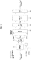
- FIG. 1 illustrates SC-FDMA and OFDMA schemes. SC-FDMA and OFDMA are interchangeably used with SC-FDM and OFDM, respectively.
- FIG. 1 is illustrated in terms of a signal processing of a transmitter, and a signal processing of a receiver is performed in reverse order reverse to that show inof FIG. 1 .
- both a UE for transmitting an uplink signal and a BS for transmitting a downlink signal include a serial-to-parallel converter 401, a subcarrier mapper 403, an M-point IDFT module 404, and a cyclic prefix (CP) adder 406.
- the UE for transmitting a signal according to SC-FDMA additionally includes an N-point DFT module 402.
- FIG.2 illustrates a radio frame structure
- FIG. 2(a) illustrates a type-1 radio frame structure for frequency division duplex (FDD).
- a radio frame includes a plurality of (e.g. 10) subframes each of which includes a plurality of (e.g. 2) slots in the time domain. Each subframe has a duration of 1ms and each slot has a duration of 0.5ms.
- a slot includes a plurality of OFDM/SC-FDMA symbols in the time domain and includes a plurality of resource blocks (RBs) in the frequency domain
- FIG. 2(b) illustrates a type-2 radio frame structure for time division duplex (TDD).
- the type-2 radio frame includes 2 half frames. Each half frame includes 5 subframes each of which includes 2 slots.
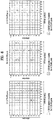
- Table 1 shows UL-DL configurations (Uplink-Downlink Configuration, UL-DL Cfg or UD-cfg) of subframes in a radio frame in the TDD mode.
- Uplink-downlink configuration Downlink-to-Uplink Switch-point periodicity Subframe number 0 1 2 3 4 5 6 7 8 9 0 5 ms D S U U U D S U U U 1 5 ms D S U U D D S U U D 2 5 ms D S U D D D S U D D 3 10 ms D S U U U D D D D D 4 10 ms D S U U D D D D D D 5 10 ms D S U D D D D D D D D 6 5 ms D S U U U U D S U U U D S U U U D S U U D
- D denotes a downlink subframe
- U denotes an uplink subframe
- S denotes a special subframe.
- the special subframe includes DwPTS (Downlink Pilot TimeSlot), GP (Guard Period), and UpPTS (Uplink Pilot TimeSlot).
- DwPTS is a period reserved for downlink transmission
- UpPTS is a period reserved for uplink transmission.
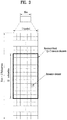
- FIG. 3 illustrates a resource grid of a DL slot.
- a DL slot includes a plurality of OFDMA (or OFDM) symbols in the time domain.
- One DL slot may include 7(6) OFDMA symbols according to cyclic prefix (CP) length, and one resource block (RB) may include 12 subcarriers in the frequency domain.
- Each element on the resource grid is referred to as a resource element (RE).
- One RB includes 12 ⁇ 7(6) REs.
- the number N RB of RBs included in the downlink slot depends on a downlink transmit bandwidth.
- the structure of a UL slot may be same as that of the DL slot except that OFDMA symbols by replaced by SC-FDMA symbols.
- An OFDM(A) symbol and an SC-FDM(A) symbol are referred to as transmission symbols.
- FIG. 4 illustrates a DL subframe structure
- a maximum of three (four) OFDM symbols located in a front portion of a first slot within a subframe correspond to a control region to which a control channel is allocated.
- the remaining OFDM symbols correspond to a data region to which a physical downlink shared chancel (PDSCH) is allocated.
- Examples of DL control channels include a physical control format indicator channel (PCFICH), a physical downlink control channel (PDCCH), a physical hybrid ARQ indicator channel (PHICH), etc.
- the PCFICH is transmitted at a first OFDM symbol of a subframe and carries information regarding the number of OFDM symbols used for transmission of control channels within the subframe.
- the PHICH is a response of uplink transmission and carries an HARQ-ACK signal.
- a PDCCH may carry a transport format and a resource allocation of a downlink shared channel (DL-SCH), resource allocation information of an uplink shared channel (UL-SCH), paging information on a paging channel (PCH), system information on the DL-SCH, information on resource allocation of an upper-layer control message such as a random access response transmitted on the PDSCH, a set of Tx power control commands on individual UEs within an arbitrary UE group, a Tx power control command, information on activation of a voice over IP (VoIP), etc.
- Downlink control information (DCI) is transmitted through the PDCCH.
- DCI formats 0/4 (referred to as UL DCI formats hereinafter) for UL scheduling (or UL grant (UG)) and DCI formats 1/1A/1B/1C/1D/2/2A/2B/2C/2D (referred to as DL DCI formats) DL scheduling are defined.
- the DCI formats selectively include information such as hopping flag, RB allocation, MCS (Modulation Coding Scheme), RV (Redundancy Version), NDI (New Data Indicator), TPC (Transmit Power Control), DMRS (Demodulation Reference Signal) cyclic shift, etc. as necessary.
- a plurality of PDCCHs can be transmitted within a control region.
- a UE monitors the plurality of PDCCHs per subframe in order to check a PDCCH destined therefor.
- the PDCCH is transmitted through one or more control channel elements (CCEs).
- CCEs control channel elements
- a PDCCH coding rate may be controlled by the number of CCEs (i.e. CCE aggregation level) used for PDCCH transmission.
- a CCE includes a plurality of resource element groups (REGs).
- a format of the PDCCH and the number of PDCCH bits are determined by the number of CCEs.
- a BS determines a PDCCH format according to DCI to be transmitted to the UE, and attaches a cyclic redundancy check (CRC) to control information.
- CRC cyclic redundancy check
- the CRC is masked with an identifier (e.g. a radio network temporary identifier (RNTI)) according to an owner or usage of the PDCCH.
- an identifier e.g., cell-RNTI (C-RNTI)
- C-RNTI cell-RNTI
- P-RNTI paging-RNTI
- SIB system information block
- SI-RNTI system information RNTI
- the PDCCH carries a message known as DCI, and a plurality of PDCCHs are generally transmitted at a subframe.
- Each PDCCH is transmitted using one or more control channel elements (CCEs), each of which corresponds to nine REGs.
- CCEs control channel elements
- One REG corresponds to four resource elements (REs).
- REs resource elements
- Four QPSK symbols are mapped into each REG.
- a resource element (RE) reserved by the reference signal (RS) is not included in the REG. Therefore, a total number of REGs within given OFDM symbols are varied depending on the presence of a cell-specific reference signal.
- the REG concept is also used for other downlink control channels (that is, PDFICH and PHICH).
- Four PDCCH formats are supported as listed in Table 2. [Table 2] PDCCH format Number of CCEs ( n ) Number of REGs Number of PDCCH bits 0 1 9 72 1 2 18 144 2 4 36 288 3 8 72 576
- the PDCCH having a format that includes n number of CCEs may start from only CCE having a number equivalent to a multiple of n.
- the number of CCEs used for transmission of a specific PDCCH is determined by the BS in accordance with a channel state. For example, if the PDCCH is for a UE having a good downlink channel (for example, adjacent to BS), one CCE may be required. However, in case of a UE having a poor channel (for example, adjacent to the cell edge), eight CCEs may be required to obtain sufficient robustness. Also, a power level of the PDCCH may be adjusted to correspond to the channel state.
- the LTE system defines a set of CCEs, where the PDCCH may be located for each UE.
- the set of CCEs, where the UE may discover its PDCCH may be referred to as a search space (SS).
- Individual resources within the search space, to which the PDCCH may be transmitted, will be referred to as PDCCH candidates.
- One PDCCH candidate corresponds to 1, 2, 4, or 8 CCEs depending on a CCE aggregation level.
- the BS transmits actual PDCCH (DCI) onto a random PDCCH candidate within the search space, and the UE monitors the search space to discover PDCCH (DCI).
- DCI actual PDCCH
- DCI blind decoding
- the UE tries blind decoding (BD) for the PDCCH candidates within the search space.
- the search space for each PDCCH format may have different sizes.
- a dedicated SS (or UE-specific SS, USS) and a common search space are defined.
- the USS is configured separately for each UE, and the range of the CSS is notified to all UEs.
- the USS and the CSS may be overlapped for the given UE.
- the search spaces may be configured in small size and may overlap each other, it may be impossible for the BS to search for CCE resources for transmitting a PDCCH to all desired UEs within a given subframe. That is, since CCE resources have already been allocated to other UEs, CCE resources for a specific UE may no longer be present in a search space of the specific UE (blocking). In order to minimize the possibility of blocking to be sustained at the next subframe, a UE-specific hopping sequence is applied to the start position of the dedicated search space.
- Table 3 illustrates sizes of the common and dedicated search spaces. [Table 3] PDCCH format Number of CCEs ( n ) Number of candidates in common search space Number of candidates in dedicated search space 0 1 - 6 1 2 - 6 2 4 4 2 3 8 2 2 2
- FIG. 5 illustrates examples of a CRS (Cell-specific Reference Signal) and a DMRS (Demodulation Reference Signal).
- the DMRS is also referred to as a UE-specific RS.
- the CRS is transmitted through maximum 4 antenna ports (e.g., R0 to R3), and used for both channel state measurement and data demodulation.
- the CRS is transmitted without being precoded, and transmitted per subframe on a full-band.
- the DMRS is a user equipment-specific reference signal used to demodulate a signal of each layer in transmitting a signal using multiple antennas.
- the DMRS is used for PDSCH demodulation, and precoded like a layer.
- the DMRS is transmitted only on RB(s) having PDSCH mapped thereto in a subframe scheduled for the PDSCH.
- An LTE-A system supports maximum 8 layers and respective DMRSs therefor.
- the respective DMRSs share the same RE, and are multiplexed according to CDM (Code Division Multiplexing).
- CDM Code Division Multiplexing
- the DMRSs for each layer is spread using a spread code (e.g., a Walsh code, an orthogonal code such as a DFT code) and then multiplexed on the same RE.
- a DMRS for a layer 0 may be spread using [+1 +1]
- a DMRS for a layer 1 may be spread using [+1 -1].
- a DMRS for a layer 2 and a DMRS for a layer 3 are spread on a same RE using orthogonal codes different from each other.
- Antenna port for DMRS includes ⁇ 7, 8, ..., n+6 ⁇ (where, "n" indicates the number of layers).
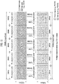
- FIG. 6 illustrates an example of a CSI-RS (Channel Status Information Reference Signal).
- the CSI-RS is used to obtain channel state information.
- the CSI-RS is transmitted in every prescribed transmission period.
- a CSI-RS transmission subframe (hereinafter, referred to as "CSI-RS subframe") is determined by a CSI-RS transmission period and a CSI-RS subframe offset.
- the CSI-RS transmission period and the CSI-RS subframe offset are given by CSI-RS subframe configuration information.
- FIG. 6 (a) shows 20 types of CSI-RS configurations 0 to 19 usable for CSI-RS transmissions by 2 CSI-RS ports, FIG.
- FIG. 6 (b) shows 10 types of CSI-RS configurations 0 to 9 usable by 4 CSI-RS ports
- FIG. 6(c) shows 5 types of CSI-RS configurations 0 to 4 usable by 8 CSI-RS ports.
- the CSI-RS ports correspond to 15 to 22, respectively.
- FIG. 7 illustrates the structure of an uplink subframe.
- a subframe 500 having a length of 1 ms which is a basic unit of uplink transmission includes two slots 501 each having a length of 0.5 ms.
- each slot includes seven symbols 502 and one symbol corresponds to one Single carrier-Frequency Division Multiple Access (SC-FDMA) symbol.
- An RB 503 is a resource allocation unit corresponding to 12 subcarriers in a frequency domain and one slot in a time domain.
- the structure of the uplink subframe of the LTE system is roughly divided into a data region 504 and a control region 505.
- the data region refers to communication resources used for data transmission, such as voice or packets transmitted to each UE, and includes a physical uplink shared channel (PUSCH).
- the control region refers to communication resources used to transmit an uplink control signal such as a downlink channel quality report from each UE, reception ACK/NACK of a downlink signal, an uplink scheduling request or the like, and includes a Physical Uplink Control Channel (PUCCH).
- a sounding reference signal (SRS) is transmitted through a last SC-FDMA symbol of one subframe on a time axis. SRSs of several UEs transmitted through the last SC-FDMA of the same subframe are distinguished according to a frequency position/sequence.
- FIGs. 8 to 9 illustrate slot level structures of PUCCH formats.
- a PUCCH has the following formats in order to transmit control information.
- Table 4 shows modulation schemes according to PUCCH format and the number of bits per subframe.
- Table 5 shows the number of RSs per slot according to PUCCH format and
- Table 6 shows SC-FDMA symbol position in an RS according to PUCCH format.
- PUCCH formats 2a and 2b correspond to normal CP.
- FIG. 8 illustrates PUCCH formats 1a and 1b in case of normal CP.
- PUCCH formats 1a and 1b the same control information is repeated in a subframe on a slot-by-slot basis.
- ACK/NACK signals are respectively transmitted from UEs through different resources configured by different cyclic shifts (CSs) (frequency domain codes) and orthogonal cover codes (OCs or OCCs) (time domain spreading codes) of a computer-generated constant amplitude zero auto correlation (CG-CAZAC) sequence.
- CSs cyclic shifts
- OCCs orthogonal cover codes
- An OC includes a Walsh/DFT orthogonal code, for example.
- Orthogonal sequences w0,w1,w2,w3 may be applied in the arbitrary time domain (after FFT modulation) or in the arbitrary frequency domain (prior to FFT modulation).
- An ACK/NACK resource composed of CS, OC and PRB may be given to a UE through radio resource control (RRC) for SR and persistent scheduling.
- RRC radio resource control
- the ACK/NACK resource may be implicitly provided to the UE by the lowest CCE index of a PUCCH corresponding to a PDSCH for dynamic ACK/NACK and non-persistent scheduling.
- FIG. 9 illustrates PUCCH formats 2/2a/2b in case of normal CP.
- one subframe includes 10 QPSK data symbols in addition to RS symbols in case of normal CP.
- Each of the QPSK symbols is spread in the frequency domain by CS and then mapped to the corresponding SC-FDMA symbol.
- SC-FDMA symbol level CS hopping may be applied to randomize inter-cell interference.
- An RS may be multiplexed by CDM using CSs. For example, if the number of available CSs is 12 or 6, 12 or 6 UEs can be multiplexed in the same PRB. That is, a plurality of UEs can be multiplexed by CS+OC+PRB and CS+PRB in PUCCH formats 1/1a/1b and 2/2a/2b respectively.
- Orthogonal sequences with length-4 and length-3 for PUCCH formats 1/1a/1b are shown in Table 7 and Table 8.
- Table 7 Lenght-4 orthogonal sequences for PUCCH formats 1/1a/1b
- Sequence index n OC ( n S ) Orthogonal sequences w 0 ⁇ w N SF PUCCH ⁇ 1 0 [+1 +1 +1 +1] 1 [+1 -1 +1 -1] 2 [+1 -1 -1 +1]
- Lenght-3 orthogonal sequences for PUCCH formats 1/1a/1b Sequence index n OC ( n S ) Orthogonal sequences w 0 ⁇ w N SF PUCCH ⁇ 1 0 [1 1 1 ] 1 [1 e j 2 ⁇ /3 e j 4 ⁇ /3 ] 2 [1 e j 4 ⁇ /3 e j 2 ⁇ /3 ]
- FIG. 10 illustrates uplink-downlink frame timing relation.
- transmission of the uplink radio frame number i starts prior to (N TA +N TAoffset )*T s seconds from the start of the corresponding downlink radio frame.
- N TAoffset 0 in FDD
- N TAoffset 624 in TDD.
- the value N Taoffset is a value in advance recognized by the BS and the UE. If N TA is indicated through a timing advance command during a random access procedure, the UE adjusts transmission timing of UL signal (e.g., PUCCH/PUSCH/SRS) through the above equation.
- UL transmission timing is set to multiples of 16T s .
- the timing advance command indicates the change of the UL timing based on the current UL timing.
- the timing advance command received at subframe n is applied from the beginning of subframe n+6. In case of FDD, as shown, transmitting timing of UL subframe n is advanced based on the start time of the DL subframe n. On the contrary, in case of TDD, transmitting timing of UL subframe n is advanced based on the end time of the DL subframe n+1 (not shown).
- FIG. 11 illustrates a carrier aggregation (CA) communication system.
- CA carrier aggregation
- an LTE-A system employs CA (or bandwidth aggregation) technology which aggregates a plurality of UL/DL frequency blocks to obtain a wider UL/DL bandwidth.
- Each frequency block is transmitted using a component carrier (CC).
- the CC can be regarded as a carrier frequency (or center carrier, center frequency) for the frequency block.
- a plurality of UL/DL CCs can be aggregated to support a wider UL/DL bandwidth.
- the CCs may be contiguous or non-contiguous in the frequency domain. Bandwidths of the CCs can be independently determined.
- Asymmetrical CA in which the number of UL CCs is different from the number of DL CCs can be implemented. For example, when there are two DL CCs and one UL CC, the DL CCs can correspond to the UL CC in the ratio of 2:1.
- a DL CC/UL CC link can be fixed or semi-statically configured in the system.
- a frequency band that a specific UE can monitor/receive can be limited to M ( ⁇ N) CCs.
- Various parameters with respect to CA can be configured cell-specifically, UE-group-specifically, or UE-specifically.
- Control information may be transmitted/received only through a specific CC.
- This specific CC can be referred to as a Primary CC (PCC) (or anchor CC) and other CCs can be referred to as Secondary CCs (SCCs).
- PCC Primary CC
- SCCs Secondary CCs
- a cell is defined as a combination of DL resources and UL resources. Yet, the UL resources are not mandatory. Therefore, a cell may be composed of DL resources only or both DL resources and UL resources.
- the linkage between the carrier frequencies (or DL CCs) of DL resources and the carrier frequencies (or UL CCs) of UL resources may be indicated by system information when CA is supported.
- a cell operating in primary frequency resources (or a PCC) may be referred to as a primary cell (PCell) and a cell operating in secondary frequency resources (or an SCC) may be referred to as a secondary cell (SCell).
- PCell primary cell
- SCell secondary cell
- the PCell is used for a UE to establish an initial connection or re-establish a connection.
- the PCell may refer to a cell indicated during handover.
- the SCell may be configured after an RRC connection is established and may be used to provide additional radio resources.
- the PCell and the SCell may collectively be referred to as a serving cell. Accordingly, a single serving cell composed of a PCell only exists for a UE in an RRC_Connected state, for which CA is not set or which does not support CA.
- one or more serving cells exist, including a PCell and one or more SCells, for a UE in an RRC_CONNECTED state, for which CA is set.
- Non-cross-CC scheduling corresponds to scheduling in LTE.
- a DL grant PDCCH may be transmitted on DL CC#0 and a PDSCH corresponding thereto may be transmitted on DL CC#2.
- a UL grant PDCCH may be transmitted on DL CC#0 and a PUSCH corresponding thereto may be transmitted on DL CC#4.
- a carrier indicator field is used for cross-CC scheduling. Presence or absence of a CIF in a PDCCH may be semi-statically and UE-specifically (or UE-group-specifically) configured through higher layer signaling (e.g. RRC signaling).
- Scheduling according to the CIF may be arranged as follows.
- the BS may allocate a monitoring DL CC to reduce blind detection complexity of the UE.
- the UE may detect/decode a PDCCH only on the corresponding DL CCs.
- the BS may transmit a PDCCH only through the monitoring DL CC (set).
- the monitoring DL CC set may be UE-specifically, UE-group-specifically or cell-specifically configured.
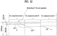
- FIG. 12 illustrates cross-carrier scheduling. While the figure shows DL scheduling, cross-carrier scheduling is equally applied to UL scheduling.
- 3 DL CCs are configured for a UE, and DL CC A may be set as a PDCCH monitoring DL CC.
- each DL CC can transmit only a PDCCH that schedules a PDSCH corresponding to the DL CC without a CIF according to LTE PDCCH rule.
- DL CC A i.e. MCC
- DL CC A can transmit not only a PDCCH that schedules the PDSCH corresponding to the DL CC A but also PDCCHs that schedule PDSCHs of other DL CCs using the CIF.
- a PDCCH is not transmitted in DL CC B/C.
- a specific CC (or cell) used to transmit scheduling information is referred to as “monitoring CC (MCC)" which may be replaced by “monitoring carrier”, “monitoring cell”, “scheduling carrier”, “scheduling cell”, “scheduling CC”, etc.
- MCC monitoring CC
- a DL CC on which a PDSCH corresponding to a PDCCH is transmitted and a UL CC on which a PUSCH corresponding to a PUCCH is transmitted may be referred to as a scheduled carrier, a scheduled CC, a scheduled cell, etc.
- One or more scheduling CCs may be configured per UE.
- a scheduling CC may include a PCC. When only one scheduling CC is configured, the scheduling CC may be the PCC.
- the scheduling CC may be UE-specifically, UE-group-specifically or cell-specifically set.
- an operation scheme for dynamically reconfiguring/changing a UL/DL SF direction for the purpose of performing enhanced interference mitigation and traffic adaptation (i.e., eIMTA) in a TDD status is considered.
- a method of configuring basic UL-DL configuration (UD-cfg) of a TDD cell (or CC) semi-statically using higher layer signaling (e.g., SIB) and then dynamically reconfiguring/changing operation UD-cfg of the corresponding cell (or CC) using lower layer signaling (e.g., L1 (Layer 1) signaling (e.g., PDCCH)) is considered.
- UD-cfg basic UD-cfg
- operation UD-cfg will be referred to as actual-cfg
- Subframe configuration based on UD-cfg is based on Table 1.
- a DL SF, a UL SF, and a special SF will be referred to as D, U and S, respectively.
- actual-cfg may selectively be selected from UD-cfg (including SIB-cfg) which include all of Ds on SIB-cfg. That is, although UD-cfg in which Ds are all arranged in positions of D on SIB-cfg may be determined as actual-cfg, UD-cfg where U is arranged in a position of D on SIB-cfg cannot be determined as actual-cfg. Meanwhile, in eIMTA, reference UD-cfg (hereinafter, D-ref-cfg) may separately be configured by higher layer (signaling) to set HARQ timing (e.g., HARQ-ACK feedback transmission timing) for DL scheduling.
- HARQ timing e.g., HARQ-ACK feedback transmission timing
- actual-cfg may selectively be determined from UD-cfgs (including D-ref-cfg) including all of U on D-ref-cfg. Therefore, UD-cfg where D is arranged in a position of U on D-ref-cfg cannot be determined as actual-cfg.
- D-ref-cfg may be configured as UD-cfg that includes all of Ds on possible actual-cfg candidates
- SIB-cfg may be configured as UD-cfg which include all of Us on possible actual-cfg candidates. That is, D-ref-cfg may be configured as D superset UD-cfg for possible actual-cfg candidates, and SIB-cfg may be configured as U superset UD-cfg for possible actual-cfg candidates.
- Reference UD-cfg (hereinafter, U-ref-cfg) of HARQ timing (e.g., UG/PUSCH/PHICH transmission timing) for UL scheduling may be configured as SIB-cfg.
- U on D-ref-cfg may be considered as fixed U
- D on SIB-cfg may be considered as fixed D
- one of UD-cfg(s) which include all of Ds on SIB-cfg and all of Us on D-ref-cfg may be configured as actual-cfg by L1 signaling.
- eIMTA may be applied in such a manner that some UL SF on UL carrier is reconfigured as DL SF (and/or special SF).
- an operation method for (dynamically) reconfiguring/changing UL SF on UL carrier to specific TDD UL-DL configuration may be considered.
- FIG. 13 illustrates FDD eIMTA scheme based on TDD UD-cfg.
- UL resource of an FDD cell may dynamically be reconfigured using L1 signaling (e.g., PDCCH).
- L1 signaling e.g., PDCCH
- SF configuration of UL CC is reconfigured in accordance with UD-cfg#1. Therefore, PDSCH transmission can be performed on UL CC, whereas PUSCH/PUCCH transmission is restricted.
- L1 signaling e.g., actual-cfg indication information
- for dynamic SF reconfiguration on UL CC may be signaled at a certain period.
- D1 DL SF on DL CC
- D2 reconfigured SF
- a prescribed transmission format e.g., a modulation scheme, etc.
- a (co-channel) interference impact on an adjacent cell and a regulatory condition for each frequency band to limit such an impact
- a case of applying an eIMTA scheme only to one of the two cells can be considered.
- a cell 1 configures UL SF of an SC-FDM scheme on UL CC like an existing method, yet a cell 2 may configure DL SF of an OFDM scheme on the same UL CC based on an existing DL transmission format.
- the cell 1 may receive a strong interference due to an OFDM signal of the cell 2 in terms of UL reception. For this reason, an overall UL reception performance of the cell 1 may be considerably reduced.
- an effective eIMTA operation can be performed while minimizing an (UL) interference impact on an adjacent cell if a slight inter-cell (base station) coordination is accompanied.
- a UL signal e.g., UL data on PUSCH
- a DL signal e.g., DL data on the PUSCH
- the synchronization of the UL/DL signals may mean that reception timings thereof enter CP in viewpoint of the UL reception of the cell 1.
- the orthogonality between the UL/DL signals may mean that their DMRSs are at least distinguished from each other (e.g., CDM).
- a DMRS in DL SF on UL CC may be: 1) transmitted in a similar manner to an existing DL CRS (or a transmission mode for performing DL data reception based thereon) (i.e., transmitted on a full-band in each DL SF UE-commonly) (refer to FIG.
- a DL data transmission on UL CC is set so as to be (cross-CC) scheduled from DL CC.
- the DL data transmission on UL CC is (self-CC) scheduled from the corresponding UL CC, it will be described separately thereafter.
- the specific information includes, for example, transmission timing information (e.g., timing advance) (of a base station) on DL SF (D2) configured on UL CC, configuration parameters (e.g., a base sequence, a sequence group, a cyclic shift, etc.) regarding DL RS (e.g., DMRS, SRS, etc.) transmitted (from the base station) in the DL SF (D2) CP length information (e.g., normal CP, extended CP) applied to the DL SF (D2), and the like.
- transmission timing information e.g., timing advance
- D2 DL SF
- configuration parameters e.g., a base sequence, a sequence group, a cyclic shift, etc.
- DL RS e.g., DMRS, SRS, etc.
- CP length information e.g., normal CP, extended CP
- a DMRS used for a UL transmission format (e.g., PUSCH) is transmitted from a base station to a user equipment through DL SF (D2) configured on UL CC through a full BW (bandwidth) of the corresponding UL CC in every DL SF in a UE-common manner.
- D2 configuration information for example, sequence/cyclic shift information configuring DMRS, an index of a DMRS transmission symbol in DL SF, the number/information of base station antenna ports and the like may be configured identical to parameters applied to an existing UL transmission (refer to FIG. 7 ).
- DMRS (D2) may be mapped contiguously across the full BW in a fourth transmission symbol of each slot in every D2 on UL CC.
- a DMRS (D1) transmitted through DL SF on DL CC is transmitted only in an SF/RB scheduled for data, and mapped by being distributed.
- the DMRS (D2) configuration information for example, the sequence/cyclic shift information configuring DMRS, the index of DMRS transmission symbol in DL SF, the number/information of base station antenna ports and the like may be set beforehand through an upper layer signaling (e.g., RRC (Radio Resource Control)).
- RRC Radio Resource Control
- an RE mapping rule e.g., time priority mapping
- a modulation scheme e.g., SC-FDM with DFT-precoding
- the DMRS may be used for the purposes of a reception/demodulation of DL data on the D2, a measurement/report on CSI (e.g., RI, PMI, CQI) and RRM (Radio Resource Management) (e.g., RSRP (Received Signal Received Power)), an RSRQ (Received Signal Received Quality), an RSSI (Received Signal Strength Indication)) regarding the D2, and/or the like.
- CSI e.g., RI, PMI, CQI
- RRM Radio Resource Management
- RSRP Receiveived Signal Received Power
- RSRQ Receiveived Signal Received Quality
- RSSI Received Signal Strength Indication
- an RE mapping rule e.g., frequency priority mapping
- a modulation scheme e.g., OFDM
- a DL transmission format e.g., PDSCH
- CRS/DMRS shown in FIG. 5 may be used, and for the purposes of a measurement/report on CSI (e.g., RI, PMI, CQI), RRM (e.g., RSRP, RSRQ, RSSI) regarding the D1 and the like, CRS/CSI-RS shown in FIG. 5 and FIG. 6 may be used.
- DMRS configured in the DL SF (D2) on the UL CC may also be transmitted through a plurality of (base station) antenna ports.
- a DMRS transmitted PRB (Physical RB) index, a sub-carrier index (e.g., transmission comb), a cyclic shift and an orthogonal cover code may be set different between DMRSs (D2) transmitted through different antenna ports.
- a BW on the UL CC may be divided into a plurality of PRB sets, and each of the PRB sets may be allocated to a DMRS (D2) transmission of a corresponding antenna port.
- each of the PRB sets may include a (A*n+B)th PRB.
- A indicates a gap between neighboring PRBs in a PRB set
- B indicates a PRB offset given according to the PRB set
- “n” may be “0, 1, ..., N-1”
- “N” indicates the number of PRBs in the PRB set.
- a and B may be changed according to the number of antenna ports used for the DMRS (D2) transmission.
- “A” may be "M (e.g., 2)”
- “B” may have a value among "0, ..., M-1” according to DMRS (D2) antenna port.
- DMRS configured in the DL SF (D1) on the DL CC is mapped to a scheduled PRB all irrespective of an antenna port.
- at least one of group hopping, sequence hopping and cyclic shift (slot) hopping may be applied to the DMRS (D2).
- DFT-precoding may be applied across a frequency band (i.e., an RB set) allocated to a corresponding data transmission (refer to SC-FDMA shown in FIG. 1 ).
- the DFT-precoding is not performed on the frequency band (i.e., the RB set) allocated to the corresponding data transmission.
- a DMRS sequence may be generated by a unit of a single RB or specific N RBs.
- N may be set to the number of base station transmission antenna ports or a multiple of the number in consideration of FDM between base station transmission antenna ports. Or, a value of "N” may be set directly by the base station through an upper layer signaling (e.g., RRC).
- RRC upper layer signaling
- a DMRS sequence is generated on the basis of a full BW of the DL CC, and then mapped to a PRB having a scheduled portion of an entire DMRS sequence.
- a resource allocation i.e., RA
- D DL SF
- the following methods can be considered. If the following method "1)" is used for the DL data transmission/scheduling in the D2, the user equipment may differently interpret resource allocation information in DCI according to whether DL data is scheduled on a prescribed one of DL CC and UL CC. On the other hand, if the following method "2)" is used for the DL data transmission/scheduling in the D2, the user equipment may interpret the resource allocation information in the DCI according to a DL RA type irrespective of whether the DL data is scheduled on a prescribed CC.
- RA resource allocation
- a DMRS used for a UL transmission format is transmitted only through a DL SF/frequency resource (e.g., a (contiguous) RB set) on which DL data is scheduled from a base station to a user equipment through DL SF (D2) configured on UL CC in a UE-specific manner.
- DL SF/frequency resource e.g., a (contiguous) RB set
- D2 configuration information for example, sequence/cyclic shift information configuring DMRS, an index of a DMRS transmission symbol in DL SF, the number/information of base station antenna ports and the like may be configured identical to parameters applied to an existing UL transmission (refer to FIG. 7 ).
- DMRS (D2) may be contiguously mapped only in an RB set having DL data transmitted in a 4 th transmission symbol of each slot within DL SF having DL data transmitted therein.
- DMRS (D1) transmitted through DL SF on DL CC is transmitted only in an SF/RB scheduled for data, and mapped by being distributed.
- the DMRS (D2) configuration information for example, the sequence/cyclic shift information configuring DMRS, the index of DMRS transmission symbol in DL SF, the number/information of base station antenna ports and the like may be set beforehand through an upper layer signaling (e.g., RRC).
- a cyclic shift value applied to the DMRS (D2) or information for inferring such a value may be signaled UE-specifically through DCI having transmitted for DL data scheduling (e.g., explicit signaling through a DMRS cyclic shift field or implicit signaling according to another field value (combination)).
- the number/information of base station antenna ports can be UE-specifically signaled through DCI in a similar manner.
- DL data transmitted through DL SF (D2) on UL CC an RE mapping rule and a modulation scheme used for a UL transmission format (e.g., PUSCH) may be identically applied.
- DMRS (D2) is used only for a reception and modulation of DL data (D2).
- a channel measurement on DL SF on UL CC may be performed using a separate RS, as described below, or inferred indirectly using an uplink channel measurement on the UL CC.
- a DMRS configured in DL SF (D2) on UL CC may also be transmitted through a plurality of (base station) antenna ports.
- D2 DMRS transmitted PRB
- a sub-carrier index e.g., transmission comb
- a cyclic shift and an orthogonal cover code may be set different.
- a BW on UL CC may be divided into a plurlaity of PRB sets, and each of the PRB sets may be allocated to a DMRS (D2) transmission of a corresponding antenna port.
- each of the PRB sets may include a (A*n+B) th PRB.
- A indicates a gap between neighboring PRBs in a PRB set
- B indicates a PRB offset given according to the PRB set.
- n may be “0, 1, ..., N-1”
- N indicates the number of PRBs in the PRB set.
- A” and “B” may be changed according to the number of antenna ports used for the DMRS (D2) transmission.
- A may be "M (e.g., 2)”
- B may have a value among "0, ..., M-1” according to the DMRS (D2) antenna port.
- all DMRS configured in DL SF (D1) on DL CC is mapped to PRB scheduled irrespective of an antenna port.
- at least one of group hopping, sequence hopping, and cyclic shift (slot) hopping may be applied to the DMRS (D2).
- DFT-precoding may be applied across a frequency band (i.e., an RB set) allocated to a corresponding data transmission (refer to SC-FDMA shown in FIG. 1 ).
- DFT-precoding is not performed across a frequency band (i.e., RB set) allocated to a corresponding data transmission.
- a DMRS sequence may be generated in accordance with a length of an RB section allocated to DL data transmission.
- a DMRS sequence is generated with reference to a full BW of the DL CC, and then mapped to a PRB having a scheduled portion of overall whole DMRS sequence.
- the RA scheme applied to the existing UL PUSCH scheduling or the existing DL PDSCH scheduling for DL data transmission/scheduling in a DL SF configured on UL CC may also be used as described in Approach 1.
- an SRS used for UL channel sounding may be transmitted from a base station to a user equipment through DL SF (D2) configured on UL CC with a specific period in a UE-common manner.
- SRS (D2) configuration information for example, sequence/cyclic shift information for configuring SRS, a transmission comb, a transmission period, an index of a SRS transmission symbol in DL SF and the like may be configured identical to parameters applied to an existing UL transmission (refer to FIG. 7 ).
- SRS (D2) may be transmitted in a last transmission symbol of a second slot in a closet DL SF (D2) after an SF corresponding to a transmission period on the UL CC.
- the SRS (D2) may be mapped to an even-numbered sub-carrier or an odd-numbered sub-carrier on a SRS transmission band according to a transmission comb.
- a CRS/CSI-RS transmitted through DL SF on DL CC is transmitted across a full BW in every SF/periodically, and mapped by being distributed within the corresponding SF.
- the SRS (D2) may be used for the purposes of a measurement/report on CSI and RRM regarding the DL SF (D2) configured on the UL CC.
- DL data may not be mapped to a transmission symbol having the SRS transmitted in the DL SF (D2).
- an SRS configured in the DL SF (D2) on the UL CC may be transmitted through a plurality of (base station) antenna ports as well.
- at least one of a DMRS transmitted PRB index, a sub-carrier index (e.g., transmission comb), SF timing, and a cyclic shift applied to SRS can be set different.
- a BW on UL CC may be divided into a plurality of PRB sets, and each of the PRB sets may be allocated to an SRS (D2) transmission of a corresponding antenna port.
- each of the PRB sets may include a (A*n+B)th PRB.
- A indicates a gap between neighboring PRBs in a PRB set
- B indicates a PRB offset given according to the PRB set.
- n may be "0, 1, ..., N-1”
- “N” indicates the number of PRBs in the PRB set.
- A” and “B” may be changed according to the number of antenna ports used for the SRS (D2) transmission.
- A may be "M (e.g., 2)", and "B” may have a value among "0, ..., M-1" according to an SRS (D2) antenna port.
- an SRS configured in the DL SF (D1) on the DL CC shares a PRB set irrespective of an antenna port, and transmission comb and/or cyclic shift is set different according to the antenna port.
- at least one of group hopping, sequence hopping and cyclic shift (slot) hopping may be applied to the DMRS (D2).
- an SRS transmitted periodically through DL SF (D2) configured on UL CC since the signal is transmitted from a base station to a user equipment for a CSI/RRM measurement usage and a report usage regarding the DL SF (D2), it may be transmitted on a full BW of the corresponding UL CC through a single timing (e.g., transmission timing). And, by considering a resource to be used for an interference measurement usage, a zero-power SRS may be configured with a specific period (across the full BW). Between SRSs (D) (and/or SRSs (D) transmitted for different usages), at least one of a PRB index, a sub-carrier index and an SF timing may be set different.
- an SRS sequence may be generated by a unit of a single RB or specific N RBs.
- N may be set to the number of base station transmission antenna ports or a multiple of the number in consideration of FDM between the base station transmission antenna ports. Or, a value of "N" may be directly set by the base station through an upper layer signaling (e.g., RRC).
- a DL data transmission on UL CC is set so as to be (e.g., self-CC) scheduled from the corresponding UL CC
- transmission symbol(s) e.g., 2 transmission symbols, that is, 2nd and 3rd transmission symbols or 5th and 6th transmission symbols in a slot
- DMRS transmission symbol e.g., a 4 th transmission symbol in the slot
- a search space for DCI detection may be configured in form of additionally using a symbol having a next lowest symbol index. For example, if a transmission symbol index in a slot starts from "0", a transmission symbol #1 and a transmission symbol #2 may be preferentially used for DCI transmission, and if a DCI coding rate is low, a transmission symbol #4 and a transmission symbol #5 may be additionally used. Hence, the user equipment may attempt DCI detection in the transmission symbol #1 and the transmission symbol #2, and subsequently attempt DCI detection in the transmission symbols #1, #2, #4, and #5.
- a plurality of subsets may be configured from the transmission symbols #1, #2, #4, and #5, and each of the subsets may be configured as a search space for a DCI detection usage.
- DCI may be set so as to be transmitted only in a first slot, or in both two slots of a subframe.
- a frequency band for the DCI detection may be limited to a portion of a full BW, which may be allocated through an upper layer (e.g., RRC) signaling or an L1 signaling for indicating SF reconfiguration on UL CC.
- a symbol closest to a DMRS transmission symbol e.g., 4 th transmission symbol in a slot
- a 3 rd transmission symbol and a 5 th transmission symbol in the slot are preferentially used for DCI transmission
- a 2 nd transmission symbol and a 6 th transmission symbol may be preferentially used according to a DCI coding rate (reduction).
- a search space for DCI detection (capable of having various coding rates) may be configured in form of additionally using a symbol having a next closest symbol index.
- a transmission symbol #2 and a transmission symbol #4 may be preferentially used for DCI transmission, and if the DCI coding rate is low, a transmission symbol #1 and a transmission symbol #5 may be additionally used.
- a user equipment may attempt DCI detection in the transmission symbol #2 and the transmission symbol #4, and subsequently attempt the DCI detection in the transmission symbols #1, #2, #4 and #5.
- a plurality of subsets may be configured from the transmission symbols #1, #2, #4, and #5, and each of the subsets may be configured as a search space for a DCI detection usage.
- DCI may be set so as to be transmitted only in a first slot, or in both two slots of a subframe.
- a frequency band for the DCI detection may be limited to a portion of a full BW, which may be allocated through upper layer (e.g., RRC) signaling or L1 signaling for indicating SF reconfiguration on UL CC.
- a DL grant DCI for scheduling DL data transmission (for a user equipment) in the corresponding DL SF may be configured/transmitted.
- a PUCCH resource e.g., a PUCCH resource index set
- a PUSCH resource e.g., an RB set
- L1 signaling for indicating SF reconfiguration on UL CC.
- a UL data transmission on UL CC may be set so as to be (cross-CC) scheduled from DL CC.
- DL/UL data transmission on a single same CC may be set so as to be scheduled from different CCs.
- a user equipment may perform only a DL DCI detection operation in DL SF (D2) on UL CC, and omit a UL DCI detection operation.
- the user equipment may perform both of the DL DCI detection operation and the UL DCI detection operation in DL SF (D1) on DL CC.
- This DL/UL scheduling setting method may be identically applied to an FDD eIMTA situation of configuring DL SF on UL CC based on an existing DL transmission format of applying an OFDM scheme as well.
- DL signal transmission allocation in an existing DL SF based on an OFDM scheme including DL CC may be determined by the following parameters.
- a base station determines a DL transmission power per RE.
- a user equipment assumes that a CRS RS EPRE (Energy Per Resource Element) (i.e., P_R) is uniform across a DL full BW, and that until receiving new CRS power information, the CRS RS EPRE is uniform across all subframes.
- the CRS RS EPRE can be inferred on the basis of a parameter (e.g., a Reference Signal Power) provided by upper layer (e.g., RRC) signaling.
- a ratio of PDSCH EPRE to CRS RS EPRE i.e., PDSCH EPRE/CRS RS EPRE
- PDSCH EPRE/CRS RS EPRE is set different in consideration of CRS distribution.
- one of P_A and P_B may be determined by inferring from the parameter provided by the upper layer (e.g., RRC) signaling, and the other may be determined using the ratio thereof.
- P_A/P_B may have various values such as "1, 4/5, 3/5, 2/5" according to the CRS distribution (e.g. the number of antenna ports).
- DL power allocation in a DL SF configured on UL CC may be performed by defining/setting parameters for Approach 1 and Approach 2 as shown below.
- the aforementioned parameters that is, parameters P_Rxx, P_Axx and P_Bxx proposed below may be substituted with P_R, P_A and P_B, respectively.
- the following methods may be considered according to a presence or non-presence of a CRS transmission in the corresponding DL SF.
- a setting of P_R on the UL CC may be omitted.
- a codebook for an MIMO precoding (and a corresponding CSI feedback) in DL SF (D2) (on UL CC) configured in an existing UL transmission format based on a SC-FDM scheme
- Approach 1 the following Approach "1)" is used for the MIMO precoding (and the corresponding CSI feedback) in D2
- the user equipment may differently apply a codebook for an MIMO signal processing (and the corresponding CSI feedback) regarding DL data according to whether DL data/DL RS is received on a prescribed one of DL CC and UL CC.
- the user equipment may perform the MIMO signal processing (and the corresponding CSI feedback) regarding the DL data using the existing codebook used for DL.
- the user equipment may perform the MIMO signal processing (and the corresponding CSI feedback) regarding the DL data using the existing codebook used for UL.
- the user equipment may perform the MIMO signal processing (and the corresponding CSI feedback) regarding the DL data by applying the existing codebook used for DL irrespective of whether the DL data/DL RS is received on a prescribed CC.
- a corresponding precoding and feedback operation e.g., user equipment's PMI (Precoding Matrix Index) selection, base stations's T-PMI (Transmitted PMI) indication, etc.
- PMI Precoding Matrix Index
- T-PMI Transmitted PMI
- the special SF is configured between DL SF (D2) and UL SF on UL CC. If a DwPTS section in the special SF is set small (e.g., configured with 3 or less SC-FDM symbols) so as not to include any DMRS transmission symbol (e.g., a 4 th SC-FDM symbol in a slot) at all, the following methods can be considered.
- the proposed methods of the present invention may not be limited to the FDD eIMTA only, and may be similarly and extensively applicable to a TDD eIMTA scheme in form of reconfiguring/reorganizing UL SF into DL SF (or S SF) on a single CC having both DL SF and UL SF configured thereon.
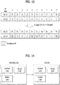
- FIG. 14 illustrates a BS and a UE of a wireless communication system, which are applicable to embodiments of the present invention.
- the wireless communication system includes a relay
- the BS or UE can be replaced by the relay.
- a wireless communication system includes a BS 110 and a UE 120.
- the BS includes a processor 112, a memory 114, an RF unit 116.
- the processor 112 may be configured to implement the procedures and/or methods proposed by the present invention.
- the memory 114 is connected to the processor 112 and stores information related to operations of the processor 112.
- the RF unit 116 is connected to the processor 112, transmits and/or receives an RF signal.
- the UE 120 includes a processor 122, a memory 124, and an RF unit 126.
- the processor 112 may be configured to implement the procedures and/or methods proposed by the present invention.
- the memory 124 is connected to the processor 122 and stores information related to operations of the processor 122.
- the RF unit 126 is connected to the processor 122, transmits and/or receives an RF signal.
- the BS 110 and/or UE 120 may include a single antenna or multiple antennas.
- a description is made centering on a data transmission and reception relationship among a BS, a relay, and an MS.
- a specific operation described as performed by the BS may be performed by an upper node of the BS.
- various operations performed for communication with an MS may be performed by the BS, or network nodes other than the BS.
- the term 'BS' may be replaced with the term 'fixed station', 'Node B', 'enhanced Node B (eNode B or eNB)', 'access point', etc.
- the term 'UE' may be replaced with the term 'Mobile Station (MS)', 'Mobile Subscriber Station (MSS)', 'mobile terminal', etc.
- the embodiments of the present invention may be achieved by various means, for example, hardware, firmware, software, or a combination thereof.
- the methods according to the embodiments of the present invention may be achieved by one or more Application Specific Integrated Circuits (ASICs), Digital Signal Processors (DSPs), Digital Signal Processing Devices (DSPDs), Programmable Logic Devices (PLDs), Field Programmable Gate Arrays (FPGAs), processors, controllers, microcontrollers, microprocessors, etc.
- ASICs Application Specific Integrated Circuits
- DSPs Digital Signal Processors
- DSPDs Digital Signal Processing Devices
- PLDs Programmable Logic Devices
- FPGAs Field Programmable Gate Arrays
- processors controllers, microcontrollers, microprocessors, etc.
- the embodiments of the present invention may be implemented in the form of a module, a procedure, a function, etc.
- software code may be stored in a memory unit and executed by a processor.
- the memory unit is located at the interior or exterior of the processor and may transmit and receive data to and from the processor via various known means.
- the present invention can be used for a UE, a BS or other devices (e.g., relays) in a wireless mobile communication system. Specifically, the present invention is applicable to a method for transmitting control information and an apparatus therefor.
Landscapes
- Engineering & Computer Science (AREA)
- Signal Processing (AREA)
- Computer Networks & Wireless Communication (AREA)
- Quality & Reliability (AREA)
- Mobile Radio Communication Systems (AREA)
Claims (8)
- Procédé permettant à un équipement d'utilisateur (120) de recevoir un signal de liaison descendante, DL, par l'intermédiaire d'une cellule de duplexage par répartition de fréquence, FDD, comprenant une porteuse composante, CC, de liaison montante, UL, et une CC DL dans un système de communication sans fil, le procédé comprenant :la réception d'informations de reconfiguration de sous-trame, SF, relatives à la CC UL, dans lequel les informations de reconfiguration de SF indiquent une SF UL reconfigurée en tant qu'une SF DL sur la CC UL ; etla réception de données de DL sur la cellule FDD,dans lequel, si les données de DL sont reçues dans une SF DL sur la CC DL, les données de DL sont traitées en fonction d'un schéma de multiplexage par répartition de fréquence orthogonale, OFDM, etdans lequel, si les données de DL sont reçues dans une SF DL reconfigurée à partir d'une SF UL en fonction des informations de reconfiguration de SF sur la CC UL, les données de DL sont traitées en fonction d'un schéma de multiplexage par répartition de fréquence à porteuse unique, SC-FDM.
- Procédé selon la revendication 1, dans lequel, si les données de DL sont reçues dans la SF DL sur la CC DL, un signal de référence de démodulation, DMRS, pour les données de DL est mappé en étant distribué à l'intérieur de la SF DL, et dans lequel, si les données de DL sont reçues dans la SF DL reconfigurée sur la CC UL, le DMRS pour les données de DL est mappé de manière contiguë à un symbole de transmission spécifique dans la SF DL reconfigurée.
- Procédé selon la revendication 2, comprenant en outre la réception d'un canal de commande de liaison descendante physique, PDCCH, comprenant des informations de programmation relatives aux données de DL,
dans lequel, si le PDCCH est reçu dans la SF DL sur la CC DL, le PDCCH est mappé à des premiers symboles de transmission P dans la SF DL, et
dans lequel, si le PDCCH est reçu dans la SF DL reconfigurée sur la CC UL, le PDCCH est mappé à un symbole de transmission adjacent du symbole de transmission spécifique auquel le DMRS est mappé de manière contiguë dans la SF DL reconfigurée. - Procédé selon la revendication 1, comprenant en outre la réception d'un signal de référence d'informations d'état de canal, CSI-RS, sur la cellule FDD,
dans lequel, si le CSI-RS est reçu dans la SF DL sur la CC DL, le CSI-RS est mappé en étant distribué à l'intérieur de la SF DL, et
dans lequel, si le CSI-RS est reçu dans la SF DL reconfigurée sur la CC UL, le CSI-RS est mappé à un dernier symbole de transmission dans la SF DL reconfigurée. - Equipement d'utilisateur (120) configuré pour recevoir un signal de liaison descendante, DL, par l'intermédiaire d'une cellule de duplexage par répartition de fréquence, FDD, comprenant une porteuse composante, CC, de liaison montante, UL, et une CC DL, l'équipement d'utilisateur comprenant :une unité de radiofréquences, RF ; etun processeur,dans lequel le processeur est configuré pour effectuer la réception d'informations de reconfiguration de sous-trame, SF, relatives à la CC UL, les informations de reconfiguration de SF indiquant une SF UL reconfigurée en tant qu'une SF DL sur la CC UL, et la réception de données de DL sur la cellule FDD,dans lequel, si les données de DL sont reçues dans une SF DL sur la CC DL, les données de DL sont traitées en fonction d'un schéma de multiplexage par répartition de fréquence orthogonale, OFDM, etdans lequel, si les données de DL sont reçues dans une SF DL reconfigurée à partir d'une SF UL en fonction des informations de reconfiguration de SF sur la CC UL, les données de DL sont traitées en fonction d'un schéma de multiplexage par répartition de fréquence à porteuse unique, SC-FDM.
- Equipement d'utilisateur selon la revendication 5, dans lequel, si les données de DL sont reçues dans la SF DL sur la CC DL, un signal de référence de démodulation, DMRS, pour les données de DL est mappé en étant distribué à l'intérieur de la SF DL, et dans lequel, si les données de DL sont reçues dans la SF DL reconfigurée sur la CC UL, le DMRS pour les données de DL est mappé de manière contiguë à un symbole de transmission spécifique dans la SF DL reconfigurée.
- Equipement d'utilisateur selon la revendication 6, dans lequel le processeur est en outre configuré pour effectuer la réception d'un canal de commande de liaison descendante physique, PDCCH, comprenant des informations de programmation relatives aux données de DL, dans lequel, si le PDCCH est reçu dans la SF DL sur la CC DL, le PDCCH est mappé à des premiers symboles de transmission P dans la SF DL, et dans lequel, si le PDCCH est reçu dans la SF DL reconfigurée sur la CC UL, le PDCCH est mappé à un symbole de transmission adjacent du symbole de transmission spécifique auquel le DMRS est mappé de manière contiguë dans la SF DL reconfigurée.
- Equipement d'utilisateur selon la revendication 5, dans lequel le processeur est en outre configuré pour effectuer la réception d'un signal de référence d'informations d'état de canal, CSI-RS, sur la cellule FDD, dans lequel, si le CSI-RS est reçu dans la SF DL sur la CC DL, le CSI-RS est mappé en étant distribué à l'intérieur de la SF DL, et dans lequel, si le CSI-RS est reçu dans la SF DL reconfigurée sur la CC UL, le CSI-RS est mappé à un dernier symbole de transmission dans la SF DL reconfigurée.
Applications Claiming Priority (2)
| Application Number | Priority Date | Filing Date | Title |
|---|---|---|---|
| US201462012961P | 2014-06-16 | 2014-06-16 | |
| PCT/KR2015/006073 WO2015194825A1 (fr) | 2014-06-16 | 2015-06-16 | Procédé et dispositif pour émettre un signal de liaison descendante dans un système de communication sans fil |
Publications (3)
| Publication Number | Publication Date |
|---|---|
| EP3157188A1 EP3157188A1 (fr) | 2017-04-19 |
| EP3157188A4 EP3157188A4 (fr) | 2018-02-21 |
| EP3157188B1 true EP3157188B1 (fr) | 2018-10-10 |
Family
ID=54935754
Family Applications (1)
| Application Number | Title | Priority Date | Filing Date |
|---|---|---|---|
| EP15809603.2A Active EP3157188B1 (fr) | 2014-06-16 | 2015-06-16 | Procédé et dispositif pour émettre un signal de liaison descendante dans un système de communication sans fil |
Country Status (4)
| Country | Link |
|---|---|
| US (1) | US10506572B2 (fr) |
| EP (1) | EP3157188B1 (fr) |
| CN (1) | CN106664176B (fr) |
| WO (1) | WO2015194825A1 (fr) |
Families Citing this family (15)
| Publication number | Priority date | Publication date | Assignee | Title |
|---|---|---|---|---|
| US20180359044A1 (en) * | 2015-12-01 | 2018-12-13 | Nokia Solutions And Networks Oy | Transmission of synchronization information |
| US10123347B2 (en) * | 2015-12-04 | 2018-11-06 | Qualcomm Incorporated | Method and apparatus for decoupling uplink latency using common uplink burst in TDD subframe structure |
| KR20170078530A (ko) * | 2015-12-29 | 2017-07-07 | 한국전자통신연구원 | 비면허 대역의 무선 통신 시스템에서 사운딩 참조 신호를 전송하는 방법 및 장치, 그리고 사운딩 참조 신호의 전송을 트리거하는 방법 및 장치 |
| JP2019080085A (ja) * | 2016-03-18 | 2019-05-23 | シャープ株式会社 | 端末装置、基地局装置、通信方法、および、集積回路 |
| CN107635286B (zh) * | 2016-07-18 | 2024-04-02 | 北京三星通信技术研究有限公司 | 一种数据或控制信息的加扰和解扰的方法与设备 |
| US10476642B2 (en) * | 2016-09-30 | 2019-11-12 | Qualcomm Incorporated | Reference signal design |
| US11304190B2 (en) * | 2016-11-08 | 2022-04-12 | Qualcomm Incorporated | Search space design and use |
| US11336413B2 (en) | 2017-05-04 | 2022-05-17 | Lg Electronics Inc. | Method for transmitting/receiving reference signal in wireless communication system, and device therefor |
| CA3066293C (fr) | 2017-06-08 | 2022-06-28 | Guangdong Oppo Mobile Telecommunications Corp., Ltd. | Procede de transmission de donnees, dispositif terminal et dispositif de reseau |
| IL271945B2 (en) * | 2017-07-13 | 2024-02-01 | Ntt Docomo Inc | A transmitting device, a receiving device and a method of radio communication |
| US20190053237A1 (en) * | 2017-08-11 | 2019-02-14 | Qualcomm Incorporated | Carrier switching for multiple carriers using the same components of a component path |
| CN110049510B (zh) * | 2018-01-16 | 2021-01-15 | 中国移动通信有限公司研究院 | 交叉链路干扰测量通知方法、网络侧设备及移动通信终端 |
| US10856284B2 (en) * | 2018-02-16 | 2020-12-01 | Qualcomm Incorporated | Resource allocation for a short transmission time interval (STTI) system |
| EP3910861A4 (fr) * | 2019-02-15 | 2022-03-23 | Samsung Electronics Co., Ltd. | Procédé et dispositif de transmission et de réception de signal de référence dans un système de communication sans fil par ondes millimétriques |
| US11706074B2 (en) * | 2020-02-26 | 2023-07-18 | Qualcomm Incorporated | Channel occupancy time based radio link measurements and radio resource measurements in shared spectrum |
Family Cites Families (24)
| Publication number | Priority date | Publication date | Assignee | Title |
|---|---|---|---|---|
| CN101505180B (zh) * | 2009-03-17 | 2013-12-04 | 中兴通讯股份有限公司 | 高级长期演进系统中csi参考信号的承载方法与装置 |
| CN201780605U (zh) * | 2009-04-22 | 2011-03-30 | 万信电子科技有限公司 | 服装试穿系统 |
| US9236992B2 (en) * | 2009-09-18 | 2016-01-12 | Lg Electronics Inc. | Method and apparatus for transceiving scheduling signals in a multi-carrier wireless communication system |
| WO2012109195A2 (fr) * | 2011-02-07 | 2012-08-16 | Interdigital Patent Holdings, Inc. | Procédé et appareil pour faire fonctionner des cellules supplémentaires dans un spectre exempt de licence |
| CN107104767B (zh) * | 2011-03-11 | 2020-06-26 | Lg电子株式会社 | 在无线通信系统中设置动态子帧的方法及其设备 |
| US9042277B2 (en) * | 2011-04-11 | 2015-05-26 | Qualcomm Incorporated | Transmission of control information for FDD-TDD carrier aggregation |
| WO2012148222A2 (fr) * | 2011-04-27 | 2012-11-01 | Lg Electronics Inc. | Procédé et dispositif de transmission d'informations de contrôle dans un système de communication sans fil |
| US8934350B2 (en) * | 2011-05-23 | 2015-01-13 | Qualcomm Incorporated | Channel state information feedback for carrier aggregation with flexible carrier configurations |
| KR20130045169A (ko) * | 2011-10-24 | 2013-05-03 | 주식회사 팬택 | 다중 요소 반송파 시스템에서 상향링크 동기의 수행장치 및 방법 |
| WO2013162333A1 (fr) * | 2012-04-26 | 2013-10-31 | 한국전자통신연구원 | Procédé de communication entre dispositifs utilisant la commande partielle de dispositifs |
| US9930678B2 (en) * | 2012-07-19 | 2018-03-27 | Qualcomm Incorporated | Multiplexing UEs with different TDD configurations and some techniques to mitigate UE-to-UE and base station-to-base station interference |
| CN104662818B (zh) * | 2012-09-21 | 2018-02-09 | Lg电子株式会社 | 用于在无线通信系统中发送和接收下行信号的方法和装置 |
| WO2014054887A1 (fr) * | 2012-10-02 | 2014-04-10 | 한양대학교 산학협력단 | Procédé d'émission et de réception de signal et de canal de liaison descendante, terminal associé et station de base associée |
| US9521664B2 (en) * | 2012-11-02 | 2016-12-13 | Qualcomm Incorporated | EPDCCH resource and quasi-co-location management in LTE |
| US10116422B2 (en) * | 2012-11-02 | 2018-10-30 | Qualcomm Incorporated | Managing cross-carrier scheduling in carrier aggregation with EPDCCH in LTE |
| WO2015061987A1 (fr) * | 2013-10-30 | 2015-05-07 | Qualcomm Incorporated | Indication inter-porteuse de configurations de sous-trames de liaison montante/descendante |
| US9854576B2 (en) * | 2013-12-27 | 2017-12-26 | Sharp Kabushiki Kaisha | Terminal device, base station apparatus, and method |
| CN104753632B (zh) * | 2013-12-31 | 2019-03-15 | 中兴通讯股份有限公司 | 信息处理方法及装置 |
| US9853779B2 (en) * | 2014-01-10 | 2017-12-26 | Sharp Kabushiki Kaisha | Systems and methods for carrier aggregation |
| JP6425890B2 (ja) * | 2014-01-14 | 2018-11-21 | 株式会社Nttドコモ | ユーザ端末、無線基地局および無線通信方法 |
| KR102235637B1 (ko) * | 2014-01-29 | 2021-04-05 | 삼성전자주식회사 | 무선 통신 시스템에서 D2D(Device to Device) 통신의 자원 할당을 통한 송신/수신 단말의 동작 방법 및 장치 |
| WO2015115454A1 (fr) * | 2014-01-30 | 2015-08-06 | シャープ株式会社 | Dispositif de terminal, dispositif de station de base et procédé de communication |
| EP3117637B1 (fr) * | 2014-03-12 | 2017-11-01 | Telefonaktiebolaget LM Ericsson (publ) | Communication de dispositif à dispositif dans un système de communication cellulaire |
| WO2015170935A1 (fr) * | 2014-05-09 | 2015-11-12 | Samsung Electronics Co., Ltd. | Appareil et procédé d'évitement d'interférences dans un système de communications sans fil de dispositif à dispositif |
-
2015
- 2015-06-16 EP EP15809603.2A patent/EP3157188B1/fr active Active
- 2015-06-16 US US15/316,437 patent/US10506572B2/en active Active
- 2015-06-16 CN CN201580031819.7A patent/CN106664176B/zh active Active
- 2015-06-16 WO PCT/KR2015/006073 patent/WO2015194825A1/fr active Application Filing
Non-Patent Citations (1)
| Title |
|---|
| None * |
Also Published As
| Publication number | Publication date |
|---|---|
| EP3157188A1 (fr) | 2017-04-19 |
| WO2015194825A1 (fr) | 2015-12-23 |
| CN106664176B (zh) | 2020-11-24 |
| US10506572B2 (en) | 2019-12-10 |
| EP3157188A4 (fr) | 2018-02-21 |
| US20170201967A1 (en) | 2017-07-13 |
| CN106664176A (zh) | 2017-05-10 |
Similar Documents
| Publication | Publication Date | Title |
|---|---|---|
| US11546195B2 (en) | Method and device for transmitting discovery reference signal in wireless access system supporting unlicensed band | |
| EP3157188B1 (fr) | Procédé et dispositif pour émettre un signal de liaison descendante dans un système de communication sans fil | |
| US11082165B2 (en) | Method and apparatus for transmitting or receiving sub-frame length information in wireless access system supporting non-licensed band | |
| US10862607B2 (en) | Method for transceiving shortened physical downlink shared channel in wireless access system supporting unlicensed band, and device supporting same | |
| US9480050B2 (en) | Method for configuring resource for carrier aggregation and apparatus for same | |
| EP2688239B1 (fr) | Procédé servant à émettre et à recevoir un signal et dispositif associé | |
| US9281930B2 (en) | Method for transmitting/receiving data in wireless access system and base station for same | |
| US9730240B2 (en) | Communication method considering carrier type and apparatus for same | |
| EP2809023B1 (fr) | Procédé de transmission d'informations de commande et appareil correspondant | |
| US20180213386A1 (en) | Method and device for transreceiving discovery reference signal in wireless access system supporting unlicensed band | |
| US20180249499A1 (en) | Method for performing cca in wireless access system supporting unlicensed band, and apparatus for supporting same | |
| US20180270011A1 (en) | Method for transmitting control information, and apparatus therefor | |
| EP2728774A2 (fr) | Procédé et un appareil de contrôle d'une interférence intracellulaire dans un système de communication sans fil | |
| US20140050130A1 (en) | Method for transmitting/receiving data in wireless communication system and base station for same | |
| US9591660B2 (en) | Communication method taking carrier type into consideration, and apparatus therefor | |
| US10314018B2 (en) | Method for transmitting and receiving wireless signal and apparatus therefor | |
| US10455525B2 (en) | Method for transmitting control information, and apparatus therefor | |
| KR20200033345A (ko) | 무선 통신 시스템에서 무선 신호 송수신 방법 및 장치 | |
| US10194422B2 (en) | Signal transmission and reception method in wireless communication system supporting carrier aggregation, and device for same | |
| EP3389205B1 (fr) | Procédé d'émission et de réception de signaux et dispositif associé | |
| US20170339720A1 (en) | Method for performing backoff in wireless connection system that supports unlicensed bands, and apparatus supporting same | |
| US11006440B2 (en) | Method for transmitting/receiving signals, and device for same | |
| US10142978B2 (en) | Method and apparatus for transmitting control information in wireless communication system |
Legal Events
| Date | Code | Title | Description |
|---|---|---|---|
| STAA | Information on the status of an ep patent application or granted ep patent |
Free format text: STATUS: THE INTERNATIONAL PUBLICATION HAS BEEN MADE |
|
| PUAI | Public reference made under article 153(3) epc to a published international application that has entered the european phase |
Free format text: ORIGINAL CODE: 0009012 |
|
| STAA | Information on the status of an ep patent application or granted ep patent |
Free format text: STATUS: REQUEST FOR EXAMINATION WAS MADE |
|
| 17P | Request for examination filed |
Effective date: 20161129 |
|
| AK | Designated contracting states |
Kind code of ref document: A1 Designated state(s): AL AT BE BG CH CY CZ DE DK EE ES FI FR GB GR HR HU IE IS IT LI LT LU LV MC MK MT NL NO PL PT RO RS SE SI SK SM TR |
|
| AX | Request for extension of the european patent |
Extension state: BA ME |
|
| DAV | Request for validation of the european patent (deleted) | ||
| DAX | Request for extension of the european patent (deleted) | ||
| A4 | Supplementary search report drawn up and despatched |
Effective date: 20180124 |
|
| RIC1 | Information provided on ipc code assigned before grant |
Ipc: H04L 5/14 20060101ALI20180118BHEP Ipc: H04L 5/00 20060101AFI20180118BHEP |
|
| GRAP | Despatch of communication of intention to grant a patent |
Free format text: ORIGINAL CODE: EPIDOSNIGR1 |
|
| STAA | Information on the status of an ep patent application or granted ep patent |
Free format text: STATUS: GRANT OF PATENT IS INTENDED |
|
| RIC1 | Information provided on ipc code assigned before grant |
Ipc: H04L 5/14 20060101ALI20180404BHEP Ipc: H04L 5/00 20060101AFI20180404BHEP |
|
| INTG | Intention to grant announced |
Effective date: 20180424 |
|
| GRAS | Grant fee paid |
Free format text: ORIGINAL CODE: EPIDOSNIGR3 |
|
| GRAA | (expected) grant |
Free format text: ORIGINAL CODE: 0009210 |
|
| STAA | Information on the status of an ep patent application or granted ep patent |
Free format text: STATUS: THE PATENT HAS BEEN GRANTED |
|
| AK | Designated contracting states |
Kind code of ref document: B1 Designated state(s): AL AT BE BG CH CY CZ DE DK EE ES FI FR GB GR HR HU IE IS IT LI LT LU LV MC MK MT NL NO PL PT RO RS SE SI SK SM TR |
|
| REG | Reference to a national code |
Ref country code: GB Ref legal event code: FG4D |
|
| REG | Reference to a national code |
Ref country code: CH Ref legal event code: EP Ref country code: AT Ref legal event code: REF Ref document number: 1052505 Country of ref document: AT Kind code of ref document: T Effective date: 20181015 |
|
| REG | Reference to a national code |
Ref country code: IE Ref legal event code: FG4D |
|
| REG | Reference to a national code |
Ref country code: DE Ref legal event code: R096 Ref document number: 602015018045 Country of ref document: DE |
|
| REG | Reference to a national code |
Ref country code: NL Ref legal event code: MP Effective date: 20181010 |
|
| REG | Reference to a national code |
Ref country code: LT Ref legal event code: MG4D |
|
| REG | Reference to a national code |
Ref country code: AT Ref legal event code: MK05 Ref document number: 1052505 Country of ref document: AT Kind code of ref document: T Effective date: 20181010 |
|
| PG25 | Lapsed in a contracting state [announced via postgrant information from national office to epo] |
Ref country code: NL Free format text: LAPSE BECAUSE OF FAILURE TO SUBMIT A TRANSLATION OF THE DESCRIPTION OR TO PAY THE FEE WITHIN THE PRESCRIBED TIME-LIMIT Effective date: 20181010 |
|
| PG25 | Lapsed in a contracting state [announced via postgrant information from national office to epo] |
Ref country code: AT Free format text: LAPSE BECAUSE OF FAILURE TO SUBMIT A TRANSLATION OF THE DESCRIPTION OR TO PAY THE FEE WITHIN THE PRESCRIBED TIME-LIMIT Effective date: 20181010 Ref country code: PL Free format text: LAPSE BECAUSE OF FAILURE TO SUBMIT A TRANSLATION OF THE DESCRIPTION OR TO PAY THE FEE WITHIN THE PRESCRIBED TIME-LIMIT Effective date: 20181010 Ref country code: HR Free format text: LAPSE BECAUSE OF FAILURE TO SUBMIT A TRANSLATION OF THE DESCRIPTION OR TO PAY THE FEE WITHIN THE PRESCRIBED TIME-LIMIT Effective date: 20181010 Ref country code: LT Free format text: LAPSE BECAUSE OF FAILURE TO SUBMIT A TRANSLATION OF THE DESCRIPTION OR TO PAY THE FEE WITHIN THE PRESCRIBED TIME-LIMIT Effective date: 20181010 Ref country code: BG Free format text: LAPSE BECAUSE OF FAILURE TO SUBMIT A TRANSLATION OF THE DESCRIPTION OR TO PAY THE FEE WITHIN THE PRESCRIBED TIME-LIMIT Effective date: 20190110 Ref country code: IS Free format text: LAPSE BECAUSE OF FAILURE TO SUBMIT A TRANSLATION OF THE DESCRIPTION OR TO PAY THE FEE WITHIN THE PRESCRIBED TIME-LIMIT Effective date: 20190210 Ref country code: ES Free format text: LAPSE BECAUSE OF FAILURE TO SUBMIT A TRANSLATION OF THE DESCRIPTION OR TO PAY THE FEE WITHIN THE PRESCRIBED TIME-LIMIT Effective date: 20181010 Ref country code: NO Free format text: LAPSE BECAUSE OF FAILURE TO SUBMIT A TRANSLATION OF THE DESCRIPTION OR TO PAY THE FEE WITHIN THE PRESCRIBED TIME-LIMIT Effective date: 20190110 Ref country code: FI Free format text: LAPSE BECAUSE OF FAILURE TO SUBMIT A TRANSLATION OF THE DESCRIPTION OR TO PAY THE FEE WITHIN THE PRESCRIBED TIME-LIMIT Effective date: 20181010 Ref country code: LV Free format text: LAPSE BECAUSE OF FAILURE TO SUBMIT A TRANSLATION OF THE DESCRIPTION OR TO PAY THE FEE WITHIN THE PRESCRIBED TIME-LIMIT Effective date: 20181010 |
|
| PG25 | Lapsed in a contracting state [announced via postgrant information from national office to epo] |
Ref country code: RS Free format text: LAPSE BECAUSE OF FAILURE TO SUBMIT A TRANSLATION OF THE DESCRIPTION OR TO PAY THE FEE WITHIN THE PRESCRIBED TIME-LIMIT Effective date: 20181010 Ref country code: SE Free format text: LAPSE BECAUSE OF FAILURE TO SUBMIT A TRANSLATION OF THE DESCRIPTION OR TO PAY THE FEE WITHIN THE PRESCRIBED TIME-LIMIT Effective date: 20181010 Ref country code: AL Free format text: LAPSE BECAUSE OF FAILURE TO SUBMIT A TRANSLATION OF THE DESCRIPTION OR TO PAY THE FEE WITHIN THE PRESCRIBED TIME-LIMIT Effective date: 20181010 Ref country code: PT Free format text: LAPSE BECAUSE OF FAILURE TO SUBMIT A TRANSLATION OF THE DESCRIPTION OR TO PAY THE FEE WITHIN THE PRESCRIBED TIME-LIMIT Effective date: 20190210 Ref country code: GR Free format text: LAPSE BECAUSE OF FAILURE TO SUBMIT A TRANSLATION OF THE DESCRIPTION OR TO PAY THE FEE WITHIN THE PRESCRIBED TIME-LIMIT Effective date: 20190111 |
|
| REG | Reference to a national code |
Ref country code: DE Ref legal event code: R097 Ref document number: 602015018045 Country of ref document: DE |
|
| PG25 | Lapsed in a contracting state [announced via postgrant information from national office to epo] |
Ref country code: DK Free format text: LAPSE BECAUSE OF FAILURE TO SUBMIT A TRANSLATION OF THE DESCRIPTION OR TO PAY THE FEE WITHIN THE PRESCRIBED TIME-LIMIT Effective date: 20181010 Ref country code: CZ Free format text: LAPSE BECAUSE OF FAILURE TO SUBMIT A TRANSLATION OF THE DESCRIPTION OR TO PAY THE FEE WITHIN THE PRESCRIBED TIME-LIMIT Effective date: 20181010 Ref country code: IT Free format text: LAPSE BECAUSE OF FAILURE TO SUBMIT A TRANSLATION OF THE DESCRIPTION OR TO PAY THE FEE WITHIN THE PRESCRIBED TIME-LIMIT Effective date: 20181010 |
|
| PLBE | No opposition filed within time limit |
Free format text: ORIGINAL CODE: 0009261 |
|
| STAA | Information on the status of an ep patent application or granted ep patent |
Free format text: STATUS: NO OPPOSITION FILED WITHIN TIME LIMIT |
|
| PG25 | Lapsed in a contracting state [announced via postgrant information from national office to epo] |
Ref country code: RO Free format text: LAPSE BECAUSE OF FAILURE TO SUBMIT A TRANSLATION OF THE DESCRIPTION OR TO PAY THE FEE WITHIN THE PRESCRIBED TIME-LIMIT Effective date: 20181010 Ref country code: SM Free format text: LAPSE BECAUSE OF FAILURE TO SUBMIT A TRANSLATION OF THE DESCRIPTION OR TO PAY THE FEE WITHIN THE PRESCRIBED TIME-LIMIT Effective date: 20181010 Ref country code: EE Free format text: LAPSE BECAUSE OF FAILURE TO SUBMIT A TRANSLATION OF THE DESCRIPTION OR TO PAY THE FEE WITHIN THE PRESCRIBED TIME-LIMIT Effective date: 20181010 Ref country code: SK Free format text: LAPSE BECAUSE OF FAILURE TO SUBMIT A TRANSLATION OF THE DESCRIPTION OR TO PAY THE FEE WITHIN THE PRESCRIBED TIME-LIMIT Effective date: 20181010 |
|
| 26N | No opposition filed |
Effective date: 20190711 |
|
| PG25 | Lapsed in a contracting state [announced via postgrant information from national office to epo] |
Ref country code: SI Free format text: LAPSE BECAUSE OF FAILURE TO SUBMIT A TRANSLATION OF THE DESCRIPTION OR TO PAY THE FEE WITHIN THE PRESCRIBED TIME-LIMIT Effective date: 20181010 |
|
| PG25 | Lapsed in a contracting state [announced via postgrant information from national office to epo] |
Ref country code: MC Free format text: LAPSE BECAUSE OF FAILURE TO SUBMIT A TRANSLATION OF THE DESCRIPTION OR TO PAY THE FEE WITHIN THE PRESCRIBED TIME-LIMIT Effective date: 20181010 |
|
| REG | Reference to a national code |
Ref country code: CH Ref legal event code: PL |
|
| GBPC | Gb: european patent ceased through non-payment of renewal fee |
Effective date: 20190616 |
|
| REG | Reference to a national code |
Ref country code: BE Ref legal event code: MM Effective date: 20190630 |
|
| PG25 | Lapsed in a contracting state [announced via postgrant information from national office to epo] |
Ref country code: TR Free format text: LAPSE BECAUSE OF FAILURE TO SUBMIT A TRANSLATION OF THE DESCRIPTION OR TO PAY THE FEE WITHIN THE PRESCRIBED TIME-LIMIT Effective date: 20181010 |
|
| PG25 | Lapsed in a contracting state [announced via postgrant information from national office to epo] |
Ref country code: GB Free format text: LAPSE BECAUSE OF NON-PAYMENT OF DUE FEES Effective date: 20190616 Ref country code: IE Free format text: LAPSE BECAUSE OF NON-PAYMENT OF DUE FEES Effective date: 20190616 |
|
| PG25 | Lapsed in a contracting state [announced via postgrant information from national office to epo] |
Ref country code: LU Free format text: LAPSE BECAUSE OF NON-PAYMENT OF DUE FEES Effective date: 20190616 Ref country code: BE Free format text: LAPSE BECAUSE OF NON-PAYMENT OF DUE FEES Effective date: 20190630 Ref country code: CH Free format text: LAPSE BECAUSE OF NON-PAYMENT OF DUE FEES Effective date: 20190630 Ref country code: LI Free format text: LAPSE BECAUSE OF NON-PAYMENT OF DUE FEES Effective date: 20190630 |
|
| PG25 | Lapsed in a contracting state [announced via postgrant information from national office to epo] |
Ref country code: FR Free format text: LAPSE BECAUSE OF NON-PAYMENT OF DUE FEES Effective date: 20190630 |
|
| PG25 | Lapsed in a contracting state [announced via postgrant information from national office to epo] |
Ref country code: CY Free format text: LAPSE BECAUSE OF FAILURE TO SUBMIT A TRANSLATION OF THE DESCRIPTION OR TO PAY THE FEE WITHIN THE PRESCRIBED TIME-LIMIT Effective date: 20181010 |
|
| PG25 | Lapsed in a contracting state [announced via postgrant information from national office to epo] |
Ref country code: MT Free format text: LAPSE BECAUSE OF FAILURE TO SUBMIT A TRANSLATION OF THE DESCRIPTION OR TO PAY THE FEE WITHIN THE PRESCRIBED TIME-LIMIT Effective date: 20181010 Ref country code: HU Free format text: LAPSE BECAUSE OF FAILURE TO SUBMIT A TRANSLATION OF THE DESCRIPTION OR TO PAY THE FEE WITHIN THE PRESCRIBED TIME-LIMIT; INVALID AB INITIO Effective date: 20150616 |
|
| PG25 | Lapsed in a contracting state [announced via postgrant information from national office to epo] |
Ref country code: MK Free format text: LAPSE BECAUSE OF FAILURE TO SUBMIT A TRANSLATION OF THE DESCRIPTION OR TO PAY THE FEE WITHIN THE PRESCRIBED TIME-LIMIT Effective date: 20181010 |
|
| PGFP | Annual fee paid to national office [announced via postgrant information from national office to epo] |
Ref country code: DE Payment date: 20230508 Year of fee payment: 9 |