EP3157137A1 - Rotor assembly, motor and dual clutch transmission - Google Patents
Rotor assembly, motor and dual clutch transmission Download PDFInfo
- Publication number
- EP3157137A1 EP3157137A1 EP15807274.4A EP15807274A EP3157137A1 EP 3157137 A1 EP3157137 A1 EP 3157137A1 EP 15807274 A EP15807274 A EP 15807274A EP 3157137 A1 EP3157137 A1 EP 3157137A1
- Authority
- EP
- European Patent Office
- Prior art keywords
- grooves
- rotor assembly
- extension portion
- diameter
- imaginary
- Prior art date
- Legal status (The legal status is an assumption and is not a legal conclusion. Google has not performed a legal analysis and makes no representation as to the accuracy of the status listed.)
- Granted
Links
Images




Classifications
-
- H—ELECTRICITY
- H02—GENERATION; CONVERSION OR DISTRIBUTION OF ELECTRIC POWER
- H02K—DYNAMO-ELECTRIC MACHINES
- H02K1/00—Details of the magnetic circuit
- H02K1/06—Details of the magnetic circuit characterised by the shape, form or construction
- H02K1/22—Rotating parts of the magnetic circuit
- H02K1/27—Rotor cores with permanent magnets
- H02K1/2706—Inner rotors
- H02K1/272—Inner rotors the magnetisation axis of the magnets being perpendicular to the rotor axis
- H02K1/2726—Inner rotors the magnetisation axis of the magnets being perpendicular to the rotor axis the rotor consisting of a single magnet or two or more axially juxtaposed single magnets
- H02K1/2733—Annular magnets
-
- H—ELECTRICITY
- H02—GENERATION; CONVERSION OR DISTRIBUTION OF ELECTRIC POWER
- H02K—DYNAMO-ELECTRIC MACHINES
- H02K1/00—Details of the magnetic circuit
- H02K1/06—Details of the magnetic circuit characterised by the shape, form or construction
- H02K1/22—Rotating parts of the magnetic circuit
- H02K1/27—Rotor cores with permanent magnets
- H02K1/2706—Inner rotors
- H02K1/272—Inner rotors the magnetisation axis of the magnets being perpendicular to the rotor axis
- H02K1/2726—Inner rotors the magnetisation axis of the magnets being perpendicular to the rotor axis the rotor consisting of a single magnet or two or more axially juxtaposed single magnets
-
- F—MECHANICAL ENGINEERING; LIGHTING; HEATING; WEAPONS; BLASTING
- F16—ENGINEERING ELEMENTS AND UNITS; GENERAL MEASURES FOR PRODUCING AND MAINTAINING EFFECTIVE FUNCTIONING OF MACHINES OR INSTALLATIONS; THERMAL INSULATION IN GENERAL
- F16H—GEARING
- F16H3/00—Toothed gearings for conveying rotary motion with variable gear ratio or for reversing rotary motion
- F16H3/02—Toothed gearings for conveying rotary motion with variable gear ratio or for reversing rotary motion without gears having orbital motion
- F16H3/08—Toothed gearings for conveying rotary motion with variable gear ratio or for reversing rotary motion without gears having orbital motion exclusively or essentially with continuously meshing gears, that can be disengaged from their shafts
- F16H3/087—Toothed gearings for conveying rotary motion with variable gear ratio or for reversing rotary motion without gears having orbital motion exclusively or essentially with continuously meshing gears, that can be disengaged from their shafts characterised by the disposition of the gears
- F16H3/091—Toothed gearings for conveying rotary motion with variable gear ratio or for reversing rotary motion without gears having orbital motion exclusively or essentially with continuously meshing gears, that can be disengaged from their shafts characterised by the disposition of the gears including a single countershaft
-
- H—ELECTRICITY
- H02—GENERATION; CONVERSION OR DISTRIBUTION OF ELECTRIC POWER
- H02K—DYNAMO-ELECTRIC MACHINES
- H02K1/00—Details of the magnetic circuit
- H02K1/06—Details of the magnetic circuit characterised by the shape, form or construction
- H02K1/22—Rotating parts of the magnetic circuit
- H02K1/28—Means for mounting or fastening rotating magnetic parts on to, or to, the rotor structures
- H02K1/30—Means for mounting or fastening rotating magnetic parts on to, or to, the rotor structures using intermediate parts, e.g. spiders
-
- F—MECHANICAL ENGINEERING; LIGHTING; HEATING; WEAPONS; BLASTING
- F16—ENGINEERING ELEMENTS AND UNITS; GENERAL MEASURES FOR PRODUCING AND MAINTAINING EFFECTIVE FUNCTIONING OF MACHINES OR INSTALLATIONS; THERMAL INSULATION IN GENERAL
- F16H—GEARING
- F16H3/00—Toothed gearings for conveying rotary motion with variable gear ratio or for reversing rotary motion
- F16H3/006—Toothed gearings for conveying rotary motion with variable gear ratio or for reversing rotary motion power being selectively transmitted by parallel flow paths, e.g. dual clutch transmissions
Definitions
- the present invention relates to a rotor assembly, a motor, and a dual-clutch transmission (DCT) including the same.
- a transmission of a vehicle which is a transmission device manually operated by a clutch operation of a user or automatically operated by a mission depending on speed, is configured to include a motor.
- an interior permanent magnet (IPM)-type motor having a permanent magnet installed in a rotor is used as a motor of a transmission.
- an IPM-type motor uses an NdFeB-based permanent magnet which is lightweight and has strong magnetism, it has an advantage of high efficiency and power density.
- an NdFeB-based permanent magnet includes neodymium (Nd), which is a rare earth, and thus there is a problem of an increase in manufacturing costs of a motor itself due to an increase in price of the rare earth.
- Nd neodymium
- a rare earth-free motor includes a ferrite magnet motor, an induction motor, a reluctance motor, and so on, and the most representative motor of these is the ferrite magnet motor.
- a ferrite magnet motor is a motor using a ferrite magnet, which is a magnetic ceramic, and has an advantage of lower price and easier design than a rare earth motor.
- the present invention is directed to providing a motor which is able to suppress a crack generated in a magnet.
- the rotor assembly may include a ring magnet configured to include an insertion hole in which a shaft is disposed and a plurality of first grooves formed on one surface thereof along a first imaginary circle and a core member configured to include a body portion disposed between the shaft and the insertion hole and an extension portion covering the plurality of first grooves.
- the extension portion may include a plurality of second grooves which are not on a plurality of first imaginary straight lines that respectively pass from a center of the first imaginary circle through the plurality of first grooves.
- the plurality of second grooves may be disposed along a second imaginary circle defined on the extension portion.
- a diameter of the second imaginary circle may be less than a diameter of the first imaginary circle.
- the extension portion may have a diameter greater than a diameter of the first imaginary circle and cover at least a part of one surface and the other surface of the ring magnet.
- the diameter of the first imaginary circle, the diameter of the second imaginary circle, a diameter of the extension portion, and a diameter of the ring magnet may satisfy the following formula 1.
- D1 is the diameter of the first imaginary circle
- D2 is the diameter of the second imaginary circle
- D3 is the diameter of the extension portion
- D4 is the diameter of the ring magnet.
- An axial length of the core member may be greater than a length of the ring magnet.
- the extension portion may include a plurality of third grooves formed on one surface thereof.
- the number of the third grooves may be the same as the number of the first grooves.
- Third imaginary straight lines respectively passing from the center of the first imaginary circle through the third grooves may overlap with the first imaginary straight lines.
- the third imaginary straight lines respectively passing from the center of the first imaginary circle through the third grooves may respectively have a predetermined angle with the first imaginary straight lines.
- the second grooves are respectively disposed not to be on the third imaginary straight lines respectively passing from the center of the first imaginary circle through the third grooves.
- An angle between each of the third imaginary straight lines respectively passing from the center of the first imaginary circle through the third grooves and each of the first straight lines may be less than an angle between each of second imaginary straight lines respectively passing from the center of the first imaginary circle through the second grooves and each of the first imaginary straight lines.
- the angle between each of the third imaginary straight lines and each of the first imaginary straight lines is less than or equal to 10°.
- the extension portion may include a first extension portion extending toward the one surface of the ring magnet and a second extension portion extending toward the other surface of the ring magnet, and the first extension portion and the second extension portion may be formed in a disk shape and have practically the same diameter.
- the second grooves may have protrusion portions protruding from a bottom surface thereof.
- Ends of the protrusion portions may be formed to be lower than a flat surface of the extension portion.
- the rotor assembly may include a ring magnet including an insertion hole in which a shaft is disposed, and a core member disposed between the shaft and the insertion hole and extending toward one surface and the other surface of the ring magnet.
- An extension portion may include a plurality of second and third grooves.
- the extension portion may include a plurality of second grooves which are not on a plurality of third imaginary straight lines respectively passing from a center of the insertion hole through the plurality of third grooves.
- a rotor assembly according to an exemplary embodiment of the present invention reduces generation of a crack by minimizing a pressure applied to a ring magnet when the rotor assembly is manufactured.
- the rotor assembly can use an injected resin instead of a metal core to reduce a weight of the rotor and mitigate an impact caused by vibration.
- the rotor assembly, a motor and a dual-clutch transmission (DCT) including the same reduce an exposed area of the ring magnet and reduce generation of a crack.
- DCT dual-clutch transmission
- the rotor assembly increases performance of the motor by preventing a cracked material from being discharged to the outside even when a crack is generated on the ring magnet.
- FIG. 1 is a concept view of a motor according to one embodiment of the present invention
- FIG. 2 is a concept view of a dual-clutch transmission (DCT) that the motor of one embodiment of the present invention is applied to
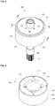
- FIG. 3 is a perspective view of a rotor assembly according to one embodiment of the present invention
- FIG. 4 is a perspective view of a ring magnet according to one embodiment of the present invention.
- DCT dual-clutch transmission
- a motor according to an embodiment of the present invention includes a housing 100, a stator part 300, and a rotor assembly 200 disposed in the stator part 300.
- the housing 100 has one open side so that the stator part 300 may be disposed and fixed in the housing 100.
- a shape of the housing 100 may be formed to vary depending on a type of motor to be used.
- a pair of motors may be disposed in the housing 100 with a shape shown in FIG. 1 .
- a power output shaft (not shown) may be disposed on one side of the housing 100.
- the power output shaft may selectively receive power from a shaft 230 of the rotor assembly 200.
- the DCT includes a set of two clutches so that first, third, and fifth-shift stages (a first speed change) are performed with power transmitted through one clutch, and second, forth, and sixth-shift stages (a second speed change) are performed with power transmitted through the other clutch.
- first, third, and fifth-shift stages a first speed change
- second, forth, and sixth-shift stages a second speed change
- one motor of the pair of motors may transmit power for the first speed change
- the other motor may transmit power for the second speed change.
- the DCT may provide convenient driving and smooth speed change like a vehicle with a conventional automatic transmission, and may provide fuel efficiency higher than that of a vehicle with a conventional manual transmission.
- the DCT includes a dual clutch 2 including a set of two clutches, a transmission control unit 3 configured to set each transmission by receiving power from the dual clutch 2, a clutch actuator 1 configured to control each of the clutches of the dual clutch 2, a gear shifting actuator 4 configured to shift gears by performing selecting and shifting on the transmission control unit 3, and a control unit 5 configured to control the clutch actuator 1 and the gear shifting actuator 4 by receiving all information of a vehicle, such as a vehicle speed, and a gear shifting command.
- a vehicle such as a vehicle speed, and a gear shifting command.
- the DCT is connected to the motor by a selecting operation of the clutch actuator 1 and transmits power to each transmission.
- a structure of the DCT is not necessarily limited thereto, and various well-known configurations that control gear shifting by receiving driving power from the motor may be applied thereto.
- the stator part 300 is disposed in the housing 100.
- an insulator is disposed in a stator core, and a coil may be wound around the insulator. Therefore, the stator core is electrically insulated even when power is applied to the coil. Therefore, the stator core may include a coil wound around an integral stator core, and may be formed by coupling a plurality of divided cores to each other.
- the rotor assembly 200 includes the shaft 230, a ring magnet 210, and a core member 220 that fixes the shaft 230 and the ring magnet 210.
- a plurality of second grooves 224 and a plurality of third grooves 225 may be formed on an upper surface of the core member 220.
- the second grooves 224 may have a shape corresponding to a shape of a nozzle injecting a molten injected resin into a metal mold when an injection molding of the core member is performed.
- the second grooves 224 may be formed at appropriate positions at which a flow of the resin is easily controlled when the injection molding is performed.
- a plurality of third grooves 225 may be formed on an upper surface of the core member 220.
- the third grooves 225 may be formed at positions corresponding to positions of first grooves formed on the ring magnet 210. Therefore, the third grooves 225 may be a standard for controlling a mounting position when the rotor assembly 200 is mounted in the motor.
- the number of third grooves 225 may be the same as the number of first grooves of the ring magnet 210.
- the shaft 230 is disposed to pass through the core member 220 and the ring magnet 210, and a gear 231 that transmits power to a transmission may be formed at one end of the shaft 230.
- the ring magnet 210 has one surface 212 and the other surface 213, and an insertion hole 211 into which the shaft 230 is inserted and which is formed at the center of the ring magnet 210.
- the ring magnet 210 may be manufactured with a ferrite sintering method.
- the ring magnet 210 is a ferromagnetic oxide containing an iron oxide as a main component, and thus the ring magnet 210 is very chemically stable and may be a polar anisotropic ferrite sintered magnet using a Sr or Ba-based ferrite magnetization direction.
- a method of manufacturing the ring magnet 210 includes a first step of wet-mixing iron oxide with a Sr or Ba-based oxide or carbide, a second step of performing calcination and crushing with a ferrite chemical reaction process, and a third step of adding a sintering additive, such as CaCO3, SiO2, SrCO3, to the crushed material and forming a fine-milled slurry with an average grain diameter of .75-1.0 ⁇ m using a ball mill.
- a sintering additive such as CaCO3, SiO2, SrCO3
- the method of manufacturing the ring magnet 210 further includes a fourth step of molding a multi-polar anisotropic magnet or a radial anisotropic magnet by drying the slurry and sintering and processing the formed object.
- First grooves 215 may be a standard for deciding a magnetism direction of the ring magnet 210.
- the number of the first grooves 215 may be appropriately controlled depending on a pole number of magnet.
- a plurality of first grooves 215 may be formed to surround the insertion hole 211 and may be connected to the insertion hole 211.
- the insertion hole 211 is connected to an inclined surface 214 and may be formed to be wider toward the outside.
- the first grooves 215 may be formed to be wider in an axial direction.
- FIG. 4 illustrates a configuration in which the ring magnet 210 is magnetized to have eight poles.
- the ring magnet 210 may be oriented in a dotted arrow direction as a magnetization direction thereof.
- the ring magnet 210 is not limited thereto, and may have a configuration in which the ring magnet is oriented in a radial direction as the magnetization direction thereof.
- FIG. 5 is a cross-sectional view of FIG. 3 taken in a direction of A-A
- FIG. 6 is a cross-sectional view of FIG. 3 taken in a direction of B-B.
- the core member 220 includes a body portion 221 formed between the ring magnet 210 and the shaft 230 to fix the ring magnet 210 and the shaft 230, and extension portions 222 and 223 that extend from the body portion 221 and cover an upper surface and a lower surface of the ring magnet 210.
- the core member 220 is formed between the ring magnet 210 and the shaft 230 by injection molding so that a manufacturing process thereof is simple. A weight of the rotor assembly 200 is reduced and an impact caused by vibration is mitigated.
- the core member may be manufactured of polyphenylene sulfide (PPS) or polyamide 9T (PA9T) which have a good thermal stability.
- PPS polyphenylene sulfide
- PA9T polyamide 9T
- the core member 220 is not limited thereto, and the core member 220 may be manufactured of various injected polymer resins.
- the extension portions 222 and 223 include a first extension portion 222 covering the upper surface of the ring magnet 210 and a second extension portion 223 covering the lower surface of the ring magnet 210.
- the first extension portion 222 and the second extension portion 223 may be formed in a disk shape and may have practically the same diameter and thickness.
- the extension portions 222 and 223 have a predetermined thickness. Therefore, a length H2 of the core member 220 in an axial direction is greater than a length H1 of the ring magnet 210.
- the extension portions 222 and 223 may have a thickness that is sufficient to protect the upper surface and the lower surface of the ring magnet 210. Therefore, an exposed area of the ring magnet 210 is reduced and generation of a crack is reduced.
- the first extension portion 222 includes the plurality of second grooves 224.
- the second grooves 224 may include protrusion portions 224a protruding from a bottom surface thereof.
- the protrusion portions 224a may be formed to be lower than a flat surface (an upper surface) of the first extension portion 222.
- Shapes of the second grooves 224 may correspond to a shape of a nozzle injecting a molten resin into a metal mold when the core member 220 is injection molded.
- the second grooves 224 may be formed at appropriate positions to easily control a flow of the injected resin.
- the ring magnet 210 may have a specific gravity of 7.4 to 7.8, and a specific gravity of the core member 220 configured of an injected resin may be 1.5 to 1.9.
- the first extension portion 222 may include a fixing part 222a coupled to the first groove 215 formed on the ring magnet 210.
- the fixing part 222a may be a portion inserted into the first groove 215 when the injection molding is performed. Therefore, the ring magnet 210 and the core member 220 may be prevented from slipping even when the rotor assembly 200 rotates at a high speed.
- the first extension portion 222 may include the third grooves 225 that correspond to the first grooves 215. Also, the second extension portion 223 may include fourth grooves 225a that correspond to the third grooves 225.
- the shaft 230 may include a fixing groove 232 formed on an inner circumferential surface thereof.
- the fixing groove 232 is intermittently or continuously formed to increase bonding force between the core member 220 and the shaft 230.
- the gear 231 that transmits power is formed at one end of the shaft 230, and a groove 233 to which a magnet (400 of FIG. 1 ) may be attached may be formed at the other end thereof.
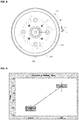
- FIG. 7 is a planar projection view of the rotor assembly according to one embodiment of the present invention
- FIG. 8 is a modified example of FIG. 7 .
- the third grooves 225 may be formed at positions corresponding to the first grooves 215 of the ring magnet 210 when seen in the planar projection view. Therefore, a third imaginary straight line (overlapped with L1) passing through the center of a first imaginary circle C1 and the third grooves 225 may correspond to a first imaginary straight line L1 passing through the center of the first imaginary circle C1 and the first grooves 215.
- the third grooves 225 are formed at positions corresponding to the first grooves 215 which are a standard for setting the magnetization direction of the ring magnet, and the rotor assembly may be accurately mounted on the motor using the third grooves 225.
- the plurality of first grooves 215 of the ring magnet 210 are disposed along the first imaginary circle C1, and the plurality of second grooves 224 may be disposed along a second imaginary circle C2.
- the first imaginary circle C1 may have the same diameter as that of the insertion hole of the ring magnet and a diameter greater than that of the insertion hole.
- a diameter of the second imaginary circle C2 may be smaller than the diameter of the first imaginary circle C1.
- a pressure of the injected resin introduced when the injection molding is performed is directly applied to one surface of the ring magnet 210, and thus the ring magnet 210 may be damaged.
- the diameter of the first extension portion 222 of the core member is formed to be greater than the first imaginary circle C1 to cover the one surface and the other surface of the ring magnet 210.
- the first extension portion 222 may cover the first groove 215 of the ring magnet 210.
- a ratio of a diameter of the body portion of the core member to the diameter of the ring magnet may be 1:2 to 1:2.5.
- a diameter D1 of the first imaginary circle C1, a diameter D2 of the second imaginary circle C2, a diameter D3 of the first extension portion 222, and a diameter D4 of the ring magnet 210 may satisfy the following formula 1.
- the second grooves 224 may be disposed not to be on the first imaginary straight line L1 passing through the center of the first imaginary circle C1 and the plurality of first grooves 215.
- an injection pressure is directly applied to the the first grooves 215 when the core member 220 is injection-molded, and thus there is a problem in which excessive stress is concentrated on the first grooves 215.
- a temperature of the injected resin is greater than or equal to about 300°C so that a momentary temperature difference is generated and a thermal impact may cause cracks around the first grooves 215.
- the second grooves 224 are disposed not to be on the first imaginary straight lines L1, and thus a stress applied to the first grooves 215 may be relatively mitigated when the rotor is manufactured.
- Each of the first grooves 215 and/or the third grooves 225 may be disposed between a plurality of second grooves 224a, 224b and 224c, and the first grooves 215 and the second grooves 224 may be disposed at an angle of about 25° to 55°.
- an angle ⁇ 11 between the second groove 224b and the third groove 225 may be the same as or different from an angle ⁇ 12 between the second groove 224c and the third groove 225.
- the third grooves 225 and the first grooves 215 may be disposed not to correspond to each other.
- Such a structure has an advantage in that the core member 220 may stably support the ring magnet 210 when the rotor rotates at high speed by increasing the thicknesses of the extension portions 222 and 223 filling the first grooves 215.
- the first imaginary straight line L1 and each of a third imaginary straight line L3 passing through the center of the first imaginary circle C1 and the third grooves 225 are disposed not to correspond to each other so that a predetermined angle ⁇ 3 exists between them.
- the third imaginary straight line L3 and the first imaginary straight line L1 may have an angle of less than or equal to 10°.
- the second grooves 224 may be disposed at positions which also do not correspond to the third imaginary straight lines L3. That is, the angle ⁇ 3 between the third imaginary straight line L3 and the first imaginary straight line L1 may be less than an angle ⁇ 2 between the second imaginary straight line L2 and the first imaginary straight line L1. That is, the third grooves 225 may be disposed closer to the first grooves 215 than the second grooves 224.
- the third grooves 225 may mark the magnetization direction of the ring magnet, and thus it is advantageous to dispose the third grooves 225 close to the first grooves 215.
- the second grooves 224 are disposed as far away from the first grooves 215 as possible to mitigate stress applied to the first grooves 215.
- FIG. 9 is a graph of measured slip torque of the motor according to one embodiment of the present invention
- FIG. 10 is a graph of measured coating effects according to one embodiment of the present invention.
- the vertical axis shows a torque value (N.mm).
- the left side (Before) of the horizontal axis shows torque data of an existing motor, and the right side (After) thereof shows torque data of a motor using the rotor according to the embodiment of the present invention.
- the motor according to the embodiment of the present invention generates 40 N.m of torque, while the existing motor generates 25 N.m of torque.
- the torque data of the motor to which the embodiment of the present invention is applied is more remarkably increased compared to the torque of the existing motor.
- the first grooves of the ring magnet are filled with the core member so that the extension portions of the core member cover the upper surface and the lower surface of the ring magnet, and thus slip torque is increased.
- Slip torque refers to torque generated when a magnet slips from a core member when a rotor suddenly stops during rotation.
- a coating layer may be formed on at least one of the one surface 212, the other surface 213, and an outer circumferential surface 216 of the ring magnet 210. Therefore, even through cracks are generated on the ring magnet 210, a cracked material is prevented from being discharged to the outside, and thus the performance of the motor can be increased. Also, the magnet is prevented from being corroded.
- a method of forming a coating layer includes sanding and preheating a surface of the ring magnet 210, coating the sanded surface, post-heating the coating layer, and manufacturing the coating layer.
- the coating method is only an exemplary example and is not limited thereto. Various coating methods may be applied depending on kinds of coating materials.
- a Teflon coating layer may be formed at a thickness of 10 to 30 ⁇ m.
- the coating material is not necessarily limited thereto, and various coating materials that prevent a crack generated in the ring magnet 210 or corrosion of the magnet may be selected.
- the vertical axis in FIG. 10 shows an inner pressure value of the ring magnet 210.
- the left side of the horizontal axis shows inner pressure data when a Teflon coating is not formed, and the right side thereof shows an inner pressure data when a 20 ⁇ m thickness Teflon coating is formed.
- inner pressure performance is increased more than the case in which the coating is not formed.
Landscapes
- Engineering & Computer Science (AREA)
- Power Engineering (AREA)
- General Engineering & Computer Science (AREA)
- Mechanical Engineering (AREA)
- Permanent Field Magnets Of Synchronous Machinery (AREA)
- Friction Gearing (AREA)
- Iron Core Of Rotating Electric Machines (AREA)
Abstract
Description
- The present invention relates to a rotor assembly, a motor, and a dual-clutch transmission (DCT) including the same.
- A transmission of a vehicle, which is a transmission device manually operated by a clutch operation of a user or automatically operated by a mission depending on speed, is configured to include a motor.
- Generally, an interior permanent magnet (IPM)-type motor having a permanent magnet installed in a rotor is used as a motor of a transmission.
- Since an IPM-type motor uses an NdFeB-based permanent magnet which is lightweight and has strong magnetism, it has an advantage of high efficiency and power density.
- However, an NdFeB-based permanent magnet includes neodymium (Nd), which is a rare earth, and thus there is a problem of an increase in manufacturing costs of a motor itself due to an increase in price of the rare earth.
- Therefore, the recent trend is toward a rare earth-free motor which does not use rare earths.
- A rare earth-free motor includes a ferrite magnet motor, an induction motor, a reluctance motor, and so on, and the most representative motor of these is the ferrite magnet motor.
- A ferrite magnet motor is a motor using a ferrite magnet, which is a magnetic ceramic, and has an advantage of lower price and easier design than a rare earth motor.
- However, since a ferrite magnet is relatively vulnerable to impact, it has problems in that a crack is generated when a motor rotates at a high speed and the performance of the motor is degraded due to discharging a cracked material.
- The present invention is directed to providing a motor which is able to suppress a crack generated in a magnet.
- One aspect of the present invention provides a motor including a stator part and a rotor assembly disposed to be rotatable with the stator part. The rotor assembly may include a ring magnet configured to include an insertion hole in which a shaft is disposed and a plurality of first grooves formed on one surface thereof along a first imaginary circle and a core member configured to include a body portion disposed between the shaft and the insertion hole and an extension portion covering the plurality of first grooves. The extension portion may include a plurality of second grooves which are not on a plurality of first imaginary straight lines that respectively pass from a center of the first imaginary circle through the plurality of first grooves.
- The plurality of second grooves may be disposed along a second imaginary circle defined on the extension portion.
- A diameter of the second imaginary circle may be less than a diameter of the first imaginary circle.
- The extension portion may have a diameter greater than a diameter of the first imaginary circle and cover at least a part of one surface and the other surface of the ring magnet.
- The diameter of the first imaginary circle, the diameter of the second imaginary circle, a diameter of the extension portion, and a diameter of the ring magnet may satisfy the following
formula 1.
- Herein, D1 is the diameter of the first imaginary circle, D2 is the diameter of the second imaginary circle, D3 is the diameter of the extension portion, and D4 is the diameter of the ring magnet.
- An axial length of the core member may be greater than a length of the ring magnet.
- The extension portion may include a plurality of third grooves formed on one surface thereof.
- The number of the third grooves may be the same as the number of the first grooves.
- Third imaginary straight lines respectively passing from the center of the first imaginary circle through the third grooves may overlap with the first imaginary straight lines.
- The third imaginary straight lines respectively passing from the center of the first imaginary circle through the third grooves may respectively have a predetermined angle with the first imaginary straight lines.
- The second grooves are respectively disposed not to be on the third imaginary straight lines respectively passing from the center of the first imaginary circle through the third grooves.
- An angle between each of the third imaginary straight lines respectively passing from the center of the first imaginary circle through the third grooves and each of the first straight lines may be less than an angle between each of second imaginary straight lines respectively passing from the center of the first imaginary circle through the second grooves and each of the first imaginary straight lines.
- The angle between each of the third imaginary straight lines and each of the first imaginary straight lines is less than or equal to 10°.
- The extension portion may include a first extension portion extending toward the one surface of the ring magnet and a second extension portion extending toward the other surface of the ring magnet, and the first extension portion and the second extension portion may be formed in a disk shape and have practically the same diameter.
- The second grooves may have protrusion portions protruding from a bottom surface thereof.
- Ends of the protrusion portions may be formed to be lower than a flat surface of the extension portion.
- Another aspect of the present invention provides a motor including a stator part and a rotor assembly disposed to be rotatable with the stator part. The rotor assembly may include a ring magnet including an insertion hole in which a shaft is disposed, and a core member disposed between the shaft and the insertion hole and extending toward one surface and the other surface of the ring magnet. An extension portion may include a plurality of second and third grooves. The extension portion may include a plurality of second grooves which are not on a plurality of third imaginary straight lines respectively passing from a center of the insertion hole through the plurality of third grooves.
- A rotor assembly according to an exemplary embodiment of the present invention reduces generation of a crack by minimizing a pressure applied to a ring magnet when the rotor assembly is manufactured.
- Also, the rotor assembly can use an injected resin instead of a metal core to reduce a weight of the rotor and mitigate an impact caused by vibration.
- The rotor assembly, a motor and a dual-clutch transmission (DCT) including the same reduce an exposed area of the ring magnet and reduce generation of a crack.
- The rotor assembly increases performance of the motor by preventing a cracked material from being discharged to the outside even when a crack is generated on the ring magnet.
- The various effects and advantages of the present invention are not limited to the above description and may be more easily understood through a process of describing a detailed description of the exemplary embodiment of the present invention.
-
-
FIG. 1 is a conceptual view of a motor according to one embodiment of the present invention; -
FIG. 2 is a conceptual view of a dual-clutch transmission (DCT) that the motor of one embodiment of the present invention is applied to; -
FIG. 3 is a perspective view of a rotor assembly according to one embodiment of the present invention; -
FIG. 4 is a perspective view of a ring magnet according to one embodiment of the present invention; -
FIG. 5 is a cross-sectional view ofFIG. 3 taken in a direction of A-A; -
FIG. 6 is a cross-sectional view ofFIG.3 taken in a direction of B-B; -
FIG. 7 is a planar projection view of the rotor assembly according to one embodiment of the present invention; -
FIG. 8 is a modified example ofFIG. 7 ; -
FIG. 9 is a graph of measured slip torque of the motor according to one embodiment of the present invention; and -
FIG. 10 is a graph of measured coating effects according to one embodiment of the present invention. - While the present invention may be modified in various ways and take on various alternative forms, specific embodiments thereof are shown in the drawings and described in detail below as examples. There is no intention to limit the present invention to the particular forms disclosed, and the invention should cover all modifications, equivalents, and alternatives falling within the spirit and scope of the appended claims.
- It should be understood that, although the terms "first," "second," etc. may be used herein to describe various elements, these elements are not limited by these terms. These terms are only used to distinguish one element from another. For example, a second element could be termed a first element, and, similarly, a first element could be termed a second element, without departing from the scope of the present invention. As used herein, the term "and/or" includes any and all combinations of one or more of the associated listed items.
- It should be understood that when an element is referred to as being "connected" or "coupled" to another element, it may be directly connected or coupled to the other element or intervening elements may be present. In contrast, when an element is referred to as being "directly connected" or "directly coupled" to another element, there are no intervening elements present. Other words used to describe the relationship between elements should be interpreted in a like fashion (i.e., "between" versus "directly between," "adjacent" versus "directly adjacent," etc.).
- The terminology used herein is for the purpose of describing particular embodiments only and is not intended to be limiting to the invention. As used herein, the singular forms are intended to include the plural forms as well unless clearly indicated otherwise by context. It should be further understood that the terms "comprises," "comprising," "includes," and/or "including" specify the presence of stated features, integers, steps, operations, elements, and/or components when used herein, but do not preclude the presence or addition of one or more other features, integers, steps, operations, elements, components, and/or groups thereof.
- Unless otherwise defined, all terms (including technical and scientific terms) used herein have the same meaning as commonly understood by one of ordinary skill in the art to which this invention belongs. It should be further understood that terms, such as those defined in commonly used dictionaries, should be interpreted as having a meaning that is consistent with their meaning in the context of the relevant art and are not to be interpreted in an idealized or overly formal sense unless expressly so defined here.
- In the description of the embodiments according to the present invention, in a case in which any one element is formed "on" ("above") or "under" ("below") another element, "on" ("above") or "under" ("below") includes a case in which both of the elements are directly in contact with each other or at least one other element is indirectly disposed and formed between the two elements. Also, a case in which "on" ("above") or "under" ("below") is used may include a meaning of both an upward direction and a downward direction with respect to one element.
- Hereinafter, embodiments of the present invention will be described with reference to the accompanying drawings, but like reference numerals refer to like components and overlapping descriptions thereof will be omitted.
-
FIG. 1 is a concept view of a motor according to one embodiment of the present invention,FIG. 2 is a concept view of a dual-clutch transmission (DCT) that the motor of one embodiment of the present invention is applied to,FIG. 3 is a perspective view of a rotor assembly according to one embodiment of the present invention, andFIG. 4 is a perspective view of a ring magnet according to one embodiment of the present invention. - According to
FIG. 1 , a motor according to an embodiment of the present invention includes ahousing 100, astator part 300, and arotor assembly 200 disposed in thestator part 300. - The
housing 100 has one open side so that thestator part 300 may be disposed and fixed in thehousing 100. A shape of thehousing 100 may be formed to vary depending on a type of motor to be used. When thehousing 100 is used for a DCT, a pair of motors may be disposed in thehousing 100 with a shape shown inFIG. 1 . - A power output shaft (not shown) may be disposed on one side of the
housing 100. The power output shaft may selectively receive power from ashaft 230 of therotor assembly 200. - Unlike a single plate clutch transmission mounted in a conventional vehicle with a manual transmission, the DCT includes a set of two clutches so that first, third, and fifth-shift stages (a first speed change) are performed with power transmitted through one clutch, and second, forth, and sixth-shift stages (a second speed change) are performed with power transmitted through the other clutch. In this case, one motor of the pair of motors may transmit power for the first speed change, and the other motor may transmit power for the second speed change.
- The DCT may provide convenient driving and smooth speed change like a vehicle with a conventional automatic transmission, and may provide fuel efficiency higher than that of a vehicle with a conventional manual transmission.
- Referring to
FIG. 2 , the DCT includes adual clutch 2 including a set of two clutches, atransmission control unit 3 configured to set each transmission by receiving power from thedual clutch 2, aclutch actuator 1 configured to control each of the clutches of thedual clutch 2, a gear shifting actuator 4 configured to shift gears by performing selecting and shifting on thetransmission control unit 3, and acontrol unit 5 configured to control theclutch actuator 1 and the gear shifting actuator 4 by receiving all information of a vehicle, such as a vehicle speed, and a gear shifting command. - Therefore, the DCT is connected to the motor by a selecting operation of the
clutch actuator 1 and transmits power to each transmission. - However, a structure of the DCT is not necessarily limited thereto, and various well-known configurations that control gear shifting by receiving driving power from the motor may be applied thereto.
- Referring to
FIG. 1 again, thestator part 300 is disposed in thehousing 100. In thestator part 300, an insulator is disposed in a stator core, and a coil may be wound around the insulator. Therefore, the stator core is electrically insulated even when power is applied to the coil. Therefore, the stator core may include a coil wound around an integral stator core, and may be formed by coupling a plurality of divided cores to each other. - The
rotor assembly 200 includes theshaft 230, aring magnet 210, and acore member 220 that fixes theshaft 230 and thering magnet 210. - Referring to
FIG. 3 , a plurality ofsecond grooves 224 and a plurality ofthird grooves 225 may be formed on an upper surface of thecore member 220. Thesecond grooves 224 may have a shape corresponding to a shape of a nozzle injecting a molten injected resin into a metal mold when an injection molding of the core member is performed. Thesecond grooves 224 may be formed at appropriate positions at which a flow of the resin is easily controlled when the injection molding is performed. - A plurality of
third grooves 225 may be formed on an upper surface of thecore member 220. Thethird grooves 225 may be formed at positions corresponding to positions of first grooves formed on thering magnet 210. Therefore, thethird grooves 225 may be a standard for controlling a mounting position when therotor assembly 200 is mounted in the motor. The number ofthird grooves 225 may be the same as the number of first grooves of thering magnet 210. - The
shaft 230 is disposed to pass through thecore member 220 and thering magnet 210, and agear 231 that transmits power to a transmission may be formed at one end of theshaft 230. - Referring to
FIG. 4 , thering magnet 210 has onesurface 212 and theother surface 213, and aninsertion hole 211 into which theshaft 230 is inserted and which is formed at the center of thering magnet 210. Thering magnet 210 may be manufactured with a ferrite sintering method. - The
ring magnet 210 is a ferromagnetic oxide containing an iron oxide as a main component, and thus thering magnet 210 is very chemically stable and may be a polar anisotropic ferrite sintered magnet using a Sr or Ba-based ferrite magnetization direction. - A method of manufacturing the
ring magnet 210 includes a first step of wet-mixing iron oxide with a Sr or Ba-based oxide or carbide, a second step of performing calcination and crushing with a ferrite chemical reaction process, and a third step of adding a sintering additive, such as CaCO3, SiO2, SrCO3, to the crushed material and forming a fine-milled slurry with an average grain diameter of .75-1.0 µm using a ball mill. - The method of manufacturing the
ring magnet 210 further includes a fourth step of molding a multi-polar anisotropic magnet or a radial anisotropic magnet by drying the slurry and sintering and processing the formed object. -
First grooves 215 may be a standard for deciding a magnetism direction of thering magnet 210. The number of thefirst grooves 215 may be appropriately controlled depending on a pole number of magnet. A plurality offirst grooves 215 may be formed to surround theinsertion hole 211 and may be connected to theinsertion hole 211. Theinsertion hole 211 is connected to aninclined surface 214 and may be formed to be wider toward the outside. Thefirst grooves 215 may be formed to be wider in an axial direction. -
FIG. 4 illustrates a configuration in which thering magnet 210 is magnetized to have eight poles. Thering magnet 210 may be oriented in a dotted arrow direction as a magnetization direction thereof. However, thering magnet 210 is not limited thereto, and may have a configuration in which the ring magnet is oriented in a radial direction as the magnetization direction thereof. -
FIG. 5 is a cross-sectional view ofFIG. 3 taken in a direction of A-A, andFIG. 6 is a cross-sectional view ofFIG. 3 taken in a direction of B-B. - Referring to
FIG. 5 , thecore member 220 includes abody portion 221 formed between thering magnet 210 and theshaft 230 to fix thering magnet 210 and theshaft 230, andextension portions body portion 221 and cover an upper surface and a lower surface of thering magnet 210. - The
core member 220 is formed between thering magnet 210 and theshaft 230 by injection molding so that a manufacturing process thereof is simple. A weight of therotor assembly 200 is reduced and an impact caused by vibration is mitigated. The core member may be manufactured of polyphenylene sulfide (PPS) or polyamide 9T (PA9T) which have a good thermal stability. However, thecore member 220 is not limited thereto, and thecore member 220 may be manufactured of various injected polymer resins. - Specifically, the
extension portions first extension portion 222 covering the upper surface of thering magnet 210 and asecond extension portion 223 covering the lower surface of thering magnet 210. Thefirst extension portion 222 and thesecond extension portion 223 may be formed in a disk shape and may have practically the same diameter and thickness. - The
extension portions core member 220 in an axial direction is greater than a length H1 of thering magnet 210. Theextension portions ring magnet 210. Therefore, an exposed area of thering magnet 210 is reduced and generation of a crack is reduced. - The
first extension portion 222 includes the plurality ofsecond grooves 224. Thesecond grooves 224 may includeprotrusion portions 224a protruding from a bottom surface thereof. Theprotrusion portions 224a may be formed to be lower than a flat surface (an upper surface) of thefirst extension portion 222. Shapes of thesecond grooves 224 may correspond to a shape of a nozzle injecting a molten resin into a metal mold when thecore member 220 is injection molded. Thesecond grooves 224 may be formed at appropriate positions to easily control a flow of the injected resin. - The
ring magnet 210 may have a specific gravity of 7.4 to 7.8, and a specific gravity of thecore member 220 configured of an injected resin may be 1.5 to 1.9. - Referring to
FIG. 6 , thefirst extension portion 222 may include a fixingpart 222a coupled to thefirst groove 215 formed on thering magnet 210. The fixingpart 222a may be a portion inserted into thefirst groove 215 when the injection molding is performed. Therefore, thering magnet 210 and thecore member 220 may be prevented from slipping even when therotor assembly 200 rotates at a high speed. - The
first extension portion 222 may include thethird grooves 225 that correspond to thefirst grooves 215. Also, thesecond extension portion 223 may includefourth grooves 225a that correspond to thethird grooves 225. - The
shaft 230 may include a fixinggroove 232 formed on an inner circumferential surface thereof. The fixinggroove 232 is intermittently or continuously formed to increase bonding force between thecore member 220 and theshaft 230. Thegear 231 that transmits power is formed at one end of theshaft 230, and agroove 233 to which a magnet (400 ofFIG. 1 ) may be attached may be formed at the other end thereof. -
FIG. 7 is a planar projection view of the rotor assembly according to one embodiment of the present invention, andFIG. 8 is a modified example ofFIG. 7 . - Referring to
FIG. 7 , thethird grooves 225 may be formed at positions corresponding to thefirst grooves 215 of thering magnet 210 when seen in the planar projection view. Therefore, a third imaginary straight line (overlapped with L1) passing through the center of a first imaginary circle C1 and thethird grooves 225 may correspond to a first imaginary straight line L1 passing through the center of the first imaginary circle C1 and thefirst grooves 215. - The
third grooves 225 are formed at positions corresponding to thefirst grooves 215 which are a standard for setting the magnetization direction of the ring magnet, and the rotor assembly may be accurately mounted on the motor using thethird grooves 225. - The plurality of
first grooves 215 of thering magnet 210 are disposed along the first imaginary circle C1, and the plurality ofsecond grooves 224 may be disposed along a second imaginary circle C2. In this case, the first imaginary circle C1 may have the same diameter as that of the insertion hole of the ring magnet and a diameter greater than that of the insertion hole. - A diameter of the second imaginary circle C2 may be smaller than the diameter of the first imaginary circle C1. When the second imaginary circle C2 is larger than the first imaginary circle C1, a pressure of the injected resin introduced when the injection molding is performed is directly applied to one surface of the
ring magnet 210, and thus thering magnet 210 may be damaged. - The diameter of the
first extension portion 222 of the core member is formed to be greater than the first imaginary circle C1 to cover the one surface and the other surface of thering magnet 210. In the case, thefirst extension portion 222 may cover thefirst groove 215 of thering magnet 210. Particularly, a ratio of a diameter of the body portion of the core member to the diameter of the ring magnet may be 1:2 to 1:2.5. - Therefore, a diameter D1 of the first imaginary circle C1, a diameter D2 of the second imaginary circle C2, a diameter D3 of the
first extension portion 222, and a diameter D4 of thering magnet 210 may satisfy the followingformula 1.
- The
second grooves 224 may be disposed not to be on the first imaginary straight line L1 passing through the center of the first imaginary circle C1 and the plurality offirst grooves 215. When thesecond grooves 224 are disposed on the first imaginary straight line L1, an injection pressure is directly applied to the thefirst grooves 215 when thecore member 220 is injection-molded, and thus there is a problem in which excessive stress is concentrated on thefirst grooves 215. - Also, a temperature of the injected resin is greater than or equal to about 300°C so that a momentary temperature difference is generated and a thermal impact may cause cracks around the
first grooves 215. - Therefore, the
second grooves 224 are disposed not to be on the first imaginary straight lines L1, and thus a stress applied to thefirst grooves 215 may be relatively mitigated when the rotor is manufactured. - Each of the
first grooves 215 and/or thethird grooves 225 may be disposed between a plurality ofsecond grooves first grooves 215 and thesecond grooves 224 may be disposed at an angle of about 25° to 55°. In this case, an angle θ11 between thesecond groove 224b and thethird groove 225 may be the same as or different from an angle θ12 between thesecond groove 224c and thethird groove 225. - Referring to
FIG. 8 , thethird grooves 225 and thefirst grooves 215 may be disposed not to correspond to each other. Such a structure has an advantage in that thecore member 220 may stably support thering magnet 210 when the rotor rotates at high speed by increasing the thicknesses of theextension portions first grooves 215. - Therefore, the first imaginary straight line L1 and each of a third imaginary straight line L3 passing through the center of the first imaginary circle C1 and the
third grooves 225 are disposed not to correspond to each other so that a predetermined angle θ3 exists between them. For example, the third imaginary straight line L3 and the first imaginary straight line L1 may have an angle of less than or equal to 10°. - In this case, the
second grooves 224 may be disposed at positions which also do not correspond to the third imaginary straight lines L3. That is, the angle θ3 between the third imaginary straight line L3 and the first imaginary straight line L1 may be less than an angle θ2 between the second imaginary straight line L2 and the first imaginary straight line L1. That is, thethird grooves 225 may be disposed closer to thefirst grooves 215 than thesecond grooves 224. - The
third grooves 225 may mark the magnetization direction of the ring magnet, and thus it is advantageous to dispose thethird grooves 225 close to thefirst grooves 215. Thesecond grooves 224 are disposed as far away from thefirst grooves 215 as possible to mitigate stress applied to thefirst grooves 215. -
FIG. 9 is a graph of measured slip torque of the motor according to one embodiment of the present invention, andFIG. 10 is a graph of measured coating effects according to one embodiment of the present invention. - In
FIG. 9 , the vertical axis shows a torque value (N.mm). The left side (Before) of the horizontal axis shows torque data of an existing motor, and the right side (After) thereof shows torque data of a motor using the rotor according to the embodiment of the present invention. - Referring to
FIG. 9 , the motor according to the embodiment of the present invention generates 40 N.m of torque, while the existing motor generates 25 N.m of torque. The torque data of the motor to which the embodiment of the present invention is applied is more remarkably increased compared to the torque of the existing motor. The first grooves of the ring magnet are filled with the core member so that the extension portions of the core member cover the upper surface and the lower surface of the ring magnet, and thus slip torque is increased. Slip torque refers to torque generated when a magnet slips from a core member when a rotor suddenly stops during rotation. - Referring to
FIG. 4 , a coating layer may be formed on at least one of the onesurface 212, theother surface 213, and an outercircumferential surface 216 of thering magnet 210. Therefore, even through cracks are generated on thering magnet 210, a cracked material is prevented from being discharged to the outside, and thus the performance of the motor can be increased. Also, the magnet is prevented from being corroded. - A method of forming a coating layer includes sanding and preheating a surface of the
ring magnet 210, coating the sanded surface, post-heating the coating layer, and manufacturing the coating layer. However, the coating method is only an exemplary example and is not limited thereto. Various coating methods may be applied depending on kinds of coating materials. - A Teflon coating layer may be formed at a thickness of 10 to 30 µm. However, the coating material is not necessarily limited thereto, and various coating materials that prevent a crack generated in the
ring magnet 210 or corrosion of the magnet may be selected. - The vertical axis in
FIG. 10 shows an inner pressure value of thering magnet 210. The left side of the horizontal axis shows inner pressure data when a Teflon coating is not formed, and the right side thereof shows an inner pressure data when a 20 µm thickness Teflon coating is formed. Referring toFIG. 10 , when the Teflon coating is formed, inner pressure performance is increased more than the case in which the coating is not formed.
Claims (20)
- A rotor assembly comprising:a ring magnet configured to include an insertion hole in which a shaft is disposed and a plurality of first grooves formed on one surface thereof along a first imaginary circle; anda core member configured to include a body portion disposed between the shaft and the insertion hole and an extension portion covering the plurality of first grooves,wherein the extension portion includes a plurality of second grooves which are not on a plurality of first imaginary straight lines that respectively pass from a center of the first imaginary circle through the plurality of first grooves.
- The rotor assembly of claim 1, wherein the plurality of second grooves are disposed along a second imaginary circle defined on the extension portion.
- The rotor assembly of claim 2, wherein a diameter of the second imaginary circle is less than a diameter of the first imaginary circle.
- The rotor assembly of claim 1, wherein the extension portion has a diameter greater than a diameter of the first imaginary circle and covers at least one portion of the one surface and the other surface of the ring magnet.
- The rotor assembly of claim 4, wherein the diameter of the first imaginary circle, a diameter of the second imaginary circle, a diameter of the extension portion, and a diameter of the ring magnet satisfy formula 1,

- The rotor assembly of claim 1, wherein an axial length of the core member is greater than a length of the ring magnet.
- The rotor assembly of claim 1, wherein the extension portion includes a plurality of third grooves formed on one surface thereof.
- The rotor assembly of claim 7, wherein the number of third grooves is the same as the number of first grooves.
- The rotor assembly of claim 7, wherein third imaginary straight lines respectively passing from the center of the first imaginary circle through the third grooves overlap with the first imaginary straight lines.
- The rotor assembly of claim 7, wherein third imaginary straight lines respectively passing from the center of the first imaginary circle through the third grooves respectively have a predetermined angle with the first imaginary straight lines.
- The rotor assembly of claim 7, wherein each of the second grooves are disposed not to be on the third imaginary lines respectively passing from the center of the first imaginary circle through the third grooves.
- The rotor assembly of claim 7, wherein an angle between each of third imaginary straight lines respectively passing from the center of the first imaginary circle through the third grooves and each of the first straight lines is less than an angle between each of second imaginary straight lines respectively passing from the center of the first imaginary circle through the second grooves and each of the first imaginary straight lines.
- The rotor assembly of claim 12, wherein the angle between each of the third imaginary straight lines and each of the first imaginary straight lines is less than or equal to 10°.
- The rotor assembly of claim 1, wherein the extension portion includes a first extension portion extending toward the one surface of the ring magnet and a second extension portion extending toward the other surface of the ring magnet,
wherein the first extension portion and the second extension portion are formed in a disk shape and have practically the same diameter. - The rotor assembly of claim 1, wherein the second grooves have protrusion portions protruding from a bottom surface thereof.
- A rotor assembly comprising:a ring magnet configured to include an insertion hole in which a shaft is disposed; anda core member disposed between the shaft and the insertion hole and extending toward one surface and the other surface of the ring magnet,wherein an extension portion includes a plurality of second grooves and third grooves, andthe extension portion includes a plurality of second grooves which are not on a plurality of third imaginary straight lines respectively passing from a center of the insertion hole through the plurality of third grooves.
- The rotor assembly of claim 16, wherein the plurality of second grooves are disposed along a second imaginary circle defined on the extension portion.
- The rotor assembly of claim 17, wherein a diameter of the second imaginary circle is less than a diameter of the insertion hole.
- A motor comprising:a housing;a stator part disposed in the housing; anda rotor assembly according to any one of claims 1 to 18.
- A dual clutch transmission comprising:a pair of motors according to claim 19.wherein a first motor transmits power for a first speed change, and a second motor transmits power for a second speed change.
Applications Claiming Priority (2)
| Application Number | Priority Date | Filing Date | Title |
|---|---|---|---|
| KR1020140072114A KR101703891B1 (en) | 2014-06-13 | 2014-06-13 | Motor and dual clutch transmission including the same |
| PCT/KR2015/005941 WO2015190869A1 (en) | 2014-06-13 | 2015-06-12 | Rotor assembly, motor and dual clutch transmission |
Publications (3)
| Publication Number | Publication Date |
|---|---|
| EP3157137A1 true EP3157137A1 (en) | 2017-04-19 |
| EP3157137A4 EP3157137A4 (en) | 2018-01-24 |
| EP3157137B1 EP3157137B1 (en) | 2024-05-01 |
Family
ID=54833870
Family Applications (1)
| Application Number | Title | Priority Date | Filing Date |
|---|---|---|---|
| EP15807274.4A Active EP3157137B1 (en) | 2014-06-13 | 2015-06-12 | Rotor assembly, motor and dual clutch transmission |
Country Status (5)
| Country | Link |
|---|---|
| US (2) | US10566860B2 (en) |
| EP (1) | EP3157137B1 (en) |
| KR (1) | KR101703891B1 (en) |
| CN (3) | CN110544998B (en) |
| WO (1) | WO2015190869A1 (en) |
Families Citing this family (5)
| Publication number | Priority date | Publication date | Assignee | Title |
|---|---|---|---|---|
| KR101703891B1 (en) * | 2014-06-13 | 2017-02-07 | 엘지이노텍 주식회사 | Motor and dual clutch transmission including the same |
| US11654766B2 (en) * | 2018-05-04 | 2023-05-23 | Schaeffler Technologies AG & Co. KG | Hybrid module including stamped rotor carrier |
| KR102651815B1 (en) * | 2018-08-23 | 2024-03-29 | 엘지이노텍 주식회사 | Apparatus for sensing |
| DE102019102366A1 (en) * | 2019-01-30 | 2020-07-30 | Ebm-Papst St. Georgen Gmbh & Co. Kg | Rotor of an electric motor and electric motor |
| CN110661346A (en) * | 2019-10-10 | 2020-01-07 | 珠海格力节能环保制冷技术研究中心有限公司 | Compressor and air conditioner |
Family Cites Families (48)
| Publication number | Priority date | Publication date | Assignee | Title |
|---|---|---|---|---|
| US4206379A (en) * | 1976-12-22 | 1980-06-03 | Citizen Watch Co., Ltd. | Permanent magnet rotor assembly for electro-mechanical transducer |
| JPH0164970U (en) * | 1987-10-20 | 1989-04-26 | ||
| GB2217924B (en) * | 1988-04-25 | 1992-10-07 | Matsushita Electric Works Ltd | Permanent magnet rotor |
| US5829120A (en) * | 1993-02-15 | 1998-11-03 | Fanuc, Ltd. | Method for manufacturing a rotor for synchronous motor |
| US5811904A (en) * | 1996-03-21 | 1998-09-22 | Hitachi, Ltd. | Permanent magnet dynamo electric machine |
| KR0133850Y1 (en) * | 1996-11-30 | 1999-05-15 | 대우전자 주식회사 | Rib structure of injection mold |
| US6084330A (en) * | 1998-03-13 | 2000-07-04 | Kollmorgen Corporation | Permanent magnet rotor and method of assembly |
| DE19846918A1 (en) * | 1998-10-12 | 2000-04-13 | Bosch Gmbh Robert | Pole wheel has thermoplastic holder part with joining material in one piece with hollow magnetic body, and openings in which joining material is injection molded |
| JP2000333429A (en) | 2000-01-01 | 2000-11-30 | Matsushita Seiko Co Ltd | Brushless motor and method of manufacturing the same |
| JP4552267B2 (en) * | 2000-04-14 | 2010-09-29 | パナソニック株式会社 | motor |
| JP2001327105A (en) * | 2000-05-17 | 2001-11-22 | Fujitsu General Ltd | Motor rotor and method of manufacturing the same |
| JP4113666B2 (en) * | 2000-09-20 | 2008-07-09 | 三菱電機株式会社 | Magnet generator |
| DE10152151A1 (en) * | 2001-10-25 | 2003-05-15 | Buhler Motor Gmbh | Permanent magnet rotor for electric motor has permanent magnet ring consisting of compressed, polymer-bound rare earth magnets mounted on plastic mounting produced by injection molding around ring |
| JP3671398B2 (en) * | 2002-05-16 | 2005-07-13 | 三菱電機株式会社 | Magnet generator |
| JP2004104928A (en) * | 2002-09-11 | 2004-04-02 | Kokusan Denki Co Ltd | Motor |
| JP4208683B2 (en) * | 2003-09-24 | 2009-01-14 | 三菱電機株式会社 | Motor rotor, motor and air conditioner |
| JP2006086319A (en) * | 2004-09-16 | 2006-03-30 | Mitsubishi Electric Corp | Ring-type sintered magnet |
| JP4246136B2 (en) * | 2004-10-21 | 2009-04-02 | 三菱電機株式会社 | Manufacturing method of electric motor rotor, electric motor rotor, electric motor, air conditioner, refrigerator, ventilation fan, and electric motor rotor resin mold |
| CN2831587Y (en) | 2005-09-22 | 2006-10-25 | 宋太华 | Turbine generator rotor |
| CN2854906Y (en) * | 2005-11-16 | 2007-01-03 | 南京雨沛电子有限公司 | High water-proof submersible pump rotor |
| CN101068092A (en) * | 2006-05-01 | 2007-11-07 | 日本电产三协株式会社 | Stepping motor |
| JP2007325488A (en) * | 2006-05-01 | 2007-12-13 | Nidec Sankyo Corp | Stepping motor |
| JP4068653B2 (en) * | 2006-05-31 | 2008-03-26 | 山洋電気株式会社 | Rotor for motor |
| CN101154849A (en) * | 2006-09-27 | 2008-04-02 | 日本电产芝浦株式会社 | Rator unit, method for manufacturing the rator unit, motor and pump having the same |
| CN201118294Y (en) * | 2007-11-20 | 2008-09-17 | 建凖电机工业股份有限公司 | Motor rotor |
| TW201014122A (en) * | 2008-09-16 | 2010-04-01 | Sunonwealth Electr Mach Ind Co | Rotor of a motor |
| JP5457787B2 (en) | 2009-10-20 | 2014-04-02 | 日本電産サンキョー株式会社 | Motor rotor and motor |
| JP5005064B2 (en) * | 2010-05-07 | 2012-08-22 | 三菱電機株式会社 | Electric motor rotor, electric motor, method of manufacturing electric motor rotor, and air conditioner |
| CN201869071U (en) * | 2010-10-21 | 2011-06-15 | 德昌电机(深圳)有限公司 | Permanent-magnet motor |
| DE102011110752A1 (en) * | 2010-08-20 | 2012-03-15 | Johnson Electric S.A. | Brushless motor |
| CN201893631U (en) * | 2010-12-22 | 2011-07-06 | 卧龙电气集团股份有限公司 | Electric erosion preventing rotor |
| JP5600610B2 (en) | 2011-01-18 | 2014-10-01 | 三菱電機株式会社 | Motor rotor, mold motor, air conditioner, and mold motor manufacturing method |
| US9509180B2 (en) * | 2011-01-26 | 2016-11-29 | Makita Corporation | Brushless motor for electric power tool |
| JP5615349B2 (en) * | 2011-04-05 | 2014-10-29 | 三菱重工業株式会社 | Renewable energy power generator and hydraulic pump mounting method |
| JP5464604B2 (en) * | 2011-09-20 | 2014-04-09 | シナノケンシ株式会社 | Motor rotor and manufacturing method thereof, inner rotor type brushless motor and manufacturing method thereof |
| US9246365B2 (en) * | 2012-01-23 | 2016-01-26 | Aisan Kogyo Kabushiki Kaisha | Regulation of permanent magnet motion in a brushless motor |
| JP6029597B2 (en) * | 2012-01-31 | 2016-11-24 | 三菱電機株式会社 | Pump, refrigeration cycle apparatus and pump manufacturing method |
| EP2662954B1 (en) | 2012-05-09 | 2022-06-29 | LG Innotek Co., Ltd. | Motor |
| JP5496255B2 (en) * | 2012-05-31 | 2014-05-21 | 三菱電機株式会社 | Method for manufacturing rotor of magnet type rotating electrical machine and manufacturing apparatus thereof |
| DE102013012569A1 (en) * | 2012-07-31 | 2014-02-06 | Asmo Co., Ltd. | ROTOR, ENGINE AND ROTOR MANUFACTURING PROCESS |
| CN103580317B (en) | 2012-08-10 | 2017-08-08 | 浙江三花制冷集团有限公司 | A kind of canned motor pump magneto |
| JP5935615B2 (en) * | 2012-09-14 | 2016-06-15 | 株式会社デンソー | Rotating electrical machine rotor |
| CN104619990B (en) * | 2012-10-05 | 2017-03-29 | 三菱电机株式会社 | Motor rotors, motors, pumps and refrigeration cycle devices |
| JP2014173585A (en) * | 2013-03-13 | 2014-09-22 | Hitachi Automotive Systems Ltd | Electric fluid pump |
| KR101836545B1 (en) * | 2013-05-13 | 2018-03-08 | 엘지이노텍 주식회사 | Motor |
| JP6026000B2 (en) * | 2013-10-18 | 2016-11-16 | 三菱電機株式会社 | Electric motor rotor, electric motor, and air conditioner |
| CN104953737B (en) * | 2014-03-26 | 2019-03-22 | 德昌电机(深圳)有限公司 | A kind of permanent magnetic brushless |
| KR101703891B1 (en) | 2014-06-13 | 2017-02-07 | 엘지이노텍 주식회사 | Motor and dual clutch transmission including the same |
-
2014
- 2014-06-13 KR KR1020140072114A patent/KR101703891B1/en active Active
-
2015
- 2015-06-12 US US15/318,219 patent/US10566860B2/en not_active Ceased
- 2015-06-12 CN CN201910767909.2A patent/CN110544998B/en active Active
- 2015-06-12 EP EP15807274.4A patent/EP3157137B1/en active Active
- 2015-06-12 CN CN201910767910.5A patent/CN110635593B/en active Active
- 2015-06-12 WO PCT/KR2015/005941 patent/WO2015190869A1/en not_active Ceased
- 2015-06-12 US US17/060,885 patent/USRE49924E1/en active Active
- 2015-06-12 CN CN201580031594.5A patent/CN106464037B/en active Active
Also Published As
| Publication number | Publication date |
|---|---|
| KR20150143088A (en) | 2015-12-23 |
| US20170133896A1 (en) | 2017-05-11 |
| US10566860B2 (en) | 2020-02-18 |
| CN106464037B (en) | 2019-09-17 |
| CN110544998A (en) | 2019-12-06 |
| KR101703891B1 (en) | 2017-02-07 |
| CN106464037A (en) | 2017-02-22 |
| EP3157137A4 (en) | 2018-01-24 |
| CN110544998B (en) | 2021-08-17 |
| USRE49924E1 (en) | 2024-04-16 |
| CN110635593A (en) | 2019-12-31 |
| CN110635593B (en) | 2021-10-08 |
| EP3157137B1 (en) | 2024-05-01 |
| WO2015190869A1 (en) | 2015-12-17 |
Similar Documents
| Publication | Publication Date | Title |
|---|---|---|
| EP3157137B1 (en) | Rotor assembly, motor and dual clutch transmission | |
| EP2662954B1 (en) | Motor | |
| US20050225190A1 (en) | Rotor for brushless motor and brushless motor | |
| JP4812787B2 (en) | Method of manufacturing rotor for pump motor, pump motor, pump and rotor for pump motor | |
| KR101836545B1 (en) | Motor | |
| EP2744077B1 (en) | Rotor of a motor | |
| JP2019213451A (en) | Bonded rotor shaft | |
| CN107787546A (en) | Synchronous reluctance motor assisted by permanent magnets | |
| US20150061446A1 (en) | Rotor of brushless motor | |
| JP2005151757A (en) | Method for manufacturing rotor and rotor | |
| KR101445163B1 (en) | Magnetic pump using bonded magnetic | |
| KR101837667B1 (en) | Rotor and motor including the same | |
| KR101787444B1 (en) | Rotor and motor including the same | |
| KR102175934B1 (en) | Rotor and motor including the same | |
| US11368062B2 (en) | Rotor structure and rotor structure manufacturing method | |
| KR101332130B1 (en) | Motor | |
| EP3468002B1 (en) | Ipm motor rotor, ipm motor, and method for manufacturing ipm motor rotor | |
| JP2009201286A (en) | Claw pole type motor and pump with the same | |
| KR102297686B1 (en) | Rotor and motor including the same | |
| CN121569425A (en) | Rotor device and motor having the same | |
| JP2009201285A (en) | Claw-pole type motor and pump equipped with the motor | |
| KR20140095036A (en) | Rotor of motor | |
| JP2009201287A (en) | Claw pole type motor and pump with the motor |
Legal Events
| Date | Code | Title | Description |
|---|---|---|---|
| STAA | Information on the status of an ep patent application or granted ep patent |
Free format text: STATUS: THE INTERNATIONAL PUBLICATION HAS BEEN MADE |
|
| PUAI | Public reference made under article 153(3) epc to a published international application that has entered the european phase |
Free format text: ORIGINAL CODE: 0009012 |
|
| STAA | Information on the status of an ep patent application or granted ep patent |
Free format text: STATUS: REQUEST FOR EXAMINATION WAS MADE |
|
| 17P | Request for examination filed |
Effective date: 20161213 |
|
| AK | Designated contracting states |
Kind code of ref document: A1 Designated state(s): AL AT BE BG CH CY CZ DE DK EE ES FI FR GB GR HR HU IE IS IT LI LT LU LV MC MK MT NL NO PL PT RO RS SE SI SK SM TR |
|
| AX | Request for extension of the european patent |
Extension state: BA ME |
|
| RAP1 | Party data changed (applicant data changed or rights of an application transferred) |
Owner name: LG INNOTEK CO., LTD. |
|
| DAV | Request for validation of the european patent (deleted) | ||
| DAX | Request for extension of the european patent (deleted) | ||
| A4 | Supplementary search report drawn up and despatched |
Effective date: 20180104 |
|
| RIC1 | Information provided on ipc code assigned before grant |
Ipc: H02K 1/22 20060101AFI20171221BHEP Ipc: F16H 3/091 20060101ALI20171221BHEP Ipc: F16H 3/00 20060101ALN20171221BHEP Ipc: H02K 1/27 20060101ALI20171221BHEP Ipc: H02K 1/06 20060101ALN20171221BHEP Ipc: H02K 1/30 20060101ALI20171221BHEP |
|
| STAA | Information on the status of an ep patent application or granted ep patent |
Free format text: STATUS: EXAMINATION IS IN PROGRESS |
|
| 17Q | First examination report despatched |
Effective date: 20201222 |
|
| REG | Reference to a national code |
Ref country code: DE Ref legal event code: R079 Free format text: PREVIOUS MAIN CLASS: H02K0001060000 Ipc: H02K0001220000 Ref document number: 602015088569 Country of ref document: DE |
|
| GRAP | Despatch of communication of intention to grant a patent |
Free format text: ORIGINAL CODE: EPIDOSNIGR1 |
|
| STAA | Information on the status of an ep patent application or granted ep patent |
Free format text: STATUS: GRANT OF PATENT IS INTENDED |
|
| RIC1 | Information provided on ipc code assigned before grant |
Ipc: H02K 1/06 20060101ALN20231114BHEP Ipc: F16H 3/00 20060101ALN20231114BHEP Ipc: H02K 1/2733 20220101ALI20231114BHEP Ipc: H02K 1/30 20060101ALI20231114BHEP Ipc: F16H 3/091 20060101ALI20231114BHEP Ipc: H02K 1/22 20060101AFI20231114BHEP |
|
| INTG | Intention to grant announced |
Effective date: 20231130 |
|
| GRAS | Grant fee paid |
Free format text: ORIGINAL CODE: EPIDOSNIGR3 |
|
| GRAA | (expected) grant |
Free format text: ORIGINAL CODE: 0009210 |
|
| STAA | Information on the status of an ep patent application or granted ep patent |
Free format text: STATUS: THE PATENT HAS BEEN GRANTED |
|
| AK | Designated contracting states |
Kind code of ref document: B1 Designated state(s): AL AT BE BG CH CY CZ DE DK EE ES FI FR GB GR HR HU IE IS IT LI LT LU LV MC MK MT NL NO PL PT RO RS SE SI SK SM TR |
|
| REG | Reference to a national code |
Ref country code: GB Ref legal event code: FG4D |
|
| REG | Reference to a national code |
Ref country code: CH Ref legal event code: EP |
|
| REG | Reference to a national code |
Ref country code: IE Ref legal event code: FG4D |
|
| REG | Reference to a national code |
Ref country code: DE Ref legal event code: R096 Ref document number: 602015088569 Country of ref document: DE |
|
| REG | Reference to a national code |
Ref country code: NL Ref legal event code: FP |
|
| REG | Reference to a national code |
Ref country code: LT Ref legal event code: MG9D |
|
| PG25 | Lapsed in a contracting state [announced via postgrant information from national office to epo] |
Ref country code: IS Free format text: LAPSE BECAUSE OF FAILURE TO SUBMIT A TRANSLATION OF THE DESCRIPTION OR TO PAY THE FEE WITHIN THE PRESCRIBED TIME-LIMIT Effective date: 20240901 |
|
| PG25 | Lapsed in a contracting state [announced via postgrant information from national office to epo] |
Ref country code: BG Free format text: LAPSE BECAUSE OF FAILURE TO SUBMIT A TRANSLATION OF THE DESCRIPTION OR TO PAY THE FEE WITHIN THE PRESCRIBED TIME-LIMIT Effective date: 20240501 |
|
| PG25 | Lapsed in a contracting state [announced via postgrant information from national office to epo] |
Ref country code: FI Free format text: LAPSE BECAUSE OF FAILURE TO SUBMIT A TRANSLATION OF THE DESCRIPTION OR TO PAY THE FEE WITHIN THE PRESCRIBED TIME-LIMIT Effective date: 20240501 Ref country code: HR Free format text: LAPSE BECAUSE OF FAILURE TO SUBMIT A TRANSLATION OF THE DESCRIPTION OR TO PAY THE FEE WITHIN THE PRESCRIBED TIME-LIMIT Effective date: 20240501 |
|
| PG25 | Lapsed in a contracting state [announced via postgrant information from national office to epo] |
Ref country code: GR Free format text: LAPSE BECAUSE OF FAILURE TO SUBMIT A TRANSLATION OF THE DESCRIPTION OR TO PAY THE FEE WITHIN THE PRESCRIBED TIME-LIMIT Effective date: 20240802 |
|
| PG25 | Lapsed in a contracting state [announced via postgrant information from national office to epo] |
Ref country code: PT Free format text: LAPSE BECAUSE OF FAILURE TO SUBMIT A TRANSLATION OF THE DESCRIPTION OR TO PAY THE FEE WITHIN THE PRESCRIBED TIME-LIMIT Effective date: 20240902 |
|
| REG | Reference to a national code |
Ref country code: AT Ref legal event code: MK05 Ref document number: 1683754 Country of ref document: AT Kind code of ref document: T Effective date: 20240501 |
|
| PG25 | Lapsed in a contracting state [announced via postgrant information from national office to epo] |
Ref country code: ES Free format text: LAPSE BECAUSE OF FAILURE TO SUBMIT A TRANSLATION OF THE DESCRIPTION OR TO PAY THE FEE WITHIN THE PRESCRIBED TIME-LIMIT Effective date: 20240501 |
|
| PG25 | Lapsed in a contracting state [announced via postgrant information from national office to epo] |
Ref country code: AT Free format text: LAPSE BECAUSE OF FAILURE TO SUBMIT A TRANSLATION OF THE DESCRIPTION OR TO PAY THE FEE WITHIN THE PRESCRIBED TIME-LIMIT Effective date: 20240501 |
|
| PG25 | Lapsed in a contracting state [announced via postgrant information from national office to epo] |
Ref country code: PL Free format text: LAPSE BECAUSE OF FAILURE TO SUBMIT A TRANSLATION OF THE DESCRIPTION OR TO PAY THE FEE WITHIN THE PRESCRIBED TIME-LIMIT Effective date: 20240501 |
|
| PG25 | Lapsed in a contracting state [announced via postgrant information from national office to epo] |
Ref country code: LV Free format text: LAPSE BECAUSE OF FAILURE TO SUBMIT A TRANSLATION OF THE DESCRIPTION OR TO PAY THE FEE WITHIN THE PRESCRIBED TIME-LIMIT Effective date: 20240501 |
|
| PG25 | Lapsed in a contracting state [announced via postgrant information from national office to epo] |
Ref country code: PT Free format text: LAPSE BECAUSE OF FAILURE TO SUBMIT A TRANSLATION OF THE DESCRIPTION OR TO PAY THE FEE WITHIN THE PRESCRIBED TIME-LIMIT Effective date: 20240902 Ref country code: PL Free format text: LAPSE BECAUSE OF FAILURE TO SUBMIT A TRANSLATION OF THE DESCRIPTION OR TO PAY THE FEE WITHIN THE PRESCRIBED TIME-LIMIT Effective date: 20240501 Ref country code: NO Free format text: LAPSE BECAUSE OF FAILURE TO SUBMIT A TRANSLATION OF THE DESCRIPTION OR TO PAY THE FEE WITHIN THE PRESCRIBED TIME-LIMIT Effective date: 20240801 Ref country code: LV Free format text: LAPSE BECAUSE OF FAILURE TO SUBMIT A TRANSLATION OF THE DESCRIPTION OR TO PAY THE FEE WITHIN THE PRESCRIBED TIME-LIMIT Effective date: 20240501 Ref country code: IS Free format text: LAPSE BECAUSE OF FAILURE TO SUBMIT A TRANSLATION OF THE DESCRIPTION OR TO PAY THE FEE WITHIN THE PRESCRIBED TIME-LIMIT Effective date: 20240901 Ref country code: HR Free format text: LAPSE BECAUSE OF FAILURE TO SUBMIT A TRANSLATION OF THE DESCRIPTION OR TO PAY THE FEE WITHIN THE PRESCRIBED TIME-LIMIT Effective date: 20240501 Ref country code: GR Free format text: LAPSE BECAUSE OF FAILURE TO SUBMIT A TRANSLATION OF THE DESCRIPTION OR TO PAY THE FEE WITHIN THE PRESCRIBED TIME-LIMIT Effective date: 20240802 Ref country code: FI Free format text: LAPSE BECAUSE OF FAILURE TO SUBMIT A TRANSLATION OF THE DESCRIPTION OR TO PAY THE FEE WITHIN THE PRESCRIBED TIME-LIMIT Effective date: 20240501 Ref country code: ES Free format text: LAPSE BECAUSE OF FAILURE TO SUBMIT A TRANSLATION OF THE DESCRIPTION OR TO PAY THE FEE WITHIN THE PRESCRIBED TIME-LIMIT Effective date: 20240501 Ref country code: BG Free format text: LAPSE BECAUSE OF FAILURE TO SUBMIT A TRANSLATION OF THE DESCRIPTION OR TO PAY THE FEE WITHIN THE PRESCRIBED TIME-LIMIT Effective date: 20240501 Ref country code: AT Free format text: LAPSE BECAUSE OF FAILURE TO SUBMIT A TRANSLATION OF THE DESCRIPTION OR TO PAY THE FEE WITHIN THE PRESCRIBED TIME-LIMIT Effective date: 20240501 Ref country code: RS Free format text: LAPSE BECAUSE OF FAILURE TO SUBMIT A TRANSLATION OF THE DESCRIPTION OR TO PAY THE FEE WITHIN THE PRESCRIBED TIME-LIMIT Effective date: 20240801 |
|
| PG25 | Lapsed in a contracting state [announced via postgrant information from national office to epo] |
Ref country code: DK Free format text: LAPSE BECAUSE OF FAILURE TO SUBMIT A TRANSLATION OF THE DESCRIPTION OR TO PAY THE FEE WITHIN THE PRESCRIBED TIME-LIMIT Effective date: 20240501 |
|
| PG25 | Lapsed in a contracting state [announced via postgrant information from national office to epo] |
Ref country code: EE Free format text: LAPSE BECAUSE OF FAILURE TO SUBMIT A TRANSLATION OF THE DESCRIPTION OR TO PAY THE FEE WITHIN THE PRESCRIBED TIME-LIMIT Effective date: 20240501 |
|
| PG25 | Lapsed in a contracting state [announced via postgrant information from national office to epo] |
Ref country code: CZ Free format text: LAPSE BECAUSE OF FAILURE TO SUBMIT A TRANSLATION OF THE DESCRIPTION OR TO PAY THE FEE WITHIN THE PRESCRIBED TIME-LIMIT Effective date: 20240501 |
|
| PG25 | Lapsed in a contracting state [announced via postgrant information from national office to epo] |
Ref country code: RO Free format text: LAPSE BECAUSE OF FAILURE TO SUBMIT A TRANSLATION OF THE DESCRIPTION OR TO PAY THE FEE WITHIN THE PRESCRIBED TIME-LIMIT Effective date: 20240501 Ref country code: SK Free format text: LAPSE BECAUSE OF FAILURE TO SUBMIT A TRANSLATION OF THE DESCRIPTION OR TO PAY THE FEE WITHIN THE PRESCRIBED TIME-LIMIT Effective date: 20240501 |
|
| PG25 | Lapsed in a contracting state [announced via postgrant information from national office to epo] |
Ref country code: SM Free format text: LAPSE BECAUSE OF FAILURE TO SUBMIT A TRANSLATION OF THE DESCRIPTION OR TO PAY THE FEE WITHIN THE PRESCRIBED TIME-LIMIT Effective date: 20240501 |
|
| PG25 | Lapsed in a contracting state [announced via postgrant information from national office to epo] |
Ref country code: SM Free format text: LAPSE BECAUSE OF FAILURE TO SUBMIT A TRANSLATION OF THE DESCRIPTION OR TO PAY THE FEE WITHIN THE PRESCRIBED TIME-LIMIT Effective date: 20240501 Ref country code: SK Free format text: LAPSE BECAUSE OF FAILURE TO SUBMIT A TRANSLATION OF THE DESCRIPTION OR TO PAY THE FEE WITHIN THE PRESCRIBED TIME-LIMIT Effective date: 20240501 Ref country code: RO Free format text: LAPSE BECAUSE OF FAILURE TO SUBMIT A TRANSLATION OF THE DESCRIPTION OR TO PAY THE FEE WITHIN THE PRESCRIBED TIME-LIMIT Effective date: 20240501 Ref country code: EE Free format text: LAPSE BECAUSE OF FAILURE TO SUBMIT A TRANSLATION OF THE DESCRIPTION OR TO PAY THE FEE WITHIN THE PRESCRIBED TIME-LIMIT Effective date: 20240501 Ref country code: DK Free format text: LAPSE BECAUSE OF FAILURE TO SUBMIT A TRANSLATION OF THE DESCRIPTION OR TO PAY THE FEE WITHIN THE PRESCRIBED TIME-LIMIT Effective date: 20240501 Ref country code: CZ Free format text: LAPSE BECAUSE OF FAILURE TO SUBMIT A TRANSLATION OF THE DESCRIPTION OR TO PAY THE FEE WITHIN THE PRESCRIBED TIME-LIMIT Effective date: 20240501 Ref country code: MC Free format text: LAPSE BECAUSE OF FAILURE TO SUBMIT A TRANSLATION OF THE DESCRIPTION OR TO PAY THE FEE WITHIN THE PRESCRIBED TIME-LIMIT Effective date: 20240501 |
|
| REG | Reference to a national code |
Ref country code: CH Ref legal event code: PL |
|
| REG | Reference to a national code |
Ref country code: DE Ref legal event code: R097 Ref document number: 602015088569 Country of ref document: DE |
|
| PG25 | Lapsed in a contracting state [announced via postgrant information from national office to epo] |
Ref country code: LU Free format text: LAPSE BECAUSE OF NON-PAYMENT OF DUE FEES Effective date: 20240612 |
|
| PLBE | No opposition filed within time limit |
Free format text: ORIGINAL CODE: 0009261 |
|
| STAA | Information on the status of an ep patent application or granted ep patent |
Free format text: STATUS: NO OPPOSITION FILED WITHIN TIME LIMIT |
|
| 26N | No opposition filed |
Effective date: 20250204 |
|
| PG25 | Lapsed in a contracting state [announced via postgrant information from national office to epo] |
Ref country code: IE Free format text: LAPSE BECAUSE OF NON-PAYMENT OF DUE FEES Effective date: 20240612 |
|
| GBPC | Gb: european patent ceased through non-payment of renewal fee |
Effective date: 20240801 |
|
| PG25 | Lapsed in a contracting state [announced via postgrant information from national office to epo] |
Ref country code: BE Free format text: LAPSE BECAUSE OF NON-PAYMENT OF DUE FEES Effective date: 20240630 Ref country code: SI Free format text: LAPSE BECAUSE OF FAILURE TO SUBMIT A TRANSLATION OF THE DESCRIPTION OR TO PAY THE FEE WITHIN THE PRESCRIBED TIME-LIMIT Effective date: 20240501 Ref country code: CH Free format text: LAPSE BECAUSE OF NON-PAYMENT OF DUE FEES Effective date: 20240630 |
|
| REG | Reference to a national code |
Ref country code: BE Ref legal event code: MM Effective date: 20240630 |
|
| PGFP | Annual fee paid to national office [announced via postgrant information from national office to epo] |
Ref country code: NL Payment date: 20250520 Year of fee payment: 11 |
|
| PGFP | Annual fee paid to national office [announced via postgrant information from national office to epo] |
Ref country code: DE Payment date: 20250520 Year of fee payment: 11 |
|
| PG25 | Lapsed in a contracting state [announced via postgrant information from national office to epo] |
Ref country code: GB Free format text: LAPSE BECAUSE OF NON-PAYMENT OF DUE FEES Effective date: 20240801 |
|
| PGFP | Annual fee paid to national office [announced via postgrant information from national office to epo] |
Ref country code: IT Payment date: 20250523 Year of fee payment: 11 |
|
| PGFP | Annual fee paid to national office [announced via postgrant information from national office to epo] |
Ref country code: FR Payment date: 20250521 Year of fee payment: 11 |
|
| PG25 | Lapsed in a contracting state [announced via postgrant information from national office to epo] |
Ref country code: SE Free format text: LAPSE BECAUSE OF FAILURE TO SUBMIT A TRANSLATION OF THE DESCRIPTION OR TO PAY THE FEE WITHIN THE PRESCRIBED TIME-LIMIT Effective date: 20240501 |
|
| PG25 | Lapsed in a contracting state [announced via postgrant information from national office to epo] |
Ref country code: CY Free format text: LAPSE BECAUSE OF FAILURE TO SUBMIT A TRANSLATION OF THE DESCRIPTION OR TO PAY THE FEE WITHIN THE PRESCRIBED TIME-LIMIT; INVALID AB INITIO Effective date: 20150612 |
|
| PG25 | Lapsed in a contracting state [announced via postgrant information from national office to epo] |
Ref country code: HU Free format text: LAPSE BECAUSE OF FAILURE TO SUBMIT A TRANSLATION OF THE DESCRIPTION OR TO PAY THE FEE WITHIN THE PRESCRIBED TIME-LIMIT; INVALID AB INITIO Effective date: 20150612 |