EP3157074A1 - Battery cell - Google Patents
Battery cell Download PDFInfo
- Publication number
- EP3157074A1 EP3157074A1 EP16193947.5A EP16193947A EP3157074A1 EP 3157074 A1 EP3157074 A1 EP 3157074A1 EP 16193947 A EP16193947 A EP 16193947A EP 3157074 A1 EP3157074 A1 EP 3157074A1
- Authority
- EP
- European Patent Office
- Prior art keywords
- lead
- inner lead
- battery cell
- pouch
- disposed
- Prior art date
- Legal status (The legal status is an assumption and is not a legal conclusion. Google has not performed a legal analysis and makes no representation as to the accuracy of the status listed.)
- Granted
Links
Images









Classifications
-
- H—ELECTRICITY
- H01—ELECTRIC ELEMENTS
- H01M—PROCESSES OR MEANS, e.g. BATTERIES, FOR THE DIRECT CONVERSION OF CHEMICAL ENERGY INTO ELECTRICAL ENERGY
- H01M10/00—Secondary cells; Manufacture thereof
- H01M10/05—Accumulators with non-aqueous electrolyte
- H01M10/052—Li-accumulators
- H01M10/0525—Rocking-chair batteries, i.e. batteries with lithium insertion or intercalation in both electrodes; Lithium-ion batteries
-
- H—ELECTRICITY
- H01—ELECTRIC ELEMENTS
- H01M—PROCESSES OR MEANS, e.g. BATTERIES, FOR THE DIRECT CONVERSION OF CHEMICAL ENERGY INTO ELECTRICAL ENERGY
- H01M50/00—Constructional details or processes of manufacture of the non-active parts of electrochemical cells other than fuel cells, e.g. hybrid cells
- H01M50/10—Primary casings; Jackets or wrappings
- H01M50/116—Primary casings; Jackets or wrappings characterised by the material
- H01M50/124—Primary casings; Jackets or wrappings characterised by the material having a layered structure
-
- H—ELECTRICITY
- H01—ELECTRIC ELEMENTS
- H01M—PROCESSES OR MEANS, e.g. BATTERIES, FOR THE DIRECT CONVERSION OF CHEMICAL ENERGY INTO ELECTRICAL ENERGY
- H01M50/00—Constructional details or processes of manufacture of the non-active parts of electrochemical cells other than fuel cells, e.g. hybrid cells
- H01M50/10—Primary casings; Jackets or wrappings
- H01M50/131—Primary casings; Jackets or wrappings characterised by physical properties, e.g. gas permeability, size or heat resistance
- H01M50/136—Flexibility or foldability
-
- H—ELECTRICITY
- H01—ELECTRIC ELEMENTS
- H01M—PROCESSES OR MEANS, e.g. BATTERIES, FOR THE DIRECT CONVERSION OF CHEMICAL ENERGY INTO ELECTRICAL ENERGY
- H01M50/00—Constructional details or processes of manufacture of the non-active parts of electrochemical cells other than fuel cells, e.g. hybrid cells
- H01M50/10—Primary casings; Jackets or wrappings
- H01M50/172—Arrangements of electric connectors penetrating the casing
- H01M50/174—Arrangements of electric connectors penetrating the casing adapted for the shape of the cells
- H01M50/178—Arrangements of electric connectors penetrating the casing adapted for the shape of the cells for pouch or flexible bag cells
-
- H—ELECTRICITY
- H01—ELECTRIC ELEMENTS
- H01M—PROCESSES OR MEANS, e.g. BATTERIES, FOR THE DIRECT CONVERSION OF CHEMICAL ENERGY INTO ELECTRICAL ENERGY
- H01M50/00—Constructional details or processes of manufacture of the non-active parts of electrochemical cells other than fuel cells, e.g. hybrid cells
- H01M50/10—Primary casings; Jackets or wrappings
- H01M50/183—Sealing members
- H01M50/186—Sealing members characterised by the disposition of the sealing members
- H01M50/188—Sealing members characterised by the disposition of the sealing members the sealing members being arranged between the lid and terminal
-
- H—ELECTRICITY
- H01—ELECTRIC ELEMENTS
- H01M—PROCESSES OR MEANS, e.g. BATTERIES, FOR THE DIRECT CONVERSION OF CHEMICAL ENERGY INTO ELECTRICAL ENERGY
- H01M50/00—Constructional details or processes of manufacture of the non-active parts of electrochemical cells other than fuel cells, e.g. hybrid cells
- H01M50/10—Primary casings; Jackets or wrappings
- H01M50/183—Sealing members
- H01M50/19—Sealing members characterised by the material
- H01M50/198—Sealing members characterised by the material characterised by physical properties, e.g. adhesiveness or hardness
-
- H—ELECTRICITY
- H01—ELECTRIC ELEMENTS
- H01M—PROCESSES OR MEANS, e.g. BATTERIES, FOR THE DIRECT CONVERSION OF CHEMICAL ENERGY INTO ELECTRICAL ENERGY
- H01M50/00—Constructional details or processes of manufacture of the non-active parts of electrochemical cells other than fuel cells, e.g. hybrid cells
- H01M50/50—Current conducting connections for cells or batteries
- H01M50/531—Electrode connections inside a battery casing
- H01M50/533—Electrode connections inside a battery casing characterised by the shape of the leads or tabs
-
- H—ELECTRICITY
- H01—ELECTRIC ELEMENTS
- H01M—PROCESSES OR MEANS, e.g. BATTERIES, FOR THE DIRECT CONVERSION OF CHEMICAL ENERGY INTO ELECTRICAL ENERGY
- H01M50/00—Constructional details or processes of manufacture of the non-active parts of electrochemical cells other than fuel cells, e.g. hybrid cells
- H01M50/50—Current conducting connections for cells or batteries
- H01M50/531—Electrode connections inside a battery casing
- H01M50/534—Electrode connections inside a battery casing characterised by the material of the leads or tabs
-
- H—ELECTRICITY
- H01—ELECTRIC ELEMENTS
- H01M—PROCESSES OR MEANS, e.g. BATTERIES, FOR THE DIRECT CONVERSION OF CHEMICAL ENERGY INTO ELECTRICAL ENERGY
- H01M50/00—Constructional details or processes of manufacture of the non-active parts of electrochemical cells other than fuel cells, e.g. hybrid cells
- H01M50/50—Current conducting connections for cells or batteries
- H01M50/531—Electrode connections inside a battery casing
- H01M50/538—Connection of several leads or tabs of wound or folded electrode stacks
-
- H—ELECTRICITY
- H01—ELECTRIC ELEMENTS
- H01M—PROCESSES OR MEANS, e.g. BATTERIES, FOR THE DIRECT CONVERSION OF CHEMICAL ENERGY INTO ELECTRICAL ENERGY
- H01M50/00—Constructional details or processes of manufacture of the non-active parts of electrochemical cells other than fuel cells, e.g. hybrid cells
- H01M50/50—Current conducting connections for cells or batteries
- H01M50/543—Terminals
- H01M50/547—Terminals characterised by the disposition of the terminals on the cells
- H01M50/548—Terminals characterised by the disposition of the terminals on the cells on opposite sides of the cell
-
- H—ELECTRICITY
- H01—ELECTRIC ELEMENTS
- H01M—PROCESSES OR MEANS, e.g. BATTERIES, FOR THE DIRECT CONVERSION OF CHEMICAL ENERGY INTO ELECTRICAL ENERGY
- H01M50/00—Constructional details or processes of manufacture of the non-active parts of electrochemical cells other than fuel cells, e.g. hybrid cells
- H01M50/50—Current conducting connections for cells or batteries
- H01M50/543—Terminals
- H01M50/547—Terminals characterised by the disposition of the terminals on the cells
- H01M50/55—Terminals characterised by the disposition of the terminals on the cells on the same side of the cell
-
- H—ELECTRICITY
- H01—ELECTRIC ELEMENTS
- H01M—PROCESSES OR MEANS, e.g. BATTERIES, FOR THE DIRECT CONVERSION OF CHEMICAL ENERGY INTO ELECTRICAL ENERGY
- H01M50/00—Constructional details or processes of manufacture of the non-active parts of electrochemical cells other than fuel cells, e.g. hybrid cells
- H01M50/50—Current conducting connections for cells or batteries
- H01M50/543—Terminals
- H01M50/552—Terminals characterised by their shape
- H01M50/553—Terminals adapted for prismatic, pouch or rectangular cells
-
- H—ELECTRICITY
- H01—ELECTRIC ELEMENTS
- H01M—PROCESSES OR MEANS, e.g. BATTERIES, FOR THE DIRECT CONVERSION OF CHEMICAL ENERGY INTO ELECTRICAL ENERGY
- H01M50/00—Constructional details or processes of manufacture of the non-active parts of electrochemical cells other than fuel cells, e.g. hybrid cells
- H01M50/50—Current conducting connections for cells or batteries
- H01M50/572—Means for preventing undesired use or discharge
- H01M50/574—Devices or arrangements for the interruption of current
- H01M50/578—Devices or arrangements for the interruption of current in response to pressure
-
- H—ELECTRICITY
- H01—ELECTRIC ELEMENTS
- H01M—PROCESSES OR MEANS, e.g. BATTERIES, FOR THE DIRECT CONVERSION OF CHEMICAL ENERGY INTO ELECTRICAL ENERGY
- H01M10/00—Secondary cells; Manufacture thereof
- H01M10/05—Accumulators with non-aqueous electrolyte
- H01M10/052—Li-accumulators
-
- H—ELECTRICITY
- H01—ELECTRIC ELEMENTS
- H01M—PROCESSES OR MEANS, e.g. BATTERIES, FOR THE DIRECT CONVERSION OF CHEMICAL ENERGY INTO ELECTRICAL ENERGY
- H01M2220/00—Batteries for particular applications
- H01M2220/20—Batteries in motive systems, e.g. vehicle, ship, plane
-
- H—ELECTRICITY
- H01—ELECTRIC ELEMENTS
- H01M—PROCESSES OR MEANS, e.g. BATTERIES, FOR THE DIRECT CONVERSION OF CHEMICAL ENERGY INTO ELECTRICAL ENERGY
- H01M2220/00—Batteries for particular applications
- H01M2220/30—Batteries in portable systems, e.g. mobile phone, laptop
-
- H—ELECTRICITY
- H01—ELECTRIC ELEMENTS
- H01M—PROCESSES OR MEANS, e.g. BATTERIES, FOR THE DIRECT CONVERSION OF CHEMICAL ENERGY INTO ELECTRICAL ENERGY
- H01M50/00—Constructional details or processes of manufacture of the non-active parts of electrochemical cells other than fuel cells, e.g. hybrid cells
- H01M50/10—Primary casings; Jackets or wrappings
- H01M50/116—Primary casings; Jackets or wrappings characterised by the material
- H01M50/117—Inorganic material
- H01M50/119—Metals
-
- H—ELECTRICITY
- H01—ELECTRIC ELEMENTS
- H01M—PROCESSES OR MEANS, e.g. BATTERIES, FOR THE DIRECT CONVERSION OF CHEMICAL ENERGY INTO ELECTRICAL ENERGY
- H01M50/00—Constructional details or processes of manufacture of the non-active parts of electrochemical cells other than fuel cells, e.g. hybrid cells
- H01M50/10—Primary casings; Jackets or wrappings
- H01M50/116—Primary casings; Jackets or wrappings characterised by the material
- H01M50/121—Organic material
-
- H—ELECTRICITY
- H01—ELECTRIC ELEMENTS
- H01M—PROCESSES OR MEANS, e.g. BATTERIES, FOR THE DIRECT CONVERSION OF CHEMICAL ENERGY INTO ELECTRICAL ENERGY
- H01M50/00—Constructional details or processes of manufacture of the non-active parts of electrochemical cells other than fuel cells, e.g. hybrid cells
- H01M50/10—Primary casings; Jackets or wrappings
- H01M50/116—Primary casings; Jackets or wrappings characterised by the material
- H01M50/124—Primary casings; Jackets or wrappings characterised by the material having a layered structure
- H01M50/126—Primary casings; Jackets or wrappings characterised by the material having a layered structure comprising three or more layers
- H01M50/129—Primary casings; Jackets or wrappings characterised by the material having a layered structure comprising three or more layers with two or more layers of only organic material
-
- Y—GENERAL TAGGING OF NEW TECHNOLOGICAL DEVELOPMENTS; GENERAL TAGGING OF CROSS-SECTIONAL TECHNOLOGIES SPANNING OVER SEVERAL SECTIONS OF THE IPC; TECHNICAL SUBJECTS COVERED BY FORMER USPC CROSS-REFERENCE ART COLLECTIONS [XRACs] AND DIGESTS
- Y02—TECHNOLOGIES OR APPLICATIONS FOR MITIGATION OR ADAPTATION AGAINST CLIMATE CHANGE
- Y02E—REDUCTION OF GREENHOUSE GAS [GHG] EMISSIONS, RELATED TO ENERGY GENERATION, TRANSMISSION OR DISTRIBUTION
- Y02E60/00—Enabling technologies; Technologies with a potential or indirect contribution to GHG emissions mitigation
- Y02E60/10—Energy storage using batteries
Definitions
- the present disclosure relates to a battery cell, and more particularly, to a pouch type battery cell capable of blocking a current flow when overcharge occurs.
- a lithium secondary battery has a high energy density per unit weight and is capable of being rapidly charged, compared to other secondary batteries such as an existing lead-acid battery, a nickel-cadmium battery, a nickel-hydrogen battery, a nickel-zinc battery, and the like, use of the lithium secondary battery has actively increased.
- An operation voltage of the lithium secondary battery is 3.6V or greater, and the lithium secondary battery has been used as a power source of portable electronic equipment.
- a plurality of lithium secondary batteries are connected with each other in series or in parallel to be used in a high-power electric vehicle, a hybrid vehicle, a power tool, an electric bike, power storage device, an uninterruptible power supply (UPS), and the like.
- UPS uninterruptible power supply
- the lithium secondary battery has an operation voltage 3 times greater than that of the nickel-cadmium battery or nickel-metal hybrid battery, and has improved energy density characteristics per unit weight, the use of the lithium secondary battery has rapidly increased. Further, a lithium ion battery using a liquid electrolyte has been used in a form in which the lithium secondary battery is welded and sealed using a cylindrical or prismatic metal can as a container.
- a shape of a can type secondary battery using this metal can as the container is fixed, there is a disadvantage in that a design of an electric product using the can type secondary battery as a power source is restricted, and it may be difficult to decrease a volume thereof Therefore, a power type secondary battery used in a form in which an electrode assembly and an electrolyte are put into a pouch package made of a film and sealed has been developed and used.
- the lithium secondary battery has a risk of explosion when the lithium secondary battery is over-heated, it is important to secure safety.
- Overheating of the lithium secondary battery may be generated by various causes.
- the lithium secondary battery may be overheated during an over-current exceeding a limit value flows through the lithium secondary battery.
- the over-current flows, since heat is generated in the lithium secondary battery by Joule's heat, an internal temperature of the battery is rapidly increased. Further, a rapid increase in the temperature causes a decomposition reaction of the electrolyte solution to cause a thermal runaway phenomenon, thereby finally causing explosion of the battery.
- the over-current may be generated when a shape metal object penetrates through the lithium secondary battery, insulation between a cathode and an anode is broken by shrinkage of a separator interposed between the cathode and the anode, or a rush current is applied to the battery due to abnormality of a charge circuit connected to the outside or abnormality of load, or the like.
- the lithium secondary battery is coupled to a protection circuit to protect the battery from an abnormal situation such as generation of the over-current to be used, and in general, the protection circuit includes a fuse element irreversibly disconnecting a line in which a charge or discharge current flows when the over-current is generated.
- the protection circuit includes a fuse element irreversibly disconnecting a line in which a charge or discharge current flows when the over-current is generated.
- an internal pressure of the lithium secondary battery configuring a battery module and/or a battery pack that is, a battery cell may be continuously increased, causing a risk of ignition or explosion, or the like. Therefore, there is a need to more clearly block a current flow to secure safety at the time of an increase in internal pressure of the battery cell.
- an aspect of the present disclosure provides an electrode lead capable of automatically blocking a current applied to a battery cell at the time of overcharge of the battery cell.
- an aspect of the present disclosure provides an electrode lead capable of mechanically operating without a separate power source or a control part to block a current applied to a battery cell.
- an aspect of the present disclosure provides an electrode lead capable of having a current blocking function and being integrally manufactured.
- an aspect of the present disclosure provides a battery cell capable of minimizing a path through which a current flows to decrease resistance.
- an aspect of the present disclosure provides a battery cell capable of more easily setting an operation voltage at which a current blocking function is operated.
- a battery cell may include: an electrode assembly; a pouch case that accommodates the electrode assembly therein; and an electrode lead including an outer lead that protrudes outside the pouch case and an inner lead disposed between the outer lead and the electrode assembly, accommodated in the pouch case, and cut by tension applied when the pouch case is expanded.
- a battery cell may include: an electrode assembly; a pouch case that accommodates the electrode assembly therein; and an electrode lead including an outer lead that protrudes outside the pouch case and an inner lead disposed between the outer lead and the electrode assembly and accommodated in the pouch case, wherein the inner lead is disposed between first and second surfaces of the pouch case when the inner lead is bent in a ⁇ S' shape, coupled to the first and second surfaces by a pouch adhesive layer, respectively, and includes a weak part provided to be fractured by tension applied to the inner lead when the pouch case is expanded.
- vehicle or “vehicular” or other similar term as used herein is inclusive of motor vehicles in general such as passenger automobiles including sports utility vehicles (SUV), buses, trucks, various commercial vehicles, watercraft including a variety of boats and ships, aircraft, and the like, and includes hybrid vehicles, electric vehicles, plug-in hybrid electric vehicles, hydrogen-powered vehicles and other alternative fuel vehicles (e.g. fuels derived from resources other than petroleum).
- a hybrid vehicle is a vehicle that has two or more sources of power, for example both gasoline-powered and electric-powered vehicles.
- controller/control unit refers to a hardware device that includes a memory and a processor.
- the memory is configured to store the modules and the processor is specifically configured to execute said modules to perform one or more processes which are described further below.
- FIG. 1 is a plan view of a battery cell according to a first exemplary embodiment of the present disclosure.
- the battery cell 10 may include an electrode assembly 11, a pair of electrode leads 100, an insulating film 12, and a pouch case 14.
- the electrode assembly 11 may include a cathode plate, an anode plate, a separator, and an electrode tap T.
- the electrode assembly 11 may be a stack type electrode assembly formed by interposing the separator between stacked cathode and anode plates. Further, the electrode assembly 11 may be formed in a jelly-roll form.
- the cathode plate may be formed by applying a cathode active material on a current collector plate made of an aluminum (Al) material. Further, the anode plate may be formed by applying an anode active material on a current collector plate made of a copper (Cu) material.
- the electrode tap T formed integrally with an electrode plate, that is, the cathode plate or anode plate, corresponds to a non-coated region of the electrode plate on which an electrode active material is not applied.
- the electrode tap T may include a cathode tap that corresponds to a region of the cathode plate on which the cathode active material is not applied and an anode tap that corresponds to a region of the anode plate on which the anode active material is not applied.
- the electrode lead 100 which is a thin plate-shaped metal, may be attached to the electrode tap T to be extended in an outward direction of the electrode assembly 11.
- the electrode lead 100 may include a cathode lead attached to the cathode tap and an anode lead attached to the anode tap.
- the cathode and anode leads may be extended in the same direction as each other or in opposite directions to each other based on formation positions of the cathode and anode taps.
- the insulating film 12, attached to a circumference of the electrode lead 100 in a width direction to be interposed between the electrode lead 100 and an inner surface of the pouch case 14, may be made of a film having an insulation property and thermal bondability.
- the insulating film 12 may be formed of, for example, a layer (e.g., single layer or multiple layer) of any one or more materials selected from polyimide (PI), polypropylene (PP), polyethylene (PE), polyethylene terephthalate (PET), and the like.
- PI polyimide
- PP polypropylene
- PE polyethylene
- PET polyethylene terephthalate
- the insulating film 12 may prevent a short-circuit from occurring between the electrode lead 100 and a metal layer of the pouch case 14.
- the insulating film 12 may improve sealing power of the pouch case 14 in a region in which the electrode lead 100 is led.
- the electrode lead 100 made of a metal plate and the inner surface of the pouch case 14 are not appropriately adhered to each other, even though an edge region 16 of the pouch case 14 is sealed by thermal bonding, a sealing property in the region in which the electrode lead 100 is led may be deteriorated. Further, the sealing property deterioration phenomenon as described above is more prominent when nickel (Ni) is coated on a surface of the electrode lead 100. Therefore, the sealing property of the battery cell 10 may be improved by interposing the insulating film 12 between the electrode lead 100 and the inner surface of the pouch case 14.
- the pouch case 14 may be sealed by thermal bonding of the edge region 16 in which first and second surfaces 14a and 14b contact each other when the electrode assembly 11 is accommodated therein to lead the electrode lead 100 to the outside.
- the pouch case 14 as described above may have a multilayer structure to maintain an improved thermal bondability and secure rigidity for maintaining a shape and protecting the electrode assembly 11 and the insulation property.
- the pouch case 14 may have a multilayer structure including a first layer positioned at an innermost portion thereof to face the electrode assembly 11, a second layer positioned at an outermost portion thereof to be directly exposed to an external environment, and a third layer interposed between the first and second layers.
- the first layer may be made of a material having corrosion resistance against to an electrolyte solution, an insulation property, and thermal bondability such as polypropylene (PP)
- the second layer may be made of a material having rigidity for maintaining the shape and the insulation property such as polyethylene terephthalate (PET)
- the third layer may be made of a metal material such as aluminum (Al).
- PP polypropylene
- PET polyethylene terephthalate
- Al aluminum
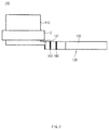
- FIG. 2 is a plan view illustrating a state before the electrode lead illustrated in FIG. 1 is assembled
- FIG. 3 is a rear view illustrating the state before the electrode lead illustrated in FIG. 1 is assembled
- FIG. 4 is a plan view illustrating a state in which the electrode lead and the pouch case illustrated in FIG. 1 are coupled to each other.
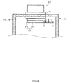
- FIG. 5A is a cross-sectional view taken along line A-A of FIG. 4 , illustrating a state in which the battery cell illustrated in FIG. 1 is normal
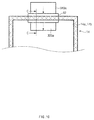
- FIG. 5B is a cross-sectional view taken along line A-A of FIG. 4 , illustrating a state in which the battery cell illustrated in FIG. 1 is expanded and thus the electrode lead is cut
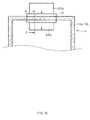
- FIG. 5C is a cross-sectional view taken along line A-A of FIG. 4 , illustrating a state in which the battery cell illustrated in FIG. 1 is contracted after being expanded.
- the battery cell 10 may include: the electrode assembly 11; the pouch case 14 that accommodates the electrode assembly 11 therein; and the electrode lead 100 including an outer lead 110 that protrudes outside the pouch case 14 and an inner lead 120 disposed between the outer lead 110 and the electrode assembly 11, accommodated in the pouch case 14, and cut by tension applied when the pouch case 14 is expanded.
- the battery cell 10 may include: the electrode assembly 11; the pouch case 14 that accommodates the electrode assembly 11 therein; and the electrode lead 100 including an outer lead 110 that protrudes outside the pouch case 14 and an inner lead 120 disposed between the outer lead 110 and the electrode assembly 11, accommodated in the pouch case 14, having a notch formed therein, and having a first side coupled to the pouch case 14 and a second side separated from the pouch case 14 based on the notch.
- the pouch case 14 may be formed of the first and second surfaces 14a and 14b facing each other, and the inner lead 120 may include a first inner lead 121 connected to the outer lead 110 and coupled to the first surface 14a; and a second inner lead 122 connected to the first inner lead 121, coupled to the second surface 14b, and connected to the electrode assembly 11. At least one of the first and second inner leads 121 and 122 may be formed of a plastic material that is plastically deformed by expansion of the pouch case 14.
- a pouch adhesive layer 170 that adheres the pouch case 14 and the inner lead 120 to each other may be formed in at least one of a space between the first surface 14a and the first inner lead 121 and a space between the second surface 14b and the second inner lead 122.
- the pouch adhesive layer 170 may be formed between some region of the first inner lead 121 adjacent to a bending part 160 to be described below and the first surface 14a and between the second inner lead 122 and the second surface 14b.
- an empty space in which the pouch adhesive layer 170 is not interposed may be formed between the first inner lead 121 and the first surface 14a.
- the inner lead 120 may include a weak part 130 formed in a portion that is not coupled to the pouch case 14 by the pouch adhesive layer 170 and having high brittleness compared to other portions of the inner lead 120.
- the weak part may be formed in a portion of the first inner lead 121 corresponding to the empty space formed between the first inner lead 121 and the first surface 14a.
- the notch may be formed in the weak part 130 and may have a groove shape or have apertures formed at a predetermined interval. The notch promotes fracture of the electrode lead 100.
- the first and second inner leads 121 and 122 may be disposed to overlap each other as illustrated in FIG. 5A .
- a lead adhesive layer 140 having an insulating and adhesive ingredient may be formed between the first and second inner leads 121 and 122.
- the lead adhesive layer 140 may be formed between a portion of the first inner lead 121 that is not attached to the first surface 14a by the pouch adhesive layer 170 and not provided with the weak part 130 and the second inner lead 122.
- An insulator 150 that insulates the first and second inner leads 121 and 122 from each other may be disposed between the first and second inner leads 121 and 122.
- the insulator 150 may be disposed in a portion in which the lead adhesive layer 140 is not provided in a region between the first and second inner leads 121 and 122, as illustrated in FIG. 5A .
- the lead adhesive layer 140 maybe disposed at a first side and the insulator 150 maybe disposed at a second side based on the weak part 130 between the first and second inner leads 121 and 122.
- the inner lead 120 may further include the bending part 160 that connects the first and second inner leads 121 and 122 and thus, the first and second inner leads 121 and 122 may be integrated with each other.
- the bending part 160 may be bent with a first end of the first inner lead 121 attached to the first surface 14a by the pouch adhesive layer 170 and a second end of the second inner lead 122 attached to the second surface 14b by the pouch adhesive layer 170 connected to each other, and the first and second inner leads 121 and 122 may be disposed to overlap each other, as illustrated in FIG. 5A .
- An inner surface of the bending part 160 may be disposed to face the insulator 150.
- the pouch case 14 may expand, and the first and second surfaces 14a and 14b may move away from each other (e.g., may be spaced apart).
- the first inner lead 121 may move together with the first surface 14a and the second inner lead 122 may move together with the second surface 14b by the pouch adhesive layer 170.
- the bending part 160 may be bent to be opened to space the first and second inner leads 121 and 122 apart from each other.
- a first portion of the first inner lead 121 may be attached to the first surface 14a by the pouch adhesive layer 170, and a second portion of the first inner lead 121 may be attached to the second inner lead 122 by the lead adhesive layer 140. Therefore, a first portion of the first inner lead 121 may move together with the first surface 14a, a second portion of the first inner lead 121 may move together with the second surface 14b. In other words, when the pouch case 14 expands, the first portion of the first inner lead 121 and the second portion of the first inner lead 121 may move in opposite directions to each other.
- the weak part 130 formed between the first portion of the first inner lead 121 and the second portion of the first inner lead 121 may be fractured by tension, that is, fracture force, applied to the weak part 130 when the pouch case 14 expands. Therefore, functions of the first and second inner leads 121 and 122 as conducting wires may be lost by the fracture of the weak part 130 as described above, and a current passing through the electrode lead 100 maybe blocked.
- the weak part 130 and the bending part 160 are separately formed is illustrated in FIGS. 2 to 5C , the weak part 130 may be formed in the bending part 160.
- an end portion of the pouch adhesive layer 170 may serve as a hinge axis.
- the insulator 150 may be omitted, and the first and second inner leads 121 and 122 may be bonded to each other by a compression method.
- the first and second inner leads 121 and 122 may be seated from the weak part 130 to the bending part 160 to be conductively bonded.
- a current flowing through the weak part 130 does not flow toward the bending part 160 but directly flows toward the second inner lead 122.
- a length of a conducting wire may decrease due to absence of the insulator 150. In other words, since a current path decrease, resistance may decrease.
- FIG. 6 is a plan view of a battery cell according to a second exemplary embodiment of the present disclosure
- FIG. 7 is a plan view illustrating a state before an electrode lead illustrated in FIG. 6 is assembled
- FIG. 8 is a rear view illustrating the state before the electrode lead illustrated in FIG. 6 is assembled.
- FIG. 9A is a cross-sectional view taken along line B-B of FIG. 6 , illustrating a state in which the battery cell illustrated in FIG. 6 is normal
- FIG. 9B is a cross-sectional view taken along line B-B of FIG. 6 , illustrating a state in which the battery cell illustrated in FIG. 6 is expanded and thus the electrode lead is cut
- FIG. 9C is a cross-sectional view taken along line B-B of FIG. 6 , illustrating a state in which the battery cell illustrated in FIG. 6 is contracted after being expanded.
- the battery cell 10 may include: an electrode assembly 11; a pouch case 14 that accommodates the electrode assembly 11 therein; and an electrode lead 200 including an outer lead 210 that protrudes outside the pouch case 14 and an inner lead 220 disposed between the outer lead 210 and the electrode assembly 11, accommodated in the pouch case 14, and cut by tension applied when the pouch case 14 is expanded.
- the battery cell 10 may include: the electrode assembly 11; the pouch case 14 that accommodates the electrode assembly 11 therein; and the electrode lead 200 including the outer lead 210 that protrudes outside the pouch case 14 and the inner lead 220 disposed between the outer lead 210 and the electrode assembly 11 and accommodated in the pouch case 14, wherein the inner lead 220 may include first and second inner leads 221 and 222 coupled to the pouch case 14, respectively, and overlapping each other.
- the pouch case 14 may have first and second surfaces 14a and 14b facing each other.
- the inner lead 220 may include the first inner lead 221 connected to the outer lead 210 and coupled to the first surface 14a; the second inner lead 222 connected to the electrode assembly 11 and coupled to the second surface 14b; a bending part 260 connecting the first and second inner leads 221 and 222 to each other; and a weak part 230 formed in the bending part 260.
- Pouch adhesive layers 270 that adhere the pouch case 14 and the inner lead 220 to each other may be formed between the first surface 14a and the first inner lead 221 and between the second surface 14b and the second inner lead 222, respectively.
- the first and second inner leads 221 and 222 may overlap each other as illustrated in FIG. 9A .
- At least one of the first and second inner leads 221 and 222 may be formed of a plastic material plastically deformed by expansion of the pouch case 14.
- a lead adhesive layer 240 having an insulating and adhesive ingredient may be formed between the first and second inner leads 221 and 222.
- the bending part 260 may connect a first end of the first inner lead 221 and a first of the second inner lead 222 to integrate the first and second inner leads 221 and 222 with each other, and the bending part 260 may be bent to overlap the first and second inner leads 221 and 222.
- An inner surface of the bending part 260 may be disposed to face the lead adhesive layer 240.
- the weak part 230 may be provided in an outer surface of the bending part 260 as illustrated in FIG. 9A .
- a notch may be formed in the weak part 230 and may have a groove shape or may include apertures formed at a predetermined interval. The notch promotes fracture of the electrode lead 200.
- the pouch case 14 may expand, and the first and second surfaces 14a and 14b may move apart (e.g., may become spaced apart).
- the first inner lead 221 may move together with the first surface 14a and the second inner lead 222 may move together with the second surface 14b by the pouch adhesive layer 270. Therefore, as illustrated in FIG.
- the bending part 260 may be bent to be opened and thus, the first and second inner leads 221 and 222 maybe spaced apart from each other, and the weak part 230 may be fractured by tension, that is, fracture force, applied to the weak part 230 while the bending part 260 is opened. Therefore, functions of the first and second inner leads 221 and 222 as conducting wires may be lost by the fracture of the weak part 230 as described above, and a current passing through the electrode lead 200 may be blocked.
- the weak part 230 may be formed in a connection point of the first and second inner leads 221 and 222, a separate insulator may be omitted and thus, a length of a conducting wire may be decreased due to absence of the insulator. In other words, since a current path is decreased, resistance maybe decreased.
- FIG. 10 is a plan view of a battery cell according to a third exemplary embodiment of the present disclosure
- FIG. 11 is a plan view illustrating a state before an electrode lead illustrated in FIG. 10 is assembled.
- FIG. 12A is a cross-sectional view taken along line C-C of FIG. 10 , illustrating a state in which the battery cell illustrated in FIG. 10 is normal
- FIG. 12B is a cross-sectional view taken along line C-C of FIG. 10 , illustrating a state in which the battery cell illustrated in FIG. 10 is expanded and thus the electrode lead is cut
- FIG. 12C is a cross-sectional view taken along line C-C of FIG. 10 , illustrating a state in which the battery cell illustrated in FIG. 10 is contracted after being expanded.
- the battery cell 10 may include: an electrode assembly 11; a pouch case 14 that accommodates the electrode assembly 11 therein; and an electrode lead 300a including an outer lead 310a that protrudes outside the pouch case 14 and an inner lead 320a disposed between the outer lead 310a and the electrode assembly 11, accommodated in the pouch case 14, disposed in parallel with a straight line (not illustrated) connecting the electrode assembly 11 and the outer lead 310a at a shortest distance, and cut by expansion force of the pouch case 14.
- the battery cell 10 may include: the electrode assembly 11; the pouch case 14 that accommodates the electrode assembly 11 therein; and the electrode lead 300a including the outer lead 310a that protrudes outside the pouch case 14 and the inner lead 320a disposed between the outer lead 310a and the electrode assembly 11 and accommodated in the pouch case 14.
- the inner lead 320a may be coupled to first and second surfaces 14a and 14b of the pouch case 14 and bent in a 'S' shape.
- the inner lead 320a may include a first inner lead 321a connected to the outer lead 310a and coupled to the first surface 14a; a second inner lead 322a coupled to the second surface 14b and connected to the electrode assembly 11; an intermediate lead 323a disposed between the first and second inner leads 321a and 322a; bending parts 360a and 360a' that connect the first inner lead 321a and the intermediate lead 323a to each other and that connect the second inner lead 322a and the intermediate lead 323a to each other, respectively; and a weak part 330a provided in the second inner lead 322a.
- the bending parts 360a and 360a' may be bent with the first inner lead, the intermediate lead, and the second inner lead 321a, 323a, and 322a disposed to overlap each other, thus forming the inner lead 320a as an 'S' shape.
- At least a portion of the inner lead 320a may be made of a plastic material plastically deformed by expansion of the pouch case 14.
- Pouch adhesive layers 370a and 370a' that adhere the pouch case 14 and the inner lead 320a to each other may be formed between the first surface 14a and the first inner lead 321a and between the second surface 14b and the second inner lead 322a, respectively.
- a lead adhesive layer 340a having an insulation property and an adhesive property may be disposed in one of a space between the first inner lead 321a and the intermediate lead 323a and a space between the second inner lead 322a and the intermediate lead 323a, and an insulator 350a having an insulation property without an adhesive property is disposed in the other of the spaces.
- the lead adhesive layer 340a may be disposed between the first inner lead 321a and the intermediate lead 323a
- the insulator 350a may be disposed between the intermediate lead 323a and the second inner lead 322a.
- FIG. 12A the lead adhesive layer 340a having an insulation property and an adhesive property may be disposed in one of a space between the first inner lead 321a and the intermediate lead 323a and a space between the second inner lead 322a and the intermediate lead 323a.
- the lead adhesive layer 340a may be disposed between another portion of the second inner lead 322a positioned toward the electrode assembly 11 compared to a first portion of the second inner lead 322a attached to the second surface 14b by the pouch adhesive layer 370a and a first portion of the intermediate lead 323a provided with the bending part 360a.
- the first portion of the second inner lead 322a may not be attached to the intermediate lead 323a, and the second portion of the second inner lead 322a may be attached to the intermediate lead 323a.
- the weak part 330a may be disposed between a first portion of the second inner lead 322a and a second portion of the second inner lead 322a.
- a notch may be formed in the weak part 330a and the notch may include a groove shape or apertures formed at a predetermined interval. The notch may promote fracture of the electrode lead 300a when the pouch case 14 expands.
- FIG. 12A when the battery cell 10 operates normally, since there is no gas in the battery cell 10, a state in which the first inner lead, the second inner lead, and the intermediate lead 321 a, 322a, and 323a overlap each other may be maintained.
- the pouch case 14 may expand, and the first and second surfaces 14a and 14b may become spaced apart.
- the first inner lead 321a may move together with the first surface 14a and the second inner lead 322a may move together with the second surface 14b by the pouch adhesive layers 370a and 370a'.
- a first portion of the second inner lead 322a and the intermediate lead 323a may be separated from each other by the insulator 350a, a second portion of the second inner lead 322a and the intermediate lead 323a may be coupled to each other by the lead adhesive layer 340a, and the first inner lead 321a and the intermediate lead 323a may be coupled to each other by the lead adhesive layer 340a. Therefore, the first portion of the second inner lead 322a may move together with the second surface 14b, and the second portion of the second inner lead 322a may move together with the first surface 14a. In other words, when the pouch case 14 expands, the first portion of the second inner lead 322a and the second portion of the second inner lead 322a may move in opposite directions to each other.
- the bending part 360a' when the pouch case 14 expands, the bending part 360a' may be bent to be opened and thus, the portion of the second inner lead 322a and the intermediate lead 323a may be spaced apart from each other.
- the weak part 330a disposed between the first portion of the second inner lead 322a and the second portion of the second inner lead 322a may be fractured by tension, that is, fracture force, applied when the pouch case 14 expands. Therefore, a function of the electrode lead 300a as a conducting wire may be lost by the fracture of the weak part 330a as described above, and a current passing through the electrode lead 300a may be blocked.
- the electrode lead 300a is not limited thereto. In other words, the electrode lead 300a may be provided in which the first inner lead 321a may be fractured when the pouch case 14 expands.
- FIG. 13 is a plan view of a battery cell according to a fourth exemplary embodiment of the present disclosure
- FIG. 14 is a plan view illustrating a state before an electrode lead illustrated in FIG. 13 is assembled.
- FIG. 15A is a cross-sectional view taken along line D-D of FIG. 13 , illustrating a state in which the battery cell illustrated in FIG. 13 is normal
- FIG. 15B is a cross-sectional view taken along line D-D of FIG. 13 , illustrating a state in which the battery cell illustrated in FIG. 13 is expanded and thus the electrode lead is cut
- FIG. 15C is a cross-sectional view taken along line D-D of FIG. 13 , illustrating a state in which the battery cell illustrated in FIG. 13 is contracted after being expanded.
- the battery cell 10 may include: an electrode assembly 11; a pouch case 14 that accommodates the electrode assembly 11 therein; and an electrode lead 300b including an outer lead 310b that protrudes outside the pouch case 14 and an inner lead 320b disposed between the outer lead 310b and the electrode assembly 11, accommodated in the pouch case 14, disposed in parallel with a straight line (not illustrated) connecting the electrode assembly 11 and the outer lead 310b at a shortest distance, and cut by expansion force of the pouch case 14.
- the battery cell 10 may include: the electrode assembly 11; the pouch case 14 that accommodates the electrode assembly 11 therein; and the electrode lead 300b including the outer lead 310b that protrudes outside the pouch case 14 and the inner lead 320b disposed between the outer lead 310b and the electrode assembly 11 and accommodated in the pouch case 14.
- the inner lead 320b may be coupled to first and second surfaces 14a and 14b of the pouch case 14 and bent in a'S' shape.
- the inner lead 320b may include a first inner lead 321b connected to the outer lead 310b and coupled to the first surface 14a; a second inner lead 322b coupled to the second surface 14b and connected to the electrode assembly 11; an intermediate lead 323b disposed between the first and second inner leads 321b and 322b; bending parts 360b and 360b' that connect the first inner lead 321b and the intermediate lead 323b to each other and that connect the second inner lead 322b and the intermediate lead 323b to each other, respectively; and a weak part 330b disposed in the bending part 360b.
- the bending parts 360b and 360b' may be bent with the first inner lead, the intermediate lead, and the second inner lead 321b, 323b, and 322b disposed to overlap each other, and the inner lead 320b may form an 'S' shape.
- At least a portion of the inner lead 320b may be made of a plastic material plastically deformed by expansion of the pouch case 14.
- Pouch adhesive layers 370b and 370b' that adhere the pouch case 14 and the inner lead 320b to each other may be formed between the first surface 14a and the first inner lead 321b and between the second surface 14b and the second inner lead 322b, respectively.
- a lead adhesive layer 340b having an insulation property and an adhesive property may be disposed in one of a space between the first inner lead 321b and the intermediate lead 323b and a space between the second inner lead 322b and the intermediate lead 323b, and an insulator 350b having an insulation property without an adhesive property may be disposed in the other of the spaces.
- the lead adhesive layer 340b may be disposed between the second inner lead 322b and the intermediate lead 323b
- the insulator 350b may be disposed between the intermediate lead 323b and the first inner lead 321b.
- FIG. 15A the lead adhesive layer 340b having an insulation property and an adhesive property may be disposed in one of a space between the first inner lead 321b and the intermediate lead 323b and a space between the second inner lead 322b and the intermediate lead 323b
- an insulator 350b having an insulation property without an adhesive property may be disposed in the other of the spaces.
- the lead adhesive layer 340b may be disposed between the second inner lead 322
- the lead adhesive layer 340b may be disposed between a second portion of the first inner lead 321b positioned toward the outer lead 310b compared to a first portion of the first inner lead 321b attached to the first surface 14a by the pouch adhesive layer 370b and a first end portion of the intermediate lead 323b provided with the bending part 360b'.
- a first portion of the first inner lead 321b may not be attached to the intermediate lead 323b, and a second portion of the first inner lead 321b may be attached to the intermediate lead 323b.
- the weak part 330b may be provided in the bending part 360b as illustrated in FIG. 15A .
- a notch may be formed in the weak part 330b and the notch may include a groove shape or apertures formed at a predetermined interval. The notch may promote fracture of the electrode lead 300b when the pouch case 14 expands.
- FIG. 15A when the battery cell 10 operates normally, since there is no gas in the battery cell 10, a state in which the first inner lead, the second inner lead, and the intermediate lead 321b, 322b, and 323b overlap each other may be maintained. However, when the battery cell 10 starts to be filled with gas due to overcharge, the pouch case 14 may expand, and the first and second surfaces 14a and 14b may become spaced apart. In particular, as illustrated in FIG. 15B , the first inner lead 321b may move together with the first surface 14a and the second inner lead 322b may move together with the second surface 14b by the pouch adhesive layers 370b and 370b'.
- a first portion of the first inner lead 321b and the intermediate lead 323b may be separated from each other by the insulator 350b, a second portion of the first inner lead 321b and the intermediate lead 323b may be coupled to each other by the lead adhesive layer 340b, and the second inner lead 322b and the intermediate lead 323b may be coupled to each other by the lead adhesive layer 340b. Therefore, the first portion of the first inner lead 321b may move together with the first surface 14a, and the second portion of the first inner lead 321b may move together with the second surface 14b. In other words, when the pouch case 14 expands, the first portion of the first inner lead 321b and the second portion of the first inner lead 321b may move in opposite directions to each other.
- the bending part 360b when the pouch case 14 expands, the bending part 360b may be bent to be opened and thus, the first portion of the first inner lead 321b and the intermediate lead 323b may be spaced apart from each other.
- the weak part 330b may be fractured by tension, that is, fracture force, applied when the bending part 360b is opened. Therefore, a function of the electrode lead 300b as a conducting wire may be lost by the fracture of the weak part 330b as described above, and a current passing through the electrode lead 300b may be blocked.
- the electrode lead 300b is not limited thereto. In other words, the electrode lead 300b may be provided with the bending part 360b' fractured when the pouch case 14 expands.
- FIG. 16 is a plan view of a battery cell according to a fifth exemplary embodiment of the present disclosure
- FIG. 17 is a plan view illustrating a state before an electrode lead illustrated in FIG. 16 is assembled.
- FIG. 18A is a cross-sectional view taken along line E-E of FIG. 16 , illustrating a state in which the battery cell illustrated in FIG. 16 is normal
- FIG. 18B is a cross-sectional view taken along line E-E of FIG. 16 , illustrating a state in which the battery cell illustrated in FIG. 16 is expanded and thus the electrode lead is cut
- FIG. 18C is a cross-sectional view taken along line E-E of FIG. 16 , illustrating a state in which the battery cell illustrated in FIG. 16 is contracted after being expanded.
- an inner lead 320c may include a first inner lead 321c connected to an outer lead 310c; a second inner lead 322c electrically connected to an electrode tap T of an electrode assembly 11; and a weak part 330c disposed between the first and second inner leads 321c and 322c.
- the inner lead 320c may be formed to dispose the first and second inner leads 321c and 322c on a linear line.
- the inner lead 320c may be disposed in a pouch case 14 when the linear line is maintained without an overlapping section.
- the inner lead 320c as described above may minimize a length of a path through which a current flows to decrease resistance compared to the inner leads according to the second and third exemplary embodiments of the present disclosure described above. Further, at least a portion of the inner lead 320c may be made of a plastic material plastically deformed by expansion of the pouch case 14.
- An insulator 350c having an insulation property without an adhesive property may be disposed between the first inner lead 321c and a first surface 14a, and a pouch adhesive layer 370c having an insulation property and an adhesive property may be disposed between the first inner lead 321c and a second surface 14b.
- the pouch adhesive layer 370c and the insulator 350c may be disposed to face each other with the first inner lead 321c interposed therebetween.
- the first inner lead 321c may be separated from the first surface 14a by the insulator 350c and coupled to the second surface 14b by the pouch adhesive layer 370c.
- a pouch adhesive layer 370c' having the insulation property and the adhesive property may be disposed between the second inner lead 322c and the first surface 14a, and an insulator 350c' having the insulation property without the adhesive property may be disposed between the second inner lead 322c and the second surface 14b. Additionally, the pouch adhesive layer 370c' and the insulator 350c' may be disposed to face each other with the second inner lead 322c interposed therebetween. Particularly, the second inner lead 322c may be coupled to the first surface 14a by the pouch adhesive layer 370c' and may be separated from the second surface 14b by the insulator 350c'.
- the space between the pouch case 14 and the inner lead 320c may be narrow at a position at which the electrode tap T is disposed, and thus, deformation of an electrode lead 300c may be resisted. Therefore, the pouch adhesive layers 370c and 370c' and the insulators 350c and 350c' may be disposed to separate the electrode lead 300c from the electrode tap T.
- disposition areas of the pouch adhesive layers 370c and 370c' and the insulators 350c and 350c' or degrees of adhesion of the pouch adhesive layers 370c and 370c' may be determined based on durability of the battery cell 10 and ease of fracture of the electrode lead 300c.
- An exemplary embodiment in which the insulator 350c and the pouch adhesive layer 370c are formed to have wider areas than those of the insulator 350c' and the pouch adhesive layer 370c' based on the weak part 330c is illustrated in FIG. 18A .
- a fracture property of the electrode lead 300c maybe improved.
- the weak part 330c may be disposed between the first and second inner leads 321c and 322c as illustrated in FIG. 18A .
- the weak part 330c may be disposed not to be covered by the pouch adhesive layers 370c and 370c' and the insulators 350c and 350c' (e.g., remains exposed).
- the insulators 350c and 350c' may be positioned in a diagonal direction based on the weak part 330c
- the pouch adhesive layers 370c and 370c' may be positioned in a diagonal direction based on the weak part 330c.
- the insulators 350c and 350c' and the pouch adhesive layers 370c and 370c' may be disposed to alternate with each other based the weak part 330c.
- a notch may be formed in the weak part 330c to decrease a thickness or width of the inner lead 320c.
- a point in time of fracture of the inner lead 320c may be adjusted by a thickness or width of the notch. For example, a depth of a notch of the weak part 330c fractured when a voltage of the battery cell 10 is about 5V may be greater than that of a notch of the weak part 330c fractured when the voltage of the battery cell 10 is about 6V.
- the pouch case 14 when the battery cell 10 starts to be filled with gas due to overcharge, the pouch case 14 may expand, and the first and second surfaces 14a and 14b may be separated apart.
- the first inner lead 321c may move together with the second surface 14b by the pouch adhesive layer 370c
- the second inner lead 322c may move together with the first surface 14a by the pouch adhesive layer 370c'.
- the pouch adhesive layers 370c and 370c' may be positioned in the diagonal direction based on the weak part 330c. Therefore, the weak part 330c may be fractured by tension, that is, fracture force, applied when the pouch case 14 expands.
- a function of the electrode lead 300c as a conducting wire may be lost by the fracture of the weak part 330c as described above, and a current passing through the electrode lead 300c may be blocked. Thereafter, as illustrated in FIG. 18C , even though the pouch case 14 is contracted, an open shape of the electrode lead 300c of which at least a portion is made of the plastic material may be maintained as it is. Therefore, even though an abnormal state is terminated, an over-current may be prevented from flowing to the electrode assembly 11 again, and usage safety of the battery cell 10 maybe secured.
- FIG. 19 is a plan view of a battery cell according to a sixth exemplary embodiment of the present disclosure
- FIG. 20 is a plan view illustrating a case in which the sixth exemplary embodiment of the present disclosure is applied to a battery cell in which a plurality of electrode leads are formed on one side of an electrode assembly.
- FIG. 21A is a cross-sectional view taken along line F-F of FIG. 19 , illustrating a state in which the battery cell illustrated in FIG. 19 is normal
- FIG. 21B is a cross-sectional view taken along line F-F of FIG. 19 , illustrating a state in which the battery cell illustrated in FIG. 19 is expanded and thus the electrode lead is cut
- FIG. 21C is a cross-sectional view taken along line F-F of FIG. 19 , illustrating a state in which the battery cell illustrated in FIG. 19 is contracted after being expanded.
- an inner lead 420 may be formed to be elongated in a left-right direction.
- an outer lead 410 may be formed to be elongated in a front and rear direction, and the inner lead 420 may be formed in the left and right direction.
- the inner lead 420 may be formed in a linear shape without an overlapping or bending section.
- a first end of the inner lead 420 may be connected to the outer lead 410, and a second end of the inner lead 420 may be connected to an electrode tap T.
- a planar shape of the inner lead 420 is similar to those in the first and second exemplary embodiments of the present disclosure, and a cross-sectional shape of the inner lead 420 is similar to that in the fifth exemplary embodiment of the present disclosure.
- the inner lead 420 may include a first inner lead 421 connected to the outer lead 410; a second inner lead 422 electrically connected to the electrode tap T of the electrode assembly 11; and a weak part 430 disposed between the first and second inner leads 421 and 422.
- An insulator 450 having an insulation property without an adhesive property may be disposed between the first inner lead 421 and a first surface 14a, and a pouch adhesive layer 470 having an insulation property and an adhesive property may be disposed between the first inner lead 421 and a second surface 14b.
- the pouch adhesive layer 470 and the insulator 450 may be disposed to face each other with the first inner lead 421 interposed therebetween.
- the first inner lead 421 may be separated from the first surface 14a by the insulator 450 and coupled to the second surface 14b by the pouch adhesive layer 470.
- a pouch adhesive layer 470' having the insulation property and the adhesive property may be disposed between the second inner lead 422 and the first surface 14a, and an insulator 450' having the insulation property without the adhesive property may be disposed between the second inner lead 422 and the second surface 14b.
- the pouch adhesive layer 470' and the insulator 450' may be disposed to face each other with the second inner lead 422 interposed therebetween.
- the second inner lead 422 may be coupled to the first surface 14a by the pouch adhesive layer 470' and may be separated from the second surface 14b by the insulator 450'.
- the weak part 430 may be disposed between the first and second inner leads 421 and 422 as illustrated in FIG. 21A .
- the weak part 430 may be provided so as not to be covered by the pouch adhesive layers 470 and 470' and the insulators 450 and 450' (e.g., the weak part 430 may be exposed).
- a notch may be formed in the weak part 430 to decrease a thickness or width of the inner lead 420.
- the pouch case 14 when the battery cell 10 starts to be filled with gas due to overcharge, the pouch case 14 may expand, and the first and second surfaces 14a and 14b may be from each other.
- the first inner lead 421 may move together with the second surface 14b by the pouch adhesive layer 470
- the second inner lead 422 may move together with the first surface 14a by the pouch adhesive layer 470'.
- the pouch adhesive layers 470 and 470'a may be positioned in a diagonal direction based on the weak part 430. Therefore, the weak part 430 may be fractured by tension, that is, fracture force, applied when the pouch case 14 expands. Therefore, a function of the electrode lead 400 as a conducting wire may be lost by the fracture of the weak part 430 as described above, and a current passing through the electrode lead 400 may be blocked.
- the battery cell 10 may be designed with the plurality of electrode leads 400 disposed at one side of the electrode assembly 11 by suitably adjusting disposition of an inner lead 420 in which a notch may be formed and another inner lead 420 in which the notch is not formed.
- the battery cell may provide one or more of the following advantageous effects.
- the electrode lead capable of automatically blocking the current applied to the battery cell during overcharge of the battery cell is provided.
- the electrode lead may mechanically operate without the separate power source or control part to block the current applied to the battery cell.
- the electrode lead capable of having a current blocking function and being integrally manufactured is provided.
- the length of the electrode lead may be decreased, to thus decrease resistance.
Landscapes
- Chemical & Material Sciences (AREA)
- Chemical Kinetics & Catalysis (AREA)
- Electrochemistry (AREA)
- General Chemical & Material Sciences (AREA)
- Engineering & Computer Science (AREA)
- Manufacturing & Machinery (AREA)
- Materials Engineering (AREA)
- Connection Of Batteries Or Terminals (AREA)
- Sealing Battery Cases Or Jackets (AREA)
- Secondary Cells (AREA)
Abstract
Description
- The present disclosure relates to a battery cell, and more particularly, to a pouch type battery cell capable of blocking a current flow when overcharge occurs.
- Since use of portable electric products such as a video camera, a portable phone, a portable personal computer (PC), and the like, has been activated, an importance of a secondary battery mainly used as a driving power source has increased. Research has been actively conducted regarding a secondary battery capable of being charged and discharged unlike a primary battery that cannot be generally recharged in accordance with the development of a digital camera, a cellular phone, a laptop computer, a power tool, an electric bike, an electric vehicle, a hybrid vehicle, a large-capacity power storage device, and the like, in high-tech fields.
- Particularly, since a lithium secondary battery has a high energy density per unit weight and is capable of being rapidly charged, compared to other secondary batteries such as an existing lead-acid battery, a nickel-cadmium battery, a nickel-hydrogen battery, a nickel-zinc battery, and the like, use of the lithium secondary battery has actively increased. An operation voltage of the lithium secondary battery is 3.6V or greater, and the lithium secondary battery has been used as a power source of portable electronic equipment. Alternatively, a plurality of lithium secondary batteries are connected with each other in series or in parallel to be used in a high-power electric vehicle, a hybrid vehicle, a power tool, an electric bike, power storage device, an uninterruptible power supply (UPS), and the like.
- Since the lithium secondary battery has an operation voltage 3 times greater than that of the nickel-cadmium battery or nickel-metal hybrid battery, and has improved energy density characteristics per unit weight, the use of the lithium secondary battery has rapidly increased. Further, a lithium ion battery using a liquid electrolyte has been used in a form in which the lithium secondary battery is welded and sealed using a cylindrical or prismatic metal can as a container. Since a shape of a can type secondary battery using this metal can as the container is fixed, there is a disadvantage in that a design of an electric product using the can type secondary battery as a power source is restricted, and it may be difficult to decrease a volume thereof Therefore, a power type secondary battery used in a form in which an electrode assembly and an electrolyte are put into a pouch package made of a film and sealed has been developed and used.
- However, since the lithium secondary battery has a risk of explosion when the lithium secondary battery is over-heated, it is important to secure safety. Overheating of the lithium secondary battery may be generated by various causes. For example, the lithium secondary battery may be overheated during an over-current exceeding a limit value flows through the lithium secondary battery. When the over-current flows, since heat is generated in the lithium secondary battery by Joule's heat, an internal temperature of the battery is rapidly increased. Further, a rapid increase in the temperature causes a decomposition reaction of the electrolyte solution to cause a thermal runaway phenomenon, thereby finally causing explosion of the battery. The over-current may be generated when a shape metal object penetrates through the lithium secondary battery, insulation between a cathode and an anode is broken by shrinkage of a separator interposed between the cathode and the anode, or a rush current is applied to the battery due to abnormality of a charge circuit connected to the outside or abnormality of load, or the like.
- Therefore, the lithium secondary battery is coupled to a protection circuit to protect the battery from an abnormal situation such as generation of the over-current to be used, and in general, the protection circuit includes a fuse element irreversibly disconnecting a line in which a charge or discharge current flows when the over-current is generated. However, when malfunction of the fuse element occurs, an internal pressure of the lithium secondary battery configuring a battery module and/or a battery pack, that is, a battery cell may be continuously increased, causing a risk of ignition or explosion, or the like. Therefore, there is a need to more clearly block a current flow to secure safety at the time of an increase in internal pressure of the battery cell.
- The present disclosure has been made to solve the above-mentioned problems occurring in the prior art while advantages achieved by the prior art are maintained intact.
- First, an aspect of the present disclosure provides an electrode lead capable of automatically blocking a current applied to a battery cell at the time of overcharge of the battery cell.
- Second, an aspect of the present disclosure provides an electrode lead capable of mechanically operating without a separate power source or a control part to block a current applied to a battery cell.
- Third, an aspect of the present disclosure provides an electrode lead capable of having a current blocking function and being integrally manufactured.
- Fourth, an aspect of the present disclosure provides a battery cell capable of minimizing a path through which a current flows to decrease resistance.
- Fifth, an aspect of the present disclosure provides a battery cell capable of more easily setting an operation voltage at which a current blocking function is operated.
- According to an exemplary embodiment of the present disclosure, a battery cell is provided that may include: an electrode assembly; a pouch case that accommodates the electrode assembly therein; and an electrode lead including an outer lead that protrudes outside the pouch case and an inner lead disposed between the outer lead and the electrode assembly, accommodated in the pouch case, and cut by tension applied when the pouch case is expanded.
- According to another exemplary embodiment of the present disclosure, a battery cell is provided that may include: an electrode assembly; a pouch case that accommodates the electrode assembly therein; and an electrode lead including an outer lead that protrudes outside the pouch case and an inner lead disposed between the outer lead and the electrode assembly and accommodated in the pouch case, wherein the inner lead is disposed between first and second surfaces of the pouch case when the inner lead is bent in a `S' shape, coupled to the first and second surfaces by a pouch adhesive layer, respectively, and includes a weak part provided to be fractured by tension applied to the inner lead when the pouch case is expanded. Details of exemplary embodiments will be described below with reference to the accompanying drawings.
- The above and other objects, features and advantages of the present disclosure will be more apparent from the following detailed description taken in conjunction with the accompanying drawings.
-
FIG. 1 is a plan view of a battery cell according to a first exemplary embodiment of the present disclosure; -
FIG. 2 is a plan view illustrating a state before an electrode lead illustrated inFIG. 1 is assembled according to an exemplary embodiment of the present disclosure; -
FIG. 3 is a rear view illustrating the state before the electrode lead illustrated inFIG. 1 is assembled according to an exemplary embodiment of the present disclosure; -
FIG. 4 is a plan view illustrating a state in which the electrode lead and a pouch case illustrated inFIG. 1 are coupled to each other according to an exemplary embodiment of the present disclosure; -
FIG. 5A is a cross-sectional view taken along line A-A ofFIG. 4 , illustrating a state in which the battery cell illustrated inFIG. 1 is normal according to an exemplary embodiment of the present disclosure; -
FIG. 5B is a cross-sectional view taken along line A-A ofFIG. 4 , illustrating a state in which the battery cell illustrated inFIG. 1 is expanded and thus the electrode lead is cut according to an exemplary embodiment of the present disclosure; -
FIG. 5C is a cross-sectional view taken along line A-A ofFIG. 4 , illustrating a state in which the battery cell illustrated inFIG. 1 is contracted after being expanded according to an exemplary embodiment of the present disclosure; -
FIG. 6 is a plan view of a battery cell according to a second exemplary embodiment of the present disclosure; -
FIG. 7 is a plan view illustrating a state before an electrode lead illustrated inFIG. 6 is assembled according to an exemplary embodiment of the present disclosure; -
FIG. 8 is a rear view illustrating the state before the electrode lead illustrated inFIG. 6 is assembled according to an exemplary embodiment of the present disclosure; -
FIG. 9A is a cross-sectional view taken along line B-B ofFIG. 6 , illustrating a state in which the battery cell illustrated inFIG. 6 is normal according to an exemplary embodiment of the present disclosure; -
FIG. 9B is a cross-sectional view taken along line B-B ofFIG. 6 , illustrating a state in which the battery cell illustrated inFIG. 6 is expanded and thus the electrode lead is cut according to an exemplary embodiment of the present disclosure; -
FIG. 9C is a cross-sectional view taken along line B-B ofFIG. 6 , illustrating a state in which the battery cell illustrated inFIG. 6 is contracted after being expanded according to an exemplary embodiment of the present disclosure; -
FIG. 10 is a plan view of a battery cell according to a third exemplary embodiment of the present disclosure. -
FIG. 11 is a plan view illustrating a state before an electrode lead illustrated inFIG. 10 is assembled according to an exemplary embodiment of the present disclosure; -
FIG. 12A is a cross-sectional view taken along line C-C ofFIG. 10 , illustrating a state in which the battery cell illustrated inFIG. 10 is normal according to an exemplary embodiment of the present disclosure; -
FIG. 12B is a cross-sectional view taken along line C-C ofFIG. 10 , illustrating a state in which the battery cell illustrated inFIG. 10 is expanded and thus the electrode lead is cut according to an exemplary embodiment of the present disclosure; -
FIG. 12C is a cross-sectional view taken along line C-C ofFIG. 10 , illustrating a state in which the battery cell illustrated inFIG. 10 is contracted after being expanded according to an exemplary embodiment of the present disclosure; -
FIG. 13 is a plan view of a battery cell according to a fourth exemplary embodiment of the present disclosure; -
FIG. 14 is a plan view illustrating a state before an electrode lead illustrated inFIG. 13 is assembled according to an exemplary embodiment of the present disclosure; -
FIG. 15A is a cross-sectional view taken along line D-D ofFIG. 13 , illustrating a state in which the battery cell illustrated inFIG. 13 is normal according to an exemplary embodiment of the present disclosure; -
FIG. 15B is a cross-sectional view taken along line D-D ofFIG. 13 , illustrating a state in which the battery cell illustrated inFIG. 13 is expanded and thus the electrode lead is cut according to an exemplary embodiment of the present disclosure; -
FIG. 15C is a cross-sectional view taken along line D-D ofFIG. 13 , illustrating a state in which the battery cell illustrated inFIG. 13 is contracted after being expanded according to an exemplary embodiment of the present disclosure; -
FIG. 16 is a plan view of a battery cell according to a fifth exemplary embodiment of the present disclosure; -
FIG. 17 is a plan view illustrating a state before an electrode lead illustrated inFIG. 16 is assembled according to an exemplary embodiment of the present disclosure; -
FIG. 18A is a cross-sectional view taken along line E-E ofFIG. 16 , illustrating a state in which the battery cell illustrated inFIG. 16 is normal according to an exemplary embodiment of the present disclosure; -
FIG. 18B is a cross-sectional view taken along line E-E ofFIG. 16 , illustrating a state in which the battery cell illustrated inFIG. 16 is expanded and thus the electrode lead is cut according to an exemplary embodiment of the present disclosure; -
FIG. 18C is a cross-sectional view taken along line E-E ofFIG. 16 , illustrating a state in which the battery cell illustrated inFIG. 16 is contracted after being expanded according to an exemplary embodiment of the present disclosure; -
FIG. 19 is a plan view of a battery cell according to a sixth exemplary embodiment of the present disclosure; -
FIG. 20 is a plan view illustrating a case in which the sixth exemplary embodiment of the present disclosure is applied to a battery cell in which a plurality of electrode leads are formed on one side of an electrode assembly according to an exemplary embodiment of the present disclosure; -
FIG. 21A is a cross-sectional view taken along line F-F ofFIG. 19 , illustrating a state in which the battery cell illustrated inFIG. 19 is normal according to an exemplary embodiment of the present disclosure; -
FIG. 21B is a cross-sectional view taken along line F-F ofFIG. 19 , illustrating a state in which the battery cell illustrated inFIG. 19 is expanded and thus the electrode lead is cut according to an exemplary embodiment of the present disclosure; and -
FIG. 21C is a cross-sectional view taken along line F-F ofFIG. 19 , illustrating a state in which the battery cell illustrated inFIG. 19 is contracted after being expanded according to an exemplary embodiment of the present disclosure. - It is understood that the term "vehicle" or "vehicular" or other similar term as used herein is inclusive of motor vehicles in general such as passenger automobiles including sports utility vehicles (SUV), buses, trucks, various commercial vehicles, watercraft including a variety of boats and ships, aircraft, and the like, and includes hybrid vehicles, electric vehicles, plug-in hybrid electric vehicles, hydrogen-powered vehicles and other alternative fuel vehicles (e.g. fuels derived from resources other than petroleum). As referred to herein, a hybrid vehicle is a vehicle that has two or more sources of power, for example both gasoline-powered and electric-powered vehicles.
- Although exemplary embodiment is described as using a plurality of units to perform the exemplary process, it is understood that the exemplary processes may also be performed by one or plurality of modules. Additionally, it is understood that the term controller/control unit refers to a hardware device that includes a memory and a processor. The memory is configured to store the modules and the processor is specifically configured to execute said modules to perform one or more processes which are described further below.
- The terminology used herein is for the purpose of describing particular embodiments only and is not intended to be limiting of the invention. As used herein, the singular forms "a", "an" and "the" are intended to include the plural forms as well, unless the context clearly indicates otherwise. It will be further understood that the terms "comprises" and/or "comprising," when used in this specification, specify the presence of stated features, integers, steps, operations, elements, and/or components, but do not preclude the presence or addition of one or more other features, integers, steps, operations, elements, components, and/or groups thereof. As used herein, the term "and/or" includes any and all combinations of one or more of the associated listed items.
- Unless specifically stated or obvious from context, as used herein, the term "about" is understood as within a range of normal tolerance in the art, for example within 2 standard deviations of the mean. "About" can be understood as within 10%, 9%, 8%, 7%, 6%, 5%, 4%, 3%, 2%, 1%, 0.5%, 0.1%, 0.05%, or 0.01% of the stated value. Unless otherwise clear from the context, all numerical values provided herein are modified by the term "about."
- Advantages and features of the present disclosure and methods to achieve them will be elucidated from exemplary embodiments described below in detail with reference to the accompanying drawings. However, the present disclosure is not limited to the exemplary embodiment disclosed herein but will be implemented in various forms. The exemplary embodiments make disclosure of the present disclosure thorough and are provided so that those skilled in the art can easily understand the scope of the present disclosure. Therefore, the present disclosure will be defined by the scope of the appended claims. Like reference numerals throughout the specification denote like elements.
- Hereinafter, battery cells according to exemplary embodiments of the present disclosure will be described with reference to the accompanying drawings.
FIG. 1 is a plan view of a battery cell according to a first exemplary embodiment of the present disclosure. Referring toFIG. 1 , thebattery cell 10 may include anelectrode assembly 11, a pair of electrode leads 100, an insulatingfilm 12, and apouch case 14. - The
electrode assembly 11 may include a cathode plate, an anode plate, a separator, and an electrode tap T. Theelectrode assembly 11 may be a stack type electrode assembly formed by interposing the separator between stacked cathode and anode plates. Further, theelectrode assembly 11 may be formed in a jelly-roll form. The cathode plate may be formed by applying a cathode active material on a current collector plate made of an aluminum (Al) material. Further, the anode plate may be formed by applying an anode active material on a current collector plate made of a copper (Cu) material. - The electrode tap T, formed integrally with an electrode plate, that is, the cathode plate or anode plate, corresponds to a non-coated region of the electrode plate on which an electrode active material is not applied. In other words, the electrode tap T may include a cathode tap that corresponds to a region of the cathode plate on which the cathode active material is not applied and an anode tap that corresponds to a region of the anode plate on which the anode active material is not applied. The
electrode lead 100, which is a thin plate-shaped metal, may be attached to the electrode tap T to be extended in an outward direction of theelectrode assembly 11. Theelectrode lead 100 may include a cathode lead attached to the cathode tap and an anode lead attached to the anode tap. The cathode and anode leads may be extended in the same direction as each other or in opposite directions to each other based on formation positions of the cathode and anode taps. - The insulating
film 12, attached to a circumference of theelectrode lead 100 in a width direction to be interposed between theelectrode lead 100 and an inner surface of thepouch case 14, may be made of a film having an insulation property and thermal bondability. The insulatingfilm 12 may be formed of, for example, a layer (e.g., single layer or multiple layer) of any one or more materials selected from polyimide (PI), polypropylene (PP), polyethylene (PE), polyethylene terephthalate (PET), and the like. The insulatingfilm 12 may prevent a short-circuit from occurring between theelectrode lead 100 and a metal layer of thepouch case 14. In addition, the insulatingfilm 12 may improve sealing power of thepouch case 14 in a region in which theelectrode lead 100 is led. - In other words, since the
electrode lead 100 made of a metal plate and the inner surface of thepouch case 14 are not appropriately adhered to each other, even though anedge region 16 of thepouch case 14 is sealed by thermal bonding, a sealing property in the region in which theelectrode lead 100 is led may be deteriorated. Further, the sealing property deterioration phenomenon as described above is more prominent when nickel (Ni) is coated on a surface of theelectrode lead 100. Therefore, the sealing property of thebattery cell 10 may be improved by interposing the insulatingfilm 12 between theelectrode lead 100 and the inner surface of thepouch case 14. - The
pouch case 14 may be sealed by thermal bonding of theedge region 16 in which first andsecond surfaces electrode assembly 11 is accommodated therein to lead theelectrode lead 100 to the outside. Thepouch case 14 as described above may have a multilayer structure to maintain an improved thermal bondability and secure rigidity for maintaining a shape and protecting theelectrode assembly 11 and the insulation property. For example, thepouch case 14 may have a multilayer structure including a first layer positioned at an innermost portion thereof to face theelectrode assembly 11, a second layer positioned at an outermost portion thereof to be directly exposed to an external environment, and a third layer interposed between the first and second layers. - In particular, the first layer may be made of a material having corrosion resistance against to an electrolyte solution, an insulation property, and thermal bondability such as polypropylene (PP), the second layer may be made of a material having rigidity for maintaining the shape and the insulation property such as polyethylene terephthalate (PET), and the third layer may be made of a metal material such as aluminum (Al). In an abnormal situation in which a short-circuit, overcharge, or the like, occurs in the
battery cell 10, gas may be generated in the cell. Accordingly, thepouch case 14 may expand due to the gas, and when the abnormal situation is not resolved, thepouch case 14 may explode. -
FIG. 2 is a plan view illustrating a state before the electrode lead illustrated inFIG. 1 is assembled,FIG. 3 is a rear view illustrating the state before the electrode lead illustrated inFIG. 1 is assembled, andFIG. 4 is a plan view illustrating a state in which the electrode lead and the pouch case illustrated inFIG. 1 are coupled to each other.FIG. 5A is a cross-sectional view taken along line A-A ofFIG. 4 , illustrating a state in which the battery cell illustrated inFIG. 1 is normal,FIG. 5B is a cross-sectional view taken along line A-A ofFIG. 4 , illustrating a state in which the battery cell illustrated inFIG. 1 is expanded and thus the electrode lead is cut, andFIG. 5C is a cross-sectional view taken along line A-A ofFIG. 4 , illustrating a state in which the battery cell illustrated inFIG. 1 is contracted after being expanded. - Referring to
FIGS. 2 to 4 , thebattery cell 10 according to the first exemplary embodiment of the present disclosure may include: theelectrode assembly 11; thepouch case 14 that accommodates theelectrode assembly 11 therein; and theelectrode lead 100 including anouter lead 110 that protrudes outside thepouch case 14 and aninner lead 120 disposed between theouter lead 110 and theelectrode assembly 11, accommodated in thepouch case 14, and cut by tension applied when thepouch case 14 is expanded. - The
battery cell 10 according to the first exemplary embodiment of the present disclosure may include: theelectrode assembly 11; thepouch case 14 that accommodates theelectrode assembly 11 therein; and theelectrode lead 100 including anouter lead 110 that protrudes outside thepouch case 14 and aninner lead 120 disposed between theouter lead 110 and theelectrode assembly 11, accommodated in thepouch case 14, having a notch formed therein, and having a first side coupled to thepouch case 14 and a second side separated from thepouch case 14 based on the notch. Thepouch case 14 may be formed of the first andsecond surfaces inner lead 120 may include a firstinner lead 121 connected to theouter lead 110 and coupled to thefirst surface 14a; and a secondinner lead 122 connected to the firstinner lead 121, coupled to thesecond surface 14b, and connected to theelectrode assembly 11. At least one of the first and second inner leads 121 and 122 may be formed of a plastic material that is plastically deformed by expansion of thepouch case 14. - A
pouch adhesive layer 170 that adheres thepouch case 14 and theinner lead 120 to each other may be formed in at least one of a space between thefirst surface 14a and the firstinner lead 121 and a space between thesecond surface 14b and the secondinner lead 122. For example, as illustrated inFIG. 5A , the pouchadhesive layer 170 may be formed between some region of the firstinner lead 121 adjacent to abending part 160 to be described below and thefirst surface 14a and between the secondinner lead 122 and thesecond surface 14b. In particular, as illustrated inFIG. 5A , an empty space in which the pouchadhesive layer 170 is not interposed may be formed between the firstinner lead 121 and thefirst surface 14a. Theinner lead 120 may include aweak part 130 formed in a portion that is not coupled to thepouch case 14 by the pouchadhesive layer 170 and having high brittleness compared to other portions of theinner lead 120. For example, as illustrated inFIG. 5A , the weak part may be formed in a portion of the firstinner lead 121 corresponding to the empty space formed between the firstinner lead 121 and thefirst surface 14a. - Furthermore, the notch may be formed in the
weak part 130 and may have a groove shape or have apertures formed at a predetermined interval. The notch promotes fracture of theelectrode lead 100. The first and second inner leads 121 and 122 may be disposed to overlap each other as illustrated inFIG. 5A . A leadadhesive layer 140 having an insulating and adhesive ingredient may be formed between the first and second inner leads 121 and 122. For example, as illustrated inFIG. 5A , the leadadhesive layer 140 may be formed between a portion of the firstinner lead 121 that is not attached to thefirst surface 14a by the pouchadhesive layer 170 and not provided with theweak part 130 and the secondinner lead 122. - An
insulator 150 that insulates the first and second inner leads 121 and 122 from each other may be disposed between the first and second inner leads 121 and 122. For example, theinsulator 150 may be disposed in a portion in which the leadadhesive layer 140 is not provided in a region between the first and second inner leads 121 and 122, as illustrated inFIG. 5A . In particular, the leadadhesive layer 140 maybe disposed at a first side and theinsulator 150 maybe disposed at a second side based on theweak part 130 between the first and second inner leads 121 and 122. - The
inner lead 120 may further include the bendingpart 160 that connects the first and second inner leads 121 and 122 and thus, the first and second inner leads 121 and 122 may be integrated with each other. The bendingpart 160 may be bent with a first end of the firstinner lead 121 attached to thefirst surface 14a by the pouchadhesive layer 170 and a second end of the secondinner lead 122 attached to thesecond surface 14b by the pouchadhesive layer 170 connected to each other, and the first and second inner leads 121 and 122 may be disposed to overlap each other, as illustrated inFIG. 5A . An inner surface of the bendingpart 160 may be disposed to face theinsulator 150. - Referring to
FIG. 5A , when thebattery cell 10 operates normally with no gas in thebattery cell 10, a state in which the first and second inner leads 121 and 122 overlap each other may be maintained. However, when thebattery cell 10 starts to be filled with gas due to overcharge as illustrated inFIG. 5B , thepouch case 14 may expand, and the first andsecond surfaces FIG. 5B , the firstinner lead 121 may move together with thefirst surface 14a and the secondinner lead 122 may move together with thesecond surface 14b by the pouchadhesive layer 170. At the same time, as illustrated inFIG. 5B , the bendingpart 160 may be bent to be opened to space the first and second inner leads 121 and 122 apart from each other. - However, a first portion of the first
inner lead 121 may be attached to thefirst surface 14a by the pouchadhesive layer 170, and a second portion of the firstinner lead 121 may be attached to the secondinner lead 122 by the leadadhesive layer 140. Therefore, a first portion of the firstinner lead 121 may move together with thefirst surface 14a, a second portion of the firstinner lead 121 may move together with thesecond surface 14b. In other words, when thepouch case 14 expands, the first portion of the firstinner lead 121 and the second portion of the firstinner lead 121 may move in opposite directions to each other. Particularly, theweak part 130 formed between the first portion of the firstinner lead 121 and the second portion of the firstinner lead 121 may be fractured by tension, that is, fracture force, applied to theweak part 130 when thepouch case 14 expands. Therefore, functions of the first and second inner leads 121 and 122 as conducting wires may be lost by the fracture of theweak part 130 as described above, and a current passing through theelectrode lead 100 maybe blocked. - Thereafter, as illustrated in
FIG. 5C , even though thepouch case 14 is contracted, an opened shape of theelectrode lead 100 made of the plastic material may be maintained as it is. Therefore, even though an abnormal state is terminated, an over-current does not flow to theelectrode assembly 11 again, and usage safety of thebattery cell 10 may be secured. Although a case in which theweak part 130 and the bendingpart 160 are separately formed is illustrated inFIGS. 2 to 5C , theweak part 130 may be formed in the bendingpart 160. In particular, an end portion of the pouchadhesive layer 170 may serve as a hinge axis. - Meanwhile, although not separately illustrated, the
insulator 150 may be omitted, and the first and second inner leads 121 and 122 may be bonded to each other by a compression method. For example, the first and second inner leads 121 and 122 may be seated from theweak part 130 to the bendingpart 160 to be conductively bonded. In particular, a current flowing through theweak part 130 does not flow toward the bendingpart 160 but directly flows toward the secondinner lead 122. A length of a conducting wire may decrease due to absence of theinsulator 150. In other words, since a current path decrease, resistance may decrease. -
FIG. 6 is a plan view of a battery cell according to a second exemplary embodiment of the present disclosure,FIG. 7 is a plan view illustrating a state before an electrode lead illustrated inFIG. 6 is assembled, andFIG. 8 is a rear view illustrating the state before the electrode lead illustrated inFIG. 6 is assembled.FIG. 9A is a cross-sectional view taken along line B-B ofFIG. 6 , illustrating a state in which the battery cell illustrated inFIG. 6 is normal,FIG. 9B is a cross-sectional view taken along line B-B ofFIG. 6 , illustrating a state in which the battery cell illustrated inFIG. 6 is expanded and thus the electrode lead is cut, andFIG. 9C is a cross-sectional view taken along line B-B ofFIG. 6 , illustrating a state in which the battery cell illustrated inFIG. 6 is contracted after being expanded. - Referring to
FIGS. 6 to 8 , thebattery cell 10 according to the second exemplary embodiment of the present disclosure may include: anelectrode assembly 11; apouch case 14 that accommodates theelectrode assembly 11 therein; and anelectrode lead 200 including anouter lead 210 that protrudes outside thepouch case 14 and aninner lead 220 disposed between theouter lead 210 and theelectrode assembly 11, accommodated in thepouch case 14, and cut by tension applied when thepouch case 14 is expanded. - The
battery cell 10 according to the second exemplary embodiment of the present disclosure may include: theelectrode assembly 11; thepouch case 14 that accommodates theelectrode assembly 11 therein; and theelectrode lead 200 including theouter lead 210 that protrudes outside thepouch case 14 and theinner lead 220 disposed between theouter lead 210 and theelectrode assembly 11 and accommodated in thepouch case 14, wherein theinner lead 220 may include first and second inner leads 221 and 222 coupled to thepouch case 14, respectively, and overlapping each other. Thepouch case 14 may have first andsecond surfaces inner lead 220 may include the firstinner lead 221 connected to theouter lead 210 and coupled to thefirst surface 14a; the secondinner lead 222 connected to theelectrode assembly 11 and coupled to thesecond surface 14b; a bendingpart 260 connecting the first and second inner leads 221 and 222 to each other; and aweak part 230 formed in the bendingpart 260. - Pouch
adhesive layers 270 that adhere thepouch case 14 and theinner lead 220 to each other may be formed between thefirst surface 14a and the firstinner lead 221 and between thesecond surface 14b and the secondinner lead 222, respectively. The first and second inner leads 221 and 222 may overlap each other as illustrated inFIG. 9A . At least one of the first and second inner leads 221 and 222 may be formed of a plastic material plastically deformed by expansion of thepouch case 14. A leadadhesive layer 240 having an insulating and adhesive ingredient may be formed between the first and second inner leads 221 and 222. - As illustrated in
FIG. 9A , the bendingpart 260 may connect a first end of the firstinner lead 221 and a first of the secondinner lead 222 to integrate the first and second inner leads 221 and 222 with each other, and the bendingpart 260 may be bent to overlap the first and second inner leads 221 and 222. An inner surface of the bendingpart 260 may be disposed to face the leadadhesive layer 240. Theweak part 230 may be provided in an outer surface of the bendingpart 260 as illustrated inFIG. 9A . A notch may be formed in theweak part 230 and may have a groove shape or may include apertures formed at a predetermined interval. The notch promotes fracture of theelectrode lead 200. - Referring to
FIG. 9A , when thebattery cell 10 operates normally, since there is no gas in thebattery cell 10, a state in which the first and second inner leads 221 and 222 overlap each other may be maintained. However, when thebattery cell 10 starts to be filled with gas due to overcharge, thepouch case 14 may expand, and the first andsecond surfaces FIG. 9B , the firstinner lead 221 may move together with thefirst surface 14a and the secondinner lead 222 may move together with thesecond surface 14b by the pouchadhesive layer 270. Therefore, as illustrated inFIG. 9B , the bendingpart 260 may be bent to be opened and thus, the first and second inner leads 221 and 222 maybe spaced apart from each other, and theweak part 230 may be fractured by tension, that is, fracture force, applied to theweak part 230 while the bendingpart 260 is opened. Therefore, functions of the first and second inner leads 221 and 222 as conducting wires may be lost by the fracture of theweak part 230 as described above, and a current passing through theelectrode lead 200 may be blocked. - Thereafter, as illustrated in
FIG. 9C , even though thepouch case 14 is contracted, an opened shape of theelectrode lead 200 made of the plastic material may be maintained as it is. Therefore, even though an abnormal state is terminated, an over-current does not flow to theelectrode assembly 11 again, and usage safety of thebattery cell 10 may be secured. Meanwhile, since in theelectrode lead 200 according to the second exemplary embodiment of the present disclosure, theweak part 230 may be formed in a connection point of the first and second inner leads 221 and 222, a separate insulator may be omitted and thus, a length of a conducting wire may be decreased due to absence of the insulator. In other words, since a current path is decreased, resistance maybe decreased. -
FIG. 10 is a plan view of a battery cell according to a third exemplary embodiment of the present disclosure, andFIG. 11 is a plan view illustrating a state before an electrode lead illustrated inFIG. 10 is assembled.FIG. 12A is a cross-sectional view taken along line C-C ofFIG. 10 , illustrating a state in which the battery cell illustrated inFIG. 10 is normal,FIG. 12B is a cross-sectional view taken along line C-C ofFIG. 10 , illustrating a state in which the battery cell illustrated inFIG. 10 is expanded and thus the electrode lead is cut, andFIG. 12C is a cross-sectional view taken along line C-C ofFIG. 10 , illustrating a state in which the battery cell illustrated inFIG. 10 is contracted after being expanded. - Referring to
FIGS. 10 and11 , thebattery cell 10 according to the third exemplary embodiment of the present disclosure may include: anelectrode assembly 11; apouch case 14 that accommodates theelectrode assembly 11 therein; and anelectrode lead 300a including anouter lead 310a that protrudes outside thepouch case 14 and aninner lead 320a disposed between theouter lead 310a and theelectrode assembly 11, accommodated in thepouch case 14, disposed in parallel with a straight line (not illustrated) connecting theelectrode assembly 11 and theouter lead 310a at a shortest distance, and cut by expansion force of thepouch case 14. - The
battery cell 10 according to the third exemplary embodiment of the present disclosure may include: theelectrode assembly 11; thepouch case 14 that accommodates theelectrode assembly 11 therein; and theelectrode lead 300a including theouter lead 310a that protrudes outside thepouch case 14 and theinner lead 320a disposed between theouter lead 310a and theelectrode assembly 11 and accommodated in thepouch case 14. Theinner lead 320a may be coupled to first andsecond surfaces pouch case 14 and bent in a 'S' shape. - The
inner lead 320a may include a firstinner lead 321a connected to theouter lead 310a and coupled to thefirst surface 14a; a secondinner lead 322a coupled to thesecond surface 14b and connected to theelectrode assembly 11; anintermediate lead 323a disposed between the first and secondinner leads parts inner lead 321a and theintermediate lead 323a to each other and that connect the secondinner lead 322a and theintermediate lead 323a to each other, respectively; and aweak part 330a provided in the secondinner lead 322a. - As illustrated in
FIG. 12A , the bendingparts inner lead inner lead 320a as an 'S' shape. At least a portion of theinner lead 320a may be made of a plastic material plastically deformed by expansion of thepouch case 14. Pouchadhesive layers pouch case 14 and theinner lead 320a to each other may be formed between thefirst surface 14a and the firstinner lead 321a and between thesecond surface 14b and the secondinner lead 322a, respectively. - A
lead adhesive layer 340a having an insulation property and an adhesive property may be disposed in one of a space between the firstinner lead 321a and theintermediate lead 323a and a space between the secondinner lead 322a and theintermediate lead 323a, and aninsulator 350a having an insulation property without an adhesive property is disposed in the other of the spaces. For example, as illustrated inFIG. 12A , thelead adhesive layer 340a may be disposed between the firstinner lead 321a and theintermediate lead 323a, and theinsulator 350a may be disposed between theintermediate lead 323a and the secondinner lead 322a. However, as illustrated inFIG. 12A , thelead adhesive layer 340a may be disposed between another portion of the secondinner lead 322a positioned toward theelectrode assembly 11 compared to a first portion of the secondinner lead 322a attached to thesecond surface 14b by thepouch adhesive layer 370a and a first portion of theintermediate lead 323a provided with the bendingpart 360a. In other words, the first portion of the secondinner lead 322a may not be attached to theintermediate lead 323a, and the second portion of the secondinner lead 322a may be attached to theintermediate lead 323a. - As illustrated in
FIG. 12A , theweak part 330a may be disposed between a first portion of the secondinner lead 322a and a second portion of the secondinner lead 322a. A notch may be formed in theweak part 330a and the notch may include a groove shape or apertures formed at a predetermined interval. The notch may promote fracture of theelectrode lead 300a when thepouch case 14 expands. Referring toFIG. 12A , when thebattery cell 10 operates normally, since there is no gas in thebattery cell 10, a state in which the first inner lead, the second inner lead, and theintermediate lead battery cell 10 starts to be filled with gas due to overcharge, thepouch case 14 may expand, and the first andsecond surfaces FIG. 12B , the firstinner lead 321a may move together with thefirst surface 14a and the secondinner lead 322a may move together with thesecond surface 14b by the pouchadhesive layers - As described above, a first portion of the second
inner lead 322a and theintermediate lead 323a may be separated from each other by theinsulator 350a, a second portion of the secondinner lead 322a and theintermediate lead 323a may be coupled to each other by thelead adhesive layer 340a, and the firstinner lead 321a and theintermediate lead 323a may be coupled to each other by thelead adhesive layer 340a. Therefore, the first portion of the secondinner lead 322a may move together with thesecond surface 14b, and the second portion of the secondinner lead 322a may move together with thefirst surface 14a. In other words, when thepouch case 14 expands, the first portion of the secondinner lead 322a and the second portion of the secondinner lead 322a may move in opposite directions to each other. Particularly, as illustrated inFIG. 12B , when thepouch case 14 expands, the bendingpart 360a' may be bent to be opened and thus, the portion of the secondinner lead 322a and theintermediate lead 323a may be spaced apart from each other. At the same time, as illustrated inFIG. 12B , theweak part 330a disposed between the first portion of the secondinner lead 322a and the second portion of the secondinner lead 322a may be fractured by tension, that is, fracture force, applied when thepouch case 14 expands. Therefore, a function of theelectrode lead 300a as a conducting wire may be lost by the fracture of theweak part 330a as described above, and a current passing through theelectrode lead 300a may be blocked. - Thereafter, as illustrated in
FIG. 12C , even though thepouch case 14 is contracted, an opened shape of theelectrode lead 300a of which at least a portion is made of the plastic material may be maintained as it is. Therefore, even though an abnormal state is terminated, an over-current does not flow to theelectrode assembly 11 again, and usage safety of thebattery cell 10 may be secured. Meanwhile, although a case in which theelectrode lead 300a is provided so that the secondinner lead 322a is fractured when thepouch case 14 is expanded is described, theelectrode lead 300a is not limited thereto. In other words, theelectrode lead 300a may be provided in which the firstinner lead 321a may be fractured when thepouch case 14 expands. -
FIG. 13 is a plan view of a battery cell according to a fourth exemplary embodiment of the present disclosure, andFIG. 14 is a plan view illustrating a state before an electrode lead illustrated inFIG. 13 is assembled.FIG. 15A is a cross-sectional view taken along line D-D ofFIG. 13 , illustrating a state in which the battery cell illustrated inFIG. 13 is normal,FIG. 15B is a cross-sectional view taken along line D-D ofFIG. 13 , illustrating a state in which the battery cell illustrated inFIG. 13 is expanded and thus the electrode lead is cut, andFIG. 15C is a cross-sectional view taken along line D-D ofFIG. 13 , illustrating a state in which the battery cell illustrated inFIG. 13 is contracted after being expanded. - Referring to
FIGS. 13 and14 , thebattery cell 10 according to the fourth exemplary embodiment of the present disclosure may include: anelectrode assembly 11; apouch case 14 that accommodates theelectrode assembly 11 therein; and anelectrode lead 300b including anouter lead 310b that protrudes outside thepouch case 14 and aninner lead 320b disposed between theouter lead 310b and theelectrode assembly 11, accommodated in thepouch case 14, disposed in parallel with a straight line (not illustrated) connecting theelectrode assembly 11 and theouter lead 310b at a shortest distance, and cut by expansion force of thepouch case 14. - The
battery cell 10 according to the fourth exemplary embodiment of the present disclosure may include: theelectrode assembly 11; thepouch case 14 that accommodates theelectrode assembly 11 therein; and theelectrode lead 300b including theouter lead 310b that protrudes outside thepouch case 14 and theinner lead 320b disposed between theouter lead 310b and theelectrode assembly 11 and accommodated in thepouch case 14. Theinner lead 320b may be coupled to first andsecond surfaces pouch case 14 and bent in a'S' shape. - The
inner lead 320b may include a firstinner lead 321b connected to theouter lead 310b and coupled to thefirst surface 14a; a secondinner lead 322b coupled to thesecond surface 14b and connected to theelectrode assembly 11; anintermediate lead 323b disposed between the first and second inner leads 321b and 322b; bendingparts inner lead 321b and theintermediate lead 323b to each other and that connect the secondinner lead 322b and theintermediate lead 323b to each other, respectively; and aweak part 330b disposed in the bendingpart 360b. - As illustrated in
FIG. 15A , the bendingparts inner lead inner lead 320b may form an 'S' shape. At least a portion of theinner lead 320b may be made of a plastic material plastically deformed by expansion of thepouch case 14. Pouch adhesive layers 370b and 370b' that adhere thepouch case 14 and theinner lead 320b to each other may be formed between thefirst surface 14a and the firstinner lead 321b and between thesecond surface 14b and the secondinner lead 322b, respectively. - A lead
adhesive layer 340b having an insulation property and an adhesive property may be disposed in one of a space between the firstinner lead 321b and theintermediate lead 323b and a space between the secondinner lead 322b and theintermediate lead 323b, and aninsulator 350b having an insulation property without an adhesive property may be disposed in the other of the spaces. For example, as illustrated inFIG. 15A , the leadadhesive layer 340b may be disposed between the secondinner lead 322b and theintermediate lead 323b, and theinsulator 350b may be disposed between theintermediate lead 323b and the firstinner lead 321b. However, as illustrated inFIG. 15A , the leadadhesive layer 340b may be disposed between a second portion of the firstinner lead 321b positioned toward theouter lead 310b compared to a first portion of the firstinner lead 321b attached to thefirst surface 14a by the pouchadhesive layer 370b and a first end portion of theintermediate lead 323b provided with the bendingpart 360b'. In other words, a first portion of the firstinner lead 321b may not be attached to theintermediate lead 323b, and a second portion of the firstinner lead 321b may be attached to theintermediate lead 323b. - The
weak part 330b may be provided in the bendingpart 360b as illustrated inFIG. 15A . A notch may be formed in theweak part 330b and the notch may include a groove shape or apertures formed at a predetermined interval. The notch may promote fracture of theelectrode lead 300b when thepouch case 14 expands. Referring toFIG. 15A , when thebattery cell 10 operates normally, since there is no gas in thebattery cell 10, a state in which the first inner lead, the second inner lead, and theintermediate lead battery cell 10 starts to be filled with gas due to overcharge, thepouch case 14 may expand, and the first andsecond surfaces FIG. 15B , the firstinner lead 321b may move together with thefirst surface 14a and the secondinner lead 322b may move together with thesecond surface 14b by the pouchadhesive layers - As described above, a first portion of the first
inner lead 321b and theintermediate lead 323b may be separated from each other by theinsulator 350b, a second portion of the firstinner lead 321b and theintermediate lead 323b may be coupled to each other by the leadadhesive layer 340b, and the secondinner lead 322b and theintermediate lead 323b may be coupled to each other by the leadadhesive layer 340b. Therefore, the first portion of the firstinner lead 321b may move together with thefirst surface 14a, and the second portion of the firstinner lead 321b may move together with thesecond surface 14b. In other words, when thepouch case 14 expands, the first portion of the firstinner lead 321b and the second portion of the firstinner lead 321b may move in opposite directions to each other. In particular, as illustrated inFIG. 15B , when thepouch case 14 expands, the bendingpart 360b may be bent to be opened and thus, the first portion of the firstinner lead 321b and theintermediate lead 323b may be spaced apart from each other. At the same time, as illustrated inFIG. 15B , theweak part 330b may be fractured by tension, that is, fracture force, applied when the bendingpart 360b is opened. Therefore, a function of theelectrode lead 300b as a conducting wire may be lost by the fracture of theweak part 330b as described above, and a current passing through theelectrode lead 300b may be blocked. - Thereafter, as illustrated in
FIG. 15C , even though thepouch case 14 is contracted, an opened shape of theelectrode lead 300b of which at least a portion is made of the plastic material may be maintained as it is. Therefore, even though an abnormal state is terminated, an over-current does not flow to theelectrode assembly 11 again, and usage safety of thebattery cell 10 may be secured. Meanwhile, although a case in which theelectrode lead 300b is provided so that the bendingpart 360b is fractured when thepouch case 14 expands is described, theelectrode lead 300b is not limited thereto. In other words, theelectrode lead 300b may be provided with the bendingpart 360b' fractured when thepouch case 14 expands. -
FIG. 16 is a plan view of a battery cell according to a fifth exemplary embodiment of the present disclosure, andFIG. 17 is a plan view illustrating a state before an electrode lead illustrated inFIG. 16 is assembled.FIG. 18A is a cross-sectional view taken along line E-E ofFIG. 16 , illustrating a state in which the battery cell illustrated inFIG. 16 is normal,FIG. 18B is a cross-sectional view taken along line E-E ofFIG. 16 , illustrating a state in which the battery cell illustrated inFIG. 16 is expanded and thus the electrode lead is cut, andFIG. 18C is a cross-sectional view taken along line E-E ofFIG. 16 , illustrating a state in which the battery cell illustrated inFIG. 16 is contracted after being expanded. - In the
battery cell 10 according to the fifth exemplary embodiment of the present disclosure, aninner lead 320c may include a firstinner lead 321c connected to anouter lead 310c; a secondinner lead 322c electrically connected to an electrode tap T of anelectrode assembly 11; and aweak part 330c disposed between the first and second inner leads 321c and 322c. As illustrated inFIG. 18A , theinner lead 320c may be formed to dispose the first and second inner leads 321c and 322c on a linear line. In other words, theinner lead 320c may be disposed in apouch case 14 when the linear line is maintained without an overlapping section. Theinner lead 320c as described above may minimize a length of a path through which a current flows to decrease resistance compared to the inner leads according to the second and third exemplary embodiments of the present disclosure described above. Further, at least a portion of theinner lead 320c may be made of a plastic material plastically deformed by expansion of thepouch case 14. - An
insulator 350c having an insulation property without an adhesive property may be disposed between the firstinner lead 321c and afirst surface 14a, and a pouchadhesive layer 370c having an insulation property and an adhesive property may be disposed between the firstinner lead 321c and asecond surface 14b. The pouchadhesive layer 370c and theinsulator 350c may be disposed to face each other with the firstinner lead 321c interposed therebetween. In particular, the firstinner lead 321c may be separated from thefirst surface 14a by theinsulator 350c and coupled to thesecond surface 14b by the pouchadhesive layer 370c. - A
pouch adhesive layer 370c' having the insulation property and the adhesive property may be disposed between the secondinner lead 322c and thefirst surface 14a, and aninsulator 350c' having the insulation property without the adhesive property may be disposed between the secondinner lead 322c and thesecond surface 14b. Additionally, the pouchadhesive layer 370c' and theinsulator 350c' may be disposed to face each other with the secondinner lead 322c interposed therebetween. Particularly, the secondinner lead 322c may be coupled to thefirst surface 14a by the pouchadhesive layer 370c' and may be separated from thesecond surface 14b by theinsulator 350c'. - Meanwhile, a space between the
inner lead 320c and thepouch case 14 maybe different based on = theinner lead 320c due to disposition of the electrode tap T. In other words, the space between thepouch case 14 and theinner lead 320c may be narrow at a position at which the electrode tap T is disposed, and thus, deformation of anelectrode lead 300c may be resisted. Therefore, the pouchadhesive layers insulators electrode lead 300c from the electrode tap T. Meanwhile, disposition areas of the pouchadhesive layers insulators adhesive layers battery cell 10 and ease of fracture of theelectrode lead 300c. An exemplary embodiment in which theinsulator 350c and the pouchadhesive layer 370c are formed to have wider areas than those of theinsulator 350c' and the pouchadhesive layer 370c' based on theweak part 330c is illustrated inFIG. 18A . In particular, a fracture property of theelectrode lead 300c maybe improved. - The
weak part 330c may be disposed between the first and second inner leads 321c and 322c as illustrated inFIG. 18A . Theweak part 330c may be disposed not to be covered by the pouchadhesive layers insulators insulators weak part 330c, and the pouchadhesive layers weak part 330c. In other words, theinsulators adhesive layers weak part 330c. A notch may be formed in theweak part 330c to decrease a thickness or width of theinner lead 320c. A point in time of fracture of theinner lead 320c may be adjusted by a thickness or width of the notch. For example, a depth of a notch of theweak part 330c fractured when a voltage of thebattery cell 10 is about 5V may be greater than that of a notch of theweak part 330c fractured when the voltage of thebattery cell 10 is about 6V. - Referring to
FIGS. 18A and 18B , when thebattery cell 10 starts to be filled with gas due to overcharge, thepouch case 14 may expand, and the first andsecond surfaces FIG. 18B , the firstinner lead 321c may move together with thesecond surface 14b by the pouchadhesive layer 370c, and the secondinner lead 322c may move together with thefirst surface 14a by the pouchadhesive layer 370c'. However, the pouchadhesive layers weak part 330c. Therefore, theweak part 330c may be fractured by tension, that is, fracture force, applied when thepouch case 14 expands. Therefore, a function of theelectrode lead 300c as a conducting wire may be lost by the fracture of theweak part 330c as described above, and a current passing through theelectrode lead 300c may be blocked. Thereafter, as illustrated inFIG. 18C , even though thepouch case 14 is contracted, an open shape of theelectrode lead 300c of which at least a portion is made of the plastic material may be maintained as it is. Therefore, even though an abnormal state is terminated, an over-current may be prevented from flowing to theelectrode assembly 11 again, and usage safety of thebattery cell 10 maybe secured. -
FIG. 19 is a plan view of a battery cell according to a sixth exemplary embodiment of the present disclosure, andFIG. 20 is a plan view illustrating a case in which the sixth exemplary embodiment of the present disclosure is applied to a battery cell in which a plurality of electrode leads are formed on one side of an electrode assembly.FIG. 21A is a cross-sectional view taken along line F-F ofFIG. 19 , illustrating a state in which the battery cell illustrated inFIG. 19 is normal,FIG. 21B is a cross-sectional view taken along line F-F ofFIG. 19 , illustrating a state in which the battery cell illustrated inFIG. 19 is expanded and thus the electrode lead is cut, andFIG. 21C is a cross-sectional view taken along line F-F ofFIG. 19 , illustrating a state in which the battery cell illustrated inFIG. 19 is contracted after being expanded. - The sixth exemplary embodiment of the present disclosure is similar to the above-mentioned exemplary embodiments. Hereinafter, the sixth exemplary embodiment of the present disclosure will be described based on differences from the above-mentioned exemplary embodiments. Referring to
FIG. 19 , in thebattery cell 10 according to the sixth exemplary embodiment of the present disclosure, aninner lead 420 may be formed to be elongated in a left-right direction. In other words, anouter lead 410 may be formed to be elongated in a front and rear direction, and theinner lead 420 may be formed in the left and right direction. Further, theinner lead 420 may be formed in a linear shape without an overlapping or bending section. A first end of theinner lead 420 may be connected to theouter lead 410, and a second end of theinner lead 420 may be connected to an electrode tap T. A planar shape of theinner lead 420 is similar to those in the first and second exemplary embodiments of the present disclosure, and a cross-sectional shape of theinner lead 420 is similar to that in the fifth exemplary embodiment of the present disclosure. - The
inner lead 420 may include a firstinner lead 421 connected to theouter lead 410; a secondinner lead 422 electrically connected to the electrode tap T of theelectrode assembly 11; and aweak part 430 disposed between the first and second inner leads 421 and 422. Aninsulator 450 having an insulation property without an adhesive property may be disposed between the firstinner lead 421 and afirst surface 14a, and a pouchadhesive layer 470 having an insulation property and an adhesive property may be disposed between the firstinner lead 421 and asecond surface 14b. Particularly, the pouchadhesive layer 470 and theinsulator 450 may be disposed to face each other with the firstinner lead 421 interposed therebetween. The firstinner lead 421 may be separated from thefirst surface 14a by theinsulator 450 and coupled to thesecond surface 14b by the pouchadhesive layer 470. - A pouch adhesive layer 470' having the insulation property and the adhesive property may be disposed between the second
inner lead 422 and thefirst surface 14a, and an insulator 450' having the insulation property without the adhesive property may be disposed between the secondinner lead 422 and thesecond surface 14b. Particularly, the pouch adhesive layer 470' and the insulator 450' may be disposed to face each other with the secondinner lead 422 interposed therebetween. The secondinner lead 422 may be coupled to thefirst surface 14a by the pouch adhesive layer 470' and may be separated from thesecond surface 14b by the insulator 450'. Theweak part 430 may be disposed between the first and second inner leads 421 and 422 as illustrated inFIG. 21A . Particularly, theweak part 430 may be provided so as not to be covered by the pouchadhesive layers 470 and 470' and theinsulators 450 and 450' (e.g., theweak part 430 may be exposed). A notch may be formed in theweak part 430 to decrease a thickness or width of theinner lead 420. - Referring to
FIGS. 21A and 21B , when thebattery cell 10 starts to be filled with gas due to overcharge, thepouch case 14 may expand, and the first andsecond surfaces FIG. 18B , the firstinner lead 421 may move together with thesecond surface 14b by the pouchadhesive layer 470, and the secondinner lead 422 may move together with thefirst surface 14a by the pouch adhesive layer 470'. However, the pouchadhesive layers 470 and 470'a may be positioned in a diagonal direction based on theweak part 430. Therefore, theweak part 430 may be fractured by tension, that is, fracture force, applied when thepouch case 14 expands. Therefore, a function of the electrode lead 400 as a conducting wire may be lost by the fracture of theweak part 430 as described above, and a current passing through the electrode lead 400 may be blocked. - Thereafter, as illustrated in
FIG. 21C , even though thepouch case 14 is contracted, an open shape of the electrode lead 400 of which at least portion is made of the plastic material may be maintained as it is. Therefore, even though an abnormal state is terminated, an over-current may be prevented from flowing to theelectrode assembly 11 again, and usage safety of thebattery cell 10 may be secured. Meanwhile, referring toFIG. 20 , thebattery cell 10 may be designed with the plurality of electrode leads 400 disposed at one side of theelectrode assembly 11 by suitably adjusting disposition of aninner lead 420 in which a notch may be formed and anotherinner lead 420 in which the notch is not formed. - As described above, according to the exemplary embodiments of the present disclosure, the battery cell may provide one or more of the following advantageous effects.
- First, the electrode lead capable of automatically blocking the current applied to the battery cell during overcharge of the battery cell is provided.
- Second, the electrode lead may mechanically operate without the separate power source or control part to block the current applied to the battery cell.
- Third, the electrode lead capable of having a current blocking function and being integrally manufactured is provided.
- Fourth, the length of the electrode lead may be decreased, to thus decrease resistance.
- Fifth, it may be possible to more easily set the operation voltage at which the current blocking function is operated.
- The effects of the present invention are not limited to the above-mentioned effects, and other effects that are not mentioned will be clearly understood by those skilled in the art through the accompanying claims. Hereinabove, although the present disclosure has been described with reference to exemplary embodiments and the accompanying drawings, the present disclosure is not limited thereto, but may be variously modified and altered by those skilled in the art to which the present disclosure pertains without departing from the spirit and scope of the present disclosure claimed in the following claims.
-
- 10:
- battery cell
- 11:
- electrode assembly
- 12:
- insulating film
- 14:
-
pouch case 14 - 14a:
- first surface
- 14b:
- second surface
- 100:
- electrode lead
- 110:
- outer lead
- 120:
- inner lead
- 121:
- first inner lead
- 122:
- second inner lead
- 130:
- weak part
- 140:
- lead adhesive layer
- 150:
- insulator
- 160:
- bending part
- 170:
- pouch adhesive layer
- 200:
- electrode lead
- 210:
- outer lead
- 220:
- inner lead
- 221:
- first inner lead
- 222:
- second inner lead
- 230:
- weak part
- 240:
- lead adhesive layer
- 260:
- bending part
- 270:
- pouch adhesive layer
- 300a, 300b, 300c:
- electrode lead
- 310a, 310b, 310c:
- outer lead
- 320a, 320b, 320c:
- inner lead
- 321a, 321b, 321c:
- first inner lead
- 322a, 322b, 322c:
- second inner lead
- 323a, 323b:
- intermediate lead
- 330a, 330b, 330c:
- weak part
- 340a, 340b:
- lead adhesive layer
- 350a, 350a', 350b, 350b', 350c, 350c':
- insulator
- 360a, 360a', 360b, 360b':
- bending part
- 370a, 370a', 370b, 370b', 370c, 370c':
- pouch adhesive layer
- 400:
- electrode lead
- 410:
- outer lead
- 420:
- inner lead
- 421:
- first inner lead
- 422:
- second inner lead
- 430:
- weak part
- 450,450':
-
insulator 450 - 470,470':
- pouch adhesive layer
Claims (15)
- A battery cell, comprising:an electrode assembly;a pouch case that accommodates the electrode assembly therein; andan electrode lead including an outer lead that protrudes outside the pouch case and an inner lead disposed between the outer lead and the electrode assembly, accommodated in the pouch case, and cut by tension applied when the pouch case expands.
- The battery cell according to claim 1, wherein the pouch case is formed of a first surface and second surface that each other, and the inner lead includes:a first inner lead connected to the outer lead and coupled to the first surface; anda second inner lead connected to the electrode assembly and coupled to the second surface.
- The battery cell according to claim 2, wherein pouch adhesive layers that adheres the pouch case and the inner lead to each other are formed between the first surface and the first inner lead and between the second surface and the second inner lead, respectively, and the inner lead further includes a weak part formed to have higher brittleness than that of the pouch adhesive layer.
- The battery cell according to claim 3, wherein the inner lead further includes a bending part that connects a first end of the first inner lead and a first end of the second inner lead to each other, and bent when the pouch case expands.
- The battery cell according to claim 4, wherein the pouch adhesive layer is formed with an empty space formed in a region between the first surface and the first inner lead and between the second surface and the second inner lead, and the weak part is formed in a portion that corresponds to the empty space.
- The battery cell according to claim 4, wherein the weak part is formed in the bending part.
- The battery cell according to claim 3, wherein a notch is formed in the weak part to decrease a thickness or width of the inner lead.
- The battery cell according to claim 2, further comprising:an insulator having an insulation property without an adhesive property is disposed between the first inner lead and the first surface, a pouch adhesive layer having an insulation property and an adhesive property is disposed between the first inner lead and the second surface; anda pouch adhesive layer having the insulation property and the adhesive property is disposed between the second inner lead and the first surface, and an insulator having the insulation property without the adhesive property is disposed between the second inner lead and the second surface,wherein the inner lead includes a weak part disposed between the first and second inner leads and formed to have higher brittleness than that of the pouch adhesive layers.
- The battery cell according to claim 3, further comprising an intermediate lead disposed between the first and second inner leads, wherein the intermediate lead is disposed to overlap the first and second inner leads between the first and second inner leads.
- The battery cell according to claim 9, wherein a lead adhesive layer having an insulation property and an adhesive property is disposed in any one of a space between the first inner lead and the intermediate lead and a space between the second inner lead and the intermediate lead.
- The battery cell according to claim 10, wherein an insulator having an insulation property without an adhesive property is disposed in the other of the space between the first inner lead and the intermediate lead and the space between the second inner lead and the intermediate lead.
- The battery cell according to claim 11, wherein the inner lead includes a pair of bending parts that connect the first inner lead and the intermediate lead and that connect the intermediate lead and the second inner lead to each other, respectively, the bending parts being bent, respectively, to disposed the intermediate lead to overlap the first and second inner leads between the first and second inner leads.
- The battery cell according to claim 12, wherein the weak part is disposed in any one of the pair of bending parts.
- The battery cell according to claim 13, wherein the insulator is disposed in any one of the space between the first inner lead and the intermediate lead and the space between the intermediate lead and the second inner lead, corresponding to the weak part.
- The battery cell according to claim 9, wherein the first inner lead, the intermediate lead, and the second inner lead are bent in a `S' shape to be formed integrally with each other.
Applications Claiming Priority (1)
| Application Number | Priority Date | Filing Date | Title |
|---|---|---|---|
| KR1020150144671A KR101755861B1 (en) | 2015-10-16 | 2015-10-16 | Battery Cell |
Publications (2)
| Publication Number | Publication Date |
|---|---|
| EP3157074A1 true EP3157074A1 (en) | 2017-04-19 |
| EP3157074B1 EP3157074B1 (en) | 2019-03-06 |
Family
ID=57136770
Family Applications (1)
| Application Number | Title | Priority Date | Filing Date |
|---|---|---|---|
| EP16193947.5A Active EP3157074B1 (en) | 2015-10-16 | 2016-10-14 | Battery cell |
Country Status (4)
| Country | Link |
|---|---|
| US (1) | US20170110712A1 (en) |
| EP (1) | EP3157074B1 (en) |
| KR (1) | KR101755861B1 (en) |
| CN (1) | CN106941148B (en) |
Cited By (4)
| Publication number | Priority date | Publication date | Assignee | Title |
|---|---|---|---|---|
| KR20180119046A (en) * | 2017-04-24 | 2018-11-01 | 주식회사 엘지화학 | Pouch Type Lithium Secondary Battery comprising Micro-perforated Lead having Adhesion Properties |
| CN109690828A (en) * | 2017-05-25 | 2019-04-26 | 株式会社Lg化学 | Secondary battery and method of manufacturing the same |
| CN109716560A (en) * | 2017-05-12 | 2019-05-03 | 株式会社Lg化学 | Secondary battery and method of manufacturing the same |
| US12374734B2 (en) | 2019-12-16 | 2025-07-29 | Dyson Technology Limited | Battery cell with internal swelling relief and external cooling features |
Families Citing this family (17)
| Publication number | Priority date | Publication date | Assignee | Title |
|---|---|---|---|---|
| KR101766047B1 (en) * | 2015-10-22 | 2017-08-07 | 현대자동차주식회사 | Battery Cell |
| KR102104477B1 (en) | 2017-01-06 | 2020-05-29 | 주식회사 엘지화학 | Pouch-typed Battery Cell Comprising Electrode Lead Having Current Breaking Function |
| KR102065372B1 (en) * | 2017-02-02 | 2020-01-13 | 주식회사 엘지화학 | Short circuiting Structure for Lithium Secondary Battery Having Excellent Stability against Overcharge and Pouch Type Lithium Secondary Battery Comprising the Same |
| KR102217449B1 (en) | 2017-11-01 | 2021-02-22 | 주식회사 엘지화학 | Rechargeable battery |
| KR102264635B1 (en) * | 2017-11-23 | 2021-06-15 | 주식회사 엘지에너지솔루션 | The Pouch Type Secondary Battery |
| KR102540837B1 (en) * | 2017-12-01 | 2023-06-07 | 현대자동차주식회사 | Pouch type secondary battery and manufacturing method thereof |
| CN109962204B (en) * | 2017-12-22 | 2020-12-25 | 比亚迪股份有限公司 | Battery cover plate assembly, single battery, battery module, power battery and electric automobile |
| CN109962182A (en) * | 2017-12-22 | 2019-07-02 | 比亚迪股份有限公司 | Battery cover components, single cells, battery modules, power batteries and electric vehicles |
| KR102598414B1 (en) | 2018-02-27 | 2023-11-06 | 현대자동차주식회사 | Leadtab assembly and battery cell having thereof |
| TWI672843B (en) * | 2018-05-23 | 2019-09-21 | 廣達電腦股份有限公司 | Battry device and the operating method thereof |
| KR102320342B1 (en) * | 2018-05-29 | 2021-11-03 | 주식회사 엘지에너지솔루션 | Battery module |
| JP7463930B2 (en) * | 2020-09-30 | 2024-04-09 | トヨタ自動車株式会社 | battery |
| KR102666291B1 (en) | 2021-08-12 | 2024-05-17 | 한국앤컴퍼니 주식회사 | A method of preventing welding defects and short circuits in battery cells using Y-shaped lead tab |
| CN115863869B (en) * | 2021-09-27 | 2024-01-09 | 宁德时代新能源科技股份有限公司 | End cover components, battery cells, batteries and electrical equipment |
| CN116802923A (en) * | 2021-10-12 | 2023-09-22 | 株式会社Lg新能源 | secondary battery |
| JP7600979B2 (en) * | 2021-12-28 | 2024-12-17 | トヨタ自動車株式会社 | battery |
| JP7782920B2 (en) * | 2022-01-28 | 2025-12-09 | エルジー エナジー ソリューション リミテッド | Battery cell and manufacturing method thereof |
Citations (7)
| Publication number | Priority date | Publication date | Assignee | Title |
|---|---|---|---|---|
| US20040126650A1 (en) * | 2002-09-23 | 2004-07-01 | Samsung Sdi Co., Ltd. | Electrode assembly for lithium ion cell and lithium cell using the same |
| WO2007126243A1 (en) * | 2006-05-01 | 2007-11-08 | Lg Chem, Ltd. | Secondary battery having electrode with self cutting part to be destructed on application of over-current |
| US20120040235A1 (en) * | 2010-08-05 | 2012-02-16 | Lg Chem, Ltd. | Pouch having improved safety, pouch-type secondary battery including the same, and medium-to-large battery pack |
| EP2698847A1 (en) * | 2012-01-03 | 2014-02-19 | LG Chem, Ltd. | Battery pack and connecting bar applied to same |
| KR101500229B1 (en) * | 2013-12-18 | 2015-03-06 | 현대자동차주식회사 | Apparatus for preventing over-charge for battery of vehicle |
| US20150072185A1 (en) * | 2012-10-18 | 2015-03-12 | Lg Chem, Ltd. | Electrode lead and secondary battery having the same |
| KR20150045241A (en) * | 2013-10-18 | 2015-04-28 | 주식회사 엘지화학 | Battery cell equipped with disconnection device, and Battery module and Battery pack comprising the same |
Family Cites Families (6)
| Publication number | Priority date | Publication date | Assignee | Title |
|---|---|---|---|---|
| US3770505A (en) * | 1970-12-21 | 1973-11-06 | Esb Inc | Multicell battery comprising duplex electrode utilizing conductive plastic carrier strip |
| FI980962L (en) * | 1998-04-30 | 1999-10-31 | Nokia Mobile Phones Ltd | Arrangement for implementing protection in the battery and the battery |
| US6653018B2 (en) * | 2000-03-17 | 2003-11-25 | Tdk Corporation | Electrochemical device |
| JP4599314B2 (en) * | 2006-02-22 | 2010-12-15 | 株式会社東芝 | Non-aqueous electrolyte battery, battery pack and automobile |
| CN201323216Y (en) * | 2008-12-12 | 2009-10-07 | 比亚迪股份有限公司 | Battery unit |
| KR101704127B1 (en) * | 2014-11-14 | 2017-02-07 | 현대자동차주식회사 | Battery system improving operational reliability of swelling cid |
-
2015
- 2015-10-16 KR KR1020150144671A patent/KR101755861B1/en not_active Expired - Fee Related
-
2016
- 2016-09-30 US US15/281,756 patent/US20170110712A1/en not_active Abandoned
- 2016-10-14 EP EP16193947.5A patent/EP3157074B1/en active Active
- 2016-10-14 CN CN201610900177.6A patent/CN106941148B/en active Active
Patent Citations (7)
| Publication number | Priority date | Publication date | Assignee | Title |
|---|---|---|---|---|
| US20040126650A1 (en) * | 2002-09-23 | 2004-07-01 | Samsung Sdi Co., Ltd. | Electrode assembly for lithium ion cell and lithium cell using the same |
| WO2007126243A1 (en) * | 2006-05-01 | 2007-11-08 | Lg Chem, Ltd. | Secondary battery having electrode with self cutting part to be destructed on application of over-current |
| US20120040235A1 (en) * | 2010-08-05 | 2012-02-16 | Lg Chem, Ltd. | Pouch having improved safety, pouch-type secondary battery including the same, and medium-to-large battery pack |
| EP2698847A1 (en) * | 2012-01-03 | 2014-02-19 | LG Chem, Ltd. | Battery pack and connecting bar applied to same |
| US20150072185A1 (en) * | 2012-10-18 | 2015-03-12 | Lg Chem, Ltd. | Electrode lead and secondary battery having the same |
| KR20150045241A (en) * | 2013-10-18 | 2015-04-28 | 주식회사 엘지화학 | Battery cell equipped with disconnection device, and Battery module and Battery pack comprising the same |
| KR101500229B1 (en) * | 2013-12-18 | 2015-03-06 | 현대자동차주식회사 | Apparatus for preventing over-charge for battery of vehicle |
Cited By (9)
| Publication number | Priority date | Publication date | Assignee | Title |
|---|---|---|---|---|
| KR20180119046A (en) * | 2017-04-24 | 2018-11-01 | 주식회사 엘지화학 | Pouch Type Lithium Secondary Battery comprising Micro-perforated Lead having Adhesion Properties |
| US10535859B2 (en) | 2017-04-24 | 2020-01-14 | Lg Chem, Ltd. | Pouch-shaped secondary battery including micro-perforated electrode lead having adhesive properties |
| CN109716560A (en) * | 2017-05-12 | 2019-05-03 | 株式会社Lg化学 | Secondary battery and method of manufacturing the same |
| EP3490035A4 (en) * | 2017-05-12 | 2019-10-02 | LG Chem, Ltd. | RECHARGEABLE BATTERY AND METHOD FOR MANUFACTURING RECHARGEABLE BATTERY |
| US10998539B2 (en) | 2017-05-12 | 2021-05-04 | Lg Chem, Ltd. | Secondary battery and method for manufacturing the same |
| CN109690828A (en) * | 2017-05-25 | 2019-04-26 | 株式会社Lg化学 | Secondary battery and method of manufacturing the same |
| US11031661B2 (en) | 2017-05-25 | 2021-06-08 | Lg Chem, Ltd. | Secondary battery and method for manufacturing the same |
| CN109690828B (en) * | 2017-05-25 | 2021-08-10 | 株式会社Lg化学 | Secondary battery and method of manufacturing the same |
| US12374734B2 (en) | 2019-12-16 | 2025-07-29 | Dyson Technology Limited | Battery cell with internal swelling relief and external cooling features |
Also Published As
| Publication number | Publication date |
|---|---|
| KR20170044941A (en) | 2017-04-26 |
| CN106941148A (en) | 2017-07-11 |
| CN106941148B (en) | 2021-06-15 |
| US20170110712A1 (en) | 2017-04-20 |
| KR101755861B1 (en) | 2017-07-07 |
| EP3157074B1 (en) | 2019-03-06 |
Similar Documents
| Publication | Publication Date | Title |
|---|---|---|
| EP3157074B1 (en) | Battery cell | |
| US10109842B2 (en) | Battery cell | |
| US10985433B2 (en) | Battery module having structure breaking connector by using venting gas | |
| EP2793287B1 (en) | Secondary battery, component for the same and method for manufacturing the same | |
| US10147916B2 (en) | Battery cell | |
| TWI862504B (en) | Pouch-type secondary battery, pouch for secondary battery, battery module comprising the pouch-type secondary battery, battery pack, and device comprising the same | |
| EP2950371B1 (en) | Secondary battery and electrode lead assembly applied thereto | |
| KR101734703B1 (en) | Battery Cell | |
| US10601018B2 (en) | Electrode lead for a secondary battery, a pouch type secondary battery and a battery module comprising the same | |
| US10998597B2 (en) | Battery module provided with connector breaking device | |
| KR102159368B1 (en) | A pouch for an electrochemical device | |
| US11264661B2 (en) | Battery cell with improved safety | |
| KR20120013883A (en) | Secondary battery pouch with improved safety, pouch type secondary battery, medium and large battery pack using same | |
| KR20180095982A (en) | Secondary Battery with improved Stability having Heat Expandable layer and Method thereof | |
| KR20140129600A (en) | Secondary battery and Component for secondary battery applied for it | |
| EP3916838A1 (en) | Bus bar module and manufacturing method therefor | |
| KR101734690B1 (en) | Battery Cell | |
| KR101724929B1 (en) | Battery Cell | |
| US12283721B2 (en) | Battery cell, battery module and vehicle | |
| KR20250100012A (en) | Battery module and battery pack including the same |
Legal Events
| Date | Code | Title | Description |
|---|---|---|---|
| PUAI | Public reference made under article 153(3) epc to a published international application that has entered the european phase |
Free format text: ORIGINAL CODE: 0009012 |
|
| STAA | Information on the status of an ep patent application or granted ep patent |
Free format text: STATUS: THE APPLICATION HAS BEEN PUBLISHED |
|
| AK | Designated contracting states |
Kind code of ref document: A1 Designated state(s): AL AT BE BG CH CY CZ DE DK EE ES FI FR GB GR HR HU IE IS IT LI LT LU LV MC MK MT NL NO PL PT RO RS SE SI SK SM TR |
|
| AX | Request for extension of the european patent |
Extension state: BA ME |
|
| STAA | Information on the status of an ep patent application or granted ep patent |
Free format text: STATUS: REQUEST FOR EXAMINATION WAS MADE |
|
| 17P | Request for examination filed |
Effective date: 20171019 |
|
| RBV | Designated contracting states (corrected) |
Designated state(s): AL AT BE BG CH CY CZ DE DK EE ES FI FR GB GR HR HU IE IS IT LI LT LU LV MC MK MT NL NO PL PT RO RS SE SI SK SM TR |
|
| RIC1 | Information provided on ipc code assigned before grant |
Ipc: H01M 10/052 20100101ALN20180815BHEP Ipc: H01M 2/26 20060101ALI20180815BHEP Ipc: H01M 2/06 20060101ALI20180815BHEP Ipc: H01M 2/34 20060101ALI20180815BHEP Ipc: H01M 2/02 20060101AFI20180815BHEP |
|
| GRAP | Despatch of communication of intention to grant a patent |
Free format text: ORIGINAL CODE: EPIDOSNIGR1 |
|
| STAA | Information on the status of an ep patent application or granted ep patent |
Free format text: STATUS: GRANT OF PATENT IS INTENDED |
|
| INTG | Intention to grant announced |
Effective date: 20180925 |
|
| RIN1 | Information on inventor provided before grant (corrected) |
Inventor name: SHIN, WOO JIN Inventor name: WOO, JUNG JE Inventor name: KIM, IK KYU Inventor name: MIN, HONG SEOK Inventor name: CHO, JUNG YOUNG Inventor name: AHN, SEUNG HO Inventor name: CHOI, SUNG MIN |
|
| GRAS | Grant fee paid |
Free format text: ORIGINAL CODE: EPIDOSNIGR3 |
|
| GRAA | (expected) grant |
Free format text: ORIGINAL CODE: 0009210 |
|
| STAA | Information on the status of an ep patent application or granted ep patent |
Free format text: STATUS: THE PATENT HAS BEEN GRANTED |
|
| AK | Designated contracting states |
Kind code of ref document: B1 Designated state(s): AL AT BE BG CH CY CZ DE DK EE ES FI FR GB GR HR HU IE IS IT LI LT LU LV MC MK MT NL NO PL PT RO RS SE SI SK SM TR |
|
| REG | Reference to a national code |
Ref country code: GB Ref legal event code: FG4D |
|
| REG | Reference to a national code |
Ref country code: CH Ref legal event code: EP Ref country code: AT Ref legal event code: REF Ref document number: 1105745 Country of ref document: AT Kind code of ref document: T Effective date: 20190315 |
|
| REG | Reference to a national code |
Ref country code: DE Ref legal event code: R096 Ref document number: 602016010642 Country of ref document: DE |
|
| REG | Reference to a national code |
Ref country code: IE Ref legal event code: FG4D |
|
| REG | Reference to a national code |
Ref country code: NL Ref legal event code: MP Effective date: 20190306 |
|
| REG | Reference to a national code |
Ref country code: LT Ref legal event code: MG4D |
|
| PG25 | Lapsed in a contracting state [announced via postgrant information from national office to epo] |
Ref country code: LT Free format text: LAPSE BECAUSE OF FAILURE TO SUBMIT A TRANSLATION OF THE DESCRIPTION OR TO PAY THE FEE WITHIN THE PRESCRIBED TIME-LIMIT Effective date: 20190306 Ref country code: FI Free format text: LAPSE BECAUSE OF FAILURE TO SUBMIT A TRANSLATION OF THE DESCRIPTION OR TO PAY THE FEE WITHIN THE PRESCRIBED TIME-LIMIT Effective date: 20190306 Ref country code: SE Free format text: LAPSE BECAUSE OF FAILURE TO SUBMIT A TRANSLATION OF THE DESCRIPTION OR TO PAY THE FEE WITHIN THE PRESCRIBED TIME-LIMIT Effective date: 20190306 Ref country code: NO Free format text: LAPSE BECAUSE OF FAILURE TO SUBMIT A TRANSLATION OF THE DESCRIPTION OR TO PAY THE FEE WITHIN THE PRESCRIBED TIME-LIMIT Effective date: 20190606 |
|
| PG25 | Lapsed in a contracting state [announced via postgrant information from national office to epo] |
Ref country code: NL Free format text: LAPSE BECAUSE OF FAILURE TO SUBMIT A TRANSLATION OF THE DESCRIPTION OR TO PAY THE FEE WITHIN THE PRESCRIBED TIME-LIMIT Effective date: 20190306 Ref country code: HR Free format text: LAPSE BECAUSE OF FAILURE TO SUBMIT A TRANSLATION OF THE DESCRIPTION OR TO PAY THE FEE WITHIN THE PRESCRIBED TIME-LIMIT Effective date: 20190306 Ref country code: RS Free format text: LAPSE BECAUSE OF FAILURE TO SUBMIT A TRANSLATION OF THE DESCRIPTION OR TO PAY THE FEE WITHIN THE PRESCRIBED TIME-LIMIT Effective date: 20190306 Ref country code: BG Free format text: LAPSE BECAUSE OF FAILURE TO SUBMIT A TRANSLATION OF THE DESCRIPTION OR TO PAY THE FEE WITHIN THE PRESCRIBED TIME-LIMIT Effective date: 20190606 Ref country code: GR Free format text: LAPSE BECAUSE OF FAILURE TO SUBMIT A TRANSLATION OF THE DESCRIPTION OR TO PAY THE FEE WITHIN THE PRESCRIBED TIME-LIMIT Effective date: 20190607 Ref country code: LV Free format text: LAPSE BECAUSE OF FAILURE TO SUBMIT A TRANSLATION OF THE DESCRIPTION OR TO PAY THE FEE WITHIN THE PRESCRIBED TIME-LIMIT Effective date: 20190306 |
|
| REG | Reference to a national code |
Ref country code: AT Ref legal event code: MK05 Ref document number: 1105745 Country of ref document: AT Kind code of ref document: T Effective date: 20190306 |
|
| PG25 | Lapsed in a contracting state [announced via postgrant information from national office to epo] |
Ref country code: ES Free format text: LAPSE BECAUSE OF FAILURE TO SUBMIT A TRANSLATION OF THE DESCRIPTION OR TO PAY THE FEE WITHIN THE PRESCRIBED TIME-LIMIT Effective date: 20190306 Ref country code: AL Free format text: LAPSE BECAUSE OF FAILURE TO SUBMIT A TRANSLATION OF THE DESCRIPTION OR TO PAY THE FEE WITHIN THE PRESCRIBED TIME-LIMIT Effective date: 20190306 Ref country code: PT Free format text: LAPSE BECAUSE OF FAILURE TO SUBMIT A TRANSLATION OF THE DESCRIPTION OR TO PAY THE FEE WITHIN THE PRESCRIBED TIME-LIMIT Effective date: 20190706 Ref country code: IT Free format text: LAPSE BECAUSE OF FAILURE TO SUBMIT A TRANSLATION OF THE DESCRIPTION OR TO PAY THE FEE WITHIN THE PRESCRIBED TIME-LIMIT Effective date: 20190306 Ref country code: EE Free format text: LAPSE BECAUSE OF FAILURE TO SUBMIT A TRANSLATION OF THE DESCRIPTION OR TO PAY THE FEE WITHIN THE PRESCRIBED TIME-LIMIT Effective date: 20190306 Ref country code: SK Free format text: LAPSE BECAUSE OF FAILURE TO SUBMIT A TRANSLATION OF THE DESCRIPTION OR TO PAY THE FEE WITHIN THE PRESCRIBED TIME-LIMIT Effective date: 20190306 Ref country code: RO Free format text: LAPSE BECAUSE OF FAILURE TO SUBMIT A TRANSLATION OF THE DESCRIPTION OR TO PAY THE FEE WITHIN THE PRESCRIBED TIME-LIMIT Effective date: 20190306 Ref country code: CZ Free format text: LAPSE BECAUSE OF FAILURE TO SUBMIT A TRANSLATION OF THE DESCRIPTION OR TO PAY THE FEE WITHIN THE PRESCRIBED TIME-LIMIT Effective date: 20190306 |
|
| PG25 | Lapsed in a contracting state [announced via postgrant information from national office to epo] |
Ref country code: PL Free format text: LAPSE BECAUSE OF FAILURE TO SUBMIT A TRANSLATION OF THE DESCRIPTION OR TO PAY THE FEE WITHIN THE PRESCRIBED TIME-LIMIT Effective date: 20190306 Ref country code: SM Free format text: LAPSE BECAUSE OF FAILURE TO SUBMIT A TRANSLATION OF THE DESCRIPTION OR TO PAY THE FEE WITHIN THE PRESCRIBED TIME-LIMIT Effective date: 20190306 |
|
| REG | Reference to a national code |
Ref country code: DE Ref legal event code: R097 Ref document number: 602016010642 Country of ref document: DE |
|
| PG25 | Lapsed in a contracting state [announced via postgrant information from national office to epo] |
Ref country code: IS Free format text: LAPSE BECAUSE OF FAILURE TO SUBMIT A TRANSLATION OF THE DESCRIPTION OR TO PAY THE FEE WITHIN THE PRESCRIBED TIME-LIMIT Effective date: 20190706 Ref country code: AT Free format text: LAPSE BECAUSE OF FAILURE TO SUBMIT A TRANSLATION OF THE DESCRIPTION OR TO PAY THE FEE WITHIN THE PRESCRIBED TIME-LIMIT Effective date: 20190306 |
|
| PLBE | No opposition filed within time limit |
Free format text: ORIGINAL CODE: 0009261 |
|
| STAA | Information on the status of an ep patent application or granted ep patent |
Free format text: STATUS: NO OPPOSITION FILED WITHIN TIME LIMIT |
|
| PG25 | Lapsed in a contracting state [announced via postgrant information from national office to epo] |
Ref country code: DK Free format text: LAPSE BECAUSE OF FAILURE TO SUBMIT A TRANSLATION OF THE DESCRIPTION OR TO PAY THE FEE WITHIN THE PRESCRIBED TIME-LIMIT Effective date: 20190306 |
|
| 26N | No opposition filed |
Effective date: 20191209 |
|
| PG25 | Lapsed in a contracting state [announced via postgrant information from national office to epo] |
Ref country code: SI Free format text: LAPSE BECAUSE OF FAILURE TO SUBMIT A TRANSLATION OF THE DESCRIPTION OR TO PAY THE FEE WITHIN THE PRESCRIBED TIME-LIMIT Effective date: 20190306 |
|
| PG25 | Lapsed in a contracting state [announced via postgrant information from national office to epo] |
Ref country code: TR Free format text: LAPSE BECAUSE OF FAILURE TO SUBMIT A TRANSLATION OF THE DESCRIPTION OR TO PAY THE FEE WITHIN THE PRESCRIBED TIME-LIMIT Effective date: 20190306 |
|
| PG25 | Lapsed in a contracting state [announced via postgrant information from national office to epo] |
Ref country code: MC Free format text: LAPSE BECAUSE OF FAILURE TO SUBMIT A TRANSLATION OF THE DESCRIPTION OR TO PAY THE FEE WITHIN THE PRESCRIBED TIME-LIMIT Effective date: 20190306 |
|
| REG | Reference to a national code |
Ref country code: CH Ref legal event code: PL |
|
| PG25 | Lapsed in a contracting state [announced via postgrant information from national office to epo] |
Ref country code: LI Free format text: LAPSE BECAUSE OF NON-PAYMENT OF DUE FEES Effective date: 20191031 Ref country code: LU Free format text: LAPSE BECAUSE OF NON-PAYMENT OF DUE FEES Effective date: 20191014 Ref country code: CH Free format text: LAPSE BECAUSE OF NON-PAYMENT OF DUE FEES Effective date: 20191031 |
|
| REG | Reference to a national code |
Ref country code: BE Ref legal event code: MM Effective date: 20191031 |
|
| PG25 | Lapsed in a contracting state [announced via postgrant information from national office to epo] |
Ref country code: BE Free format text: LAPSE BECAUSE OF NON-PAYMENT OF DUE FEES Effective date: 20191031 |
|
| PG25 | Lapsed in a contracting state [announced via postgrant information from national office to epo] |
Ref country code: IE Free format text: LAPSE BECAUSE OF NON-PAYMENT OF DUE FEES Effective date: 20191014 |
|
| REG | Reference to a national code |
Ref country code: DE Ref legal event code: R079 Ref document number: 602016010642 Country of ref document: DE Free format text: PREVIOUS MAIN CLASS: H01M0002020000 Ipc: H01M0050100000 |
|
| PG25 | Lapsed in a contracting state [announced via postgrant information from national office to epo] |
Ref country code: CY Free format text: LAPSE BECAUSE OF FAILURE TO SUBMIT A TRANSLATION OF THE DESCRIPTION OR TO PAY THE FEE WITHIN THE PRESCRIBED TIME-LIMIT Effective date: 20190306 |
|
| PG25 | Lapsed in a contracting state [announced via postgrant information from national office to epo] |
Ref country code: HU Free format text: LAPSE BECAUSE OF FAILURE TO SUBMIT A TRANSLATION OF THE DESCRIPTION OR TO PAY THE FEE WITHIN THE PRESCRIBED TIME-LIMIT; INVALID AB INITIO Effective date: 20161014 Ref country code: MT Free format text: LAPSE BECAUSE OF FAILURE TO SUBMIT A TRANSLATION OF THE DESCRIPTION OR TO PAY THE FEE WITHIN THE PRESCRIBED TIME-LIMIT Effective date: 20190306 |
|
| PG25 | Lapsed in a contracting state [announced via postgrant information from national office to epo] |
Ref country code: MK Free format text: LAPSE BECAUSE OF FAILURE TO SUBMIT A TRANSLATION OF THE DESCRIPTION OR TO PAY THE FEE WITHIN THE PRESCRIBED TIME-LIMIT Effective date: 20190306 |
|
| P01 | Opt-out of the competence of the unified patent court (upc) registered |
Effective date: 20230420 |
|
| PGFP | Annual fee paid to national office [announced via postgrant information from national office to epo] |
Ref country code: GB Payment date: 20250922 Year of fee payment: 10 |
|
| PGFP | Annual fee paid to national office [announced via postgrant information from national office to epo] |
Ref country code: FR Payment date: 20250925 Year of fee payment: 10 |
|
| PGFP | Annual fee paid to national office [announced via postgrant information from national office to epo] |
Ref country code: DE Payment date: 20250922 Year of fee payment: 10 |