EP3156849A1 - Exposure unit, exposure mechanism, and image formation device - Google Patents
Exposure unit, exposure mechanism, and image formation device Download PDFInfo
- Publication number
- EP3156849A1 EP3156849A1 EP16190928.8A EP16190928A EP3156849A1 EP 3156849 A1 EP3156849 A1 EP 3156849A1 EP 16190928 A EP16190928 A EP 16190928A EP 3156849 A1 EP3156849 A1 EP 3156849A1
- Authority
- EP
- European Patent Office
- Prior art keywords
- reflector
- image formation
- exposure
- unit
- distance
- Prior art date
- Legal status (The legal status is an assumption and is not a legal conclusion. Google has not performed a legal analysis and makes no representation as to the accuracy of the status listed.)
- Granted
Links
Images


Classifications
-
- G—PHYSICS
- G03—PHOTOGRAPHY; CINEMATOGRAPHY; ANALOGOUS TECHNIQUES USING WAVES OTHER THAN OPTICAL WAVES; ELECTROGRAPHY; HOLOGRAPHY
- G03G—ELECTROGRAPHY; ELECTROPHOTOGRAPHY; MAGNETOGRAPHY
- G03G15/00—Apparatus for electrographic processes using a charge pattern
- G03G15/04—Apparatus for electrographic processes using a charge pattern for exposing, i.e. imagewise exposure by optically projecting the original image on a photoconductive recording material
- G03G15/04036—Details of illuminating systems, e.g. lamps, reflectors
- G03G15/04045—Details of illuminating systems, e.g. lamps, reflectors for exposing image information provided otherwise than by directly projecting the original image onto the photoconductive recording material, e.g. digital copiers
- G03G15/04072—Details of illuminating systems, e.g. lamps, reflectors for exposing image information provided otherwise than by directly projecting the original image onto the photoconductive recording material, e.g. digital copiers by laser
-
- G—PHYSICS
- G03—PHOTOGRAPHY; CINEMATOGRAPHY; ANALOGOUS TECHNIQUES USING WAVES OTHER THAN OPTICAL WAVES; ELECTROGRAPHY; HOLOGRAPHY
- G03G—ELECTROGRAPHY; ELECTROPHOTOGRAPHY; MAGNETOGRAPHY
- G03G15/00—Apparatus for electrographic processes using a charge pattern
- G03G15/04—Apparatus for electrographic processes using a charge pattern for exposing, i.e. imagewise exposure by optically projecting the original image on a photoconductive recording material
- G03G15/043—Apparatus for electrographic processes using a charge pattern for exposing, i.e. imagewise exposure by optically projecting the original image on a photoconductive recording material with means for controlling illumination or exposure
- G03G15/0435—Apparatus for electrographic processes using a charge pattern for exposing, i.e. imagewise exposure by optically projecting the original image on a photoconductive recording material with means for controlling illumination or exposure by introducing an optical element in the optical path, e.g. a filter
-
- G—PHYSICS
- G02—OPTICS
- G02B—OPTICAL ELEMENTS, SYSTEMS OR APPARATUS
- G02B26/00—Optical devices or arrangements for the control of light using movable or deformable optical elements
- G02B26/08—Optical devices or arrangements for the control of light using movable or deformable optical elements for controlling the direction of light
- G02B26/10—Scanning systems
- G02B26/12—Scanning systems using multifaceted mirrors
- G02B26/125—Details of the optical system between the polygonal mirror and the image plane
-
- G—PHYSICS
- G03—PHOTOGRAPHY; CINEMATOGRAPHY; ANALOGOUS TECHNIQUES USING WAVES OTHER THAN OPTICAL WAVES; ELECTROGRAPHY; HOLOGRAPHY
- G03G—ELECTROGRAPHY; ELECTROPHOTOGRAPHY; MAGNETOGRAPHY
- G03G15/00—Apparatus for electrographic processes using a charge pattern
- G03G15/04—Apparatus for electrographic processes using a charge pattern for exposing, i.e. imagewise exposure by optically projecting the original image on a photoconductive recording material
- G03G15/0409—Details of projection optics
Definitions
- the present disclosure relates to an exposure unit as well as an exposure mechanism and image formation device including the exposure unit.
- an image formation device such as a printer or a copier has been widely used in offices, etc.
- this kind of image formation device contains an exposure unit and an image formation unit.
- the exposure unit gives an exposure signal generated on the basis of image data to the image formation unit.
- the image formation unit forms an image on a recording medium (e.g., a sheet of paper) on the grounds of the exposure signal.
- a recording medium e.g., a sheet of paper
- the image formation unit is usually provided below the exposure unit, and generally includes an integrated assembly consisting of a photoconductor drum, at least one toner cartridge, etc.
- This kind of integrated assembly is an easily-consumed product, so it needs to be replaced periodically.
- the exposure unit is generally secured to the upper cover part of the image formation device. The reason is that on the one hand, the laser beam from the exposure unit may be in a stable state, and on the other hand, once the upper cover part is opened, the exposure unit may depart from the image formation unit together with the upper cover part so that it is easy to take out and replace the integrated assembly by a user.
- the exposure unit is located above the image formation unit, the space for replacing the integrated assembly is still relatively small. That is, it is still relatively difficult to replace the integrated assembly. As a result, when replacing the integrated assembly, it is necessary to first demount the exposure unit, thereby resulting in wasting time and energy so as to bring inconvenience for the user.
- the exposure unit may be detachably mounted on the upper cover part.
- the user wants to take out the exposure unit for replacement or due to a paper jam, he/she only needs to open the upper cover part. In this way, it is very easy to demount the exposure unit.
- This kind of image formation device is disclosed in Japan Patent Application Publication No. 2008-096957 , for example.
- an exposure unit which may generate an exposure signal on the basis of image data.
- the exposure unit is disposed inside an image formation device including a frame body and an upper cover part.
- the frame body accommodates an image formation unit for forming an image on the grounds of the exposure signal.
- the upper cover part may be rotatably opened and closed with respect to the frame body.
- the exposure unit is installed on the lower surface of the upper cover part.
- the exposure unit may include:
- the plural reflectors include a forefront reflector and an end reflector.
- the forefront reflector is used for receiving the focused beam
- the end reflector is used for reflecting the focused beam to the surface of the photoconductor.
- the distance from the end reflector to the surface of the photoconductor drum is less than both the predetermined separation distances and the distance from the forefront reflector to the rotation polygon mirror.
- an exposure mechanism which may generate an exposure signal on the basis of image data.
- the exposure mechanism is disposed inside an image formation device including a frame body and an upper cover part.
- the frame body accommodates an image formation unit for forming an image on the grounds of the exposure signal.
- the upper cover part may be rotatably opened and closed with respect to the frame body.
- the exposure mechanism may include an installation tray which is mounted on the lower surface of the upper cover part and an exposure unit which is disposed in the installation tray for generating the exposure signal.
- the exposure unit may be one according to the first aspect of the present disclosure.
- an image formation image which may include:
- the exposure mechanism may be one according to the second aspect of the present disclosure.
- the position of the exposure mechanism after it is reinstalled on the upper cover part has an offset, it is also possible to restrain the occurrence of a deviation of the predetermined optical path.
- the focused beam may arrive at the predetermined position on the surface of the photoconductor drum as accurately as possible so as to effectively improve the uniformity of the electrostatic latent image generated, thereby being able to guarantee the quality of the formed image.
- an exposure unit which may generate an exposure signal on the grounds of image data.
- the exposure unit is disposed inside an image formation device including a frame body and an upper cover part, and is installed on the lower surface of the upper cover part.
- the frame body accommodates an image formation unit which is used for forming an image on a recording medium (e.g., a sheet of paper) on the basis of the exposure signal.
- the upper cover part may be rotatably opened and closed with respect to the frame body.
- the exposure unit may include a laser beam emitter, a rotation polygon mirror part, an f-theta lens, and plural reflectors.
- the laser beam emitter is used for emitting a laser beam corresponding to the exposure signal.
- the rotation polygon mirror part includes a rotation polygon mirror, and is used for receiving and deviating the laser beam.
- the f-theta lens is used for receiving the deviated laser beam and generating a focused beam for emission.
- the plural reflectors are sequentially disposed on a predetermined optical path whose start point is the f-theta lens and whose end point is the surface of a photoconductor drum of the image formation unit, and are sequentially arranged according to predetermined separation distances for receiving the focused beam and reflecting the focused beam plural times along the predetermined optical path so as to cause the focused beam to arrive at the surface of the photoconductor drum.
- the plural reflectors may include a forefront reflector and an end reflector.
- the forefront reflector is used for receiving the focused beam
- the end reflector is used for reflecting the focused beam to the surface of the photoconductor drum.
- the distance from the end reflector to the surface of the photoconductor drum is less than both the predetermined separation distances and the distance from the forefront reflector to the rotation polygon mirror.
- the plural reflectors may include N reflectors.
- N is an integer which is greater than or equal to two.
- the N reflectors are sequentially arranged along the predetermined optical path, and are sequentially called a "first reflector", a “second reflector”, ..., and an “N-th reflector”.
- the distance between the first reflector and the second reflector is called a “first predetermined separation distance I 1 "
- the distance between the second reflector and the third reflector is called a “second predetermined separation distance I 2 ", ...
- the distance between the (N-1)-th reflector and the N-th reflector is called an "(N-1)-th predetermined separation distance I N-1 ".
- the first reflector serves as the forefront reflector, and the distance from the forefront reflector to the rotation polygon mirror is D f .
- the N-th reflector serves as the end reflector, and the distance between the end reflector and the surface of the photoconductor drum is D e .
- D f and D e as well as I 1 , I 2 , ..., and I N-1 satisfy the following condition, namely, D e ⁇ I N-1 ⁇ ... I 2 ⁇ I 1 ⁇ D f .
- the plural reflectors may also include two reflectors called a "first reflector” and a "second reflector", respectively.
- the distance between the first reflector and the second reflector is I 1 .
- the first reflector serves as the forefront reflector, and the distance from the forefront reflector to the rotation polygon mirror is D f .
- the second reflector serves as the end reflector, and the distance between the end reflector and the surface of the photoconductor drum is D e .
- D f : I 1 : D e 44-47 : 31-33 : 28-30.
- D f : I 1 : D e 45.5 : 31.3 : 30.5.
- the distance D e between the end reflector and the surface of the photoconductor drum is 30.5 mm.
- the laser beam emitter may also emit two or more laser beams.
- an exposure mechanism which may generate an exposure signal on the basis of image data.
- the exposure mechanism is disposed inside an image formation device having a frame body and an upper cover part.
- the frame body accommodates an image formation unit which is used for forming an image on a recording medium such as a sheet of paper and so forth on the grounds of the exposure signal.
- the upper cover part may be rotatably opened and closed with respect to the frame body.
- the exposure mechanism may include an installation tray and an exposure unit.
- the installation tray is mounted on the lower surface of the upper cover part, and the exposure unit is disposed in the installation tray for generating the exposure signal.
- the exposure unit may be one according to the first aspect of the present disclosure.
- an image formation device may include a frame body, an upper cover part, an exposure mechanism, and an image formation unit.
- the upper cover part is installed on the frame body, and may be rotatably opened and closed with respect to the frame body.
- the exposure mechanism is mounted on the lower surface of the upper cover part, and is used for generating an exposure signal on the basis of image data.
- the image formation unit is accommodated inside the frame body, and is used for generating a toner image on a recording medium such as a sheet of paper and so forth on the grounds of the exposure signal so as to carry out an image formation process.
- the exposure mechanism may be one according to the second aspect of the present disclosure.
- the image formation device may further include a scan unit which is disposed in the upper cover part and is used for scanning a document so as to generate the image data.
- the image formation device may further include a fixing unit and a drive motor.
- the fixing unit is used for heating and fixing the toner image generated on the recording medium so as to finish the image formation process.
- the drive motor is connected to a rotation polygon mirror which is included in a rotation polygon mirror part, so as to drive the rotation polygon mirror to rotate for receiving and deviating a laser beam.
- the drive motor is provided at a position far away from the fixing unit.
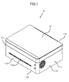
- FIG. 1 is a perspective view of an image formation device 10.
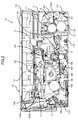
- FIG. 2 illustrates the internal structure of the image formation device 10.
- the image formation device 10 may be connected to an upper-stream device which is not shown in the drawing so as to receive an electrical signal of image data sent from the upper-stream device.
- the image formation device 10 may be a miniature multifunction printer, i.e., an ultra-thin multifunction printer.
- the image formation device 10 includes a frame body 11, an upper cover part 12, a scan unit 13, a paper feed unit 14, an exposure mechanism 15, an image formation unit 16, a fixing unit 17, and a paper discharge unit 18.
- the frame body 11 has a cuboid shape, and includes a left side plate 111, a right side plate 112, a front side plate 113, a rear side plate 114, and a bottom plate 115.
- a paper outlet 113a is formed on the front side plate 113.
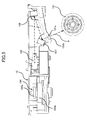
- FIG. 3 illustrates the internal structure of the image formation device 10 when its upper cover part 12 is opened.
- the upper cover part 12 is mounted on the rear side plate 114, and contains a cover main body 122, a pivot 123, and an upper cover plate 124.
- the cover main body 122 is installed on the rear side plate 114 by using the pivot 123, and may be rotatably opened or closed with respect to the frame body 11.
- the upper cover plate 124 is installed on the left end of the cover main body 122 by using a rotation shaft which is not presented in the drawings, and may be rotatably opened or closed with respect to the cover main body 122.
- the scan unit 13 which is used for scanning a document (not presented in the drawings) so as to generate image data, is disposed inside the cover main body 122, and is located under the upper cover plate 124.
- the user may open the upper cover plate 14 so as to put the document on the scan region of the scan unit 13, and then close the upper cover plate 124. After that, it is possible to scan the document.
- the paper feed unit 14 may supply a recording medium (e.g., a sheet of paper), which is not presented in the drawings, to the image formation unit 16.
- the paper feed unit 14 includes a paper inlet (not presented in the drawings), a paper feed tray 141, a paper separation member 142, and a paper feed roller 143.
- the paper inlet is used to let the recording medium enter the frame body 11 from the outside.
- the paper feed tray 141 is used for stacking, for example, plural sheets of paper thereon, and is disposed between the paper inlet and the bottom 115.
- the paper separation member 142 is mounted on the bottom plate 115, and is located near the bottom of the paper feed tray 141.
- the paper separation member 142 is used to separate the plural sheets of paper stacked on the paper feed tray 141, and then to supply the separated sheets of paper to the paper feed roller 143.
- the paper feed roller 143 is set above the paper separation member 142, and is used to transport the separated sheets of paper to the image formation unit 16.
- FIG. 4 illustrate the structure of an exposure mechanism 15 in the image formation device 10.
- the exposure mechanism 15 may be detachably installed on the lower surface of the cover main body 122.
- the exposure mechanism 15 is used to generate, on the basis of the image data sent from the upstream device or transmitted from the scan unit 13, an exposure signal, and then to send the exposure signal to the image formation unit 16.
- the exposure mechanism 15 has an installation tray 151 and an exposure unit 152.
- the installation tray 151 is mounted on the lower surface of the cover main body 122, and is used for supporting and securing the exposure unit 152.
- the installation tray 151 has a tray main body 151a and four installation members 151b. At the surrounding area of the tray main body 151 a, four installation holes are provided which are hidden by the installation members 151b.
- the four installation members 151 enters the cover main body 122 through the four installation holes, and are fixedly connected to the cover main body 122. In this way, the tray main body 151a may be mounted on the lower surface of the cover main body 122.
- each of the four installation members 151b may be a spring bolt.
- the exposure unit 152 is disposed in the installation tray 151, and is installed on the cover main body 122 so as to generate the exposure signal.
- the exposure unit 152 has a laser beam emitter 153, a rotation polygon mirror part 154, an f-theta lens 155, and two reflectors 156 and 157.
- the laser beam emitter 153 is secured at the right portion of the cover main body 122, and is used to emit a laser beam corresponding to the exposure signal.
- the rotation polygon mirror part 154 is secured at the central portion of the cover main body 122, and includes a rotation polygon mirror 154a and a drive motor 154b.
- the rotation polygon mirror 154a is used to receive the laser beam sent from the laser beam emitter 153, and to deviate the laser beam so as to let the laser beam arrive at a predetermined position on the f-theta lens 155.
- the drive motor 154b is connected to the rotation polygon mirror 154a, and is used to drive the rotation polygon mirror 154a so as to let it rotate according to a predetermined velocity.
- the f-theta lens 155 is used to receive the deviated laser beam, and then to generate a focused laser beam for emission.
- FIG. 5 illustrates the positional relationship between the exposure mechanism 15 and a photoconductor drum 161 in the image formation device 10.
- the two reflectors 156 and 157 (hereinafter, also called a “first reflector 156" and a “second reflector 157”) are sequentially disposed on a predetermined optical path P whose start point is the f-theta lens 155 and whose end point is the surface of the photoconductor drum 161 in the image formation unit 16, and are sequentially arranged along the predetermined optical path P according to a predetermined separation distance I 1 .
- the first and second reflectors 156 and 157 are used to receive the focused laser beam, and to reflect the focused laser beam plural times along the predetermined optical path P so as to let the focused laser beam arrive at the surface of the photoconductor drum 161.
- the first reflector 156 is located between the f-theta lens 155 and the second reflector 157 to serve as a forefront reflector for receiving the focused laser beam emitted from the f-theta lens 155, and reflects the focused laser beam to the second reflector 157.
- the second reflector 157 is located between the photoconductor drum 161 and the first reflector 156 to serve as an end reflector for reflecting the focused laser beam from the first reflector 156 to a predetermined position on the surface of the photoconductor drum 161.
- a loophole 151a is disposed on the installation tray 151, and is covered by a transparent glass plate 151b.
- the focused laser beam reflected from the second reflector 157 may arrive at the surface of the photoconductor drum 161 through the loophole 151a, and suspended substance such as toner and so on may not enter the exposure mechanism 15 due to the blocking of the transparent glass plate 151b.
- the distance between the first reflector 156 and the rotation polygon mirror 154a is D f
- the distance between the first reflector 156 and the second reflector 157 is I 1
- the distance from the second reflector 157 to the surface of the photoconductor drum 161 is D e
- D e is less than both I 1 and D f .
- D f is 45.5 mm
- I 1 is 31.3 mm
- D e is 30.5 mm, namely, D e ⁇ I 1 ⁇ D f .
- the image formation unit 16 is located below the exposure unit 15, and is used for receiving an exposure signal from the exposure unit 15 so as to form a toner image on a recording medium.
- the image formation unit 16 contains the photoconductor drum 161, a charged roller 162, at least one toner cartridge 163, a development roller 164, and a transfer roller 165.
- the charged roller 162 is used to supply electricity to the photoconductor drum 161 so as to let its surface be uniformly charged.
- the charged photoconductor drum 161 may generate an electrostatic latent image on its surface by receiving the focused laser beam.
- the at least one toner cartridge 163 is used to accommodate toner.
- the development roller 164 is used to supply the toner in the at least one toner cartridge 163 to the photoconductor drum 161 so as to carry out development with respect to the electrostatic latent image.
- the transfer roller 165 is used to transfer the toner image on the surface of the photoconductor drum 161 onto the recording medium.
- the photoconductor drum 161 and the transfer roller 165 are disposed facing each other, and the recording medium may be put between the photoconductor drum 161 and the transfer roller 165 so as to be transported to the fixing unit 17.
- the photoconductor drum 161, the charged roller 162, the at least one toner cartridge 163, and the development roller 164 in the image formation unit 16 may be integrated as an all-in-one (AIO) assembly which is detachable.
- AIO all-in-one
- the fixing unit 17 is located on the right portion of the image formation unit 16, and is used to heat and fix the toner image on the recording medium so as to finish image formation.
- the fixing unit 17 includes a fixing roller 171, a heat source (not presented in the drawings), and a pressure roller 172 for fixing.
- the fixing roller 171 is used for conducting fixing with respect to the toner image on the recording medium.
- the heat source is disposed inside the fixing roller 171, and serves as a heating means for providing heat to the fixing roller 171.
- the pressure roller 172 is used for applying pressure to the fixing roller 171.
- the fixing roller 171 and the pressure roller 172 are disposed facing each other so as to be able to fix the toner image on the recording medium which is located between the two, and the recording medium after the toner image thereon is fixed may be transported by the two.
- the paper discharge unit 18 contains a transport roller 181 and a pressure roller 182 for paper discharge.
- the recording medium after the toner image thereon is fixed may be put between the transport roller 181 and the pressure roller 182 so as to be transported by the two to the paper outlet 113a for paper discharge.
- a paper transport path S indicated by a dotted line therein is generated from the surface of the paper feed tray 141, between the paper separation member 142 and the paper feed roller 143, between the photoconductor drum 161 and the transfer roller 164, between the fixing roller 171 and the pressure roller 172, between the transport roller 181 and the pressure roller 182, and to the paper outlet 113a.
- the recording medium may be transported along the paper transport path S on which image formation is finished between the fixing roller 171 and the pressure roller 172.
- a recording medium stacked on the paper feed tray 141 is pushed along the paper transport path S as so to touch the paper feed roller 143, and enters between the paper feed roller 143 and the paper separation member 142 as the paper feed roller 143 rotates.
- the recording medium is transported by the paper feed roller 143 to the exposure unit 25.
- the exposure unit 25 generates an exposure signal on the basis of image data sent by the upstream device or transmitted from the scan unit 13, and a laser beam corresponding to the exposure signal is emitted by the laser beam emitter 153.
- the rotation polygon mirror 154a receives and deviates the laser beam so as to let the laser beam arrive at a predetermined position on the f-theta lens 155.
- the f-theta lens 155 receives the deviated laser beam so as to generate and emit a focused laser beam.
- the first reflector 156 receives the focused laser beam and reflects the focused laser beam to the second reflector 157.
- the second reflector 157 reflects the focused laser beam to a predetermined position on the surface of the photoconductor drum 161.
- the photoconductor drum 161 receives the focused laser beam, and generates an electrostatic latent image on its surface. Then the development roller 164 provides the toner in the at least one toner cartridge 163 to the photoconductor drum 161 so that a toner image corresponding to the electrostatic latent image may be formed on the surface of the photoconductor drum 161. And then, the transfer roller 165 transfers the toner image on the surface of the photoconductor drum 161 onto the recording medium which is located between the transfer roller 165 and the photoconductor drum 161, and at the same time, the recording medium is transported to the fixing unit 17 by the transfer roller 165 and the photoconductor drum 161 along the paper transport path S.
- the heat source inside the fixing unit 17 provides heat to the fixing roller 171, and the fixing roller 171 and the pressure roller 172 heat and pressurize the recording medium onto which the toner image on the surface of the photoconductor drum 161 has been transferred, so as to finish image formation. And then, the recording medium, which is located between the fixing roller 171 and the pressure roller 172, is transported to the transport roller 181 and the pressure roller 182 for paper discharge.
- transport roller 181 and the pressure roller 182 transport the recording medium, which is located between the two, to the paper outlet 113a so as to finish a print process.
- the distance D e from the second reflector 157 to the surface of the photoconductor drum 161 is not only less than the distance D f from the first reflector 156 to the rotation polygon mirror 154a but also less than the separation distance I 1 between the first reflector 156 and the second reflector 157; that is, the distance D e from the second reflector 157 to the surface of the photoconductor drum 161 is the smallest one.
- the position of the exposure mechanism 152 after it is reinstalled on the upper cover part 12 has an offset, it is also possible to restrain the occurrence of a deviation of the predetermined optical path P.
- the focused beam may arrive at the predetermined position on the surface of the photoconductor drum 161 as accurately as possible, so as to improve the uniformity of the electrostatic latent image generated on the surface of the photoconductor drum 161, thereby being able to guarantee the quality of the formed image.
- the distance D f between the first reflector 156 and the rotation polygon mirror 154a, the separation distance I 1 between the first reflector 156 and the second reflector 157, and the distance D e between the second reflector 157 and the surface of the photoconductor drum 161 may satisfy D f > I 1 > D e .
- the distance D f between the first reflector 156 and the rotation polygon mirror 154a, the separation distance I 1 between the first reflector 156 and the second reflector 157, and the distance D e between the second reflector 157 and the photoconductor drum 161 may be 45.5 mm, 31.3 mm and 30.5 mm, respectively.
- the position of the AIO assembly i.e., the photoconductor drum 161, the charged roller 162, the at least one toner cartridge 163, and the development roller 164 in the image formation unit 16
- the AIO assembly is disposed at a position whose height is different from the heights of the positions of the rotation polygon mirror 154a and the drive motor 154b.
- the position of the image formation unit 16 is not located on the rotation axis of the rotation polygon mirror 154a. As a result, it is also possible to reduce the height of the image formation device 10.
- the drive motor 154b is disposed far away from the fixing unit 17 containing the heat resource, so that the thermal deformation of the rotation polygon mirror 154b and so on may be restrained. As a result, it is possible to improve the accuracy of the predetermined optical path P so as to obtain an image having good quality.
- the exposure unit, the exposure mechanism, and the image formation device are not limited to the above-described structures.
- the image formation device 10 contains the scan unit 13; that is, the image formation device 10 is a kind of multi-functional printer. However, the image formation device 10 may also not contain the scan unit 13.
- the distance D e between the second reflector 157 and the surface of the photoconductor drum 161, the separation distance I 1 between the first reflector 156 and the second reflector 157, and the distance D f between the first reflector 156 and the rotation polygon mirror 154a meet D e ⁇ I 1 ⁇ D f .
- the present disclosure is not limited to this. As long as D e is the smallest one among the three, the three may satisfy another relationship.
- the distance D f between the first reflector 156 and the rotation polygon mirror 154a, the separation distance I 1 between the first reflector 156 and the second reflector 157, and the distance D e between the second reflector 157 and the surface of the photoconductor drum 161 may be 45.5 mm, 31.3 mm, and 30.5 mm, respectively.
- the present disclosure is not limited to this. As long as D e is the smallest one among the three, the three may take other values.
- the present disclosure is not limited to this. That is, more than two reflectors may be installed in the image formation device 10.
- the number of reflectors may be N which is an integer greater or equal to two.
- the N reflectors are sequentially arranged along the predetermined optical path P and are sequentially called a "first reflector", a "second reflector”, ..., and an "N-th reflector".
- the distance between the first reflector and the second reflector is called a "first predetermined separation distance I 1 "
- the distance between the second reflector and the third reflector is called a “second predetermined separation distance I 2 "
- the distance between the (N-1)-th reflector and the N-th reflector is called an "(N-1)-th separation distance I N-1 ".
- the first reflector serves as a forefront reflector, and the distance from the forefront reflector to the rotation polygon mirror 154a is D f .
- the N-th reflector serves as an end reflector, and the distance between the end reflector and the surface of the photoconductor drum 161 is D e .
- D e be the smallest one among D f , D e , I 1 , I 2 , ..., and I N-1 .
- the laser beam emitter 153 emits only one laser beam.
- the present disclosure is not limited to this. That is, the laser beam emitter 153 may also emits two or more laser beams. In this way, it is possible to reduce the rotation velocity of the drive motor 154b so as to restrain the temperature increase of the exposure unit 152. As a result, it is possible to avoid the thermal deformation of the polygon mirror 154a and so forth, so as to be able to improve the accuracy of the predetermined optical path P.
Landscapes
- Physics & Mathematics (AREA)
- General Physics & Mathematics (AREA)
- Optics & Photonics (AREA)
- Electrophotography Configuration And Component (AREA)
- Facsimile Scanning Arrangements (AREA)
- Exposure Or Original Feeding In Electrophotography (AREA)
Abstract
Description
- The present disclosure relates to an exposure unit as well as an exposure mechanism and image formation device including the exposure unit.
- Up to now, an image formation device such as a printer or a copier has been widely used in offices, etc. In general, this kind of image formation device contains an exposure unit and an image formation unit. The exposure unit gives an exposure signal generated on the basis of image data to the image formation unit. And then, the image formation unit forms an image on a recording medium (e.g., a sheet of paper) on the grounds of the exposure signal.
- The image formation unit is usually provided below the exposure unit, and generally includes an integrated assembly consisting of a photoconductor drum, at least one toner cartridge, etc. This kind of integrated assembly is an easily-consumed product, so it needs to be replaced periodically.
- The exposure unit is generally secured to the upper cover part of the image formation device. The reason is that on the one hand, the laser beam from the exposure unit may be in a stable state, and on the other hand, once the upper cover part is opened, the exposure unit may depart from the image formation unit together with the upper cover part so that it is easy to take out and replace the integrated assembly by a user.
- However, since the exposure unit is located above the image formation unit, the space for replacing the integrated assembly is still relatively small. That is, it is still relatively difficult to replace the integrated assembly. As a result, when replacing the integrated assembly, it is necessary to first demount the exposure unit, thereby resulting in wasting time and energy so as to bring inconvenience for the user.
- In order to solve the above-mentioned problem of inconvenience, the exposure unit may be detachably mounted on the upper cover part. When the user wants to take out the exposure unit for replacement or due to a paper jam, he/she only needs to open the upper cover part. In this way, it is very easy to demount the exposure unit. This kind of image formation device is disclosed in Japan Patent Application Publication No.
2008-096957 - However, in this kind of image formation device, just because the exposure unit needs to be easily demounted, an installation clearance must be exist between the exposure unit and the upper cover part. Due to this, the position of the exposure unit after reinstallation may have an offset, so that the laser beam from the exposure unit may deviate from a predetermined optical path and may not arrive at a predetermined position on the surface of the photoconductor drum. As a result, the electrostatic latent image generated on the photoconductor drum is obviously nonuniform, thereby resulting in dramatically reducing the quality of the formed image.
- Therefore, it is necessary to provide an exposure unit as well as an exposure mechanism and image formation device containing the exposure unit whose position may not have an offset after reinstallation, so that it is possible to ensure that the laser beam from the exposure unit may not deviate from the predetermined optical path. In this way, it is possible to guarantee the quality of the formed image.
- According to a first aspect of the present disclosure, an exposure unit is provided which may generate an exposure signal on the basis of image data. The exposure unit is disposed inside an image formation device including a frame body and an upper cover part. The frame body accommodates an image formation unit for forming an image on the grounds of the exposure signal. The upper cover part may be rotatably opened and closed with respect to the frame body. The exposure unit is installed on the lower surface of the upper cover part. The exposure unit may include:
- a laser beam emitter for emitting a laser beam corresponding to the exposure signal;
- a rotation polygon mirror part including a rotation polygon mirror for receiving and deviating the laser beam;
- an f-theta lens for receiving the deviated laser beam and generating a focused beam for emission; and
- plural reflectors sequentially disposed on a predetermined optical path whose start point is the f-theta lens and whose end point is the surface of a photoconductor drum in the image formation unit, and sequentially arranged according to predetermined separation distances for receiving the focused beam and reflecting the focused beam plural times along the predetermined optical path so as to cause the focused beam to arrive at the surface of the photoconductor drum.
- The plural reflectors include a forefront reflector and an end reflector. The forefront reflector is used for receiving the focused beam, and the end reflector is used for reflecting the focused beam to the surface of the photoconductor.
- The distance from the end reflector to the surface of the photoconductor drum is less than both the predetermined separation distances and the distance from the forefront reflector to the rotation polygon mirror.
- According to a second aspect of the present disclosure, an exposure mechanism is provided which may generate an exposure signal on the basis of image data. The exposure mechanism is disposed inside an image formation device including a frame body and an upper cover part. The frame body accommodates an image formation unit for forming an image on the grounds of the exposure signal. The upper cover part may be rotatably opened and closed with respect to the frame body. The exposure mechanism may include an installation tray which is mounted on the lower surface of the upper cover part and an exposure unit which is disposed in the installation tray for generating the exposure signal. The exposure unit may be one according to the first aspect of the present disclosure.
- According to a third aspect of the present disclosure, an image formation image is provided which may include:
- a frame body;
- an upper cover part which is mounted on the frame body and may be rotatably opened and closed with respect to the frame body;
- an exposure mechanism which is installed on the lower surface of the upper cover part and is used for generating an exposure signal on the basis of image data; and
- an image formation unit which is accommodated inside the frame body and is used for generating a toner image on a recording medium on the grounds of the exposure signal so as to carry out an image formation process.
- The exposure mechanism may be one according to the second aspect of the present disclosure.
- As a result, by utilizing the above-described exposure unit, exposure mechanism, and image formation device, since the distance between the end reflector and the surface of the photoconductor drum is less than the separation distance between any two adjacent reflectors as well as the distance between the forefront reflector and the rotation polygon mirror (i.e., the distance from the end reflector to the surface of the photoconductor drum is the smallest one), although the position of the exposure mechanism after it is reinstalled on the upper cover part has an offset, it is also possible to restrain the occurrence of a deviation of the predetermined optical path. In this way, the focused beam may arrive at the predetermined position on the surface of the photoconductor drum as accurately as possible so as to effectively improve the uniformity of the electrostatic latent image generated, thereby being able to guarantee the quality of the formed image.
-
-
FIG. 1 is a perspective view of an image formation device; -
FIG. 2 illustrates the internal structure of the image formation device; -
FIG. 3 illustrates the internal structure of the image formation device when its upper cover part is opened; -
FIG. 4 illustrate a structure of an exposure mechanism in the image formation device; and -
FIG. 5 illustrates the positional relationship between the exposure mechanism and a photoconductor drum in the image formation device. - In order to let those people skilled in the art better understand the present disclosure, hereinafter, the embodiments of the present disclosure will be concretely described with reference to the drawings. However it should be noted that the same symbols, which are in the specification and the drawings, stand for the constructional elements having basically the same function and structure, and the repeated explanations for the constructional elements are omitted.
- According to a first aspect of the present disclosure, an exposure unit is provided which may generate an exposure signal on the grounds of image data. The exposure unit is disposed inside an image formation device including a frame body and an upper cover part, and is installed on the lower surface of the upper cover part. The frame body accommodates an image formation unit which is used for forming an image on a recording medium (e.g., a sheet of paper) on the basis of the exposure signal. The upper cover part may be rotatably opened and closed with respect to the frame body.
- The exposure unit may include a laser beam emitter, a rotation polygon mirror part, an f-theta lens, and plural reflectors. The laser beam emitter is used for emitting a laser beam corresponding to the exposure signal. The rotation polygon mirror part includes a rotation polygon mirror, and is used for receiving and deviating the laser beam. The f-theta lens is used for receiving the deviated laser beam and generating a focused beam for emission. The plural reflectors are sequentially disposed on a predetermined optical path whose start point is the f-theta lens and whose end point is the surface of a photoconductor drum of the image formation unit, and are sequentially arranged according to predetermined separation distances for receiving the focused beam and reflecting the focused beam plural times along the predetermined optical path so as to cause the focused beam to arrive at the surface of the photoconductor drum.
- The plural reflectors may include a forefront reflector and an end reflector. The forefront reflector is used for receiving the focused beam, and the end reflector is used for reflecting the focused beam to the surface of the photoconductor drum. The distance from the end reflector to the surface of the photoconductor drum is less than both the predetermined separation distances and the distance from the forefront reflector to the rotation polygon mirror.
- In particular, the plural reflectors may include N reflectors. Here N is an integer which is greater than or equal to two. The N reflectors are sequentially arranged along the predetermined optical path, and are sequentially called a "first reflector", a "second reflector", ..., and an "N-th reflector". The distance between the first reflector and the second reflector is called a "first predetermined separation distance I1", the distance between the second reflector and the third reflector is called a "second predetermined separation distance I2", ..., and the distance between the (N-1)-th reflector and the N-th reflector is called an "(N-1)-th predetermined separation distance IN-1". The first reflector serves as the forefront reflector, and the distance from the forefront reflector to the rotation polygon mirror is Df. The N-th reflector serves as the end reflector, and the distance between the end reflector and the surface of the photoconductor drum is De. Here, Df and De as well as I1, I2, ..., and IN-1 satisfy the following condition, namely, De < IN-1 < ... I2 < I1 < Df.
- Moreover, the plural reflectors may also include two reflectors called a "first reflector" and a "second reflector", respectively. The distance between the first reflector and the second reflector is I1. The first reflector serves as the forefront reflector, and the distance from the forefront reflector to the rotation polygon mirror is Df. The second reflector serves as the end reflector, and the distance between the end reflector and the surface of the photoconductor drum is De. Here, Df : I1 : De = 44-47 : 31-33 : 28-30. Preferably, Df : I1 : De = 45.5 : 31.3 : 30.5.
- Furthermore, the distance De between the end reflector and the surface of the photoconductor drum is 30.5 mm.
- In addition, the laser beam emitter may also emit two or more laser beams.
- According to a second aspect of the present disclosure, an exposure mechanism is provided which may generate an exposure signal on the basis of image data. The exposure mechanism is disposed inside an image formation device having a frame body and an upper cover part. The frame body accommodates an image formation unit which is used for forming an image on a recording medium such as a sheet of paper and so forth on the grounds of the exposure signal. The upper cover part may be rotatably opened and closed with respect to the frame body.
- The exposure mechanism may include an installation tray and an exposure unit. The installation tray is mounted on the lower surface of the upper cover part, and the exposure unit is disposed in the installation tray for generating the exposure signal. The exposure unit may be one according to the first aspect of the present disclosure.
- According to a third aspect of the present disclosure, an image formation device is provided which may include a frame body, an upper cover part, an exposure mechanism, and an image formation unit. The upper cover part is installed on the frame body, and may be rotatably opened and closed with respect to the frame body. The exposure mechanism is mounted on the lower surface of the upper cover part, and is used for generating an exposure signal on the basis of image data. The image formation unit is accommodated inside the frame body, and is used for generating a toner image on a recording medium such as a sheet of paper and so forth on the grounds of the exposure signal so as to carry out an image formation process. The exposure mechanism may be one according to the second aspect of the present disclosure.
- Furthermore, the image formation device may further include a scan unit which is disposed in the upper cover part and is used for scanning a document so as to generate the image data.
- Moreover, the image formation device may further include a fixing unit and a drive motor. The fixing unit is used for heating and fixing the toner image generated on the recording medium so as to finish the image formation process. The drive motor is connected to a rotation polygon mirror which is included in a rotation polygon mirror part, so as to drive the rotation polygon mirror to rotate for receiving and deviating a laser beam. Here, the drive motor is provided at a position far away from the fixing unit.
-
FIG. 1 is a perspective view of animage formation device 10. -
FIG. 2 illustrates the internal structure of theimage formation device 10. - The
image formation device 10 may be connected to an upper-stream device which is not shown in the drawing so as to receive an electrical signal of image data sent from the upper-stream device. In one embodiment, theimage formation device 10 may be a miniature multifunction printer, i.e., an ultra-thin multifunction printer. - As presented in
FIGS. 1 and2 , theimage formation device 10 includes aframe body 11, anupper cover part 12, ascan unit 13, apaper feed unit 14, anexposure mechanism 15, animage formation unit 16, a fixingunit 17, and apaper discharge unit 18. - The
frame body 11 has a cuboid shape, and includes aleft side plate 111, aright side plate 112, afront side plate 113, arear side plate 114, and abottom plate 115. Apaper outlet 113a is formed on thefront side plate 113. -
FIG. 3 illustrates the internal structure of theimage formation device 10 when itsupper cover part 12 is opened. - As presented in
FIGS. 1 to 3 , theupper cover part 12 is mounted on therear side plate 114, and contains a covermain body 122, apivot 123, and anupper cover plate 124. - The cover
main body 122 is installed on therear side plate 114 by using thepivot 123, and may be rotatably opened or closed with respect to theframe body 11. - The
upper cover plate 124 is installed on the left end of the covermain body 122 by using a rotation shaft which is not presented in the drawings, and may be rotatably opened or closed with respect to the covermain body 122. - The
scan unit 13, which is used for scanning a document (not presented in the drawings) so as to generate image data, is disposed inside the covermain body 122, and is located under theupper cover plate 124. When it is necessary to conduct a scan process, the user may open theupper cover plate 14 so as to put the document on the scan region of thescan unit 13, and then close theupper cover plate 124. After that, it is possible to scan the document. - The
paper feed unit 14 may supply a recording medium (e.g., a sheet of paper), which is not presented in the drawings, to theimage formation unit 16. Thepaper feed unit 14 includes a paper inlet (not presented in the drawings), apaper feed tray 141, apaper separation member 142, and apaper feed roller 143. - The paper inlet is used to let the recording medium enter the
frame body 11 from the outside. - The
paper feed tray 141 is used for stacking, for example, plural sheets of paper thereon, and is disposed between the paper inlet and the bottom 115. - The
paper separation member 142 is mounted on thebottom plate 115, and is located near the bottom of thepaper feed tray 141. Thepaper separation member 142 is used to separate the plural sheets of paper stacked on thepaper feed tray 141, and then to supply the separated sheets of paper to thepaper feed roller 143. - The
paper feed roller 143 is set above thepaper separation member 142, and is used to transport the separated sheets of paper to theimage formation unit 16. -
FIG. 4 illustrate the structure of anexposure mechanism 15 in theimage formation device 10. - As presented in
FIGS. 2 to 4 , theexposure mechanism 15 may be detachably installed on the lower surface of the covermain body 122. Theexposure mechanism 15 is used to generate, on the basis of the image data sent from the upstream device or transmitted from thescan unit 13, an exposure signal, and then to send the exposure signal to theimage formation unit 16. Theexposure mechanism 15 has aninstallation tray 151 and anexposure unit 152. - The
installation tray 151 is mounted on the lower surface of the covermain body 122, and is used for supporting and securing theexposure unit 152. Theinstallation tray 151 has a traymain body 151a and fourinstallation members 151b. At the surrounding area of the traymain body 151 a, four installation holes are provided which are hidden by theinstallation members 151b. The fourinstallation members 151 enters the covermain body 122 through the four installation holes, and are fixedly connected to the covermain body 122. In this way, the traymain body 151a may be mounted on the lower surface of the covermain body 122. In one embodiment, each of the fourinstallation members 151b may be a spring bolt. - The
exposure unit 152 is disposed in theinstallation tray 151, and is installed on the covermain body 122 so as to generate the exposure signal. Theexposure unit 152 has alaser beam emitter 153, a rotationpolygon mirror part 154, an f-theta lens 155, and tworeflectors - The
laser beam emitter 153 is secured at the right portion of the covermain body 122, and is used to emit a laser beam corresponding to the exposure signal. - The rotation
polygon mirror part 154 is secured at the central portion of the covermain body 122, and includes arotation polygon mirror 154a and adrive motor 154b. Therotation polygon mirror 154a is used to receive the laser beam sent from thelaser beam emitter 153, and to deviate the laser beam so as to let the laser beam arrive at a predetermined position on the f-theta lens 155. Thedrive motor 154b is connected to therotation polygon mirror 154a, and is used to drive therotation polygon mirror 154a so as to let it rotate according to a predetermined velocity. - The f-
theta lens 155 is used to receive the deviated laser beam, and then to generate a focused laser beam for emission. -
FIG. 5 illustrates the positional relationship between theexposure mechanism 15 and aphotoconductor drum 161 in theimage formation device 10. - As presented in
FIGS. 4 and5 , the tworeflectors 156 and 157 (hereinafter, also called a "first reflector 156" and a "second reflector 157") are sequentially disposed on a predetermined optical path P whose start point is the f-theta lens 155 and whose end point is the surface of thephotoconductor drum 161 in theimage formation unit 16, and are sequentially arranged along the predetermined optical path P according to a predetermined separation distance I1. The first andsecond reflectors photoconductor drum 161. - In particular, the
first reflector 156 is located between the f-theta lens 155 and thesecond reflector 157 to serve as a forefront reflector for receiving the focused laser beam emitted from the f-theta lens 155, and reflects the focused laser beam to thesecond reflector 157. Thesecond reflector 157 is located between thephotoconductor drum 161 and thefirst reflector 156 to serve as an end reflector for reflecting the focused laser beam from thefirst reflector 156 to a predetermined position on the surface of thephotoconductor drum 161. - In addition, a
loophole 151a is disposed on theinstallation tray 151, and is covered by atransparent glass plate 151b. In this way, the focused laser beam reflected from thesecond reflector 157 may arrive at the surface of thephotoconductor drum 161 through theloophole 151a, and suspended substance such as toner and so on may not enter theexposure mechanism 15 due to the blocking of thetransparent glass plate 151b. - The distance between the
first reflector 156 and therotation polygon mirror 154a is Df, and the distance between thefirst reflector 156 and thesecond reflector 157 is I1. The distance from thesecond reflector 157 to the surface of thephotoconductor drum 161 is De, and De is less than both I1 and Df. In one embodiment, Df is 45.5 mm, I1 is 31.3 mm, and De is 30.5 mm, namely, De < I1 < Df. - As presented in
FIGS. 2 and3 , theimage formation unit 16 is located below theexposure unit 15, and is used for receiving an exposure signal from theexposure unit 15 so as to form a toner image on a recording medium. Theimage formation unit 16 contains thephotoconductor drum 161, a chargedroller 162, at least onetoner cartridge 163, adevelopment roller 164, and atransfer roller 165. The chargedroller 162 is used to supply electricity to thephotoconductor drum 161 so as to let its surface be uniformly charged. The chargedphotoconductor drum 161 may generate an electrostatic latent image on its surface by receiving the focused laser beam. The at least onetoner cartridge 163 is used to accommodate toner. Thedevelopment roller 164 is used to supply the toner in the at least onetoner cartridge 163 to thephotoconductor drum 161 so as to carry out development with respect to the electrostatic latent image. Thetransfer roller 165 is used to transfer the toner image on the surface of thephotoconductor drum 161 onto the recording medium. Thephotoconductor drum 161 and thetransfer roller 165 are disposed facing each other, and the recording medium may be put between thephotoconductor drum 161 and thetransfer roller 165 so as to be transported to the fixingunit 17. - In one embodiment, the
photoconductor drum 161, the chargedroller 162, the at least onetoner cartridge 163, and thedevelopment roller 164 in theimage formation unit 16 may be integrated as an all-in-one (AIO) assembly which is detachable. In this way, as presented inFIG. 3 , after theupper cover part 12 is opened, theexposure mechanism 15 departs from theimage formation unit 16 so that it is easy for the user to exchange, for example, theimage formation unit 16. - The fixing
unit 17 is located on the right portion of theimage formation unit 16, and is used to heat and fix the toner image on the recording medium so as to finish image formation. The fixingunit 17 includes a fixingroller 171, a heat source (not presented in the drawings), and apressure roller 172 for fixing. The fixingroller 171 is used for conducting fixing with respect to the toner image on the recording medium. The heat source is disposed inside the fixingroller 171, and serves as a heating means for providing heat to the fixingroller 171. Thepressure roller 172 is used for applying pressure to the fixingroller 171. The fixingroller 171 and thepressure roller 172 are disposed facing each other so as to be able to fix the toner image on the recording medium which is located between the two, and the recording medium after the toner image thereon is fixed may be transported by the two. - The
paper discharge unit 18 contains atransport roller 181 and apressure roller 182 for paper discharge. The recording medium after the toner image thereon is fixed may be put between thetransport roller 181 and thepressure roller 182 so as to be transported by the two to thepaper outlet 113a for paper discharge. - From the above description, it may be understood that as presented in
FIGS. 2 and3 , a paper transport path S indicated by a dotted line therein is generated from the surface of thepaper feed tray 141, between thepaper separation member 142 and thepaper feed roller 143, between thephotoconductor drum 161 and thetransfer roller 164, between the fixingroller 171 and thepressure roller 172, between thetransport roller 181 and thepressure roller 182, and to thepaper outlet 113a. The recording medium may be transported along the paper transport path S on which image formation is finished between the fixingroller 171 and thepressure roller 172. - In particular, in the
image formation device 10, as presented inFIGS. 2 and3 , first a recording medium stacked on thepaper feed tray 141 is pushed along the paper transport path S as so to touch thepaper feed roller 143, and enters between thepaper feed roller 143 and thepaper separation member 142 as thepaper feed roller 143 rotates. - And then, the recording medium is transported by the
paper feed roller 143 to the exposure unit 25. - At this time, the exposure unit 25 generates an exposure signal on the basis of image data sent by the upstream device or transmitted from the
scan unit 13, and a laser beam corresponding to the exposure signal is emitted by thelaser beam emitter 153. Therotation polygon mirror 154a receives and deviates the laser beam so as to let the laser beam arrive at a predetermined position on the f-theta lens 155. The f-theta lens 155 receives the deviated laser beam so as to generate and emit a focused laser beam. Thefirst reflector 156 receives the focused laser beam and reflects the focused laser beam to thesecond reflector 157. Thesecond reflector 157 reflects the focused laser beam to a predetermined position on the surface of thephotoconductor drum 161. - The
photoconductor drum 161 receives the focused laser beam, and generates an electrostatic latent image on its surface. Then thedevelopment roller 164 provides the toner in the at least onetoner cartridge 163 to thephotoconductor drum 161 so that a toner image corresponding to the electrostatic latent image may be formed on the surface of thephotoconductor drum 161. And then, thetransfer roller 165 transfers the toner image on the surface of thephotoconductor drum 161 onto the recording medium which is located between thetransfer roller 165 and thephotoconductor drum 161, and at the same time, the recording medium is transported to the fixingunit 17 by thetransfer roller 165 and thephotoconductor drum 161 along the paper transport path S. - After that, the heat source inside the fixing
unit 17 provides heat to the fixingroller 171, and the fixingroller 171 and thepressure roller 172 heat and pressurize the recording medium onto which the toner image on the surface of thephotoconductor drum 161 has been transferred, so as to finish image formation. And then, the recording medium, which is located between the fixingroller 171 and thepressure roller 172, is transported to thetransport roller 181 and thepressure roller 182 for paper discharge. - Finally the
transport roller 181 and thepressure roller 182 transport the recording medium, which is located between the two, to thepaper outlet 113a so as to finish a print process. - According to the
exposure unit 152, theexposure mechanism 15, and theimage formation device 10, the distance De from thesecond reflector 157 to the surface of thephotoconductor drum 161 is not only less than the distance Df from thefirst reflector 156 to therotation polygon mirror 154a but also less than the separation distance I1 between thefirst reflector 156 and thesecond reflector 157; that is, the distance De from thesecond reflector 157 to the surface of thephotoconductor drum 161 is the smallest one. As a result, although the position of theexposure mechanism 152 after it is reinstalled on theupper cover part 12 has an offset, it is also possible to restrain the occurrence of a deviation of the predetermined optical path P. In this way, the focused beam may arrive at the predetermined position on the surface of thephotoconductor drum 161 as accurately as possible, so as to improve the uniformity of the electrostatic latent image generated on the surface of thephotoconductor drum 161, thereby being able to guarantee the quality of the formed image. - Moreover, the distance Df between the
first reflector 156 and therotation polygon mirror 154a, the separation distance I1 between thefirst reflector 156 and thesecond reflector 157, and the distance De between thesecond reflector 157 and the surface of thephotoconductor drum 161 may satisfy Df > I1 > De. As a result, on the one hand, it is possible to further restrain the occurrence of a deviation of the predetermined optical path P so as to improve the uniformity of the electrostatic latent image generated on the surface of thephotoconductor drum 161, thereby being able to get an image having good quality; on the other hand, it is also possible to reduce the height of theexposure unit 152 so as to reduce the height of theimage formation device 10. - Furthermore, the distance Df between the
first reflector 156 and therotation polygon mirror 154a, the separation distance I1 between thefirst reflector 156 and thesecond reflector 157, and the distance De between thesecond reflector 157 and thephotoconductor drum 161 may be 45.5 mm, 31.3 mm and 30.5 mm, respectively. As a result, it is possible to further restrain the occurrence of a deviation of the predetermined optical path P so as to improve the uniformity of the electrostatic latent image generated on the surface of thephotoconductor drum 161, thereby being able to acquire an image having good quality. - Additionally, as presented in
FIG. 2 , the position of the AIO assembly (i.e., thephotoconductor drum 161, the chargedroller 162, the at least onetoner cartridge 163, and thedevelopment roller 164 in the image formation unit 16) is a little lower than the positions of therotation polygon mirror 154a and thedrive motor 154b; that is, the AIO assembly is disposed at a position whose height is different from the heights of the positions of therotation polygon mirror 154a and thedrive motor 154b. As a result, it is possible to reduce the height of theimage formation device 10. - Moreover, as presented in
FIG. 2 , the position of theimage formation unit 16 is not located on the rotation axis of therotation polygon mirror 154a. As a result, it is also possible to reduce the height of theimage formation device 10. - In addition, as presented in
FIG. 2 , thedrive motor 154b is disposed far away from the fixingunit 17 containing the heat resource, so that the thermal deformation of therotation polygon mirror 154b and so on may be restrained. As a result, it is possible to improve the accuracy of the predetermined optical path P so as to obtain an image having good quality. - Of course, the exposure unit, the exposure mechanism, and the image formation device according to the embodiments of the present disclosure are not limited to the above-described structures.
- Here it should be noted that the
image formation device 10 contains thescan unit 13; that is, theimage formation device 10 is a kind of multi-functional printer. However, theimage formation device 10 may also not contain thescan unit 13. - Moreover, as described above, in the
image formation device 10, the distance De between thesecond reflector 157 and the surface of thephotoconductor drum 161, the separation distance I1 between thefirst reflector 156 and thesecond reflector 157, and the distance Df between thefirst reflector 156 and therotation polygon mirror 154a meet De < I1 < Df. However, the present disclosure is not limited to this. As long as De is the smallest one among the three, the three may satisfy another relationship. - Furthermore, as described above, in the
image formation device 10, the distance Df between thefirst reflector 156 and therotation polygon mirror 154a, the separation distance I1 between thefirst reflector 156 and thesecond reflector 157, and the distance De between thesecond reflector 157 and the surface of thephotoconductor drum 161 may be 45.5 mm, 31.3 mm, and 30.5 mm, respectively. However, the present disclosure is not limited to this. As long as De is the smallest one among the three, the three may take other values. - Additionally, as described above, in the
image formation device 10, the distance Df between thefirst reflector 156 and therotation polygon mirror 154a, the separation distance I1 between thefirst reflector 156 and thesecond reflector 157, and the distance De between thesecond reflector 157 and the surface of thephotoconductor drum 161 may satisfy Df : I1 : De = 45.5 : 31.3 : 30.5. However, the present disclosure is not limited to this. As long as De is the smallest one among the three, the three may also take other values, for example, Df : I1 : De = 44-47 : 31-33 : 28-30. - Moreover, as described above, in the
image formation device 10, there are only two reflectors. However, the present disclosure is not limited to this. That is, more than two reflectors may be installed in theimage formation device 10. For example, the number of reflectors may be N which is an integer greater or equal to two. The N reflectors are sequentially arranged along the predetermined optical path P and are sequentially called a "first reflector", a "second reflector", ..., and an "N-th reflector". The distance between the first reflector and the second reflector is called a "first predetermined separation distance I1", the distance between the second reflector and the third reflector is called a "second predetermined separation distance I2", ..., and the distance between the (N-1)-th reflector and the N-th reflector is called an "(N-1)-th separation distance IN-1". The first reflector serves as a forefront reflector, and the distance from the forefront reflector to therotation polygon mirror 154a is Df. The N-th reflector serves as an end reflector, and the distance between the end reflector and the surface of thephotoconductor drum 161 is De. In this case, in order to achieve the purpose of restraining the occurrence of a deviation of the predetermined optical path P, it is necessary to let De be the smallest one among Df, De, I1, I2, ..., and IN-1. - In addition, as described above, in the
image formation device 10, thelaser beam emitter 153 emits only one laser beam. However, the present disclosure is not limited to this. That is, thelaser beam emitter 153 may also emits two or more laser beams. In this way, it is possible to reduce the rotation velocity of thedrive motor 154b so as to restrain the temperature increase of theexposure unit 152. As a result, it is possible to avoid the thermal deformation of thepolygon mirror 154a and so forth, so as to be able to improve the accuracy of the predetermined optical path P. - While the present disclosure is described with reference to the specific embodiments chosen for purpose of illustration, it should be apparent that the present disclosure is not limited to these embodiments, but numerous modifications could be made thereto by those people skilled in the art without departing from the basic concept and technical scope of the present disclosure.
- The present application is based on and claims the benefit of priority of Chinese Patent Application No.
201510673842.8 filed on Oct. 16, 2015
Claims (10)
- An exposer unit, which generates an exposure signal based on image data, is disposed inside an image formation device including a frame body accommodating an image formation unit for forming an image based on the exposure signal and an upper cover part able to be rotatably opened and closed with respect to the frame body, and is mounted on a lower surface of the upper cover part, comprising:a laser beam emitter for emitting a laser beam corresponding to the exposure signal;a rotation polygon mirror part including a rotation polygon mirror for receiving and deviating the laser beam;an f-theta lens for receiving the deviated laser beam and generating a focused beam for emission; andplural reflectors sequentially disposed on a predetermined optical path whose start point is the f-theta lens and whose end point is a surface of a photoconductor drum in the image formation unit, and sequentially arranged according to predetermined separation distances for receiving the focused beam and reflecting the focused beam plural times along the predetermined optical path so as to cause the focused beam to arrive at the surface of the photoconductor drum,wherein, the plural reflectors include a forefront reflector and an end reflector, the forefront reflector being used for receiving the focused beam, the end reflector being used for reflecting the focused beam to the surface of the photoconductor drum; anda distance from the end reflector to the surface of the photoconductor drum is less than both the predetermined separation distances and a distance from the forefront reflector to the rotation polygon mirror.
- The exposure unit according to claim 1, wherein,
the plural reflectors include N reflectors, N being an integer greater or equal to two;
the N reflectors are sequentially arranged along the predetermined optical path, and are sequentially called a "first reflector", a "second reflector", ..., and an "N-th reflector";
a distance between the first reflector and the second reflector is called a "first predetermined separation distance I1", a distance between the second reflector and the third reflector is called a "second predetermined separation distance I2", ..., and a distance between the (N-1)-th reflector and the N-th reflector is called an "(N-1)-th separation distance IN-1";
the first reflector serves as the forefront reflector, and a distance between the forefront reflector and the rotation polygon mirror is Df;
the N-th reflector serves as the end reflector, and a distance between the end reflector and the surface of the photoconductor drum is De; and
Df, De, I1, I2, ..., and IN-1 satisfy De < IN-1 < I2 < I1 < ... < Df. - The exposure unit according to claim 2, wherein,
the N reflectors include two reflectors called a "first reflector" and a "second reflector"; the first reflector is the forefront reflector, and the second reflector is the end reflector; and
Df : I1 : De = 44-47 : 31-33 : 28-30. - The exposure unit according to claim 3, wherein,
Df : I1 : De = 45.5 : 31.3 : 30.5. - The exposure unit according to claim 4, wherein,
De = 30.5 mm. - The exposure unit according to claim 4, wherein,
the laser beam emitter emits two laser beams. - An exposure mechanism, which generates an exposure signal based on image data and is disposed inside an image formation device including a frame body accommodating an image formation unit for forming an image based on the exposure signal and an upper cover part able to be rotatably opened and closed with respect to the frame body, comprising:an installation tray mounted on a lower surface of the upper cover part; andan exposure unit disposed in the installation tray for generating the exposure signal,wherein, the exposure unit is one according to any one of claims 1 to 6.
- An image formation device comprising:a frame body;an upper cover part which is installed on the frame body and may be rotatably opened and closed with respect to the frame body;an exposure mechanism which is mounted on a lower surface of the upper cover part and is used for generating an exposure signal based on image data; andan image formation unit which is accommodated inside the frame body and is used for generating a toner image on a recording medium based on the exposure signal so as to carry out an image formation process,wherein, the exposure mechanism is one according to claim 7.
- The image formation device according to claim 8, further comprising:a scan unit which is installed in the upper cover part and is used for scanning a document so as to generate the image data.
- The image formation device according to claim 8, further comprising:a fixing unit for heating and fixing the toner image on the recording medium so as to finish the image formation process,wherein, the rotation polygon mirror part includes a rotation polygon mirror for receiving and deviating the laser beam and a drive motor connected to the rotation polygon mirror so as to drive the rotation polygon mirror to let it rotate, andthe drive motor is disposed far away from the fixing unit.
Applications Claiming Priority (1)
| Application Number | Priority Date | Filing Date | Title |
|---|---|---|---|
| CN201510673842.8A CN106597819B (en) | 2015-10-16 | 2015-10-16 | Exposure unit, exposure mechanism, and image forming apparatus |
Publications (2)
| Publication Number | Publication Date |
|---|---|
| EP3156849A1 true EP3156849A1 (en) | 2017-04-19 |
| EP3156849B1 EP3156849B1 (en) | 2023-05-24 |
Family
ID=57018027
Family Applications (1)
| Application Number | Title | Priority Date | Filing Date |
|---|---|---|---|
| EP16190928.8A Active EP3156849B1 (en) | 2015-10-16 | 2016-09-27 | Exposure unit, exposure mechanism, and image formation device |
Country Status (2)
| Country | Link |
|---|---|
| EP (1) | EP3156849B1 (en) |
| CN (1) | CN106597819B (en) |
Citations (5)
| Publication number | Priority date | Publication date | Assignee | Title |
|---|---|---|---|---|
| JPH0630169A (en) * | 1992-05-21 | 1994-02-04 | Matsushita Graphic Commun Syst Inc | Image communication device |
| US20030063360A1 (en) * | 2001-06-27 | 2003-04-03 | Keiichiro Ishihara | Light scanner, multibeam scanner, and image forming apparatus using the same |
| EP1306729A1 (en) * | 2001-10-25 | 2003-05-02 | Canon Kabushiki Kaisha | Image forming apparatus with a mountable optical unit |
| JP2006235177A (en) * | 2005-02-24 | 2006-09-07 | Brother Ind Ltd | Process unit and image forming apparatus |
| JP2008096957A (en) | 2006-09-14 | 2008-04-24 | Ricoh Co Ltd | Optical scanning apparatus and image forming apparatus |
Family Cites Families (7)
| Publication number | Priority date | Publication date | Assignee | Title |
|---|---|---|---|---|
| JPH04329557A (en) * | 1991-04-30 | 1992-11-18 | Fuji Xerox Co Ltd | Image forming device |
| JPH0535055A (en) * | 1991-07-26 | 1993-02-12 | Minolta Camera Co Ltd | Image forming device |
| JP3504899B2 (en) * | 1999-11-29 | 2004-03-08 | 株式会社リコー | Optical scanning device |
| JP3695387B2 (en) * | 2001-11-30 | 2005-09-14 | ブラザー工業株式会社 | Scanner device and image forming apparatus |
| US7252446B2 (en) * | 2004-03-31 | 2007-08-07 | Brother Kogoy Kabushiki Kaisha | Image forming apparatus |
| JP2010204494A (en) * | 2009-03-04 | 2010-09-16 | Ricoh Co Ltd | Exposure apparatus and image forming apparatus |
| CN204679761U (en) * | 2015-05-13 | 2015-09-30 | 株式会社理光 | Exposure device and image forming apparatus |
-
2015
- 2015-10-16 CN CN201510673842.8A patent/CN106597819B/en active Active
-
2016
- 2016-09-27 EP EP16190928.8A patent/EP3156849B1/en active Active
Patent Citations (5)
| Publication number | Priority date | Publication date | Assignee | Title |
|---|---|---|---|---|
| JPH0630169A (en) * | 1992-05-21 | 1994-02-04 | Matsushita Graphic Commun Syst Inc | Image communication device |
| US20030063360A1 (en) * | 2001-06-27 | 2003-04-03 | Keiichiro Ishihara | Light scanner, multibeam scanner, and image forming apparatus using the same |
| EP1306729A1 (en) * | 2001-10-25 | 2003-05-02 | Canon Kabushiki Kaisha | Image forming apparatus with a mountable optical unit |
| JP2006235177A (en) * | 2005-02-24 | 2006-09-07 | Brother Ind Ltd | Process unit and image forming apparatus |
| JP2008096957A (en) | 2006-09-14 | 2008-04-24 | Ricoh Co Ltd | Optical scanning apparatus and image forming apparatus |
Also Published As
| Publication number | Publication date |
|---|---|
| CN106597819A (en) | 2017-04-26 |
| CN106597819B (en) | 2020-01-07 |
| EP3156849B1 (en) | 2023-05-24 |
Similar Documents
| Publication | Publication Date | Title |
|---|---|---|
| KR0163995B1 (en) | Image forming apparatus | |
| JP5741255B2 (en) | Image forming apparatus | |
| JP5751048B2 (en) | Image forming apparatus | |
| JP5948909B2 (en) | Image forming apparatus | |
| EP2631701B1 (en) | Image forming apparatus | |
| US7505707B2 (en) | Image forming unit and image forming apparatus having the same to which storage trays having various storage capacities can be removably attached | |
| CN102854766A (en) | Image forming apparatus | |
| JP2005292356A (en) | Image forming apparatus | |
| JP5287514B2 (en) | Image forming apparatus and optical scanning apparatus | |
| EP3156849B1 (en) | Exposure unit, exposure mechanism, and image formation device | |
| CN103529674B (en) | Image forming apparatus | |
| JP2012093388A (en) | Detection device and image forming apparatus | |
| US8493427B2 (en) | Optical scanning apparatus and image forming apparatus provided with the same | |
| JP2015004805A (en) | Image forming apparatus | |
| US20010007467A1 (en) | Scanning beam generating unit employed in printing apparatus | |
| JP4828803B2 (en) | Image forming apparatus | |
| JP4661846B2 (en) | LIGHT SOURCE DEVICE, EXPOSURE DEVICE USING LIGHT SOURCE DEVICE, AND IMAGE FORMING DEVICE | |
| US9223131B2 (en) | Optical scanning device and image forming apparatus including the same | |
| BR102016023903A2 (en) | EXPOSURE UNIT, EXPOSURE MECHANISM AND IMAGE FORMATION DEVICE | |
| JP2005115260A (en) | Image forming apparatus | |
| JP6231873B2 (en) | Optical scanning apparatus and image forming apparatus | |
| JP5265607B2 (en) | Optical scanning device and image forming apparatus incorporating optical scanning device | |
| JP5966551B2 (en) | Optical scanning apparatus and image forming apparatus | |
| JP5233878B2 (en) | Optical scanning device and image forming apparatus using the same | |
| JP2007142497A (en) | Image forming apparatus |
Legal Events
| Date | Code | Title | Description |
|---|---|---|---|
| PUAI | Public reference made under article 153(3) epc to a published international application that has entered the european phase |
Free format text: ORIGINAL CODE: 0009012 |
|
| STAA | Information on the status of an ep patent application or granted ep patent |
Free format text: STATUS: REQUEST FOR EXAMINATION WAS MADE |
|
| 17P | Request for examination filed |
Effective date: 20160927 |
|
| AK | Designated contracting states |
Kind code of ref document: A1 Designated state(s): AL AT BE BG CH CY CZ DE DK EE ES FI FR GB GR HR HU IE IS IT LI LT LU LV MC MK MT NL NO PL PT RO RS SE SI SK SM TR |
|
| AX | Request for extension of the european patent |
Extension state: BA ME |
|
| STAA | Information on the status of an ep patent application or granted ep patent |
Free format text: STATUS: EXAMINATION IS IN PROGRESS |
|
| 17Q | First examination report despatched |
Effective date: 20210429 |
|
| GRAP | Despatch of communication of intention to grant a patent |
Free format text: ORIGINAL CODE: EPIDOSNIGR1 |
|
| STAA | Information on the status of an ep patent application or granted ep patent |
Free format text: STATUS: GRANT OF PATENT IS INTENDED |
|
| INTG | Intention to grant announced |
Effective date: 20230216 |
|
| GRAS | Grant fee paid |
Free format text: ORIGINAL CODE: EPIDOSNIGR3 |
|
| GRAA | (expected) grant |
Free format text: ORIGINAL CODE: 0009210 |
|
| STAA | Information on the status of an ep patent application or granted ep patent |
Free format text: STATUS: THE PATENT HAS BEEN GRANTED |
|
| AK | Designated contracting states |
Kind code of ref document: B1 Designated state(s): AL AT BE BG CH CY CZ DE DK EE ES FI FR GB GR HR HU IE IS IT LI LT LU LV MC MK MT NL NO PL PT RO RS SE SI SK SM TR |
|
| REG | Reference to a national code |
Ref country code: GB Ref legal event code: FG4D |
|
| REG | Reference to a national code |
Ref country code: CH Ref legal event code: EP |
|
| REG | Reference to a national code |
Ref country code: DE Ref legal event code: R096 Ref document number: 602016079547 Country of ref document: DE |
|
| REG | Reference to a national code |
Ref country code: AT Ref legal event code: REF Ref document number: 1569893 Country of ref document: AT Kind code of ref document: T Effective date: 20230615 |
|
| REG | Reference to a national code |
Ref country code: IE Ref legal event code: FG4D |
|
| P01 | Opt-out of the competence of the unified patent court (upc) registered |
Effective date: 20230524 |
|
| REG | Reference to a national code |
Ref country code: LT Ref legal event code: MG9D |
|
| REG | Reference to a national code |
Ref country code: NL Ref legal event code: MP Effective date: 20230524 |
|
| REG | Reference to a national code |
Ref country code: AT Ref legal event code: MK05 Ref document number: 1569893 Country of ref document: AT Kind code of ref document: T Effective date: 20230524 |
|
| PG25 | Lapsed in a contracting state [announced via postgrant information from national office to epo] |
Ref country code: SE Free format text: LAPSE BECAUSE OF FAILURE TO SUBMIT A TRANSLATION OF THE DESCRIPTION OR TO PAY THE FEE WITHIN THE PRESCRIBED TIME-LIMIT Effective date: 20230524 Ref country code: PT Free format text: LAPSE BECAUSE OF FAILURE TO SUBMIT A TRANSLATION OF THE DESCRIPTION OR TO PAY THE FEE WITHIN THE PRESCRIBED TIME-LIMIT Effective date: 20230925 Ref country code: NO Free format text: LAPSE BECAUSE OF FAILURE TO SUBMIT A TRANSLATION OF THE DESCRIPTION OR TO PAY THE FEE WITHIN THE PRESCRIBED TIME-LIMIT Effective date: 20230824 Ref country code: NL Free format text: LAPSE BECAUSE OF FAILURE TO SUBMIT A TRANSLATION OF THE DESCRIPTION OR TO PAY THE FEE WITHIN THE PRESCRIBED TIME-LIMIT Effective date: 20230524 Ref country code: ES Free format text: LAPSE BECAUSE OF FAILURE TO SUBMIT A TRANSLATION OF THE DESCRIPTION OR TO PAY THE FEE WITHIN THE PRESCRIBED TIME-LIMIT Effective date: 20230524 Ref country code: AT Free format text: LAPSE BECAUSE OF FAILURE TO SUBMIT A TRANSLATION OF THE DESCRIPTION OR TO PAY THE FEE WITHIN THE PRESCRIBED TIME-LIMIT Effective date: 20230524 |
|
| PG25 | Lapsed in a contracting state [announced via postgrant information from national office to epo] |
Ref country code: RS Free format text: LAPSE BECAUSE OF FAILURE TO SUBMIT A TRANSLATION OF THE DESCRIPTION OR TO PAY THE FEE WITHIN THE PRESCRIBED TIME-LIMIT Effective date: 20230524 Ref country code: PL Free format text: LAPSE BECAUSE OF FAILURE TO SUBMIT A TRANSLATION OF THE DESCRIPTION OR TO PAY THE FEE WITHIN THE PRESCRIBED TIME-LIMIT Effective date: 20230524 Ref country code: LV Free format text: LAPSE BECAUSE OF FAILURE TO SUBMIT A TRANSLATION OF THE DESCRIPTION OR TO PAY THE FEE WITHIN THE PRESCRIBED TIME-LIMIT Effective date: 20230524 Ref country code: LT Free format text: LAPSE BECAUSE OF FAILURE TO SUBMIT A TRANSLATION OF THE DESCRIPTION OR TO PAY THE FEE WITHIN THE PRESCRIBED TIME-LIMIT Effective date: 20230524 Ref country code: IS Free format text: LAPSE BECAUSE OF FAILURE TO SUBMIT A TRANSLATION OF THE DESCRIPTION OR TO PAY THE FEE WITHIN THE PRESCRIBED TIME-LIMIT Effective date: 20230924 Ref country code: HR Free format text: LAPSE BECAUSE OF FAILURE TO SUBMIT A TRANSLATION OF THE DESCRIPTION OR TO PAY THE FEE WITHIN THE PRESCRIBED TIME-LIMIT Effective date: 20230524 Ref country code: GR Free format text: LAPSE BECAUSE OF FAILURE TO SUBMIT A TRANSLATION OF THE DESCRIPTION OR TO PAY THE FEE WITHIN THE PRESCRIBED TIME-LIMIT Effective date: 20230825 |
|
| PG25 | Lapsed in a contracting state [announced via postgrant information from national office to epo] |
Ref country code: FI Free format text: LAPSE BECAUSE OF FAILURE TO SUBMIT A TRANSLATION OF THE DESCRIPTION OR TO PAY THE FEE WITHIN THE PRESCRIBED TIME-LIMIT Effective date: 20230524 |
|
| PG25 | Lapsed in a contracting state [announced via postgrant information from national office to epo] |
Ref country code: SK Free format text: LAPSE BECAUSE OF FAILURE TO SUBMIT A TRANSLATION OF THE DESCRIPTION OR TO PAY THE FEE WITHIN THE PRESCRIBED TIME-LIMIT Effective date: 20230524 |
|
| PG25 | Lapsed in a contracting state [announced via postgrant information from national office to epo] |
Ref country code: SM Free format text: LAPSE BECAUSE OF FAILURE TO SUBMIT A TRANSLATION OF THE DESCRIPTION OR TO PAY THE FEE WITHIN THE PRESCRIBED TIME-LIMIT Effective date: 20230524 Ref country code: SK Free format text: LAPSE BECAUSE OF FAILURE TO SUBMIT A TRANSLATION OF THE DESCRIPTION OR TO PAY THE FEE WITHIN THE PRESCRIBED TIME-LIMIT Effective date: 20230524 Ref country code: RO Free format text: LAPSE BECAUSE OF FAILURE TO SUBMIT A TRANSLATION OF THE DESCRIPTION OR TO PAY THE FEE WITHIN THE PRESCRIBED TIME-LIMIT Effective date: 20230524 Ref country code: EE Free format text: LAPSE BECAUSE OF FAILURE TO SUBMIT A TRANSLATION OF THE DESCRIPTION OR TO PAY THE FEE WITHIN THE PRESCRIBED TIME-LIMIT Effective date: 20230524 Ref country code: DK Free format text: LAPSE BECAUSE OF FAILURE TO SUBMIT A TRANSLATION OF THE DESCRIPTION OR TO PAY THE FEE WITHIN THE PRESCRIBED TIME-LIMIT Effective date: 20230524 Ref country code: CZ Free format text: LAPSE BECAUSE OF FAILURE TO SUBMIT A TRANSLATION OF THE DESCRIPTION OR TO PAY THE FEE WITHIN THE PRESCRIBED TIME-LIMIT Effective date: 20230524 |
|
| REG | Reference to a national code |
Ref country code: DE Ref legal event code: R097 Ref document number: 602016079547 Country of ref document: DE |
|
| PLBE | No opposition filed within time limit |
Free format text: ORIGINAL CODE: 0009261 |
|
| STAA | Information on the status of an ep patent application or granted ep patent |
Free format text: STATUS: NO OPPOSITION FILED WITHIN TIME LIMIT |
|
| REG | Reference to a national code |
Ref country code: CH Ref legal event code: PL |
|
| 26N | No opposition filed |
Effective date: 20240227 |
|
| PG25 | Lapsed in a contracting state [announced via postgrant information from national office to epo] |
Ref country code: SI Free format text: LAPSE BECAUSE OF FAILURE TO SUBMIT A TRANSLATION OF THE DESCRIPTION OR TO PAY THE FEE WITHIN THE PRESCRIBED TIME-LIMIT Effective date: 20230524 |
|
| PG25 | Lapsed in a contracting state [announced via postgrant information from national office to epo] |
Ref country code: LU Free format text: LAPSE BECAUSE OF NON-PAYMENT OF DUE FEES Effective date: 20230927 |
|
| REG | Reference to a national code |
Ref country code: BE Ref legal event code: MM Effective date: 20230930 |
|
| PG25 | Lapsed in a contracting state [announced via postgrant information from national office to epo] |
Ref country code: SI Free format text: LAPSE BECAUSE OF FAILURE TO SUBMIT A TRANSLATION OF THE DESCRIPTION OR TO PAY THE FEE WITHIN THE PRESCRIBED TIME-LIMIT Effective date: 20230524 Ref country code: LU Free format text: LAPSE BECAUSE OF NON-PAYMENT OF DUE FEES Effective date: 20230927 Ref country code: IT Free format text: LAPSE BECAUSE OF FAILURE TO SUBMIT A TRANSLATION OF THE DESCRIPTION OR TO PAY THE FEE WITHIN THE PRESCRIBED TIME-LIMIT Effective date: 20230524 Ref country code: MC Free format text: LAPSE BECAUSE OF FAILURE TO SUBMIT A TRANSLATION OF THE DESCRIPTION OR TO PAY THE FEE WITHIN THE PRESCRIBED TIME-LIMIT Effective date: 20230524 |
|
| REG | Reference to a national code |
Ref country code: IE Ref legal event code: MM4A |
|
| PG25 | Lapsed in a contracting state [announced via postgrant information from national office to epo] |
Ref country code: IE Free format text: LAPSE BECAUSE OF NON-PAYMENT OF DUE FEES Effective date: 20230927 |
|
| PG25 | Lapsed in a contracting state [announced via postgrant information from national office to epo] |
Ref country code: CH Free format text: LAPSE BECAUSE OF NON-PAYMENT OF DUE FEES Effective date: 20230930 |
|
| PG25 | Lapsed in a contracting state [announced via postgrant information from national office to epo] |
Ref country code: IE Free format text: LAPSE BECAUSE OF NON-PAYMENT OF DUE FEES Effective date: 20230927 Ref country code: CH Free format text: LAPSE BECAUSE OF NON-PAYMENT OF DUE FEES Effective date: 20230930 |
|
| PG25 | Lapsed in a contracting state [announced via postgrant information from national office to epo] |
Ref country code: BE Free format text: LAPSE BECAUSE OF NON-PAYMENT OF DUE FEES Effective date: 20230930 |
|
| PG25 | Lapsed in a contracting state [announced via postgrant information from national office to epo] |
Ref country code: BG Free format text: LAPSE BECAUSE OF FAILURE TO SUBMIT A TRANSLATION OF THE DESCRIPTION OR TO PAY THE FEE WITHIN THE PRESCRIBED TIME-LIMIT Effective date: 20230524 |
|
| PG25 | Lapsed in a contracting state [announced via postgrant information from national office to epo] |
Ref country code: BG Free format text: LAPSE BECAUSE OF FAILURE TO SUBMIT A TRANSLATION OF THE DESCRIPTION OR TO PAY THE FEE WITHIN THE PRESCRIBED TIME-LIMIT Effective date: 20230524 |
|
| PG25 | Lapsed in a contracting state [announced via postgrant information from national office to epo] |
Ref country code: CY Free format text: LAPSE BECAUSE OF FAILURE TO SUBMIT A TRANSLATION OF THE DESCRIPTION OR TO PAY THE FEE WITHIN THE PRESCRIBED TIME-LIMIT; INVALID AB INITIO Effective date: 20160927 |
|
| PG25 | Lapsed in a contracting state [announced via postgrant information from national office to epo] |
Ref country code: HU Free format text: LAPSE BECAUSE OF FAILURE TO SUBMIT A TRANSLATION OF THE DESCRIPTION OR TO PAY THE FEE WITHIN THE PRESCRIBED TIME-LIMIT; INVALID AB INITIO Effective date: 20160927 |
|
| PGFP | Annual fee paid to national office [announced via postgrant information from national office to epo] |
Ref country code: DE Payment date: 20250919 Year of fee payment: 10 |
|
| PGFP | Annual fee paid to national office [announced via postgrant information from national office to epo] |
Ref country code: GB Payment date: 20250919 Year of fee payment: 10 |
|
| PGFP | Annual fee paid to national office [announced via postgrant information from national office to epo] |
Ref country code: FR Payment date: 20250922 Year of fee payment: 10 |
|
| PG25 | Lapsed in a contracting state [announced via postgrant information from national office to epo] |
Ref country code: TR Free format text: LAPSE BECAUSE OF FAILURE TO SUBMIT A TRANSLATION OF THE DESCRIPTION OR TO PAY THE FEE WITHIN THE PRESCRIBED TIME-LIMIT Effective date: 20230524 |