EP3156664A1 - An adjustable resonator assembly and a method for reducing acoustic emissions in a gas flow system - Google Patents
An adjustable resonator assembly and a method for reducing acoustic emissions in a gas flow system Download PDFInfo
- Publication number
- EP3156664A1 EP3156664A1 EP15306615.4A EP15306615A EP3156664A1 EP 3156664 A1 EP3156664 A1 EP 3156664A1 EP 15306615 A EP15306615 A EP 15306615A EP 3156664 A1 EP3156664 A1 EP 3156664A1
- Authority
- EP
- European Patent Office
- Prior art keywords
- resonator
- adjustment structure
- cavity
- neck
- spring
- Prior art date
- Legal status (The legal status is an assumption and is not a legal conclusion. Google has not performed a legal analysis and makes no representation as to the accuracy of the status listed.)
- Granted
Links
- 238000000034 method Methods 0.000 title claims description 15
- 239000000463 material Substances 0.000 claims abstract description 16
- 238000004891 communication Methods 0.000 claims abstract description 5
- 239000012530 fluid Substances 0.000 claims abstract description 5
- 230000006835 compression Effects 0.000 claims description 8
- 238000007906 compression Methods 0.000 claims description 8
- 239000007789 gas Substances 0.000 description 9
- 230000000694 effects Effects 0.000 description 4
- 239000006260 foam Substances 0.000 description 3
- 238000012986 modification Methods 0.000 description 2
- 230000004048 modification Effects 0.000 description 2
- 238000007664 blowing Methods 0.000 description 1
- 238000002485 combustion reaction Methods 0.000 description 1
- 230000001419 dependent effect Effects 0.000 description 1
- 230000001066 destructive effect Effects 0.000 description 1
- 230000001902 propagating effect Effects 0.000 description 1
- 238000001228 spectrum Methods 0.000 description 1
Images


Classifications
-
- F—MECHANICAL ENGINEERING; LIGHTING; HEATING; WEAPONS; BLASTING
- F04—POSITIVE - DISPLACEMENT MACHINES FOR LIQUIDS; PUMPS FOR LIQUIDS OR ELASTIC FLUIDS
- F04D—NON-POSITIVE-DISPLACEMENT PUMPS
- F04D29/00—Details, component parts, or accessories
- F04D29/66—Combating cavitation, whirls, noise, vibration or the like; Balancing
- F04D29/661—Combating cavitation, whirls, noise, vibration or the like; Balancing especially adapted for elastic fluid pumps
- F04D29/663—Sound attenuation
- F04D29/665—Sound attenuation by means of resonance chambers or interference
-
- F—MECHANICAL ENGINEERING; LIGHTING; HEATING; WEAPONS; BLASTING
- F04—POSITIVE - DISPLACEMENT MACHINES FOR LIQUIDS; PUMPS FOR LIQUIDS OR ELASTIC FLUIDS
- F04D—NON-POSITIVE-DISPLACEMENT PUMPS
- F04D29/00—Details, component parts, or accessories
- F04D29/66—Combating cavitation, whirls, noise, vibration or the like; Balancing
- F04D29/661—Combating cavitation, whirls, noise, vibration or the like; Balancing especially adapted for elastic fluid pumps
- F04D29/663—Sound attenuation
-
- F—MECHANICAL ENGINEERING; LIGHTING; HEATING; WEAPONS; BLASTING
- F01—MACHINES OR ENGINES IN GENERAL; ENGINE PLANTS IN GENERAL; STEAM ENGINES
- F01N—GAS-FLOW SILENCERS OR EXHAUST APPARATUS FOR MACHINES OR ENGINES IN GENERAL; GAS-FLOW SILENCERS OR EXHAUST APPARATUS FOR INTERNAL COMBUSTION ENGINES
- F01N1/00—Silencing apparatus characterised by method of silencing
- F01N1/02—Silencing apparatus characterised by method of silencing by using resonance
-
- F—MECHANICAL ENGINEERING; LIGHTING; HEATING; WEAPONS; BLASTING
- F01—MACHINES OR ENGINES IN GENERAL; ENGINE PLANTS IN GENERAL; STEAM ENGINES
- F01N—GAS-FLOW SILENCERS OR EXHAUST APPARATUS FOR MACHINES OR ENGINES IN GENERAL; GAS-FLOW SILENCERS OR EXHAUST APPARATUS FOR INTERNAL COMBUSTION ENGINES
- F01N1/00—Silencing apparatus characterised by method of silencing
- F01N1/16—Silencing apparatus characterised by method of silencing by using movable parts
- F01N1/161—Silencing apparatus characterised by method of silencing by using movable parts for adjusting resonance or dead chambers or passages to resonance or dead chambers
-
- F—MECHANICAL ENGINEERING; LIGHTING; HEATING; WEAPONS; BLASTING
- F02—COMBUSTION ENGINES; HOT-GAS OR COMBUSTION-PRODUCT ENGINE PLANTS
- F02M—SUPPLYING COMBUSTION ENGINES IN GENERAL WITH COMBUSTIBLE MIXTURES OR CONSTITUENTS THEREOF
- F02M35/00—Combustion-air cleaners, air intakes, intake silencers, or induction systems specially adapted for, or arranged on, internal-combustion engines
- F02M35/12—Intake silencers ; Sound modulation, transmission or amplification
- F02M35/1255—Intake silencers ; Sound modulation, transmission or amplification using resonance
- F02M35/1261—Helmholtz resonators
-
- G—PHYSICS
- G10—MUSICAL INSTRUMENTS; ACOUSTICS
- G10K—SOUND-PRODUCING DEVICES; METHODS OR DEVICES FOR PROTECTING AGAINST, OR FOR DAMPING, NOISE OR OTHER ACOUSTIC WAVES IN GENERAL; ACOUSTICS NOT OTHERWISE PROVIDED FOR
- G10K11/00—Methods or devices for transmitting, conducting or directing sound in general; Methods or devices for protecting against, or for damping, noise or other acoustic waves in general
- G10K11/16—Methods or devices for protecting against, or for damping, noise or other acoustic waves in general
- G10K11/161—Methods or devices for protecting against, or for damping, noise or other acoustic waves in general in systems with fluid flow
-
- G—PHYSICS
- G10—MUSICAL INSTRUMENTS; ACOUSTICS
- G10K—SOUND-PRODUCING DEVICES; METHODS OR DEVICES FOR PROTECTING AGAINST, OR FOR DAMPING, NOISE OR OTHER ACOUSTIC WAVES IN GENERAL; ACOUSTICS NOT OTHERWISE PROVIDED FOR
- G10K11/00—Methods or devices for transmitting, conducting or directing sound in general; Methods or devices for protecting against, or for damping, noise or other acoustic waves in general
- G10K11/16—Methods or devices for protecting against, or for damping, noise or other acoustic waves in general
- G10K11/172—Methods or devices for protecting against, or for damping, noise or other acoustic waves in general using resonance effects
-
- F—MECHANICAL ENGINEERING; LIGHTING; HEATING; WEAPONS; BLASTING
- F05—INDEXING SCHEMES RELATING TO ENGINES OR PUMPS IN VARIOUS SUBCLASSES OF CLASSES F01-F04
- F05D—INDEXING SCHEME FOR ASPECTS RELATING TO NON-POSITIVE-DISPLACEMENT MACHINES OR ENGINES, GAS-TURBINES OR JET-PROPULSION PLANTS
- F05D2260/00—Function
- F05D2260/96—Preventing, counteracting or reducing vibration or noise
- F05D2260/963—Preventing, counteracting or reducing vibration or noise by Helmholtz resonators
-
- F—MECHANICAL ENGINEERING; LIGHTING; HEATING; WEAPONS; BLASTING
- F05—INDEXING SCHEMES RELATING TO ENGINES OR PUMPS IN VARIOUS SUBCLASSES OF CLASSES F01-F04
- F05D—INDEXING SCHEME FOR ASPECTS RELATING TO NON-POSITIVE-DISPLACEMENT MACHINES OR ENGINES, GAS-TURBINES OR JET-PROPULSION PLANTS
- F05D2270/00—Control
- F05D2270/40—Type of control system
- F05D2270/42—Type of control system passive or reactive, e.g. using large wind vanes
Abstract
Description
- Aspects relate, in general, to an adjustable resonator assembly and a method for reducing acoustic emissions in a gas flow system.
- Many airflow systems such as fans, impellors and vehicle exhausts are accompanied, in use, by loud acoustic emissions. The acoustic emissions of these airflow systems often have a dynamic peak acoustic frequency which tends to increase with the air flow. This effect can be observed with a fan where the acoustic pitch of the fan increases as it spins faster and the air flow increases, or in a car where the engine's acoustic pitch increases and will produce more exhaust gases (and therefore airflow) as the revolutions of the car's engine increases.
- These acoustic emissions are generally undesirable. In order to reduce the acoustic emissions active or passive systems can be used. For example, in an active attenuation system, signal processing can be used to adjust a sound attenuation system. Active solutions are expensive and require constant power as they are typically electronic systems.
- In passive systems, no processing is used. For example, acoustic emissions can be absorbed using a material such as acoustic foam. Acoustic foam is highly effective at high frequencies of around 1000hz and above, but has little dampening properties at low frequencies. Acoustic foam is also very bulky and can be heavy.
- According to an example, there is provided an adjustable resonator assembly, comprising a resonator cavity having a neck area with a neck opening configurable to be in fluid communication with a conduit through which a gaseous material can flow, a resonator adjustment structure configured to move from a first position in which the structure closes the neck area when flow of the gaseous material is absent to a second position in which the structure opens the neck area by a predetermined degree in presence of a flow of the gaseous material and a bias mechanism configured to exert a force onto the resonator adjustment structure so as to move the resonator adjustment structure to the first position.
- In the second position, the resonator cavity has a selected neck area, whereby to cause the resonator cavity to act as a Helmholtz chamber. The bias mechanism can be a spring with a preselected spring constant. The resonator adjustment structure can comprise a plate or flap configured to extend radially inwardly into the conduit. The plate can be arranged on an extension portion or flap attached to a side wall portion or flap. The size of the neck opening can be varied between the first position and the second position. The resonator adjustment structure can be biased using a spring having a preselected spring constant whereby to provide a spring compression force equal to a drag force of the resonator adjustment structure when exposed to the flow of the gaseous material.
- According to an example, there is provided a method for reducing acoustic emissions in a gas flow system, the method comprising modifying the area of a neck opening of and the volume of a resonator cavity exposed to a gas flow of the system whereby to match a peak acoustic frequency emitted by the gas flow system to the resonant frequency of the resonator cavity by varying the neck area of the cavity using a resonator adjustment structure. The method can further include biasing the resonator adjustment structure in a first configuration in which the area of the neck opening of the resonator cavity is substantially zero. The resonator adjustment structure can be exposed to a gas flow of the system. The resonator adjustment structure can be biased using a spring, the method further comprising selecting a spring with a spring constant whereby to provide a spring compression force equal to a drag force of the exposed resonator adjustment structure. The area of the neck can be modified by adjusting the neck opening of the resonator cavity using an extension portion attached or otherwise arranged on a movable side wall portion of the cavity.
- Embodiments will now be described, by way of example only, with reference to the accompanying drawings, in which:
-
Figure 1 is a schematic representation of a resonator assembly according to an example; -
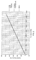
Figure 2 is a graph showing how the resonance of the cavity is matched with the peak acoustic frequency produced by a fan according to an example; and -
Figure 3 is a representation showing a proof of concept setup for a fixed Helmholtz resonator according to an example. - Example embodiments are described below in sufficient detail to enable those of ordinary skill in the art to embody and implement the systems and processes herein described. It is important to understand that embodiments can be provided in many alternate forms and should not be construed as limited to the examples set forth herein.
- Accordingly, while embodiments can be modified in various ways and take on various alternative forms, specific embodiments thereof are shown in the drawings and described in detail below as examples. There is no intent to limit to the particular forms disclosed. On the contrary, all modifications, equivalents, and alternatives falling within the scope of the appended claims should be included. Elements of the example embodiments are consistently denoted by the same reference numerals throughout the drawings and detailed description where appropriate.
- The terminology used herein to describe embodiments is not intended to limit the scope. The articles "a," "an," and "the" are singular in that they have a single referent, however the use of the singular form in the present document should not preclude the presence of more than one referent. In other words, elements referred to in the singular can number one or more, unless the context clearly indicates otherwise. It will be further understood that the terms "comprises," "comprising," "includes," and/or "including," when used herein, specify the presence of stated features, items, steps, operations, elements, and/or components, but do not preclude the presence or addition of one or more other features, items, steps, operations, elements, components, and/or groups thereof.
- Unless otherwise defined, all terms (including technical and scientific terms) used herein are to be interpreted as is customary in the art. It will be further understood that terms in common usage should also be interpreted as is customary in the relevant art and not in an idealized or overly formal sense unless expressly so defined herein.
- In order to compensate for the peak frequency being emitted by a gas flow system, a resonator cavity or chamber such as a Helmholtz cavity can be used. A Helmholtz cavity is defined by a volume of air with a neck. If the neck is in fluid communication with an air or gas flow this allows the system to resonate due to the change of pressure. This phenomenon can be observed by blowing across the top of a bottle for example - the sound you hear is the Helmholtz resonance. The resonant frequency of a Helmholtz chamber is governed by the volume of the cavity and the neck size, that is, the neck area of the cavity that is open to the airflow.
- When coupled to the side of a pipe or conduit (for example) with sound propagating through, a Helmholtz chamber can attenuate the sound almost completely at any frequency range due to destructive interference when the acoustic frequency matches the resonance of the Helmholtz chamber. By dynamically/actively varying the parameters of the Helmholtz chamber the resonant frequency of the chamber can be made to match the peak acoustic frequency of the source.
- Semi-passive solutions are known in which a Helmholtz cavity can be fitted with a moving wall and piston etc. that is controlled using active means, such as a motor. Active sensing and processing of the sound spectrum is performed in order to be able to adjust the parameters of the Helmholtz cavity in order to cancel out or reduce acoustic emissions. Such systems are typically, as a result of the active components, rather bulky and complicated, and require power and processing capabilities to be able to function.
- According to an example, an adjustable resonator assembly is provided that uses the airflow (or flow of other gaseous material) from a source to passively change a neck width, and thus the neck area, of a resonator cavity in the form of a Helmholtz resonator so as to vary the attenuation frequency to follow the corresponding changing acoustic frequency from the source. No active signal processing and manipulation is needed since all dynamic properties come directly from the airflow making the assembly totally passive. That is, an air or gas flow present in a conduit is used in order to adjust the dimensions of a resonator cavity.
-
Figure 1 is a schematic representation of an adjustable resonator assembly according to an example. The assembly comprises aresonator cavity 100 configurable to be in fluid communication with aconduit 103 through which air or another gaseous material can flow. Aresonator adjustment structure 105 is provided that is connected to a movabletop portion 107 of theresonator cavity 100. Theresonator adjustment structure 105 extends outside of theresonator cavity 100. Amechanism 109 to bias theresonator adjustment structure 105 in a first configuration in which the neck area I I 1 theresonator cavity 100 is substantially zero is provided. In an example, themechanism 109 is a spring having a preselected spring constant. - As will be explained in more detail below, the
resonator adjustment structure 105 is configured to modify the position of thetop portion 107 in the presence of an air or gaseous material flow within theconduit 103. Changing the position of thetop portion 107 modifies theneck area 111 of thecavity 100. Furthermore, thetop portion 107 is connected to a movableside wall portion 113. As the position of this portion changes, the volume of the cavity changes. Accordingly, the resonant frequency of thecavity 100 can be modified. - The airflow A from a source S is therefore used to passively change the neck width x of
cavity 100, whereby to vary the attenuation frequency in order to follow the corresponding changing acoustic frequency from the source S. This requires no additional active signal processing and manipulation, all dynamic properties come directly from the airflow A making it totally passive. That is, according to an example, a drag plate used to modify the properties of a resonator cavity has a step-like form (figure 1 ) with oneflap 105 inside theflow conduit 103 and anotherflap 107 covering the opening of theneck 111 and athird flap 113 being in contact with thespring 109. As the flow within theconduit 103 increases, the force of the flow drags theupper flap 105 which thereby opens theneck 111 and compresses thespring 109 at the same time while the spring constantly pushes in the opposite direction against theflap 113. - According to an example, the attenuation frequency of the
resonator cavity 100 can be calculated using: - The compression value (e.g. the spring constant) of the
mechanism 109; - The drag force experienced by the
resonator adjustment structure 105; and - The Helmholtz chamber resonance of the
cavity 100. - The following nomenclature is used hereinafter:
Symbol SI Units Meaning AD m2 Drag Surface Area Af m2 Area of flow pipe AH m2 Area of Helmholtz Chamber Neck Opening CD - Drag Coefficient FD N Drag Force ff Hz Fan Peak Acoustic Frequency fH Hz Helmholtz Resonant Frequency Fs N Spring Compression Force k N m-1 Spring Constant L m Length (Height) of Helmholtz Neck. N Hz Fan Speed n - Number of Blades on Fan q m3s-1 Flow V0 m3 Helmholtz Volume x m Spring Compression Movement (depth) y m Non variable neck dimension. (Width) Va m s-1 Air Velocity VS ms-1 Speed of Sound ρ kg m-3 Air Density - The spring compression force of the
mechanism 109 can be set equal to the drag force of theresonator adjustment structure 105 given by the respective equations:

- This can then combined with the Helmholtz Chamber resonant frequency equation, where the neck area (AH) 111 consists of 2 dimensions, x and y, as shown in
figure 1 , where:

- The value of x can then be substituted between equations 1 and 2 to give the air velocity dependent equation for the Helmholtz resonance, as shown below in equation 3:

- Equation 3 is universal to all air flow sources and, to make use of it, the resonant frequency can be matched to the peak frequency being emitted by the air flow source on a case specific basis.
- Consider the example of a fan. The fan affinity laws state that the air flow produced by a fan is directly proportional to its speed (when the fan diameter is held constant). Accordingly:

- Accordingly, q ∝ N, and so, if the constant of proportionality is known (the increase in flow for every extra 1 hertz of frequency of rotation), then the flow can be calculated for all speeds of the fan.
- The peak acoustic frequency of fan blades can be calculated by the product of the fan's speed and the number of blades:

- The dimensions and properties of the Helmholtz generator and spring setup can therefore be tuned to match the peak acoustic frequency of the fan.
- A representative set of variables for the case of a fan, can be as follows:
Spring constant (Nm) 10 Conduit Radius (mm) 25 Initial Neck width (x, mm) 0 Height of neck (L, mm) 15 Depth of neck (y, mm) 17 Radius of Helmholtz volume (mm) 25 Length of volume (mm) 49 No. fan blades 7 Height of adjustment structure (mm) 15 Fan Speed Flow Relationship (cm3/(s.Hz)) 440 -
Figure 2 is a graph showing how the resonance of the cavity is matched with the peak acoustic frequency produced by a fan according to an example, using the above parameters. Modifications could be made to produce predictions for other situations such as internal combustion engines and air compressors for example. - In the case of a fan, the assumptions that are made are as follows:
- The drag coefficient for the drag surface is 2.0 to represent a 2D flat plane
- Fan blade diameter remains constant (no expansion)
- The adjustment structure is in the form of a drag plate which is the same depth as the Helmholtz neck
- The moving drag plate mechanism has no effect on the Helmholtz resonance relationship
- Effective Length of the neck is the length of neck (no end effects)
- Air density and speed of sound are standard sea level atmospheric values
-
Figure 3 is a representation showing a proof of concept setup for a fixedHelmholtz resonator apparatus 300 according to an example. Tones were played through thespeaker 301 at the rear and when the frequency matched the resonant frequency predicted by the Helmholtz resonance equation, the sound leaving thetube 303 dropped to near silent. This could be heard in contrast without the effects of the Helmholtz resonance attenuation by covering the opening of theresonator 305 with a thin material. - The present inventions can be embodied in other specific apparatus and/or methods. The described embodiments are to be considered in all respects as illustrative and not restrictive. In particular, the scope of the invention is indicated by the appended claims rather than by the description and figures herein. All changes that come within the meaning and range of equivalency of the claims are to be embraced within their scope.
Claims (12)
- An adjustable resonator assembly, comprising:a resonator cavity having a neck area with a neck opening configurable to be in fluid communication with a conduit through which a gaseous material can flow;a resonator adjustment structure configured to move from a first position in which the structure closes the neck area when flow of the gaseous material is absent to a second position in which the structure opens the neck area by a predetermined degree in the presence of a flow of the gaseous material; anda bias mechanism configured to exert a force onto the resonator adjustment structure so as to move the resonator adjustment structure to the first position.
- An adjustable resonator assembly as claimed in claim 1, wherein, in the second position, the resonator cavity has a selected neck area, whereby to cause the resonator cavity to act as a Helmholtz chamber.
- An adjustable resonator assembly as claimed in claim 1 or 2, wherein the bias mechanism is a spring with a preselected spring constant.
- An adjustable resonator assembly as claimed in any preceding claim, wherein the resonator adjustment structure comprises a plate configured to extend radially inwardly into the conduit.
- An adjustable resonator assembly as claimed in claim 4, wherein the plate is arranged on an extension portion attached to a side wall portion.
- An adjustable resonator assembly as claimed in any preceding claim, wherein the size of the neck opening is variable between the first position and the second position.
- An adjustable resonator assembly as claimed in any preceding claim, wherein the resonator adjustment structure is biased using a spring having a preselected spring constant whereby to provide a spring compression force equal to a drag force of the resonator adjustment structure when exposed to the flow of the gaseous material.
- A method for reducing acoustic emissions in a gas flow system, the method comprising:modifying the area of a neck opening of and the volume of a resonator cavity exposed to a gas flow of the system whereby to match a peak acoustic frequency emitted by the gas flow system to the resonant frequency of the resonator cavity by varying the neck area of the cavity using a resonator adjustment structure.
- A method as claimed in claim 8, further including biasing the resonator adjustment structure in a first configuration in which the area of the neck opening of the resonator cavity is substantially zero.
- A method as claimed in claim 8 or 9, further comprising exposing the resonator adjustment structure to a gas flow of the system.
- A method as claimed in any of claims 8 to 10, wherein the resonator adjustment structure is biased using a spring, the method further comprising selecting a spring with a spring constant whereby to provide a spring compression force equal to a drag force of the exposed resonator adjustment structure.
- A method as claimed in any of claims 8 to 11, wherein modifying the area of the neck further comprises:adjusting the neck opening of the resonator cavity using an extension portion attached or otherwise arranged on a side wall portion of the cavity.
Priority Applications (1)
| Application Number | Priority Date | Filing Date | Title |
|---|---|---|---|
| EP15306615.4A EP3156664B1 (en) | 2015-10-13 | 2015-10-13 | An adjustable resonator assembly and a method for reducing acoustic emissions in a gas flow system |
Applications Claiming Priority (1)
| Application Number | Priority Date | Filing Date | Title |
|---|---|---|---|
| EP15306615.4A EP3156664B1 (en) | 2015-10-13 | 2015-10-13 | An adjustable resonator assembly and a method for reducing acoustic emissions in a gas flow system |
Publications (2)
| Publication Number | Publication Date |
|---|---|
| EP3156664A1 true EP3156664A1 (en) | 2017-04-19 |
| EP3156664B1 EP3156664B1 (en) | 2020-09-16 |
Family
ID=54545046
Family Applications (1)
| Application Number | Title | Priority Date | Filing Date |
|---|---|---|---|
| EP15306615.4A Active EP3156664B1 (en) | 2015-10-13 | 2015-10-13 | An adjustable resonator assembly and a method for reducing acoustic emissions in a gas flow system |
Country Status (1)
| Country | Link |
|---|---|
| EP (1) | EP3156664B1 (en) |
Citations (5)
| Publication number | Priority date | Publication date | Assignee | Title |
|---|---|---|---|---|
| DE9405771U1 (en) * | 1994-04-07 | 1994-08-25 | Gillet Heinrich Gmbh | Silencer with switchable damping characteristics |
| DE19600515A1 (en) * | 1995-01-09 | 1996-07-11 | Unisia Jecs Corp | Resonant sound damping system for inlet manifold of motor vehicle IC engine |
| US5821474A (en) * | 1995-11-02 | 1998-10-13 | Heinrich Gillet Gmbh & Co. Kg | Muffler with variable damping characteristics |
| EP1624251A1 (en) * | 2004-08-03 | 2006-02-08 | Siemens Aktiengesellschaft | apparatus for reducing thermoacoustic oscillations in combustion chambers with adjustable resonance frequency |
| US20070292261A1 (en) * | 2006-06-15 | 2007-12-20 | Punan Tang | System and method for noise suppression |
Family Cites Families (1)
| Publication number | Priority date | Publication date | Assignee | Title |
|---|---|---|---|---|
| US20150152819A1 (en) * | 2013-12-04 | 2015-06-04 | Mann+Hummel Gmbh | Self-adjusting resonator |
-
2015
- 2015-10-13 EP EP15306615.4A patent/EP3156664B1/en active Active
Patent Citations (5)
| Publication number | Priority date | Publication date | Assignee | Title |
|---|---|---|---|---|
| DE9405771U1 (en) * | 1994-04-07 | 1994-08-25 | Gillet Heinrich Gmbh | Silencer with switchable damping characteristics |
| DE19600515A1 (en) * | 1995-01-09 | 1996-07-11 | Unisia Jecs Corp | Resonant sound damping system for inlet manifold of motor vehicle IC engine |
| US5821474A (en) * | 1995-11-02 | 1998-10-13 | Heinrich Gillet Gmbh & Co. Kg | Muffler with variable damping characteristics |
| EP1624251A1 (en) * | 2004-08-03 | 2006-02-08 | Siemens Aktiengesellschaft | apparatus for reducing thermoacoustic oscillations in combustion chambers with adjustable resonance frequency |
| US20070292261A1 (en) * | 2006-06-15 | 2007-12-20 | Punan Tang | System and method for noise suppression |
Also Published As
| Publication number | Publication date |
|---|---|
| EP3156664B1 (en) | 2020-09-16 |
Similar Documents
| Publication | Publication Date | Title |
|---|---|---|
| US6792907B1 (en) | Helmholtz resonator | |
| KR100968590B1 (en) | Engine sound control apparatus | |
| EP0572492B1 (en) | Method and apparatus for attenuating acoustic vibrations in a medium | |
| CN103137123B (en) | Active design of exhaust sounds | |
| US20170241310A1 (en) | Acoustic device | |
| JPH01314500A (en) | Method and apparatus for active sound attenuation | |
| EP1970683A2 (en) | Systems and methods for predicting acoustic signatures | |
| CN111699376B (en) | Measuring device for determining a measurement parameter of a measurement gas | |
| WO1993021625A1 (en) | Extended frequency range helmholtz resonators | |
| DE19861018A1 (en) | Controlled acoustic waveguide for sound absorption | |
| EP0533916A1 (en) | Active noise control | |
| JP2005257720A (en) | Active noise control device | |
| KR20200129038A (en) | In-vehicle noise cancellation adaptive filter divergence control | |
| CN104064172B (en) | Vehicular Active Vibrational Noise Control Apparatus | |
| US8418804B1 (en) | Multiple Helmholtz resonators | |
| JP2007170228A (en) | Tone quality transmission structure | |
| CN114446276A (en) | Virtual position noise signal estimation for engine order cancellation | |
| EP3156664B1 (en) | An adjustable resonator assembly and a method for reducing acoustic emissions in a gas flow system | |
| EP1313090A2 (en) | Active noise control system with a Helmholtz resonator | |
| CN104832328B (en) | Adjustable resonator and its application method | |
| JP6373159B2 (en) | Intake sound amplifier for internal combustion engine for vehicle | |
| JP2007270687A (en) | Torque increase resonator | |
| Singh et al. | Tuning a semi-active Helmholtz resonator | |
| JPS61129414A (en) | Silencer device of adaptable type | |
| JP4626299B2 (en) | Duct noise control method and apparatus |
Legal Events
| Date | Code | Title | Description |
|---|---|---|---|
| PUAI | Public reference made under article 153(3) epc to a published international application that has entered the european phase |
Free format text: ORIGINAL CODE: 0009012 |
|
| STAA | Information on the status of an ep patent application or granted ep patent |
Free format text: STATUS: THE APPLICATION HAS BEEN PUBLISHED |
|
| AK | Designated contracting states |
Kind code of ref document: A1 Designated state(s): AL AT BE BG CH CY CZ DE DK EE ES FI FR GB GR HR HU IE IS IT LI LT LU LV MC MK MT NL NO PL PT RO RS SE SI SK SM TR |
|
| AX | Request for extension of the european patent |
Extension state: BA ME |
|
| STAA | Information on the status of an ep patent application or granted ep patent |
Free format text: STATUS: REQUEST FOR EXAMINATION WAS MADE |
|
| 17P | Request for examination filed |
Effective date: 20171019 |
|
| RBV | Designated contracting states (corrected) |
Designated state(s): AL AT BE BG CH CY CZ DE DK EE ES FI FR GB GR HR HU IE IS IT LI LT LU LV MC MK MT NL NO PL PT RO RS SE SI SK SM TR |
|
| RAP1 | Party data changed (applicant data changed or rights of an application transferred) |
Owner name: ALCATEL LUCENT |
|
| GRAP | Despatch of communication of intention to grant a patent |
Free format text: ORIGINAL CODE: EPIDOSNIGR1 |
|
| STAA | Information on the status of an ep patent application or granted ep patent |
Free format text: STATUS: GRANT OF PATENT IS INTENDED |
|
| INTG | Intention to grant announced |
Effective date: 20191115 |
|
| GRAJ | Information related to disapproval of communication of intention to grant by the applicant or resumption of examination proceedings by the epo deleted |
Free format text: ORIGINAL CODE: EPIDOSDIGR1 |
|
| STAA | Information on the status of an ep patent application or granted ep patent |
Free format text: STATUS: REQUEST FOR EXAMINATION WAS MADE |
|
| GRAP | Despatch of communication of intention to grant a patent |
Free format text: ORIGINAL CODE: EPIDOSNIGR1 |
|
| STAA | Information on the status of an ep patent application or granted ep patent |
Free format text: STATUS: GRANT OF PATENT IS INTENDED |
|
| INTC | Intention to grant announced (deleted) | ||
| INTG | Intention to grant announced |
Effective date: 20200401 |
|
| GRAS | Grant fee paid |
Free format text: ORIGINAL CODE: EPIDOSNIGR3 |
|
| GRAA | (expected) grant |
Free format text: ORIGINAL CODE: 0009210 |
|
| STAA | Information on the status of an ep patent application or granted ep patent |
Free format text: STATUS: THE PATENT HAS BEEN GRANTED |
|
| AK | Designated contracting states |
Kind code of ref document: B1 Designated state(s): AL AT BE BG CH CY CZ DE DK EE ES FI FR GB GR HR HU IE IS IT LI LT LU LV MC MK MT NL NO PL PT RO RS SE SI SK SM TR |
|
| REG | Reference to a national code |
Ref country code: GB Ref legal event code: FG4D |
|
| REG | Reference to a national code |
Ref country code: CH Ref legal event code: EP |
|
| REG | Reference to a national code |
Ref country code: DE Ref legal event code: R096 Ref document number: 602015059119 Country of ref document: DE |
|
| REG | Reference to a national code |
Ref country code: IE Ref legal event code: FG4D |
|
| REG | Reference to a national code |
Ref country code: AT Ref legal event code: REF Ref document number: 1314393 Country of ref document: AT Kind code of ref document: T Effective date: 20201015 |
|
| PG25 | Lapsed in a contracting state [announced via postgrant information from national office to epo] |
Ref country code: BG Free format text: LAPSE BECAUSE OF FAILURE TO SUBMIT A TRANSLATION OF THE DESCRIPTION OR TO PAY THE FEE WITHIN THE PRESCRIBED TIME-LIMIT Effective date: 20201216 Ref country code: SE Free format text: LAPSE BECAUSE OF FAILURE TO SUBMIT A TRANSLATION OF THE DESCRIPTION OR TO PAY THE FEE WITHIN THE PRESCRIBED TIME-LIMIT Effective date: 20200916 Ref country code: FI Free format text: LAPSE BECAUSE OF FAILURE TO SUBMIT A TRANSLATION OF THE DESCRIPTION OR TO PAY THE FEE WITHIN THE PRESCRIBED TIME-LIMIT Effective date: 20200916 Ref country code: NO Free format text: LAPSE BECAUSE OF FAILURE TO SUBMIT A TRANSLATION OF THE DESCRIPTION OR TO PAY THE FEE WITHIN THE PRESCRIBED TIME-LIMIT Effective date: 20201216 Ref country code: GR Free format text: LAPSE BECAUSE OF FAILURE TO SUBMIT A TRANSLATION OF THE DESCRIPTION OR TO PAY THE FEE WITHIN THE PRESCRIBED TIME-LIMIT Effective date: 20201217 Ref country code: HR Free format text: LAPSE BECAUSE OF FAILURE TO SUBMIT A TRANSLATION OF THE DESCRIPTION OR TO PAY THE FEE WITHIN THE PRESCRIBED TIME-LIMIT Effective date: 20200916 |
|
| REG | Reference to a national code |
Ref country code: AT Ref legal event code: MK05 Ref document number: 1314393 Country of ref document: AT Kind code of ref document: T Effective date: 20200916 |
|
| REG | Reference to a national code |
Ref country code: NL Ref legal event code: MP Effective date: 20200916 |
|
| PG25 | Lapsed in a contracting state [announced via postgrant information from national office to epo] |
Ref country code: LV Free format text: LAPSE BECAUSE OF FAILURE TO SUBMIT A TRANSLATION OF THE DESCRIPTION OR TO PAY THE FEE WITHIN THE PRESCRIBED TIME-LIMIT Effective date: 20200916 Ref country code: RS Free format text: LAPSE BECAUSE OF FAILURE TO SUBMIT A TRANSLATION OF THE DESCRIPTION OR TO PAY THE FEE WITHIN THE PRESCRIBED TIME-LIMIT Effective date: 20200916 |
|
| REG | Reference to a national code |
Ref country code: LT Ref legal event code: MG4D |
|
| PG25 | Lapsed in a contracting state [announced via postgrant information from national office to epo] |
Ref country code: CZ Free format text: LAPSE BECAUSE OF FAILURE TO SUBMIT A TRANSLATION OF THE DESCRIPTION OR TO PAY THE FEE WITHIN THE PRESCRIBED TIME-LIMIT Effective date: 20200916 Ref country code: SM Free format text: LAPSE BECAUSE OF FAILURE TO SUBMIT A TRANSLATION OF THE DESCRIPTION OR TO PAY THE FEE WITHIN THE PRESCRIBED TIME-LIMIT Effective date: 20200916 Ref country code: RO Free format text: LAPSE BECAUSE OF FAILURE TO SUBMIT A TRANSLATION OF THE DESCRIPTION OR TO PAY THE FEE WITHIN THE PRESCRIBED TIME-LIMIT Effective date: 20200916 Ref country code: EE Free format text: LAPSE BECAUSE OF FAILURE TO SUBMIT A TRANSLATION OF THE DESCRIPTION OR TO PAY THE FEE WITHIN THE PRESCRIBED TIME-LIMIT Effective date: 20200916 Ref country code: PT Free format text: LAPSE BECAUSE OF FAILURE TO SUBMIT A TRANSLATION OF THE DESCRIPTION OR TO PAY THE FEE WITHIN THE PRESCRIBED TIME-LIMIT Effective date: 20210118 Ref country code: LT Free format text: LAPSE BECAUSE OF FAILURE TO SUBMIT A TRANSLATION OF THE DESCRIPTION OR TO PAY THE FEE WITHIN THE PRESCRIBED TIME-LIMIT Effective date: 20200916 Ref country code: NL Free format text: LAPSE BECAUSE OF FAILURE TO SUBMIT A TRANSLATION OF THE DESCRIPTION OR TO PAY THE FEE WITHIN THE PRESCRIBED TIME-LIMIT Effective date: 20200916 |
|
| PG25 | Lapsed in a contracting state [announced via postgrant information from national office to epo] |
Ref country code: ES Free format text: LAPSE BECAUSE OF FAILURE TO SUBMIT A TRANSLATION OF THE DESCRIPTION OR TO PAY THE FEE WITHIN THE PRESCRIBED TIME-LIMIT Effective date: 20200916 Ref country code: AT Free format text: LAPSE BECAUSE OF FAILURE TO SUBMIT A TRANSLATION OF THE DESCRIPTION OR TO PAY THE FEE WITHIN THE PRESCRIBED TIME-LIMIT Effective date: 20200916 Ref country code: AL Free format text: LAPSE BECAUSE OF FAILURE TO SUBMIT A TRANSLATION OF THE DESCRIPTION OR TO PAY THE FEE WITHIN THE PRESCRIBED TIME-LIMIT Effective date: 20200916 Ref country code: PL Free format text: LAPSE BECAUSE OF FAILURE TO SUBMIT A TRANSLATION OF THE DESCRIPTION OR TO PAY THE FEE WITHIN THE PRESCRIBED TIME-LIMIT Effective date: 20200916 Ref country code: IS Free format text: LAPSE BECAUSE OF FAILURE TO SUBMIT A TRANSLATION OF THE DESCRIPTION OR TO PAY THE FEE WITHIN THE PRESCRIBED TIME-LIMIT Effective date: 20210116 |
|
| REG | Reference to a national code |
Ref country code: CH Ref legal event code: PL |
|
| REG | Reference to a national code |
Ref country code: DE Ref legal event code: R097 Ref document number: 602015059119 Country of ref document: DE |
|
| PG25 | Lapsed in a contracting state [announced via postgrant information from national office to epo] |
Ref country code: LU Free format text: LAPSE BECAUSE OF NON-PAYMENT OF DUE FEES Effective date: 20201013 Ref country code: MC Free format text: LAPSE BECAUSE OF FAILURE TO SUBMIT A TRANSLATION OF THE DESCRIPTION OR TO PAY THE FEE WITHIN THE PRESCRIBED TIME-LIMIT Effective date: 20200916 Ref country code: SK Free format text: LAPSE BECAUSE OF FAILURE TO SUBMIT A TRANSLATION OF THE DESCRIPTION OR TO PAY THE FEE WITHIN THE PRESCRIBED TIME-LIMIT Effective date: 20200916 |
|
| REG | Reference to a national code |
Ref country code: BE Ref legal event code: MM Effective date: 20201031 |
|
| PLBE | No opposition filed within time limit |
Free format text: ORIGINAL CODE: 0009261 |
|
| STAA | Information on the status of an ep patent application or granted ep patent |
Free format text: STATUS: NO OPPOSITION FILED WITHIN TIME LIMIT |
|
| 26N | No opposition filed |
Effective date: 20210617 |
|
| PG25 | Lapsed in a contracting state [announced via postgrant information from national office to epo] |
Ref country code: SI Free format text: LAPSE BECAUSE OF FAILURE TO SUBMIT A TRANSLATION OF THE DESCRIPTION OR TO PAY THE FEE WITHIN THE PRESCRIBED TIME-LIMIT Effective date: 20200916 Ref country code: LI Free format text: LAPSE BECAUSE OF NON-PAYMENT OF DUE FEES Effective date: 20201031 Ref country code: DK Free format text: LAPSE BECAUSE OF FAILURE TO SUBMIT A TRANSLATION OF THE DESCRIPTION OR TO PAY THE FEE WITHIN THE PRESCRIBED TIME-LIMIT Effective date: 20200916 Ref country code: CH Free format text: LAPSE BECAUSE OF NON-PAYMENT OF DUE FEES Effective date: 20201031 Ref country code: BE Free format text: LAPSE BECAUSE OF NON-PAYMENT OF DUE FEES Effective date: 20201031 |
|
| PG25 | Lapsed in a contracting state [announced via postgrant information from national office to epo] |
Ref country code: FR Free format text: LAPSE BECAUSE OF NON-PAYMENT OF DUE FEES Effective date: 20201116 Ref country code: IT Free format text: LAPSE BECAUSE OF FAILURE TO SUBMIT A TRANSLATION OF THE DESCRIPTION OR TO PAY THE FEE WITHIN THE PRESCRIBED TIME-LIMIT Effective date: 20200916 Ref country code: IE Free format text: LAPSE BECAUSE OF NON-PAYMENT OF DUE FEES Effective date: 20201013 |
|
| PGFP | Annual fee paid to national office [announced via postgrant information from national office to epo] |
Ref country code: GB Payment date: 20210831 Year of fee payment: 7 |
|
| PGFP | Annual fee paid to national office [announced via postgrant information from national office to epo] |
Ref country code: DE Payment date: 20210831 Year of fee payment: 7 |
|
| PG25 | Lapsed in a contracting state [announced via postgrant information from national office to epo] |
Ref country code: TR Free format text: LAPSE BECAUSE OF FAILURE TO SUBMIT A TRANSLATION OF THE DESCRIPTION OR TO PAY THE FEE WITHIN THE PRESCRIBED TIME-LIMIT Effective date: 20200916 Ref country code: MT Free format text: LAPSE BECAUSE OF FAILURE TO SUBMIT A TRANSLATION OF THE DESCRIPTION OR TO PAY THE FEE WITHIN THE PRESCRIBED TIME-LIMIT Effective date: 20200916 Ref country code: CY Free format text: LAPSE BECAUSE OF FAILURE TO SUBMIT A TRANSLATION OF THE DESCRIPTION OR TO PAY THE FEE WITHIN THE PRESCRIBED TIME-LIMIT Effective date: 20200916 |
|
| PG25 | Lapsed in a contracting state [announced via postgrant information from national office to epo] |
Ref country code: MK Free format text: LAPSE BECAUSE OF FAILURE TO SUBMIT A TRANSLATION OF THE DESCRIPTION OR TO PAY THE FEE WITHIN THE PRESCRIBED TIME-LIMIT Effective date: 20200916 |
|
| REG | Reference to a national code |
Ref country code: DE Ref legal event code: R119 Ref document number: 602015059119 Country of ref document: DE |
|
| GBPC | Gb: european patent ceased through non-payment of renewal fee |
Effective date: 20221013 |
|
| PG25 | Lapsed in a contracting state [announced via postgrant information from national office to epo] |
Ref country code: DE Free format text: LAPSE BECAUSE OF NON-PAYMENT OF DUE FEES Effective date: 20230503 |
|
| PG25 | Lapsed in a contracting state [announced via postgrant information from national office to epo] |
Ref country code: GB Free format text: LAPSE BECAUSE OF NON-PAYMENT OF DUE FEES Effective date: 20221013 |