EP3156646A1 - Windenergieanlage mit einem drehzahl- und einem generatorregler - Google Patents
Windenergieanlage mit einem drehzahl- und einem generatorregler Download PDFInfo
- Publication number
- EP3156646A1 EP3156646A1 EP15190145.1A EP15190145A EP3156646A1 EP 3156646 A1 EP3156646 A1 EP 3156646A1 EP 15190145 A EP15190145 A EP 15190145A EP 3156646 A1 EP3156646 A1 EP 3156646A1
- Authority
- EP
- European Patent Office
- Prior art keywords
- control
- speed
- power
- setpoint
- pitch
- Prior art date
- Legal status (The legal status is an assumption and is not a legal conclusion. Google has not performed a legal analysis and makes no representation as to the accuracy of the status listed.)
- Granted
Links
Images



Classifications
-
- F—MECHANICAL ENGINEERING; LIGHTING; HEATING; WEAPONS; BLASTING
- F03—MACHINES OR ENGINES FOR LIQUIDS; WIND, SPRING, OR WEIGHT MOTORS; PRODUCING MECHANICAL POWER OR A REACTIVE PROPULSIVE THRUST, NOT OTHERWISE PROVIDED FOR
- F03D—WIND MOTORS
- F03D7/00—Controlling wind motors
- F03D7/02—Controlling wind motors the wind motors having rotation axis substantially parallel to the air flow entering the rotor
- F03D7/04—Automatic control; Regulation
- F03D7/042—Automatic control; Regulation by means of an electrical or electronic controller
-
- F—MECHANICAL ENGINEERING; LIGHTING; HEATING; WEAPONS; BLASTING
- F03—MACHINES OR ENGINES FOR LIQUIDS; WIND, SPRING, OR WEIGHT MOTORS; PRODUCING MECHANICAL POWER OR A REACTIVE PROPULSIVE THRUST, NOT OTHERWISE PROVIDED FOR
- F03D—WIND MOTORS
- F03D1/00—Wind motors with rotation axis substantially parallel to the air flow entering the rotor
- F03D1/06—Rotors
-
- F—MECHANICAL ENGINEERING; LIGHTING; HEATING; WEAPONS; BLASTING
- F03—MACHINES OR ENGINES FOR LIQUIDS; WIND, SPRING, OR WEIGHT MOTORS; PRODUCING MECHANICAL POWER OR A REACTIVE PROPULSIVE THRUST, NOT OTHERWISE PROVIDED FOR
- F03D—WIND MOTORS
- F03D7/00—Controlling wind motors
- F03D7/02—Controlling wind motors the wind motors having rotation axis substantially parallel to the air flow entering the rotor
- F03D7/022—Adjusting aerodynamic properties of the blades
- F03D7/0224—Adjusting blade pitch
-
- F—MECHANICAL ENGINEERING; LIGHTING; HEATING; WEAPONS; BLASTING
- F03—MACHINES OR ENGINES FOR LIQUIDS; WIND, SPRING, OR WEIGHT MOTORS; PRODUCING MECHANICAL POWER OR A REACTIVE PROPULSIVE THRUST, NOT OTHERWISE PROVIDED FOR
- F03D—WIND MOTORS
- F03D7/00—Controlling wind motors
- F03D7/02—Controlling wind motors the wind motors having rotation axis substantially parallel to the air flow entering the rotor
- F03D7/0276—Controlling wind motors the wind motors having rotation axis substantially parallel to the air flow entering the rotor controlling rotor speed, e.g. variable speed
-
- F—MECHANICAL ENGINEERING; LIGHTING; HEATING; WEAPONS; BLASTING
- F03—MACHINES OR ENGINES FOR LIQUIDS; WIND, SPRING, OR WEIGHT MOTORS; PRODUCING MECHANICAL POWER OR A REACTIVE PROPULSIVE THRUST, NOT OTHERWISE PROVIDED FOR
- F03D—WIND MOTORS
- F03D7/00—Controlling wind motors
- F03D7/02—Controlling wind motors the wind motors having rotation axis substantially parallel to the air flow entering the rotor
- F03D7/04—Automatic control; Regulation
- F03D7/042—Automatic control; Regulation by means of an electrical or electronic controller
- F03D7/043—Automatic control; Regulation by means of an electrical or electronic controller characterised by the type of control logic
-
- F—MECHANICAL ENGINEERING; LIGHTING; HEATING; WEAPONS; BLASTING
- F03—MACHINES OR ENGINES FOR LIQUIDS; WIND, SPRING, OR WEIGHT MOTORS; PRODUCING MECHANICAL POWER OR A REACTIVE PROPULSIVE THRUST, NOT OTHERWISE PROVIDED FOR
- F03D—WIND MOTORS
- F03D9/00—Adaptations of wind motors for special use; Combinations of wind motors with apparatus driven thereby; Wind motors specially adapted for installation in particular locations
- F03D9/20—Wind motors characterised by the driven apparatus
- F03D9/25—Wind motors characterised by the driven apparatus the apparatus being an electrical generator
-
- F—MECHANICAL ENGINEERING; LIGHTING; HEATING; WEAPONS; BLASTING
- F03—MACHINES OR ENGINES FOR LIQUIDS; WIND, SPRING, OR WEIGHT MOTORS; PRODUCING MECHANICAL POWER OR A REACTIVE PROPULSIVE THRUST, NOT OTHERWISE PROVIDED FOR
- F03D—WIND MOTORS
- F03D7/00—Controlling wind motors
- F03D7/02—Controlling wind motors the wind motors having rotation axis substantially parallel to the air flow entering the rotor
- F03D7/04—Automatic control; Regulation
- F03D7/042—Automatic control; Regulation by means of an electrical or electronic controller
- F03D7/043—Automatic control; Regulation by means of an electrical or electronic controller characterised by the type of control logic
- F03D7/045—Automatic control; Regulation by means of an electrical or electronic controller characterised by the type of control logic with model-based controls
-
- F—MECHANICAL ENGINEERING; LIGHTING; HEATING; WEAPONS; BLASTING
- F05—INDEXING SCHEMES RELATING TO ENGINES OR PUMPS IN VARIOUS SUBCLASSES OF CLASSES F01-F04
- F05B—INDEXING SCHEME RELATING TO WIND, SPRING, WEIGHT, INERTIA OR LIKE MOTORS, TO MACHINES OR ENGINES FOR LIQUIDS COVERED BY SUBCLASSES F03B, F03D AND F03G
- F05B2270/00—Control
- F05B2270/10—Purpose of the control system
- F05B2270/101—Purpose of the control system to control rotational speed (n)
-
- F—MECHANICAL ENGINEERING; LIGHTING; HEATING; WEAPONS; BLASTING
- F05—INDEXING SCHEMES RELATING TO ENGINES OR PUMPS IN VARIOUS SUBCLASSES OF CLASSES F01-F04
- F05B—INDEXING SCHEME RELATING TO WIND, SPRING, WEIGHT, INERTIA OR LIKE MOTORS, TO MACHINES OR ENGINES FOR LIQUIDS COVERED BY SUBCLASSES F03B, F03D AND F03G
- F05B2270/00—Control
- F05B2270/30—Control parameters, e.g. input parameters
- F05B2270/309—Rate of change of parameters
-
- Y—GENERAL TAGGING OF NEW TECHNOLOGICAL DEVELOPMENTS; GENERAL TAGGING OF CROSS-SECTIONAL TECHNOLOGIES SPANNING OVER SEVERAL SECTIONS OF THE IPC; TECHNICAL SUBJECTS COVERED BY FORMER USPC CROSS-REFERENCE ART COLLECTIONS [XRACs] AND DIGESTS
- Y02—TECHNOLOGIES OR APPLICATIONS FOR MITIGATION OR ADAPTATION AGAINST CLIMATE CHANGE
- Y02E—REDUCTION OF GREENHOUSE GAS [GHG] EMISSIONS, RELATED TO ENERGY GENERATION, TRANSMISSION OR DISTRIBUTION
- Y02E10/00—Energy generation through renewable energy sources
- Y02E10/70—Wind energy
- Y02E10/72—Wind turbines with rotation axis in wind direction
Definitions
- the present invention relates to a wind turbine with a speed controller that generates a control variable for a pitch control from a control difference in the speed and a generator controller that controls the generator, depending on a speed and a power setpoint.
- generator control also considers the generator control as a generator control by the inverter.
- WO 2015/078478 A1 a wind turbine is known, the feedforward of the blade pitch depending on a rate of change of external reference.
- the feedforward control serves to avoid power dips in the event of a rapid increase in the power fed in.
- the invention has for its object to provide a wind turbine, which can quickly perform a required increase in output without much mechanical stress.
- the wind energy plant according to the invention has a rotor which has at least one rotor blade which can be adjusted by a pitch control about its longitudinal axis and has a generator driven by the rotor.
- a speed controller is provided which generates a control variable in the speed of a control variable for the pitch control.
- a generator controller is provided, which controls the generator, depending on the speed and a power setpoint. The control of the generator can be done for example via a converter.
- Speed controller and generator controller are not necessarily designed as separate components or assemblies, but may also be part or component of a controller.
- the feedforward control determines a power setpoint and / or a speed setpoint from the power control value.
- the setpoint values from the power conductance it is possible, for example, to resort to system-specific ramps, by way of which a transiently changing conductance is converted into a slowly and / or continuously changing setpoint value.
- the pilot control is designed such that the power absorbed by the rotor is sufficient at least for the power setpoint and for an acceleration of the drive train.
- control variable of the pitch control is an adjustment speed for the blade pitch angle.
- the integrated over time Adjustment speed gives the angle value of the blade adjustment angle.
- the control variable of the pitch control can also be an adjustment angle, which is in the form of an angle increment or else as an absolute angle value.
- Fig. 1 shows an overview with controller and controller.
- a power conductance PL 8 which may be a value specified by a grid operator, is an input quantity at a block setpoint and feedforward control 10.
- a power setpoint can be derived from the power conductance PL 8 via corresponding ramps which, for example, specify a maximum power change of the wind energy plant PS 28 are determined, both sizes represent the maximum target performance of the wind turbine.
- a target speed nS 11 is generated by the block setpoint and feedforward control 10.
- a control variable for the pitch control dpit_FF / dt 15 is generated by the block setpoint and feedforward control 10. This is the temporal change of the Blatteinstellwinkels, in which case no setpoint is specified, but the value for feedforward control.
- the thus determined pitch speed dpit_n / dt 19 and the control variable for the pitch control dpit_FF / dt 15 are added in an adder 16 and the sum 21 is applied to an integrator PitInt 18.
- Output of the integrator PitInt 18 is the pitch angle Pit 20 to be set at the wind turbine.
- An actual value of the generator speed ngeni 22 is determined at the wind turbine and filtered in a filter ni_Filt 24 to achieve a filtered actual generator speed ngenF26.
- the filtered generator speed ngenF 26, together with the desired power value PS 28, is applied to a generator controller 30, which via the output signal 41 drives the main converter 32 of the wind energy plant.
- Fig. 1 The overview with controller and controller described describes a change in the pitch velocity as a function of the power conductance PL 8. It is a pre-control in which a balance of the power absorbed by the rotor and the generator power plus power to accelerate the drivetrain is sought. Since the performance curve is used to determine the desired relationship between power and speed, the pitch speed can be controlled via the feedforward control in such a way that the rotor absorbs as much power as required for acceleration and generator power. If the feedforward control is correctly set in the setpoint and pilot control 10 block and constant operating conditions, the n_Reg 14 speed controller hardly ever intervenes and strong mechanical loads, overshoots and other mechanical loading conditions for the wind turbine are avoided.
- a pitch rate is calculated, which adapts the actual power to the target power and the actual speed to the target speed.
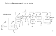
- the feedforward control 59 determines in a block M (P, n) 50 from the power setpoint PS 47 and the setpoint speed nS 49, the power-based torque M P 57.
- the derivative d / dt 51 of the setpoint speed nS 49 determines the change in the Speed taken into account in the wind turbine and calculated based on the acceleration torque M B 55.
- the sum of torque from power M P 57 and torque from acceleration M B 55 is further processed as pilot-controlled total torque MFF 53 in the pilot control 59.
- the torque is derived to "dMFF / dt".
- Gain Kp 52 determines the dynamic transient response of the feedback loop.
- block Limit 54 the output value is limited in height. This is necessary because the pitch drive is also subject to a speed limit.
- the feedback integrator Int 56 again integrates a torque which is subtracted from the torque MFF 53. By this construction, the derivative of the torque and thus the pitch angle is limited in size. At the same time, it is ensured that the integral of dMFF / dt despite limitation at the end corresponds to "MFF", or the entire pilot control pitch angle is traversed. Simply deriving and then limiting would stop the pilot pitch angle too soon.
- Fig. 3 shows an example of a route model to realize the pilot-controlled rate of change.
- a power setpoint PS 74 is determined with a ramp function P_Ramp 72 from the power conductance PL 70.
- nSM 78 Via the speed ramp n_Ramp 76, a desired speed model value nSM 78 is determined.
- a regulator torque MrM 90 is determined via a pilot controller 86 for the model.
- the modeled generator torque MgvM 88 is determined via the power setpoint PS 74 and the desired speed model value nSM 78 in block M (P, n) 84.
- the sum of the modeled generator torque MgvM 88 and the controller torque MrM 90 is formed in an adder 92 and applied as a signal 94 to a limiter limit 96.
- the limiter limit 96 takes into account the actual structure of the wind turbine and generates the pilot controlled total torque MFF 98.
- the total torque MFF 98 is derived in d / dt 102 and converted via a Gaintuning function GT 106 in the pilot-controlled pitch angle change rate dpitFF / dt 108.
- the matching speed nS 114 is determined via the moment of inertia J_ ts 112 of the drive train, in which case to obtain only a modeled acceleration torque, a modeled generator torque MgenM 118 is determined via a modeled generator controller 116. This then results in the speed setpoint nS 114 matching the pitch angle changing speed dpitFF / dt 108.
- This design uses a model of the plant. It includes the moment of inertia J_ ts 112 of the powertrain, the regulation of the generator torque in the generator controller 116 and all relevant limitations. Considered are e.g. the limitation of the pitching speed "dpitFF / dt” or a limitation of the rotor-generated torque change “dMFF / dt", a limiting of the driveline speed change rate "dns / dt” and a limitation of the power increase or the generator torque increase "dMgen_M / dt". If one of these values is limited, the output signal MFF 98 of the limiter Limit 96 is limited.
- a controller which calculates a speed error 82 from the pre-control setpoint speed nSM 78 and the model speed nS 114. For this is in the feedforward controller 86 the Moment MrM 90 calculated. Many control algorithms are possible.
- the pre-control generator torque MgvM 88 is formed from the target power PS 74 and the pre-control target speed nSM 78. The sum of both moments, which is formed on the addition member 92, is performed as a signal 94 to the input of the limiter limit 96.
Landscapes
- Engineering & Computer Science (AREA)
- Mechanical Engineering (AREA)
- Sustainable Development (AREA)
- Sustainable Energy (AREA)
- Chemical & Material Sciences (AREA)
- Combustion & Propulsion (AREA)
- Life Sciences & Earth Sciences (AREA)
- General Engineering & Computer Science (AREA)
- Physics & Mathematics (AREA)
- Fluid Mechanics (AREA)
- Power Engineering (AREA)
- Wind Motors (AREA)
- Control Of Eletrric Generators (AREA)
Abstract
Description
- Die vorliegende Erfindung betrifft eine Windenergieanlage mit einem Drehzahlregler, der aus einer Regeldifferenz in der Drehzahl eine Steuergröße für eine Pitchsteuerung generiert und einem Generatorregler, der den Generator, abhängig von einer Drehzahl und einem Leistungssollwert, ansteuert. Bei der Generatoransteuerung wird je nach Konfiguration von Generator und Umrichter auch die Ansteuerung des Generators durch den Umrichter als eine Generatorsteuerung aufgefasst.
- Aus
EP 1 946 436 B1 ist ein Stromwandler bekannt, bei dem zwischen einem Gleichrichter und einem Wechselrichter ein Gleichstromzwischenkreis vorgesehen ist, dessen Spannungsniveau entsprechend einem Leistungsbedarf und einem Spannungsbedarfssignal geregelt wird. - Aus
EP 2 317 134 A2 ist ein Verfahren und eine Vorrichtung zur Leistungserzeugung in einer Windenergieanlage bekannt geworden, bei dem eine Störgrößenvorsteuerung zur Dämpfung von Stromschwingungen bei Schaltvorgängen vorgesehen ist. - Aus
US 2013/0148393 A1 ist ein Verfahren zur Ansteuerung eines Leistungswandlers bekannt, bei dem für einen Einbruch der Netzspannung (low voltage ride through LVRT) oder einen Zusammenbruch der Netzspannung (zero voltage ride through ZVRT) vorgesehen ist, ein Vorsteuerspannungssignal zur Bestimmung eines Spannungssollwerts anzusteuern. - Aus
WO 2015/078478 A1 ist eine Windenergieanlage bekannt, die eine Vorsteuerung des Blatteinstellwinkels abhängig von einer Änderungsrate einer externen Referenz aufweist. Die Vorsteuerung dient dazu, Leistungsdellen (power dips) bei einem schnellen Anstieg der eingespeisten Leistung zu vermeiden. - Bei bekannten Windenergieanlagen und Windparks kommt es bei einer vorgegebenen Änderung der Leistungsbegrenzung, beispielsweise durch die Windparksteuerung oder bei einem Anfahren einer Windenergieanlage stets zu Situationen, in denen die Leistung nicht ausreichend schnell ansteigt. Ferner tritt ein Überschwingen und ein Unterschwingen der Drehzahl und der Leistung auf, wodurch einzelne Windenergieanlagen einer erhöhten Belastung ausgesetzt sind.
- Der Erfindung liegt die Aufgabe zugrunde, eine Windenergieanlage bereitzustellen, die einen geforderten Leistungsanstieg ohne große mechanische Belastung schnell durchführen kann.
- Erfindungsgemäß wird die Aufgabe durch eine Windenergieanlage mit den Merkmalen aus Anspruch 1 gelöst. Vorteilhafte Ausgestaltungen bilden den Gegenstand der Unteransprüche.
- Die erfindungsgemäße Windenergieanlage besitzt einen Rotor, der mindestens ein über eine Pitchsteuerung um seine Längsachse verstellbares Rotorblatt aufweist und einen von dem Rotor angetriebenen Generator besitzt. Für den Betrieb der Windenergieanlage ist ein Drehzahlregler vorgesehen, der aus einer Regeldifferenz in der Drehzahl eine Steuergröße für die Pitchsteuerung generiert. Ferner ist ein Generatorregler vorgesehen, der den Generator, abhängig von der Drehzahl und einem Leistungssollwert, ansteuert. Die Ansteuerung des Generators kann beispielsweise über einen Umrichter erfolgen. Drehzahlregler und Generatorregler sind nicht notwendig als getrennte Bauteile oder Baugruppen ausgebildet, sondern können auch Bestandteil oder Komponente eines Reglers sein. Erfindungsgemäß ist eine Vorsteuerung vorgesehen, an der ein Leistungsleitwert als Eingangsgröße anliegt und die eine Steuergröße für die Pitchsteuerung als Ausgangsgröße ausgibt, wobei die ausgegebene Steuergröße für die Pitchsteuerung die Ausgangsgröße eines Drehzahlreglers vorsteuert. Die Vorsteuerung erfolgt über eine inverse Regelstrecke, die ein Leistungsdrehmoment aus dem Drehzahlsollwert und dem Leistungssollwert sowie ein Beschleunigungsdrehmoment aus der zeitlichen Änderung des Drehzahlsollwerts bestimmt. Die Vorsteuerung der Ausgangsgröße des Drehzahlreglers bewirkt, dass eine Steuergröße für die Pitchsteuerung abhängig von einem Leistungsleitwert gesteuert wird und der Drehzahlregler nicht in die Umsetzung des Leistungsleitwerts eingreift.
- In einer bevorzugten Ausgestaltung bestimmt die Vorsteuerung aus dem Leistungsleitwert einen Leistungssollwert und/oder einen Drehzahlsollwert. Bei der Bestimmung der Sollwerte aus dem Leistungsleitwert kann beispielsweise auf anlagenspezifische Rampen zurückgegriffen werden, über die ein sich sprunghaft ändernder Leitwert in einen sich langsam und/oder stetig ändernden Sollwert umgewandelt wird.
- In einer bevorzugten Ausgestaltung ist die Vorsteuerung derart ausgelegt, dass die von dem Rotor aufgenommene Leistung mindestens für den Leistungssollwert und für eine Beschleunigung des Triebstrangs ausreicht. Der Vorteil der Vorsteuerung einer Steuergröße für die Pitchsteuerung liegt darin, dass der Drehzahlregler nur wenig oder gar nicht eingreifen muss, so dass ein Überschwingen in Drehzahl und Leistung vermieden werden kann, ebenso wie starke mechanische Belastungen der Windenergieanlage.
- In einer bevorzugten Ausgestaltung ist die Steuergröße der Pitchsteuerung eine Verstellgeschwindigkeit für den Blatteinstellwinkel. Die über die Zeit integrierte Verstellgeschwindigkeit ergibt den Winkelwert des Blatteinstellwinkels. Auch kann die Steuergröße der Pitchsteuerung ein Verstellwinkel sein, der in Form eines Winkelinkrements oder auch als ein absoluter Winkelwert vorliegt.
- Ein Ausführungsbeispiel des erfindungsgemäßen Verfahrens wird nachfolgend näher erläutert. Es zeigen:
- Fig. 1
- eine Übersicht von Regler, Steuerung und Regelstrecke,
- Fig. 2
- die Bestimmung von Leistungssollwert, Drehzahlsollwert und Steuergröße für die Pitchsteuerung, wobei die Vorsteuerung über eine inverse Strecke erfolgt,
- Fig. 3
- eine beispielhafte Vorsteuerung mit einem Streckenmodell und
- Fig. 4
- einen zeitlichen Verlauf des Drehmoments und die zeitliche Entwicklung der Ableitung des Drehmoments nach der Zeit.
-
Fig. 1 zeigt eine Übersicht mit Regler und Steuerung. Ein Leistungsleitwert PL 8, bei dem es sich um einen von einem Netzbetreiber vorgegebenen Wert handeln kann, ist Eingangsgröße an einem Block Sollwert und Vorsteuerung 10. Über entsprechende Rampen, die beispielsweise eine maximale Leistungsänderung der Windenergieanlage vorgeben, kann aus dem Leistungsleitwert PL 8 ein Leistungssollwert PS 28 bestimmt werden, wobei beide Größen die maximale Solleistung der Windenergieanlage darstellen. Ebenfalls wird eine Solldrehzahl nS 11 durch den Block Sollwert und Vorsteuerung 10 erzeugt. Weiterhin wird durch den Block Sollwert und Vorsteuerung 10 eine Steuergröße für die Pitchsteuerung dpit_FF/dt 15 erzeugt. Hierbei handelt es sich um die zeitliche Änderung des Blatteinstellwinkels, wobei hier kein Sollwert vorgegeben wird, sondern der Wert zur Vorsteuerung. Über einen Filter nS_Filt 12 wird die Solldrehzahl nS 11 gefiltert, wobei hierdurch Phasenverschiebungen aus der Drehzahlfilterung, aus einem Pitchantrieb und weiteren Verzögerungen in der Regelstrecke kompensiert werden. Die gefilterte Solldrehzahl nSF 13 wird an einem Subtraktionsglied 9 mit einer gefilterten Generatordrehzahl ngenF 26 zusammengeführt und als Regeldifferenz 17 an einen Drehzahlregler n_Reg 14 angelegt. Der Drehzahlregler n_Reg 14 rechnet die Regeldifferenz in eine Pitchgeschwindigkeit dpit_n/dt 19 um. Der Drehzahlregler gleicht Störungen, wie beispielsweise eine schwankende Windgeschwindigkeit, durch die Vorgabe einer Pitchgeschwindigkeit aus. Die so ermittelte Pitchgeschwindigkeit dpit_n/dt 19 sowie die Steuergröße für die Pitchsteuerung dpit_FF/dt 15 werden in einem Additionsglied 16 addiert und die Summe 21 an einen Integrator PitInt 18 angelegt. Ausgangssignal des Integrators PitInt 18 ist der an der Windenergieanlage einzustellende Pitchwinkel Pit 20. Ein Istwert derGeneratordrehzahl ngeni 22 wird an der Windenergieanlage bestimmt und in einem Filter ni_Filt 24 gefiltert, um eine gefilterte Ist-Generatordrehzahl ngenF 26 zu erreichen. Die gefilterte Generatordrehzahl ngenF 26 liegt zusammen mit dem Leistungssollwert PS 28an einem Generatorregler 30 an, der über das Ausgangssignal 41 den Hauptumrichter 32 der Windenergieanlage ansteuert. - Um regelungstechnisch eine Steuergröße für die Pitchsteuerung dpit_FF/dt 15 als Steuersignal zur Vorsteuerung ermitteln zu können, ist es hilfreich, sich die Zusammenhänge in der Regelstrecke zu vergegenwärtigen. In dem Block M(Pit) 34 wird der anliegende Sollwert für den Pitchwinkel Pit 20 für den Blatteinstellwinkel gewandelt, woraus sich über den Ist-Pitchwinkel das dazugehörige Rotordrehmoment Mpit 36 ergibt. Das Rotordrehmoment Mpit 36 treibt den Triebstrang der Windenergieanlage an und ein sich aus der Ansteuerung des Hauptumlichters 32 ergebendes Generatordrehmoment Mgen 38 bremst diesen. Daher wird für ein resultierendes Drehmoment 39 in einem Subtraktionsglied 40 die Differenz gebildet. Das resultierende Drehmoment 39 wirkt über das Trägheitsmoment des Triebstrangs J_ts 42, um den Istwert der Generatordrehzahl ngeni 22 zu erzeugen. Dabei gilt der bekannte Zusammenhang n = 60 * M/(2 * Pi * J_ts).
- Bei der in
Fig. 1 dargestellten Übersicht mit Regler und Steuerung wird eine Änderung der Pitchgeschwindigkeit in Abhängigkeit des Leistungsleitwerts PL 8 beschrieben. Es handelt sich um eine Vorsteuerung, bei der ein Gleichgewicht der über den Rotor aufgenommenen Leistung und der Generatorleistung plus Leistung zum Beschleunigen des Triebstrangs angestrebt wird. Da über die Leistungskennlinie der gewünschte Zusammenhang von Leistung und Drehzahl vorgegeben ist, kann die Pitchgeschwindigkeit über die Vorsteuerung so gesteuert werden, dass der Rotor so viel Leistung aufnimmt, wie für Beschleunigung und Generatorleistung notwendig ist. Bei einer richtig eingestellten Vorsteuerung im Block Sollwert und Vorsteuerung 10 und konstanten Betriebsbedingungen, greift der Drehzahlregler n_Reg 14 so gut wie nicht ein und starke mechanische Belastungen, Überschwinger und andere mechanisch belastende Umstände für die Windenergieanlage werden vermieden. -
Fig. 2 zeigt eine erfindungsgemäße Ausführung, bei der über eine inverse Regelstrecke die Vorsteuerung erfolgt.Fig. 2 zeigt mithin eine Ausgestaltung der Sollwertbildung und Vorsteuerung gemäß Block 10 ausFig. 1 . Wie inFig. 2 dargestellt, wird der anliegende Leistungsleitwert PL 45 zunächst über eine Rampenfunktion P-Ramp 46 in einen Leistungssollwert PS 47 umgerechnet. Über eine weitere nachgeschaltete Drehzahlrampe n_Ramp 48 wird der Leistungsleitwert PL 45 in eine Solldrehzahl nS 49 umgerechnet. Die Solldrehzahl nS 49 liegt zusammen mit dem Leistungssollwert PS 47 an einem Vorsteuerblock 59 an. In der Vorsteuerung 59 wird eine Pitchgeschwindigkeit berechnet, die die Ist-Leistung an die Sollleistung und die Ist-Drehzahl an die Solldrehzahl anpasst. Die Vorsteuerung 59 ermittelt in einem Block M(P, n) 50 aus dem Leistungssollwert PS 47 und der Solldrehzahl nS 49, das auf der Leistung beruhende Drehmoment MP 57. Über die Ableitung d/dt 51 der Solldrehzahl nS 49 wird die Änderung der Drehzahl in der Windenergieanlage berücksichtigt und das auf der Beschleunigung beruhende Drehmoment MB 55 berechnet. Die Summe von Drehmoment aus Leistung MP 57 und Drehmoment aus Beschleunigung MB 55 wird als vorgesteuertes Gesamtdrehmoment MFF 53 in der Vorsteuerung 59 weiterverarbeitet. Das vorgesteuerte Gesamtdrehmoment MFF 53 wird über einen Verstärkungsblock Kp 52 und einen Begrenzungsblock Limit 54 abgeleitet, wobei der abgeleitete Wert dMFF/dt 64 über einen Integratorblock 56 als Signal 65 zurück zu einem Subtraktionsglied 62 geführt wird. Die Vorsteuerung 59 berücksichtigt über die vorgenommene Ableitung auch das Verhalten der Windenergieanlage. Die Ableitungsfunktion, bestehend aus den Blöcken 52, 54, 56 und 62 hat den Vorteil, dass Limitierungen der Pitchgeschwindigkeit aus dem Block Limit 54 berücksichtigt werden können und das Integral aus dMFF/dt 64 dem Wert MFF 53 entspricht. Die zeitliche Änderung des vorgesteuerten Gesamtdrehmoments wird über eine nichtlineare Gaintuning-Funktion GT 58 in die zeitliche Ableitung des vorgesteuerten Pitchwinkels dpitFF/dt 66 umgewandelt. Hierbei berechnet dpitFF/dt 66 sich als die zeitliche Ableitung des vorgesteuerten Blatteinstellwinkels aus der Soll-Drehmomentänderung dMFF/dt 64. - In den Blöcken 52, 54, 56 und 62 wird das Drehmoment abgeleitet zu "dMFF/dt". Durch die Verstärkung Kp 52 wird das dynamische Einschwingverhalten der Rückkopplungsschleife festgelegt. Im Block Limit 54 wird der Ausgangswert in der Höhe begrenzt. Dies ist nötig weil der Pitchantrieb auch einer Geschwindigkeitsbegrenzung unterliegt. Der rückgekoppelte Integrator Int 56 integriert wieder ein Drehmoment auf, das vom Drehmoment MFF 53 subtrahiert wird. Durch diesen Aufbau wird die Ableitung des Drehmoments und damit des Pitchwinkels in der Größe begrenzt. Gleichzeitig ist sichergestellt, dass das Integral von dMFF/dt trotz Begrenzung am Ende "MFF" entspricht, bzw. der gesamte Vorsteuer-Pitchwinkel verfahren wird. Ein einfaches Ableiten und anschließendes Begrenzen würde den Vorsteuer-Pitchwinkel zu früh stoppen.
- In
Fig. 4 ist dies zu sehen: Kp=4, Limit=4000, Anstieg MFF von 1000Nm auf 11000Nm. Die Größe dMFF/dt ist auf 4000Nm begrenzt. Unter ihrer Kurve befindet sich die Fläche von 10000Nm. Hingegen ist dM/dt nicht begrenzt. Der Pitchantrieb könnte nicht schnell genug folgen. Wäre dM/dt auf 4000Nm begrenzt, wäre die Fläche unter der Kurve zu klein und die Pitchwinkel würde nicht ausreichend weit verfahren. -
Fig. 3 zeigt beispielhaft ein Streckenmodell, um die vorgesteuerte Änderungsrate zu realisieren. Wiederum wird mit einer Rampenfunktion P_Ramp 72 aus dem Leistungsleitwert PL 70 ein Leistungssollwert PS 74 ermittelt. Über die Drehzahlrampe n_Ramp 76 wird ein Soll-Drehzahlmodellwert nSM 78 ermittelt. Über einen Vorsteuerungsregler 86 für das Modell wird ein Reglerdrehmoment MrM 90 bestimmt. Das modellierte Generatordrehmoment MgvM 88 wird über den Leistungssollwert PS 74 und den Soll-Drehzahlmodellwert nSM 78 in Block M(P, n) 84 bestimmt. Die Summe aus dem modellierten Generatordrehmoment MgvM 88 und dem Reglerdrehmoment MrM 90wird in einem Additionsglied 92 gebildet und liegt als Signal 94 an einem Begrenzer Limit 96 an. Der Begrenzer Limit 96 berücksichtigt den tatsächlichen Aufbau der Windenergieanlage und erzeugt das vorgesteuerte Gesamtdrehmoment MFF 98. Das Gesamtdrehmoment MFF 98 wird in d/dt 102 abgeleitet und über eine Gaintuning-Funktion GT 106 in die vorgesteuerte Pitchwinkeländerungsgeschwindigkeit dpitFF/dt 108 umgewandelt. - Die hierzu passende Drehzahl nS 114 wird über das Trägheitsmoment J_ ts 112 des Triebstrangs bestimmt, wobei hier um nur ein modelliertes Beschleunigungsdrehmoment zu erhalten, über einen modellierten Generatorregler 116 ein modelliertes Generatordrehmoment MgenM 118 ermittelt wird. Hieraus ergibt sich dann der zu der Pitchwinkeländerungsgeschwindigkeit dpitFF/dt 108passende Drehzahlsollwert nS 114.
- In diesem Entwurf wird ein Modell der Anlage (der Regelstrecke) verwendet. Es beinhaltet das Trägheitsmoment J_ ts 112 des Triebstrangs, die Regelung des Generatordrehmoments im Generatorregler 116 und alle relevanten Begrenzungen. Berücksichtigt sind z.B. die Begrenzung der Pitchgeschwindigkeit "dpitFF/dt" oder eine Begrenzung der vom Rotor erzeugten Drehmomentänderung "dMFF/dt", eine Begrenzung der Triebstrangdrehzahländerungsrate "dns/dt" und eine Begrenzung des Leistungsanstieges oder des Generatormomentenanstieges "dMgen_M/dt". Ist einer dieser Werte begrenzt, wird das Ausgangssignal MFF 98 des Begrenzers Limit 96 begrenzt. Ist das Signal 94 am Eingang der Begrenzung Limit 96 zu groß wird das Ausgangssignal MFF 98 so begrenzt, dass die Leistung und die Drehzahl in ihren Grenzen optimal ansteigen. Das Drehmoment des Rotors MFF 98 wird in d/dt 102 abgeleitet und über eine Gaintuning-Funktion in Block GT 106 in die Vorsteuer- Pitchgeschwindigkeit dpitFF/dt 108 umgerechnet. Da die Drehzahl nS 114 im Modell auf dem gleichen Drehmoment MFF 98 beruht wie die Vorsteuer-Pitchgeschwindigkeit dpitFF/dt 108, wird sie als Soll-Drehzahl für den Drehzahlregler der realen Anlage genutzt.
- Für die Erzeugung des Signals 94 am Eingang des Begrenzers Limit 96 sind mehrere Lösungen möglich. Hier wird ein Regler vorgeschlagen, der aus der Vorsteuer-Solldrehzahl nSM 78 und der Modell Drehzahl nS 114 einen Drehzahlfehler 82 berechnet. Aus diesem wird im Vorsteuerungsregler 86 das Moment MrM 90 berechnet. Viele Regelungsalgorithmen sind möglich. Zusätzlich wird aus der Sollleistung PS 74 und der Vorsteuer-Solldrehzahl nSM 78 das Vorsteuer-Generatormoment MgvM 88 gebildet. Die Summe beider Momente, die am Additionsglied 92 gebildet wird, wird als Signal 94 auf den Eingang des Begrenzers Limit 96 geführt.
Claims (6)
- Windenergieanlage mit einem Rotor, der mindestens ein über eine Pitchsteuerung um seine Längsachse verstellbares Rotorblatt aufweist, und einem von dem Rotor angetriebenen Generator mit- einem Drehzahlregler, der aus einer Regeldifferenz in der Drehzahl eine Steuergröße für die Pitchsteuerung generiert und- einem Generatorregler, der aus einem Leistungsleitwert einen Drehzahlsollwert und einen Leistungssollwert bestimmt,dadurch gekennzeichnet, dass
eine Vorsteuerung vorgesehen ist, die über eine inverse Regelstrecke eine Steuergröße für die Pitchsteuerung bestimmt, wobei die inverse Regelstrecke ein Leistungsdrehmoment (MP) aus dem Drehzahlsollwert und dem Leistungssollwert sowie ein Beschleunigungsdrehmoment (MB) aus der zeitlichen Änderung des Drehzahlsollwerts bestimmt und die Steuergröße für die Pitchsteuerung als Ausgangsgröße ausgibt, die die Ausgangsgröße des Drehzahlreglers vorsteuert. - Windenergieanlage nach Anspruch 1, dadurch gekennzeichnet, dass die Vorsteuerung aus dem Leistungsleitwert einen Leistungssollwert und/oder einen Drehzahlsollwert bestimmt.
- Windenergieanlage nach Anspruch 1 oder 2, dadurch gekennzeichnet, dass die Vorsteuerung derart ausgelegt ist, dass die von dem Rotor aufgenommene Leistung mindestens für ein Bereitstellen des Leistungssollwerts und für eine Beschleunigung des Triebstrangs ausreicht.
- Windenergieanlage nach einem der Ansprüche 1 bis 3, dadurch gekennzeichnet, dass die Steuergröße der Pitchsteuerung der Verstellgeschwindigkeit für den Blatteinstellwinkel entspricht.
- Windenergieanlage nach einem der Ansprüche 1 bis 4, dadurch gekennzeichnet, dass die die Steuergröße der Pitchsteuerung dem Verstellwinkel für den Blatteinstellwinkel entspricht.
- Windenergieanlage nach einem der Ansprüche 1 bis 5, dadurch gekennzeichnet, dass zu der Summe aus Leistungsdrehmoment und Beschleunigungsdrehmoment eine zeitliche Änderungsrate bestimmt wird, die an einer Verstärkung anliegt, um die auszugebende Steuergröße für die Pitchsteuerung zu ermitteln.
Priority Applications (4)
| Application Number | Priority Date | Filing Date | Title |
|---|---|---|---|
| EP15190145.1A EP3156646B1 (de) | 2015-10-16 | 2015-10-16 | Windenergieanlage mit einem drehzahl- und einem generatorregler |
| DK15190145.1T DK3156646T3 (en) | 2015-10-16 | 2015-10-16 | WIND ENERGY INSTALLATION WITH A SPEED AND GENERATOR REGULATOR |
| ES15190145.1T ES2683203T3 (es) | 2015-10-16 | 2015-10-16 | Turbina eólica con un controlador de velocidad y controlador de generador |
| US15/294,262 US10480488B2 (en) | 2015-10-16 | 2016-10-14 | Wind turbine with a speed regulator and a generator regulator |
Applications Claiming Priority (1)
| Application Number | Priority Date | Filing Date | Title |
|---|---|---|---|
| EP15190145.1A EP3156646B1 (de) | 2015-10-16 | 2015-10-16 | Windenergieanlage mit einem drehzahl- und einem generatorregler |
Publications (2)
| Publication Number | Publication Date |
|---|---|
| EP3156646A1 true EP3156646A1 (de) | 2017-04-19 |
| EP3156646B1 EP3156646B1 (de) | 2018-05-16 |
Family
ID=54359805
Family Applications (1)
| Application Number | Title | Priority Date | Filing Date |
|---|---|---|---|
| EP15190145.1A Active EP3156646B1 (de) | 2015-10-16 | 2015-10-16 | Windenergieanlage mit einem drehzahl- und einem generatorregler |
Country Status (4)
| Country | Link |
|---|---|
| US (1) | US10480488B2 (de) |
| EP (1) | EP3156646B1 (de) |
| DK (1) | DK3156646T3 (de) |
| ES (1) | ES2683203T3 (de) |
Cited By (4)
| Publication number | Priority date | Publication date | Assignee | Title |
|---|---|---|---|---|
| EP3495656A1 (de) * | 2017-12-08 | 2019-06-12 | Senvion GmbH | Verfahren zur bestimmung der belastungsdynamik einer windenergieanlage |
| WO2020104664A1 (de) * | 2018-11-23 | 2020-05-28 | Wobben Properties Gmbh | Reglerstruktur und regelverfahren für eine windenergieanlage |
| EP3715625A1 (de) | 2019-03-27 | 2020-09-30 | Nordex Energy GmbH | Verfahren zur steuerung einer windenergieanlage bei einer änderung des leistungssollwerts |
| CN112943530A (zh) * | 2019-12-11 | 2021-06-11 | 新疆金风科技股份有限公司 | 风力发电机组的控制方法及其装置 |
Families Citing this family (8)
| Publication number | Priority date | Publication date | Assignee | Title |
|---|---|---|---|---|
| CN109973300B (zh) * | 2017-12-27 | 2021-01-22 | 北京金风科创风电设备有限公司 | 风力发电机组功率控制方法及装置 |
| US10890158B2 (en) | 2018-09-25 | 2021-01-12 | General Electric Company | System and method for initializing startup of a wind turbine |
| ES2937864T3 (es) * | 2019-04-03 | 2023-03-31 | Nordex Energy Se & Co Kg | Procedimiento para el funcionamiento de una instalación de energía eólica con al menos una pala de rotor de ángulo de paso de pala ajustable |
| ES2930007T3 (es) | 2019-07-31 | 2022-12-05 | Gen Electric | Un procedimiento para operar una turbina eólica y de una turbina eólica que comprende un generador en caso de caída de tensión |
| EP4033090B1 (de) * | 2021-01-22 | 2024-08-28 | Wobben Properties GmbH | Verfahren zum steuern einer windenergieanlage |
| DK4102057T3 (da) * | 2021-06-11 | 2026-02-09 | Wobben Properties Gmbh | Fremgangsmåde til styring af rotorhastigheden af en vindmølle |
| CN115506953B (zh) * | 2022-08-29 | 2025-06-17 | 明阳智慧能源集团股份公司 | 一种基于最优控制的风电机组模块化控制方法与系统 |
| US12607163B2 (en) * | 2022-08-31 | 2026-04-21 | GE Vernova Renovables Espana, S.L.U. | System and method for detecting and responding to rotor blade damage in a wind turbine |
Citations (8)
| Publication number | Priority date | Publication date | Assignee | Title |
|---|---|---|---|---|
| US20030151259A1 (en) * | 2002-02-11 | 2003-08-14 | Lorenz Feddersen | Variable speed wind turbine having a passive grid side rectifier with scalar power control and dependent pitch control |
| DE102008010543A1 (de) * | 2008-02-22 | 2009-08-27 | Nordex Energy Gmbh | Verfahren zum Betreiben einer Windenergieanlage und Windenergieanlage |
| EP2317134A2 (de) | 2009-10-30 | 2011-05-04 | General Electric Company | Verfahren und Vorrichtung zur Erzeugung von Energie in einer Windturbine |
| GB2476316A (en) * | 2009-12-21 | 2011-06-22 | Vestas Wind Sys As | Method And Apparatus For Predictive Control Of A Wind Turbine Generator |
| EP1946436B1 (de) | 2005-11-11 | 2012-06-27 | Converteam UK Ltd | Stromwandler |
| US20130148393A1 (en) | 2011-12-12 | 2013-06-13 | Einar Vaughn Larsen | Methods and systems for controlling a power converter |
| WO2015078478A1 (en) | 2013-11-29 | 2015-06-04 | Vestas Wind Systems A/S | Power-ramping pitch feed-forward |
| DE102014000784A1 (de) * | 2014-01-22 | 2015-07-23 | Senvion Se | Windpark mit Vorsteuerung im Leistungsregler |
Family Cites Families (1)
| Publication number | Priority date | Publication date | Assignee | Title |
|---|---|---|---|---|
| US7345373B2 (en) * | 2005-11-29 | 2008-03-18 | General Electric Company | System and method for utility and wind turbine control |
-
2015
- 2015-10-16 ES ES15190145.1T patent/ES2683203T3/es active Active
- 2015-10-16 EP EP15190145.1A patent/EP3156646B1/de active Active
- 2015-10-16 DK DK15190145.1T patent/DK3156646T3/en active
-
2016
- 2016-10-14 US US15/294,262 patent/US10480488B2/en active Active
Patent Citations (8)
| Publication number | Priority date | Publication date | Assignee | Title |
|---|---|---|---|---|
| US20030151259A1 (en) * | 2002-02-11 | 2003-08-14 | Lorenz Feddersen | Variable speed wind turbine having a passive grid side rectifier with scalar power control and dependent pitch control |
| EP1946436B1 (de) | 2005-11-11 | 2012-06-27 | Converteam UK Ltd | Stromwandler |
| DE102008010543A1 (de) * | 2008-02-22 | 2009-08-27 | Nordex Energy Gmbh | Verfahren zum Betreiben einer Windenergieanlage und Windenergieanlage |
| EP2317134A2 (de) | 2009-10-30 | 2011-05-04 | General Electric Company | Verfahren und Vorrichtung zur Erzeugung von Energie in einer Windturbine |
| GB2476316A (en) * | 2009-12-21 | 2011-06-22 | Vestas Wind Sys As | Method And Apparatus For Predictive Control Of A Wind Turbine Generator |
| US20130148393A1 (en) | 2011-12-12 | 2013-06-13 | Einar Vaughn Larsen | Methods and systems for controlling a power converter |
| WO2015078478A1 (en) | 2013-11-29 | 2015-06-04 | Vestas Wind Systems A/S | Power-ramping pitch feed-forward |
| DE102014000784A1 (de) * | 2014-01-22 | 2015-07-23 | Senvion Se | Windpark mit Vorsteuerung im Leistungsregler |
Non-Patent Citations (1)
| Title |
|---|
| GUO PENG: "Nonlinear feed forward pitch controller for wind turbine based on rotor's aerodynamic characteristic", MACHINE LEARNING AND CYBERNETICS (ICMLC), 2010 INTERNATIONAL CONFERENCE ON, IEEE, PISCATAWAY, NJ, USA, 11 July 2010 (2010-07-11), pages 879 - 883, XP031759688, ISBN: 978-1-4244-6526-2 * |
Cited By (6)
| Publication number | Priority date | Publication date | Assignee | Title |
|---|---|---|---|---|
| EP3495656A1 (de) * | 2017-12-08 | 2019-06-12 | Senvion GmbH | Verfahren zur bestimmung der belastungsdynamik einer windenergieanlage |
| DE102017011318A1 (de) * | 2017-12-08 | 2019-06-13 | Senvion Gmbh | Verfahren zur Bestimmung der Belastungsdynamik einer Windenergieanlage |
| WO2020104664A1 (de) * | 2018-11-23 | 2020-05-28 | Wobben Properties Gmbh | Reglerstruktur und regelverfahren für eine windenergieanlage |
| US11879432B2 (en) | 2018-11-23 | 2024-01-23 | Wobben Properties Gmbh | Controller and control method for a wind turbine |
| EP3715625A1 (de) | 2019-03-27 | 2020-09-30 | Nordex Energy GmbH | Verfahren zur steuerung einer windenergieanlage bei einer änderung des leistungssollwerts |
| CN112943530A (zh) * | 2019-12-11 | 2021-06-11 | 新疆金风科技股份有限公司 | 风力发电机组的控制方法及其装置 |
Also Published As
| Publication number | Publication date |
|---|---|
| EP3156646B1 (de) | 2018-05-16 |
| ES2683203T3 (es) | 2018-09-25 |
| US10480488B2 (en) | 2019-11-19 |
| US20170107973A1 (en) | 2017-04-20 |
| DK3156646T3 (en) | 2018-08-27 |
Similar Documents
| Publication | Publication Date | Title |
|---|---|---|
| EP3156646B1 (de) | Windenergieanlage mit einem drehzahl- und einem generatorregler | |
| EP2872777B1 (de) | Verfahren zum steuern eines elektrischen erzeugers | |
| EP3095165B1 (de) | Verfahren und regel- und/oder steuereinrichtung zum betrieb einer windenergieanlage und/oder eines windparks sowie windenergieanlage und windpark | |
| EP2093419B1 (de) | Verfahren zum Betreiben einer Windenergieanlage und Windenergieanlage | |
| EP0230636B1 (de) | Wassergetriebener Maschinensatz mit wirkungsgradoptimaler Vorgabe des Drehzahlsollwertes | |
| DE102007060958A1 (de) | Steuereinrichtung für Windenergieanlagen mit Netzausfallerkennung | |
| EP2324551B1 (de) | Leistungsregelung für einen windpark | |
| DE102012212777A1 (de) | Verfahren zum Steuern eines Windparks | |
| DE3308564A1 (de) | Windturbinenanlage | |
| EP3095168B1 (de) | Verfahren und regel- und/oder steuereinrichtung zum betrieb einer windenergieanlage und/oder eines windparks sowie windenergieanlage und windpark | |
| EP3526891B1 (de) | Regelvorrichtung für einen gleichspannungskonverter, gleichspannungskonverter und verfahren zur regelung eines gleichspannungskonverters | |
| EP3444938B1 (de) | Verfahren zur steuerung einer windenergieanlage | |
| DE102016007098A1 (de) | Windpark mit schneller Reaktion auf Netzparameteränderungen und Verfahren hierfür | |
| DE102014016664A1 (de) | Verfahren zum Betreiben einer Windenenergieanlage mit komplexer Umrichtersteuerung und Vorrichtung hierfür | |
| EP3983670B1 (de) | Verfahren zum steuern einer windenergieanlage | |
| DE3541148C3 (de) | Verfahren zur Regelung einer Dampfturbine | |
| DE102019000025A1 (de) | Windenergieanlage | |
| EP4394177A1 (de) | Verfahren zum steuern einer windenergieanlage | |
| EP2443320B1 (de) | Verfahren zum betrieb eines kraftwerks | |
| DE102021203517A1 (de) | Verfahren zum Betrieb eines Brennstoffzellensystems | |
| DE102009011053A1 (de) | Windparkregler | |
| EP2179497B1 (de) | Anlage und Verfahren zur Lageregelung von zumindest zwei Antrieben | |
| EP3511564B1 (de) | Verfahren und system zum steuern einer windenergieanlage | |
| DE102011083000A1 (de) | Reglervorrichtung und Verfahren zur Begrenzungsregelung von Führungsgrößen einer Reglervorrichtung | |
| EP3382196A1 (de) | Windenergieanlage mit kurzschlussstromverbessertem anlagentransformator |
Legal Events
| Date | Code | Title | Description |
|---|---|---|---|
| PUAI | Public reference made under article 153(3) epc to a published international application that has entered the european phase |
Free format text: ORIGINAL CODE: 0009012 |
|
| STAA | Information on the status of an ep patent application or granted ep patent |
Free format text: STATUS: THE APPLICATION HAS BEEN PUBLISHED |
|
| AK | Designated contracting states |
Kind code of ref document: A1 Designated state(s): AL AT BE BG CH CY CZ DE DK EE ES FI FR GB GR HR HU IE IS IT LI LT LU LV MC MK MT NL NO PL PT RO RS SE SI SK SM TR |
|
| AX | Request for extension of the european patent |
Extension state: BA ME |
|
| STAA | Information on the status of an ep patent application or granted ep patent |
Free format text: STATUS: REQUEST FOR EXAMINATION WAS MADE |
|
| 17P | Request for examination filed |
Effective date: 20171012 |
|
| RBV | Designated contracting states (corrected) |
Designated state(s): AL AT BE BG CH CY CZ DE DK EE ES FI FR GB GR HR HU IE IS IT LI LT LU LV MC MK MT NL NO PL PT RO RS SE SI SK SM TR |
|
| GRAP | Despatch of communication of intention to grant a patent |
Free format text: ORIGINAL CODE: EPIDOSNIGR1 |
|
| STAA | Information on the status of an ep patent application or granted ep patent |
Free format text: STATUS: GRANT OF PATENT IS INTENDED |
|
| RIC1 | Information provided on ipc code assigned before grant |
Ipc: F03D 7/02 20060101AFI20171123BHEP Ipc: F03D 7/04 20060101ALI20171123BHEP |
|
| INTG | Intention to grant announced |
Effective date: 20171215 |
|
| GRAS | Grant fee paid |
Free format text: ORIGINAL CODE: EPIDOSNIGR3 |
|
| GRAA | (expected) grant |
Free format text: ORIGINAL CODE: 0009210 |
|
| STAA | Information on the status of an ep patent application or granted ep patent |
Free format text: STATUS: THE PATENT HAS BEEN GRANTED |
|
| AK | Designated contracting states |
Kind code of ref document: B1 Designated state(s): AL AT BE BG CH CY CZ DE DK EE ES FI FR GB GR HR HU IE IS IT LI LT LU LV MC MK MT NL NO PL PT RO RS SE SI SK SM TR |
|
| REG | Reference to a national code |
Ref country code: GB Ref legal event code: FG4D Free format text: NOT ENGLISH |
|
| REG | Reference to a national code |
Ref country code: CH Ref legal event code: EP |
|
| REG | Reference to a national code |
Ref country code: IE Ref legal event code: FG4D Free format text: LANGUAGE OF EP DOCUMENT: GERMAN |
|
| REG | Reference to a national code |
Ref country code: DE Ref legal event code: R096 Ref document number: 502015004266 Country of ref document: DE |
|
| REG | Reference to a national code |
Ref country code: AT Ref legal event code: REF Ref document number: 999833 Country of ref document: AT Kind code of ref document: T Effective date: 20180615 |
|
| REG | Reference to a national code |
Ref country code: DK Ref legal event code: T3 Effective date: 20180820 |
|
| REG | Reference to a national code |
Ref country code: NL Ref legal event code: MP Effective date: 20180516 |
|
| REG | Reference to a national code |
Ref country code: ES Ref legal event code: FG2A Ref document number: 2683203 Country of ref document: ES Kind code of ref document: T3 Effective date: 20180925 |
|
| REG | Reference to a national code |
Ref country code: LT Ref legal event code: MG4D |
|
| PG25 | Lapsed in a contracting state [announced via postgrant information from national office to epo] |
Ref country code: SE Free format text: LAPSE BECAUSE OF FAILURE TO SUBMIT A TRANSLATION OF THE DESCRIPTION OR TO PAY THE FEE WITHIN THE PRESCRIBED TIME-LIMIT Effective date: 20180516 Ref country code: BG Free format text: LAPSE BECAUSE OF FAILURE TO SUBMIT A TRANSLATION OF THE DESCRIPTION OR TO PAY THE FEE WITHIN THE PRESCRIBED TIME-LIMIT Effective date: 20180816 Ref country code: FI Free format text: LAPSE BECAUSE OF FAILURE TO SUBMIT A TRANSLATION OF THE DESCRIPTION OR TO PAY THE FEE WITHIN THE PRESCRIBED TIME-LIMIT Effective date: 20180516 Ref country code: NO Free format text: LAPSE BECAUSE OF FAILURE TO SUBMIT A TRANSLATION OF THE DESCRIPTION OR TO PAY THE FEE WITHIN THE PRESCRIBED TIME-LIMIT Effective date: 20180816 Ref country code: LT Free format text: LAPSE BECAUSE OF FAILURE TO SUBMIT A TRANSLATION OF THE DESCRIPTION OR TO PAY THE FEE WITHIN THE PRESCRIBED TIME-LIMIT Effective date: 20180516 |
|
| PG25 | Lapsed in a contracting state [announced via postgrant information from national office to epo] |
Ref country code: GR Free format text: LAPSE BECAUSE OF FAILURE TO SUBMIT A TRANSLATION OF THE DESCRIPTION OR TO PAY THE FEE WITHIN THE PRESCRIBED TIME-LIMIT Effective date: 20180817 Ref country code: HR Free format text: LAPSE BECAUSE OF FAILURE TO SUBMIT A TRANSLATION OF THE DESCRIPTION OR TO PAY THE FEE WITHIN THE PRESCRIBED TIME-LIMIT Effective date: 20180516 Ref country code: LV Free format text: LAPSE BECAUSE OF FAILURE TO SUBMIT A TRANSLATION OF THE DESCRIPTION OR TO PAY THE FEE WITHIN THE PRESCRIBED TIME-LIMIT Effective date: 20180516 Ref country code: NL Free format text: LAPSE BECAUSE OF FAILURE TO SUBMIT A TRANSLATION OF THE DESCRIPTION OR TO PAY THE FEE WITHIN THE PRESCRIBED TIME-LIMIT Effective date: 20180516 Ref country code: RS Free format text: LAPSE BECAUSE OF FAILURE TO SUBMIT A TRANSLATION OF THE DESCRIPTION OR TO PAY THE FEE WITHIN THE PRESCRIBED TIME-LIMIT Effective date: 20180516 |
|
| PG25 | Lapsed in a contracting state [announced via postgrant information from national office to epo] |
Ref country code: CZ Free format text: LAPSE BECAUSE OF FAILURE TO SUBMIT A TRANSLATION OF THE DESCRIPTION OR TO PAY THE FEE WITHIN THE PRESCRIBED TIME-LIMIT Effective date: 20180516 Ref country code: RO Free format text: LAPSE BECAUSE OF FAILURE TO SUBMIT A TRANSLATION OF THE DESCRIPTION OR TO PAY THE FEE WITHIN THE PRESCRIBED TIME-LIMIT Effective date: 20180516 Ref country code: EE Free format text: LAPSE BECAUSE OF FAILURE TO SUBMIT A TRANSLATION OF THE DESCRIPTION OR TO PAY THE FEE WITHIN THE PRESCRIBED TIME-LIMIT Effective date: 20180516 Ref country code: PL Free format text: LAPSE BECAUSE OF FAILURE TO SUBMIT A TRANSLATION OF THE DESCRIPTION OR TO PAY THE FEE WITHIN THE PRESCRIBED TIME-LIMIT Effective date: 20180516 Ref country code: SK Free format text: LAPSE BECAUSE OF FAILURE TO SUBMIT A TRANSLATION OF THE DESCRIPTION OR TO PAY THE FEE WITHIN THE PRESCRIBED TIME-LIMIT Effective date: 20180516 |
|
| REG | Reference to a national code |
Ref country code: DE Ref legal event code: R097 Ref document number: 502015004266 Country of ref document: DE |
|
| PG25 | Lapsed in a contracting state [announced via postgrant information from national office to epo] |
Ref country code: IT Free format text: LAPSE BECAUSE OF FAILURE TO SUBMIT A TRANSLATION OF THE DESCRIPTION OR TO PAY THE FEE WITHIN THE PRESCRIBED TIME-LIMIT Effective date: 20180516 Ref country code: SM Free format text: LAPSE BECAUSE OF FAILURE TO SUBMIT A TRANSLATION OF THE DESCRIPTION OR TO PAY THE FEE WITHIN THE PRESCRIBED TIME-LIMIT Effective date: 20180516 |
|
| PLBE | No opposition filed within time limit |
Free format text: ORIGINAL CODE: 0009261 |
|
| STAA | Information on the status of an ep patent application or granted ep patent |
Free format text: STATUS: NO OPPOSITION FILED WITHIN TIME LIMIT |
|
| 26N | No opposition filed |
Effective date: 20190219 |
|
| PG25 | Lapsed in a contracting state [announced via postgrant information from national office to epo] |
Ref country code: SI Free format text: LAPSE BECAUSE OF FAILURE TO SUBMIT A TRANSLATION OF THE DESCRIPTION OR TO PAY THE FEE WITHIN THE PRESCRIBED TIME-LIMIT Effective date: 20180516 |
|
| REG | Reference to a national code |
Ref country code: CH Ref legal event code: PL |
|
| REG | Reference to a national code |
Ref country code: BE Ref legal event code: MM Effective date: 20181031 |
|
| PG25 | Lapsed in a contracting state [announced via postgrant information from national office to epo] |
Ref country code: LU Free format text: LAPSE BECAUSE OF NON-PAYMENT OF DUE FEES Effective date: 20181016 Ref country code: MC Free format text: LAPSE BECAUSE OF FAILURE TO SUBMIT A TRANSLATION OF THE DESCRIPTION OR TO PAY THE FEE WITHIN THE PRESCRIBED TIME-LIMIT Effective date: 20180516 |
|
| REG | Reference to a national code |
Ref country code: IE Ref legal event code: MM4A |
|
| PG25 | Lapsed in a contracting state [announced via postgrant information from national office to epo] |
Ref country code: LI Free format text: LAPSE BECAUSE OF NON-PAYMENT OF DUE FEES Effective date: 20181031 Ref country code: FR Free format text: LAPSE BECAUSE OF NON-PAYMENT OF DUE FEES Effective date: 20181031 Ref country code: BE Free format text: LAPSE BECAUSE OF NON-PAYMENT OF DUE FEES Effective date: 20181031 Ref country code: CH Free format text: LAPSE BECAUSE OF NON-PAYMENT OF DUE FEES Effective date: 20181031 |
|
| PG25 | Lapsed in a contracting state [announced via postgrant information from national office to epo] |
Ref country code: IE Free format text: LAPSE BECAUSE OF NON-PAYMENT OF DUE FEES Effective date: 20181016 |
|
| PG25 | Lapsed in a contracting state [announced via postgrant information from national office to epo] |
Ref country code: AL Free format text: LAPSE BECAUSE OF FAILURE TO SUBMIT A TRANSLATION OF THE DESCRIPTION OR TO PAY THE FEE WITHIN THE PRESCRIBED TIME-LIMIT Effective date: 20180516 |
|
| PG25 | Lapsed in a contracting state [announced via postgrant information from national office to epo] |
Ref country code: MT Free format text: LAPSE BECAUSE OF FAILURE TO SUBMIT A TRANSLATION OF THE DESCRIPTION OR TO PAY THE FEE WITHIN THE PRESCRIBED TIME-LIMIT Effective date: 20180516 |
|
| PG25 | Lapsed in a contracting state [announced via postgrant information from national office to epo] |
Ref country code: TR Free format text: LAPSE BECAUSE OF FAILURE TO SUBMIT A TRANSLATION OF THE DESCRIPTION OR TO PAY THE FEE WITHIN THE PRESCRIBED TIME-LIMIT Effective date: 20180516 |
|
| PG25 | Lapsed in a contracting state [announced via postgrant information from national office to epo] |
Ref country code: PT Free format text: LAPSE BECAUSE OF FAILURE TO SUBMIT A TRANSLATION OF THE DESCRIPTION OR TO PAY THE FEE WITHIN THE PRESCRIBED TIME-LIMIT Effective date: 20180516 |
|
| PG25 | Lapsed in a contracting state [announced via postgrant information from national office to epo] |
Ref country code: HU Free format text: LAPSE BECAUSE OF FAILURE TO SUBMIT A TRANSLATION OF THE DESCRIPTION OR TO PAY THE FEE WITHIN THE PRESCRIBED TIME-LIMIT; INVALID AB INITIO Effective date: 20151016 Ref country code: CY Free format text: LAPSE BECAUSE OF FAILURE TO SUBMIT A TRANSLATION OF THE DESCRIPTION OR TO PAY THE FEE WITHIN THE PRESCRIBED TIME-LIMIT Effective date: 20180516 Ref country code: MK Free format text: LAPSE BECAUSE OF NON-PAYMENT OF DUE FEES Effective date: 20180516 |
|
| PG25 | Lapsed in a contracting state [announced via postgrant information from national office to epo] |
Ref country code: IS Free format text: LAPSE BECAUSE OF FAILURE TO SUBMIT A TRANSLATION OF THE DESCRIPTION OR TO PAY THE FEE WITHIN THE PRESCRIBED TIME-LIMIT Effective date: 20180916 |
|
| REG | Reference to a national code |
Ref country code: DE Ref legal event code: R082 Ref document number: 502015004266 Country of ref document: DE Representative=s name: HAUCK PATENTANWALTSPARTNERSCHAFT MBB, DE Ref country code: DE Ref legal event code: R081 Ref document number: 502015004266 Country of ref document: DE Owner name: NORDEX ENERGY SE & CO. KG, DE Free format text: FORMER OWNER: NORDEX ENERGY GMBH, 22419 HAMBURG, DE |
|
| REG | Reference to a national code |
Ref country code: AT Ref legal event code: MM01 Ref document number: 999833 Country of ref document: AT Kind code of ref document: T Effective date: 20201016 |
|
| PG25 | Lapsed in a contracting state [announced via postgrant information from national office to epo] |
Ref country code: AT Free format text: LAPSE BECAUSE OF NON-PAYMENT OF DUE FEES Effective date: 20201016 |
|
| P01 | Opt-out of the competence of the unified patent court (upc) registered |
Effective date: 20230602 |
|
| PGFP | Annual fee paid to national office [announced via postgrant information from national office to epo] |
Ref country code: DE Payment date: 20251020 Year of fee payment: 11 |
|
| PGFP | Annual fee paid to national office [announced via postgrant information from national office to epo] |
Ref country code: GB Payment date: 20251024 Year of fee payment: 11 |
|
| PGFP | Annual fee paid to national office [announced via postgrant information from national office to epo] |
Ref country code: DK Payment date: 20251023 Year of fee payment: 11 |
|
| PGFP | Annual fee paid to national office [announced via postgrant information from national office to epo] |
Ref country code: ES Payment date: 20251114 Year of fee payment: 11 |