EP3156609A1 - Turbine nozzle with cooling channel coolant discharge plenum - Google Patents
Turbine nozzle with cooling channel coolant discharge plenum Download PDFInfo
- Publication number
- EP3156609A1 EP3156609A1 EP16193076.3A EP16193076A EP3156609A1 EP 3156609 A1 EP3156609 A1 EP 3156609A1 EP 16193076 A EP16193076 A EP 16193076A EP 3156609 A1 EP3156609 A1 EP 3156609A1
- Authority
- EP
- European Patent Office
- Prior art keywords
- coolant discharge
- cooling channels
- band
- turbine nozzle
- inner band
- Prior art date
- Legal status (The legal status is an assumption and is not a legal conclusion. Google has not performed a legal analysis and makes no representation as to the accuracy of the status listed.)
- Granted
Links
- 239000002826 coolant Substances 0.000 title claims abstract description 130
- 238000001816 cooling Methods 0.000 title claims abstract description 112
- 238000011144 upstream manufacturing Methods 0.000 claims abstract description 24
- 239000012530 fluid Substances 0.000 claims abstract description 19
- 238000004891 communication Methods 0.000 claims abstract description 15
- 239000007789 gas Substances 0.000 description 69
- 238000002485 combustion reaction Methods 0.000 description 3
- 239000011248 coating agent Substances 0.000 description 2
- 238000000576 coating method Methods 0.000 description 2
- 239000000567 combustion gas Substances 0.000 description 2
- 239000000446 fuel Substances 0.000 description 2
- 238000012986 modification Methods 0.000 description 2
- 230000004048 modification Effects 0.000 description 2
- 238000006243 chemical reaction Methods 0.000 description 1
- 239000000463 material Substances 0.000 description 1
- 238000000034 method Methods 0.000 description 1
- 230000037361 pathway Effects 0.000 description 1
Images


Classifications
-
- F—MECHANICAL ENGINEERING; LIGHTING; HEATING; WEAPONS; BLASTING
- F01—MACHINES OR ENGINES IN GENERAL; ENGINE PLANTS IN GENERAL; STEAM ENGINES
- F01D—NON-POSITIVE DISPLACEMENT MACHINES OR ENGINES, e.g. STEAM TURBINES
- F01D9/00—Stators
- F01D9/02—Nozzles; Nozzle boxes; Stator blades; Guide conduits, e.g. individual nozzles
- F01D9/04—Nozzles; Nozzle boxes; Stator blades; Guide conduits, e.g. individual nozzles forming ring or sector
- F01D9/041—Nozzles; Nozzle boxes; Stator blades; Guide conduits, e.g. individual nozzles forming ring or sector using blades
-
- F—MECHANICAL ENGINEERING; LIGHTING; HEATING; WEAPONS; BLASTING
- F01—MACHINES OR ENGINES IN GENERAL; ENGINE PLANTS IN GENERAL; STEAM ENGINES
- F01D—NON-POSITIVE DISPLACEMENT MACHINES OR ENGINES, e.g. STEAM TURBINES
- F01D25/00—Component parts, details, or accessories, not provided for in, or of interest apart from, other groups
- F01D25/08—Cooling; Heating; Heat-insulation
- F01D25/12—Cooling
-
- F—MECHANICAL ENGINEERING; LIGHTING; HEATING; WEAPONS; BLASTING
- F01—MACHINES OR ENGINES IN GENERAL; ENGINE PLANTS IN GENERAL; STEAM ENGINES
- F01D—NON-POSITIVE DISPLACEMENT MACHINES OR ENGINES, e.g. STEAM TURBINES
- F01D5/00—Blades; Blade-carrying members; Heating, heat-insulating, cooling or antivibration means on the blades or the members
- F01D5/12—Blades
- F01D5/14—Form or construction
- F01D5/18—Hollow blades, i.e. blades with cooling or heating channels or cavities; Heating, heat-insulating or cooling means on blades
- F01D5/186—Film cooling
-
- F—MECHANICAL ENGINEERING; LIGHTING; HEATING; WEAPONS; BLASTING
- F05—INDEXING SCHEMES RELATING TO ENGINES OR PUMPS IN VARIOUS SUBCLASSES OF CLASSES F01-F04
- F05D—INDEXING SCHEME FOR ASPECTS RELATING TO NON-POSITIVE-DISPLACEMENT MACHINES OR ENGINES, GAS-TURBINES OR JET-PROPULSION PLANTS
- F05D2220/00—Application
- F05D2220/30—Application in turbines
- F05D2220/32—Application in turbines in gas turbines
-
- F—MECHANICAL ENGINEERING; LIGHTING; HEATING; WEAPONS; BLASTING
- F05—INDEXING SCHEMES RELATING TO ENGINES OR PUMPS IN VARIOUS SUBCLASSES OF CLASSES F01-F04
- F05D—INDEXING SCHEME FOR ASPECTS RELATING TO NON-POSITIVE-DISPLACEMENT MACHINES OR ENGINES, GAS-TURBINES OR JET-PROPULSION PLANTS
- F05D2240/00—Components
- F05D2240/10—Stators
- F05D2240/12—Fluid guiding means, e.g. vanes
- F05D2240/128—Nozzles
-
- F—MECHANICAL ENGINEERING; LIGHTING; HEATING; WEAPONS; BLASTING
- F05—INDEXING SCHEMES RELATING TO ENGINES OR PUMPS IN VARIOUS SUBCLASSES OF CLASSES F01-F04
- F05D—INDEXING SCHEME FOR ASPECTS RELATING TO NON-POSITIVE-DISPLACEMENT MACHINES OR ENGINES, GAS-TURBINES OR JET-PROPULSION PLANTS
- F05D2240/00—Components
- F05D2240/80—Platforms for stationary or moving blades
- F05D2240/81—Cooled platforms
-
- F—MECHANICAL ENGINEERING; LIGHTING; HEATING; WEAPONS; BLASTING
- F05—INDEXING SCHEMES RELATING TO ENGINES OR PUMPS IN VARIOUS SUBCLASSES OF CLASSES F01-F04
- F05D—INDEXING SCHEME FOR ASPECTS RELATING TO NON-POSITIVE-DISPLACEMENT MACHINES OR ENGINES, GAS-TURBINES OR JET-PROPULSION PLANTS
- F05D2260/00—Function
- F05D2260/20—Heat transfer, e.g. cooling
- F05D2260/202—Heat transfer, e.g. cooling by film cooling
-
- F—MECHANICAL ENGINEERING; LIGHTING; HEATING; WEAPONS; BLASTING
- F05—INDEXING SCHEMES RELATING TO ENGINES OR PUMPS IN VARIOUS SUBCLASSES OF CLASSES F01-F04
- F05D—INDEXING SCHEME FOR ASPECTS RELATING TO NON-POSITIVE-DISPLACEMENT MACHINES OR ENGINES, GAS-TURBINES OR JET-PROPULSION PLANTS
- F05D2260/00—Function
- F05D2260/20—Heat transfer, e.g. cooling
- F05D2260/204—Heat transfer, e.g. cooling by the use of microcircuits
-
- Y—GENERAL TAGGING OF NEW TECHNOLOGICAL DEVELOPMENTS; GENERAL TAGGING OF CROSS-SECTIONAL TECHNOLOGIES SPANNING OVER SEVERAL SECTIONS OF THE IPC; TECHNICAL SUBJECTS COVERED BY FORMER USPC CROSS-REFERENCE ART COLLECTIONS [XRACs] AND DIGESTS
- Y02—TECHNOLOGIES OR APPLICATIONS FOR MITIGATION OR ADAPTATION AGAINST CLIMATE CHANGE
- Y02T—CLIMATE CHANGE MITIGATION TECHNOLOGIES RELATED TO TRANSPORTATION
- Y02T50/00—Aeronautics or air transport
- Y02T50/60—Efficient propulsion technologies, e.g. for aircraft
Definitions
- the present invention generally relates to a turbine nozzle for a gas turbine. More particularly, this invention relates to a turbine nozzle with cooling channels and a coolant discharge plenum defined within an inner or outer band of the turbine nozzle.
- a gas turbine such as an industrial, aircraft or marine gas turbine generally includes, in serial flow order, a compressor, a combustor and a turbine.
- the turbine has multiple stages with each stage including a row of turbine nozzles and an adjacent row of turbine rotor blades disposed downstream from the turbine nozzles.
- the turbine nozzles are held stationary within the turbine and the turbine rotor blades rotate with a rotor shaft.
- the various turbine stages define a hot gas path through the turbine.
- the compressor provides compressed air to the combustor.
- the compressed air is mixed with fuel and burned in a combustion chamber or reaction zone defined within the combustor to produce a high velocity stream of hot gas.
- the hot gas flows from the combustor into the hot gas path of the turbine via a turbine inlet. As the hot gas flows through each successive stage, kinetic energy from the high velocity hot gas is transferred to the rows of turbine rotor blades, thus causing the rotor shaft to rotate and produce mechanical work.
- Turbine efficiency may be related, at least in part, to the temperature of the hot gas flowing through the turbine hot gas path. For example, the higher the temperature of the hot gas, the greater the overall efficiency of the turbine.
- the maximum temperature of the hot gas is limited, at least in part, by material properties of the various turbine components such as the turbine nozzles and turbine rotor blades and by the effectiveness of various cooling circuits and a cooling medium that circulates through the cooling circuits to provide cooling to the various turbine components.
- Turbine nozzles generally include an airfoil that extends in span between an inner band or shroud and an outer band or shroud.
- the inner band and the outer band define inner and outer flow boundaries of the hot gas path and are exposed to the hot gases.
- the inner and/or outer bands may be cooled by passing a cooling medium such as compressed air through a central or core cooling channel that extends radially through the airfoil portion of the turbine nozzle. A portion of the cooling medium flows through various film holes defined along the airfoil, thus providing film cooling to the airfoil.
- the turbine nozzle includes an airfoil that extends in span from an inner band to an outer band where the inner band and the outer band define inner and outer flow boundaries of the turbine nozzle.
- the inner band defines a plurality of cooling channels and a coolant discharge plenum formed beneath a gas side surface of the inner band where the coolant discharge plenum is in fluid communication with the cooling channels.
- the coolant discharge plenum is formed within the inner band downstream from the cooling channels and upstream from a plurality of coolant discharge ports.
- the turbine nozzle includes an airfoil that extends in span from an inner band to an outer band where the inner band and the outer band define inner and outer flow boundaries of the turbine nozzle.
- the outer band defines a plurality of cooling channels and a coolant discharge plenum formed beneath a gas side surface of the outer band where the coolant discharge plenum is in fluid communication with the cooling channels.
- the coolant discharge plenum is formed within the outer band downstream from the cooling channels and upstream from a plurality of coolant discharge ports.
- upstream refers to the relative direction with respect to fluid flow in a fluid pathway.
- upstream refers to the direction from which the fluid flows
- downstream refers to the direction to which the fluid flows.
- radially refers to the relative direction that is substantially perpendicular to an axial centerline of a particular component
- axially refers to the relative direction that is substantially parallel and/or coaxially aligned to an axial centerline of a particular component.
- FIG. 1 illustrates a schematic of an exemplary gas turbine 10 as may incorporate various embodiments of the present invention.
- the gas turbine 10 generally includes a compressor section 12 having an inlet 14 disposed at an upstream end of an axial compressor 16.
- the gas turbine 10 further includes a combustion section 18 having one or more combustors 20 positioned downstream from the compressor 16 and a turbine section 22 including a turbine 24 such as an expansion turbine that is disposed downstream from the combustion section 18.
- a shaft 26 extends axially through the compressor 16 and the turbine 24 along an axial centerline 28 of the gas turbine 10.
- FIG. 2 provides a cross sectioned side view of an exemplary turbine 24 as may incorporate various embodiments of the present invention.
- the turbine 24 may include multiple turbine stages 30.
- the turbine 24 may include three turbine stages 30 including a first stage 30(a), second stage 30(b) and third stage 30(c).
- the total number of turbine stages 30 may be more or less than three and embodiments of the present invention should not be limited to three turbine stages unless otherwise recited in the claims.
- each stage 30(a-c) includes, in serial flow order, a corresponding row of turbine nozzles 32(a), 32(b) and 32(c) and a corresponding row of turbine rotor blades 34(a), 34(b) and 34(c) axially spaced along the shaft 26 ( FIG. 1 ).
- a casing or shell 36 circumferentially surrounds each stage 30(a-c) of the turbine nozzles 32(a-c) and the turbine rotor blades 34(a-c).
- the turbine nozzles 32(a-c) remain stationary relative to the turbine rotor blades 34(a-c) during operation of the gas turbine 10.
- the turbine nozzles 32 may be connected to the casing 36 or to a nozzle ring (not shown).
- compressed air 38 from the compressor 16 is provided to the combustors 20 where it is mixed with fuel and burned to provide a stream of hot combustion gases 40 that flows from the combustors 20 into the turbine 24. At least a portion of the compressed air 38 may be used as a cooling medium for cooling the various components of the turbine such as the turbine nozzles 32(a-c) and the turbine rotor blades 34(a-c).
- FIG. 3 provides a perspective view of an exemplary turbine nozzle 100 as may be incorporated into the turbine 24 as shown in FIG. 2 and as may incorporate various embodiments of the present invention.
- Turbine nozzle 100 may correspond with or be installed in place of any of turbine nozzles 32(a-c).
- turbine nozzle 100 corresponds with turbine nozzle 32(a) of the first stage 30(a) which may also be known in the industry as a stage one nozzle or S1N.
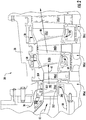
- the turbine nozzle 100 includes an inner band 200, an outer band 300 that is radially spaced from the inner band 200 and an airfoil 400 that extends in span from the inner band 200 to the outer band 300.
- the inner band 200 includes a gas side 202 and a back side 204 that is oriented radially inwardly from the gas side 202.
- the outer band 300 includes a gas side 302 and a back side 304 that is oriented radially outwardly from the gas side 302. As shown in FIGS.
- the gas side 302 of the outer band 300 and the gas side 202 of the inner band 200 define inner and outer radial flow boundaries for the stream of hot combustion gases 40 flowing at high velocity from the combustors 20 through the turbine 24.
- the airfoil 400 includes a leading edge portion 402, a trailing edge portion 404, a suction side wall 406 and a pressure side wall 408.
- FIG. 4 provides a cross sectioned top view of a portion of the turbine nozzle 100 as taken along section line 4-4 as shown in FIG. 3 and includes a portion of the airfoil 400 and the inner band 200 according to one embodiment of the present invention.
- the inner band 200 includes a forward wall 206 forward or upstream from the leading edge portion 402 of the airfoil 400, an aft wall 208 aft or downstream from the trailing edge portion 404, a suction side wall 210 and a pressure side wall 212.
- the turbine nozzle 100 includes and/or at least partially defines a primary cooling channel 102.
- the primary cooling channel 102 extends radially or substantially radially through the outer band 300, the airfoil 400 and the inner band 200.
- FIG. 5 provides a simplified cross sectional view of a portion of the inner band 200 as shown in FIG. 4 , according to at least one embodiment of the present invention.
- the inner band 200 defines a plurality of cooling channels 214 (shown in dashed lines in FIG. 4 ) and a coolant discharge plenum 216 ( FIG. 5 ) formed beneath a gas side surface 218 of the inner band 200 downstream from the cooling channels 214.
- the plurality of cooling channels 214 may be machined, cast or otherwise formed beneath the gas side surface 218 of the inner band 200.
- FIG. 4 provides a simplified cross sectional view of a portion of the inner band 200 as shown in FIG. 4 , according to at least one embodiment of the present invention.
- the inner band 200 defines a plurality of cooling channels 214 (shown in dashed lines in FIG. 4 ) and a coolant discharge plenum 216 ( FIG. 5 ) formed beneath a gas side surface 218 of the inner band 200 downstream from the cooling channels 214.
- the gas side surface 218 may be at least partially formed by one or more plates and/or a coating 220 which covers and/or seals the plurality of cooling channels 214.
- the plurality of cooling channels 214 may comprise multiple sets of cooling channels 214.
- the plurality of cooling channels 214 comprises, at least a first set of cooling channels 214(a) and a second set of cooling channels 214(b).
- the plurality of cooling channels 214 may be disposed beneath the gas side surface 218 in various locations depending on particular cooling requirements of the inner band 200. For example, as shown in FIG. 4 , at least some of the plurality of cooling channels 214 may be arranged or oriented so as to follow or substantially follow the curvature or profile of one or more of the leading edge portion 402, the suction side wall 406, the trialing edge portion 404 and the pressure side wall 408 of the airfoil 400. At least some of the cooling channels 214 may be disposed proximate to the suction side wall 210 or the aft wall 208 of the inner band 200 and/or proximate to the forward wall 206 of the inner band 200 between the suction side wall 210 and the pressure side wall 212.
- the inner band 200 defines at least one inlet passage 222 which provides for fluid communication between a coolant supply such as the compressor 16 ( FIG. 2 ) and the cooling channels 214.
- the inlet passage(s) 222 may extend through the back side 204 of the inner band 200.
- a coolant such as a portion of the compressed air 38 from the compressor 16 may be routed through the inlet passage(s) 222 and into the plurality of cooling channels 214.
- the first set of cooling channels 214(a) is in fluid communication with a first inlet passage 222(a) and the second set of cooling channels 214(b) is in fluid communication with a second inlet passage 222(b).
- At least one internal passage 224 defined within and/or by the inner band 200 provides for fluid communication between the cooling channels 214 or sets of cooling channels 214(a-b) and the coolant discharge plenum 216.
- the internal passage(s) 224 may form a network of internal passages 224 defined within the inner band 200 which provide for coolant flow from the plurality of cooling channels 214 into the coolant discharge plenum 216.
- FIG. 6 provides a top or radially inward view of a portion of the turbine nozzle 100 including the inner band 200 and a portion of the airfoil 400 as shown in the FIG. 4 , with the cooling channels 214 hidden below the gas side surface 218 according to one or more embodiments of the present invention.
- the coolant discharge plenum 216 (shown in dashed lines) may be positioned at various locations along the inner band 200 beneath the gas side surface 218.
- the coolant discharge plenum 216 may extend between the forward wall 206 and the aft wall 208 of the inner band 200, may be disposed between the suction side wall 406 of the airfoil 400 and the suction side wall 210 of the inner band 200, may be disposed between the pressure side wall 408 of the airfoil 400 and the pressure side wall 212 of the inner band 200 or may extend between the suction side wall 210 and the pressure side wall 212 of the inner band 200 forward of the leading edge portion 402 of the airfoil 400.
- the inner band 200 may define a plurality of coolant discharge plenums 216 disposed at various locations along the inner band 200.
- the coolant discharge plenum 216 is disposed and/or defined within the inner band 200 upstream from one or more coolant discharge ports 226.
- the coolant discharge port(s) 226 may extend through the gas side surface 218 to provide film cooling thereto.
- Discharge port(s) 226 may be disposed at any location along the gas side surface 218 depending, at least in part, on cooling requirements and/or positioning of coolant discharge plenum 216. For example, in one embodiment as shown in FIG.
- At least one coolant discharge port 226 may be formed or disposed along the gas side surface 218 of the inner band 200 upstream from the leading edge portion 402 of the airfoil 400. In one embodiment, at least one coolant discharge port 226 may be formed or disposed along the gas side surface 218 of the inner band 200 along a leading edge portion 228 of the inner band 200. In particular embodiments, as shown in FIG. 5 , at least one coolant discharge port 226 may extend through the suction side wall 210 of the inner band 200. In particular embodiments, as shown in FIG. 5 , at least one coolant discharge port 226 may extend through the pressure side wall 212 of the inner band 200.
- a coolant 230 such as compressed air 38 flows into the inlet passages 222 and flows through the cooling channels 214, thus providing convection cooling to the gas side surface 218 of the inner band.
- Spent coolant 232 is then routed through the internal passages 224 to the coolant discharge plenum 216 which is at a lower pressure than the cooling channels 214.
- the spent coolant 232 is then routed through the coolant discharge port(s) 226, for example, to provide film cooling to the gas side surface 218 of the inner band 200 and to cool and/or to help form a hot gas seal between adjacent inner bands 200 of adjacent turbine nozzles 100.
- FIG. 7 provides a cross sectioned top view of a portion of the turbine nozzle 100 as taken along section line 7-7 as shown in FIG. 3 and includes a portion of the airfoil 400 and the outer band 300 according to one embodiment of the present invention.
- the outer band 300 includes a forward wall 306 forward or upstream from the leading edge portion 402 of the airfoil 400, an aft wall 308 aft or downstream from the trailing edge portion 404, a suction side wall 310 and a pressure side wall 312.
- the primary cooling channel 102 extends radially or substantially radially through the inner band 200, the airfoil 400 and the outer band 300.
- FIG. 8 provides a simplified cross sectional view of a portion of the outer band 300 as shown in FIG. 7 , according to at least one embodiment of the present invention.
- the outer band 300 defines a plurality of cooling channels 314 (shown in dashed lines in FIG. 7 ) and a coolant discharge plenum 316 ( FIG. 8 ) formed beneath a gas side surface 318 of the outer band 300 downstream from the cooling channels 314.
- the plurality of cooling channels 314 may be machined, cast or otherwise formed beneath the gas side surface 318 of the outer band 300.
- FIG. 8 provides a simplified cross sectional view of a portion of the outer band 300 as shown in FIG. 7 , according to at least one embodiment of the present invention.
- the outer band 300 defines a plurality of cooling channels 314 (shown in dashed lines in FIG. 7 ) and a coolant discharge plenum 316 ( FIG. 8 ) formed beneath a gas side surface 318 of the outer band 300 downstream from the cooling channels 314.
- the gas side surface 318 may be at least partially formed by one or more plates and/or a coating 320 which covers and/or seals the plurality of cooling channels 314.
- the plurality of cooling channels 314 may comprise multiple sets of cooling channels 314.
- the plurality of cooling channels 314 comprises, at least a first set of cooling channels 314(a) and a second set of cooling channels 314(b).
- the plurality of cooling channels 314 may be disposed beneath the gas side surface 318 in various locations depending on particular cooling requirements of the outer band 300. For example, as shown in FIG. 7 , at least some of the plurality of cooling channels 314 may be arranged or oriented so as to follow or substantially follow the curvature or profile of one or more of the leading edge portion 402, the suction side wall 406, the trialing edge portion 404 and the pressure side wall 408 of the airfoil 400. At least some of the cooling channels 314 may be disposed proximate to the suction side wall 310 or the aft wall 308 of the outer band 300 and/or proximate to the forward wall 306 of the outer band 300 between the suction side wall 310 and the pressure side wall 312.
- the outer band 300 defines at least one inlet passage 322 which provides for fluid communication between a coolant supply such as the compressor 16 ( FIG. 2 ) and the cooling channels 314.
- the inlet passage(s) 322 may extend through the back side 304 of the outer band 300.
- a coolant such as a portion of the compressed air 38 from the compressor 16 may be routed through the inlet passage(s) 322 and into the plurality of cooling channels 314.
- the first set of cooling channels 314(a) is in fluid communication with a first inlet passage 322(a) and the second set of cooling channels 314(b) is in fluid communication with a second inlet passage 322(b).
- At least one internal passage 324 defined within and/or by the outer band 300 provides for fluid communication between the cooling channels 314 or sets of cooling channels 314(a-b) and the coolant discharge plenum 316.
- the internal passage(s) 324 may form a network of internal passages 324 defined within the outer band 300 which provide for coolant flow from the plurality of cooling channels 314 into the coolant discharge plenum 316.
- FIG. 9 provides a top or radially inward view of a portion of the turbine nozzle 100 including the outer band 300 and a portion of the airfoil 400 as shown in FIG. 7 , with the cooling channels 314 hidden below the gas side surface 318 according to one or more embodiments of the present invention.
- the coolant discharge plenum 316 (shown in dashed lines) may be positioned at various locations along the outer band 300 beneath the gas side surface 318.
- the coolant discharge plenum 316 may extend between the forward wall 306 and the aft wall 308 of the outer band 300, may be disposed between the suction side wall 406 of the airfoil 400 and the suction side wall 310 of the outer band 300, may be disposed between the pressure side wall 408 of the airfoil 400 and the pressure side wall 312 of the outer band 300 or may extend between the suction side wall 310 and the pressure side wall 312 of the outer band 300 forward of the leading edge portion 402 of the airfoil 400.
- the outer band 300 may define a plurality of coolant discharge plenums 316 disposed at various locations along the outer band 300.
- the coolant discharge plenum 316 is disposed and/or defined within the outer band 300 upstream from one or more coolant discharge ports 326.
- the coolant discharge port(s) 326 may extend through the gas side surface 318 to provide film cooling thereto.
- Discharge port(s) 326 may be disposed at any location along the gas side surface 318 depending, at least in part, on cooling requirements and/or positioning of coolant discharge plenum 316. For example, in one embodiment as shown in FIG.
- At least one coolant discharge port 326 may be formed or disposed along the gas side surface 318 of the outer band 300 upstream from the leading edge portion 402 of the airfoil 400. In one embodiment, at least one coolant discharge port 326 may be formed or disposed along the gas side surface 318 of the outer band 300 along a leading edge portion 328 of the outer band 300. In particular embodiments, as shown in FIG. 8 , at least one coolant discharge port 326 may extend through the suction side wall 310 of the outer band 300. In particular embodiments, as shown in FIG. 8 , at least one coolant discharge port 326 may extend through the pressure side wall 312 of the outer band 300.
- both the inner band 200 and the outer band 300 comprise inlet passages 222, 322, cooling channels 214, 314, internal passages 224, 324, coolant discharge plenums 216, 316 and cooling discharge ports 226, 326 respectfully.
- a coolant 330 such as compressed air 38 flows into the inlet passages 322, flows through the cooling channels 314, thus providing convection cooling to the gas side surface 318 of the outer band 300.
- Spent coolant 332 is then routed through the internal passages 324 to the coolant discharge plenum 316 which is at a lower pressure than the cooling channels 314.
- the spent coolant 332 is then routed through the coolant discharge port(s) 326, for example, to provide film cooling to the gas side surface 318 of the outer band 300 and to cool and/or to help form a hot gas seal between adjacent outer bands 300 of adjacent turbine nozzles 100.
Landscapes
- Engineering & Computer Science (AREA)
- Mechanical Engineering (AREA)
- General Engineering & Computer Science (AREA)
- Turbine Rotor Nozzle Sealing (AREA)
Abstract
Description
- The present invention generally relates to a turbine nozzle for a gas turbine. More particularly, this invention relates to a turbine nozzle with cooling channels and a coolant discharge plenum defined within an inner or outer band of the turbine nozzle.
- A gas turbine, such as an industrial, aircraft or marine gas turbine generally includes, in serial flow order, a compressor, a combustor and a turbine. The turbine has multiple stages with each stage including a row of turbine nozzles and an adjacent row of turbine rotor blades disposed downstream from the turbine nozzles. The turbine nozzles are held stationary within the turbine and the turbine rotor blades rotate with a rotor shaft. The various turbine stages define a hot gas path through the turbine.
- During operation, the compressor provides compressed air to the combustor. The compressed air is mixed with fuel and burned in a combustion chamber or reaction zone defined within the combustor to produce a high velocity stream of hot gas. The hot gas flows from the combustor into the hot gas path of the turbine via a turbine inlet. As the hot gas flows through each successive stage, kinetic energy from the high velocity hot gas is transferred to the rows of turbine rotor blades, thus causing the rotor shaft to rotate and produce mechanical work.
- Turbine efficiency may be related, at least in part, to the temperature of the hot gas flowing through the turbine hot gas path. For example, the higher the temperature of the hot gas, the greater the overall efficiency of the turbine. The maximum temperature of the hot gas is limited, at least in part, by material properties of the various turbine components such as the turbine nozzles and turbine rotor blades and by the effectiveness of various cooling circuits and a cooling medium that circulates through the cooling circuits to provide cooling to the various turbine components.
- Turbine nozzles generally include an airfoil that extends in span between an inner band or shroud and an outer band or shroud. The inner band and the outer band define inner and outer flow boundaries of the hot gas path and are exposed to the hot gases. The inner and/or outer bands may be cooled by passing a cooling medium such as compressed air through a central or core cooling channel that extends radially through the airfoil portion of the turbine nozzle. A portion of the cooling medium flows through various film holes defined along the airfoil, thus providing film cooling to the airfoil.
- Aspects and advantages of the invention are set forth below in the following description, or may be obvious from the description, or may be learned through practice of the invention.
- One embodiment of the present invention is a turbine nozzle. The turbine nozzle includes an airfoil that extends in span from an inner band to an outer band where the inner band and the outer band define inner and outer flow boundaries of the turbine nozzle. The inner band defines a plurality of cooling channels and a coolant discharge plenum formed beneath a gas side surface of the inner band where the coolant discharge plenum is in fluid communication with the cooling channels. The coolant discharge plenum is formed within the inner band downstream from the cooling channels and upstream from a plurality of coolant discharge ports.
- Another embodiment of the present invention is a turbine nozzle. The turbine nozzle includes an airfoil that extends in span from an inner band to an outer band where the inner band and the outer band define inner and outer flow boundaries of the turbine nozzle. The outer band defines a plurality of cooling channels and a coolant discharge plenum formed beneath a gas side surface of the outer band where the coolant discharge plenum is in fluid communication with the cooling channels. The coolant discharge plenum is formed within the outer band downstream from the cooling channels and upstream from a plurality of coolant discharge ports.
- Those of ordinary skill in the art will better appreciate the features and aspects of such embodiments, and others, upon review of the specification.
- A full and enabling disclosure of the present invention is set forth more particularly in the remainder of the specification, including reference to the accompanying figures, in which:
-
FIG. 1 is a schematic view of an exemplary gas turbine as may incorporate various embodiments of the present invention; -
FIG. 2 is a cross sectioned side view of an exemplary turbine section of a gas turbine as may incorporated in various embodiments of the present invention; -
FIG. 3 is a perspective side view of an exemplary turbine nozzle as may incorporate one or more embodiments of the present invention; -
FIG. 4 is a cross sectioned top view of a portion of the turbine nozzle including an inner band as shown inFIG. 3 taken along section line 4-4, according to at least one embodiment of the present invention; -
FIG. 5 is an enlarged simplified cross sectional side view of a portion of the inner band as shown inFIG. 4 , according to one or more embodiments of the present invention; -
FIG. 6 is a top view or the turbine nozzle as shown inFIG. 4 , according to at least one embodiment of the present invention; -
FIG. 7 is a cross sectioned top view of a portion of the turbine nozzle including an inner band as shown inFIG. 3 taken along section line 7-7, according to at least one embodiment of the present invention; -
FIG. 8 is an enlarged simplified cross sectional side view of a portion of the inner band as shown inFIG. 7 , according to one or more embodiments of the present invention; and -
FIG. 9 is a top view or the turbine nozzle as shown inFIG. 7 , according to at least one embodiment of the present invention. - Reference will now be made in detail to present embodiments of the invention, one or more examples of which are illustrated in the accompanying drawings. The detailed description uses numerical and letter designations to refer to features in the drawings. Like or similar designations in the drawings and description have been used to refer to like or similar parts of the invention.
- As used herein, the terms "first", "second", and "third" may be used interchangeably to distinguish one component from another and are not intended to signify location or importance of the individual components. The terms "upstream" and "downstream" refer to the relative direction with respect to fluid flow in a fluid pathway. For example, "upstream" refers to the direction from which the fluid flows, and "downstream" refers to the direction to which the fluid flows. The term "radially" refers to the relative direction that is substantially perpendicular to an axial centerline of a particular component, and the term "axially" refers to the relative direction that is substantially parallel and/or coaxially aligned to an axial centerline of a particular component.
- The terminology used herein is for the purpose of describing particular embodiments only and is not intended to be limiting of the invention. As used herein, the singular forms "a", "an" and "the" are intended to include the plural forms as well, unless the context clearly indicates otherwise. It will be further understood that the terms "comprises" and/or "comprising," when used in this specification, specify the presence of stated features, integers, steps, operations, elements, and/or components, but do not preclude the presence or addition of one or more other features, integers, steps, operations, elements, components, and/or groups thereof.
- Each example is provided by way of explanation of the invention, not limitation of the invention. In fact, it will be apparent to those skilled in the art that modifications and variations can be made in the present invention without departing from the scope or spirit thereof. For instance, features illustrated or described as part of one embodiment may be used on another embodiment to yield a still further embodiment. Thus, it is intended that the present invention covers such modifications and variations as come within the scope of the appended claims and their equivalents.
- Although exemplary embodiments of the present invention will be described generally in the context of a turbine nozzle for a land based power generating gas turbine for purposes of illustration, one of ordinary skill in the art will readily appreciate that embodiments of the present invention may be applied to any style or type of gas turbine and are not limited to land based power generating gas turbines unless specifically recited in the claims.
- Referring now to the drawings,
FIG. 1 illustrates a schematic of anexemplary gas turbine 10 as may incorporate various embodiments of the present invention. As shown, thegas turbine 10 generally includes acompressor section 12 having aninlet 14 disposed at an upstream end of anaxial compressor 16. Thegas turbine 10 further includes acombustion section 18 having one ormore combustors 20 positioned downstream from thecompressor 16 and aturbine section 22 including aturbine 24 such as an expansion turbine that is disposed downstream from thecombustion section 18. Ashaft 26 extends axially through thecompressor 16 and theturbine 24 along anaxial centerline 28 of thegas turbine 10. -
FIG. 2 provides a cross sectioned side view of anexemplary turbine 24 as may incorporate various embodiments of the present invention. As shown inFIG. 2 , theturbine 24 may includemultiple turbine stages 30. For example, theturbine 24 may include threeturbine stages 30 including a first stage 30(a), second stage 30(b) and third stage 30(c). The total number ofturbine stages 30 may be more or less than three and embodiments of the present invention should not be limited to three turbine stages unless otherwise recited in the claims. - As shown in
FIG. 2 , each stage 30(a-c) includes, in serial flow order, a corresponding row of turbine nozzles 32(a), 32(b) and 32(c) and a corresponding row of turbine rotor blades 34(a), 34(b) and 34(c) axially spaced along the shaft 26 (FIG. 1 ). A casing orshell 36 circumferentially surrounds each stage 30(a-c) of the turbine nozzles 32(a-c) and the turbine rotor blades 34(a-c). The turbine nozzles 32(a-c) remain stationary relative to the turbine rotor blades 34(a-c) during operation of thegas turbine 10. For example, theturbine nozzles 32 may be connected to thecasing 36 or to a nozzle ring (not shown). - In operation, as shown in
FIGS. 1 and2 collectively,compressed air 38 from thecompressor 16 is provided to thecombustors 20 where it is mixed with fuel and burned to provide a stream ofhot combustion gases 40 that flows from thecombustors 20 into theturbine 24. At least a portion of thecompressed air 38 may be used as a cooling medium for cooling the various components of the turbine such as the turbine nozzles 32(a-c) and the turbine rotor blades 34(a-c). -
FIG. 3 provides a perspective view of anexemplary turbine nozzle 100 as may be incorporated into theturbine 24 as shown inFIG. 2 and as may incorporate various embodiments of the present invention.Turbine nozzle 100 may correspond with or be installed in place of any of turbine nozzles 32(a-c). In particular embodiments,turbine nozzle 100 corresponds with turbine nozzle 32(a) of the first stage 30(a) which may also be known in the industry as a stage one nozzle or S1N. - As shown in
FIG. 3 , theturbine nozzle 100 includes aninner band 200, anouter band 300 that is radially spaced from theinner band 200 and anairfoil 400 that extends in span from theinner band 200 to theouter band 300. Theinner band 200 includes agas side 202 and aback side 204 that is oriented radially inwardly from thegas side 202. Theouter band 300 includes agas side 302 and aback side 304 that is oriented radially outwardly from thegas side 302. As shown inFIGS. 2 and3 collectively, thegas side 302 of theouter band 300 and thegas side 202 of theinner band 200 define inner and outer radial flow boundaries for the stream ofhot combustion gases 40 flowing at high velocity from thecombustors 20 through theturbine 24. As shown inFIG. 3 , theairfoil 400 includes aleading edge portion 402, a trailingedge portion 404, asuction side wall 406 and apressure side wall 408. -
FIG. 4 provides a cross sectioned top view of a portion of theturbine nozzle 100 as taken along section line 4-4 as shown inFIG. 3 and includes a portion of theairfoil 400 and theinner band 200 according to one embodiment of the present invention. As shown inFIG. 4 , theinner band 200 includes aforward wall 206 forward or upstream from theleading edge portion 402 of theairfoil 400, anaft wall 208 aft or downstream from the trailingedge portion 404, asuction side wall 210 and apressure side wall 212. In particular arrangements, theturbine nozzle 100 includes and/or at least partially defines aprimary cooling channel 102. In one embodiment, theprimary cooling channel 102 extends radially or substantially radially through theouter band 300, theairfoil 400 and theinner band 200. -
FIG. 5 provides a simplified cross sectional view of a portion of theinner band 200 as shown inFIG. 4 , according to at least one embodiment of the present invention. In one embodiment, as shown inFIGS. 4 and5 collectively, theinner band 200 defines a plurality of cooling channels 214 (shown in dashed lines inFIG. 4 ) and a coolant discharge plenum 216 (FIG. 5 ) formed beneath agas side surface 218 of theinner band 200 downstream from the coolingchannels 214. The plurality of coolingchannels 214 may be machined, cast or otherwise formed beneath thegas side surface 218 of theinner band 200. In particular embodiments, as shown inFIG. 5 , thegas side surface 218 may be at least partially formed by one or more plates and/or acoating 220 which covers and/or seals the plurality of coolingchannels 214. As shown inFIGS. 4 and5 , the plurality of coolingchannels 214 may comprise multiple sets of coolingchannels 214. For example, in one embodiment, as shown inFIG. 5 , the plurality of coolingchannels 214 comprises, at least a first set of cooling channels 214(a) and a second set of cooling channels 214(b). - The plurality of cooling
channels 214 may be disposed beneath thegas side surface 218 in various locations depending on particular cooling requirements of theinner band 200. For example, as shown inFIG. 4 , at least some of the plurality of coolingchannels 214 may be arranged or oriented so as to follow or substantially follow the curvature or profile of one or more of theleading edge portion 402, thesuction side wall 406, the trialingedge portion 404 and thepressure side wall 408 of theairfoil 400. At least some of the coolingchannels 214 may be disposed proximate to thesuction side wall 210 or theaft wall 208 of theinner band 200 and/or proximate to theforward wall 206 of theinner band 200 between thesuction side wall 210 and thepressure side wall 212. - In particular embodiments, as shown in
FIG. 5 , theinner band 200 defines at least oneinlet passage 222 which provides for fluid communication between a coolant supply such as the compressor 16 (FIG. 2 ) and the coolingchannels 214. In particular embodiments, the inlet passage(s) 222 may extend through theback side 204 of theinner band 200. During operation of thegas turbine 10, a coolant such as a portion of thecompressed air 38 from thecompressor 16 may be routed through the inlet passage(s) 222 and into the plurality of coolingchannels 214. In one embodiment, the first set of cooling channels 214(a) is in fluid communication with a first inlet passage 222(a) and the second set of cooling channels 214(b) is in fluid communication with a second inlet passage 222(b). - In various embodiments, as shown in
FIG. 5 , at least one internal passage 224 defined within and/or by theinner band 200 provides for fluid communication between the coolingchannels 214 or sets of cooling channels 214(a-b) and thecoolant discharge plenum 216. The internal passage(s) 224 may form a network of internal passages 224 defined within theinner band 200 which provide for coolant flow from the plurality of coolingchannels 214 into thecoolant discharge plenum 216. -
FIG. 6 provides a top or radially inward view of a portion of theturbine nozzle 100 including theinner band 200 and a portion of theairfoil 400 as shown in theFIG. 4 , with the coolingchannels 214 hidden below thegas side surface 218 according to one or more embodiments of the present invention. As shown inFIG. 6 , the coolant discharge plenum 216 (shown in dashed lines) may be positioned at various locations along theinner band 200 beneath thegas side surface 218. For example, thecoolant discharge plenum 216 may extend between theforward wall 206 and theaft wall 208 of theinner band 200, may be disposed between thesuction side wall 406 of theairfoil 400 and thesuction side wall 210 of theinner band 200, may be disposed between thepressure side wall 408 of theairfoil 400 and thepressure side wall 212 of theinner band 200 or may extend between thesuction side wall 210 and thepressure side wall 212 of theinner band 200 forward of theleading edge portion 402 of theairfoil 400. In particular embodiments, theinner band 200 may define a plurality ofcoolant discharge plenums 216 disposed at various locations along theinner band 200. - In various embodiments, as shown in
FIG. 5 , thecoolant discharge plenum 216 is disposed and/or defined within theinner band 200 upstream from one or morecoolant discharge ports 226. In particular embodiments, as shown inFIGS. 5 and 6 , the coolant discharge port(s) 226 may extend through thegas side surface 218 to provide film cooling thereto. Discharge port(s) 226 may be disposed at any location along thegas side surface 218 depending, at least in part, on cooling requirements and/or positioning ofcoolant discharge plenum 216. For example, in one embodiment as shown inFIG. 6 , at least onecoolant discharge port 226 may be formed or disposed along thegas side surface 218 of theinner band 200 upstream from theleading edge portion 402 of theairfoil 400. In one embodiment, at least onecoolant discharge port 226 may be formed or disposed along thegas side surface 218 of theinner band 200 along aleading edge portion 228 of theinner band 200. In particular embodiments, as shown inFIG. 5 , at least onecoolant discharge port 226 may extend through thesuction side wall 210 of theinner band 200. In particular embodiments, as shown inFIG. 5 , at least onecoolant discharge port 226 may extend through thepressure side wall 212 of theinner band 200. - In operation, a
coolant 230 such ascompressed air 38 flows into theinlet passages 222 and flows through the coolingchannels 214, thus providing convection cooling to thegas side surface 218 of the inner band.Spent coolant 232 is then routed through the internal passages 224 to thecoolant discharge plenum 216 which is at a lower pressure than the coolingchannels 214. The spentcoolant 232 is then routed through the coolant discharge port(s) 226, for example, to provide film cooling to thegas side surface 218 of theinner band 200 and to cool and/or to help form a hot gas seal between adjacentinner bands 200 ofadjacent turbine nozzles 100. -
FIG. 7 provides a cross sectioned top view of a portion of theturbine nozzle 100 as taken along section line 7-7 as shown inFIG. 3 and includes a portion of theairfoil 400 and theouter band 300 according to one embodiment of the present invention. As shown inFIG. 7 , theouter band 300 includes aforward wall 306 forward or upstream from theleading edge portion 402 of theairfoil 400, anaft wall 308 aft or downstream from the trailingedge portion 404, asuction side wall 310 and apressure side wall 312. In one embodiment, theprimary cooling channel 102 extends radially or substantially radially through theinner band 200, theairfoil 400 and theouter band 300. -
FIG. 8 provides a simplified cross sectional view of a portion of theouter band 300 as shown inFIG. 7 , according to at least one embodiment of the present invention. In one embodiment, as shown inFIGS. 7 and8 collectively, theouter band 300 defines a plurality of cooling channels 314 (shown in dashed lines inFIG. 7 ) and a coolant discharge plenum 316 (FIG. 8 ) formed beneath agas side surface 318 of theouter band 300 downstream from the coolingchannels 314. The plurality of coolingchannels 314 may be machined, cast or otherwise formed beneath thegas side surface 318 of theouter band 300. In particular embodiments, as shown inFIG. 8 , thegas side surface 318 may be at least partially formed by one or more plates and/or acoating 320 which covers and/or seals the plurality of coolingchannels 314. As shown inFIGS. 7 and8 , the plurality of coolingchannels 314 may comprise multiple sets of coolingchannels 314. For example, in one embodiment, as shown inFIG. 8 , the plurality of coolingchannels 314 comprises, at least a first set of cooling channels 314(a) and a second set of cooling channels 314(b). - The plurality of cooling
channels 314 may be disposed beneath thegas side surface 318 in various locations depending on particular cooling requirements of theouter band 300. For example, as shown inFIG. 7 , at least some of the plurality of coolingchannels 314 may be arranged or oriented so as to follow or substantially follow the curvature or profile of one or more of theleading edge portion 402, thesuction side wall 406, the trialingedge portion 404 and thepressure side wall 408 of theairfoil 400. At least some of the coolingchannels 314 may be disposed proximate to thesuction side wall 310 or theaft wall 308 of theouter band 300 and/or proximate to theforward wall 306 of theouter band 300 between thesuction side wall 310 and thepressure side wall 312. - In particular embodiments, as shown in
FIG. 8 , theouter band 300 defines at least oneinlet passage 322 which provides for fluid communication between a coolant supply such as the compressor 16 (FIG. 2 ) and the coolingchannels 314. In particular embodiments, the inlet passage(s) 322 may extend through theback side 304 of theouter band 300. During operation of thegas turbine 10, a coolant such as a portion of thecompressed air 38 from thecompressor 16 may be routed through the inlet passage(s) 322 and into the plurality of coolingchannels 314. In one embodiment, the first set of cooling channels 314(a) is in fluid communication with a first inlet passage 322(a) and the second set of cooling channels 314(b) is in fluid communication with a second inlet passage 322(b). - In various embodiments, as shown in
FIG. 8 , at least one internal passage 324 defined within and/or by theouter band 300 provides for fluid communication between the coolingchannels 314 or sets of cooling channels 314(a-b) and thecoolant discharge plenum 316. The internal passage(s) 324 may form a network of internal passages 324 defined within theouter band 300 which provide for coolant flow from the plurality of coolingchannels 314 into thecoolant discharge plenum 316. -
FIG. 9 provides a top or radially inward view of a portion of theturbine nozzle 100 including theouter band 300 and a portion of theairfoil 400 as shown inFIG. 7 , with the coolingchannels 314 hidden below thegas side surface 318 according to one or more embodiments of the present invention. In various embodiments, as shown inFIG. 9 , the coolant discharge plenum 316 (shown in dashed lines) may be positioned at various locations along theouter band 300 beneath thegas side surface 318. For example, thecoolant discharge plenum 316 may extend between theforward wall 306 and theaft wall 308 of theouter band 300, may be disposed between thesuction side wall 406 of theairfoil 400 and thesuction side wall 310 of theouter band 300, may be disposed between thepressure side wall 408 of theairfoil 400 and thepressure side wall 312 of theouter band 300 or may extend between thesuction side wall 310 and thepressure side wall 312 of theouter band 300 forward of theleading edge portion 402 of theairfoil 400. In particular embodiments, theouter band 300 may define a plurality ofcoolant discharge plenums 316 disposed at various locations along theouter band 300. - In various embodiments, as shown in
FIG. 8 , thecoolant discharge plenum 316 is disposed and/or defined within theouter band 300 upstream from one or morecoolant discharge ports 326. In particular embodiments, as shown inFIGS. 8 and 9 , the coolant discharge port(s) 326 may extend through thegas side surface 318 to provide film cooling thereto. Discharge port(s) 326 may be disposed at any location along thegas side surface 318 depending, at least in part, on cooling requirements and/or positioning ofcoolant discharge plenum 316. For example, in one embodiment as shown inFIG. 9 , at least onecoolant discharge port 326 may be formed or disposed along thegas side surface 318 of theouter band 300 upstream from theleading edge portion 402 of theairfoil 400. In one embodiment, at least onecoolant discharge port 326 may be formed or disposed along thegas side surface 318 of theouter band 300 along aleading edge portion 328 of theouter band 300. In particular embodiments, as shown inFIG. 8 , at least onecoolant discharge port 326 may extend through thesuction side wall 310 of theouter band 300. In particular embodiments, as shown inFIG. 8 , at least onecoolant discharge port 326 may extend through thepressure side wall 312 of theouter band 300. In particular embodiments, both theinner band 200 and theouter band 300 compriseinlet passages channels coolant discharge plenums discharge ports - In operation, a
coolant 330 such ascompressed air 38 flows into theinlet passages 322, flows through the coolingchannels 314, thus providing convection cooling to thegas side surface 318 of theouter band 300.Spent coolant 332 is then routed through the internal passages 324 to thecoolant discharge plenum 316 which is at a lower pressure than the coolingchannels 314. The spentcoolant 332 is then routed through the coolant discharge port(s) 326, for example, to provide film cooling to thegas side surface 318 of theouter band 300 and to cool and/or to help form a hot gas seal between adjacentouter bands 300 ofadjacent turbine nozzles 100. - This written description uses examples to disclose the invention and also to enable any person skilled in the art to practice the invention, including making and using any devices or systems and performing any incorporated methods. The patentable scope of the invention is defined by the claims, and may include other examples that occur to those skilled in the art. Such other and examples are intended to be within the scope of the claims if they include structural elements that do not differ from the literal language of the claims, or if they include equivalent structural elements with insubstantial differences from the literal language of the claims.
- Various aspects and embodiments of the present invention are defined by the following numbered clauses:
- 1. A turbine nozzle, comprising:
- an airfoil that extends in span from an inner band to an outer band, wherein the inner band and the outer band define inner and outer flow boundaries of the turbine nozzle;
- wherein the inner band defines a plurality of cooling channels and a coolant discharge plenum in fluid communication with the cooling channels, wherein the plurality of cooling channels and the coolant discharge plenum are formed beneath a gas side surface of the inner band, wherein the coolant discharge plenum is formed downstream from the cooling channels and upstream from at least one coolant discharge port.
- 2. The turbine nozzle as in clause 1, wherein the plurality of cooling channels comprises a first set of cooling channels and a second set of cooling channels, wherein the first set of cooling channels and the second set of cooling channels are downstream from a coolant supply and upstream from the coolant discharge plenum.
- 3. The turbine nozzle as in any preceding clause, wherein the coolant discharge plenum extends between a forward wall and an aft wall of the inner band and is disposed between a suction side wall of the airfoil and a suction side wall of the inner band.
- 4. The turbine nozzle as in any preceding clause, wherein the coolant discharge plenum extends between a forward wall and an aft wall of the inner band and is disposed between a pressure side wall of the airfoil and a pressure side wall of the inner band.
- 5. The turbine nozzle as in any preceding clause, wherein the coolant discharge plenum extends between a suction side wall and a pressure side wall of the inner band forward of a leading edge portion of the airfoil.
- 6. The turbine nozzle as in any preceding clause, wherein at least one coolant discharge port of the at least one coolant discharge port is formed along the gas side surface of the inner band.
- 7. The turbine nozzle as in any preceding clause, wherein at least one coolant discharge port of the at least one coolant discharge port is formed along the gas side surface of the inner band upstream from a leading edge portion of the airfoil.
- 8. The turbine nozzle as in any preceding clause, wherein at least one coolant discharge port of the at least one coolant discharge port is formed along the gas side surface of the inner band along a leading edge portion of the inner band.
- 9. The turbine nozzle as in any preceding clause, wherein at least one coolant discharge port of the at least one coolant discharge port is formed along a pressure side of the inner band.
- 10. The turbine nozzle as in any preceding clause, wherein at least one coolant discharge port of the at least one coolant discharge port is formed along a suction side of the inner band.
- 11. A turbine nozzle, comprising:
- an airfoil that extends in span from an inner band to an outer band, wherein the inner band and the outer band define inner and outer flow boundaries of the turbine nozzle;
- wherein the outer band defines a plurality of cooling channels and a coolant discharge plenum in fluid communication with the cooling channels, wherein the plurality of cooling channels and the coolant discharge plenum are formed beneath a gas side surface of the outer band, wherein the coolant discharge plenum is formed downstream from the cooling channels and upstream from at least one coolant discharge port.
- 12. The turbine nozzle as in any preceding clause, wherein the plurality of cooling channels comprises a first set of cooling channels and a second set of cooling channels, wherein the first set of cooling channels and the second set of cooling channels are downstream from a coolant supply and upstream from the coolant discharge plenum.
- 13. The turbine nozzle as in any preceding clause, wherein the coolant discharge plenum extends between a forward wall and an aft wall of the outer band and is disposed between a suction side wall of the airfoil and a suction side wall of the outer band.
- 14. The turbine nozzle as in any preceding clause, wherein the coolant discharge plenum extends between a forward wall and an aft wall of the outer band and is disposed between a pressure side wall of the airfoil and a pressure side wall of the outer band.
- 15. The turbine nozzle as in any preceding clause, wherein the coolant discharge plenum extends between a suction side wall and a pressure side wall of the outer band forward of a leading edge portion of the airfoil.
- 16. The turbine nozzle as in any preceding clause, wherein at least one coolant discharge port of the at least one coolant discharge port is formed along the gas side surface of the outer band.
- 17. The turbine nozzle as in any preceding clause, wherein at least one coolant discharge port of the at least one coolant discharge port is formed along the gas side surface of the outer band upstream from a leading edge portion of the airfoil.
- 18. The turbine nozzle as in any preceding clause, wherein at least one coolant discharge port of the at least one coolant discharge port is formed along the gas side surface of the outer band along a leading edge portion of the outer band.
- 19. The turbine nozzle as in any preceding clause, wherein at least one coolant discharge port of the at least one coolant discharge port is formed along a pressure side of the outer band.
- 20. The turbine nozzle as in any preceding clause, wherein at least one coolant discharge port of the at least one coolant discharge port is formed along a suction side of the outer band.
Claims (15)
- A turbine nozzle (100), comprising:an airfoil (400) that extends in span from an inner band (200) to an outer band (300), wherein the inner band (200) and the outer band (300) define inner and outer flow boundaries of the turbine nozzle (100);wherein the inner band (200) defines a plurality of cooling channels (214) and a coolant discharge plenum (216) in fluid communication with the cooling channels (214), wherein the plurality of cooling channels (214) and the coolant discharge plenum (216) are formed beneath a gas side surface (218) of the inner band (200), wherein the coolant discharge plenum (216) is formed downstream from the cooling channels (214) and upstream from at least one coolant discharge port (226).
- The turbine nozzle (100) as in claim 1, wherein the plurality of cooling channels (214) comprises a first set of cooling channels (214a) and a second set of cooling channels (214b), wherein the first set of cooling channels (214a) and the second set of cooling channels (214b) are downstream from a coolant supply and upstream from the coolant discharge plenum (216).
- The turbine nozzle (100) as in claim 1 or 2, wherein the coolant discharge plenum (216) extends between a forward wall (206) and an aft wall (208) of the inner band (200) and is disposed between a suction side (406) wall of the airfoil (400) and a suction side (210) wall of the inner band (200).
- The turbine nozzle (100) as in claim 1 or 2, wherein the coolant discharge plenum (216) extends between a forward wall (206) and an aft wall (208) of the inner band (200) and is disposed between a pressure side wall (408) of the airfoil (400) and a pressure side wall (212) of the inner band (200).
- The turbine nozzle (100) as in claim 1 or 2, wherein the coolant discharge plenum (216) extends between a suction side (210) wall and a pressure side wall (212) of the inner band (200) forward of a leading edge portion (402) of the airfoil (400).
- The turbine nozzle (100) as in any preceding claim, wherein at least one coolant discharge port (226) of the at least one coolant discharge port (226) is formed along the gas side surface (218) of the inner band (200).
- The turbine nozzle (100) as in any preceding claim, wherein at least one coolant discharge port (226) of the at least one coolant discharge port (226) is formed along the gas side surface (218) of the inner band (200) upstream from a leading edge portion (402) of the airfoil (400).
- The turbine nozzle (100) as in any preceding claim, wherein at least one coolant discharge port (226) of the at least one coolant discharge port (226) is formed along the gas side surface (218) of the inner band (200) along a leading edge portion (228) of the inner band (200).
- The turbine nozzle (100) as in any preceding claim, wherein at least one coolant discharge port (226) of the at least one coolant discharge port (226) is formed along a pressure side of the inner band (200).
- The turbine nozzle (100) as in any preceding claim, wherein at least one coolant discharge port (226) of the at least one coolant discharge port (226) is formed along a suction side (210) of the inner band (200).
- A turbine nozzle (100), comprising:an airfoil (400) that extends in span from an inner band (200) to an outer band (300), wherein the inner band (200) and the outer band (300) define inner and outer flow boundaries of the turbine nozzle (100);wherein the outer band (300) defines a plurality of cooling channels (314) and a coolant discharge plenum (316) in fluid communication with the cooling channels (314), wherein the plurality of cooling channels (314) and the coolant discharge plenum (316) are formed beneath a gas side surface (318) of the outer band (300), wherein the coolant discharge plenum (316) is formed downstream from the cooling channels (314) and upstream from at least one coolant discharge port (326).
- The turbine nozzle (100) as in claim 11, wherein the plurality of cooling channels (314) comprises a first set of cooling channels (314a) and a second set of cooling channels (314b), wherein the first set of cooling channels (314a) and the second set of cooling channels (314b) are downstream from a coolant supply and upstream from the coolant discharge plenum (316).
- The turbine nozzle (100) as in claim 11 or 12, wherein the coolant discharge plenum (316) extends between a suction side (310) wall and a pressure side wall (312) of the outer band (300) forward of a leading edge portion (402) of the airfoil (400).
- The turbine nozzle (100) as in claim 11, 12 or 13, wherein at least one coolant discharge port (326) of the at least one coolant discharge port (326) is formed along the gas side surface (318) of the outer band (300).
- The turbine nozzle (100) as in any of claims 11 to 14, wherein at least one coolant discharge port (326) of the at least one coolant discharge port (326) is formed along the gas side surface (318) of the outer band (300) upstream from a leading edge portion (402) of the airfoil (400).
Applications Claiming Priority (1)
| Application Number | Priority Date | Filing Date | Title |
|---|---|---|---|
| US14/880,575 US9995172B2 (en) | 2015-10-12 | 2015-10-12 | Turbine nozzle with cooling channel coolant discharge plenum |
Publications (2)
| Publication Number | Publication Date |
|---|---|
| EP3156609A1 true EP3156609A1 (en) | 2017-04-19 |
| EP3156609B1 EP3156609B1 (en) | 2024-01-24 |
Family
ID=57121142
Family Applications (1)
| Application Number | Title | Priority Date | Filing Date |
|---|---|---|---|
| EP16193076.3A Active EP3156609B1 (en) | 2015-10-12 | 2016-10-10 | Turbine nozzle with cooling channel coolant discharge plenum |
Country Status (4)
| Country | Link |
|---|---|
| US (1) | US9995172B2 (en) |
| EP (1) | EP3156609B1 (en) |
| JP (1) | JP6835520B2 (en) |
| CN (1) | CN106801626B (en) |
Families Citing this family (4)
| Publication number | Priority date | Publication date | Assignee | Title |
|---|---|---|---|---|
| US10519861B2 (en) | 2016-11-04 | 2019-12-31 | General Electric Company | Transition manifolds for cooling channel connections in cooled structures |
| US10480327B2 (en) * | 2017-01-03 | 2019-11-19 | General Electric Company | Components having channels for impingement cooling |
| US12091982B2 (en) * | 2022-06-10 | 2024-09-17 | Ge Infrastructure Technology Llc | Turbine component with heated structure to reduce thermal stress |
| US11572803B1 (en) | 2022-08-01 | 2023-02-07 | General Electric Company | Turbine airfoil with leading edge cooling passage(s) coupled via plenum to film cooling holes, and related method |
Citations (3)
| Publication number | Priority date | Publication date | Assignee | Title |
|---|---|---|---|---|
| US20050100437A1 (en) * | 2003-11-10 | 2005-05-12 | General Electric Company | Cooling system for nozzle segment platform edges |
| EP2372086A2 (en) * | 2010-03-26 | 2011-10-05 | General Electric Company | Cooling circuit for a turbine rotor blade and corresponding cooling method |
| EP2740898A1 (en) * | 2012-12-05 | 2014-06-11 | General Electric Company | An airfoil and a cooling arrangement for an airfoil platform |
Family Cites Families (17)
| Publication number | Priority date | Publication date | Assignee | Title |
|---|---|---|---|---|
| US3844679A (en) | 1973-03-28 | 1974-10-29 | Gen Electric | Pressurized serpentine cooling channel construction for open-circuit liquid cooled turbine buckets |
| US4353679A (en) | 1976-07-29 | 1982-10-12 | General Electric Company | Fluid-cooled element |
| US6241467B1 (en) | 1999-08-02 | 2001-06-05 | United Technologies Corporation | Stator vane for a rotary machine |
| US6905302B2 (en) * | 2003-09-17 | 2005-06-14 | General Electric Company | Network cooled coated wall |
| US8721285B2 (en) | 2009-03-04 | 2014-05-13 | Siemens Energy, Inc. | Turbine blade with incremental serpentine cooling channels beneath a thermal skin |
| US8096772B2 (en) | 2009-03-20 | 2012-01-17 | Siemens Energy, Inc. | Turbine vane for a gas turbine engine having serpentine cooling channels within the inner endwall |
| US20100284800A1 (en) * | 2009-05-11 | 2010-11-11 | General Electric Company | Turbine nozzle with sidewall cooling plenum |
| US8777568B2 (en) | 2010-09-30 | 2014-07-15 | General Electric Company | Apparatus and methods for cooling platform regions of turbine rotor blades |
| US8511995B1 (en) | 2010-11-22 | 2013-08-20 | Florida Turbine Technologies, Inc. | Turbine blade with platform cooling |
| US8770936B1 (en) | 2010-11-22 | 2014-07-08 | Florida Turbine Technologies, Inc. | Turbine blade with near wall cooling channels |
| US8753071B2 (en) | 2010-12-22 | 2014-06-17 | General Electric Company | Cooling channel systems for high-temperature components covered by coatings, and related processes |
| US8714909B2 (en) | 2010-12-22 | 2014-05-06 | United Technologies Corporation | Platform with cooling circuit |
| US8632298B1 (en) | 2011-03-21 | 2014-01-21 | Florida Turbine Technologies, Inc. | Turbine vane with endwall cooling |
| US8734111B2 (en) | 2011-06-27 | 2014-05-27 | General Electric Company | Platform cooling passages and methods for creating platform cooling passages in turbine rotor blades |
| US8956104B2 (en) | 2011-10-12 | 2015-02-17 | General Electric Company | Bucket assembly for turbine system |
| US9015944B2 (en) | 2013-02-22 | 2015-04-28 | General Electric Company | Method of forming a microchannel cooled component |
| US9416662B2 (en) * | 2013-09-03 | 2016-08-16 | General Electric Company | Method and system for providing cooling for turbine components |
-
2015
- 2015-10-12 US US14/880,575 patent/US9995172B2/en active Active
-
2016
- 2016-09-30 JP JP2016192432A patent/JP6835520B2/en active Active
- 2016-10-10 EP EP16193076.3A patent/EP3156609B1/en active Active
- 2016-10-12 CN CN201610889215.2A patent/CN106801626B/en active Active
Patent Citations (3)
| Publication number | Priority date | Publication date | Assignee | Title |
|---|---|---|---|---|
| US20050100437A1 (en) * | 2003-11-10 | 2005-05-12 | General Electric Company | Cooling system for nozzle segment platform edges |
| EP2372086A2 (en) * | 2010-03-26 | 2011-10-05 | General Electric Company | Cooling circuit for a turbine rotor blade and corresponding cooling method |
| EP2740898A1 (en) * | 2012-12-05 | 2014-06-11 | General Electric Company | An airfoil and a cooling arrangement for an airfoil platform |
Also Published As
| Publication number | Publication date |
|---|---|
| CN106801626B (en) | 2021-10-15 |
| US20170101891A1 (en) | 2017-04-13 |
| JP6835520B2 (en) | 2021-02-24 |
| EP3156609B1 (en) | 2024-01-24 |
| CN106801626A (en) | 2017-06-06 |
| US9995172B2 (en) | 2018-06-12 |
| JP2017075598A (en) | 2017-04-20 |
Similar Documents
| Publication | Publication Date | Title |
|---|---|---|
| US9464538B2 (en) | Shroud block segment for a gas turbine | |
| EP3214373B1 (en) | Bundled tube fuel nozzle with internal cooling | |
| EP3156608B1 (en) | Turbine nozzle with inner band and outer band cooling | |
| US10577944B2 (en) | Engine component with hollow turbulators | |
| US10605170B2 (en) | Engine component with film cooling | |
| US20160054004A1 (en) | Combustor cap assembly | |
| EP3156609B1 (en) | Turbine nozzle with cooling channel coolant discharge plenum | |
| US10422244B2 (en) | System for cooling a turbine shroud | |
| EP3156607B1 (en) | Turbine nozzle with cooling channel coolant distribution plenum | |
| EP3203024B1 (en) | Rotor blade and corresponding gas turbine | |
| US11519281B2 (en) | Impingement insert for a gas turbine engine | |
| US10837291B2 (en) | Turbine engine with component having a cooled tip | |
| US10138743B2 (en) | Impingement cooling system for a gas turbine engine | |
| US10590777B2 (en) | Turbomachine rotor blade | |
| US20180340428A1 (en) | Turbomachine Rotor Blade Cooling Passage | |
| EP3336317B1 (en) | Cooling pocket for the platform of a turbine nozzle | |
| US10738638B2 (en) | Rotor blade with wheel space swirlers and method for forming a rotor blade with wheel space swirlers | |
| US20190003320A1 (en) | Turbomachine rotor blade |
Legal Events
| Date | Code | Title | Description |
|---|---|---|---|
| PUAI | Public reference made under article 153(3) epc to a published international application that has entered the european phase |
Free format text: ORIGINAL CODE: 0009012 |
|
| STAA | Information on the status of an ep patent application or granted ep patent |
Free format text: STATUS: THE APPLICATION HAS BEEN PUBLISHED |
|
| AK | Designated contracting states |
Kind code of ref document: A1 Designated state(s): AL AT BE BG CH CY CZ DE DK EE ES FI FR GB GR HR HU IE IS IT LI LT LU LV MC MK MT NL NO PL PT RO RS SE SI SK SM TR |
|
| AX | Request for extension of the european patent |
Extension state: BA ME |
|
| STAA | Information on the status of an ep patent application or granted ep patent |
Free format text: STATUS: REQUEST FOR EXAMINATION WAS MADE |
|
| 17P | Request for examination filed |
Effective date: 20171019 |
|
| RBV | Designated contracting states (corrected) |
Designated state(s): AL AT BE BG CH CY CZ DE DK EE ES FI FR GB GR HR HU IE IS IT LI LT LU LV MC MK MT NL NO PL PT RO RS SE SI SK SM TR |
|
| STAA | Information on the status of an ep patent application or granted ep patent |
Free format text: STATUS: EXAMINATION IS IN PROGRESS |
|
| 17Q | First examination report despatched |
Effective date: 20210608 |
|
| STAA | Information on the status of an ep patent application or granted ep patent |
Free format text: STATUS: EXAMINATION IS IN PROGRESS |
|
| GRAP | Despatch of communication of intention to grant a patent |
Free format text: ORIGINAL CODE: EPIDOSNIGR1 |
|
| STAA | Information on the status of an ep patent application or granted ep patent |
Free format text: STATUS: GRANT OF PATENT IS INTENDED |
|
| INTG | Intention to grant announced |
Effective date: 20230915 |
|
| RAP1 | Party data changed (applicant data changed or rights of an application transferred) |
Owner name: GENERAL ELECTRIC TECHNOLOGY GMBH |
|
| GRAS | Grant fee paid |
Free format text: ORIGINAL CODE: EPIDOSNIGR3 |
|
| GRAA | (expected) grant |
Free format text: ORIGINAL CODE: 0009210 |
|
| STAA | Information on the status of an ep patent application or granted ep patent |
Free format text: STATUS: THE PATENT HAS BEEN GRANTED |
|
| AK | Designated contracting states |
Kind code of ref document: B1 Designated state(s): AL AT BE BG CH CY CZ DE DK EE ES FI FR GB GR HR HU IE IS IT LI LT LU LV MC MK MT NL NO PL PT RO RS SE SI SK SM TR |
|
| REG | Reference to a national code |
Ref country code: GB Ref legal event code: FG4D |
|
| REG | Reference to a national code |
Ref country code: CH Ref legal event code: EP |
|
| REG | Reference to a national code |
Ref country code: DE Ref legal event code: R096 Ref document number: 602016085451 Country of ref document: DE |
|
| REG | Reference to a national code |
Ref country code: IE Ref legal event code: FG4D |
|
| REG | Reference to a national code |
Ref country code: LT Ref legal event code: MG9D |
|
| REG | Reference to a national code |
Ref country code: NL Ref legal event code: MP Effective date: 20240124 |
|
| PG25 | Lapsed in a contracting state [announced via postgrant information from national office to epo] |
Ref country code: NL Free format text: LAPSE BECAUSE OF FAILURE TO SUBMIT A TRANSLATION OF THE DESCRIPTION OR TO PAY THE FEE WITHIN THE PRESCRIBED TIME-LIMIT Effective date: 20240124 |
|
| PG25 | Lapsed in a contracting state [announced via postgrant information from national office to epo] |
Ref country code: NL Free format text: LAPSE BECAUSE OF FAILURE TO SUBMIT A TRANSLATION OF THE DESCRIPTION OR TO PAY THE FEE WITHIN THE PRESCRIBED TIME-LIMIT Effective date: 20240124 |
|
| PG25 | Lapsed in a contracting state [announced via postgrant information from national office to epo] |
Ref country code: IS Free format text: LAPSE BECAUSE OF FAILURE TO SUBMIT A TRANSLATION OF THE DESCRIPTION OR TO PAY THE FEE WITHIN THE PRESCRIBED TIME-LIMIT Effective date: 20240524 |
|
| PG25 | Lapsed in a contracting state [announced via postgrant information from national office to epo] |
Ref country code: LT Free format text: LAPSE BECAUSE OF FAILURE TO SUBMIT A TRANSLATION OF THE DESCRIPTION OR TO PAY THE FEE WITHIN THE PRESCRIBED TIME-LIMIT Effective date: 20240124 |
|
| PG25 | Lapsed in a contracting state [announced via postgrant information from national office to epo] |
Ref country code: GR Free format text: LAPSE BECAUSE OF FAILURE TO SUBMIT A TRANSLATION OF THE DESCRIPTION OR TO PAY THE FEE WITHIN THE PRESCRIBED TIME-LIMIT Effective date: 20240425 |
|
| REG | Reference to a national code |
Ref country code: AT Ref legal event code: MK05 Ref document number: 1652354 Country of ref document: AT Kind code of ref document: T Effective date: 20240124 |
|
| PG25 | Lapsed in a contracting state [announced via postgrant information from national office to epo] |
Ref country code: RS Free format text: LAPSE BECAUSE OF FAILURE TO SUBMIT A TRANSLATION OF THE DESCRIPTION OR TO PAY THE FEE WITHIN THE PRESCRIBED TIME-LIMIT Effective date: 20240424 Ref country code: HR Free format text: LAPSE BECAUSE OF FAILURE TO SUBMIT A TRANSLATION OF THE DESCRIPTION OR TO PAY THE FEE WITHIN THE PRESCRIBED TIME-LIMIT Effective date: 20240124 |
|
| PG25 | Lapsed in a contracting state [announced via postgrant information from national office to epo] |
Ref country code: ES Free format text: LAPSE BECAUSE OF FAILURE TO SUBMIT A TRANSLATION OF THE DESCRIPTION OR TO PAY THE FEE WITHIN THE PRESCRIBED TIME-LIMIT Effective date: 20240124 |
|
| PG25 | Lapsed in a contracting state [announced via postgrant information from national office to epo] |
Ref country code: AT Free format text: LAPSE BECAUSE OF FAILURE TO SUBMIT A TRANSLATION OF THE DESCRIPTION OR TO PAY THE FEE WITHIN THE PRESCRIBED TIME-LIMIT Effective date: 20240124 |
|
| PG25 | Lapsed in a contracting state [announced via postgrant information from national office to epo] |
Ref country code: RS Free format text: LAPSE BECAUSE OF FAILURE TO SUBMIT A TRANSLATION OF THE DESCRIPTION OR TO PAY THE FEE WITHIN THE PRESCRIBED TIME-LIMIT Effective date: 20240424 Ref country code: NO Free format text: LAPSE BECAUSE OF FAILURE TO SUBMIT A TRANSLATION OF THE DESCRIPTION OR TO PAY THE FEE WITHIN THE PRESCRIBED TIME-LIMIT Effective date: 20240424 Ref country code: LT Free format text: LAPSE BECAUSE OF FAILURE TO SUBMIT A TRANSLATION OF THE DESCRIPTION OR TO PAY THE FEE WITHIN THE PRESCRIBED TIME-LIMIT Effective date: 20240124 Ref country code: IS Free format text: LAPSE BECAUSE OF FAILURE TO SUBMIT A TRANSLATION OF THE DESCRIPTION OR TO PAY THE FEE WITHIN THE PRESCRIBED TIME-LIMIT Effective date: 20240524 Ref country code: HR Free format text: LAPSE BECAUSE OF FAILURE TO SUBMIT A TRANSLATION OF THE DESCRIPTION OR TO PAY THE FEE WITHIN THE PRESCRIBED TIME-LIMIT Effective date: 20240124 Ref country code: GR Free format text: LAPSE BECAUSE OF FAILURE TO SUBMIT A TRANSLATION OF THE DESCRIPTION OR TO PAY THE FEE WITHIN THE PRESCRIBED TIME-LIMIT Effective date: 20240425 Ref country code: FI Free format text: LAPSE BECAUSE OF FAILURE TO SUBMIT A TRANSLATION OF THE DESCRIPTION OR TO PAY THE FEE WITHIN THE PRESCRIBED TIME-LIMIT Effective date: 20240124 Ref country code: ES Free format text: LAPSE BECAUSE OF FAILURE TO SUBMIT A TRANSLATION OF THE DESCRIPTION OR TO PAY THE FEE WITHIN THE PRESCRIBED TIME-LIMIT Effective date: 20240124 Ref country code: BG Free format text: LAPSE BECAUSE OF FAILURE TO SUBMIT A TRANSLATION OF THE DESCRIPTION OR TO PAY THE FEE WITHIN THE PRESCRIBED TIME-LIMIT Effective date: 20240124 Ref country code: AT Free format text: LAPSE BECAUSE OF FAILURE TO SUBMIT A TRANSLATION OF THE DESCRIPTION OR TO PAY THE FEE WITHIN THE PRESCRIBED TIME-LIMIT Effective date: 20240124 |
|
| PG25 | Lapsed in a contracting state [announced via postgrant information from national office to epo] |
Ref country code: PT Free format text: LAPSE BECAUSE OF FAILURE TO SUBMIT A TRANSLATION OF THE DESCRIPTION OR TO PAY THE FEE WITHIN THE PRESCRIBED TIME-LIMIT Effective date: 20240524 Ref country code: PL Free format text: LAPSE BECAUSE OF FAILURE TO SUBMIT A TRANSLATION OF THE DESCRIPTION OR TO PAY THE FEE WITHIN THE PRESCRIBED TIME-LIMIT Effective date: 20240124 |
|
| PG25 | Lapsed in a contracting state [announced via postgrant information from national office to epo] |
Ref country code: SE Free format text: LAPSE BECAUSE OF FAILURE TO SUBMIT A TRANSLATION OF THE DESCRIPTION OR TO PAY THE FEE WITHIN THE PRESCRIBED TIME-LIMIT Effective date: 20240124 Ref country code: PT Free format text: LAPSE BECAUSE OF FAILURE TO SUBMIT A TRANSLATION OF THE DESCRIPTION OR TO PAY THE FEE WITHIN THE PRESCRIBED TIME-LIMIT Effective date: 20240524 Ref country code: PL Free format text: LAPSE BECAUSE OF FAILURE TO SUBMIT A TRANSLATION OF THE DESCRIPTION OR TO PAY THE FEE WITHIN THE PRESCRIBED TIME-LIMIT Effective date: 20240124 Ref country code: LV Free format text: LAPSE BECAUSE OF FAILURE TO SUBMIT A TRANSLATION OF THE DESCRIPTION OR TO PAY THE FEE WITHIN THE PRESCRIBED TIME-LIMIT Effective date: 20240124 |
|
| PG25 | Lapsed in a contracting state [announced via postgrant information from national office to epo] |
Ref country code: DK Free format text: LAPSE BECAUSE OF FAILURE TO SUBMIT A TRANSLATION OF THE DESCRIPTION OR TO PAY THE FEE WITHIN THE PRESCRIBED TIME-LIMIT Effective date: 20240124 |
|
| PG25 | Lapsed in a contracting state [announced via postgrant information from national office to epo] |
Ref country code: SM Free format text: LAPSE BECAUSE OF FAILURE TO SUBMIT A TRANSLATION OF THE DESCRIPTION OR TO PAY THE FEE WITHIN THE PRESCRIBED TIME-LIMIT Effective date: 20240124 |
|
| PG25 | Lapsed in a contracting state [announced via postgrant information from national office to epo] |
Ref country code: EE Free format text: LAPSE BECAUSE OF FAILURE TO SUBMIT A TRANSLATION OF THE DESCRIPTION OR TO PAY THE FEE WITHIN THE PRESCRIBED TIME-LIMIT Effective date: 20240124 Ref country code: CZ Free format text: LAPSE BECAUSE OF FAILURE TO SUBMIT A TRANSLATION OF THE DESCRIPTION OR TO PAY THE FEE WITHIN THE PRESCRIBED TIME-LIMIT Effective date: 20240124 |
|
| PG25 | Lapsed in a contracting state [announced via postgrant information from national office to epo] |
Ref country code: SK Free format text: LAPSE BECAUSE OF FAILURE TO SUBMIT A TRANSLATION OF THE DESCRIPTION OR TO PAY THE FEE WITHIN THE PRESCRIBED TIME-LIMIT Effective date: 20240124 |