EP3156557B1 - Multi-functional multi-purpose tile and plate - Google Patents
Multi-functional multi-purpose tile and plate Download PDFInfo
- Publication number
- EP3156557B1 EP3156557B1 EP14894197.4A EP14894197A EP3156557B1 EP 3156557 B1 EP3156557 B1 EP 3156557B1 EP 14894197 A EP14894197 A EP 14894197A EP 3156557 B1 EP3156557 B1 EP 3156557B1
- Authority
- EP
- European Patent Office
- Prior art keywords
- plate
- horizontal tube
- tube connector
- tile
- shaped
- Prior art date
- Legal status (The legal status is an assumption and is not a legal conclusion. Google has not performed a legal analysis and makes no representation as to the accuracy of the status listed.)
- Active
Links
Images





Classifications
-
- F—MECHANICAL ENGINEERING; LIGHTING; HEATING; WEAPONS; BLASTING
- F24—HEATING; RANGES; VENTILATING
- F24S—SOLAR HEAT COLLECTORS; SOLAR HEAT SYSTEMS
- F24S20/00—Solar heat collectors specially adapted for particular uses or environments
- F24S20/60—Solar heat collectors integrated in fixed constructions, e.g. in buildings
- F24S20/69—Solar heat collectors integrated in fixed constructions, e.g. in buildings in the form of shingles or tiles
-
- F—MECHANICAL ENGINEERING; LIGHTING; HEATING; WEAPONS; BLASTING
- F24—HEATING; RANGES; VENTILATING
- F24S—SOLAR HEAT COLLECTORS; SOLAR HEAT SYSTEMS
- F24S20/00—Solar heat collectors specially adapted for particular uses or environments
- F24S20/60—Solar heat collectors integrated in fixed constructions, e.g. in buildings
- F24S20/61—Passive solar heat collectors, e.g. operated without external energy source
-
- F—MECHANICAL ENGINEERING; LIGHTING; HEATING; WEAPONS; BLASTING
- F28—HEAT EXCHANGE IN GENERAL
- F28F—DETAILS OF HEAT-EXCHANGE AND HEAT-TRANSFER APPARATUS, OF GENERAL APPLICATION
- F28F13/00—Arrangements for modifying heat-transfer, e.g. increasing, decreasing
- F28F13/18—Arrangements for modifying heat-transfer, e.g. increasing, decreasing by applying coatings, e.g. radiation-absorbing, radiation-reflecting; by surface treatment, e.g. polishing
-
- F—MECHANICAL ENGINEERING; LIGHTING; HEATING; WEAPONS; BLASTING
- F28—HEAT EXCHANGE IN GENERAL
- F28F—DETAILS OF HEAT-EXCHANGE AND HEAT-TRANSFER APPARATUS, OF GENERAL APPLICATION
- F28F3/00—Plate-like or laminated elements; Assemblies of plate-like or laminated elements
- F28F3/12—Elements constructed in the shape of a hollow panel, e.g. with channels
-
- F—MECHANICAL ENGINEERING; LIGHTING; HEATING; WEAPONS; BLASTING
- F24—HEATING; RANGES; VENTILATING
- F24S—SOLAR HEAT COLLECTORS; SOLAR HEAT SYSTEMS
- F24S20/00—Solar heat collectors specially adapted for particular uses or environments
- F24S2020/10—Solar modules layout; Modular arrangements
- F24S2020/17—Arrangements of solar thermal modules combined with solar PV modules
-
- F—MECHANICAL ENGINEERING; LIGHTING; HEATING; WEAPONS; BLASTING
- F28—HEAT EXCHANGE IN GENERAL
- F28F—DETAILS OF HEAT-EXCHANGE AND HEAT-TRANSFER APPARATUS, OF GENERAL APPLICATION
- F28F2245/00—Coatings; Surface treatments
- F28F2245/06—Coatings; Surface treatments having particular radiating, reflecting or absorbing features, e.g. for improving heat transfer by radiation
-
- Y—GENERAL TAGGING OF NEW TECHNOLOGICAL DEVELOPMENTS; GENERAL TAGGING OF CROSS-SECTIONAL TECHNOLOGIES SPANNING OVER SEVERAL SECTIONS OF THE IPC; TECHNICAL SUBJECTS COVERED BY FORMER USPC CROSS-REFERENCE ART COLLECTIONS [XRACs] AND DIGESTS
- Y02—TECHNOLOGIES OR APPLICATIONS FOR MITIGATION OR ADAPTATION AGAINST CLIMATE CHANGE
- Y02B—CLIMATE CHANGE MITIGATION TECHNOLOGIES RELATED TO BUILDINGS, e.g. HOUSING, HOUSE APPLIANCES OR RELATED END-USER APPLICATIONS
- Y02B10/00—Integration of renewable energy sources in buildings
- Y02B10/20—Solar thermal
-
- Y—GENERAL TAGGING OF NEW TECHNOLOGICAL DEVELOPMENTS; GENERAL TAGGING OF CROSS-SECTIONAL TECHNOLOGIES SPANNING OVER SEVERAL SECTIONS OF THE IPC; TECHNICAL SUBJECTS COVERED BY FORMER USPC CROSS-REFERENCE ART COLLECTIONS [XRACs] AND DIGESTS
- Y02—TECHNOLOGIES OR APPLICATIONS FOR MITIGATION OR ADAPTATION AGAINST CLIMATE CHANGE
- Y02E—REDUCTION OF GREENHOUSE GAS [GHG] EMISSIONS, RELATED TO ENERGY GENERATION, TRANSMISSION OR DISTRIBUTION
- Y02E10/00—Energy generation through renewable energy sources
- Y02E10/40—Solar thermal energy, e.g. solar towers
-
- Y—GENERAL TAGGING OF NEW TECHNOLOGICAL DEVELOPMENTS; GENERAL TAGGING OF CROSS-SECTIONAL TECHNOLOGIES SPANNING OVER SEVERAL SECTIONS OF THE IPC; TECHNICAL SUBJECTS COVERED BY FORMER USPC CROSS-REFERENCE ART COLLECTIONS [XRACs] AND DIGESTS
- Y02—TECHNOLOGIES OR APPLICATIONS FOR MITIGATION OR ADAPTATION AGAINST CLIMATE CHANGE
- Y02E—REDUCTION OF GREENHOUSE GAS [GHG] EMISSIONS, RELATED TO ENERGY GENERATION, TRANSMISSION OR DISTRIBUTION
- Y02E10/00—Energy generation through renewable energy sources
- Y02E10/40—Solar thermal energy, e.g. solar towers
- Y02E10/44—Heat exchange systems
Definitions
- the present invention relates to a multi-functional multi-purpose tile and plate, which belongs to the field of building materials.
- the development of the solar water heaters has passed through three stages as follows.
- the first stage of the development of the solar water heaters is spraying black paint on an external surface of the water storage tank for serving as a solar thermal conversion coating;
- the second stage thereof is coating a plate with a solar energy absorbing layer for serving as a solar thermal conversion layer and then connecting a copper pipe with the water storage tank;
- the third stage thereof is installing a solar energy vacuum glass pipe on an external of the water storage tank for serving a photo-thermal conversion device, in such a manner that the solar water heaters are fully utilized.
- a Chinese patent application with an application number CN01127092.6 and a publication number CN1405513A discloses a solar water heater which makes a great improvement on the basis of the solar energy vacuum glass pipe, but still has shortcomings of single function, small solar collection area, high cost, installation difficulty, incapability of being integrated with buildings and utilization limitation.
- An object of the present invention is to provide a multi-functional multi-purpose tile and plate which has a high solar energy collection area, a high photovoltaic conversion rate and convenient and simple installation.
- the multi-functional multi-purpose tile and plate of the present invention is capable of replacing various tiles and other plates on the wall, and has light weight, long service life and capability of being integrated completely with the buildings.
- the present invention provides a multi-functional multi-purpose tile or plate, comprising: a plurality of heat conduction chambers 6 which are in a shape of a semicircle, a circle, a squircle, a rounded rectangle or a rhombus is evenly provided between an upper plate 3 and a lower plate 4 by a plurality of connecting ribs 5, so as to form a perforated plate; a left cover plate 1 and a right cover plate 7, concaves and convexes, or hook shaped embedded device are respectively provided upwardly on a left end edge or a right end edge of the multi-functional multi-purpose plate; two ends of the multi-functional multi-purpose plate are communicated with each of the heat conduction chamber 6 via horizontal tube connectors 23; horizontal tube connectors 23 of two adjacent plates are connected by a card sleeve 17, a flexible tube 36 or a plug bush 39, so as to form an integrated circulatory system, wherein a multi-functional multi-purpose tile is in
- the multi-functional multi-purpose wall plate is in a shape of a long strip, a plurality of heat conduction chambers 6 are separated by a plurality of connecting ribs 5 and evenly provided between an upper plate 3 and a lower plate 4, so as to form a long strip wall plate with multi-holes; three layers of up, middle or low concave or convex are provided on two side walls of the wall plate; an up left concave 8 is provided on an up layer of a left edge; a left middle convex 9 is provided on a middle layer of the left edge and a left low concave 10 is provided on a low layer of the left edge; a right up convex 11 is provided on an up layer of a right edge of the wall plate, a right middle concave 12 is provided on a middle layer of the right edge and a right low convex 13 is provided on a low layer of the right edge; the concave or convex on the up layer, the middle layer and the low layer are in opposite direction; length
- the upper plate 3 is in a semicircular shape, a light and heat absorption layer 2 is provided on a top external surface of the upper plate 3, the lower plate 4 is a straight plate, a plurality of connecting ribs 5 are provided between the upper plate 3 and the lower plate 4, wherein the upper plate 3, the lower plate 4 and the connecting ribs 5 form the heat conduction chamber 6;
- a left join 14 is provided on a left end of the tile plate or the wall plate, and a hook which has an upward convex is provided on a left external end of the tile plate or the wall plate;
- a right join 15 is provided on a right end of the tile plate or the wall plate, and a hook which has a downward convex is provided on a right external end of the tile plate or the wall plate;
- two adjacent tile plate or wall plate are connected by insert an up left convex and a down left convex;
- a fixing lug 16 is provide on a right end surface of the tile plate or the wall plate, wherein the fixing lug
- the heat conduction chamber 6 is formed by the upper plate 3, the lower plate 4 and connecting ribs 5; wherein the upper plate 3 and the lower plate 4 are in a circular arc shape, the connecting ribs are in a linear shape; or the upper plate 3, the lower plate 4 and the connecting ribs are in a linear shape, and four corners of the upper plate 3 and the lower plate 4 are in a circular arc shape; the upper plate and the connecting ribs 5 are in a circular shape and the lower plate 4 is in a linear shape; or the upper plate 3, the lower plate 4 and the connecting ribs 5 are all in a circular shape; or the upper plate 3, the lower plate 4 and the connecting ribs 5 are all in a linear shape; or the upper plate 3 is in a semicircle shape and the lower plate 4 and the connecting ribs 5 are in a linear shape; or the upper plate 3 is in a triangle shape, the lower plate 4 and the connecting ribs 5 are in a linear shape.
- the multi-functional multi-purpose tile or plate further comprises a draw-in attachment 17 which is U-shaped, and a U-shaped left sockolet 32 is provided in a left side of the draw-in attachment 17, and a U-shaped right sockolet 34 is provided on a right side of the draw-in attachment 17, the U-shaped left sockolet 32 and the U-shaped right sockolet 34 are inserted onto the U-shaped left tube 33 and the U-shaped right tube 22 on two ends of two adjacent horizontal tube connector A 23, in such a manner that adjacent horizontal tube connectors A 23 are tightly connected, and the adjacent horizontal tube connectors A 23 are sealed by a sealing ring 19 with a film shield on an end surface; a baffle plate A 25 for blocking the left cover plate 1 and the right cover plate 7 of two adjacent tiles or plates are provided upwardly on a right end surface of the draw-in attachment 17; a screw nail passes through the two adjacent tiles or plates, the left cover plate 1 and the right cover plate 7 to fixedly fasten
- the multi-functional multi-purpose tile or plate further comprises a plurality of horizontal tube connectors B 37, wherein two adjacent horizontal tube connectors B 37 are connected by a flexible pipe 36, a left end portion and a right end portion of the horizontal tube connector B 37 are oval in shape and with inverted teeth, and the left end and the right end of the has smaller diameter than other portion of the horizontal tube connector B 37;
- the flexible pipe 36 is in shape of a oval ring, end portions of the flexible pipe 36 is thickened in surfaces of two ends, so as to form a U shape outward, a card shell 35 is provided on a periphery on three directions of the flexible pipe 36, and a baffle plate B 38 is provided upwardly on a right end of the card shell 35.
- the multi-functional multi-purpose tile or plate further comprises a horizontal tube connector C 42, wherein an external periphery of the horizontal tube connector C 42 is a rectangular tube, and an inner cavity 24, a left plug bush 39 and a right plug bush 41 are all oval tube, a right side of the horizontal tube connector C 42 extends and a bottom bench of the horizontal tube connector C 42 is connected with a connecting pipe B 44 a shape of a periphery of the right side of the horizontal tube connector C 42 is identical to an inner hole of the heat conduction chamber 6 for connecting a wall plate; a connecting pipe hole B 43 communicated with the tube cavity 24 is provided in the horizontal tube connector C 42, a space for installing the connecting ribs 5 is provided between two adjacent connecting pipes B 44, so as to form a structure capable of inserting the connecting pipe B 44 into the heat conduction chamber 6 in the wall plate, and the two adjacent connecting pipes B 44 form an integral structure by adhering or welding.
- a horizontal tube connector C 42 wherein an external periphery of the horizontal tube connector C
- a left plug bush 39 having a thickness of a half of a thickness of a tube wall of the horizontal tube connector C 42 is provided on a periphery of an internal hole on a left end of the horizontal tube connector C 42
- a right plug bush 39 having a thickness of a half of a thickness of a tube wall of the horizontal tube connector C 42 is provided on a periphery on a right end of the horizontal tube connector C 42
- a concave of the "o" shaped ring 40 is provided on a periphery of the horizontal tube connector C 42 is connected by inserting the left plug bush 39 and the right plug bush 41 and are sealed with each other by the "o" shaped ring 40
- the light and heat absorption layer 2 is provided on an up surface of the horizontal tube connector C 42 and the upper plate 3 of the wall plate
- two adjacent wall plates are connected with each other by convexes and a concaves on a left end surface and a right end surface thereof, and a bolt 45 passes through the right low convex
- an insulating layer 46 is provided on a bottom of the tile plate and the wall plate, and the insulating layer 46 is connected with the tile plate or the wall plate via an external backplate 47 to form an integral structure, in such a manner that a thermal insulation tile plate and a thermal insulation wall plate are formed for an energy-saving emission reduction engineering.
- the multi-functional multi-purpose tile or plate of the present invention has advantages of simple and novel structure, light weight, low cost, large light collecting area, full function and multi-purpose.
- the multi-functional multi-purpose tile or plate of the present invention is capable of completely integrated with buildings and the insulation and energy saving effect and emission reduction function is excellent.
- a multi-functional multi-purpose tile is in a shape of a long strip.
- a plurality of heat conduction chambers 6 are separated by a plurality of connecting ribs 5 and evenly provided between an upper plate 3 and a lower plate 4, so as to form a long strip plate with multi-holes.
- a left cover plate 1 and a right cover plate 8 are respectively provided on two side edges of the tile and both have an included angle of ⁇ .
- a top portion of the left cover plate A is horizontally bended by a certain length
- a top portion of the right cover plate 7 is horizontally bended by a certain length and then a horizontal bend of the right cover plate is bended downwardly with a included angle of ⁇ .
- ⁇ varies within a range of 10-80 degrees. The three angles in one tile are equal.
- a light and heat absorption layer 2, a photovoltaic layer or a thermal transmitting layer is provided on the upper plate 3, the left cover plate 1 and the right cover plate 7 of the tile.
- a multi-functional multi-purpose wall plate is in a shape of a long strip.
- a plurality of heat conduction chambers 6 are separated by a plurality of connecting ribs 5 and evenly provided between an upper plate 3 and a lower plate 4, so as to form a long strip wall plate with multi-holes.
- Three layers of up, middle or low concave or convex are provided on two side walls of the wall plate.
- An up left concave 8 is provided on an up layer of a left edge; a left middle convex 9 is provided on a middle layer of the left edge and a left low concave 10 is provided on a low layer of the left edge.
- a right up convex 11 is provided on an up layer of a right edge of the wall plate, a right middle concave 12 is provided on a middle layer of the right edge and a right low convex 13 is provided on a low layer of the right edge.
- the concave or convex on the up layer, the middle layer and the low layer are in opposite direction. Length of the concave and the convex on the left side or the right side in an identical layer are equal.
- a light and heat absorption layer 2 is provided on an up plane of the upper plate 3 of the wall plane, and the effect and a shape of the heat conduction chamber 6 of the light and heat absorption layer 2 is identical to the tile.
- a multi-functional multipurpose tile plat is in a shape of a long strip.
- the upper plate 3 is in a semicircular shape, a light and heat absorption layer 2 is provided on a top external surface of the upper plate 3, the lower plate 4 is a straight plate, a plurality of connecting ribs 5 are provided between the upper plate 3 and the lower plate 4, wherein the upper plate 3, the lower plate 4 and the connecting ribs 5 form the heat conduction chamber 6;
- a left join 14 is provided on a left end of the tile plate or the wall plate, and a hook which has an upward convex is provided on a left external end of the tile plate or the wall plate;
- a right join 15 is provided on a right end of the tile plate or the wall plate, and a hook which has a downward convex is provided on a right external end of the tile plate or the wall plate;
- two adjacent tile plate or wall plate are connected by insert an up left convex and a down left conve
- a multi-functional multipurpose wall plate is in a shape of a long strip.
- the upper plate 3 can be in a shape of triangles.
- a light and heat absorption layer 2 is provided on an external side of the wall plate and the lower plate 4 is straight.
- Other structures and installation are identical to Fig. 9 .
- the light and heat absorption layer 2 in Fig.9 and Fig. 10 can be a photovoltaic layer or a thermal transmission layer.
- the heat conduction chamber 6 is formed by the upper plate 3, the lower plate 4 and connecting ribs 5; wherein the upper plate 3 and the lower plate 4 are in a circular arc shape, the connecting ribs are in a linear shape; or the upper plate 3, the lower plate 4 and the connecting ribs are in a linear shape, and four corners of the upper plate 3 and the lower plate 4 are in a circular arc shape; the upper plate and the connecting ribs 5 are in a circular shape and the lower plate 4 is in a linear shape; or the upper plate 3, the lower plate 4 and the connecting ribs 5 are all in a circular shape; or the upper plate 3, the lower plate 4 and the connecting ribs 5 are all in a linear shape; or the upper plate 3 is in a semicircle shape and the lower plate 4 and the connecting ribs 5 are in a linear shape; or the upper plate 3 is in a triangle shape, the lower plate 4 and the connecting ribs 5 are in a linear shape.
- Fig. 11 and Fig. 12 are a schematic installation views showing connections between two adjacent tile plates, between the tile and the horizontal tube connector; and between two adjacent horizontal tube connectors; and showing cycling operation of the integral engineering of the tile plate connected by card sleeve which is filled with thermal medium 26.
- the horizontal tube connector A 23 is an oval pipe, a connecting pipe A 28 iexternally provided on a right side of the horizontal tube connector A 23, a shape of a periphery of the connecting pipe A 28 is identical to an internal hole of the heat conduction chamber (6), so as to match and connected the connecting pipe A 28 with the internal hole of the heat conduction chamber 6;
- the connecting pipe A 28 has a connecting pipe hole A 27 connected therein for communicating a tube cavity 24; external pallets 29 are respectively provided on an upper side or a lower side of each of the connecting pipes A 28;
- a space for connecting each of the connecting ribs 5 is provided between two adjacent connecting pipes A 28, so as to form a structure that is capable of inserting the upper plate 3, the lower plate 4 and the connecting ribs 5 of the tile or plate into a concave on a right side of a horizontal tube connector A 23; and the tile or the plate is connected to the horizontal tube connector A 23 to form an integral structure by adhering or welding;
- a U-shaped left tube 33
- the multi-functional multi-purpose tile or plate further comprises a draw-in attachment 17 which is U-shaped, and a U-shaped left sockolet 32 is provided in a left side of the draw-in attachment 17, and a U-shaped right sockolet 34 is provided on a right side of the draw-in attachment 17, the U-shaped left sockolet 32 and the U-shaped right sockolet 34 are inserted onto the U-shaped left tube 33 and the U-shaped right tube 22 on two ends of two adjacent horizontal tube connector A 23, in such a manner that adjacent horizontal tube connectors A 23 are tightly connected, and the adjacent horizontal tube connectors A 23 are sealed by a sealing ring 19 with a film shield on an end surface; a baffle plate A 25 for blocking the left cover plate 1 and the right cover plate 7 of two adjacent tiles or plates are provided upwardly on a right end surface of the draw-in attachment 17; a screw nail passes through the two adjacent tiles or plates, the left cover plate 1 and the right cover plate 7 to fixedly fasten the two adjacent tiles
- a left end portion and a right end portion of the horizontal tube connector B 37 are oval in shape and with inverted teeth, and the left end and the right end of the has smaller diameter than other portion of the horizontal tube connector B 37;
- the flexible pipe 36 is in shape of a oval ring, end portions of the flexible pipe 36 is thickened in surfaces of two ends, so as to form a U shape outward, a card shell 35 is provided on a periphery on three directions of the flexible pipe 36, and a baffle plate B 38 is provided upwardly on a right end of the card shell 35.
- Other structures and principles are identical to Figs. 11 and 12 .
- Figs. 15 and 16 are a schematic installation views showing an integral wall plate engineering of a plug bush connections between two adjacent wall plates, between the wall plate and the horizontal tube connector C42; and between two adjacent horizontal tube connectors C42; and showing cycling operation principle and structure of filing each pipe and chamber with thermal medium 26.
- the multi-functional multi-purpose tile or plate further comprising a horizontal tube connector C 42, wherein an external periphery of the horizontal tube connector C 42 is a rectangular tube, and an inner cavity 24, a left plug bush 39 and a right plug bush 41 are all oval tube, a right side of the horizontal tube connector C 42 extends and a bottom bench of the horizontal tube connector C 42 is connected with a connecting pipe B 44 a shape of a periphery of the right side of the horizontal tube connector C 42 is identical to an inner hole of the heat conduction chamber 6 for connecting a wall plate; a connecting pipe hole B 43 communicated with the tube cavity 24 is provided in the horizontal tube connector C 42, a space for installing the connecting ribs 5 is provided between two adjacent connecting pipes B 44, so as to form a structure capable of inserting the connecting pipe B 44 into the heat conduction chamber 6 in the wall plate, and the two adjacent connecting pipes B 44 form an integral structure by adhering or welding.
- a left plug bush 39 having a thickness of a half of a thickness of a tube wall of the horizontal tube connector C 42 is provided on a periphery of an internal hole on a left end of the horizontal tube connector C 42
- a right plug bush 39 having a thickness of a half of a thickness of a tube wall of the horizontal tube connector C 42 is provided on a periphery on a right end of the horizontal tube connector C 42
- a concave of the "o" shaped ring 40 is provided on a periphery of the horizontal tube connector C 42 is connected by inserting the left plug bush 39 and the right plug bush 41 and are sealed with each other by the "o" shaped ring 40.
- the light and heat absorption layer 2 is provided on an up surface of the horizontal tube connector C 42 and the upper plate 3 of the wall plate; two adjacent wall plates are connected with each other by convexes and a concaves on a left end surface and a right end surface thereof, and a bolt 45 passes through the right low convex 13 to fix the wall plate.
- a first end of the horizontal tube connector C 42 on a lower portion of the wall plate is connected with a bottom of the insulation barrels by pipes, and a second end thereof is sealed; a first end of the horizontal tube connector C 42 on an upper portion of the wall plate is connected with an up portion of the insulation barrels by pipes, and a second end thereof is sealed; the insulation barrel, the tube cavity 24 of the horizontal tube connector C 42, and the heat conduction chamber 6 are filled with thermal medium 26, so as to absorb heat of sunlight by light and heat absorption layer 2 to form a heat circulation engineering; if the heat absorption layer 2 adopts a photovoltaic layer, a double system engineering of heat and power supplying is achieved.
- an insulating layer 46 is provided on a bottom of the tile plate and the wall plate, and the insulating layer 46 is connected with the tile plate or the wall plate via an external backplate 47 to form an integral structure, in such a manner that a thermal insulation tile plate and a thermal insulation wall plate are formed for an energy-saving emission reduction engineering.
Landscapes
- Engineering & Computer Science (AREA)
- Physics & Mathematics (AREA)
- Thermal Sciences (AREA)
- Mechanical Engineering (AREA)
- General Engineering & Computer Science (AREA)
- Sustainable Development (AREA)
- Life Sciences & Earth Sciences (AREA)
- Sustainable Energy (AREA)
- Chemical & Material Sciences (AREA)
- Combustion & Propulsion (AREA)
- Photovoltaic Devices (AREA)
- Roof Covering Using Slabs Or Stiff Sheets (AREA)
- Building Environments (AREA)
- Buildings Adapted To Withstand Abnormal External Influences (AREA)
Description
- The present invention relates to a multi-functional multi-purpose tile and plate, which belongs to the field of building materials.
- At present, all the solar water heaters and solar photovoltaic cells need separate installation and are not capable of being integrated with the buildings. However, the solar water heater is one of the most successful products that utilize solar power. The development of the solar water heaters has passed through three stages as follows. The first stage of the development of the solar water heaters is spraying black paint on an external surface of the water storage tank for serving as a solar thermal conversion coating; the second stage thereof is coating a plate with a solar energy absorbing layer for serving as a solar thermal conversion layer and then connecting a copper pipe with the water storage tank; and the third stage thereof is installing a solar energy vacuum glass pipe on an external of the water storage tank for serving a photo-thermal conversion device, in such a manner that the solar water heaters are fully utilized. A Chinese patent application with an application number
CN01127092.6 and a publication numberCN1405513A discloses a solar water heater which makes a great improvement on the basis of the solar energy vacuum glass pipe, but still has shortcomings of single function, small solar collection area, high cost, installation difficulty, incapability of being integrated with buildings and utilization limitation. - Documents
CN 203 022 246 U ,DE 10 2011 054649 A1 ,CN 203 595 304 U andCN 101 353 923 A further disclose such solar water heaters. - An object of the present invention is to provide a multi-functional multi-purpose tile and plate which has a high solar energy collection area, a high photovoltaic conversion rate and convenient and simple installation. The multi-functional multi-purpose tile and plate of the present invention is capable of replacing various tiles and other plates on the wall, and has light weight, long service life and capability of being integrated completely with the buildings.
- Accordingly, in order to accomplish the above objects, the present invention provides a multi-functional multi-purpose tile or plate, comprising: a plurality of
heat conduction chambers 6 which are in a shape of a semicircle, a circle, a squircle, a rounded rectangle or a rhombus is evenly provided between anupper plate 3 and alower plate 4 by a plurality of connectingribs 5, so as to form a perforated plate; aleft cover plate 1 and aright cover plate 7, concaves and convexes, or hook shaped embedded device are respectively provided upwardly on a left end edge or a right end edge of the multi-functional multi-purpose plate; two ends of the multi-functional multi-purpose plate are communicated with each of theheat conduction chamber 6 viahorizontal tube connectors 23;horizontal tube connectors 23 of two adjacent plates are connected by acard sleeve 17, aflexible tube 36 or aplug bush 39, so as to form an integrated circulatory system, wherein a multi-functional multi-purpose tile is in a shape of a long strip, a plurality ofheat conduction chambers 6 are separated by a plurality of connectingribs 5 and evenly provided between anupper plate 3 and alower plate 4, so as to form a long strip plate with multi-holes; aleft cover plate 1 and aright cover plate 7 are respectively provided on two side edges of the tile and both have an included angle of β, a top portion of the left cover plate A is horizontally bended by a certain length, and a top portion of theright cover plate 7 is horizontally bended by a certain length and then a horizontal bend of theright cover plate 7 is bended downwardly with a included angle of β, wherein β varies within a range of 10-80 degrees, three angles in one tile are equal; a light andheat absorption layer 2, a photovoltaic layer or a thermal transmitting layer is provided on theupper plate 3, theleft cover plate 1 and theright cover plate 7 of the tile; and wherein a horizontaltube connector A 23 is an oval pipe, a connectingpipe A 28 is externally provided on a right side of the horizontaltube connector A 23, a shape of a periphery of the connectingpipe A 28 is identical to an internal hole of theheat conduction chamber 6, so as to match and connected the connectingpipe A 28 with the internal hole of theheat conduction chamber 6; the connectingpipe A 28 has a connectingpipe hole A 27 connected therein for communicating atube cavity 24;external pallets 29 are respectively provided on an upper side or a lower side of each of the connectingpipes A 28; a space for connecting each of the connectingribs 5 is provided between two adjacent connectingpipes A 28, so as to form a structure that is capable of inserting theupper plate 3, thelower plate 4 and the connectingribs 5 of the tile or plate into a concave on a right side of a horizontaltube connector A 23; and the tile or the plate is connected to the horizontaltube connector A 23 to form an integral structure by adhering or welding; a U-shapedleft tube 33 which has a larger diameter than the horizontaltube connector A 23 is sleeved around three peripheral directions on a left side of the horizontaltube connector A 23, a U-shapedright tube 22 which has a larger diameter than the horizontaltube connector A 23 is sleeved around three peripheral directions on a right side of the horizontaltube connector A 23, a plurality ofoval concaves 18 withsealing rings 19 provided thereon are provided on a periphery of the horizontaltube connector A 23; wherein thesealing rings 19 have two types of structures comprising an oval ring and an oval ring with a film shield. - Further description of the present invention is illustrated as follows.
- Not according to the invention, the multi-functional multi-purpose wall plate is in a shape of a long strip, a plurality of
heat conduction chambers 6 are separated by a plurality of connectingribs 5 and evenly provided between anupper plate 3 and alower plate 4, so as to form a long strip wall plate with multi-holes; three layers of up, middle or low concave or convex are provided on two side walls of the wall plate; an up left concave 8 is provided on an up layer of a left edge; aleft middle convex 9 is provided on a middle layer of the left edge and a left low concave 10 is provided on a low layer of the left edge; a right upconvex 11 is provided on an up layer of a right edge of the wall plate, a right middle concave 12 is provided on a middle layer of the right edge and a rightlow convex 13 is provided on a low layer of the right edge; the concave or convex on the up layer, the middle layer and the low layer are in opposite direction; length of the concave and the convex on the left side or the right side in an identical layer are equal; a light andheat absorption layer 2 is provided on an up plane of theupper plate 3 of the wall plane, and the effect and a shape of theheat conduction chamber 6 of the light andheat absorption layer 2 is identical to the tile. - Not according to the invention, the
upper plate 3 is in a semicircular shape, a light andheat absorption layer 2 is provided on a top external surface of theupper plate 3, thelower plate 4 is a straight plate, a plurality of connectingribs 5 are provided between theupper plate 3 and thelower plate 4, wherein theupper plate 3, thelower plate 4 and the connectingribs 5 form theheat conduction chamber 6; aleft join 14 is provided on a left end of the tile plate or the wall plate, and a hook which has an upward convex is provided on a left external end of the tile plate or the wall plate; aright join 15 is provided on a right end of the tile plate or the wall plate, and a hook which has a downward convex is provided on a right external end of the tile plate or the wall plate; two adjacent tile plate or wall plate are connected by insert an up left convex and a down left convex; afixing lug 16 is provide on a right end surface of the tile plate or the wall plate, wherein thefixing lug 16 is fixed on a rooftop or a wall surface by a screw fastener, or theupper plate 4 is in a shape of triangles. - Not according to the invention, the
heat conduction chamber 6 is formed by theupper plate 3, thelower plate 4 and connectingribs 5; wherein theupper plate 3 and thelower plate 4 are in a circular arc shape, the connecting ribs are in a linear shape; or theupper plate 3, thelower plate 4 and the connecting ribs are in a linear shape, and four corners of theupper plate 3 and thelower plate 4 are in a circular arc shape; the upper plate and the connectingribs 5 are in a circular shape and thelower plate 4 is in a linear shape; or theupper plate 3, thelower plate 4 and the connectingribs 5 are all in a circular shape; or theupper plate 3, thelower plate 4 and the connectingribs 5 are all in a linear shape; or theupper plate 3 is in a semicircle shape and thelower plate 4 and the connectingribs 5 are in a linear shape; or theupper plate 3 is in a triangle shape, thelower plate 4 and the connectingribs 5 are in a linear shape. - Preferably, the multi-functional multi-purpose tile or plate, further comprises a draw-in
attachment 17 which is U-shaped, and a U-shapedleft sockolet 32 is provided in a left side of the draw-inattachment 17, and a U-shapedright sockolet 34 is provided on a right side of the draw-inattachment 17, the U-shapedleft sockolet 32 and the U-shapedright sockolet 34 are inserted onto the U-shapedleft tube 33 and the U-shapedright tube 22 on two ends of two adjacent horizontaltube connector A 23, in such a manner that adjacent horizontaltube connectors A 23 are tightly connected, and the adjacent horizontaltube connectors A 23 are sealed by asealing ring 19 with a film shield on an end surface; abaffle plate A 25 for blocking theleft cover plate 1 and theright cover plate 7 of two adjacent tiles or plates are provided upwardly on a right end surface of the draw-inattachment 17; a screw nail passes through the two adjacent tiles or plates, theleft cover plate 1 and theright cover plate 7 to fixedly fasten the two adjacent tiles or plates to a roof; anend cap 31 is provided on a left side surface of the horizontaltube connector A 23 on a left side, aninlet 20 is provided on an up surface of the horizontaltube connector A 23 on the left side, and anoutlet 21 is provided on the horizontaltube connector A 23 on a right side; wherein theinlet 20 and theoutlet 21 is communicated with an insulation barrel outside; the insulation barrel, the horizontaltube connector A 23, thetube cavity 24, the connectingpipe hole 27 and theheat conduction chamber 6 are filled withthermal medium 26, so as to absorb heat of sunlight by light andheat absorption layer 2 to form a heat circulation engineering; if theheat absorption layer 2 of theupper plate 3 of the tile or the plate adopts a photovoltaic layer, a double system engineering of heat and power supplying is achieved. - Preferably, the multi-functional multi-purpose tile or plate further comprises a plurality of horizontal
tube connectors B 37, wherein two adjacent horizontaltube connectors B 37 are connected by aflexible pipe 36, a left end portion and a right end portion of the horizontaltube connector B 37 are oval in shape and with inverted teeth, and the left end and the right end of the has smaller diameter than other portion of the horizontaltube connector B 37; theflexible pipe 36 is in shape of a oval ring, end portions of theflexible pipe 36 is thickened in surfaces of two ends, so as to form a U shape outward, acard shell 35 is provided on a periphery on three directions of theflexible pipe 36, and abaffle plate B 38 is provided upwardly on a right end of thecard shell 35. - Preferably, the multi-functional multi-purpose tile or plate further comprises a horizontal
tube connector C 42, wherein an external periphery of the horizontaltube connector C 42 is a rectangular tube, and aninner cavity 24, aleft plug bush 39 and aright plug bush 41 are all oval tube, a right side of the horizontaltube connector C 42 extends and a bottom bench of the horizontaltube connector C 42 is connected with a connecting pipe B 44 a shape of a periphery of the right side of the horizontaltube connector C 42 is identical to an inner hole of theheat conduction chamber 6 for connecting a wall plate; a connectingpipe hole B 43 communicated with thetube cavity 24 is provided in the horizontaltube connector C 42, a space for installing the connectingribs 5 is provided between two adjacent connectingpipes B 44, so as to form a structure capable of inserting the connectingpipe B 44 into theheat conduction chamber 6 in the wall plate, and the two adjacent connectingpipes B 44 form an integral structure by adhering or welding. - Preferably, a
left plug bush 39 having a thickness of a half of a thickness of a tube wall of the horizontaltube connector C 42 is provided on a periphery of an internal hole on a left end of the horizontaltube connector C 42, and aright plug bush 39 having a thickness of a half of a thickness of a tube wall of the horizontaltube connector C 42 is provided on a periphery on a right end of the horizontaltube connector C 42, a concave of the "o"shaped ring 40 is provided on a periphery of the horizontaltube connector C 42 is connected by inserting theleft plug bush 39 and theright plug bush 41 and are sealed with each other by the "o"shaped ring 40; the light andheat absorption layer 2 is provided on an up surface of the horizontaltube connector C 42 and theupper plate 3 of the wall plate; two adjacent wall plates are connected with each other by convexes and a concaves on a left end surface and a right end surface thereof, and abolt 45 passes through the rightlow convex 13 to fix the wall plate; a first end of the horizontaltube connector C 42 on a lower portion of the wall plate is connected with a bottom of the insulation barrels by pipes, and a second end thereof is sealed; a first end of the horizontaltube connector C 42 on an upper portion of the wall plate is connected with an up portion of the insulation barrels by pipes, and a second end thereof is sealed; the insulation barrel, thetube cavity 24 of the horizontaltube connector C 42, and theheat conduction chamber 6 are filled withthermal medium 26, so as to absorb heat of sunlight by light andheat absorption layer 2 to form a heat circulation engineering; if theheat absorption layer 2 adopts a photovoltaic layer, a double system engineering of heat and power supplying is achieved. - Preferably, an
insulating layer 46 is provided on a bottom of the tile plate and the wall plate, and theinsulating layer 46 is connected with the tile plate or the wall plate via anexternal backplate 47 to form an integral structure, in such a manner that a thermal insulation tile plate and a thermal insulation wall plate are formed for an energy-saving emission reduction engineering. - Compared with the conventional art, the multi-functional multi-purpose tile or plate of the present invention has advantages of simple and novel structure, light weight, low cost, large light collecting area, full function and multi-purpose. In addition, the multi-functional multi-purpose tile or plate of the present invention is capable of completely integrated with buildings and the insulation and energy saving effect and emission reduction function is excellent.
-
-
Fig. 1 is a structural schematic view of a cross section of a tile plate with a squircle shaped heat conduction chamber provided on a roof. -
Fig. 2 is a structural schematic view of a cross section of a rounded rectangle shaped heat conduction chamber provided on a roof. -
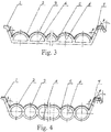
Fig. 3 is a structural schematic view of a cross section of a tile plate with a semicircle shaped heat conduction chamber provided on a roof. -
Fig. 4 is a structural schematic view of a cross section of a tile plate with a circular shaped heat conduction chamber provided on a roof. -
Fig. 5 is a structural schematic view of a cross section of a wall plate with a squircle shaped heat conduction chamber provided on a wall. -
Fig. 6 is a structural schematic view of a cross section of a wall plate with a rounded rectangle shaped heat conduction chamber provided on the wall. -
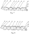
Fig. 7 is a structural schematic view of a cross section of a wall plate with a semicircle shaped heat conduction chamber provided on the wall. -
Fig. 8 is a structural schematic view of a cross section of a wall plate with a circular shaped heat conduction chamber provided on the wall. -
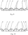
Fig. 9 is a structural schematic view of a cross section of a semicircle shaped heat conduction chamber provided on the wall or the roof. -
Fig. 10 is a structural schematic view of a cross section of a triangle shaped heat conduction chamber provided on the wall or the roof. -
Fig. 11 is a schematic installation view showing that horizontal tube connectors of two adjacent tile plates provide on the roof are connected by a card sleeve. -
Fig. 12 is an A direction view ofFig. 9 . -
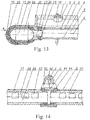
Fig. 13 is a schematic installation view showing that horizontal tube connectors of two adjacent tile plates provide on the roof are connected by a flexible tube. -
Fig. 14 is a B direction view ofFig. 11 . -
Fig. 15 is a schematic installation view showing that horizontal tube connectors of two adjacent wall plates provide on the roof are connected by plug connection.. -
Fig. 16 is a C direction view ofFig. 13 . -
Fig. 17 is a structural schematic view of a thermal insulation tile plate with an insulation layer on a bottom of the tile plate provided on the roof. -
Fig. 18 is a structural schematic view of a thermal insulation wall plate with an insulation layer on a bottom of the wall plate provided on the roof. -
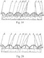
Fig. 19 and Fig. 20 are structural schematic views of a thermal insulation tile plate with an insulation layer on a bottom of the tile plate/wall plate provided on a roof/wall. - Reference numbers in the Figs are as follows.
- 1-left cover; 2- light and heat absorption layer; 3-upper plate; 4-lower plate; 5-connecting rib; 6-heat conduction chamber; 7-right cover; 8-up left concave; 9-left middle convex; 10-left low concave; 11-right up convex; 12-right middle concave; 13-right low convex; 14-left join; 15-right join; 16-fixing lug; 17-card sleeve; 18-concave; 19-sealing ring; 20-inlet; 21-outlet; 22-U-shaped right platform; 23-horizontal tube connector A; 24-tube cavity; 25-baffle plate A; 26-thermal medium; 27-connecting pipe hole A; 28-connecting pipe A; 29-external pallet; 30-screw nail; 31-end cap; 32-U-shaped left sockolet; 33-U-shaped left platform; 34-U-shaped right sockolet; 35-card shell; 36-flexible pipe; 37-horizontal tube connector B; 38-baffle plate B; 39-left plug bush; 40-"o" shaped ring; 41-right plug bush; 42- horizontal tube connector C; 43- connecting pipe hole B; 44-connecting pipe B; 45-bolt; 46-insulating layer; 47-external backplate.
- Referring to
Figs. 1-4 of the drawings, according to a preferred embodiment of the present invention, a multi-functional multi-purpose tile is in a shape of a long strip. A plurality ofheat conduction chambers 6 are separated by a plurality of connectingribs 5 and evenly provided between anupper plate 3 and alower plate 4, so as to form a long strip plate with multi-holes. Aleft cover plate 1 and aright cover plate 8 are respectively provided on two side edges of the tile and both have an included angle of β. A top portion of the left cover plate A is horizontally bended by a certain length, and a top portion of theright cover plate 7 is horizontally bended by a certain length and then a horizontal bend of the right cover plate is bended downwardly with a included angle of β. β varies within a range of 10-80 degrees. The three angles in one tile are equal. A light andheat absorption layer 2, a photovoltaic layer or a thermal transmitting layer is provided on theupper plate 3, theleft cover plate 1 and theright cover plate 7 of the tile. - Referring to
Figs. 5-8 of the drawings, according to a preferred embodiment of the present invention, a multi-functional multi-purpose wall plate is in a shape of a long strip. A plurality ofheat conduction chambers 6 are separated by a plurality of connectingribs 5 and evenly provided between anupper plate 3 and alower plate 4, so as to form a long strip wall plate with multi-holes. Three layers of up, middle or low concave or convex are provided on two side walls of the wall plate. An up left concave 8 is provided on an up layer of a left edge; aleft middle convex 9 is provided on a middle layer of the left edge and a left low concave 10 is provided on a low layer of the left edge. A right up convex 11 is provided on an up layer of a right edge of the wall plate, a right middle concave 12 is provided on a middle layer of the right edge and a rightlow convex 13 is provided on a low layer of the right edge. The concave or convex on the up layer, the middle layer and the low layer are in opposite direction. Length of the concave and the convex on the left side or the right side in an identical layer are equal. A light andheat absorption layer 2 is provided on an up plane of theupper plate 3 of the wall plane, and the effect and a shape of theheat conduction chamber 6 of the light andheat absorption layer 2 is identical to the tile. - Referring to
Fig. 9 , according to a preferred embodiment of the present invention, a multi-functional multipurpose tile plat is in a shape of a long strip. Theupper plate 3 is in a semicircular shape, a light andheat absorption layer 2 is provided on a top external surface of theupper plate 3, thelower plate 4 is a straight plate, a plurality of connectingribs 5 are provided between theupper plate 3 and thelower plate 4, wherein theupper plate 3, thelower plate 4 and the connectingribs 5 form theheat conduction chamber 6; aleft join 14 is provided on a left end of the tile plate or the wall plate, and a hook which has an upward convex is provided on a left external end of the tile plate or the wall plate; aright join 15 is provided on a right end of the tile plate or the wall plate, and a hook which has a downward convex is provided on a right external end of the tile plate or the wall plate; two adjacent tile plate or wall plate are connected by insert an up left convex and a down left convex; afixing lug 16 is provide on a right end surface of the tile plate or the wall plate, wherein thefixing lug 16 is fixed on a rooftop or a wall surface by a screw fastener. - Referring to
Figs. 10 of the drawings, a multi-functional multipurpose wall plate is in a shape of a long strip. Theupper plate 3 can be in a shape of triangles. A light andheat absorption layer 2 is provided on an external side of the wall plate and thelower plate 4 is straight. Other structures and installation are identical toFig. 9 . The light andheat absorption layer 2 inFig.9 and Fig. 10 can be a photovoltaic layer or a thermal transmission layer. - The
heat conduction chamber 6 is formed by theupper plate 3, thelower plate 4 and connectingribs 5;
wherein theupper plate 3 and thelower plate 4 are in a circular arc shape, the connecting ribs are in a linear shape; or theupper plate 3, thelower plate 4 and the connecting ribs are in a linear shape, and four corners of theupper plate 3 and thelower plate 4 are in a circular arc shape; the upper plate and the connectingribs 5 are in a circular shape and thelower plate 4 is in a linear shape; or theupper plate 3, thelower plate 4 and the connectingribs 5 are all in a circular shape; or theupper plate 3, thelower plate 4 and the connectingribs 5 are all in a linear shape; or theupper plate 3 is in a semicircle shape and thelower plate 4 and the connectingribs 5 are in a linear shape; or theupper plate 3 is in a triangle shape, thelower plate 4 and the connectingribs 5 are in a linear shape. -
Fig. 11 and Fig. 12 are a schematic installation views showing connections between two adjacent tile plates, between the tile and the horizontal tube connector; and between two adjacent horizontal tube connectors; and showing cycling operation of the integral engineering of the tile plate connected by card sleeve which is filled withthermal medium 26. The horizontal tube connector A 23 is an oval pipe, a connecting pipe A 28 iexternally provided on a right side of the horizontal tube connector A 23, a shape of a periphery of the connecting pipe A 28 is identical to an internal hole of the heat conduction chamber (6), so as to match and connected the connecting pipe A 28 with the internal hole of the heat conduction chamber 6; the connecting pipe A 28 has a connecting pipe hole A 27 connected therein for communicating a tube cavity 24; external pallets 29 are respectively provided on an upper side or a lower side of each of the connecting pipes A 28; a space for connecting each of the connecting ribs 5 is provided between two adjacent connecting pipes A 28, so as to form a structure that is capable of inserting the upper plate 3, the lower plate 4 and the connecting ribs 5 of the tile or plate into a concave on a right side of a horizontal tube connector A 23; and the tile or the plate is connected to the horizontal tube connector A 23 to form an integral structure by adhering or welding; a U-shaped left tube 33 which has a larger diameter than the horizontal tube connector A 23 is sleeved around three peripheral directions on a left side of the horizontal tube connector A 23, a U-shaped right tube 22 which has a larger diameter than the horizontal tube connector A 23 is sleeved around three peripheral directions on a right side of the horizontal tube connector A 23, a plurality of oval concaves 18 with sealing rings 19 provided thereon are provided on a periphery of the horizontal tube connector A 23; wherein the sealing rings 19 have two types of structures comprising an oval ring and an oval ring with a film shield. SeeFig. 12 . - The multi-functional multi-purpose tile or plate further comprises a draw-in attachment 17 which is U-shaped, and a U-shaped left sockolet 32 is provided in a left side of the draw-in attachment 17, and a U-shaped right sockolet 34 is provided on a right side of the draw-in attachment 17, the U-shaped left sockolet 32 and the U-shaped right sockolet 34 are inserted onto the U-shaped left tube 33 and the U-shaped right tube 22 on two ends of two adjacent horizontal tube connector A 23, in such a manner that adjacent horizontal tube connectors A 23 are tightly connected, and the adjacent horizontal tube connectors A 23 are sealed by a sealing ring 19 with a film shield on an end surface; a baffle plate A 25 for blocking the left cover plate 1 and the right cover plate 7 of two adjacent tiles or plates are provided upwardly on a right end surface of the draw-in attachment 17; a screw nail passes through the two adjacent tiles or plates, the left cover plate 1 and the right cover plate 7 to fixedly fasten the two adjacent tiles or plates to a roof; an end cap 31 is provided on a left side surface of the horizontal tube connector A 23 on a left side, an inlet 20 is provided on an up surface of the horizontal tube connector A 23 on the left side, and an outlet 21 is provided on the horizontal tube connector A 23 on a right side; wherein the inlet 20 and the outlet 21 is communicated with an insulation barrel outside; the insulation barrel, the horizontal tube connector A 23, the tube cavity 24, the connecting pipe hole 27 and the heat conduction chamber 6 are filled with thermal medium 26, so as to absorb heat of sunlight by light and heat absorption layer 2 to form a heat circulation engineering; if the heat absorption layer 2 of the upper plate 3 of the tile or the plate adopts a photovoltaic layer, a double system engineering of heat and power supplying is achieved.
- In
Fig. 13 and 14 , two adjacent horizontaltube connectors B 37 are connected by aflexible pipe 36, a left end portion and a right end portion of the horizontaltube connector B 37 are oval in shape and with inverted teeth, and the left end and the right end of the has smaller diameter than other portion of the horizontaltube connector B 37; theflexible pipe 36 is in shape of a oval ring, end portions of theflexible pipe 36 is thickened in surfaces of two ends, so as to form a U shape outward, acard shell 35 is provided on a periphery on three directions of theflexible pipe 36, and abaffle plate B 38 is provided upwardly on a right end of thecard shell 35. Other structures and principles are identical toFigs. 11 and 12 . -
Figs. 15 and 16 are a schematic installation views showing an integral wall plate engineering of a plug bush connections between two adjacent wall plates, between the wall plate and the horizontal tube connector C42; and between two adjacent horizontal tube connectors C42; and showing cycling operation principle and structure of filing each pipe and chamber withthermal medium 26. - The multi-functional multi-purpose tile or plate, further comprising a horizontal
tube connector C 42, wherein an external periphery of the horizontaltube connector C 42 is a rectangular tube, and aninner cavity 24, aleft plug bush 39 and aright plug bush 41 are all oval tube, a right side of the horizontaltube connector C 42 extends and a bottom bench of the horizontaltube connector C 42 is connected with a connecting pipe B 44 a shape of a periphery of the right side of the horizontaltube connector C 42 is identical to an inner hole of theheat conduction chamber 6 for connecting a wall plate; a connectingpipe hole B 43 communicated with thetube cavity 24 is provided in the horizontaltube connector C 42, a space for installing the connectingribs 5 is provided between two adjacent connectingpipes B 44, so as to form a structure capable of inserting the connectingpipe B 44 into theheat conduction chamber 6 in the wall plate, and the two adjacent connectingpipes B 44 form an integral structure by adhering or welding. - A
left plug bush 39 having a thickness of a half of a thickness of a tube wall of the horizontaltube connector C 42 is provided on a periphery of an internal hole on a left end of the horizontaltube connector C 42, and aright plug bush 39 having a thickness of a half of a thickness of a tube wall of the horizontaltube connector C 42 is provided on a periphery on a right end of the horizontaltube connector C 42, a concave of the "o" shapedring 40 is provided on a periphery of the horizontaltube connector C 42 is connected by inserting theleft plug bush 39 and theright plug bush 41 and are sealed with each other by the "o" shapedring 40. - The light and
heat absorption layer 2 is provided on an up surface of the horizontaltube connector C 42 and theupper plate 3 of the wall plate; two adjacent wall plates are connected with each other by convexes and a concaves on a left end surface and a right end surface thereof, and abolt 45 passes through the right low convex 13 to fix the wall plate. - A first end of the horizontal
tube connector C 42 on a lower portion of the wall plate is connected with a bottom of the insulation barrels by pipes, and a second end thereof is sealed; a first end of the horizontaltube connector C 42 on an upper portion of the wall plate is connected with an up portion of the insulation barrels by pipes, and a second end thereof is sealed; the insulation barrel, thetube cavity 24 of the horizontaltube connector C 42, and theheat conduction chamber 6 are filled withthermal medium 26, so as to absorb heat of sunlight by light andheat absorption layer 2 to form a heat circulation engineering; if theheat absorption layer 2 adopts a photovoltaic layer, a double system engineering of heat and power supplying is achieved. - Referring
Figs. 17-20 , an insulatinglayer 46 is provided on a bottom of the tile plate and the wall plate, and the insulatinglayer 46 is connected with the tile plate or the wall plate via anexternal backplate 47 to form an integral structure, in such a manner that a thermal insulation tile plate and a thermal insulation wall plate are formed for an energy-saving emission reduction engineering.
Claims (6)
- A multi-functional multi-purpose tile or plate, comprising: a plurality of heat conduction chambers (6) which are in a shape of a semicircle, a circle, a squircle, a rounded rectangle or a rhombus is evenly provided between an upper plate (3) and a lower plate (4) by a plurality of connecting ribs (5), so as to form a perforated plate; a left cover plate (1) and a right cover plate (7), concave and convex, or hook shaped embedded device are respectively provided upwardly on a left end edge or a right end edge of the multi-functional multi-purpose plate; two ends of the multi-functional multi-purpose plate are communicated with each of the heat conduction chamber (6) via horizontal tube connectors (23); horizontal tube connectors (23) of two adjacent plates are connected by a card sleeve (17), a flexible tube (36) or a plug bush (39), so as to form an integrated circulatory system,
wherein a multi-functional multi-purpose tile is in a shape of a long strip, a plurality of heat conduction chambers (6) are separated by a plurality of connecting ribs (5) and evenly provided between an upper plate (3) and a lower plate (4), so as to form a long strip plate with multi-holes; a left cover plate (1) and a right cover plate (7) are respectively provided on two side edges of the tile and both have an included angle of β, a top portion of the left cover plate A is horizontally bended by a certain length, and a top portion of the right cover plate (7) is horizontally bended by a certain length and then a horizontal bend of the right cover plate (7) is bended downwardly with a included angle of β, wherein β varies within a range of 10-80 degrees, three angles in one tile are equal; a light and heat absorption layer (2), a photovoltaic layer or a thermal transmitting layer is provided on the upper plate (3), the left cover plate (1) and the right cover plate (7) of the tile; and
wherein a horizontal tube connector A (23) is an oval pipe, a connecting pipe A (28) is externally provided on a right side of the horizontal tube connector A (23), a shape of a periphery of the connecting pipe A (28) is identical to an internal hole of the heat conduction chamber (6), so as to match and connect the connecting pipe A (28) with the internal hole of the heat conduction chamber (6); the connecting pipe A (28) has a connecting pipe hole A (27) connected therein for communicating a tube cavity (24); external pallets (29) are respectively provided on an upper side or a lower side of each of the connecting pipes A (28); a space for connecting each of the connecting ribs (5) is provided between two adjacent connecting pipes A (28), so as to form a structure that is capable of inserting the upper plate (3), the lower plate (4) and the connecting ribs (5) of the tile or plate into a concave on a right side of a horizontal tube connector A (23); and the tile or the plate is connected to the horizontal tube connector A (23) to form an integral structure by adhering or welding; a U-shaped left tube (33) which has a larger diameter than the horizontal tube connector A (23) is sleeved around three peripheral directions on a left side of the horizontal tube connector A (23), a U-shaped right tube (22) which has a larger diameter than the horizontal tube connector A (23) is sleeved around three peripheral directions on a right side of the horizontal tube connector A (23), a plurality of oval concaves (18) with sealing rings (19) provided thereon are provided on a periphery of the horizontal tube connector A (23); wherein the sealing rings (19) have two types of structures comprising an oval ring and an oval ring with a film shield. - The multi-functional multi-purpose tile or plate, as recited in claim 1, further comprising a draw-in attachment (17) which is U-shaped, and a U-shaped left sockolet (32) is provided in a left side of the draw-in attachment (17), and a U-shaped right sockolet (34) is provided on a right side of the draw-in attachment (17), the U-shaped left sockolet (32) and the U-shaped right sockolet (34) are inserted onto the U-shaped left tube (33) and the U-shaped right tube (22) on two ends of two adjacent horizontal tube connector A (23), in such a manner that adjacent horizontal tube connectors A (23) are tightly connected, and the adjacent horizontal tube connectors A (23) are sealed by a sealing ring (19) with a film shield on an end surface; a baffle plate A (25) for blocking the left cover plate (1) and the right cover plate (7) of two adjacent tiles or plates are provided upwardly on a right end surface of the draw-in attachment (17); a screw nail passes through the two adjacent tiles or plates, the left cover plate (1) and the right cover plate (7) to fixedly fasten the two adjacent tiles or plates to a roof; an end cap (31) is provided on a left side surface of the horizontal tube connector A (23) on a left side, an inlet (20) is provided on an up surface of the horizontal tube connector A (23) on the left side, and an outlet (21) is provided on the horizontal tube connector A (23) on a right side; wherein the inlet (20) and the outlet (21) is communicated with an insulation barrel outside; the insulation barrel, the horizontal tube connector A (23), the tube cavity (24), the connecting pipe hole (27) and the heat conduction chamber (6) are filled with thermal medium (26), so as to absorb heat of sunlight by light and heat absorption layer (2) to form a heat circulation engineering; if the heat absorption layer (2) of the upper plate (3) of the tile or the plate adopts a photovoltaic layer, a double system engineering of heat and power supplying is achieved.
- The multi-functional multi-purpose tile or plate, as recited in claim 1, further comprising a plurality of horizontal tube connectors B (37), wherein two adjacent horizontal tube connectors B (37) are connected by a flexible pipe (36), a left end portion and a right end portion of the horizontal tube connector B (37) are oval in shape and with inverted teeth, and the left end and the right end of the has smaller diameter than other portion of the horizontal tube connector B (37); the flexible pipe (36) is in shape of a oval ring, end portions of the flexible pipe (36) is thickened in surfaces of two ends, so as to form a U shape outward, a card shell (35) is provided on a periphery on three directions of the flexible pipe (36), and a baffle plate B (38) is provided upwardly on a right end of the card shell (35).
- The multi-functional multi-purpose tile or plate, as recited in claim 1, further comprising a horizontal tube connector C (42), wherein an external periphery of the horizontal tube connector C (42) is a rectangular tube, and an inner cavity (24), a left plug bush (39) and a right plug bush (41) are all oval tube, a right side of the horizontal tube connector C (42) extends and a bottom bench of the horizontal tube connector C (42) is connected with a connecting pipe B (44), a shape of a periphery of the right side of the horizontal tube connector C (42) is identical to an inner hole of the heat conduction chamber (6) for connecting a wall plate; a connecting pipe hole B (43) communicated with the tube cavity (24) is provided in the horizontal tube connector C (42), a space for installing the connecting ribs (5) is provided between two adjacent connecting pipes B (44), so as to form a structure capable of inserting the connecting pipe B (44) into the heat conduction chamber (6) in the wall plate, and the two adjacent connecting pipes B (44) form an integral structure by adhering or welding.
- The multi-functional multi-purpose tile or plate, as recited in claim 1 or 4, wherein a left plug bush (39) having a thickness of a half of a thickness of a tube wall of the horizontal tube connector C (42) is provided on a periphery of an internal hole on a left end of the horizontal tube connector C (42), and a right plug bush (39) having a thickness of a half of a thickness of a tube wall of the horizontal tube connector C (42) is provided on a periphery on a right end of the horizontal tube connector C (42), a concave of the "o" shaped ring (40) is provided on a periphery of the horizontal tube connector C (42) is connected by inserting the left plug bush (39) and the right plug bush (41) and are sealed with each other by the "o" shaped ring (40); the light and heat absorption layer (2) is provided on an up surface of the horizontal tube connector C (42) and the upper plate (3) of the wall plate; two adjacent wall plates are connected with each other by convexes and a concaves on a left end surface and a right end surface thereof, and a bolt (45) passes through the right low convex (13) to fix the wall plate; a first end of the horizontal tube connector C (42) on a lower portion of the wall plate is connected with a bottom of the insulation barrels by pipes, and a second end thereof is sealed; a first end of the horizontal tube connector C (42) on an upper portion of the wall plate is connected with an up portion of the insulation barrels by pipes, and a second end thereof is sealed; the insulation barrel, the tube cavity (24) of the horizontal tube connector C (42), and the heat conduction chamber (6) are filled with thermal medium (26), so as to absorb heat of sunlight by light and heat absorption layer (2) to form a heat circulation engineering; if the heat absorption layer (2) adopts a photovoltaic layer, a double system engineering of heat and power supplying is achieved.
- The multi-functional multi-purpose tile or plate, as recited in claim 1, wherein an insulating layer (46) is provided on a bottom of the tile plate and the wall plate, and the insulating layer (46) is connected with the tile plate or the wall plate via an external backplate (47) to form an integral structure, in such a manner that a thermal insulation tile plate and a thermal insulation wall plate are formed for an energy-saving emission reduction engineering.
Priority Applications (1)
| Application Number | Priority Date | Filing Date | Title |
|---|---|---|---|
| PL14894197T PL3156557T3 (en) | 2014-06-13 | 2014-07-24 | Multi-functional multi-purpose tile and plate |
Applications Claiming Priority (2)
| Application Number | Priority Date | Filing Date | Title |
|---|---|---|---|
| CN201410260677.9A CN104746812B (en) | 2014-06-13 | 2014-06-13 | A kind of multi-functional, multiduty shoe plate and wallboard |
| PCT/CN2014/000703 WO2015188291A1 (en) | 2014-06-13 | 2014-07-24 | Multi-functional multi-purpose tile and plate |
Publications (3)
| Publication Number | Publication Date |
|---|---|
| EP3156557A1 EP3156557A1 (en) | 2017-04-19 |
| EP3156557A4 EP3156557A4 (en) | 2018-02-21 |
| EP3156557B1 true EP3156557B1 (en) | 2019-10-16 |
Family
ID=53587010
Family Applications (1)
| Application Number | Title | Priority Date | Filing Date |
|---|---|---|---|
| EP14894197.4A Active EP3156557B1 (en) | 2014-06-13 | 2014-07-24 | Multi-functional multi-purpose tile and plate |
Country Status (7)
| Country | Link |
|---|---|
| US (1) | US11428439B2 (en) |
| EP (1) | EP3156557B1 (en) |
| CN (1) | CN104746812B (en) |
| DK (1) | DK3156557T3 (en) |
| ES (1) | ES2767107T3 (en) |
| PL (1) | PL3156557T3 (en) |
| WO (1) | WO2015188291A1 (en) |
Families Citing this family (7)
| Publication number | Priority date | Publication date | Assignee | Title |
|---|---|---|---|---|
| GB2527338B (en) * | 2014-06-19 | 2018-11-07 | ECONOTHERM UK Ltd | Heat transfer apparatus |
| EP3333501B1 (en) * | 2016-12-09 | 2021-02-03 | Grigorij Wagner | Fluid conduit system |
| NL2018970B1 (en) * | 2017-05-23 | 2018-12-04 | Innovations 4 Flooring Holding Nv | Multi-purpose tile system |
| CN111829200A (en) * | 2020-07-13 | 2020-10-27 | 北京瓦得能科技有限公司 | An end connector for solar panels or solar tiles |
| CN112324075A (en) * | 2020-10-19 | 2021-02-05 | 北京瓦得能科技有限公司 | Indoor temperature-regulating decorative board |
| CN113091297B (en) * | 2021-04-13 | 2023-06-23 | 青岛海尔空调器有限总公司 | A kind of air conditioning pipeline structure and air conditioner |
| CN114017953A (en) * | 2021-11-17 | 2022-02-08 | 北京瓦得能科技有限公司 | Solar tile or wallboard evaporator for air conditioning system |
Citations (2)
| Publication number | Priority date | Publication date | Assignee | Title |
|---|---|---|---|---|
| GB1530980A (en) * | 1976-06-11 | 1978-11-01 | Straza G | Solar heating shingle roof structure |
| CN101353923A (en) * | 2008-08-19 | 2009-01-28 | 范东杰 | Aluminum alloy non-welding and roof tile solar heat collector |
Family Cites Families (52)
| Publication number | Priority date | Publication date | Assignee | Title |
|---|---|---|---|---|
| US3981294A (en) * | 1973-11-16 | 1976-09-21 | The Boeing Company | All glass composite building panels |
| US4098331A (en) * | 1974-10-07 | 1978-07-04 | Fafco, Incorporated | Solar heat exchange panel and method of fabrication |
| FR2308064A1 (en) * | 1975-04-16 | 1976-11-12 | Chambrun Jean Francois De | Solar heat exchanger - has flow passages in panel extending into slotted tubular manifolds with end caps |
| US4178914A (en) * | 1975-12-31 | 1979-12-18 | The Franklin Institute | Header for a solar energy collection system |
| US4114597A (en) * | 1975-12-31 | 1978-09-19 | The Franklin Institute | Unitary solar collector |
| US4076013A (en) * | 1976-03-11 | 1978-02-28 | Universal Construction Industries, Inc. | Solar heating system |
| US4150720A (en) * | 1976-04-29 | 1979-04-24 | Imperial Chemical Industries Limited | Heat exchanger |
| US4120286A (en) * | 1976-06-07 | 1978-10-17 | Joseph Farber | Ridged surface solar heater |
| DE2632373A1 (en) * | 1976-07-19 | 1978-01-26 | Erbsloeh Julius & August | Solar heating system heat collector - has intermediate and end supports carrying windows, collector plates, bases and seals |
| FR2360049A1 (en) * | 1976-07-27 | 1978-02-24 | Renault | SOLAR ENERGY COLLECTOR |
| NZ181854A (en) * | 1976-08-25 | 1980-03-05 | W J Wilson | Solar heating panel internal divisions to reduce connection losses |
| IT1064032B (en) * | 1976-11-15 | 1985-02-18 | Pirelli | PANEL FOR THE EXPLOITATION OF SOLAR ENERGY |
| DE2711058A1 (en) * | 1977-03-14 | 1978-09-28 | Maschf Augsburg Nuernberg Ag | Solar energy collector - formed from extruded plastic sheet with passages for heat transfer medium |
| CA1092462A (en) * | 1977-06-20 | 1980-12-30 | Peter J. Hastwell | Solar heater roof-panel construction |
| US4222373A (en) * | 1977-07-26 | 1980-09-16 | Davis Michael A | Ceramic solar collector |
| US4221210A (en) * | 1977-08-01 | 1980-09-09 | Heliotherme, Inc. | System and method for collecting energy from the sun |
| US4300539A (en) * | 1978-09-22 | 1981-11-17 | Ecosol Materials, Inc. | Solar collector |
| NO790160L (en) * | 1979-01-17 | 1980-07-18 | Moelven Brug As | SOLAR PRISONERS. |
| US4257398A (en) * | 1979-03-26 | 1981-03-24 | Watson W Keith R | High efficiency solar collector |
| US4281642A (en) * | 1979-11-05 | 1981-08-04 | Steinberg Hyman A | Solar collector construction |
| US4426997A (en) * | 1980-10-03 | 1984-01-24 | Bette Joseph A | Solar energy panel |
| JPS5784951A (en) | 1980-11-15 | 1982-05-27 | Matsushita Electric Works Ltd | Structure of solar heat collecting roof |
| DE3210607A1 (en) * | 1982-03-23 | 1983-09-29 | Heinz Ing.(grad.) 8644 Pressig Carl | Roof made of prefabricated concrete slabs |
| US4455999A (en) * | 1981-07-20 | 1984-06-26 | Ingenuin Heckenbleikner | Solar hot-water heaters |
| DE3310738A1 (en) * | 1983-03-24 | 1984-09-27 | Weber, geb. Fischer, Helga, 5206 Neunkirchen-Seelscheid | Heat exchanger |
| JPS6036842A (en) * | 1983-08-08 | 1985-02-26 | Showa Denko Kk | Heat collector for hot water boiler |
| US4520796A (en) * | 1984-03-26 | 1985-06-04 | J. Michael Slaminski | Lightweight solar collector |
| US4867133A (en) * | 1986-03-26 | 1989-09-19 | Charlton Sadler | Solar collector method and apparatus |
| CN86210434U (en) * | 1986-12-16 | 1987-10-28 | 山东省新材料研究所 | Black ceramics solar energy heat collecting tile with bell and spigot joint |
| US5217000A (en) * | 1988-02-23 | 1993-06-08 | Pierce Bjorklund Patricia | Compound solar collector building construction |
| DE3913552A1 (en) * | 1989-04-25 | 1990-10-31 | Ulrich Dipl Ing Brandt | Conservatory roof made from transparent plastics panels - which have internal passageways for circulating heat absorbing liquid |
| US5645045A (en) * | 1995-06-02 | 1997-07-08 | Bres Llc | Fluid heating apparatus using light energy and method thereof |
| DE19607033A1 (en) * | 1996-02-24 | 1997-08-28 | Bernd Dipl Ing Bartelsen | Solar collector, especially for water heating in homes or factories |
| US6880553B2 (en) * | 2003-05-27 | 2005-04-19 | Atomic Energy Council-Institute Of Nuclear Energy | Solar air conditioning system |
| CN200993485Y (en) | 2006-12-22 | 2007-12-19 | 檀廷锋 | Tile type solar water heater |
| US20080236572A1 (en) * | 2007-03-26 | 2008-10-02 | Guenter Schaefer | Solar heating panel fabricated from multi-wall plastic sheets |
| CN101319820B (en) * | 2007-06-08 | 2010-12-22 | 富准精密工业(深圳)有限公司 | Natural air conditioner |
| US7757687B2 (en) * | 2007-12-27 | 2010-07-20 | Fu Zhun Precision Industry (Shenzhen) Co., Ltd. | Solar air conditioning apparatus |
| CN101709597B (en) | 2009-07-10 | 2011-04-27 | 王子韩 | Concentrating solar tile capable of supplying heat and generating power |
| US9103564B2 (en) * | 2009-10-16 | 2015-08-11 | Soleeva Corporation | Solar energy converter and method for converting solar energy |
| NO333520B1 (en) * | 2009-11-06 | 2013-07-01 | Flaax Holding As | solar tariff |
| CN102141309A (en) * | 2010-01-28 | 2011-08-03 | 丁琪 | Novel safe cleanable solar thermal collector with thermal-insulation roller shutter |
| DE102011054649B4 (en) * | 2011-10-20 | 2016-12-01 | Circle GmbH | Covering element for roofs or other surfaces exposed to solar energy and system for the use of solar energy |
| US20130333310A1 (en) * | 2012-06-15 | 2013-12-19 | Mas S.R.L. | Modular Structure, Modular Panel To Make Said Modular Structure And Corresponding Method To Make Said Modular Structure |
| FI126124B (en) * | 2012-10-04 | 2016-06-30 | Double M Properties Ab | Solar collector, building roof, building and solar energy recovery system |
| CN203022246U (en) | 2012-12-05 | 2013-06-26 | 瞿云亮 | Solar thermal insulation tile panel and collecting panel |
| CN103850405A (en) * | 2012-12-05 | 2014-06-11 | 瞿云亮 | Solar heat-preserving tile plate and collecting plate |
| EP2972002A4 (en) * | 2013-03-13 | 2016-11-16 | Helios Products Llc | Translucent plastic solar thermal collector |
| CN203595304U (en) * | 2013-06-06 | 2014-05-14 | 瞿云亮 | Communicating pipe for end of solar insulating roofing slate or collecting plate |
| CL2013002719A1 (en) * | 2013-09-24 | 2014-05-30 | Univ Pontificia Catolica Chile | A device for the rigidity and sealing of the connection area between a solar absorber and fluid collectors of a solar collector, comprising a support profile formed by open cylindrical modules and a plastic tray that holds the absorber and the collectors as a common element |
| CN204001485U (en) * | 2014-06-13 | 2014-12-10 | 北京瓦得能科技有限公司 | A kind of multipurpose watt plate |
| DE102016107016B4 (en) * | 2016-04-15 | 2017-11-02 | Paxos Consulting & Engineering GmbH & Co. KG | Solar energy roof tile with variable length connecting element |
-
2014
- 2014-06-13 CN CN201410260677.9A patent/CN104746812B/en active Active
- 2014-07-24 EP EP14894197.4A patent/EP3156557B1/en active Active
- 2014-07-24 DK DK14894197.4T patent/DK3156557T3/en active
- 2014-07-24 PL PL14894197T patent/PL3156557T3/en unknown
- 2014-07-24 US US15/316,836 patent/US11428439B2/en active Active
- 2014-07-24 WO PCT/CN2014/000703 patent/WO2015188291A1/en not_active Ceased
- 2014-07-24 ES ES14894197T patent/ES2767107T3/en active Active
Patent Citations (2)
| Publication number | Priority date | Publication date | Assignee | Title |
|---|---|---|---|---|
| GB1530980A (en) * | 1976-06-11 | 1978-11-01 | Straza G | Solar heating shingle roof structure |
| CN101353923A (en) * | 2008-08-19 | 2009-01-28 | 范东杰 | Aluminum alloy non-welding and roof tile solar heat collector |
Also Published As
| Publication number | Publication date |
|---|---|
| EP3156557A1 (en) | 2017-04-19 |
| US20170108243A1 (en) | 2017-04-20 |
| US11428439B2 (en) | 2022-08-30 |
| DK3156557T3 (en) | 2020-01-27 |
| ES2767107T3 (en) | 2020-06-16 |
| PL3156557T3 (en) | 2020-05-18 |
| CN104746812B (en) | 2017-11-28 |
| EP3156557A4 (en) | 2018-02-21 |
| CN104746812A (en) | 2015-07-01 |
| WO2015188291A1 (en) | 2015-12-17 |
Similar Documents
| Publication | Publication Date | Title |
|---|---|---|
| US11428439B2 (en) | Multi-functional multi-purpose tile and plate | |
| CN203385218U (en) | Flat plate solar collector | |
| EP4086558A1 (en) | Heat pipe and geothermal energy collection device | |
| CN106123610A (en) | A kind of S-shaped unit pipes heating energy saving environment protection exchange method | |
| CN204678708U (en) | Stainless steel corrugated type solar heat collector | |
| CN204001485U (en) | A kind of multipurpose watt plate | |
| CN203385219U (en) | Solar heat collector | |
| CN205717989U (en) | Multifunctional solar energy heat collecting device | |
| CN202470486U (en) | Tile type solar heat collection device | |
| CN102538226A (en) | Large-caliber glass and metal covering solarization type solar water heater | |
| CN202885284U (en) | Vacuum flat heat collector | |
| CN212226346U (en) | Socket type flexible interface of flat plate type solar heat collector | |
| CN216694045U (en) | Novel solar energy engineering header heat collector | |
| CN205606929U (en) | Superconducting heat pipe structure and solar collector | |
| CN110350824A (en) | A kind of tepor difference power generation mechanism with backheating function | |
| CN202757321U (en) | Glass evacuated collector tube for building tiles | |
| CN208075352U (en) | Plate core module, absorber plate and solar water heater | |
| CN204100616U (en) | Heat accumulation type flat-panel solar thermal collector | |
| CN201615621U (en) | Wall-mounted full-automatic solar water heater | |
| CN203771731U (en) | Flat-plate solar water heater | |
| CN203148087U (en) | Efficient flat-plate solar thermal collector with vacuum separating cover | |
| CN202370122U (en) | Anti-drop installing construction member based on light-weight insulating brick | |
| CN102840689A (en) | Solar heat collector | |
| CN203336867U (en) | Connection clamp of solar heat preserving roofing slate communicating pipes or collecting plate communicating pipes | |
| CN1364993A (en) | Aluminium alloy flat plate type solar energy collector |
Legal Events
| Date | Code | Title | Description |
|---|---|---|---|
| STAA | Information on the status of an ep patent application or granted ep patent |
Free format text: STATUS: THE INTERNATIONAL PUBLICATION HAS BEEN MADE |
|
| PUAI | Public reference made under article 153(3) epc to a published international application that has entered the european phase |
Free format text: ORIGINAL CODE: 0009012 |
|
| STAA | Information on the status of an ep patent application or granted ep patent |
Free format text: STATUS: REQUEST FOR EXAMINATION WAS MADE |
|
| 17P | Request for examination filed |
Effective date: 20170112 |
|
| AK | Designated contracting states |
Kind code of ref document: A1 Designated state(s): AL AT BE BG CH CY CZ DE DK EE ES FI FR GB GR HR HU IE IS IT LI LT LU LV MC MK MT NL NO PL PT RO RS SE SI SK SM TR |
|
| AX | Request for extension of the european patent |
Extension state: BA ME |
|
| DAX | Request for extension of the european patent (deleted) | ||
| A4 | Supplementary search report drawn up and despatched |
Effective date: 20180124 |
|
| RIC1 | Information provided on ipc code assigned before grant |
Ipc: E04D 13/18 20180101AFI20180118BHEP Ipc: F28F 13/18 20060101ALI20180118BHEP Ipc: F24S 10/00 20180101ALI20180118BHEP Ipc: F28F 3/12 20060101ALI20180118BHEP |
|
| STAA | Information on the status of an ep patent application or granted ep patent |
Free format text: STATUS: EXAMINATION IS IN PROGRESS |
|
| 17Q | First examination report despatched |
Effective date: 20181114 |
|
| RIC1 | Information provided on ipc code assigned before grant |
Ipc: F28F 3/12 20060101ALI20180118BHEP Ipc: F28F 13/18 20060101ALI20180118BHEP Ipc: E04D 13/18 20180101AFI20180118BHEP Ipc: F24S 10/00 20180101ALI20180118BHEP |
|
| REG | Reference to a national code |
Ref country code: DE Ref legal event code: R079 Ref document number: 602014055431 Country of ref document: DE Free format text: PREVIOUS MAIN CLASS: E04D0013180000 Ipc: F24S0020690000 |
|
| GRAP | Despatch of communication of intention to grant a patent |
Free format text: ORIGINAL CODE: EPIDOSNIGR1 |
|
| STAA | Information on the status of an ep patent application or granted ep patent |
Free format text: STATUS: GRANT OF PATENT IS INTENDED |
|
| RIC1 | Information provided on ipc code assigned before grant |
Ipc: F24S 20/00 20180101ALI20190404BHEP Ipc: F24S 20/61 20180101ALI20190404BHEP Ipc: F28F 13/18 20060101ALI20190404BHEP Ipc: F24S 20/69 20180101AFI20190404BHEP Ipc: F28F 3/12 20060101ALI20190404BHEP |
|
| INTG | Intention to grant announced |
Effective date: 20190429 |
|
| GRAS | Grant fee paid |
Free format text: ORIGINAL CODE: EPIDOSNIGR3 |
|
| GRAA | (expected) grant |
Free format text: ORIGINAL CODE: 0009210 |
|
| STAA | Information on the status of an ep patent application or granted ep patent |
Free format text: STATUS: THE PATENT HAS BEEN GRANTED |
|
| AK | Designated contracting states |
Kind code of ref document: B1 Designated state(s): AL AT BE BG CH CY CZ DE DK EE ES FI FR GB GR HR HU IE IS IT LI LT LU LV MC MK MT NL NO PL PT RO RS SE SI SK SM TR |
|
| REG | Reference to a national code |
Ref country code: GB Ref legal event code: FG4D |
|
| REG | Reference to a national code |
Ref country code: CH Ref legal event code: EP |
|
| REG | Reference to a national code |
Ref country code: DE Ref legal event code: R096 Ref document number: 602014055431 Country of ref document: DE |
|
| REG | Reference to a national code |
Ref country code: IE Ref legal event code: FG4D |
|
| REG | Reference to a national code |
Ref country code: AT Ref legal event code: REF Ref document number: 1191667 Country of ref document: AT Kind code of ref document: T Effective date: 20191115 |
|
| REG | Reference to a national code |
Ref country code: RO Ref legal event code: EPE |
|
| REG | Reference to a national code |
Ref country code: FI Ref legal event code: FGE |
|
| REG | Reference to a national code |
Ref country code: DK Ref legal event code: T3 Effective date: 20200123 |
|
| REG | Reference to a national code |
Ref country code: SE Ref legal event code: TRGR |
|
| REG | Reference to a national code |
Ref country code: NL Ref legal event code: FP |
|
| REG | Reference to a national code |
Ref country code: CH Ref legal event code: NV Representative=s name: VALIPAT S.A. C/O BOVARD SA NEUCHATEL, CH |
|
| REG | Reference to a national code |
Ref country code: LT Ref legal event code: MG4D |
|
| PG25 | Lapsed in a contracting state [announced via postgrant information from national office to epo] |
Ref country code: BG Free format text: LAPSE BECAUSE OF FAILURE TO SUBMIT A TRANSLATION OF THE DESCRIPTION OR TO PAY THE FEE WITHIN THE PRESCRIBED TIME-LIMIT Effective date: 20200116 Ref country code: GR Free format text: LAPSE BECAUSE OF FAILURE TO SUBMIT A TRANSLATION OF THE DESCRIPTION OR TO PAY THE FEE WITHIN THE PRESCRIBED TIME-LIMIT Effective date: 20200117 Ref country code: LT Free format text: LAPSE BECAUSE OF FAILURE TO SUBMIT A TRANSLATION OF THE DESCRIPTION OR TO PAY THE FEE WITHIN THE PRESCRIBED TIME-LIMIT Effective date: 20191016 Ref country code: NO Free format text: LAPSE BECAUSE OF FAILURE TO SUBMIT A TRANSLATION OF THE DESCRIPTION OR TO PAY THE FEE WITHIN THE PRESCRIBED TIME-LIMIT Effective date: 20200116 Ref country code: LV Free format text: LAPSE BECAUSE OF FAILURE TO SUBMIT A TRANSLATION OF THE DESCRIPTION OR TO PAY THE FEE WITHIN THE PRESCRIBED TIME-LIMIT Effective date: 20191016 Ref country code: PT Free format text: LAPSE BECAUSE OF FAILURE TO SUBMIT A TRANSLATION OF THE DESCRIPTION OR TO PAY THE FEE WITHIN THE PRESCRIBED TIME-LIMIT Effective date: 20200217 |
|
| PG25 | Lapsed in a contracting state [announced via postgrant information from national office to epo] |
Ref country code: RS Free format text: LAPSE BECAUSE OF FAILURE TO SUBMIT A TRANSLATION OF THE DESCRIPTION OR TO PAY THE FEE WITHIN THE PRESCRIBED TIME-LIMIT Effective date: 20191016 Ref country code: HR Free format text: LAPSE BECAUSE OF FAILURE TO SUBMIT A TRANSLATION OF THE DESCRIPTION OR TO PAY THE FEE WITHIN THE PRESCRIBED TIME-LIMIT Effective date: 20191016 Ref country code: IS Free format text: LAPSE BECAUSE OF FAILURE TO SUBMIT A TRANSLATION OF THE DESCRIPTION OR TO PAY THE FEE WITHIN THE PRESCRIBED TIME-LIMIT Effective date: 20200224 |
|
| REG | Reference to a national code |
Ref country code: ES Ref legal event code: FG2A Ref document number: 2767107 Country of ref document: ES Kind code of ref document: T3 Effective date: 20200616 |
|
| PG25 | Lapsed in a contracting state [announced via postgrant information from national office to epo] |
Ref country code: AL Free format text: LAPSE BECAUSE OF FAILURE TO SUBMIT A TRANSLATION OF THE DESCRIPTION OR TO PAY THE FEE WITHIN THE PRESCRIBED TIME-LIMIT Effective date: 20191016 |
|
| REG | Reference to a national code |
Ref country code: DE Ref legal event code: R097 Ref document number: 602014055431 Country of ref document: DE |
|
| PG2D | Information on lapse in contracting state deleted |
Ref country code: IS |
|
| PG25 | Lapsed in a contracting state [announced via postgrant information from national office to epo] |
Ref country code: IS Free format text: LAPSE BECAUSE OF FAILURE TO SUBMIT A TRANSLATION OF THE DESCRIPTION OR TO PAY THE FEE WITHIN THE PRESCRIBED TIME-LIMIT Effective date: 20200216 Ref country code: CZ Free format text: LAPSE BECAUSE OF FAILURE TO SUBMIT A TRANSLATION OF THE DESCRIPTION OR TO PAY THE FEE WITHIN THE PRESCRIBED TIME-LIMIT Effective date: 20191016 Ref country code: EE Free format text: LAPSE BECAUSE OF FAILURE TO SUBMIT A TRANSLATION OF THE DESCRIPTION OR TO PAY THE FEE WITHIN THE PRESCRIBED TIME-LIMIT Effective date: 20191016 |
|
| PLBE | No opposition filed within time limit |
Free format text: ORIGINAL CODE: 0009261 |
|
| STAA | Information on the status of an ep patent application or granted ep patent |
Free format text: STATUS: NO OPPOSITION FILED WITHIN TIME LIMIT |
|
| PG25 | Lapsed in a contracting state [announced via postgrant information from national office to epo] |
Ref country code: SK Free format text: LAPSE BECAUSE OF FAILURE TO SUBMIT A TRANSLATION OF THE DESCRIPTION OR TO PAY THE FEE WITHIN THE PRESCRIBED TIME-LIMIT Effective date: 20191016 Ref country code: SM Free format text: LAPSE BECAUSE OF FAILURE TO SUBMIT A TRANSLATION OF THE DESCRIPTION OR TO PAY THE FEE WITHIN THE PRESCRIBED TIME-LIMIT Effective date: 20191016 |
|
| 26N | No opposition filed |
Effective date: 20200717 |
|
| PG25 | Lapsed in a contracting state [announced via postgrant information from national office to epo] |
Ref country code: SI Free format text: LAPSE BECAUSE OF FAILURE TO SUBMIT A TRANSLATION OF THE DESCRIPTION OR TO PAY THE FEE WITHIN THE PRESCRIBED TIME-LIMIT Effective date: 20191016 |
|
| PG25 | Lapsed in a contracting state [announced via postgrant information from national office to epo] |
Ref country code: MC Free format text: LAPSE BECAUSE OF FAILURE TO SUBMIT A TRANSLATION OF THE DESCRIPTION OR TO PAY THE FEE WITHIN THE PRESCRIBED TIME-LIMIT Effective date: 20191016 |
|
| REG | Reference to a national code |
Ref country code: BE Ref legal event code: MM Effective date: 20200731 |
|
| PG25 | Lapsed in a contracting state [announced via postgrant information from national office to epo] |
Ref country code: LU Free format text: LAPSE BECAUSE OF NON-PAYMENT OF DUE FEES Effective date: 20200724 |
|
| PG25 | Lapsed in a contracting state [announced via postgrant information from national office to epo] |
Ref country code: BE Free format text: LAPSE BECAUSE OF NON-PAYMENT OF DUE FEES Effective date: 20200731 |
|
| PG25 | Lapsed in a contracting state [announced via postgrant information from national office to epo] |
Ref country code: IE Free format text: LAPSE BECAUSE OF NON-PAYMENT OF DUE FEES Effective date: 20200724 |
|
| REG | Reference to a national code |
Ref country code: AT Ref legal event code: UEP Ref document number: 1191667 Country of ref document: AT Kind code of ref document: T Effective date: 20191016 |
|
| PG25 | Lapsed in a contracting state [announced via postgrant information from national office to epo] |
Ref country code: TR Free format text: LAPSE BECAUSE OF FAILURE TO SUBMIT A TRANSLATION OF THE DESCRIPTION OR TO PAY THE FEE WITHIN THE PRESCRIBED TIME-LIMIT Effective date: 20191016 Ref country code: MT Free format text: LAPSE BECAUSE OF FAILURE TO SUBMIT A TRANSLATION OF THE DESCRIPTION OR TO PAY THE FEE WITHIN THE PRESCRIBED TIME-LIMIT Effective date: 20191016 Ref country code: CY Free format text: LAPSE BECAUSE OF FAILURE TO SUBMIT A TRANSLATION OF THE DESCRIPTION OR TO PAY THE FEE WITHIN THE PRESCRIBED TIME-LIMIT Effective date: 20191016 |
|
| PG25 | Lapsed in a contracting state [announced via postgrant information from national office to epo] |
Ref country code: MK Free format text: LAPSE BECAUSE OF FAILURE TO SUBMIT A TRANSLATION OF THE DESCRIPTION OR TO PAY THE FEE WITHIN THE PRESCRIBED TIME-LIMIT Effective date: 20191016 |
|
| PGFP | Annual fee paid to national office [announced via postgrant information from national office to epo] |
Ref country code: DK Payment date: 20240628 Year of fee payment: 11 |
|
| PGFP | Annual fee paid to national office [announced via postgrant information from national office to epo] |
Ref country code: NL Payment date: 20240628 Year of fee payment: 11 |
|
| PGFP | Annual fee paid to national office [announced via postgrant information from national office to epo] |
Ref country code: FR Payment date: 20240619 Year of fee payment: 11 Ref country code: FI Payment date: 20240621 Year of fee payment: 11 |
|
| PGFP | Annual fee paid to national office [announced via postgrant information from national office to epo] |
Ref country code: PL Payment date: 20240625 Year of fee payment: 11 |
|
| PGFP | Annual fee paid to national office [announced via postgrant information from national office to epo] |
Ref country code: DE Payment date: 20240712 Year of fee payment: 11 |
|
| PGFP | Annual fee paid to national office [announced via postgrant information from national office to epo] |
Ref country code: GB Payment date: 20240729 Year of fee payment: 11 |
|
| PGFP | Annual fee paid to national office [announced via postgrant information from national office to epo] |
Ref country code: ES Payment date: 20240809 Year of fee payment: 11 Ref country code: CH Payment date: 20240805 Year of fee payment: 11 |
|
| PGFP | Annual fee paid to national office [announced via postgrant information from national office to epo] |
Ref country code: AT Payment date: 20240621 Year of fee payment: 11 |
|
| PGFP | Annual fee paid to national office [announced via postgrant information from national office to epo] |
Ref country code: RO Payment date: 20240701 Year of fee payment: 11 Ref country code: SE Payment date: 20240726 Year of fee payment: 11 Ref country code: IT Payment date: 20240708 Year of fee payment: 11 |
|
| REG | Reference to a national code |
Ref country code: DE Ref legal event code: R119 Ref document number: 602014055431 Country of ref document: DE |
|
| REG | Reference to a national code |
Ref country code: DK Ref legal event code: EBP Effective date: 20250731 |
|
| REG | Reference to a national code |
Ref country code: CH Ref legal event code: H13 Free format text: ST27 STATUS EVENT CODE: U-0-0-H10-H13 (AS PROVIDED BY THE NATIONAL OFFICE) Effective date: 20260224 |
|
| REG | Reference to a national code |
Ref country code: NL Ref legal event code: MM Effective date: 20250801 |
|
| REG | Reference to a national code |
Ref country code: AT Ref legal event code: MM01 Ref document number: 1191667 Country of ref document: AT Kind code of ref document: T Effective date: 20250724 |
|
| GBPC | Gb: european patent ceased through non-payment of renewal fee |
Effective date: 20250724 |
|
| PG25 | Lapsed in a contracting state [announced via postgrant information from national office to epo] |
Ref country code: GB Free format text: LAPSE BECAUSE OF NON-PAYMENT OF DUE FEES Effective date: 20250724 |
|
| PG25 | Lapsed in a contracting state [announced via postgrant information from national office to epo] |
Ref country code: DE Free format text: LAPSE BECAUSE OF NON-PAYMENT OF DUE FEES Effective date: 20260203 |
|
| PG25 | Lapsed in a contracting state [announced via postgrant information from national office to epo] |
Ref country code: FI Free format text: LAPSE BECAUSE OF NON-PAYMENT OF DUE FEES Effective date: 20250724 Ref country code: AT Free format text: LAPSE BECAUSE OF NON-PAYMENT OF DUE FEES Effective date: 20250724 |
|
| PG25 | Lapsed in a contracting state [announced via postgrant information from national office to epo] |
Ref country code: RO Free format text: LAPSE BECAUSE OF NON-PAYMENT OF DUE FEES Effective date: 20250724 |
|
| PG25 | Lapsed in a contracting state [announced via postgrant information from national office to epo] |
Ref country code: NL Free format text: LAPSE BECAUSE OF NON-PAYMENT OF DUE FEES Effective date: 20250801 |
|
| PG25 | Lapsed in a contracting state [announced via postgrant information from national office to epo] |
Ref country code: FR Free format text: LAPSE BECAUSE OF NON-PAYMENT OF DUE FEES Effective date: 20250731 |
|
| PG25 | Lapsed in a contracting state [announced via postgrant information from national office to epo] |
Ref country code: CH Free format text: LAPSE BECAUSE OF NON-PAYMENT OF DUE FEES Effective date: 20250731 |
|
| PG25 | Lapsed in a contracting state [announced via postgrant information from national office to epo] |
Ref country code: DK Free format text: LAPSE BECAUSE OF NON-PAYMENT OF DUE FEES Effective date: 20250731 |
|
| PG25 | Lapsed in a contracting state [announced via postgrant information from national office to epo] |
Ref country code: IT Free format text: LAPSE BECAUSE OF NON-PAYMENT OF DUE FEES Effective date: 20250724 |
|
| PG25 | Lapsed in a contracting state [announced via postgrant information from national office to epo] |
Ref country code: SE Free format text: LAPSE BECAUSE OF NON-PAYMENT OF DUE FEES Effective date: 20250725 |