EP3156516A1 - Arc evaporation source - Google Patents
Arc evaporation source Download PDFInfo
- Publication number
- EP3156516A1 EP3156516A1 EP15827912.5A EP15827912A EP3156516A1 EP 3156516 A1 EP3156516 A1 EP 3156516A1 EP 15827912 A EP15827912 A EP 15827912A EP 3156516 A1 EP3156516 A1 EP 3156516A1
- Authority
- EP
- European Patent Office
- Prior art keywords
- target
- end surface
- evaporation source
- axial direction
- magnet
- Prior art date
- Legal status (The legal status is an assumption and is not a legal conclusion. Google has not performed a legal analysis and makes no representation as to the accuracy of the status listed.)
- Granted
Links
Images



Classifications
-
- C—CHEMISTRY; METALLURGY
- C23—COATING METALLIC MATERIAL; COATING MATERIAL WITH METALLIC MATERIAL; CHEMICAL SURFACE TREATMENT; DIFFUSION TREATMENT OF METALLIC MATERIAL; COATING BY VACUUM EVAPORATION, BY SPUTTERING, BY ION IMPLANTATION OR BY CHEMICAL VAPOUR DEPOSITION, IN GENERAL; INHIBITING CORROSION OF METALLIC MATERIAL OR INCRUSTATION IN GENERAL
- C23C—COATING METALLIC MATERIAL; COATING MATERIAL WITH METALLIC MATERIAL; SURFACE TREATMENT OF METALLIC MATERIAL BY DIFFUSION INTO THE SURFACE, BY CHEMICAL CONVERSION OR SUBSTITUTION; COATING BY VACUUM EVAPORATION, BY SPUTTERING, BY ION IMPLANTATION OR BY CHEMICAL VAPOUR DEPOSITION, IN GENERAL
- C23C14/00—Coating by vacuum evaporation, by sputtering or by ion implantation of the coating forming material
- C23C14/22—Coating by vacuum evaporation, by sputtering or by ion implantation of the coating forming material characterised by the process of coating
- C23C14/24—Vacuum evaporation
- C23C14/243—Crucibles for source material
-
- C—CHEMISTRY; METALLURGY
- C23—COATING METALLIC MATERIAL; COATING MATERIAL WITH METALLIC MATERIAL; CHEMICAL SURFACE TREATMENT; DIFFUSION TREATMENT OF METALLIC MATERIAL; COATING BY VACUUM EVAPORATION, BY SPUTTERING, BY ION IMPLANTATION OR BY CHEMICAL VAPOUR DEPOSITION, IN GENERAL; INHIBITING CORROSION OF METALLIC MATERIAL OR INCRUSTATION IN GENERAL
- C23C—COATING METALLIC MATERIAL; COATING MATERIAL WITH METALLIC MATERIAL; SURFACE TREATMENT OF METALLIC MATERIAL BY DIFFUSION INTO THE SURFACE, BY CHEMICAL CONVERSION OR SUBSTITUTION; COATING BY VACUUM EVAPORATION, BY SPUTTERING, BY ION IMPLANTATION OR BY CHEMICAL VAPOUR DEPOSITION, IN GENERAL
- C23C14/00—Coating by vacuum evaporation, by sputtering or by ion implantation of the coating forming material
- C23C14/22—Coating by vacuum evaporation, by sputtering or by ion implantation of the coating forming material characterised by the process of coating
- C23C14/24—Vacuum evaporation
- C23C14/32—Vacuum evaporation by explosion; by evaporation and subsequent ionisation of the vapours, e.g. ion-plating
-
- C—CHEMISTRY; METALLURGY
- C23—COATING METALLIC MATERIAL; COATING MATERIAL WITH METALLIC MATERIAL; CHEMICAL SURFACE TREATMENT; DIFFUSION TREATMENT OF METALLIC MATERIAL; COATING BY VACUUM EVAPORATION, BY SPUTTERING, BY ION IMPLANTATION OR BY CHEMICAL VAPOUR DEPOSITION, IN GENERAL; INHIBITING CORROSION OF METALLIC MATERIAL OR INCRUSTATION IN GENERAL
- C23C—COATING METALLIC MATERIAL; COATING MATERIAL WITH METALLIC MATERIAL; SURFACE TREATMENT OF METALLIC MATERIAL BY DIFFUSION INTO THE SURFACE, BY CHEMICAL CONVERSION OR SUBSTITUTION; COATING BY VACUUM EVAPORATION, BY SPUTTERING, BY ION IMPLANTATION OR BY CHEMICAL VAPOUR DEPOSITION, IN GENERAL
- C23C14/00—Coating by vacuum evaporation, by sputtering or by ion implantation of the coating forming material
- C23C14/22—Coating by vacuum evaporation, by sputtering or by ion implantation of the coating forming material characterised by the process of coating
- C23C14/24—Vacuum evaporation
- C23C14/32—Vacuum evaporation by explosion; by evaporation and subsequent ionisation of the vapours, e.g. ion-plating
- C23C14/325—Electric arc evaporation
-
- H—ELECTRICITY
- H01—ELECTRIC ELEMENTS
- H01J—ELECTRIC DISCHARGE TUBES OR DISCHARGE LAMPS
- H01J37/00—Discharge tubes with provision for introducing objects or material to be exposed to the discharge, e.g. for the purpose of examination or processing thereof
- H01J37/32—Gas-filled discharge tubes
- H01J37/32009—Arrangements for generation of plasma specially adapted for examination or treatment of objects, e.g. plasma sources
- H01J37/32055—Arc discharge
-
- H—ELECTRICITY
- H01—ELECTRIC ELEMENTS
- H01J—ELECTRIC DISCHARGE TUBES OR DISCHARGE LAMPS
- H01J37/00—Discharge tubes with provision for introducing objects or material to be exposed to the discharge, e.g. for the purpose of examination or processing thereof
- H01J37/32—Gas-filled discharge tubes
- H01J37/32431—Constructional details of the reactor
- H01J37/3266—Magnetic control means
-
- H—ELECTRICITY
- H01—ELECTRIC ELEMENTS
- H01J—ELECTRIC DISCHARGE TUBES OR DISCHARGE LAMPS
- H01J37/00—Discharge tubes with provision for introducing objects or material to be exposed to the discharge, e.g. for the purpose of examination or processing thereof
- H01J37/32—Gas-filled discharge tubes
- H01J37/32431—Constructional details of the reactor
- H01J37/3266—Magnetic control means
- H01J37/32669—Particular magnets or magnet arrangements for controlling the discharge
Definitions
- the present invention relates to an arc evaporation source.
- a method of forming a film on the surface of a substrate such as a tool or a machine part for the purpose of enhancing abrasion resistance or the like
- a method of depositing a film on the surface of the substrate by use of arc discharge As a material of such a film, there may be used, for example, a rod-shaped target in order to allow a continuous film deposition to be performed.
- Patent Literature 1 discloses an arc evaporation source having a rod-shaped target.
- an arc discharge such as AIP
- the front end surface of the rod-shaped target in the arc evaporation source is melted and evaporated by the arc discharge.
- melted and evaporated material adheres on the surface of the substrate.
- the spot at which the arc discharge is caused in the front end surface of the target namely, a target spot
- the spot at which the arc discharge is caused in the front end surface of the target makes an unstable movement.
- This causes the possibility that the arc spot deviates from the area of the front end surface of the target and makes an unexpected or stray movement toward the side surface of the target or away from the target.
- the deposition system has to automatically stop the arc discharge, which may hinder a continuous deposition.
- the arc evaporation source disclosed in Patent Literature 1 includes an annular coil for magnetic field generation, the coil being disposed around the target coaxially with the target.
- the magnetic field generated by the coil there are formed magnetic lines of force extending from the front end surface of the target substantially in a normal direction thereof. The magnetic lines of force thus extending from the front end surface of the target in the normal direction constrains the arc spot within the area of the front end surface of the target.
- Patent Literature 1 the disposition of a magnetic field generation coil around a rod-shaped target such as the arc evaporation source disclosed in Patent Literature 1 requires the coil and/or equipment around the coil to be upsized for generating strong magnetic lined of force, thus generating a problem of increase in a product cost of the arc evaporation source.
- the inventors have conducted extensive research, resulting in finding that the magnetic field formed by a magnet only has to simultaneously satisfy a first condition that the angle of magnetic lines of force with respect to the side surface of the target is lower than a specific magnitude and a second condition that the magnitude of a component of magnetic lines of force in an axial direction of the target is equal to or greater than a specific magnitude, in order to constrain the arc spot within the area of the front end surface of the target.
- disposing the magnet so as to allow the magnet to generate magnetic field satisfying the above conditions makes it possible to restrict equipment upsizing.
- the arc evaporation source according to the invention includes:
- Figs. 1 to 3 show an arc evaporation source 1, which includes: a main body 2; a rod-shaped target 3 made of carbon; a plurality of magnets 4 disposed around the target 3 in a radial arrangement; a shield plate 5 that protects the magnets 4 against arc discharge; a feeding unit 6 that feeds the target 3 in the axial direction A; and an ignition device 7 that initiates arc discharge at the target 3.
- the main body 2 has a main plate 2a and a cylindrical portion 2b.
- the main plate 2a is disposed inside a chamber (not shown) of a film-forming apparatus.
- the cylindrical portion 2b is disposed outside the chamber, on the back side of the main plate 2a.
- the front end portion of the rod-shaped target 3 passes through the main plate 2a and the shield plate 5 to be exposed inside the chamber.
- the remaining portion 3c of the target 3 is accommodated inside the cylindrical portion 2b.
- the shield plate 5 has a through-hole 5a through which the target 3 passes.
- the rod-shaped target 3 which is made of carbon, is cylindrical, specifically having a circular front end surface 3a and a side surface 3b that is continuous with the peripheral edge of the front end surface 3a.
- the target 3 has a diameter of about 10 to 30 mm.
- the length of the target 3 is sufficiently greater than the diameter of the target 3.
- an arc spot S (see Fig. 2 ) rotates slowly (one rotation per several seconds) within the circular target front end surface 3a, thus not tending to move randomly within the front end surface as in the case of a metallic target.
- the film thickness distribution during film formation may be brought into unevenness, causing a possibility that the front end surface is prevented from uniform consummation while only a corner part thereof is consumed.
- the diameter of the target 3 is about 10 to 30 mm, as described above, in the case of a carbon-made target.
- the target 3 has a shape other than a rod-shaped shape (for instance, various three-dimensional shapes wherein the length of the target 3 is not sufficiently larger than the diameter of the target 3, for example as in a plate-like shape).
- the target 3 is made of a material containing carbon; for example, it can be produced from a pure carbon substance, or from a mixture of carbon with other substances.
- the target 3 is melted and vaporized from the front end surface 3a by arc discharge in the chamber of the film-forming apparatus, in order to deposit a film on the surface of a substrate.
- the arc discharge is initiated when a contact bar 7a of the ignition device 7 comes into contact with the target 3.
- the target 3 is automatically fed by the feeding unit 6 in the axial direction A perpendicular to the front end surface 3a, so as to protrude into the chamber by a length equal to the length of the molten part of the target. This allows the front end surface 3a of the target 3 to be maintained at a predetermined position regardless of the consummation of the target 3.
- the target 3 made of carbon used in the present embodiment involves less temperature increase, as compared with targets made up of other materials (for instance metals).
- the arc evaporation source 1 therefore, requires no mechanism for cooling the target 3.
- the target is also permitted to be made of a material other than carbon (for instance, a metal-made target of tungsten carbide or the like described below).
- Each of the plurality of magnets 4 has magnetic poles 4a, 4b of mutually different polarities.
- the plurality of magnets 4 are disposed so as to align the magnetic poles 4a, 4b of mutually different polarities in the radial direction B of the target 3, at respective positions apart from the side surface 3b of the target 3 in the radial direction B of the target 3.
- the magnets 4 generate a magnetic field MF1 ( Figs. 4 to 5 ) that satisfies conditions a) and b) described below.
- Each of the magnetic pole 4a opposed to the side surface 3b of the target 3 is an N-pole, while each of the magnetic pole 4b facing outward in the radial direction B of the target 3 is an S-pole.
- the plurality of magnets 4 are attached to the main plate 2a of the main body 2 so as to be spaced at regular intervals in the circumferential direction of the target 3. This makes it possible to distribute a magnetic field MF1 generated by the magnets 4 uniformly in the circumferential direction of the target 3, on the side surface 3b of the target 3.
- the magnets 4 are disposed on a rear side of the front end surface 3a of the target 3, in the axial direction A of the target 3. For instance, as shown in Fig. 4 , the magnets 4 are disposed so as to locate their respective centers at respective positions 20 mm rearward (rightward in Fig. 4 ) apart from the front end surface 3a of the target 3. This makes it possible to surely generate a magnetic field MF1 satisfying conditions a) and b) described below and further to allay adhesion, onto the magnets 4, of molten material flying off the front end surface 3a of the target 3.
- the magnets 4 does not have to be disposed on the rear side of the front end surface 3a of the target 3 in the axial direction A of the target 3, if being capable of forming the magnetic field MF1 that satisfies conditions a) and b). For instance, it is also allowable that a part of the magnet 4 projects frontward (specifically, in the direction in which the front end surface 3a in Fig. 4 faces (leftward direction in Fig. 4 )) beyond the front end surface 3a.
- a shield plate 5 interposed between the front end surface 3a of the target and the magnets 4.
- Each of the magnets 4 is formed of a permanent magnet that generates strong magnetic forces; for instance, it can be produced of an alloy that contains neodymium (for example, NdFeB). Permanent magnets containing neodymium, in spite of their small sizes, can generate strong magnetic lines of force FL1 that satisfy conditions a) and b) described below. Permanent magnets that generate strong magnetic forces are produced also of alloys containing samarium and cobalt (SmCo).
- the magnets 4 each being made of a permanent magnet, is allowed to be downsized than electromagnets having coils. This increases a degree of flexibility in arrangement of the magnets 4 and allows downsizing of the arc evaporation source 1 to be more reliably achieved.
- the magnets 4 being disposed in a radial arrangement apart from the side surface 3b of the target 3 so as to align the magnetic poles 4a, 4b in the radial direction Bt, generate the magnetic field MF1 shown in Figs. 4 to 5 on the side surface 3b of the target 3.
- the magnets 4 are disposed on the rear side of the front end surface 3a of the target 3; specifically, disposed so as to locate their respective centers at respective positions 20 mm rearward apart from the front end surface 3a of the target 3.
- the positional relationship of the magnets 4 with respect to the front end surface 3a according to the present invention is not limited to that.
- the magnetic lines of force FL1 of the magnetic field MF1 exit the magnetic poles 4a opposed to the side surface 3b of the target 3 and extend at an acute angle (specifically, acute angle of 45 degrees or less in Figs. 4 to 5 ) with respect to the side surface 3b of the target 3, in the vicinity of the front end surface 3a within side surface 3b of the target 3 (specifically, in a region of up to 10 mm from the front end surface 3a of the target 3).
- the magnetic lines of force FL1 extend outward in the radial direction B while approaching the front end surface 3a of the target 3 in the side surface 3b of the target 2, in a region of up to 10 mm from the front end surface 3a. Furthermore, in this region, the magnetic lines of force FL1 keep their high density (i.e., the magnetic flux density thereof is high).
- the magnetic field MF1 satisfies, in a region of up to 10 mm from the front end surface 3a of the target 3 in the axial direction A of the target 3, the following conditions a) and b):
- the arc spot S is thereby constrained within the area of the front end surface 3a of the target 3 made of carbon, being prevented from deviating from the area of the front end surface 3a of the target 3.
- each of the individual magnets 4 is not required to be upsized for generating strong magnetic forces. This makes it possible to restrict upsizing the arc evaporation source 1.
- the target 3 being rod-shaped allows film formation to be performed continuously over a prolonged period of time corresponding to the length of the target 3.
- the arc spot S makes a more unstable movement to thus tend to deviate from the front end surface 3a of the arc spot S.
- the magnets 4 generating a magnetic field that satisfies conditions a) and b) above allows the arc spot S to be retained stably on the front end surface 3a of the target 3 in spite of use of the carbon-made target 3.
- the plurality of magnets 4 according to the present embodiment are disposed so as to align mutually different magnetic poles 4a, 4b of the magnets 4 in the radial direction B of the target 3, on the side of the target 3 made of carbon. This allows each of the magnets 4 to be small even though strong magnetic lines of force FL1 at an acute angle of 45 degrees or less with respect to the side surface 3b of the target 3 should be generated, thereby enabling the whole apparatus of the arc evaporation source 1 to be reliably downsized.
- magnets 4 are also permissible to dispose the magnets 4 so as to align the magnetic poles 4a (for instance N-poles) and the magnetic poles 4b (for instance S-poles) of mutually different polarities in the axial direction A of the target 3, as shown in Fig. 8 .
- each of the magnets 4 shown in Fig. 8 is capable of generating a strong magnetic force, thus not being required to be upsized in order to generate strong magnetic forces.
- the magnets 4 are disposed so as to align the magnetic poles 4a and the magnetic poles 4b of mutually different polarities in the axial direction A of the target 3, as described above, it is also permissible to form the magnets 4 into a ring shape or to dispose a plurality of magnets 4 circumferentially around the target 3, as shown in Fig. 8 . Only one of above ring-shaped magnet is required; thus, it is permissible that the ring-shaped magnet is just single.
- the component Bx of the strength of the magnetic lines of force FL1 along the axial direction A of the target 3 is 500 G or more.
- Such magnetic lines of force FL1 is able to push back more reliably the arc spot S into the area of the front end surface 3a of the target 3 made of carbon.
- the component Bx of the axial direction A of the target 3 in the strength of the magnetic lines of force FL1 is indicated as the horizontal magnetic flux density Bx.
- the curve I in the graph of Fig. 6 represents the horizontal magnetic flux density Bx of the magnets 4 of the present embodiment made up of permanent magnets produced by use of an alloy (NdFeB) containing neodymium.
- the curve I represents a horizontal magnetic flux density Bx of 200 G or more, specifically a horizontal magnetic flux density Bx of 230 to 800 G, in a region of 0 to 10 mm of the distance X from the front end surface 3a of the target 3. This teaches that strong magnetic lines of force enough to push back the arc spot S to the front end surface 3a are generated in the region.
- the curve I represents a horizontal magnetic flux density Bx of 800 G or more in the region of distance X from 10 to 16 mm, thus teaching that very strong magnetic lines of force are generated in the region. In this region, the magnetic lines of force is so strong that the arc spot S can be pushed back more reliably, by magnetic forces, to the front end surface 3a.
- the curve II of the graph of Fig. 6 represents the horizontal magnetic flux density Bx of the magnets 4 of the present embodiment made up of permanent magnets produced by use of an alloy of samarium and cobalt (SmCo).
- the curve II represents a horizontal magnetic flux density Bx of 200 G or more, specifically 210 to 620 G, in a region of 0 to 10 mm of the distance X from the front end surface 3a of the target 3, thus teaching that there are generated, in the region, strong magnetic lines of force capable of pushing back the arc spot S to the front end surface 3a.
- the curve II depicts a horizontal magnetic flux density Bx of 800 G or more in a region of 13 to 14 mm of the distance X.
- the component Bx of the strength of the magnetic lines of force FL1 along the axial direction A of the target 3 increases with increase in distance from the front end surface 3a of the target 3 in the axial direction A of the target 3.
- the magnetic lines of force FL1 thereby become stronger with increase in the distance from the front end surface 3a of the target 3 in the axial direction A of the target 3.
- the effect of pushing back the arc spot S on the side surface 3b of the carbon-made target 3 greatly relies on the horizontal component strength Bx of the magnetic lines of force FL1. If there exists a place where the horizontal component strength Bx on the side surface 3b is locally weak, the arc spot S in the place is likely to make unintended behavior, and the position of the arc spot S becomes hard to control. Therefore, if distributed so that the horizontal component strength Bx of the magnetic lines of force FL1 increases uniformly in a monotonic fashion, the magnetic lines of force FL1 can reliably push back the arc spot S to the front end surface 3a of the target 3.
- curve III of the graph of Fig. 6 represents, as a reference example, the horizontal magnetic flux density Bx of a magnet made up of an existing permanent magnet containing iron (Fe) as a main starting material.
- a comparison of curve III versus curves I, II reveals that the horizontal magnetic flux density Bx is lower in a whole region of 0 to 20 mm of the distance X from the front end surface 3a of the target 3.
- the horizontal magnetic flux density Bx is 200 G or less in the greater part of the region of 0 to 10 mm of the distance X, which teaches that such existing permanent magnets made of iron is incapable of yielding magnetic lines of force strong enough to push back the arc spot S to the front end surface 3a.
- Fig. 7 depicts a graph showing the relationship, in the case of the radial arrangement of the magnets 4 as shown in Fig. 4 , between the distance X (mm) from the front end surface 3a of the target 3 in Fig. 1 and the angle ⁇ of the magnetic lines of force FL1 with respect to the side surface 3b of the target 3.
- the graph of Fig. 7 reveals that the angle ⁇ lies within an acute angle range from 0 to 30 degrees, in a region of 0 to 12 mm of the distance X from the front end surface 3a of the target 3, the magnetic lines of force FL1 having an angle acute enough to push back the arc spot S to the front end surface 3a.
- magnets 4 made up of permanent magnets produced by use of an alloy containing neodymium (NdFeB) or of an alloy containing samarium and cobalt (SmCo) are disposed in a radial arrangement as shown in Figs. 4 to 5 can generate magnetic lines of force MF1 that satisfy conditions a) and b) above to thereby prevent the arc spot S from deviating from the area of the front end surface 3a of the target 3.
- the magnets 104 are disposed apart from the side surface 3b of the target 3 and so as to align magnetic poles 104a, 104b in the axial direction A of the target 3. This allows the magnets 104 to generate a magnetic field MF2 shown in Fig. 9 on the side surface 3b of the target 3.
- the magnets 104 are disposed so as to locate the axially center of the magnets 104 at a position 20 mm rearward from the front end surface 3a of the target 3.
- the magnetic lines of force FL2 of the magnetic field MF2 though exiting the magnetic poles 104a facing the front end surface 3a of the target 3, penetrate into the target 3 through the side surface 3b of the target 3 in the vicinity of the front end surface 3a on the side surface 3b of the target 3 (specifically, in a region of up to about 6 mm from the front end surface 3a of the target 3).
- the magnetic lines of force FL2 extend inward in the radial direction B while approaching the front end surface 3a of the target 2, on the side surface 3b, in a region of up to about 6 mm from the front end surface 3a of the target 3.
- the magnetic lines of force FL2 are sparse (i.e., the magnetic flux density is low) in the region.
- the curve IV in the graph of Fig. 10 represents the horizontal magnetic flux density Bx of the magnets 104 made up of permanent magnets produced by use of an alloy (NdFeB) containing neodymium.
- the curve V represents a horizontal magnetic flux density Bx of the magnets 104 made up of permanent magnets produced by use of an alloy of samarium and cobalt (SmCo).
- the curve VI represents the horizontal magnetic flux density Bx of the magnets 104 made up of permanent magnets containing iron (Fe) as a main starting material.
- the curves IV to VI reveal that the horizontal magnetic flux density Bx is kept at a low value smaller than 200 G in a region of 0 to 10 mm of the distance X from the front end surface 3a of the target 3. In the region, since the strength of the magnetic lines of force FL2 is thus small, the arc spot S seems to be hard to push back to the front end surface 3a.
- Fig. 11 depicts a graph showing the relationship, in the case where the magnets 104 are disposed in the axial direction of the target 3 as shown in Fig. 9 , between the distance X (mm) from the front end surface 3a of the target 3 and the angle ⁇ of the magnetic lines of force FL2 with respect to the side surface 3b of the target 3.
- the angle ⁇ is 0 degrees or smaller in a region of 0 to 6 mm of the distance X from the front end surface 3a of the target 3.
- the magnetic lines of force FL2 extend inward in the radial direction B while approaching the front end surface 3a to penetrate into the target 3, on the side surface 3b of the target 3, in a region of up to 6 mm from the front end surface 3a of the target 3. Hence, it is deemed that the magnetic lines of force FL2 that penetrate into the target 3 elicit a weak action of pushing back the arc spot S to the front end surface 3a, on the side surface 3b of the target 3.
- the explanation is made with taking a carbon-made target as an example of the target 3; the present invention is, however, not limited thereto.
- the target 3 is also permitted to contain tungsten carbide, tungsten, molybdenum or niobium.
- an arc spot tends to make an unstable movement similarly to the case of the above carbon-made target 3.
- the generation of a magnetic field that satisfies the conditions a) and b) by the magnets as described above makes it possible to stably retain the arc spot on the front end surface of the target 3 even with use of a carbon-made target 3.
- tungsten carbide or the like Since a target 3 made of tungsten carbide or the like is expensive, the consummation pattern and the yield of the target 3 are of great concern.
- the use of tungsten carbide or the like as the rod-shaped target 3 for the arc evaporation source 1 is effective in making the consumption of the target 3 uniform (that is, allowing the target 3 to be consumed uniformly over the entire front end surface thereof) and in enhancing yield.
- the magnetic field generated by the magnet satisfying the above conditions a) and b) above allows the magnetic lines of force on the side surface of the target in the vicinity of the front end surface of the target, i.e., in a region of up to 10 mm from the front end surface, to act on the arc spot so as to push back the arc spot back into the area of the front end surface even when the arc spot tends to deviate from the area of the front end surface of the target.
- the arc spot is thereby constrained within the area of the front end surface of the target.
- disposing the magnet so as to generate a magnetic field that satisfies the above conditions a) and b) eliminates the need for upsizing the magnet in order to generate strong magnetic forces. This allows upsizing the apparatus to be restricted.
- the target is rod-shaped. This allows film deposition to be performed continuously over a prolonged period of time corresponding to the length of the rod-shaped target.
- the target may contain carbon.
- the arc spot makes a more unstable movement, tending to deviate from the front end surface of the arc spot.
- the generation of the magnetic field satisfying the above conditions a) and b) by the magnet makes it possible to retain the arc spot stably on the front end surface of the target even with use of a carbon-made target.
- the target may contain tungsten carbide, tungsten, molybdenum or niobium. Also on a target made of tungsten carbide or the like, the arc spot tends to make an unstable movement, as is the case of the above carbon-made target.
- the above-described generation of the magnetic field satisfying the above conditions a) and b) by the magnet makes it possible to retain the arc spot stably on the front end surface of the target, even with the use of a target made of tungsten carbide or the like. Since a target made of tungsten carbide or the like is expensive, especially the consummation pattern and the yield of the target are of great concern.
- the use of tungsten carbide or the like as the rod-shaped target for the arc evaporation source is effective in making the consumption of the target uniform and in enhancing yield.
- the magnet has magnetic poles of mutually different polarities, and the magnet is disposed so as to align the magnetic poles of mutually different polarities in the radial direction of the target.
- the magnet is disposed so as to align the mutually different magnetic poles in the radial direction of the target, on the side of the target, as the arrangement of the magnet for generating the magnetic field that satisfies conditions a) and b), one of the magnetic poles of the magnet is opposed to the side surface of the target while the other magnetic pole faces outward in the radial direction of the target.
- the magnetic pole opposed to the side surface of the target to generate, on the side surface of the target, such strong magnetic lines of force at an acute angle of 45 degrees or less as to satisfy the above conditions a) and b), in a region of up to 10 mm from the front end surface.
- disposing the magnets in the above way allows the individual magnet to be small while still generating strong magnetic lines of force at an acute angle of 45 degrees or less with respect to the side surface of the target, thus allowing the whole apparatus of the arc evaporation source to be reliably downsized.
- the magnet have magnetic poles of mutually different polarities and the magnet is disposed so as to align the magnetic poles of mutually different polarities in the axial direction of the target. Also in this case, disposing the magnets so as to generate a generate strong magnetic forces field that satisfies conditions a) and b) eliminates the need for upsizing the magnet, which is enabled to generate a strong magnetic force. This allows upsizing an apparatus to be restricted.
- the component of the strength of the magnetic lines of force along the axial direction of the target is preferably 500 G or more.
- Such magnetic lines of force is capable of pushing back the arc spot more reliably into the area of the front end surface of the target.
- the component of the strength of the magnetic lines of force along the axial direction of the target is preferably increased with increase in distance from the front end surface of the target in the axial direction of the target.
- the magnetic lines of force become stronger with increase in distance from the front end surface of the target in the axial direction of the target. This makes it possible to push back the arc spot reliably to the front end surface by the action of magnetic forces so as to inhibit the arc spot from remaining on the side surface, even when the arc spot has deviated from the front end surface of the target to the side surface of the target.
- the magnetic field has a place at which the component of the strength of the magnetic lines of force along the axial direction of the target is 800 G or more, on the side surface of the target, in a region of up to 20 mm from the front end surface of the target in the axial direction of the target.
- This configuration makes it possible to push back the arc spot more reliably to the target front end surface through the action of magnetic forces so as to inhibit the arc spot from remaining on the side surface of the target.
- the magnet is preferably a permanent magnet.
- the permanent magnet preferably contains neodymium.
- the permanent magnets containing neodymium is able to generate strong magnetic lines of force that satisfy the above conditions a) and b) despite its small size.
- a plurality of the magnets are spaced at regular intervals in a circumferential direction of the target.
- the magnet is preferably disposed on a rear side of the front end surface of the target, in the axial direction of the target.
- disposing the magnets makes it possible to reliably generate a magnetic field that satisfies the above conditions a) and b) and further to allay the concern of adhesion, onto the magnets, of molten material flying off the front end surface of the target.
Landscapes
- Chemical & Material Sciences (AREA)
- Engineering & Computer Science (AREA)
- Physics & Mathematics (AREA)
- Plasma & Fusion (AREA)
- Analytical Chemistry (AREA)
- Chemical Kinetics & Catalysis (AREA)
- Materials Engineering (AREA)
- Mechanical Engineering (AREA)
- Metallurgy (AREA)
- Organic Chemistry (AREA)
- Physical Vapour Deposition (AREA)
- Plasma Technology (AREA)
Abstract
Description
- The present invention relates to an arc evaporation source.
- As a method of forming a film on the surface of a substrate such as a tool or a machine part for the purpose of enhancing abrasion resistance or the like, conventionally known is a method of depositing a film on the surface of the substrate by use of arc discharge. As a material of such a film, there may be used, for example, a rod-shaped target in order to allow a continuous film deposition to be performed.
-
Patent Literature 1 discloses an arc evaporation source having a rod-shaped target. In the case of a deposition by use of an arc discharge such as AIP, the front end surface of the rod-shaped target in the arc evaporation source is melted and evaporated by the arc discharge. Thus melted and evaporated material adheres on the surface of the substrate. - During the film deposition, the spot at which the arc discharge is caused in the front end surface of the target, namely, a target spot, makes an unstable movement. This causes the possibility that the arc spot deviates from the area of the front end surface of the target and makes an unexpected or stray movement toward the side surface of the target or away from the target. In this case, the deposition system has to automatically stop the arc discharge, which may hinder a continuous deposition.
- To constrain the arc spot within the area of the front end surface of the target, the arc evaporation source disclosed in
Patent Literature 1 includes an annular coil for magnetic field generation, the coil being disposed around the target coaxially with the target. In the magnetic field generated by the coil, there are formed magnetic lines of force extending from the front end surface of the target substantially in a normal direction thereof. The magnetic lines of force thus extending from the front end surface of the target in the normal direction constrains the arc spot within the area of the front end surface of the target. - There is recently a case where a carbon-made target is used for a film deposition. In this case, the arc spot makes a more unstable movement, which grows the tendency of deviating from the front end surface of the target. This requires stronger magnetic lines of force for constraining the arc spot within the front end surface of the target.
- However, the disposition of a magnetic field generation coil around a rod-shaped target such as the arc evaporation source disclosed in
Patent Literature 1 requires the coil and/or equipment around the coil to be upsized for generating strong magnetic lined of force, thus generating a problem of increase in a product cost of the arc evaporation source. - PTL 1:
Japanese Unexamined Patent Application Publication (Translation of PCT Application) No. 2007-070690 - It is an object of the present invention to provide an arc evaporation source capable of stably restricting an arc spot on a front end surface of a target with restricted equipment upsizing.
- To solve the above problem, the inventors have conducted extensive research, resulting in finding that the magnetic field formed by a magnet only has to simultaneously satisfy a first condition that the angle of magnetic lines of force with respect to the side surface of the target is lower than a specific magnitude and a second condition that the magnitude of a component of magnetic lines of force in an axial direction of the target is equal to or greater than a specific magnitude, in order to constrain the arc spot within the area of the front end surface of the target. In addition, the inventors has found that disposing the magnet so as to allow the magnet to generate magnetic field satisfying the above conditions makes it possible to restrict equipment upsizing.
- The arc evaporation source according to the invention includes:
- a target to be melted and evaporated from a front end surface of the target by arc discharge; and
- at least one magnet disposed at a position apart from a side surface of the target radially of the target, the side surface being continuous with a periphery of the front end surface of the target,
- wherein the magnet is disposed so as to form a magnetic field that satisfies conditions a) and b) below, on the side surface of the target, in a region of up to 10 mm from the front end surface of the target in an axial direction of the target, the axial direction being normal to the front end surface:
- a) an angle which magnetic lines of force of the magnetic field forms with the side surface of the target is 45 degrees or less; and
- b) a component of the strength of the magnetic lines of force along the axial direction of the target is 200 G or more.
-
- [
Fig. 1] Fig. 1 is a perspective-view diagram of an arc evaporation source according to an embodiment of the present invention. - [
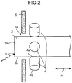
Fig. 2] Fig. 2 is a diagram showing a target and magnets ofFig. 1 as viewed from the side surface of the target. - [
Fig. 3] Fig. 3 is a diagram showing the target and magnets ofFig. 1 as viewed from the front end surface of the target. - [
Fig. 4] Fig. 4 is a diagram showing a magnetic field generated by the magnets ofFig. 1 . - [
Fig. 5] Fig. 5 is a diagram of an enlarged portion between a target front end surface and a magnet in the magnetic field ofFig. 4 . - [
Fig. 6] Fig. 6 is a graph showing the relationship between distance from the front end surface of the target ofFig. 1 and horizontal magnetic flux density. - [
Fig. 7] Fig. 7 is a graph showing the relationship between distance from the front end surface of the target ofFig. 1 and the angle of magnetic lines of force with respect to the side surface of the target. - [
Fig. 8] Fig. 8 is a diagram of an enlarged portion between a target front end surface and a magnet in a variation of the present invention, where magnets are disposed so as to align the magnetic poles thereof in the axial direction of the target. - [
Fig. 9] Fig. 9 is a diagram showing a state in which magnets with different magnetic poles aligned in the axial direction of the target generate a magnetic field not satisfying magnetic field generation conditions a) and b) according to the present invention, as a comparative example of the present invention. - [
Fig. 10] Fig. 10 is a graph showing the relationship between distance from the front end surface of the target ofFig. 9 and horizontal magnetic flux density. - [
Fig. 11] Fig. 11 is a graph showing the relationship between distance from the front end surface of the target ofFig. 9 and the angle of magnetic lines of force with respect to the side surface of the target. - There will be described below embodiments of the arc evaporation source of the present invention more specifically with reference to accompanying drawings.
-
Figs. 1 to 3 show anarc evaporation source 1, which includes: amain body 2; a rod-shaped target 3 made of carbon; a plurality ofmagnets 4 disposed around thetarget 3 in a radial arrangement; ashield plate 5 that protects themagnets 4 against arc discharge; afeeding unit 6 that feeds thetarget 3 in the axial direction A; and anignition device 7 that initiates arc discharge at thetarget 3. - The
main body 2 has amain plate 2a and acylindrical portion 2b. Themain plate 2a is disposed inside a chamber (not shown) of a film-forming apparatus. Thecylindrical portion 2b is disposed outside the chamber, on the back side of themain plate 2a. The front end portion of the rod-shaped target 3 passes through themain plate 2a and theshield plate 5 to be exposed inside the chamber. Theremaining portion 3c of thetarget 3 is accommodated inside thecylindrical portion 2b. Theshield plate 5 has a through-hole 5a through which thetarget 3 passes. - The rod-
shaped target 3, which is made of carbon, is cylindrical, specifically having a circularfront end surface 3a and aside surface 3b that is continuous with the peripheral edge of thefront end surface 3a. Thetarget 3 has a diameter of about 10 to 30 mm. The length of thetarget 3 is sufficiently greater than the diameter of thetarget 3. In the case of atarget 3 made of carbon, an arc spot S (seeFig. 2 ) rotates slowly (one rotation per several seconds) within the circular targetfront end surface 3a, thus not tending to move randomly within the front end surface as in the case of a metallic target. Hence, in the case of a carbon-made target with a large diameter and a shape similar to flat plate, the film thickness distribution during film formation may be brought into unevenness, causing a possibility that the front end surface is prevented from uniform consummation while only a corner part thereof is consumed. To solve this problem, it is preferable that the diameter of thetarget 3 is about 10 to 30 mm, as described above, in the case of a carbon-made target. - It is also possible that the
target 3 has a shape other than a rod-shaped shape (for instance, various three-dimensional shapes wherein the length of thetarget 3 is not sufficiently larger than the diameter of thetarget 3, for example as in a plate-like shape). - The
target 3 is made of a material containing carbon; for example, it can be produced from a pure carbon substance, or from a mixture of carbon with other substances. - The
target 3 is melted and vaporized from thefront end surface 3a by arc discharge in the chamber of the film-forming apparatus, in order to deposit a film on the surface of a substrate. The arc discharge is initiated when acontact bar 7a of theignition device 7 comes into contact with thetarget 3. Thetarget 3 is automatically fed by thefeeding unit 6 in the axial direction A perpendicular to thefront end surface 3a, so as to protrude into the chamber by a length equal to the length of the molten part of the target. This allows thefront end surface 3a of thetarget 3 to be maintained at a predetermined position regardless of the consummation of thetarget 3. - When vaporized by arc discharge, the
target 3 made of carbon used in the present embodiment involves less temperature increase, as compared with targets made up of other materials (for instance metals). Thearc evaporation source 1, therefore, requires no mechanism for cooling thetarget 3. Meanwhile, the target is also permitted to be made of a material other than carbon (for instance, a metal-made target of tungsten carbide or the like described below). - Each of the plurality of
magnets 4 hasmagnetic poles magnets 4 are disposed so as to align themagnetic poles target 3, at respective positions apart from theside surface 3b of thetarget 3 in the radial direction B of thetarget 3. Themagnets 4 generate a magnetic field MF1 (Figs. 4 to 5 ) that satisfies conditions a) and b) described below. Each of themagnetic pole 4a opposed to theside surface 3b of thetarget 3 is an N-pole, while each of themagnetic pole 4b facing outward in the radial direction B of thetarget 3 is an S-pole. - The plurality of
magnets 4 are attached to themain plate 2a of themain body 2 so as to be spaced at regular intervals in the circumferential direction of thetarget 3. This makes it possible to distribute a magnetic field MF1 generated by themagnets 4 uniformly in the circumferential direction of thetarget 3, on theside surface 3b of thetarget 3. - The
magnets 4 are disposed on a rear side of thefront end surface 3a of thetarget 3, in the axial direction A of thetarget 3. For instance, as shown inFig. 4 , themagnets 4 are disposed so as to locate their respective centers atrespective positions 20 mm rearward (rightward inFig. 4 ) apart from thefront end surface 3a of thetarget 3. This makes it possible to surely generate a magnetic field MF1 satisfying conditions a) and b) described below and further to allay adhesion, onto themagnets 4, of molten material flying off thefront end surface 3a of thetarget 3. Themagnets 4 does not have to be disposed on the rear side of thefront end surface 3a of thetarget 3 in the axial direction A of thetarget 3, if being capable of forming the magnetic field MF1 that satisfies conditions a) and b). For instance, it is also allowable that a part of themagnet 4 projects frontward (specifically, in the direction in which thefront end surface 3a inFig. 4 faces (leftward direction inFig. 4 )) beyond thefront end surface 3a. - As shown in
Fig. 2 , there is ashield plate 5 interposed between thefront end surface 3a of the target and themagnets 4. - Each of the
magnets 4 is formed of a permanent magnet that generates strong magnetic forces; for instance, it can be produced of an alloy that contains neodymium (for example, NdFeB). Permanent magnets containing neodymium, in spite of their small sizes, can generate strong magnetic lines of force FL1 that satisfy conditions a) and b) described below. Permanent magnets that generate strong magnetic forces are produced also of alloys containing samarium and cobalt (SmCo). - The
magnets 4, each being made of a permanent magnet, is allowed to be downsized than electromagnets having coils. This increases a degree of flexibility in arrangement of themagnets 4 and allows downsizing of thearc evaporation source 1 to be more reliably achieved. - The
magnets 4, being disposed in a radial arrangement apart from theside surface 3b of thetarget 3 so as to align themagnetic poles Figs. 4 to 5 on theside surface 3b of thetarget 3. InFig. 4 themagnets 4 are disposed on the rear side of thefront end surface 3a of thetarget 3; specifically, disposed so as to locate their respective centers atrespective positions 20 mm rearward apart from thefront end surface 3a of thetarget 3. However, the positional relationship of themagnets 4 with respect to thefront end surface 3a according to the present invention is not limited to that. - The magnetic lines of force FL1 of the magnetic field MF1 exit the
magnetic poles 4a opposed to theside surface 3b of thetarget 3 and extend at an acute angle (specifically, acute angle of 45 degrees or less inFigs. 4 to 5 ) with respect to theside surface 3b of thetarget 3, in the vicinity of thefront end surface 3a withinside surface 3b of the target 3 (specifically, in a region of up to 10 mm from thefront end surface 3a of the target 3). In summary, the magnetic lines of force FL1 extend outward in the radial direction B while approaching thefront end surface 3a of thetarget 3 in theside surface 3b of thetarget 2, in a region of up to 10 mm from thefront end surface 3a. Furthermore, in this region, the magnetic lines of force FL1 keep their high density (i.e., the magnetic flux density thereof is high). - The magnetic field MF1 satisfies, in a region of up to 10 mm from the
front end surface 3a of thetarget 3 in the axial direction A of thetarget 3, the following conditions a) and b): - a) an angle θ which the magnetic lines of force FL1 of the magnetic field MF1 forms with the
side surface 3b of thetarget 3 is of 45 degrees or less; and - b) a component Bx of the strength of the magnetic lines of force FL1 along the axial direction A of the
target 3 is 200 G or more. - Satisfying the above conditions a) and b), the magnetic lines of force FL1 (
Figs. 4 to 5 ) on theside surface 3b of thetarget 3, in the vicinity of thefront end surface 3a of thetarget 3, i.e., in a region of up to 10 mm from thefront end surface 3a, act on the arc spot S so as to push back the arc spot S into the area of thefront end surface 3a, even when the arc spot S shown inFigs. 2 to 3 tends to deviate from the area of thefront end surface 3a of thetarget 3 made of carbon. The arc spot S is thereby constrained within the area of thefront end surface 3a of thetarget 3 made of carbon, being prevented from deviating from the area of thefront end surface 3a of thetarget 3. - Furthermore, being disposed so as to generate a magnetic field that satisfies conditions a) and b) above, each of the
individual magnets 4 is not required to be upsized for generating strong magnetic forces. This makes it possible to restrict upsizing thearc evaporation source 1. - Besides, the
target 3 being rod-shaped allows film formation to be performed continuously over a prolonged period of time corresponding to the length of thetarget 3. - In the present embodiment using a carbon-made target as the
target 3, the arc spot S makes a more unstable movement to thus tend to deviate from thefront end surface 3a of the arc spot S. However, themagnets 4 generating a magnetic field that satisfies conditions a) and b) above allows the arc spot S to be retained stably on thefront end surface 3a of thetarget 3 in spite of use of the carbon-madetarget 3. - For generating the magnetic field MF1 satisfying conditions a) and b) of the present embodiment, the plurality of
magnets 4 according to the present embodiment are disposed so as to align mutually differentmagnetic poles magnets 4 in the radial direction B of thetarget 3, on the side of thetarget 3 made of carbon. This allows each of themagnets 4 to be small even though strong magnetic lines of force FL1 at an acute angle of 45 degrees or less with respect to theside surface 3b of thetarget 3 should be generated, thereby enabling the whole apparatus of thearc evaporation source 1 to be reliably downsized. - It is also permissible to dispose the
magnets 4 so as to align themagnetic poles 4a (for instance N-poles) and themagnetic poles 4b (for instance S-poles) of mutually different polarities in the axial direction A of thetarget 3, as shown inFig. 8 . In this case as well, disposing themagnets 4 so as to generate a magnetic field MF1' satisfying conditions a) and b) above allows the magnetic lines of force FL1' on theside surface 3b of thetarget 3 in the vicinity of thefront end surface 3a of thetarget 3, i.e., in a region of up to 10 mm from thefront end surface 3a, to act on the arc spot S so as to push back the arc spot S into the area of thefront end surface 3a even when the arc spot S tends to deviate from the area of thefront end surface 3a of the carbon-madetarget 3. Furthermore, each of themagnets 4 shown inFig. 8 is capable of generating a strong magnetic force, thus not being required to be upsized in order to generate strong magnetic forces. This makes it possible to restrict upsizing of thearc evaporation source 1. Thus aligning themagnetic poles target 3 causes electrons emitted from thefront end surface 3a of thetarget 3 to flow towards themagnetic poles 4a near thefront end surface 3a, along the magnetic lines of force FL1', thereby heating up the portions of themagnetic poles 4a of themagnets 4 as anodes; therefore, it is preferable to cool the portions of themagnetic poles 4a by a cooling mechanism relying for instance on water cooling. - In the case where the
magnets 4 are disposed so as to align themagnetic poles 4a and themagnetic poles 4b of mutually different polarities in the axial direction A of thetarget 3, as described above, it is also permissible to form themagnets 4 into a ring shape or to dispose a plurality ofmagnets 4 circumferentially around thetarget 3, as shown inFig. 8 . Only one of above ring-shaped magnet is required; thus, it is permissible that the ring-shaped magnet is just single. - Preferably, the component Bx of the strength of the magnetic lines of force FL1 along the axial direction A of the
target 3 is 500 G or more. Such magnetic lines of force FL1 is able to push back more reliably the arc spot S into the area of thefront end surface 3a of thetarget 3 made of carbon. - The above-described Conditions a) and b) will be explained below in further detail.
-
Fig. 6 depicts a graph showing the relationship, in the case of disposing themagnets 4 in a radial arrangement as shown inFig. 4 , between the distance X (mm) from thefront end surface 3a of the target ofFig. 1 and a horizontal magnetic flux density Bx (units G (= × 10-4 T)) of the magnetic field MF1 that is formed by themagnets 4. InFig. 6 , the component Bx of the axial direction A of thetarget 3 in the strength of the magnetic lines of force FL1 is indicated as the horizontal magnetic flux density Bx. - The curve I in the graph of
Fig. 6 represents the horizontal magnetic flux density Bx of themagnets 4 of the present embodiment made up of permanent magnets produced by use of an alloy (NdFeB) containing neodymium. The curve I represents a horizontal magnetic flux density Bx of 200 G or more, specifically a horizontal magnetic flux density Bx of 230 to 800 G, in a region of 0 to 10 mm of the distance X from thefront end surface 3a of thetarget 3. This teaches that strong magnetic lines of force enough to push back the arc spot S to thefront end surface 3a are generated in the region. Besides, the curve I represents a horizontal magnetic flux density Bx of 800 G or more in the region of distance X from 10 to 16 mm, thus teaching that very strong magnetic lines of force are generated in the region. In this region, the magnetic lines of force is so strong that the arc spot S can be pushed back more reliably, by magnetic forces, to thefront end surface 3a. - The curve II of the graph of
Fig. 6 represents the horizontal magnetic flux density Bx of themagnets 4 of the present embodiment made up of permanent magnets produced by use of an alloy of samarium and cobalt (SmCo). The curve II represents a horizontal magnetic flux density Bx of 200 G or more, specifically 210 to 620 G, in a region of 0 to 10 mm of the distance X from thefront end surface 3a of thetarget 3, thus teaching that there are generated, in the region, strong magnetic lines of force capable of pushing back the arc spot S to thefront end surface 3a. Besides, the curve II depicts a horizontal magnetic flux density Bx of 800 G or more in a region of 13 to 14 mm of the distance X. - In the region of 0 to 14 mm of the distance X from the
front end surface 3a of thetarget 3 in the curves I and II of the graph ofFig. 6 , the component Bx of the strength of the magnetic lines of force FL1 along the axial direction A of thetarget 3 increases with increase in distance from thefront end surface 3a of thetarget 3 in the axial direction A of thetarget 3. The magnetic lines of force FL1 thereby become stronger with increase in the distance from thefront end surface 3a of thetarget 3 in the axial direction A of thetarget 3. This makes it possible to reliably push back the arc spot S to thefront end surface 3a of thetarget 3 so as to inhibit the arc spot S from remaining on theside surface 3b, by the action of magnetic forces, even when the arc spot S has deviated from thefront end surface 3a of thetarget 3 towards theside surface 3b of thetarget 3. - In other words, the effect of pushing back the arc spot S on the
side surface 3b of the carbon-madetarget 3 greatly relies on the horizontal component strength Bx of the magnetic lines of force FL1. If there exists a place where the horizontal component strength Bx on theside surface 3b is locally weak, the arc spot S in the place is likely to make unintended behavior, and the position of the arc spot S becomes hard to control. Therefore, if distributed so that the horizontal component strength Bx of the magnetic lines of force FL1 increases uniformly in a monotonic fashion, the magnetic lines of force FL1 can reliably push back the arc spot S to thefront end surface 3a of thetarget 3. - In addition, the curve III of the graph of
Fig. 6 represents, as a reference example, the horizontal magnetic flux density Bx of a magnet made up of an existing permanent magnet containing iron (Fe) as a main starting material. A comparison of curve III versus curves I, II reveals that the horizontal magnetic flux density Bx is lower in a whole region of 0 to 20 mm of the distance X from thefront end surface 3a of thetarget 3. The horizontal magnetic flux density Bx is 200 G or less in the greater part of the region of 0 to 10 mm of the distance X, which teaches that such existing permanent magnets made of iron is incapable of yielding magnetic lines of force strong enough to push back the arc spot S to thefront end surface 3a. -
Fig. 7 depicts a graph showing the relationship, in the case of the radial arrangement of themagnets 4 as shown inFig. 4 , between the distance X (mm) from thefront end surface 3a of thetarget 3 inFig. 1 and the angle θ of the magnetic lines of force FL1 with respect to theside surface 3b of thetarget 3. The graph ofFig. 7 reveals that the angle θ lies within an acute angle range from 0 to 30 degrees, in a region of 0 to 12 mm of the distance X from thefront end surface 3a of thetarget 3, the magnetic lines of force FL1 having an angle acute enough to push back the arc spot S to thefront end surface 3a. - As described above, the experiments made by the inventors have confirmed that the configuration where
magnets 4 made up of permanent magnets produced by use of an alloy containing neodymium (NdFeB) or of an alloy containing samarium and cobalt (SmCo) are disposed in a radial arrangement as shown inFigs. 4 to 5 can generate magnetic lines of force MF1 that satisfy conditions a) and b) above to thereby prevent the arc spot S from deviating from the area of thefront end surface 3a of thetarget 3. - Besides, next will be contemplated, as a conceivable comparative example of the present invention, a configuration which generates a magnetic field that does not satisfy the above conditions a) or b) above, which are magnetic field generation conditions of the present invention, in the case where
magnets 104 made up of permanent magnets are disposed in the axial direction A of thetarget 3 as shown inFig. 9 . - In the configuration shown in
Fig. 9 , themagnets 104 are disposed apart from theside surface 3b of thetarget 3 and so as to alignmagnetic poles target 3. This allows themagnets 104 to generate a magnetic field MF2 shown inFig. 9 on theside surface 3b of thetarget 3. InFig. 9 , themagnets 104 are disposed so as to locate the axially center of themagnets 104 at aposition 20 mm rearward from thefront end surface 3a of thetarget 3. - The magnetic lines of force FL2 of the magnetic field MF2, though exiting the
magnetic poles 104a facing thefront end surface 3a of thetarget 3, penetrate into thetarget 3 through theside surface 3b of thetarget 3 in the vicinity of thefront end surface 3a on theside surface 3b of the target 3 (specifically, in a region of up to about 6 mm from thefront end surface 3a of the target 3). In summary, the magnetic lines of force FL2 extend inward in the radial direction B while approaching thefront end surface 3a of thetarget 2, on theside surface 3b, in a region of up to about 6 mm from thefront end surface 3a of thetarget 3. In addition, the magnetic lines of force FL2 are sparse (i.e., the magnetic flux density is low) in the region. -
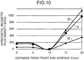
Fig. 10 depicts a graph showing the relationship, in the case where themagnets 104 are disposed in the axial direction of thetarget 3 as shown inFig. 9 , between the distance X (mm) from thefront end surface 3a of thetarget 3 and the horizontal magnetic flux density Bx (units G (= × 10-4 T)) of the magnetic field MF2 that is formed by themagnets 4. - The curve IV in the graph of
Fig. 10 represents the horizontal magnetic flux density Bx of themagnets 104 made up of permanent magnets produced by use of an alloy (NdFeB) containing neodymium. The curve V represents a horizontal magnetic flux density Bx of themagnets 104 made up of permanent magnets produced by use of an alloy of samarium and cobalt (SmCo). The curve VI represents the horizontal magnetic flux density Bx of themagnets 104 made up of permanent magnets containing iron (Fe) as a main starting material. - The curves IV to VI reveal that the horizontal magnetic flux density Bx is kept at a low value smaller than 200 G in a region of 0 to 10 mm of the distance X from the
front end surface 3a of thetarget 3. In the region, since the strength of the magnetic lines of force FL2 is thus small, the arc spot S seems to be hard to push back to thefront end surface 3a. -
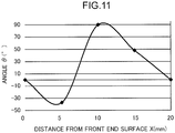
Fig. 11 depicts a graph showing the relationship, in the case where themagnets 104 are disposed in the axial direction of thetarget 3 as shown inFig. 9 , between the distance X (mm) from thefront end surface 3a of thetarget 3 and the angle θ of the magnetic lines of force FL2 with respect to theside surface 3b of thetarget 3. As can be grasped from the graph ofFig. 11 , the angle θ is 0 degrees or smaller in a region of 0 to 6 mm of the distance X from thefront end surface 3a of thetarget 3. In summary, the magnetic lines of force FL2 extend inward in the radial direction B while approaching thefront end surface 3a to penetrate into thetarget 3, on theside surface 3b of thetarget 3, in a region of up to 6 mm from thefront end surface 3a of thetarget 3. Hence, it is deemed that the magnetic lines of force FL2 that penetrate into thetarget 3 elicit a weak action of pushing back the arc spot S to thefront end surface 3a, on theside surface 3b of thetarget 3. - It is thus found that disposing the
magnets 104 in the axial direction A of thetarget 3 as shown inFig. 9 makes it difficult to construct a configuration in which the magnetic field MF2 formed by themagnets 104 satisfies the above conditions a) and b) in a region of up to 10 mm from thefront end surface 3a of thetarget 3 in the axial direction A of thetarget 3. It is accordingly deemed that it is difficult to push back the arc spot S into the area of thefront end surface 3a of thetarget 3 by the magnetic lines of force FL2 on theside surface 3b of thetarget 3 in the case of not satisfying the above conditions a) or b) as shown inFigs. 9 to 11 . - Furthermore, the experiments made by the inventors have confirmed that the configuration where
such magnets 104 are disposed in the axial direction A of thetarget 3 is incapable of preventing the arc spot S from deviating from the area of thefront end surface 3a of thetarget 3, differently from the configuration shown inFigs. 4 to 5 of the present embodiment where themagnets 4 are disposed in a radial arrangement, even using permanent magnets produced of an alloy containing neodymium (NdFeB) or an alloy containing samarium and cobalt (SmCo). - Therefore, it is found that satisfying the above magnetic field generation conditions a) and b) is more easily accomplished in a configuration where the
magnets 4 are disposed so as to align themagnetic poles target 3 as shown inFigs. 4 to 5 than in a configuration where themagnets 104 are disposed so as to align themagnetic poles target 3 as shown inFig. 9 . Accordingly, it is found that the configuration where themagnets 4 are disposed in a radial arrangement as shown inFigs. 4 to 5 is capable of constraining the arc spot S on thefront end surface 3a of thetarget 3 more stably and allowing thearc evaporation source 1 to be reliably achieved. - About the above embodiments, the explanation is made with taking a carbon-made target as an example of the
target 3; the present invention is, however, not limited thereto. Thetarget 3 is also permitted to contain tungsten carbide, tungsten, molybdenum or niobium. Also on atarget 3 made of tungsten carbide or the like, an arc spot tends to make an unstable movement similarly to the case of the above carbon-madetarget 3. However, the generation of a magnetic field that satisfies the conditions a) and b) by the magnets as described above makes it possible to stably retain the arc spot on the front end surface of thetarget 3 even with use of a carbon-madetarget 3. Since atarget 3 made of tungsten carbide or the like is expensive, the consummation pattern and the yield of thetarget 3 are of great concern. The use of tungsten carbide or the like as the rod-shapedtarget 3 for thearc evaporation source 1 is effective in making the consumption of thetarget 3 uniform (that is, allowing thetarget 3 to be consumed uniformly over the entire front end surface thereof) and in enhancing yield. - In the above-described specific embodiments, mainly lies an invention having the features below.
- The arc evaporation source according to the present embodiment includes:
- a target to be melted and evaporated from a front end surface of the target by arc discharge; and
- at least one magnet disposed at a position apart from a side surface of the target radially of the target, the side surface being continuous with a periphery of the front end surface of the target,
- wherein the magnet is disposed so as to form a magnetic field that satisfies conditions a) and b) below, on the side surface of the target, in a region of up to 10 mm from the front end surface of the target in an axial direction of the target, the axial direction being normal to the front end surface:
- a) an angle which magnetic lines of force of the magnetic field forms with the side surface of the target is 45 degrees or less; and
- b) a component of the strength of the magnetic lines of force along the axial direction of the target is 200 G or more.
- According to the above configuration, the magnetic field generated by the magnet satisfying the above conditions a) and b) above, allows the magnetic lines of force on the side surface of the target in the vicinity of the front end surface of the target, i.e., in a region of up to 10 mm from the front end surface, to act on the arc spot so as to push back the arc spot back into the area of the front end surface even when the arc spot tends to deviate from the area of the front end surface of the target. The arc spot is thereby constrained within the area of the front end surface of the target.
- Furthermore, disposing the magnet so as to generate a magnetic field that satisfies the above conditions a) and b) eliminates the need for upsizing the magnet in order to generate strong magnetic forces. This allows upsizing the apparatus to be restricted.
- Preferably, the target is rod-shaped. This allows film deposition to be performed continuously over a prolonged period of time corresponding to the length of the rod-shaped target.
- The target may contain carbon. According to a carbon-made target, the arc spot makes a more unstable movement, tending to deviate from the front end surface of the arc spot. However, the generation of the magnetic field satisfying the above conditions a) and b) by the magnet makes it possible to retain the arc spot stably on the front end surface of the target even with use of a carbon-made target.
- The target may contain tungsten carbide, tungsten, molybdenum or niobium. Also on a target made of tungsten carbide or the like, the arc spot tends to make an unstable movement, as is the case of the above carbon-made target. However, the above-described generation of the magnetic field satisfying the above conditions a) and b) by the magnet makes it possible to retain the arc spot stably on the front end surface of the target, even with the use of a target made of tungsten carbide or the like. Since a target made of tungsten carbide or the like is expensive, especially the consummation pattern and the yield of the target are of great concern. The use of tungsten carbide or the like as the rod-shaped target for the arc evaporation source is effective in making the consumption of the target uniform and in enhancing yield.
- Preferably, the magnet has magnetic poles of mutually different polarities, and the magnet is disposed so as to align the magnetic poles of mutually different polarities in the radial direction of the target. In the case where the magnet is disposed so as to align the mutually different magnetic poles in the radial direction of the target, on the side of the target, as the arrangement of the magnet for generating the magnetic field that satisfies conditions a) and b), one of the magnetic poles of the magnet is opposed to the side surface of the target while the other magnetic pole faces outward in the radial direction of the target. This enables the magnetic pole opposed to the side surface of the target to generate, on the side surface of the target, such strong magnetic lines of force at an acute angle of 45 degrees or less as to satisfy the above conditions a) and b), in a region of up to 10 mm from the front end surface. In other words, disposing the magnets in the above way allows the individual magnet to be small while still generating strong magnetic lines of force at an acute angle of 45 degrees or less with respect to the side surface of the target, thus allowing the whole apparatus of the arc evaporation source to be reliably downsized.
- It is also permissible that the magnet have magnetic poles of mutually different polarities and the magnet is disposed so as to align the magnetic poles of mutually different polarities in the axial direction of the target. Also in this case, disposing the magnets so as to generate a generate strong magnetic forces field that satisfies conditions a) and b) eliminates the need for upsizing the magnet, which is enabled to generate a strong magnetic force. This allows upsizing an apparatus to be restricted.
- The component of the strength of the magnetic lines of force along the axial direction of the target is preferably 500 G or more.
- Such magnetic lines of force is capable of pushing back the arc spot more reliably into the area of the front end surface of the target.
- The component of the strength of the magnetic lines of force along the axial direction of the target is preferably increased with increase in distance from the front end surface of the target in the axial direction of the target.
- According to this configuration, the magnetic lines of force become stronger with increase in distance from the front end surface of the target in the axial direction of the target. This makes it possible to push back the arc spot reliably to the front end surface by the action of magnetic forces so as to inhibit the arc spot from remaining on the side surface, even when the arc spot has deviated from the front end surface of the target to the side surface of the target.
- Preferably, the magnetic field has a place at which the component of the strength of the magnetic lines of force along the axial direction of the target is 800 G or more, on the side surface of the target, in a region of up to 20 mm from the front end surface of the target in the axial direction of the target.
- This configuration makes it possible to push back the arc spot more reliably to the target front end surface through the action of magnetic forces so as to inhibit the arc spot from remaining on the side surface of the target.
- The magnet is preferably a permanent magnet.
- This allows the magnet to be downsized than an electromagnet having a coil. This allows degree of the flexibility of arrangement of the magnet to be increased and allow downsizing of the arc evaporation source to be achieved more reliably.
- The permanent magnet preferably contains neodymium.
- The permanent magnets containing neodymium is able to generate strong magnetic lines of force that satisfy the above conditions a) and b) despite its small size.
- Preferably, a plurality of the magnets are spaced at regular intervals in a circumferential direction of the target.
- This allows the magnetic field generated by the magnets to be distributed uniformly in the circumferential direction of the target, on the target side surface, thus making it possible to eliminate portions where the magnetic lines of force are locally weak to cause a possibility of permitting the arc spot to remain on the side surface of the target. This results in the ability to push back the arc spot to the target front end surface more reliably, through the action of magnetic forces.
- The magnet is preferably disposed on a rear side of the front end surface of the target, in the axial direction of the target.
- Thus disposing the magnets makes it possible to reliably generate a magnetic field that satisfies the above conditions a) and b) and further to allay the concern of adhesion, onto the magnets, of molten material flying off the front end surface of the target.
Claims (13)
- An arc evaporation source, comprising:a target to be melted and evaporated from a front end surface of the target by arc discharge; andat least one magnet disposed at a position apart from a side surface of the target radially of the target, the side surface being continuous with a periphery of the front end surface of the target,wherein the magnet is disposed so as to form a magnetic field that satisfies conditions a) and b) below, on the side surface of the target, in a region of up to 10 mm from the front end surface of the target in an axial direction of the target, the axial direction being normal to the front end surface:a) an angle which magnetic lines of force of the magnetic field forms with the side surface of the target is 45 degrees or less; andb) a component of the strength of the magnetic lines of force along the axial direction of the target is 200 G or more.
- The arc evaporation source according to claim 1, wherein the target is rod-shaped.
- The arc evaporation source according to claim 1, wherein the target contains carbon.
- The arc evaporation source according to claim 1, wherein the target contains tungsten carbide, tungsten, molybdenum or niobium.
- The arc evaporation source according to claim 1, wherein
the magnet has magnetic poles of mutually different polarities, and
the magnet is disposed so as to align the magnetic poles of mutually different polarities in the radial direction of the target. - The arc evaporation source according to claim 1, wherein
the magnet has magnetic poles of mutually different polarities, and
the magnet is disposed so as to align the magnetic poles of mutually different polarities in the axial direction of the target. - The arc evaporation source according to claim 1,
wherein the component of the strength of the magnetic lines of force along the axial direction of the target is 500 G or more. - The arc evaporation source according to claim 1,
wherein the component of the strength of the magnetic lines of force along the axial direction of the target is increased with increase in distance from the front end surface of the target in the axial direction of the target. - The arc evaporation source according to claim 1,
wherein the magnetic field has a place at which the component of the strength of the magnetic lines of force along the axial direction of the target is 800 G or more, on the side surface of the target, in a region of up to 20 mm from the front end surface of the target in the axial direction of the target. - The arc evaporation source according to claim 1,
wherein the magnet is a permanent magnet. - The arc evaporation source according to claim 10,
wherein the permanent magnet contains neodymium. - The arc evaporation source according to claim 1,
wherein a plurality of the magnets are spaced at regular intervals in a circumferential direction of the target. - The arc evaporation source according to claim 1,
wherein the magnet is disposed on a rear side of the front end surface of the target, in the axial direction of the target.
Applications Claiming Priority (3)
| Application Number | Priority Date | Filing Date | Title |
|---|---|---|---|
| JP2014154722 | 2014-07-30 | ||
| JP2015036107A JP6403269B2 (en) | 2014-07-30 | 2015-02-26 | Arc evaporation source |
| PCT/JP2015/069340 WO2016017374A1 (en) | 2014-07-30 | 2015-07-03 | Arc evaporation source |
Publications (3)
| Publication Number | Publication Date |
|---|---|
| EP3156516A4 EP3156516A4 (en) | 2017-04-19 |
| EP3156516A1 true EP3156516A1 (en) | 2017-04-19 |
| EP3156516B1 EP3156516B1 (en) | 2019-12-18 |
Family
ID=55217279
Family Applications (1)
| Application Number | Title | Priority Date | Filing Date |
|---|---|---|---|
| EP15827912.5A Active EP3156516B1 (en) | 2014-07-30 | 2015-07-03 | Arc evaporation source |
Country Status (11)
| Country | Link |
|---|---|
| US (1) | US10913997B2 (en) |
| EP (1) | EP3156516B1 (en) |
| JP (1) | JP6403269B2 (en) |
| KR (1) | KR101943725B1 (en) |
| CN (1) | CN106460159B (en) |
| BR (1) | BR112016030966B1 (en) |
| ES (1) | ES2764281T3 (en) |
| IL (1) | IL249422B (en) |
| MX (1) | MX382008B (en) |
| PT (1) | PT3156516T (en) |
| WO (1) | WO2016017374A1 (en) |
Families Citing this family (3)
| Publication number | Priority date | Publication date | Assignee | Title |
|---|---|---|---|---|
| CN110158038B (en) | 2014-03-18 | 2022-01-18 | 佳能安内华股份有限公司 | Deposition apparatus |
| CN107881478B (en) * | 2017-11-30 | 2024-02-27 | 嘉兴岱源真空科技有限公司 | Arc ignition device and nano material manufacturing equipment |
| JP7739250B2 (en) * | 2022-11-07 | 2025-09-16 | 株式会社神戸製鋼所 | Arc evaporation source |
Family Cites Families (54)
| Publication number | Priority date | Publication date | Assignee | Title |
|---|---|---|---|---|
| AT376460B (en) * | 1982-09-17 | 1984-11-26 | Kljuchko Gennady V | PLASMA ARC DEVICE FOR APPLYING COVERS |
| US4556471A (en) * | 1983-10-14 | 1985-12-03 | Multi-Arc Vacuum Systems Inc. | Physical vapor deposition apparatus |
| WO1987005948A1 (en) * | 1986-04-04 | 1987-10-08 | Regents Of The University Of Minnesota | Arc coating of refractory metal compounds |
| JP2537210B2 (en) * | 1986-09-18 | 1996-09-25 | 株式会社東芝 | High-density plasma generator |
| US4767931A (en) * | 1986-12-17 | 1988-08-30 | Hitachi, Ltd. | Ion beam apparatus |
| DE3700633C2 (en) * | 1987-01-12 | 1997-02-20 | Reinar Dr Gruen | Method and device for the gentle coating of electrically conductive objects by means of plasma |
| DE4017111C2 (en) * | 1990-05-28 | 1998-01-29 | Hauzer Holding | Arc magnetron device |
| JPH04221064A (en) | 1990-12-21 | 1992-08-11 | Nkk Corp | Vacuum arc generator and ion beam generator using the same |
| JP3221892B2 (en) * | 1991-09-20 | 2001-10-22 | 帝国ピストンリング株式会社 | Piston ring and its manufacturing method |
| US5279723A (en) * | 1992-07-30 | 1994-01-18 | As Represented By The United States Department Of Energy | Filtered cathodic arc source |
| US5480527A (en) * | 1994-04-25 | 1996-01-02 | Vapor Technologies, Inc. | Rectangular vacuum-arc plasma source |
| JP3287163B2 (en) * | 1995-01-23 | 2002-05-27 | 日新電機株式会社 | Arc evaporation source |
| GB9722645D0 (en) * | 1997-10-24 | 1997-12-24 | Univ Nanyang | Enhanced macroparticle filter and cathode arc source |
| SE511139C2 (en) * | 1997-11-20 | 1999-08-09 | Hana Barankova | Plasma processing apparatus with rotatable magnets |
| IL127236A0 (en) * | 1997-11-26 | 1999-09-22 | Vapor Technologies Inc | Apparatus for sputtering or arc evaporation |
| US6103074A (en) * | 1998-02-14 | 2000-08-15 | Phygen, Inc. | Cathode arc vapor deposition method and apparatus |
| TWI242049B (en) * | 1999-01-14 | 2005-10-21 | Kobe Steel Ltd | Vacuum arc evaporation source and vacuum arc vapor deposition apparatus |
| US6929727B2 (en) * | 1999-04-12 | 2005-08-16 | G & H Technologies, Llc | Rectangular cathodic arc source and method of steering an arc spot |
| US6440282B1 (en) * | 1999-07-06 | 2002-08-27 | Applied Materials, Inc. | Sputtering reactor and method of using an unbalanced magnetron |
| JP2001152319A (en) * | 1999-11-25 | 2001-06-05 | Kohan Kogyo Kk | Surface treated metallic member having surface treatment layer excellent in adhesion, surface treatment method therefor, and rotary equipment member using the surface treatment method |
| JP3860954B2 (en) * | 2000-07-07 | 2006-12-20 | 株式会社日立グローバルストレージテクノロジーズ | Plasma processing apparatus with real-time particle filter |
| JP4371569B2 (en) * | 2000-12-25 | 2009-11-25 | 信越化学工業株式会社 | Magnetron sputtering apparatus and photomask blank manufacturing method using the same |
| ATE277204T1 (en) * | 2001-03-27 | 2004-10-15 | Fundacion Tekniker | ARC EVAPORATION WITH POWERFUL MAGNETIC GUIDANCE FOR LARGE SURFACE TARGET |
| SE525231C2 (en) * | 2001-06-14 | 2005-01-11 | Chemfilt R & D Ab | Method and apparatus for generating plasma |
| US7411352B2 (en) * | 2002-09-19 | 2008-08-12 | Applied Process Technologies, Inc. | Dual plasma beam sources and method |
| JP5160730B2 (en) * | 2002-09-19 | 2013-03-13 | ジェネラル・プラズマ・インコーポレーテッド | Beam plasma source |
| US7147759B2 (en) * | 2002-09-30 | 2006-12-12 | Zond, Inc. | High-power pulsed magnetron sputtering |
| US6896773B2 (en) * | 2002-11-14 | 2005-05-24 | Zond, Inc. | High deposition rate sputtering |
| DE10256417A1 (en) * | 2002-12-02 | 2004-06-09 | Pvt Plasma Und Vakuum Technik Gmbh | Arc evaporation device |
| JP4989026B2 (en) * | 2002-12-19 | 2012-08-01 | エリコン・トレーディング・アクチェンゲゼルシャフト,トリュープバッハ | Vacuum arc source with magnetic field generator |
| JP4045953B2 (en) * | 2002-12-27 | 2008-02-13 | 日新電機株式会社 | Vacuum arc evaporation system |
| US7211138B2 (en) * | 2003-02-07 | 2007-05-01 | Kabushiki Kaisha Kobe Seiko Sho (Kobe Steel, Ltd.) | Hard film, method of forming the same and target for hard film formation |
| JP4438326B2 (en) * | 2003-06-13 | 2010-03-24 | 日新電機株式会社 | Deflection magnetic field type vacuum arc deposition system |
| SE0302045D0 (en) * | 2003-07-10 | 2003-07-10 | Chemfilt R & D Ab | Work piece processing by pulsed electric discharges in solid-gas plasmas |
| JP4827235B2 (en) * | 2005-09-07 | 2011-11-30 | 株式会社リケン | Arc type evaporation source and method for manufacturing film-formed body |
| ATE553495T1 (en) * | 2005-12-13 | 2012-04-15 | Oerlikon Solar Ag | IMPROVED SPUTTER TARGET USAGE |
| US20090050059A1 (en) * | 2005-12-16 | 2009-02-26 | Josu Goikoetxea Larrinaga | Cathode evaporation machine |
| EP1991037A1 (en) * | 2006-03-01 | 2008-11-12 | Shinmaywa Industries, Ltd. | Plasma gun and plasma gun film forming apparatus provided with same |
| US7498587B2 (en) * | 2006-05-01 | 2009-03-03 | Vapor Technologies, Inc. | Bi-directional filtered arc plasma source |
| RU2448388C2 (en) * | 2006-05-16 | 2012-04-20 | Эрликон Трейдинг Аг, Трюббах | Electroarc source and magnetic accessory |
| US7857948B2 (en) * | 2006-07-19 | 2010-12-28 | Oerlikon Trading Ag, Trubbach | Method for manufacturing poorly conductive layers |
| ES2648995T3 (en) * | 2007-04-17 | 2018-01-09 | Oerlikon Surface Solutions Ag, Pfäffikon | Evacuation source by vacuum arc, as well as an evaporation chamber by voltaic arc with a source of evaporation by vacuum arc |
| DE102007019982B4 (en) * | 2007-04-23 | 2011-02-17 | Fraunhofer-Gesellschaft zur Förderung der angewandten Forschung e.V. | Arrangement for the formation of coatings on substrates in a vacuum |
| JP4878020B2 (en) * | 2007-09-27 | 2012-02-15 | 株式会社神戸製鋼所 | Vacuum arc evaporation source |
| US8016982B2 (en) * | 2007-11-30 | 2011-09-13 | Panasonic Corporation | Sputtering apparatus and sputtering method |
| JP5037630B2 (en) * | 2007-12-18 | 2012-10-03 | キヤノンアネルバ株式会社 | Plasma processing equipment |
| DE102009008161A1 (en) * | 2009-02-09 | 2010-08-12 | Oerlikon Trading Ag, Trübbach | Modifiable magnet configuration for arc evaporation sources |
| JP5649308B2 (en) * | 2009-04-28 | 2015-01-07 | 株式会社神戸製鋼所 | Arc type evaporation source having high film forming speed and method for producing coating film using this arc type evaporation source |
| JP5318052B2 (en) * | 2010-06-23 | 2013-10-16 | 株式会社神戸製鋼所 | Arc type evaporation source having high film forming speed, film manufacturing method and film forming apparatus using this arc type evaporation source |
| JP5081320B2 (en) * | 2011-02-23 | 2012-11-28 | 株式会社神戸製鋼所 | Arc type evaporation source |
| JP5081315B2 (en) * | 2011-02-23 | 2012-11-28 | 株式会社神戸製鋼所 | Arc type evaporation source |
| KR20150103383A (en) * | 2011-02-23 | 2015-09-10 | 가부시키가이샤 고베 세이코쇼 | Arc evaporation source |
| JP5809476B2 (en) * | 2011-07-29 | 2015-11-11 | 新明和工業株式会社 | Film forming apparatus and film forming method |
| JP5946337B2 (en) * | 2012-06-20 | 2016-07-06 | 株式会社神戸製鋼所 | Arc type evaporation source |
-
2015
- 2015-02-26 JP JP2015036107A patent/JP6403269B2/en active Active
- 2015-07-03 PT PT158279125T patent/PT3156516T/en unknown
- 2015-07-03 WO PCT/JP2015/069340 patent/WO2016017374A1/en not_active Ceased
- 2015-07-03 BR BR112016030966-9A patent/BR112016030966B1/en not_active IP Right Cessation
- 2015-07-03 MX MX2017001286A patent/MX382008B/en unknown
- 2015-07-03 US US15/321,227 patent/US10913997B2/en not_active Expired - Fee Related
- 2015-07-03 KR KR1020167035899A patent/KR101943725B1/en active Active
- 2015-07-03 CN CN201580033266.9A patent/CN106460159B/en active Active
- 2015-07-03 ES ES15827912T patent/ES2764281T3/en active Active
- 2015-07-03 EP EP15827912.5A patent/EP3156516B1/en active Active
-
2016
- 2016-12-06 IL IL249422A patent/IL249422B/en active IP Right Grant
Also Published As
| Publication number | Publication date |
|---|---|
| JP6403269B2 (en) | 2018-10-10 |
| ES2764281T3 (en) | 2020-06-02 |
| IL249422B (en) | 2020-10-29 |
| EP3156516A4 (en) | 2017-04-19 |
| BR112016030966A2 (en) | 2018-07-17 |
| IL249422A0 (en) | 2017-02-28 |
| US20170204507A1 (en) | 2017-07-20 |
| BR112016030966B1 (en) | 2021-12-07 |
| JP2016033256A (en) | 2016-03-10 |
| KR101943725B1 (en) | 2019-01-29 |
| PT3156516T (en) | 2020-03-24 |
| MX382008B (en) | 2025-03-13 |
| KR20170008298A (en) | 2017-01-23 |
| CN106460159B (en) | 2019-03-05 |
| MX2017001286A (en) | 2017-05-10 |
| WO2016017374A1 (en) | 2016-02-04 |
| EP3156516B1 (en) | 2019-12-18 |
| CN106460159A (en) | 2017-02-22 |
| US10913997B2 (en) | 2021-02-09 |
Similar Documents
| Publication | Publication Date | Title |
|---|---|---|
| EP2788522B1 (en) | Filtered cathodic arc deposition apparatus and method | |
| US10913997B2 (en) | Arc evaporation source | |
| TWI242049B (en) | Vacuum arc evaporation source and vacuum arc vapor deposition apparatus | |
| JP2012517522A (en) | A modifiable magnetic array for arc evaporation sources | |
| US10982318B2 (en) | Arc evaporation source | |
| JP4548666B2 (en) | Evaporation source for arc ion plating equipment | |
| JP7739250B2 (en) | Arc evaporation source | |
| JP5648532B2 (en) | Arc ion plating equipment | |
| US20160099134A1 (en) | Arc evaporation coating source having a permanent magnet | |
| JPWO2011021281A1 (en) | Arc evaporation source and vacuum evaporation system | |
| US9818586B2 (en) | Arc evaporation source | |
| US9953808B2 (en) | Arc evaporation source | |
| JP2006111930A (en) | Film deposition system | |
| JP4684141B2 (en) | Vacuum arc evaporation source and vacuum arc evaporation apparatus |
Legal Events
| Date | Code | Title | Description |
|---|---|---|---|
| STAA | Information on the status of an ep patent application or granted ep patent |
Free format text: STATUS: THE INTERNATIONAL PUBLICATION HAS BEEN MADE |
|
| PUAI | Public reference made under article 153(3) epc to a published international application that has entered the european phase |
Free format text: ORIGINAL CODE: 0009012 |
|
| STAA | Information on the status of an ep patent application or granted ep patent |
Free format text: STATUS: REQUEST FOR EXAMINATION WAS MADE |
|
| 17P | Request for examination filed |
Effective date: 20161209 |
|
| A4 | Supplementary search report drawn up and despatched |
Effective date: 20170321 |
|
| AK | Designated contracting states |
Kind code of ref document: A1 Designated state(s): AL AT BE BG CH CY CZ DE DK EE ES FI FR GB GR HR HU IE IS IT LI LT LU LV MC MK MT NL NO PL PT RO RS SE SI SK SM TR |
|
| AX | Request for extension of the european patent |
Extension state: BA ME |
|
| DAV | Request for validation of the european patent (deleted) | ||
| DAX | Request for extension of the european patent (deleted) | ||
| GRAP | Despatch of communication of intention to grant a patent |
Free format text: ORIGINAL CODE: EPIDOSNIGR1 |
|
| STAA | Information on the status of an ep patent application or granted ep patent |
Free format text: STATUS: GRANT OF PATENT IS INTENDED |
|
| INTG | Intention to grant announced |
Effective date: 20190627 |
|
| GRAS | Grant fee paid |
Free format text: ORIGINAL CODE: EPIDOSNIGR3 |
|
| GRAA | (expected) grant |
Free format text: ORIGINAL CODE: 0009210 |
|
| STAA | Information on the status of an ep patent application or granted ep patent |
Free format text: STATUS: THE PATENT HAS BEEN GRANTED |
|
| AK | Designated contracting states |
Kind code of ref document: B1 Designated state(s): AL AT BE BG CH CY CZ DE DK EE ES FI FR GB GR HR HU IE IS IT LI LT LU LV MC MK MT NL NO PL PT RO RS SE SI SK SM TR |
|
| REG | Reference to a national code |
Ref country code: CH Ref legal event code: EP Ref country code: CH Ref legal event code: NV Representative=s name: E. BLUM AND CO. AG PATENT- UND MARKENANWAELTE , CH |
|
| REG | Reference to a national code |
Ref country code: IE Ref legal event code: FG4D |
|
| REG | Reference to a national code |
Ref country code: DE Ref legal event code: R096 Ref document number: 602015044011 Country of ref document: DE |
|
| REG | Reference to a national code |
Ref country code: AT Ref legal event code: REF Ref document number: 1214683 Country of ref document: AT Kind code of ref document: T Effective date: 20200115 |
|
| REG | Reference to a national code |
Ref country code: PT Ref legal event code: SC4A Ref document number: 3156516 Country of ref document: PT Date of ref document: 20200324 Kind code of ref document: T Free format text: AVAILABILITY OF NATIONAL TRANSLATION Effective date: 20200311 |
|
| REG | Reference to a national code |
Ref country code: SE Ref legal event code: TRGR |
|
| REG | Reference to a national code |
Ref country code: NL Ref legal event code: MP Effective date: 20191218 |
|
| PG25 | Lapsed in a contracting state [announced via postgrant information from national office to epo] |
Ref country code: LT Free format text: LAPSE BECAUSE OF FAILURE TO SUBMIT A TRANSLATION OF THE DESCRIPTION OR TO PAY THE FEE WITHIN THE PRESCRIBED TIME-LIMIT Effective date: 20191218 Ref country code: GR Free format text: LAPSE BECAUSE OF FAILURE TO SUBMIT A TRANSLATION OF THE DESCRIPTION OR TO PAY THE FEE WITHIN THE PRESCRIBED TIME-LIMIT Effective date: 20200319 Ref country code: NO Free format text: LAPSE BECAUSE OF FAILURE TO SUBMIT A TRANSLATION OF THE DESCRIPTION OR TO PAY THE FEE WITHIN THE PRESCRIBED TIME-LIMIT Effective date: 20200318 Ref country code: LV Free format text: LAPSE BECAUSE OF FAILURE TO SUBMIT A TRANSLATION OF THE DESCRIPTION OR TO PAY THE FEE WITHIN THE PRESCRIBED TIME-LIMIT Effective date: 20191218 Ref country code: BG Free format text: LAPSE BECAUSE OF FAILURE TO SUBMIT A TRANSLATION OF THE DESCRIPTION OR TO PAY THE FEE WITHIN THE PRESCRIBED TIME-LIMIT Effective date: 20200318 Ref country code: FI Free format text: LAPSE BECAUSE OF FAILURE TO SUBMIT A TRANSLATION OF THE DESCRIPTION OR TO PAY THE FEE WITHIN THE PRESCRIBED TIME-LIMIT Effective date: 20191218 |
|
| REG | Reference to a national code |
Ref country code: LT Ref legal event code: MG4D |
|
| PG25 | Lapsed in a contracting state [announced via postgrant information from national office to epo] |
Ref country code: RS Free format text: LAPSE BECAUSE OF FAILURE TO SUBMIT A TRANSLATION OF THE DESCRIPTION OR TO PAY THE FEE WITHIN THE PRESCRIBED TIME-LIMIT Effective date: 20191218 Ref country code: HR Free format text: LAPSE BECAUSE OF FAILURE TO SUBMIT A TRANSLATION OF THE DESCRIPTION OR TO PAY THE FEE WITHIN THE PRESCRIBED TIME-LIMIT Effective date: 20191218 |
|
| REG | Reference to a national code |
Ref country code: ES Ref legal event code: FG2A Ref document number: 2764281 Country of ref document: ES Kind code of ref document: T3 Effective date: 20200602 |
|
| PG25 | Lapsed in a contracting state [announced via postgrant information from national office to epo] |
Ref country code: AL Free format text: LAPSE BECAUSE OF FAILURE TO SUBMIT A TRANSLATION OF THE DESCRIPTION OR TO PAY THE FEE WITHIN THE PRESCRIBED TIME-LIMIT Effective date: 20191218 |
|
| PG25 | Lapsed in a contracting state [announced via postgrant information from national office to epo] |
Ref country code: EE Free format text: LAPSE BECAUSE OF FAILURE TO SUBMIT A TRANSLATION OF THE DESCRIPTION OR TO PAY THE FEE WITHIN THE PRESCRIBED TIME-LIMIT Effective date: 20191218 Ref country code: NL Free format text: LAPSE BECAUSE OF FAILURE TO SUBMIT A TRANSLATION OF THE DESCRIPTION OR TO PAY THE FEE WITHIN THE PRESCRIBED TIME-LIMIT Effective date: 20191218 Ref country code: RO Free format text: LAPSE BECAUSE OF FAILURE TO SUBMIT A TRANSLATION OF THE DESCRIPTION OR TO PAY THE FEE WITHIN THE PRESCRIBED TIME-LIMIT Effective date: 20191218 |
|
| REG | Reference to a national code |
Ref country code: ES Ref legal event code: MH2A Effective date: 20200724 |
|
| PG25 | Lapsed in a contracting state [announced via postgrant information from national office to epo] |
Ref country code: SM Free format text: LAPSE BECAUSE OF FAILURE TO SUBMIT A TRANSLATION OF THE DESCRIPTION OR TO PAY THE FEE WITHIN THE PRESCRIBED TIME-LIMIT Effective date: 20191218 Ref country code: SK Free format text: LAPSE BECAUSE OF FAILURE TO SUBMIT A TRANSLATION OF THE DESCRIPTION OR TO PAY THE FEE WITHIN THE PRESCRIBED TIME-LIMIT Effective date: 20191218 Ref country code: IS Free format text: LAPSE BECAUSE OF FAILURE TO SUBMIT A TRANSLATION OF THE DESCRIPTION OR TO PAY THE FEE WITHIN THE PRESCRIBED TIME-LIMIT Effective date: 20200418 |
|
| REG | Reference to a national code |
Ref country code: DE Ref legal event code: R097 Ref document number: 602015044011 Country of ref document: DE |
|
| PLBE | No opposition filed within time limit |
Free format text: ORIGINAL CODE: 0009261 |
|
| STAA | Information on the status of an ep patent application or granted ep patent |
Free format text: STATUS: NO OPPOSITION FILED WITHIN TIME LIMIT |
|
| PG25 | Lapsed in a contracting state [announced via postgrant information from national office to epo] |
Ref country code: DK Free format text: LAPSE BECAUSE OF FAILURE TO SUBMIT A TRANSLATION OF THE DESCRIPTION OR TO PAY THE FEE WITHIN THE PRESCRIBED TIME-LIMIT Effective date: 20191218 |
|
| 26N | No opposition filed |
Effective date: 20200921 |
|
| PG25 | Lapsed in a contracting state [announced via postgrant information from national office to epo] |
Ref country code: SI Free format text: LAPSE BECAUSE OF FAILURE TO SUBMIT A TRANSLATION OF THE DESCRIPTION OR TO PAY THE FEE WITHIN THE PRESCRIBED TIME-LIMIT Effective date: 20191218 |
|
| PG25 | Lapsed in a contracting state [announced via postgrant information from national office to epo] |
Ref country code: PL Free format text: LAPSE BECAUSE OF FAILURE TO SUBMIT A TRANSLATION OF THE DESCRIPTION OR TO PAY THE FEE WITHIN THE PRESCRIBED TIME-LIMIT Effective date: 20191218 Ref country code: MC Free format text: LAPSE BECAUSE OF FAILURE TO SUBMIT A TRANSLATION OF THE DESCRIPTION OR TO PAY THE FEE WITHIN THE PRESCRIBED TIME-LIMIT Effective date: 20191218 |
|
| GBPC | Gb: european patent ceased through non-payment of renewal fee |
Effective date: 20200703 |
|
| REG | Reference to a national code |
Ref country code: BE Ref legal event code: MM Effective date: 20200731 |
|
| PG25 | Lapsed in a contracting state [announced via postgrant information from national office to epo] |
Ref country code: IE Free format text: LAPSE BECAUSE OF NON-PAYMENT OF DUE FEES Effective date: 20200703 Ref country code: GB Free format text: LAPSE BECAUSE OF NON-PAYMENT OF DUE FEES Effective date: 20200703 Ref country code: LU Free format text: LAPSE BECAUSE OF NON-PAYMENT OF DUE FEES Effective date: 20200703 |
|
| PG25 | Lapsed in a contracting state [announced via postgrant information from national office to epo] |
Ref country code: BE Free format text: LAPSE BECAUSE OF NON-PAYMENT OF DUE FEES Effective date: 20200731 |
|
| PG25 | Lapsed in a contracting state [announced via postgrant information from national office to epo] |
Ref country code: TR Free format text: LAPSE BECAUSE OF FAILURE TO SUBMIT A TRANSLATION OF THE DESCRIPTION OR TO PAY THE FEE WITHIN THE PRESCRIBED TIME-LIMIT Effective date: 20191218 Ref country code: MT Free format text: LAPSE BECAUSE OF FAILURE TO SUBMIT A TRANSLATION OF THE DESCRIPTION OR TO PAY THE FEE WITHIN THE PRESCRIBED TIME-LIMIT Effective date: 20191218 Ref country code: CY Free format text: LAPSE BECAUSE OF FAILURE TO SUBMIT A TRANSLATION OF THE DESCRIPTION OR TO PAY THE FEE WITHIN THE PRESCRIBED TIME-LIMIT Effective date: 20191218 |
|
| PG25 | Lapsed in a contracting state [announced via postgrant information from national office to epo] |
Ref country code: MK Free format text: LAPSE BECAUSE OF FAILURE TO SUBMIT A TRANSLATION OF THE DESCRIPTION OR TO PAY THE FEE WITHIN THE PRESCRIBED TIME-LIMIT Effective date: 20191218 |
|
| PG25 | Lapsed in a contracting state [announced via postgrant information from national office to epo] |
Ref country code: ES Free format text: LAPSE BECAUSE OF THE APPLICANT RENOUNCES Effective date: 20200703 |
|
| REG | Reference to a national code |
Ref country code: AT Ref legal event code: UEP Ref document number: 1214683 Country of ref document: AT Kind code of ref document: T Effective date: 20191218 |
|
| P01 | Opt-out of the competence of the unified patent court (upc) registered |
Effective date: 20230523 |
|
| PGFP | Annual fee paid to national office [announced via postgrant information from national office to epo] |
Ref country code: PT Payment date: 20230630 Year of fee payment: 9 Ref country code: IT Payment date: 20230612 Year of fee payment: 9 Ref country code: FR Payment date: 20230620 Year of fee payment: 9 Ref country code: CZ Payment date: 20230619 Year of fee payment: 9 |
|
| PGFP | Annual fee paid to national office [announced via postgrant information from national office to epo] |
Ref country code: AT Payment date: 20230626 Year of fee payment: 9 |
|
| PG25 | Lapsed in a contracting state [announced via postgrant information from national office to epo] |
Ref country code: CZ Free format text: LAPSE BECAUSE OF NON-PAYMENT OF DUE FEES Effective date: 20240703 |
|
| PG25 | Lapsed in a contracting state [announced via postgrant information from national office to epo] |
Ref country code: CZ Free format text: LAPSE BECAUSE OF NON-PAYMENT OF DUE FEES Effective date: 20240703 |
|
| REG | Reference to a national code |
Ref country code: AT Ref legal event code: MM01 Ref document number: 1214683 Country of ref document: AT Kind code of ref document: T Effective date: 20240703 |
|
| PG25 | Lapsed in a contracting state [announced via postgrant information from national office to epo] |
Ref country code: PT Free format text: LAPSE BECAUSE OF NON-PAYMENT OF DUE FEES Effective date: 20250103 |
|
| PG25 | Lapsed in a contracting state [announced via postgrant information from national office to epo] |
Ref country code: AT Free format text: LAPSE BECAUSE OF NON-PAYMENT OF DUE FEES Effective date: 20240703 |
|
| PG25 | Lapsed in a contracting state [announced via postgrant information from national office to epo] |
Ref country code: FR Free format text: LAPSE BECAUSE OF NON-PAYMENT OF DUE FEES Effective date: 20240731 |
|
| PG25 | Lapsed in a contracting state [announced via postgrant information from national office to epo] |
Ref country code: IT Free format text: LAPSE BECAUSE OF NON-PAYMENT OF DUE FEES Effective date: 20240703 |
|
| PGFP | Annual fee paid to national office [announced via postgrant information from national office to epo] |
Ref country code: SE Payment date: 20250610 Year of fee payment: 11 |
|
| PGFP | Annual fee paid to national office [announced via postgrant information from national office to epo] |
Ref country code: DE Payment date: 20250604 Year of fee payment: 11 |
|
| PGFP | Annual fee paid to national office [announced via postgrant information from national office to epo] |
Ref country code: CH Payment date: 20250801 Year of fee payment: 11 |