EP3156348A1 - Pump container for discharging capsules - Google Patents
Pump container for discharging capsules Download PDFInfo
- Publication number
- EP3156348A1 EP3156348A1 EP15808916.9A EP15808916A EP3156348A1 EP 3156348 A1 EP3156348 A1 EP 3156348A1 EP 15808916 A EP15808916 A EP 15808916A EP 3156348 A1 EP3156348 A1 EP 3156348A1
- Authority
- EP
- European Patent Office
- Prior art keywords
- content
- contents
- coupled
- cylinder
- valve
- Prior art date
- Legal status (The legal status is an assumption and is not a legal conclusion. Google has not performed a legal analysis and makes no representation as to the accuracy of the status listed.)
- Granted
Links
Images


Classifications
-
- B—PERFORMING OPERATIONS; TRANSPORTING
- B05—SPRAYING OR ATOMISING IN GENERAL; APPLYING FLUENT MATERIALS TO SURFACES, IN GENERAL
- B05B—SPRAYING APPARATUS; ATOMISING APPARATUS; NOZZLES
- B05B11/00—Single-unit hand-held apparatus in which flow of contents is produced by the muscular force of the operator at the moment of use
- B05B11/0005—Components or details
- B05B11/0062—Outlet valves actuated by the pressure of the fluid to be sprayed
- B05B11/007—Outlet valves actuated by the pressure of the fluid to be sprayed being opened by deformation of a sealing element made of resiliently deformable material, e.g. flaps, skirts, duck-bill valves
-
- A—HUMAN NECESSITIES
- A45—HAND OR TRAVELLING ARTICLES
- A45D—HAIRDRESSING OR SHAVING EQUIPMENT; EQUIPMENT FOR COSMETICS OR COSMETIC TREATMENTS, e.g. FOR MANICURING OR PEDICURING
- A45D33/00—Containers or accessories specially adapted for handling powdery toiletry or cosmetic substances
- A45D33/02—Containers or accessories specially adapted for handling powdery toiletry or cosmetic substances with dispensing means, e.g. sprinkling means
-
- B—PERFORMING OPERATIONS; TRANSPORTING
- B05—SPRAYING OR ATOMISING IN GENERAL; APPLYING FLUENT MATERIALS TO SURFACES, IN GENERAL
- B05B—SPRAYING APPARATUS; ATOMISING APPARATUS; NOZZLES
- B05B11/00—Single-unit hand-held apparatus in which flow of contents is produced by the muscular force of the operator at the moment of use
- B05B11/0005—Components or details
- B05B11/0078—Arrangements for separately storing several components
-
- B—PERFORMING OPERATIONS; TRANSPORTING
- B05—SPRAYING OR ATOMISING IN GENERAL; APPLYING FLUENT MATERIALS TO SURFACES, IN GENERAL
- B05B—SPRAYING APPARATUS; ATOMISING APPARATUS; NOZZLES
- B05B11/00—Single-unit hand-held apparatus in which flow of contents is produced by the muscular force of the operator at the moment of use
- B05B11/01—Single-unit hand-held apparatus in which flow of contents is produced by the muscular force of the operator at the moment of use characterised by the means producing the flow
- B05B11/10—Pump arrangements for transferring the contents from the container to a pump chamber by a sucking effect and forcing the contents out through the dispensing nozzle
- B05B11/1042—Components or details
- B05B11/1066—Pump inlet valves
- B05B11/1067—Pump inlet valves actuated by pressure
- B05B11/1069—Pump inlet valves actuated by pressure the valve being made of a resiliently deformable material or being urged in a closed position by a spring
-
- F—MECHANICAL ENGINEERING; LIGHTING; HEATING; WEAPONS; BLASTING
- F04—POSITIVE - DISPLACEMENT MACHINES FOR LIQUIDS; PUMPS FOR LIQUIDS OR ELASTIC FLUIDS
- F04B—POSITIVE-DISPLACEMENT MACHINES FOR LIQUIDS; PUMPS
- F04B19/00—Machines or pumps having pertinent characteristics not provided for in, or of interest apart from, groups F04B1/00 - F04B17/00
- F04B19/20—Other positive-displacement pumps
- F04B19/22—Other positive-displacement pumps of reciprocating-piston type
-
- F—MECHANICAL ENGINEERING; LIGHTING; HEATING; WEAPONS; BLASTING
- F04—POSITIVE - DISPLACEMENT MACHINES FOR LIQUIDS; PUMPS FOR LIQUIDS OR ELASTIC FLUIDS
- F04B—POSITIVE-DISPLACEMENT MACHINES FOR LIQUIDS; PUMPS
- F04B23/00—Pumping installations or systems
- F04B23/02—Pumping installations or systems having reservoirs
- F04B23/025—Pumping installations or systems having reservoirs the pump being located directly adjacent the reservoir
- F04B23/028—Pumping installations or systems having reservoirs the pump being located directly adjacent the reservoir the pump being mounted on top of the reservoir
-
- F—MECHANICAL ENGINEERING; LIGHTING; HEATING; WEAPONS; BLASTING
- F04—POSITIVE - DISPLACEMENT MACHINES FOR LIQUIDS; PUMPS FOR LIQUIDS OR ELASTIC FLUIDS
- F04B—POSITIVE-DISPLACEMENT MACHINES FOR LIQUIDS; PUMPS
- F04B53/00—Component parts, details or accessories not provided for in, or of interest apart from, groups F04B1/00 - F04B23/00 or F04B39/00 - F04B47/00
- F04B53/10—Valves; Arrangement of valves
-
- F—MECHANICAL ENGINEERING; LIGHTING; HEATING; WEAPONS; BLASTING
- F04—POSITIVE - DISPLACEMENT MACHINES FOR LIQUIDS; PUMPS FOR LIQUIDS OR ELASTIC FLUIDS
- F04B—POSITIVE-DISPLACEMENT MACHINES FOR LIQUIDS; PUMPS
- F04B53/00—Component parts, details or accessories not provided for in, or of interest apart from, groups F04B1/00 - F04B23/00 or F04B39/00 - F04B47/00
- F04B53/16—Casings; Cylinders; Cylinder liners or heads; Fluid connections
-
- B—PERFORMING OPERATIONS; TRANSPORTING
- B05—SPRAYING OR ATOMISING IN GENERAL; APPLYING FLUENT MATERIALS TO SURFACES, IN GENERAL
- B05B—SPRAYING APPARATUS; ATOMISING APPARATUS; NOZZLES
- B05B11/00—Single-unit hand-held apparatus in which flow of contents is produced by the muscular force of the operator at the moment of use
- B05B11/0005—Components or details
- B05B11/0027—Means for neutralising the actuation of the sprayer ; Means for preventing access to the sprayer actuation means
- B05B11/0032—Manually actuated means located downstream the discharge nozzle for closing or covering it, e.g. shutters
-
- B—PERFORMING OPERATIONS; TRANSPORTING
- B05—SPRAYING OR ATOMISING IN GENERAL; APPLYING FLUENT MATERIALS TO SURFACES, IN GENERAL
- B05B—SPRAYING APPARATUS; ATOMISING APPARATUS; NOZZLES
- B05B11/00—Single-unit hand-held apparatus in which flow of contents is produced by the muscular force of the operator at the moment of use
- B05B11/01—Single-unit hand-held apparatus in which flow of contents is produced by the muscular force of the operator at the moment of use characterised by the means producing the flow
- B05B11/02—Membranes or pistons acting on the contents inside the container, e.g. follower pistons
- B05B11/028—Pistons separating the content remaining in the container from the atmospheric air to compensate underpressure inside the container
-
- B—PERFORMING OPERATIONS; TRANSPORTING
- B05—SPRAYING OR ATOMISING IN GENERAL; APPLYING FLUENT MATERIALS TO SURFACES, IN GENERAL
- B05B—SPRAYING APPARATUS; ATOMISING APPARATUS; NOZZLES
- B05B11/00—Single-unit hand-held apparatus in which flow of contents is produced by the muscular force of the operator at the moment of use
- B05B11/01—Single-unit hand-held apparatus in which flow of contents is produced by the muscular force of the operator at the moment of use characterised by the means producing the flow
- B05B11/10—Pump arrangements for transferring the contents from the container to a pump chamber by a sucking effect and forcing the contents out through the dispensing nozzle
- B05B11/1042—Components or details
- B05B11/1073—Springs
- B05B11/1074—Springs located outside pump chambers
Definitions
- the present invention disclosed herein relates to a pump container for discharging capsules, in which an opening/closing plate of a valve member is coupled to the inner peripheral surface of a valve body through a rotary support to rotate up and down so as to open/close a content inflow hole and an upper end of a content movement tube, such that encapsulated granule contents can be discharged, without rupturing, during a pumping operation of a pumping member.
- granule type cosmetics containing capsules where other ingredients are contained as a main component.
- these granule type cosmetics have specific ingredients which are put in capsules and mixed with basic ingredients of cosmetics.
- a container containing encapsulated granule contents as the above is disclosed in the registered utility model No. 20-0180852. (Hereafter called as the registered utility model)
- the registered utility model relates to a container, the container comprises a container body receiving encapsulated granule contents, a pump which is attached to an outlet part of the container body and thereby discharges the contents, a head having a nozzle, and a discharging passage connecting the outside through the pump and the head from the container body, wherein a net is installed to the passage for pulverize the encapsulated granule contents.
- the registered utility model is configured in a way that granule type cosmetics pass through and ruptured to be mixed with main ingredients and then discharged when the contents are discharged.
- a user cannot confirm whether the granule type cosmetics are ruptured and mixed during the discharging process of the contents or the granule type cosmetics are discharged after being mixed with main ingredients already ruptured.
- the user cannot trust effectiveness of the product for fear that the contents thereof should be spoiled.
- the present invention is devised to solve said problems above, and its goal is to provide a pump container for discharging capsules, wherein an opening/closing plate of a valve member is coupled to the inner peripheral surface of a valve body through a rotary support to rotate up and down so as to open/close a content inflow hole and the upper end of a content movement tube, such that encapsulated granule contents can be discharged, without rupturing, during a pumping operation of a pumping member.
- a pump container for discharging capsules comprises: a container body storing liquid type and encapsulated granule contents, and having a volume reduced according to the contents use; a support body coupled to an upper portion of the container body and supporting a pumping member, further comprising a cylinder where a content inflow hole is formed such that the contents stored in the container body can flow in; a pumping member coupled to the support body and performing a pumping operation such that the contents stored in the container body can be discharged to the outside, further including a content moving tube which forms a passage where the contents flowing into the cylinder can move to an upper portion thereof, a coupling part which extends to an upper portion of the content moving tube and is coupled to an inner side of a button member, a stem which consists of a valve securing part formed at an inner side of the coupling part such that a second valve member, which opens/closes an upper end of the content moving tube, can be secured, and a sealing cap which
- a first valve member which is disposed at an upper portion of the content inflow hole and opens/closes the content inflow hole according to the change of inner pressure of the cylinder
- a second valve member which opens/closes an upper end of the content moving tube according to the change of inner pressure of the cylinder.
- the first valve member and the second valve member are configured to get one side to rotate up and down with the other side fixed so as to open/close an upper end of the content inflow hole and the content moving tube, wherein the diameter of the content moving tube is bigger than the size of encapsulated granule contents, such that the encapsulated granule contents can be discharged with capsules in the contents not being ruptured.
- the first valve member is configured to include a first valve body which is coupled with a combined fit, encasing an inner peripheral surface of the cylinder, and forms a hollow, and also a first opening/closing plate which is coupled at one side of an inner peripheral surface of the first valve body to be able to be rotated up and down by means of a first rotary support bar and thereby opens/closes the content inflow hole according to an upward/downward rotation.
- the second valve member includes a second valve body which is coupled with a combined fit, encasing an inner peripheral surface of the coupling part, and forms a hollow, and a second opening/closing plate which is coupled at one side of an inner peripheral surface of the second valve body to be able to be rotated up and down by means of a second rotary support bar, and thereby opens/closes the content inflow hole according to an upward/downward rotation.
- the sealing member capable of being attached/detached to the content discharging hole according to the use of contents
- the sealing member comprises an insertion part which opens/closes the content discharging hole according to the insertion to/withdrawal from the content discharging hole, and a handle part which extends from the insertion part and can gripped by a user.
- the present invention is provided with an opening/closing plate of a valve member which is coupled to the inner peripheral surface of a valve body through a rotary support bar to rotate up and down so as to open/close a content inflow hole and the upper end of a content movement tube, such that encapsulated granule contents can be discharged, without capsules being ruptured, during a pumping operation of a pumping member.
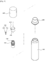
- FIG. 1 is an exploded perspective view illustrating a configuration of a pump container for discharging capsules according to an exemplary embodiment of the present invention.
- FIG. 2 is an assembled perspective view illustrating a configuration of a pump container for discharging capsules according to an exemplary embodiment of the present invention.
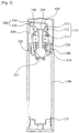
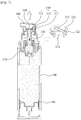
- FIG. 3 is a cross-sectional view illustrating a configuration of a pump container for discharging capsules according to an exemplary embodiment of the present invention.
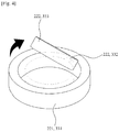
- FIG. 4 is an explanatory drawing illustrating a configuration of a first and a second valve member of a pump container for discharging capsules according to an exemplary embodiment of the present invention.
- a pump container for discharging capsules may include a tube body 100, a support body 200, a pumping member 300, and a button member 400.
- the tube body 100 storing liquid type contents or encapsulated granule contents (Hereafter called as "contents") is composed of a piston 110 at an inner lower portion which ascends according to the use of contents.
- a piston 110 is installed to the container body 100; however, it is possible various types of container like a tube container 100 can be configured, and also possible that a pouch receiving contents can be coupled at an inner side of the container body 100.
- the support body 200 coupled to an upper portion of the container body 100 and supporting a pumping member 300, comprises a cylinder 210 at a center portion thereof such that the pumping member 300 can be coupled and perform a pumping operation, wherein a content inflow hole 211 is installed at a lower portion of the cylinder 210 such that the contents stored in the container body 100 can flow in, and at an upper portion of the content inflow hole 211 is installed a first valve member 220 which opens/closes the content inflow hole 211 according to the change of inner pressure of the cylinder 210.
- the first valve member 220 is configured to get one side thereof to rotate up and down with the other side fixed and thereby to open/close the content inflow hole 211.
- a cylinder 210 comprises a first valve body 221 which is coupled with a combined fit, encasing an inner peripheral surface of the cylinder 210 at an inner lower portion of the cylinder 210, and forms a hollow, and a first opening/closing plate 223 which is coupled to one side to be able to rotate up and down through a first rotary support bar 222 and opens/closes the content inflow hole 211 according to the upward/downward rotation.
- the first valve member 223 is different from a conventional check valve in that a first opening/closing plate 223 rotates to upward direction and opens the content inflow hole 211 when the contents stored in the container body 100 flow in through the content inflow hole 223. Due to this, it is possible that encapsulated granule contents can flow into the inside of the cylinder 210 without being ruptured.
- an over cap 600 is coupled at the support body 200 for preventing a malfunction of a button member 400.
- the pumping member 300 is coupled to the cylinder 210 of the support body 200 and performs a pumping operation so as to discharge the contents stored in the container body 100, further including a stem 310, a seal cap 320, and a second valve member 330.
- the stem 310 has a button member 400 coupled at an upper portion thereof and a seal cap 320 coupled at a lower portion thereof, thereby moving according to the pressurization of the button member 400 and then allowing the ascent/descent of the seal cap 320.
- the seal cap 320 further comprises a content moving tube 311 which forms a passage where the contents flowing to the cylinder 210 can move to an upper portion, a coupling part 312 which extends to an upper portion of the content moving tube 311 and is coupled to an inner side of the button member 400, and a valve securing part 313 which is formed at an inner side of the coupling part 312 such that a second valve member 330, opening/closing an upper end of the content moving tube 311, can be secured In the present invention.
- the diameter of the content moving tube 311 is preferably bigger than the size of capsules.
- the seal cap 320 is coupled encasing a lower portion of the content moving tube 311, is contacted to an inner wall of the cylinder, and thereby changes an inner pressure of the cylinder 210.
- the seal cap 320 descends according to the movement of the stem 310 and leads the contents flowing into the inside of the cylinder 210 to move to a content discharging hole 410 through the content moving tube 311.
- the seal cap 320 ascends according to the movement of the stem 310 and allows the contents stored in the content body 100 to flow into the inside of the cylinder 210.
- the second valve member 330 is secured to a valve securing part 313 formed at an inner side of the coupling part 312, and opens/closes an upper end of the content moving tube 311 according to the change of the inner pressure of the cylinder 210.
- the second valve member 330 is configured to get one side to rotate up and down with the other side fixed and to open/close an upper end of the content moving tube 311.
- the second valve member 330 comprises a second valve body 331 which encases an inner peripheral surface of the coupling part 312, is coupled with a combined fit to the valve securing part 313, and forms a hollow, and a second opening/closing plate 333 which is coupled so as to be rotated up and down through a second rotary support bar 332 at one side of the inner peripheral surface of the second valve body 331 and opens/closes an upper end of the content moving tube 311 according to the upward/downward rotation thereof.
- the second valve member 330 unlike conventional ordinary check valves, makes a second opening/closing plate 333 rotate in an upper direction and open an upper end of the content moving tube 311 when the contents flowing into the cylinder 210 move to an upper portion thereof through the content moving tube 311. Due to this, the encapsulated granule contents can be discharged without being ruptured through the content discharging hole 410 to the outside.
- the pumping member 300 among the ordinary structures of a stem, a piston rod coupled to a lower portion of the stem, and a seal cap coupled encasing an outer peripheral surface of the piston rod at a lower portion of the piston rod and moving along an inner wall of the cylinder, excludes a piston rod and instead and includes a pump structure such that the seal cap can be coupled to an outer peripheral surface of the stem. Therefore, it is possible to save the expense by reducing the number of parts and also possible to discharge the encapsulated granule contents without capsules being ruptured because the contents can move directly to the content moving tube of the stem, not move through a content inflow outlet formed at an inner side of the piston rod.
- the button member 400 which is coupled to an upper portion of the pumping member 300 and delivers pressure according to user's pressurization to the pumping member 300, and thereby induces a pumping operation of the pumping member 300, comprises a content discharging hole 410 at a side thereof such that contents can be discharged by the pumping operation of the pumping member 300.
- a sealing member 500 which can be attached/detached to the content discharging hole 410 according to the use of contents, is coupled at the button member 400.
- the sealing member 500 comprises an insertion part 510 which opens/closes the content discharging hole 410 according to the insertion to or withdrawal from the content discharging hole 410, and a handle part 520 which extends from the insertion part 510 and can be gripped by a user.
- the sealing member 500 blocks leakage of contents or prevents air or other foreign matters from flowing into the content discharging hole 410, and allows the discharge of contents when detached from the content discharging hole 410.
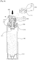
- FIGS. 5 to 7 are explanatory drawings illustrating a discharging process of contents in a pump container for discharging capsules according to an exemplary embodiment of the present invention.
- a pump container for discharging capsules when a user wants to discharge and use contents at a state that a cylinder 210 holds contents which has flowed into the inside thereof, a pump container for discharging capsules according to an exemplary embodiment of the present invention firstly detaches the sealing member 500 closing the content discharging hole 410 from the content discharging hole 410 and then pressurizes the button member 400.
- a second opening/closing plate 333 of a second valve member 330 rotate and opens an upper end of the content moving tube 311. Due to this, encapsulated granule contents can be discharged without being ruptured to the outside through the content discharging hole 410.
- the button member 400 ascends by an elastic force of a spring composed of the pumping member 300. Due to this, a first valve member 220 open a content inflow hole 211 by the pressure arising inside the cylinder 210, and thereby the contents stored in the container body 100 are discharged to the inside of the cylinder 210 through the content inflow hole 211.
- a first opening/closing plate 333 of the first valve member 220 rotates to an upward direction and opens the content inflow hole 211. Due to this, it is possible that encapsulated granule contents be moved to the inside of the cylinder 210 without encapsulated granule contents being ruptured.
- the present invention unlike conventional check valves, has a structure where the first opening/closing plate 223 and the second opening/closing plate 333 rotate to an upward direction and opens upper ends of the content inflow hole 211 and the content moving tube 311. Therefore, it is possible that a user can discharge contents without rupturing encapsulated granules and then ruptures the discharged capsules to mix with encapsulated granule contents for applying, thereby leading to increase the reliability of the product.
Landscapes
- Engineering & Computer Science (AREA)
- Mechanical Engineering (AREA)
- General Engineering & Computer Science (AREA)
- Containers And Packaging Bodies Having A Special Means To Remove Contents (AREA)
- Closures For Containers (AREA)
- Reciprocating Pumps (AREA)
Abstract
Description
- The present invention disclosed herein relates to a pump container for discharging capsules, in which an opening/closing plate of a valve member is coupled to the inner peripheral surface of a valve body through a rotary support to rotate up and down so as to open/close a content inflow hole and an upper end of a content movement tube, such that encapsulated granule contents can be discharged, without rupturing, during a pumping operation of a pumping member.
- Generally, among functional cosmetics, there are granule type cosmetics containing capsules where other ingredients are contained as a main component. In case of having to mix two incompatible ingredients such as vitamin A or vitamin C, or to add materials that tend to be spoiled easily if they are put together, these granule type cosmetics have specific ingredients which are put in capsules and mixed with basic ingredients of cosmetics.
- A container containing encapsulated granule contents as the above is disclosed in the registered utility model No. 20-0180852. (Hereafter called as the registered utility model)
- The registered utility model relates to a container, the container comprises a container body receiving encapsulated granule contents, a pump which is attached to an outlet part of the container body and thereby discharges the contents, a head having a nozzle, and a discharging passage connecting the outside through the pump and the head from the container body, wherein a net is installed to the passage for pulverize the encapsulated granule contents.
- The registered utility model is configured in a way that granule type cosmetics pass through and ruptured to be mixed with main ingredients and then discharged when the contents are discharged. However, a user cannot confirm whether the granule type cosmetics are ruptured and mixed during the discharging process of the contents or the granule type cosmetics are discharged after being mixed with main ingredients already ruptured. Hence, there arises a problem that the user cannot trust effectiveness of the product for fear that the contents thereof should be spoiled.
- Meanwhile, in case cosmetics are discharged according to a pumping operation through a pumping structure such as the registered utility model, it is possible that there arises a situation that a part of granular cosmetics is ruptured while passing through a check valve, e.g. a ball valve installed inside a cylinder of a pump. Due to this, cosmetic products may be degraded in terms of effectiveness.
- Accordingly, there increases a demand for a pumping structure which makes it possible to discharge granule type cosmetics with granules not being ruptured, such that a user can mix and use cosmetics while confirming the intactness of granule type cosmetics directly with her own eyes.
- The present invention is devised to solve said problems above, and its goal is to provide a pump container for discharging capsules, wherein an opening/closing plate of a valve member is coupled to the inner peripheral surface of a valve body through a rotary support to rotate up and down so as to open/close a content inflow hole and the upper end of a content movement tube, such that encapsulated granule contents can be discharged, without rupturing, during a pumping operation of a pumping member.
- To solve such problems described in the above, a pump container for discharging capsules according to the present invention comprises: a container body storing liquid type and encapsulated granule contents, and having a volume reduced according to the contents use; a support body coupled to an upper portion of the container body and supporting a pumping member, further comprising a cylinder where a content inflow hole is formed such that the contents stored in the container body can flow in; a pumping member coupled to the support body and performing a pumping operation such that the contents stored in the container body can be discharged to the outside, further including a content moving tube which forms a passage where the contents flowing into the cylinder can move to an upper portion thereof, a coupling part which extends to an upper portion of the content moving tube and is coupled to an inner side of a button member, a stem which consists of a valve securing part formed at an inner side of the coupling part such that a second valve member, which opens/closes an upper end of the content moving tube, can be secured, and a sealing cap which is coupled encasing an lower portion of the content moving tube and closely contacted to an inner wall of the cylinder, thereby changing an inner pressure of the cylinder according to the ascent/descent; and a button member which is coupled to an upper portion of the pumping member, delivering the pressure formed according to a user's pressurization to the pumping member, and thereby induces a pumping operation of the pumping member, further comprising a content discharging hole such that the contents can be discharged by a pumping operation of the pumping member.
- At the cylinder is installed a first valve member which is disposed at an upper portion of the content inflow hole and opens/closes the content inflow hole according to the change of inner pressure of the cylinder, and at the valve securing part is installed a second valve member which opens/closes an upper end of the content moving tube according to the change of inner pressure of the cylinder.
- The first valve member and the second valve member are configured to get one side to rotate up and down with the other side fixed so as to open/close an upper end of the content inflow hole and the content moving tube, wherein the diameter of the content moving tube is bigger than the size of encapsulated granule contents, such that the encapsulated granule contents can be discharged with capsules in the contents not being ruptured.
- Furthermore, the first valve member is configured to include a first valve body which is coupled with a combined fit, encasing an inner peripheral surface of the cylinder, and forms a hollow, and also a first opening/closing plate which is coupled at one side of an inner peripheral surface of the first valve body to be able to be rotated up and down by means of a first rotary support bar and thereby opens/closes the content inflow hole according to an upward/downward rotation.
- Furthermore, the second valve member includes a second valve body which is coupled with a combined fit, encasing an inner peripheral surface of the coupling part, and forms a hollow, and a second opening/closing plate which is coupled at one side of an inner peripheral surface of the second valve body to be able to be rotated up and down by means of a second rotary support bar, and thereby opens/closes the content inflow hole according to an upward/downward rotation.
- Furthermore, at the button member is coupled a sealing member capable of being attached/detached to the content discharging hole according to the use of contents, wherein the sealing member comprises an insertion part which opens/closes the content discharging hole according to the insertion to/withdrawal from the content discharging hole, and a handle part which extends from the insertion part and can gripped by a user.
- As described above, the present invention is provided with an opening/closing plate of a valve member which is coupled to the inner peripheral surface of a valve body through a rotary support bar to rotate up and down so as to open/close a content inflow hole and the upper end of a content movement tube, such that encapsulated granule contents can be discharged, without capsules being ruptured, during a pumping operation of a pumping member.
-
-
FIG. 1 is an exploded perspective view illustrating a configuration of a pump container for discharging capsules according to an exemplary embodiment of the present invention. -
FIG. 2 is an assembled perspective view illustrating a configuration of a pump container for discharging capsules according to an exemplary embodiment of the present invention. -
FIG. 3 is a cross-sectional view illustrating a configuration of a pump container for discharging capsules according to an exemplary embodiment of the present invention. -
FIG. 4 is an explanatory drawing illustrating a configuration of a first and a second valve member of a pump container for discharging capsules according to an exemplary embodiment of the present invention. -
FIGS. 5 to 7 are explanatory drawings illustrating a discharging process of a pump container for discharging capsules according to an exemplary embodiment of the present invention. - Hereinafter, exemplary embodiments of the present invention will be described in detail with reference to the accompanying drawings. The same reference numerals provided in the drawings indicate the same members.
-
FIG. 1 is an exploded perspective view illustrating a configuration of a pump container for discharging capsules according to an exemplary embodiment of the present invention.FIG. 2 is an assembled perspective view illustrating a configuration of a pump container for discharging capsules according to an exemplary embodiment of the present invention. -
FIG. 3 is a cross-sectional view illustrating a configuration of a pump container for discharging capsules according to an exemplary embodiment of the present invention.FIG. 4 is an explanatory drawing illustrating a configuration of a first and a second valve member of a pump container for discharging capsules according to an exemplary embodiment of the present invention. - Referring to
FIGS. 1 to 4 , a pump container for discharging capsules according to an exemplary embodiment of the present invention may include atube body 100, asupport body 200, apumping member 300, and abutton member 400. - The
tube body 100 storing liquid type contents or encapsulated granule contents (Hereafter called as "contents") is composed of apiston 110 at an inner lower portion which ascends according to the use of contents. In the drawings of the present invention, apiston 110 is installed to thecontainer body 100; however, it is possible various types of container like atube container 100 can be configured, and also possible that a pouch receiving contents can be coupled at an inner side of thecontainer body 100. - The
support body 200, coupled to an upper portion of thecontainer body 100 and supporting apumping member 300, comprises acylinder 210 at a center portion thereof such that thepumping member 300 can be coupled and perform a pumping operation, wherein acontent inflow hole 211 is installed at a lower portion of thecylinder 210 such that the contents stored in thecontainer body 100 can flow in, and at an upper portion of thecontent inflow hole 211 is installed afirst valve member 220 which opens/closes thecontent inflow hole 211 according to the change of inner pressure of thecylinder 210. - In the present invention, the
first valve member 220 is configured to get one side thereof to rotate up and down with the other side fixed and thereby to open/close thecontent inflow hole 211. To do this, acylinder 210 comprises afirst valve body 221 which is coupled with a combined fit, encasing an inner peripheral surface of thecylinder 210 at an inner lower portion of thecylinder 210, and forms a hollow, and a first opening/closing plate 223 which is coupled to one side to be able to rotate up and down through a firstrotary support bar 222 and opens/closes thecontent inflow hole 211 according to the upward/downward rotation. - The
first valve member 223 is different from a conventional check valve in that a first opening/closing plate 223 rotates to upward direction and opens thecontent inflow hole 211 when the contents stored in thecontainer body 100 flow in through thecontent inflow hole 223. Due to this, it is possible that encapsulated granule contents can flow into the inside of thecylinder 210 without being ruptured. - Meanwhile, an over
cap 600 is coupled at thesupport body 200 for preventing a malfunction of abutton member 400. - The
pumping member 300 is coupled to thecylinder 210 of thesupport body 200 and performs a pumping operation so as to discharge the contents stored in thecontainer body 100, further including astem 310, aseal cap 320, and asecond valve member 330. - The
stem 310 has abutton member 400 coupled at an upper portion thereof and aseal cap 320 coupled at a lower portion thereof, thereby moving according to the pressurization of thebutton member 400 and then allowing the ascent/descent of theseal cap 320. Theseal cap 320 further comprises acontent moving tube 311 which forms a passage where the contents flowing to thecylinder 210 can move to an upper portion, acoupling part 312 which extends to an upper portion of thecontent moving tube 311 and is coupled to an inner side of thebutton member 400, and avalve securing part 313 which is formed at an inner side of thecoupling part 312 such that asecond valve member 330, opening/closing an upper end of thecontent moving tube 311, can be secured In the present invention. - In order for the encapsulated granule contents not to be ruptured during the process of moving, the diameter of the
content moving tube 311 is preferably bigger than the size of capsules. - The
seal cap 320 is coupled encasing a lower portion of thecontent moving tube 311, is contacted to an inner wall of the cylinder, and thereby changes an inner pressure of thecylinder 210. When thebutton member 400 is pressed, theseal cap 320 descends according to the movement of thestem 310 and leads the contents flowing into the inside of thecylinder 210 to move to acontent discharging hole 410 through thecontent moving tube 311. Meanwhile, when thebutton member 400 is not pressed, theseal cap 320 ascends according to the movement of thestem 310 and allows the contents stored in thecontent body 100 to flow into the inside of thecylinder 210. - The
second valve member 330 is secured to avalve securing part 313 formed at an inner side of thecoupling part 312, and opens/closes an upper end of thecontent moving tube 311 according to the change of the inner pressure of thecylinder 210. In the present invention, thesecond valve member 330 is configured to get one side to rotate up and down with the other side fixed and to open/close an upper end of thecontent moving tube 311. To do this, thesecond valve member 330 comprises asecond valve body 331 which encases an inner peripheral surface of thecoupling part 312, is coupled with a combined fit to thevalve securing part 313, and forms a hollow, and a second opening/closing plate 333 which is coupled so as to be rotated up and down through a secondrotary support bar 332 at one side of the inner peripheral surface of thesecond valve body 331 and opens/closes an upper end of thecontent moving tube 311 according to the upward/downward rotation thereof. - The
second valve member 330, unlike conventional ordinary check valves, makes a second opening/closing plate 333 rotate in an upper direction and open an upper end of thecontent moving tube 311 when the contents flowing into thecylinder 210 move to an upper portion thereof through thecontent moving tube 311. Due to this, the encapsulated granule contents can be discharged without being ruptured through thecontent discharging hole 410 to the outside. - Meanwhile, the pumping
member 300, among the ordinary structures of a stem, a piston rod coupled to a lower portion of the stem, and a seal cap coupled encasing an outer peripheral surface of the piston rod at a lower portion of the piston rod and moving along an inner wall of the cylinder, excludes a piston rod and instead and includes a pump structure such that the seal cap can be coupled to an outer peripheral surface of the stem. Therefore, it is possible to save the expense by reducing the number of parts and also possible to discharge the encapsulated granule contents without capsules being ruptured because the contents can move directly to the content moving tube of the stem, not move through a content inflow outlet formed at an inner side of the piston rod. - The
button member 400, which is coupled to an upper portion of thepumping member 300 and delivers pressure according to user's pressurization to thepumping member 300, and thereby induces a pumping operation of thepumping member 300, comprises acontent discharging hole 410 at a side thereof such that contents can be discharged by the pumping operation of thepumping member 300. - In the present invention, a
sealing member 500, which can be attached/detached to thecontent discharging hole 410 according to the use of contents, is coupled at thebutton member 400. The sealingmember 500 comprises aninsertion part 510 which opens/closes thecontent discharging hole 410 according to the insertion to or withdrawal from thecontent discharging hole 410, and ahandle part 520 which extends from theinsertion part 510 and can be gripped by a user. - The sealing
member 500 blocks leakage of contents or prevents air or other foreign matters from flowing into thecontent discharging hole 410, and allows the discharge of contents when detached from thecontent discharging hole 410. - Hereinafter, referring
FIGS. 5 to 7 , an operational state of a pump container for discharging capsules according to an exemplary embodiment of the present invention will be described.FIGS. 5 to 7 are explanatory drawings illustrating a discharging process of contents in a pump container for discharging capsules according to an exemplary embodiment of the present invention. - Referring
FIGS. 5 to 7 , when a user wants to discharge and use contents at a state that acylinder 210 holds contents which has flowed into the inside thereof, a pump container for discharging capsules according to an exemplary embodiment of the present invention firstly detaches the sealingmember 500 closing thecontent discharging hole 410 from thecontent discharging hole 410 and then pressurizes thebutton member 400. - As the above when the
button member 400 is pressurized, the pumping operation of the pumpingmember 300 disposed at a lower portion thereof. Due to this, contents ascends through thecontent moving tube 311 by the pressure arising inside thecylinder 210, and then thesecond valve member 330 opens an upper end of thecontent moving tube 311 by the pressure caused by the ascending contents and discharge the contents through thecontent discharging hole 410. - At this moment, a second opening/
closing plate 333 of asecond valve member 330 rotate and opens an upper end of thecontent moving tube 311. Due to this, encapsulated granule contents can be discharged without being ruptured to the outside through thecontent discharging hole 410. - Next, if the
button member 400 is released from pressurization, thebutton member 400 ascends by an elastic force of a spring composed of the pumpingmember 300. Due to this, afirst valve member 220 open acontent inflow hole 211 by the pressure arising inside thecylinder 210, and thereby the contents stored in thecontainer body 100 are discharged to the inside of thecylinder 210 through thecontent inflow hole 211. - At this moment, a first opening/
closing plate 333 of thefirst valve member 220 rotates to an upward direction and opens thecontent inflow hole 211. Due to this, it is possible that encapsulated granule contents be moved to the inside of thecylinder 210 without encapsulated granule contents being ruptured. - As previously described, the present invention, unlike conventional check valves, has a structure where the first opening/
closing plate 223 and the second opening/closing plate 333 rotate to an upward direction and opens upper ends of thecontent inflow hole 211 and thecontent moving tube 311. Therefore, it is possible that a user can discharge contents without rupturing encapsulated granules and then ruptures the discharged capsules to mix with encapsulated granule contents for applying, thereby leading to increase the reliability of the product. - As described above, optimal embodiments have been disclosed in the drawings and the specification. Although specific terms have been used herein, these are only intended to describe the present invention and are not intended to limit the meanings of the terms or to restrict the scope of the present invention as disclosed in the accompanying claims. Therefore, those skilled in the art will appreciate that various modifications and other equivalent embodiments are possible from the above embodiments. Therefore, the scope of the present invention should be defined by the technical spirit of the accompanying claims.
Claims (4)
- A pump container for discharging capsules comprising:a container body (100) storing liquid type and encapsulated granule contents, and having a volume reduced according to the use of contents;a support body (200) coupled to an upper portion of the container body (100) and supporting a pumping member (300), further comprising a cylinder (210) where a content inflow hole (211) is formed such that the contents stored in the container body (100) can flow in;a pumping member (300) coupled to the support body (200) and performing a pumping operation such that the contents stored in the container body (100) can be discharged to the outside, further including a content moving tube (311) forming a passage where the contents flowing into the cylinder (210) can move to an upper portion thereof, a coupling part (312) extending to an upper portion of the content moving tube (311) and coupled to an inner side of a button member (400), a stem (310) consisting of a valve securing part (313) formed at an inner side of the coupling part (312) such that a second valve member (330) opening/closing an upper end of the content moving tube (311) can be secured, and a sealing cap (500) which is coupled encasing an lower portion of the content moving tube (311) and is closely contacted to an inner wall of the cylinder (210), thereby changing an inner pressure of the cylinder (210) according to the ascent/descent; anda button member (400) coupled to an upper portion of the pumping member (300), delivering the pressure formed according to a user's pressurization to the pumping member (300), and thereby inducing a pumping operation of the pumping member (300), further comprising a content discharging hole (410) such that the contents can be discharged by a pumping operation of the pumping member (300),wherein at the cylinder (210) is installed a first valve member (220) disposed at an upper portion of the content inflow hole (211) and opening/closing the content inflow hole (211) according to the change of inner pressure of the cylinder (210), and at the valve securing part (313) is installed a second valve member (331) which opens/closes an upper end of the content moving tube (311) according to the change of inner pressure of the cylinder (210),wherein the first valve member (220) and the second valve member (330) are configured to get one side to rotate up and down with the other side fixed so as to open/close an upper end of the content inflow hole (211) and the content moving tube (311), wherein the diameter of the content moving tube (311) is bigger than the size of encapsulated granule contents, such that the encapsulated granule contents can be discharged with capsules in the contents not being ruptured.
- The pump container for discharging capsules of claim 1,
wherein the first valve member (220) includes a first valve body (221) coupled with a combined fit, encasing an inner peripheral surface of the cylinder (210), and forming a hollow, and a first opening/closing plate (223) coupled at one side of an inner peripheral surface of the first valve body (221) to be able to be rotated up and down by means of a first rotary support bar (222) and thereby opening/closing the content inflow hole (211) according to an upward/downward rotation. - The pump container for discharging capsules of claim 1,
wherein the second valve member includes a second valve body (330) coupled with a combined fit, encasing an inner peripheral surface of the coupling part (312) and forming a hollow, and a second opening/closing plate (333) coupled at one side of an inner peripheral surface of the second valve body (331) to be able to be rotated up and down by means of a second rotary support bar (332), and thereby opening/closing the content inflow hole (211) according to an upward/downward rotation. - The pump container for discharging capsules of claim 1,
wherein at the button member (400) is coupled a sealing member (500) capable of being attached/detached to the content discharging hole (410) according to the use of contents, wherein the sealing member (500) comprises an insertion part (510) opening/closing the content discharging hole (410) according to the insertion to/withdrawal from the content discharging hole (410), and a handle part (520) extending from the insertion part (510) and gripped by a user.
Applications Claiming Priority (2)
| Application Number | Priority Date | Filing Date | Title |
|---|---|---|---|
| KR20140072730A KR101501027B1 (en) | 2014-06-16 | 2014-06-16 | Pump vessel for dispensing of capsule |
| PCT/KR2015/004943 WO2015194761A1 (en) | 2014-06-16 | 2015-05-18 | Pump container for discharging capsules |
Publications (3)
| Publication Number | Publication Date |
|---|---|
| EP3156348A1 true EP3156348A1 (en) | 2017-04-19 |
| EP3156348A4 EP3156348A4 (en) | 2018-02-21 |
| EP3156348B1 EP3156348B1 (en) | 2019-02-13 |
Family
ID=53027061
Family Applications (1)
| Application Number | Title | Priority Date | Filing Date |
|---|---|---|---|
| EP15808916.9A Active EP3156348B1 (en) | 2014-06-16 | 2015-05-18 | Pump container for discharging capsules |
Country Status (7)
| Country | Link |
|---|---|
| US (1) | US20170136478A1 (en) |
| EP (1) | EP3156348B1 (en) |
| JP (1) | JP6663362B2 (en) |
| KR (1) | KR101501027B1 (en) |
| CN (1) | CN106458393B (en) |
| ES (1) | ES2718537T3 (en) |
| WO (1) | WO2015194761A1 (en) |
Families Citing this family (9)
| Publication number | Priority date | Publication date | Assignee | Title |
|---|---|---|---|---|
| EP3484628B1 (en) * | 2016-07-18 | 2020-08-26 | RPC Bramlage GmbH | Dispenser of liquid or pasty products |
| CN108245774A (en) * | 2016-12-29 | 2018-07-06 | 株式会社基纳希施 | It is equipped with the cosmetics containers of micropin idler wheel |
| KR101906979B1 (en) * | 2017-03-09 | 2018-10-11 | (주)연우 | Pump vessel for dispensing of bead |
| EP3810313A4 (en) * | 2018-06-21 | 2022-04-13 | Silgan Dispensing Systems Corporation | DISTRIBUTION SET INCLUDING ADDITIVE MIXING DEVICE |
| KR102171859B1 (en) * | 2019-01-07 | 2020-10-29 | (주)연우 | A button retractable type container for cometics |
| KR102174778B1 (en) * | 2019-04-03 | 2020-11-05 | 카페24 주식회사 | Cosmetic container |
| CN111942753B (en) * | 2020-09-10 | 2022-06-21 | 深圳市赛尔美电子科技有限公司 | Atomized liquid storage device |
| FR3156350A1 (en) * | 2023-12-12 | 2025-06-13 | Capsum | Device suitable for packaging a heterogeneous mixture and distributing it in the form of a spray of fluid composition |
| KR102887018B1 (en) * | 2024-02-02 | 2025-11-14 | 강성일 | Content exhaust pump container |
Family Cites Families (25)
| Publication number | Priority date | Publication date | Assignee | Title |
|---|---|---|---|---|
| US3507586A (en) * | 1968-04-04 | 1970-04-21 | Erich W Gronemeyer | Pump |
| DE3601311A1 (en) * | 1986-01-17 | 1987-07-23 | Joachim Czech | DISPENSER FOR PASTOESE PRODUCTS |
| US4685594A (en) * | 1986-07-03 | 1987-08-11 | Manuel Czech | Dispenser for paste-like products |
| JPH0615195Y2 (en) * | 1987-08-18 | 1994-04-20 | 株式会社吉野工業所 | Check valve structure |
| JPH064946Y2 (en) * | 1987-10-29 | 1994-02-09 | ぺんてる株式会社 | Applicator |
| US4872596A (en) * | 1988-03-15 | 1989-10-10 | Calmar Inc. | Viscous product dispenser |
| FR2650255B1 (en) * | 1989-07-25 | 1992-01-10 | Oreal | DISPENSING ASSEMBLY OF ONE OR MORE PRODUCT (S) IN THE FORM OF A CREAM, LIQUID OR POWDER, ESPECIALLY COSMETIC PRODUCTS |
| JPH1017045A (en) * | 1996-07-04 | 1998-01-20 | Kao Corp | Check valve |
| JPH1059405A (en) * | 1996-08-19 | 1998-03-03 | Kao Corp | Liquid discharge pump |
| JP3720542B2 (en) * | 1997-07-25 | 2005-11-30 | 株式会社吉野工業所 | Liquid ejector |
| AU718713B2 (en) * | 1997-09-09 | 2000-04-20 | Johnson & Johnson Consumer Companies, Inc. | Closure |
| DE29717034U1 (en) * | 1997-09-23 | 1999-01-28 | Josef Wischerath Gmbh & Co. Kg, 50259 Pulheim | Dispenser pump, dispenser and modular dispenser system |
| US6612468B2 (en) * | 2000-09-15 | 2003-09-02 | Rieke Corporation | Dispenser pumps |
| JP4798899B2 (en) * | 2001-08-29 | 2011-10-19 | 株式会社 資生堂 | Capsule-containing external composition |
| US6640999B2 (en) * | 2001-11-13 | 2003-11-04 | Unilever Home & Personal Care Usa, Division Of Conopco, Inc. | Dose dispensing pump for dispensing two or more materials |
| DE20201742U1 (en) * | 2002-02-05 | 2003-03-20 | RPC Wiko GmbH & Co. KG, 50259 Pulheim | Dispenser for flowable products |
| DE20203473U1 (en) * | 2002-03-05 | 2003-04-17 | RPC Wiko GmbH & Co. KG, 50259 Pulheim | Dispenser for flowable products with spherically encapsulated components |
| CN2579835Y (en) * | 2002-09-04 | 2003-10-15 | 张家港市环亚喷雾塑业有限公司 | Liquid distribution quantity pump |
| US7367476B2 (en) * | 2004-08-30 | 2008-05-06 | Rieke Corporation | Airless dispensing pump with tamper evidence features |
| US7654418B2 (en) * | 2004-08-30 | 2010-02-02 | Rieke Corporation | Airless dispensing pump |
| US7870977B2 (en) * | 2005-04-28 | 2011-01-18 | Meadwestvaco Calmar, Inc. | Dispenser having an improved inlet valve |
| JP5182785B2 (en) * | 2007-03-30 | 2013-04-17 | 株式会社吉野工業所 | Pump container |
| KR101378369B1 (en) * | 2011-06-14 | 2014-03-27 | (주)연우 | Pumping type cosmetic vessel |
| KR101261813B1 (en) * | 2011-07-27 | 2013-05-14 | (주)민진 | fluorine valve having pump type comestic receptacle |
| US9596917B2 (en) * | 2013-11-22 | 2017-03-21 | Toly Korea Inc. | Cosmetic container with pulverizing apparatus for granulated cosmetic |
-
2014
- 2014-06-16 KR KR20140072730A patent/KR101501027B1/en active Active
-
2015
- 2015-05-18 WO PCT/KR2015/004943 patent/WO2015194761A1/en not_active Ceased
- 2015-05-18 EP EP15808916.9A patent/EP3156348B1/en active Active
- 2015-05-18 JP JP2016573113A patent/JP6663362B2/en active Active
- 2015-05-18 US US15/318,944 patent/US20170136478A1/en not_active Abandoned
- 2015-05-18 ES ES15808916T patent/ES2718537T3/en active Active
- 2015-05-18 CN CN201580032635.2A patent/CN106458393B/en active Active
Also Published As
| Publication number | Publication date |
|---|---|
| US20170136478A1 (en) | 2017-05-18 |
| ES2718537T3 (en) | 2019-07-02 |
| EP3156348B1 (en) | 2019-02-13 |
| CN106458393A (en) | 2017-02-22 |
| JP6663362B2 (en) | 2020-03-11 |
| CN106458393B (en) | 2018-08-17 |
| KR101501027B1 (en) | 2015-03-12 |
| EP3156348A4 (en) | 2018-02-21 |
| WO2015194761A1 (en) | 2015-12-23 |
| JP2017521329A (en) | 2017-08-03 |
Similar Documents
| Publication | Publication Date | Title |
|---|---|---|
| US20170136478A1 (en) | Pump container for discharging capsules | |
| US11006725B2 (en) | Bead discharge pump container | |
| KR101430988B1 (en) | Cosmetic vessel having mixed two-type materials | |
| JP2014522289A (en) | Pumping cosmetic container | |
| JP7032562B2 (en) | Fixed-quantity discharge device for liquid containers | |
| US20180079584A1 (en) | Mixing container for heterogeneous content | |
| JP2018510821A (en) | Dissimilar contents mixing container | |
| CN109415145A (en) | Container-closure with the mechanism introduced the additive into the liquid in container | |
| RU2294874C2 (en) | Dispensing device for fluid-flow products with ball-shaped encapsulated components | |
| KR102272109B1 (en) | Pump dispenser for shampoo vessel | |
| JP2017508675A (en) | Foam spout tube container | |
| JP2018532659A (en) | Foam spout tube container | |
| EP2835322A1 (en) | Tube vessel capable of preventing air infiltration | |
| US9527658B2 (en) | Metering valve fillable through the valve | |
| KR101383919B1 (en) | Cosmetics container of different kind of fluid | |
| KR101472788B1 (en) | Pump vessel for dispensing of capsule | |
| ES2848202T3 (en) | Dispensing valve incorporating a dosing valve | |
| KR101574718B1 (en) | The multi-directiona sprayer | |
| KR101676027B1 (en) | Cosmetic vessel having mixed two-type materials | |
| CN105129250B (en) | A kind of universal quantitative valve of monomer and aerosol can | |
| JPH0318321Y2 (en) | ||
| KR102285081B1 (en) | The increasing device of discharging force of cosmetic vessel | |
| RU2257321C1 (en) | Vessel for multicomponent products | |
| JPH0439178Y2 (en) | ||
| CN110171633B (en) | Metering bottle |
Legal Events
| Date | Code | Title | Description |
|---|---|---|---|
| STAA | Information on the status of an ep patent application or granted ep patent |
Free format text: STATUS: THE INTERNATIONAL PUBLICATION HAS BEEN MADE |
|
| PUAI | Public reference made under article 153(3) epc to a published international application that has entered the european phase |
Free format text: ORIGINAL CODE: 0009012 |
|
| STAA | Information on the status of an ep patent application or granted ep patent |
Free format text: STATUS: REQUEST FOR EXAMINATION WAS MADE |
|
| 17P | Request for examination filed |
Effective date: 20170116 |
|
| AK | Designated contracting states |
Kind code of ref document: A1 Designated state(s): AL AT BE BG CH CY CZ DE DK EE ES FI FR GB GR HR HU IE IS IT LI LT LU LV MC MK MT NL NO PL PT RO RS SE SI SK SM TR |
|
| AX | Request for extension of the european patent |
Extension state: BA ME |
|
| DAV | Request for validation of the european patent (deleted) | ||
| DAX | Request for extension of the european patent (deleted) | ||
| A4 | Supplementary search report drawn up and despatched |
Effective date: 20180122 |
|
| RIC1 | Information provided on ipc code assigned before grant |
Ipc: B05B 11/00 20060101AFI20180116BHEP |
|
| REG | Reference to a national code |
Ref country code: DE Ref legal event code: R079 Ref document number: 602015024662 Country of ref document: DE Free format text: PREVIOUS MAIN CLASS: B65D0047340000 Ipc: B05B0011000000 |
|
| GRAP | Despatch of communication of intention to grant a patent |
Free format text: ORIGINAL CODE: EPIDOSNIGR1 |
|
| STAA | Information on the status of an ep patent application or granted ep patent |
Free format text: STATUS: GRANT OF PATENT IS INTENDED |
|
| RIC1 | Information provided on ipc code assigned before grant |
Ipc: B05B 11/00 20060101AFI20180831BHEP |
|
| INTG | Intention to grant announced |
Effective date: 20180925 |
|
| GRAS | Grant fee paid |
Free format text: ORIGINAL CODE: EPIDOSNIGR3 |
|
| GRAA | (expected) grant |
Free format text: ORIGINAL CODE: 0009210 |
|
| STAA | Information on the status of an ep patent application or granted ep patent |
Free format text: STATUS: THE PATENT HAS BEEN GRANTED |
|
| AK | Designated contracting states |
Kind code of ref document: B1 Designated state(s): AL AT BE BG CH CY CZ DE DK EE ES FI FR GB GR HR HU IE IS IT LI LT LU LV MC MK MT NL NO PL PT RO RS SE SI SK SM TR |
|
| REG | Reference to a national code |
Ref country code: GB Ref legal event code: FG4D |
|
| REG | Reference to a national code |
Ref country code: CH Ref legal event code: EP Ref country code: AT Ref legal event code: REF Ref document number: 1095895 Country of ref document: AT Kind code of ref document: T Effective date: 20190215 |
|
| REG | Reference to a national code |
Ref country code: IE Ref legal event code: FG4D |
|
| REG | Reference to a national code |
Ref country code: DE Ref legal event code: R096 Ref document number: 602015024662 Country of ref document: DE |
|
| REG | Reference to a national code |
Ref country code: LT Ref legal event code: MG4D |
|
| REG | Reference to a national code |
Ref country code: NL Ref legal event code: MP Effective date: 20190213 |
|
| REG | Reference to a national code |
Ref country code: ES Ref legal event code: FG2A Ref document number: 2718537 Country of ref document: ES Kind code of ref document: T3 Effective date: 20190702 |
|
| PG25 | Lapsed in a contracting state [announced via postgrant information from national office to epo] |
Ref country code: NL Free format text: LAPSE BECAUSE OF FAILURE TO SUBMIT A TRANSLATION OF THE DESCRIPTION OR TO PAY THE FEE WITHIN THE PRESCRIBED TIME-LIMIT Effective date: 20190213 Ref country code: LT Free format text: LAPSE BECAUSE OF FAILURE TO SUBMIT A TRANSLATION OF THE DESCRIPTION OR TO PAY THE FEE WITHIN THE PRESCRIBED TIME-LIMIT Effective date: 20190213 Ref country code: FI Free format text: LAPSE BECAUSE OF FAILURE TO SUBMIT A TRANSLATION OF THE DESCRIPTION OR TO PAY THE FEE WITHIN THE PRESCRIBED TIME-LIMIT Effective date: 20190213 Ref country code: SE Free format text: LAPSE BECAUSE OF FAILURE TO SUBMIT A TRANSLATION OF THE DESCRIPTION OR TO PAY THE FEE WITHIN THE PRESCRIBED TIME-LIMIT Effective date: 20190213 Ref country code: PT Free format text: LAPSE BECAUSE OF FAILURE TO SUBMIT A TRANSLATION OF THE DESCRIPTION OR TO PAY THE FEE WITHIN THE PRESCRIBED TIME-LIMIT Effective date: 20190613 Ref country code: NO Free format text: LAPSE BECAUSE OF FAILURE TO SUBMIT A TRANSLATION OF THE DESCRIPTION OR TO PAY THE FEE WITHIN THE PRESCRIBED TIME-LIMIT Effective date: 20190513 |
|
| PG25 | Lapsed in a contracting state [announced via postgrant information from national office to epo] |
Ref country code: BG Free format text: LAPSE BECAUSE OF FAILURE TO SUBMIT A TRANSLATION OF THE DESCRIPTION OR TO PAY THE FEE WITHIN THE PRESCRIBED TIME-LIMIT Effective date: 20190513 Ref country code: GR Free format text: LAPSE BECAUSE OF FAILURE TO SUBMIT A TRANSLATION OF THE DESCRIPTION OR TO PAY THE FEE WITHIN THE PRESCRIBED TIME-LIMIT Effective date: 20190514 Ref country code: IS Free format text: LAPSE BECAUSE OF FAILURE TO SUBMIT A TRANSLATION OF THE DESCRIPTION OR TO PAY THE FEE WITHIN THE PRESCRIBED TIME-LIMIT Effective date: 20190613 Ref country code: LV Free format text: LAPSE BECAUSE OF FAILURE TO SUBMIT A TRANSLATION OF THE DESCRIPTION OR TO PAY THE FEE WITHIN THE PRESCRIBED TIME-LIMIT Effective date: 20190213 Ref country code: HR Free format text: LAPSE BECAUSE OF FAILURE TO SUBMIT A TRANSLATION OF THE DESCRIPTION OR TO PAY THE FEE WITHIN THE PRESCRIBED TIME-LIMIT Effective date: 20190213 Ref country code: RS Free format text: LAPSE BECAUSE OF FAILURE TO SUBMIT A TRANSLATION OF THE DESCRIPTION OR TO PAY THE FEE WITHIN THE PRESCRIBED TIME-LIMIT Effective date: 20190213 |
|
| REG | Reference to a national code |
Ref country code: AT Ref legal event code: MK05 Ref document number: 1095895 Country of ref document: AT Kind code of ref document: T Effective date: 20190213 |
|
| PG25 | Lapsed in a contracting state [announced via postgrant information from national office to epo] |
Ref country code: AL Free format text: LAPSE BECAUSE OF FAILURE TO SUBMIT A TRANSLATION OF THE DESCRIPTION OR TO PAY THE FEE WITHIN THE PRESCRIBED TIME-LIMIT Effective date: 20190213 Ref country code: RO Free format text: LAPSE BECAUSE OF FAILURE TO SUBMIT A TRANSLATION OF THE DESCRIPTION OR TO PAY THE FEE WITHIN THE PRESCRIBED TIME-LIMIT Effective date: 20190213 Ref country code: CZ Free format text: LAPSE BECAUSE OF FAILURE TO SUBMIT A TRANSLATION OF THE DESCRIPTION OR TO PAY THE FEE WITHIN THE PRESCRIBED TIME-LIMIT Effective date: 20190213 Ref country code: EE Free format text: LAPSE BECAUSE OF FAILURE TO SUBMIT A TRANSLATION OF THE DESCRIPTION OR TO PAY THE FEE WITHIN THE PRESCRIBED TIME-LIMIT Effective date: 20190213 Ref country code: SK Free format text: LAPSE BECAUSE OF FAILURE TO SUBMIT A TRANSLATION OF THE DESCRIPTION OR TO PAY THE FEE WITHIN THE PRESCRIBED TIME-LIMIT Effective date: 20190213 Ref country code: IT Free format text: LAPSE BECAUSE OF FAILURE TO SUBMIT A TRANSLATION OF THE DESCRIPTION OR TO PAY THE FEE WITHIN THE PRESCRIBED TIME-LIMIT Effective date: 20190213 Ref country code: DK Free format text: LAPSE BECAUSE OF FAILURE TO SUBMIT A TRANSLATION OF THE DESCRIPTION OR TO PAY THE FEE WITHIN THE PRESCRIBED TIME-LIMIT Effective date: 20190213 |
|
| REG | Reference to a national code |
Ref country code: DE Ref legal event code: R097 Ref document number: 602015024662 Country of ref document: DE |
|
| PG25 | Lapsed in a contracting state [announced via postgrant information from national office to epo] |
Ref country code: PL Free format text: LAPSE BECAUSE OF FAILURE TO SUBMIT A TRANSLATION OF THE DESCRIPTION OR TO PAY THE FEE WITHIN THE PRESCRIBED TIME-LIMIT Effective date: 20190213 Ref country code: SM Free format text: LAPSE BECAUSE OF FAILURE TO SUBMIT A TRANSLATION OF THE DESCRIPTION OR TO PAY THE FEE WITHIN THE PRESCRIBED TIME-LIMIT Effective date: 20190213 |
|
| PLBE | No opposition filed within time limit |
Free format text: ORIGINAL CODE: 0009261 |
|
| STAA | Information on the status of an ep patent application or granted ep patent |
Free format text: STATUS: NO OPPOSITION FILED WITHIN TIME LIMIT |
|
| REG | Reference to a national code |
Ref country code: CH Ref legal event code: PL |
|
| PG25 | Lapsed in a contracting state [announced via postgrant information from national office to epo] |
Ref country code: AT Free format text: LAPSE BECAUSE OF FAILURE TO SUBMIT A TRANSLATION OF THE DESCRIPTION OR TO PAY THE FEE WITHIN THE PRESCRIBED TIME-LIMIT Effective date: 20190213 |
|
| 26N | No opposition filed |
Effective date: 20191114 |
|
| PG25 | Lapsed in a contracting state [announced via postgrant information from national office to epo] |
Ref country code: CH Free format text: LAPSE BECAUSE OF NON-PAYMENT OF DUE FEES Effective date: 20190531 Ref country code: MC Free format text: LAPSE BECAUSE OF FAILURE TO SUBMIT A TRANSLATION OF THE DESCRIPTION OR TO PAY THE FEE WITHIN THE PRESCRIBED TIME-LIMIT Effective date: 20190213 Ref country code: LI Free format text: LAPSE BECAUSE OF NON-PAYMENT OF DUE FEES Effective date: 20190531 |
|
| REG | Reference to a national code |
Ref country code: BE Ref legal event code: MM Effective date: 20190531 |
|
| PG25 | Lapsed in a contracting state [announced via postgrant information from national office to epo] |
Ref country code: SI Free format text: LAPSE BECAUSE OF FAILURE TO SUBMIT A TRANSLATION OF THE DESCRIPTION OR TO PAY THE FEE WITHIN THE PRESCRIBED TIME-LIMIT Effective date: 20190213 Ref country code: LU Free format text: LAPSE BECAUSE OF NON-PAYMENT OF DUE FEES Effective date: 20190518 |
|
| PG25 | Lapsed in a contracting state [announced via postgrant information from national office to epo] |
Ref country code: TR Free format text: LAPSE BECAUSE OF FAILURE TO SUBMIT A TRANSLATION OF THE DESCRIPTION OR TO PAY THE FEE WITHIN THE PRESCRIBED TIME-LIMIT Effective date: 20190213 |
|
| PG25 | Lapsed in a contracting state [announced via postgrant information from national office to epo] |
Ref country code: IE Free format text: LAPSE BECAUSE OF NON-PAYMENT OF DUE FEES Effective date: 20190518 |
|
| PG25 | Lapsed in a contracting state [announced via postgrant information from national office to epo] |
Ref country code: BE Free format text: LAPSE BECAUSE OF NON-PAYMENT OF DUE FEES Effective date: 20190531 |
|
| PG25 | Lapsed in a contracting state [announced via postgrant information from national office to epo] |
Ref country code: CY Free format text: LAPSE BECAUSE OF FAILURE TO SUBMIT A TRANSLATION OF THE DESCRIPTION OR TO PAY THE FEE WITHIN THE PRESCRIBED TIME-LIMIT Effective date: 20190213 |
|
| PG25 | Lapsed in a contracting state [announced via postgrant information from national office to epo] |
Ref country code: HU Free format text: LAPSE BECAUSE OF FAILURE TO SUBMIT A TRANSLATION OF THE DESCRIPTION OR TO PAY THE FEE WITHIN THE PRESCRIBED TIME-LIMIT; INVALID AB INITIO Effective date: 20150518 Ref country code: MT Free format text: LAPSE BECAUSE OF FAILURE TO SUBMIT A TRANSLATION OF THE DESCRIPTION OR TO PAY THE FEE WITHIN THE PRESCRIBED TIME-LIMIT Effective date: 20190213 |
|
| PG25 | Lapsed in a contracting state [announced via postgrant information from national office to epo] |
Ref country code: MK Free format text: LAPSE BECAUSE OF FAILURE TO SUBMIT A TRANSLATION OF THE DESCRIPTION OR TO PAY THE FEE WITHIN THE PRESCRIBED TIME-LIMIT Effective date: 20190213 |
|
| PGFP | Annual fee paid to national office [announced via postgrant information from national office to epo] |
Ref country code: FR Payment date: 20250321 Year of fee payment: 11 |
|
| PGFP | Annual fee paid to national office [announced via postgrant information from national office to epo] |
Ref country code: GB Payment date: 20250327 Year of fee payment: 11 |
|
| PGFP | Annual fee paid to national office [announced via postgrant information from national office to epo] |
Ref country code: DE Payment date: 20250325 Year of fee payment: 11 |
|
| PGFP | Annual fee paid to national office [announced via postgrant information from national office to epo] |
Ref country code: ES Payment date: 20250605 Year of fee payment: 11 |