EP3156322A1 - Frame insulation providing enhanced drainage features - Google Patents
Frame insulation providing enhanced drainage features Download PDFInfo
- Publication number
- EP3156322A1 EP3156322A1 EP16193739.6A EP16193739A EP3156322A1 EP 3156322 A1 EP3156322 A1 EP 3156322A1 EP 16193739 A EP16193739 A EP 16193739A EP 3156322 A1 EP3156322 A1 EP 3156322A1
- Authority
- EP
- European Patent Office
- Prior art keywords
- frame element
- liner
- lengthwise
- waterproof
- waterproof lip
- Prior art date
- Legal status (The legal status is an assumption and is not a legal conclusion. Google has not performed a legal analysis and makes no representation as to the accuracy of the status listed.)
- Granted
Links
Images





Classifications
-
- B—PERFORMING OPERATIONS; TRANSPORTING
- B64—AIRCRAFT; AVIATION; COSMONAUTICS
- B64C—AEROPLANES; HELICOPTERS
- B64C1/00—Fuselages; Constructional features common to fuselages, wings, stabilising surfaces or the like
- B64C1/06—Frames; Stringers; Longerons ; Fuselage sections
- B64C1/066—Interior liners
- B64C1/067—Interior liners comprising means for preventing icing or condensation conditions
-
- B—PERFORMING OPERATIONS; TRANSPORTING
- B64—AIRCRAFT; AVIATION; COSMONAUTICS
- B64C—AEROPLANES; HELICOPTERS
- B64C1/00—Fuselages; Constructional features common to fuselages, wings, stabilising surfaces or the like
- B64C1/06—Frames; Stringers; Longerons ; Fuselage sections
- B64C1/066—Interior liners
-
- B—PERFORMING OPERATIONS; TRANSPORTING
- B64—AIRCRAFT; AVIATION; COSMONAUTICS
- B64F—GROUND OR AIRCRAFT-CARRIER-DECK INSTALLATIONS SPECIALLY ADAPTED FOR USE IN CONNECTION WITH AIRCRAFT; DESIGNING, MANUFACTURING, ASSEMBLING, CLEANING, MAINTAINING OR REPAIRING AIRCRAFT, NOT OTHERWISE PROVIDED FOR; HANDLING, TRANSPORTING, TESTING OR INSPECTING AIRCRAFT COMPONENTS, NOT OTHERWISE PROVIDED FOR
- B64F5/00—Designing, manufacturing, assembling, cleaning, maintaining or repairing aircraft, not otherwise provided for; Handling, transporting, testing or inspecting aircraft components, not otherwise provided for
- B64F5/10—Manufacturing or assembling aircraft, e.g. jigs therefor
Definitions
- the disclosure relates to the field of insulation, and in particular, to insulation for aircraft.
- Aircraft may use insulation to prevent internal components from experiencing substantial temperature shifts when the aircraft changes elevation between landing and flight.
- aircraft insulation in a cabin of a passenger aircraft ensures that passengers remain comfortable even when the temperature outside the aircraft varies substantially.
- Embodiments described herein enhance aircraft insulation such as cap strips for the ribs/frame of an aircraft.
- a cap strip insulating a frame of an aircraft may include a lengthwise gap that enables brackets to protrude from the frame towards the interior of the aircraft.
- moisture will leak from the skin of the aircraft down the frame of the aircraft, and will drip through the lengthwise gap in the cap strip into the aircraft cabin.
- the cap strips described herein include tabs/protrusions/lips that are capable of substantially sealing such lengthwise gaps, reducing the amount of leaking moisture entering the aircraft cabin through such gaps. In short, dripping moisture is contained by the cap strip, and drains along drainage channels defined by the cap strip, without entering the aircraft cabin.
- One exemplary embodiment comprises a liner.
- the liner covers a frame element of an aircraft.
- the liner includes a first waterproof lip that is attached to a first insulator and protrudes towards the frame element.
- the first waterproof lip and the first insulator form a first drainage channel for the frame element.
- a second waterproof lip is attached to a second insulator and protrudes towards the frame element.
- the second waterproof lip and the second insulator form a second drainage channel for the frame element.
- the first waterproof lip and the second waterproof lip each include a lengthwise fixation element that attaches the first waterproof lip to the second waterproof lip, sealing at least a portion of the lengthwise gap.
- Another embodiment comprises a liner for a frame element of an aircraft fuselage.
- the liner includes elongate insulating portions covering the frame element along a length of the frame element, including ends that join to define a lengthwise slit between the elongate insulating portions.
- the liner also includes lengthwise waterproof tabs positioned on the ends of the insulating portions, each waterproof tab having a fixation element adapted to attach the waterproof tab to a fixation element of another waterproof tab.
- the waterproof tabs protrude towards the ends of the frame elements and divert liquid into channels within the liner while the waterproof tabs are affixed to each other via the fixation elements.
- Another embodiment is an apparatus that includes a frame element of an aircraft fuselage, multiple brackets fixedly attached to the frame element, and a cap strip liner for the frame element.
- the cap strip liner includes elongate insulating portions covering the frame element along a length of the frame element, having ends that define a lengthwise slit.
- the cap strip liner also includes lengthwise waterproof tabs positioned on the ends of the insulating portions, each waterproof tab having a fixation element adapted to attach the waterproof tab to a fixation element of another waterproof tab. The waterproof tabs prevent liquid from traveling through the lengthwise slit while the waterproof tabs are affixed to each other via the fixation elements.
- Another embodiment is a method.
- the method includes selecting a liner for a frame element of an aircraft and installing the liner onto the frame element.
- the method further includes affixing tabs of the liner to each other, thereby enabling the liner to divert moisture from the frame element into channels within the liner, the tabs each defining at least one wall of one of the channels.
- FIGS. 1-5 illustrate moisture flow in an exemplary aircraft
- FIGS. 6-10 illustrate systems that reduce the potential for condensed moisture to enter the interior of a fuselage of such an exemplary aircraft
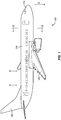
- FIG. 1 is a diagram of an aircraft 300 in an exemplary embodiment.
- aircraft 300 includes nose 310, wings 320, tail 340, and fuselage 330.
- FIG. 1 also illustrates a downward direction (Z) indicating the expected direction in which the force of gravity will pull objects, such as liquid water, onboard aircraft 300.
- Z downward direction
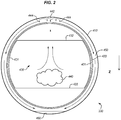
- FIG. 2 is a cross-section view of aircraft 300 indicated by reference number 2 in FIG. 1 .
- FIG. 2 illustrates a circular portion of aircraft fuselage 330, which includes floor 433, ceiling 432, and sidewalls 431. Passengers in aircraft 300 may congregate in cabin 430 during flight. As shown in FIG. 2 , inside of fuselage 330 (e.g., in cabin 430), respiration and other sources of water cause moisture 440 to enter the air in cabin 430. For example, warm exhaled air includes moisture 440, and rises upward. Some of this warm, moist air rises through ceiling 432. Furthermore, some warm air continues to rise upward through insulation 420 into a space 450 between insulation 420 and aircraft skin 410.
- ice 442 melts into water droplets 444, which travel through space 450 into drainage channel 460.
- space 450 has been substantially exaggerated in FIG. 2 in order to highlight the path through which droplets 444 are intended to travel.
- FIG. 3 is a diagram illustrating a section 500 of fuselage 330 of aircraft 300 in an exemplary embodiment.
- FIG. 3 is a view shown as reference number 3 in FIG. 1 .
- various structural components 510, 520, 530, 410) are illustrated without insulation for clarity.
- multiple stringers 520 connect frame elements 510 (e.g., ribs of the aircraft) together.
- Windows e.g., window 530
- penetrate through skin 410 and are illustrated for context to ensure clarity in understanding the view presented.
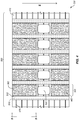
- FIG. 4 is a diagram illustrating section 500 of fuselage 330 with insulation in an exemplary embodiment.
- FIG. 4 also utilizes the view shown as reference number 3 in FIG. 1 .
- the various structural components (510, 520, 530, 410) depicted in FIG. 3 are now insulated.
- bays 560 formed between frame elements 510 are filled with insulating bay blankets 562.
- each frame element 510 is itself covered by an insulating liner (e.g., a cap strip) 512.
- Liner 512 is waterproof (e.g., impermeable to water, such that water cannot cross directly through the material of liner 512 from either the cabin 430 of aircraft 300 to skin 410, or from skin 410 of aircraft 300 to cabin 430).
- liner 512 prevents such moisture from dripping back into the cabin, instead draining moisture around the perimeter of the cabin 430 drainage channel 460 (e.g., a keel area).
- Liner 512 is also thermally insulating, ensuring that passengers within aircraft 300 do not experience substantial temperature drops when aircraft 300 travels at cruising altitude, and further ensuring that liquid water does not permeate through insulated liner 512 when flowing along insulated liner 512. Further discussion focuses on an insulated liner 512 and its corresponding frame element 510.
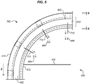
- FIG. 5 is a diagram illustrating a portion of an insulated frame element 510 of an aircraft in an exemplary embodiment.
- Frame element 510 is illustrated by the bold dashed lines of FIG. 5 , and is obscured by liner 512, bay blanket 562, and stringer 520.
- FIG. 5 is a view of a portion 700 of a frame element 510 situated at the top of aircraft 300, as shown in reference number 5 of FIG. 4 .
- FIG. 5 illustrates that multiple brackets (710, 712, 714) are attached to frame element 510.
- Brackets (710, 712, 714) may be used for any suitable purpose, such as for mounting air ducts or electrical wiring within aircraft 300.
- the brackets (710, 712, 714) penetrate through insulated liner 512, and therefore provide a pathway for droplets 444 to travel, allowing droplets 444 to drip from frame element 510 through ceiling 432 into the cabin 430 of aircraft 300.
- FIG. 6 is a diagram illustrating a cross-section of an insulated frame element 510 in an exemplary embodiment. Specifically, in this exemplary embodiment FIG. 6 is a cross-section of a portion of frame element 510 at the top of aircraft 300. FIG. 6 is represented on FIG. 5 by reference number 6. FIG. 6 illustrates an exemplary frame element 510 having an "S" shaped cross-section, but any suitable cross-section may be used for frame element 510.
- Brackets 710 are attached to frame element 510 via one or more via fasteners 910 (e.g., rivets, bolts, screws, etc.).
- Frame element 510 is surrounded by insulated liner 512.
- Liner 512 forms a cap strip around frame element 510, and liner 512 comprises two elongate/lengthwise insulators 912 and 913.
- the elongate/lengthwise dimension of insulators 912 and 913 extends into the page.
- frame element 510 extends hoopwise around fuselage 330 with liner 512 also extending in a hoopwise direction.
- Insulators 912 and 913 may be composed of a closed cell vinyl/nitrile foam, or other type of material.
- each insulator (912, 913) includes a corresponding elongate/lengthwise tab/lip (930, 940).
- tabs/lips (930, 940) extend towards frame element 510 (e.g., for about one inch), ensuring that water dripping from frame element 510 lands in channels 950 and 960, which are partially defined by tabs 930 and 940, and are partially defined by sidewalls/channel walls 922 and 923 of insulators 912 and 913.
- Droplets 444 within the channels 950 and 960 are drained along liner 512 proximate to frame element 510, instead of dripping out of liner 512. Hence, the cabin of aircraft 300 is not precipitated upon by droplets 444.
- FIG. 7 is a zoomed in view of a cross-section of an insulated frame element in an exemplary embodiment. Specifically, FIG. 7 corresponds with section 980 of FIG. 6 .
- FIG. 7 illustrates gap 990 located between distal ends 915 and 916 of insulators 912 and 913, which are substantially abutting each other (i.e., bordering and/or touching at certain locations). In FIG. 7 , gap 990 is due to a penetration of liner 512 that enables bracket 710 to protrude through liner 512 towards the inside of aircraft 300.
- FIG. 7 further illustrates fixation elements 1010 and 1020, which are attached to distal portions/ends/sides 932 and 942 of tabs 930 and 940, respectively.
- Fixation elements 1010 and 1020 may comprise discrete features such as buttons/snaps, or continuous features such as zippers, hook and loop fastener tape (e.g., VELCROTM), pressure sensitive adhesive strips, etc.
- Portions (932, 942) of tabs 930 and 940 act as complementary channel walls to channel walls 922 and 923 of FIG. 6 . Since tabs 930 and 940 are made of a waterproof material (e.g., vinyl), water cannot penetrate tabs 930 and 940, regardless of the narrow width of tabs 930 and 940. Tabs 930 and 940 may be attached to insulator 912 and 913 via any suitable waterproof means, such as gluing, waterproof stitching, being integrated together, etc. In short, waterproof tabs 930 and 940 prevent liquid from traveling through lengthwise gap 990 while waterproof tabs 930 and 940 are affixed to each other via fixation elements 1010 and 1020.
- a waterproof material e.g., vinyl
- FIG. 8 is a perspective view of a portion of a frame element 510 in an exemplary embodiment, represented by reference number 8 on FIG. 6 .
- FIG. 8 illustrates the elongate/lengthwise dimension L, and further illustrates how gap 990 is a lengthwise slit through which brackets 710 penetrate. Because tabs 930 and 940 can be affixed to each other (e.g., removably affixed), gap 990 is sealed/closed proximate to tabs 930 and 940. The seal is only broken when brackets 710 penetrate between tabs 930 and 940, through gap 990 defined by insulated liner 512.
- FIG. 9 is a diagram illustrating a cross-section of a further insulated frame element 510 in an exemplary embodiment. Specifically, FIG. 9 is a cross-section view of a frame element 510, represented on FIG. 5 by reference number 6.
- tab 930 is affixed via fixation element 1010 to fixation element 1020 of tab 1240.
- Tab 1240 includes base 1242, to which fixation element 1020 is attached, and arcing portion 1244, which overlaps distal portion 932 of tab 930. In this manner, water/moisture is diverted from flowing into gap 990, instead flowing into channels 950 and 960, which divert the water along the perimeter of aircraft 300.
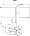
- FIG. 10 is a diagram illustrating a cross-section of a further insulated frame element in an exemplary embodiment.
- FIG. 10 is a cross-section view of frame element 510, represented on FIG. 5 by reference number 6.
- tab 930 is affixed twice to tab 1240. That is, tab 930 includes fixation element 1010 and 1310, and which are affixed to fixation elements 1020 and 1320 respectively.
- tab 1240 includes base 1242 (to which fixation element 1020 is attached), arcing portion 1244 (which overlaps tab 930), and flap 1246 (to which fixation element 1320 is attached).
- arcing portion 1244 is cuts at locations where brackets will be inserted between tabs 930 and 1200.
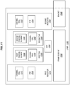
- FIG. 11 is a block diagram of an insulated frame element in an exemplary embodiment.
- frame element 1330 is attached to bracket 1340, and liner 1300 covers frame element 1330.
- Liner 1300 comprises a first insulator 1310, which itself includes a channel wall 1312, and an end 1314.
- First tab 1330 is attached to end 1314, and first tab 1330 includes a channel wall 1332, and a first fixation element 1334.
- Liner 1300 further comprises a second insulator 1320, which itself includes a channel wall 1322, and an end 1324.
- Second tab 1340 is attached to end 1324, and second tab 1340 includes a channel wall 1342, and a second fixation element 1344.
- First fixation element 1334 is removably attached to second fixation element 1344, covering gap 1350 in locations where bracket 1340 does not protrude through gap 1350.
- FIG. 12 is a flowchart illustrating a method for installing a liner in an exemplary embodiment.
- a technician identifies/selects a liner (i.e., liner 512 which exhibits enhanced drainage properties) to install onto a frame element 510.
- the technician installs the liner 512 onto frame element 510. This may comprise screwing, tying, or gluing liner 512 in place in order to affix liner 512 to frame element 510.
- the technician seals/affixes tabs of liner 512 to each other. This enables liner 512 to divert moisture dripping from frame element 510 into channels 950 and 960.
- exemplary method 100 may include specification and design 104 of the aircraft 102 and material procurement 106.
- component and subassembly manufacturing 108 and system integration 110 of the aircraft 102 takes place.
- the aircraft 102 may go through certification and delivery 112 in order to be placed in service 114.
- routine maintenance and service 116 which may also include modification, reconfiguration, refurbishment, and so on).
- the improved techniques and components described herein may be utilized such that materials for liners are procured in stage 106, then utilized in stage 108 in order to assemble the materials into a liner in stage 108.
- the assembled liner may be attached to a frame of an aircraft, and in stage 114 the liner within the aircraft enhances drainage within an interior 122 while the aircraft is operating.
- the liner may be replaced or repaired by technicians for the aircraft.
- a system integrator may include without limitation any number of aircraft manufacturers and major-system subcontractors; a third party may include without limitation any number of vendors, subcontractors, and suppliers; and an operator may be an airline, leasing company, military entity, service organization, and so on.
- the aircraft 102 produced by exemplary method 100 may include an airframe 118 with a plurality of systems 120 and an interior 122.
- high-level systems 120 include one or more of a propulsion system 124, an electrical system 126, a hydraulic system 126, and an environmental system 130. Any number of other systems may be included.
- an aerospace example is shown, the principles of the invention may be applied to other industries, such as the automotive industry.
- Apparatus and methods embodied herein may be employed during any one or more of the stages of the production and service method 100.
- components or subassemblies corresponding to production stage 108 may be fabricated or manufactured in a manner similar to components or subassemblies produced while the aircraft 102 is in service.
- one or more apparatus embodiments, method embodiments, or a combination thereof may be utilized during the production stages 108 and 110, for example, by substantially expediting assembly of or reducing the cost of an aircraft 102.
- apparatus embodiments, method embodiments, or a combination thereof may be utilized while the aircraft 102 is in service, for example and without limitation, to maintenance and service 116.
Landscapes
- Engineering & Computer Science (AREA)
- Aviation & Aerospace Engineering (AREA)
- Mechanical Engineering (AREA)
- Manufacturing & Machinery (AREA)
- Transportation (AREA)
- Casings For Electric Apparatus (AREA)
- Body Structure For Vehicles (AREA)
- Connection Of Plates (AREA)
Abstract
Description
- The disclosure relates to the field of insulation, and in particular, to insulation for aircraft.
- Aircraft may use insulation to prevent internal components from experiencing substantial temperature shifts when the aircraft changes elevation between landing and flight. For example, aircraft insulation in a cabin of a passenger aircraft ensures that passengers remain comfortable even when the temperature outside the aircraft varies substantially.
- While an aircraft is in flight, it is possible that some moisture may rise from the cabin through the insulation, and then condense out of the air and freeze to the inside of the skin of the aircraft above the ceiling of the passenger compartment. When the aircraft lands and moisture has frozen to the inner side of the skin of the aircraft, the moisture is exposed to warmer temperatures, and therefore melts. Most of the moisture is drained along the skin of the aircraft towards the bottom of the aircraft, without entering the cabin. However, in certain cases, some moisture may drip through the insulation into the cabin, which is undesirable for both passengers and cargo. Thus, enhanced techniques for handling moisture flow within an aircraft are desired.
- Embodiments described herein enhance aircraft insulation such as cap strips for the ribs/frame of an aircraft. A cap strip insulating a frame of an aircraft may include a lengthwise gap that enables brackets to protrude from the frame towards the interior of the aircraft. However, moisture will leak from the skin of the aircraft down the frame of the aircraft, and will drip through the lengthwise gap in the cap strip into the aircraft cabin. The cap strips described herein include tabs/protrusions/lips that are capable of substantially sealing such lengthwise gaps, reducing the amount of leaking moisture entering the aircraft cabin through such gaps. In short, dripping moisture is contained by the cap strip, and drains along drainage channels defined by the cap strip, without entering the aircraft cabin.
- One exemplary embodiment comprises a liner. The liner covers a frame element of an aircraft. The liner includes a first waterproof lip that is attached to a first insulator and protrudes towards the frame element. The first waterproof lip and the first insulator form a first drainage channel for the frame element. A second waterproof lip is attached to a second insulator and protrudes towards the frame element. The second waterproof lip and the second insulator form a second drainage channel for the frame element. The first waterproof lip and the second waterproof lip each include a lengthwise fixation element that attaches the first waterproof lip to the second waterproof lip, sealing at least a portion of the lengthwise gap.
- Another embodiment comprises a liner for a frame element of an aircraft fuselage. The liner includes elongate insulating portions covering the frame element along a length of the frame element, including ends that join to define a lengthwise slit between the elongate insulating portions. The liner also includes lengthwise waterproof tabs positioned on the ends of the insulating portions, each waterproof tab having a fixation element adapted to attach the waterproof tab to a fixation element of another waterproof tab. The waterproof tabs protrude towards the ends of the frame elements and divert liquid into channels within the liner while the waterproof tabs are affixed to each other via the fixation elements.
- Another embodiment is an apparatus that includes a frame element of an aircraft fuselage, multiple brackets fixedly attached to the frame element, and a cap strip liner for the frame element. The cap strip liner includes elongate insulating portions covering the frame element along a length of the frame element, having ends that define a lengthwise slit. The cap strip liner also includes lengthwise waterproof tabs positioned on the ends of the insulating portions, each waterproof tab having a fixation element adapted to attach the waterproof tab to a fixation element of another waterproof tab. The waterproof tabs prevent liquid from traveling through the lengthwise slit while the waterproof tabs are affixed to each other via the fixation elements.
- Another embodiment is a method. The method includes selecting a liner for a frame element of an aircraft and installing the liner onto the frame element. The method further includes affixing tabs of the liner to each other, thereby enabling the liner to divert moisture from the frame element into channels within the liner, the tabs each defining at least one wall of one of the channels.
- Other exemplary embodiments (e.g., methods and computer-readable media relating to the foregoing embodiments) may be described below. The features, functions, and advantages that have been discussed can be achieved independently in various embodiments or may be combined in yet other embodiments further details of which can be seen with reference to the following description and drawings.
- Some embodiments of the present disclosure are now described, by way of example only, and with reference to the accompanying drawings. The same reference number represents the same element or the same type of element on all drawings.
-
FIG. 1 is a diagram of an aircraft in an exemplary embodiment. -
FIG. 2 is a diagram illustrating moisture flow in an aircraft in an exemplary embodiment. -
FIG. 3 is a diagram illustrating section of aircraft fuselage in an exemplary embodiment. -
FIG. 4 is a diagram illustrating section of insulated aircraft fuselage in an exemplary embodiment. -
FIG. 5 is a diagram illustrating a portion of an insulated frame element in an exemplary embodiment. -
FIG. 6 is a diagram illustrating a cross-section of an insulated frame element in an exemplary embodiment. -
FIG. 7 is a zoomed in view of a cross-section of an insulated frame element in an exemplary embodiment. -
FIG. 8 is a perspective view of a portion of an insulated frame element in an exemplary embodiment. -
FIG. 9 is a diagram illustrating a cross-section of a further insulated frame element in an exemplary embodiment. -
FIG. 10 is a diagram illustrating a cross-section of a further insulated frame element in an exemplary embodiment. -
FIG. 11 is a block diagram of an insulated frame element in an exemplary embodiment. -
FIG. 12 is a flowchart illustrating a method for installing a liner in an exemplary embodiment. -
FIG. 13 is a flow diagram of aircraft production and service methodology in an exemplary embodiment. -
FIG. 14 is a block diagram of an aircraft in an exemplary embodiment. - The figures and the following description illustrate specific exemplary embodiments of the disclosure. It will thus be appreciated that those skilled in the art will be able to devise various arrangements that, although not explicitly described or shown herein, embody the principles of the disclosure and are included within the scope of the disclosure. Furthermore, any examples described herein are intended to aid in understanding the principles of the disclosure, and are to be construed as being without limitation to such specifically recited examples and conditions. As a result, the disclosure is not limited to the specific embodiments or examples described below, but by the claims and their equivalents.
-
FIGS. 1-5 illustrate moisture flow in an exemplary aircraft, whileFIGS. 6-10 illustrate systems that reduce the potential for condensed moisture to enter the interior of a fuselage of such an exemplary aircraft.FIG. 1 is a diagram of anaircraft 300 in an exemplary embodiment. According toFIG. 1 ,aircraft 300 includesnose 310,wings 320,tail 340, andfuselage 330.FIG. 1 also illustrates a downward direction (Z) indicating the expected direction in which the force of gravity will pull objects, such as liquid water, onboardaircraft 300. -
FIG. 2 is a cross-section view ofaircraft 300 indicated byreference number 2 inFIG. 1 .FIG. 2 illustrates a circular portion ofaircraft fuselage 330, which includesfloor 433,ceiling 432, andsidewalls 431. Passengers inaircraft 300 may congregate incabin 430 during flight. As shown inFIG. 2 , inside of fuselage 330 (e.g., in cabin 430), respiration and other sources ofwater cause moisture 440 to enter the air incabin 430. For example, warm exhaled air includesmoisture 440, and rises upward. Some of this warm, moist air rises throughceiling 432. Furthermore, some warm air continues to rise upward throughinsulation 420 into aspace 450 betweeninsulation 420 andaircraft skin 410. - At
high altitude skin 410, cooled by the outside air, is below freezing, causing water to condense out of the air and freeze ontoskin 410, as shown byice 442. Upon descending to a lower altitude (e.g., for landing)ice 442 melts intowater droplets 444, which travel throughspace 450 intodrainage channel 460. When there are gaps ininsulation 420 somewater droplets 444 will melt fromice 442, pass throughinsulation 420 and drip fromceiling 432 onto passengers, which is undesirable. The size ofspace 450 has been substantially exaggerated inFIG. 2 in order to highlight the path through whichdroplets 444 are intended to travel. -
FIG. 3 is a diagram illustrating asection 500 offuselage 330 ofaircraft 300 in an exemplary embodiment.FIG. 3 is a view shown asreference number 3 inFIG. 1 . InFIG. 3 , various structural components (510, 520, 530, 410) are illustrated without insulation for clarity. Specifically,multiple stringers 520 connect frame elements 510 (e.g., ribs of the aircraft) together. Windows (e.g., window 530) penetrate throughskin 410, and are illustrated for context to ensure clarity in understanding the view presented. -
FIG. 4 is adiagram illustrating section 500 offuselage 330 with insulation in an exemplary embodiment.FIG. 4 also utilizes the view shown asreference number 3 inFIG. 1 . InFIG. 4 , the various structural components (510, 520, 530, 410) depicted inFIG. 3 are now insulated. Specifically,bays 560 formed betweenframe elements 510 are filled with insulating bay blankets 562. Meanwhile, eachframe element 510 is itself covered by an insulating liner (e.g., a cap strip) 512.Liner 512 is waterproof (e.g., impermeable to water, such that water cannot cross directly through the material ofliner 512 from either thecabin 430 ofaircraft 300 toskin 410, or fromskin 410 ofaircraft 300 to cabin 430). Although some moisture may travel between gaps inliner 512,liner 512 prevents such moisture from dripping back into the cabin, instead draining moisture around the perimeter of thecabin 430 drainage channel 460 (e.g., a keel area).Liner 512 is also thermally insulating, ensuring that passengers withinaircraft 300 do not experience substantial temperature drops whenaircraft 300 travels at cruising altitude, and further ensuring that liquid water does not permeate through insulatedliner 512 when flowing alonginsulated liner 512. Further discussion focuses on aninsulated liner 512 and itscorresponding frame element 510. -
FIG. 5 is a diagram illustrating a portion of aninsulated frame element 510 of an aircraft in an exemplary embodiment.Frame element 510 is illustrated by the bold dashed lines ofFIG. 5 , and is obscured byliner 512,bay blanket 562, andstringer 520. Specifically,FIG. 5 is a view of aportion 700 of aframe element 510 situated at the top ofaircraft 300, as shown inreference number 5 ofFIG. 4 .FIG. 5 illustrates that multiple brackets (710, 712, 714) are attached to frameelement 510. Brackets (710, 712, 714) may be used for any suitable purpose, such as for mounting air ducts or electrical wiring withinaircraft 300. The brackets (710, 712, 714) penetrate through insulatedliner 512, and therefore provide a pathway fordroplets 444 to travel, allowingdroplets 444 to drip fromframe element 510 throughceiling 432 into thecabin 430 ofaircraft 300. -
FIG. 6 is a diagram illustrating a cross-section of aninsulated frame element 510 in an exemplary embodiment. Specifically, in this exemplary embodimentFIG. 6 is a cross-section of a portion offrame element 510 at the top ofaircraft 300.FIG. 6 is represented onFIG. 5 byreference number 6.FIG. 6 illustrates anexemplary frame element 510 having an "S" shaped cross-section, but any suitable cross-section may be used forframe element 510.Brackets 710 are attached to frameelement 510 via one or more via fasteners 910 (e.g., rivets, bolts, screws, etc.). -
Frame element 510 is surrounded byinsulated liner 512.Liner 512 forms a cap strip aroundframe element 510, andliner 512 comprises two elongate/lengthwise insulators insulators frame element 510 extends hoopwise aroundfuselage 330 withliner 512 also extending in a hoopwise direction.Insulators - As
water droplets 444 drip down in the Z direction fromframe element 510, they may drip intochannels brackets 710 extend). To prevent moisture from pooling neargap 990 and dripping out ofinsulated liner 512, each insulator (912, 913) includes a corresponding elongate/lengthwise tab/lip (930, 940). These tabs/lips (930, 940) extend towards frame element 510 (e.g., for about one inch), ensuring that water dripping fromframe element 510 lands inchannels tabs channel walls insulators Droplets 444 within thechannels liner 512 proximate to frameelement 510, instead of dripping out ofliner 512. Hence, the cabin ofaircraft 300 is not precipitated upon bydroplets 444. -
FIG. 7 is a zoomed in view of a cross-section of an insulated frame element in an exemplary embodiment. Specifically,FIG. 7 corresponds withsection 980 ofFIG. 6 .FIG. 7 illustratesgap 990 located betweendistal ends insulators FIG. 7 ,gap 990 is due to a penetration ofliner 512 that enablesbracket 710 to protrude throughliner 512 towards the inside ofaircraft 300.FIG. 7 further illustratesfixation elements sides tabs Fixation elements - Portions (932, 942) of
tabs walls FIG. 6 . Sincetabs tabs tabs Tabs insulator waterproof tabs lengthwise gap 990 whilewaterproof tabs fixation elements -
FIG. 8 is a perspective view of a portion of aframe element 510 in an exemplary embodiment, represented byreference number 8 onFIG. 6 .FIG. 8 illustrates the elongate/lengthwise dimension L, and further illustrates howgap 990 is a lengthwise slit through whichbrackets 710 penetrate. Becausetabs gap 990 is sealed/closed proximate totabs brackets 710 penetrate betweentabs gap 990 defined byinsulated liner 512. - Using the techniques shown herein, moisture is prevented from leaking along
gap 990 for an insulated liner offrame element 510 because the moisture is drawn off/diverted into channels. Locations for potential leaks are therefore drastically reduced, and are limited to locations whereinbrackets 710 protrude throughframe element 510. This dramatically reduces the amount of intrusion of moisture into a cabin of an aircraft, ensuring that passenger comfort is ensured and precipitation into the cabin is not a factor. -
FIG. 9 is a diagram illustrating a cross-section of a further insulatedframe element 510 in an exemplary embodiment. Specifically,FIG. 9 is a cross-section view of aframe element 510, represented onFIG. 5 byreference number 6. InFIG. 9 ,tab 930 is affixed viafixation element 1010 tofixation element 1020 oftab 1240.Tab 1240 includesbase 1242, to whichfixation element 1020 is attached, and arcingportion 1244, which overlapsdistal portion 932 oftab 930. In this manner, water/moisture is diverted from flowing intogap 990, instead flowing intochannels aircraft 300. In short, moisture that would otherwise drop in betweentabs 930 and 1200, then adhere and travel intogap 990, now flows either to the left oftab 930 or the right oftab 1240. In this embodiment, arcingportion 1244 is cut at location where brackets will be inserted betweentabs bracket 710, provides for enhanced levels of moisture control and drainage. -
FIG. 10 is a diagram illustrating a cross-section of a further insulated frame element in an exemplary embodiment. Specifically,FIG. 10 is a cross-section view offrame element 510, represented onFIG. 5 byreference number 6. InFIG. 10 ,tab 930 is affixed twice totab 1240. That is,tab 930 includesfixation element fixation elements tab 1240 includes base 1242 (to whichfixation element 1020 is attached), arcing portion 1244 (which overlaps tab 930), and flap 1246 (to whichfixation element 1320 is attached). In this manner, water that would otherwise touch betweentabs gap 990, now flows either to the left oftab 930 or the right oftab 1240. In this embodiment, arcingportion 1244 is cuts at locations where brackets will be inserted betweentabs 930 and 1200. -
FIG. 11 is a block diagram of an insulated frame element in an exemplary embodiment. Specifically,frame element 1330 is attached tobracket 1340, andliner 1300 coversframe element 1330.Liner 1300 comprises afirst insulator 1310, which itself includes achannel wall 1312, and anend 1314.First tab 1330 is attached to end 1314, andfirst tab 1330 includes achannel wall 1332, and afirst fixation element 1334.Liner 1300 further comprises asecond insulator 1320, which itself includes achannel wall 1322, and anend 1324.Second tab 1340 is attached to end 1324, andsecond tab 1340 includes achannel wall 1342, and asecond fixation element 1344.First fixation element 1334 is removably attached tosecond fixation element 1344, coveringgap 1350 in locations wherebracket 1340 does not protrude throughgap 1350. -
FIG. 12 is a flowchart illustrating a method for installing a liner in an exemplary embodiment. According toFIG. 12 , instep 1202, a technician identifies/selects a liner (i.e.,liner 512 which exhibits enhanced drainage properties) to install onto aframe element 510. Instep 1204, the technician installs theliner 512 ontoframe element 510. This may comprise screwing, tying, or gluingliner 512 in place in order to affixliner 512 to frameelement 510. Instep 1206, the technician seals/affixes tabs ofliner 512 to each other. This enablesliner 512 to divert moisture dripping fromframe element 510 intochannels - Referring more particularly to the drawings, embodiments of the disclosure may be described in the context of an aircraft manufacturing and
service method 100 as shown inFIG. 13 and anaircraft 102 as shown inFIG. 14 . During pre-production,exemplary method 100 may include specification anddesign 104 of theaircraft 102 andmaterial procurement 106. During production, component andsubassembly manufacturing 108 andsystem integration 110 of theaircraft 102 takes place. Thereafter, theaircraft 102 may go through certification anddelivery 112 in order to be placed inservice 114. While in service by a customer, theaircraft 102 is scheduled for routine maintenance and service 116 (which may also include modification, reconfiguration, refurbishment, and so on). In various embodiments, the improved techniques and components described herein may be utilized such that materials for liners are procured instage 106, then utilized instage 108 in order to assemble the materials into a liner instage 108. Instage 110, the assembled liner may be attached to a frame of an aircraft, and instage 114 the liner within the aircraft enhances drainage within an interior 122 while the aircraft is operating. Instage 116, the liner may be replaced or repaired by technicians for the aircraft. - Each of the processes of
method 100 may be performed or carried out by a system integrator, a third party, and/or an operator (e.g., a customer). For the purposes of this description, a system integrator may include without limitation any number of aircraft manufacturers and major-system subcontractors; a third party may include without limitation any number of vendors, subcontractors, and suppliers; and an operator may be an airline, leasing company, military entity, service organization, and so on. - As shown in
FIG. 14 , theaircraft 102 produced byexemplary method 100 may include anairframe 118 with a plurality ofsystems 120 and an interior 122. Examples of high-level systems 120 include one or more of apropulsion system 124, anelectrical system 126, ahydraulic system 126, and anenvironmental system 130. Any number of other systems may be included. Although an aerospace example is shown, the principles of the invention may be applied to other industries, such as the automotive industry. - Apparatus and methods embodied herein may be employed during any one or more of the stages of the production and
service method 100. For example, components or subassemblies corresponding toproduction stage 108 may be fabricated or manufactured in a manner similar to components or subassemblies produced while theaircraft 102 is in service. Also, one or more apparatus embodiments, method embodiments, or a combination thereof may be utilized during the production stages 108 and 110, for example, by substantially expediting assembly of or reducing the cost of anaircraft 102. Similarly, one or more of apparatus embodiments, method embodiments, or a combination thereof may be utilized while theaircraft 102 is in service, for example and without limitation, to maintenance andservice 116. - Thus, in summary, according to a first aspect of the present invention there is provided:
- Clause A1. An apparatus comprising:
- a liner configured to cover a frame element of an aircraft, the liner comprising:
- a first waterproof lip that is attached to a first insulator and protrudes towards the frame element, the first waterproof lip and the first insulator form a first drainage channel for the frame element; and
- a second waterproof lip that is attached to a second insulator and protrudes towards the frame element, the second waterproof lip and the second insulator form a second drainage channel for the frame element,
- a liner configured to cover a frame element of an aircraft, the liner comprising:
- Clause A2. The apparatus of clause A1 wherein:
- the fixation elements of the first waterproof lip and the second waterproof lip are detachably affixed to each other, enabling brackets extending from the frame element to protrude through the liner via the lengthwise gap.
- Clause A3. The apparatus of clause A2 wherein:
- the fixation elements are continuous features proximate to the lengthwise gap.
- Clause A4. The apparatus of any of clauses A1 to A3 wherein:
- the frame element comprises a portion of a fuselage of the aircraft.
- Clause A5. The apparatus of any of clauses A1 to A4 wherein:
- the fixation elements comprise hook and loop fasteners.
- Clause A6. The apparatus of any of clauses A1 to A5 wherein:
- the fixation elements comprise pressure sensitive adhesives.
- Clause A7. The apparatus of any of clauses A1 to A6 wherein:
- the first waterproof lip overlaps a distal portion of the second waterproof lip.
- Clause A8. The apparatus of clause A7 wherein:
- the first waterproof lip overlaps a left side and a right side of the second waterproof lip, and
- the first waterproof lip comprises two lengthwise fixation elements, that each correspond with a different side of the second waterproof tab.
- Clause A9. The apparatus of any of clauses A1 to A8 wherein:
- the drainage channels comprise arcuate pathways following a length of the frame element.
- Clause A10. The apparatus of any of clauses A1 to A9 wherein:
- the first insulator is configured to cover a left side of the frame element along a lengthwise direction,
- the second insulator is configured to cover a right side of the frame element along the lengthwise direction, and
- the first insulator comprises a first lengthwise end and the second insulator comprises a second lengthwise end abutting the first lengthwise end, forming a lengthwise gap in the liner between the first lengthwise end and the second lengthwise end.
- According to a further aspect of the present invention, there is provided:
- Clause B1. An apparatus comprising:
- a liner for a frame element of an aircraft fuselage, the liner comprising:
- elongate insulating portions covering the frame element along a length of the frame element, comprising ends that join to define a lengthwise slit between the elongate insulating portions; and
- lengthwise waterproof tabs positioned on the ends of the insulating portions, each waterproof tab comprising a fixation element adapted to attach the waterproof tab to a fixation element of another waterproof tab,
- a liner for a frame element of an aircraft fuselage, the liner comprising:
- Clause B2. The apparatus of clause B1 wherein:
- the fixation elements of the first waterproof tab and the second waterproof tab are detachably affixed to each other, enabling brackets extending from the frame element to protrude through the liner via the lengthwise slit.
- Clause B3. The apparatus of clause B2 wherein:
- the fixation elements are continuous features proximate to the lengthwise slit.
- Clause B4. The apparatus of any of clauses B1 to B3 wherein:
- the liner comprises an insulated cap strip, attached to an insulated bay blanket of the fuselage.
- Clause B5. The apparatus of any of clauses B1 to B4 wherein:
- the fixation elements comprise hook and loop fasteners.
- Clause B6. The apparatus of any of clauses B1 to B5 wherein:
- the fixation elements comprise pressure sensitive adhesives.
- Clause B7. The apparatus of any of clauses B1 to B6 wherein:
- one of the waterproof tabs overlaps a distal portion of the other waterproof tab.
- Clause B8. The apparatus of any of clauses B1 to B7 wherein:
- one of the waterproof tabs overlaps a left and a right side of the other waterproof tab, and
- each of the waterproof tabs comprises two fixation elements.
- Clause B9. The apparatus of clause B8 wherein:
- each of the channels comprises an arcuate pathway following the frame element.
- According to a further aspect of the present invention, there is provided:
- Clause C1. An apparatus comprising:
- a frame element of an aircraft fuselage;
- multiple brackets fixedly attached to the frame element; and
- a cap strip liner for the frame element, comprising:
- elongate insulating portions covering the frame element along a length of the frame element, comprising ends that define a lengthwise slit; and
- lengthwise waterproof tabs positioned on the ends of the insulating portions, each waterproof tab comprising a fixation element adapted to attach the waterproof tab to a fixation element of another waterproof tab,
- Clause C2. The apparatus of clause C1 wherein:
- the fixation elements of the first waterproof tab and the second waterproof tab are detachably affixed to each other, enabling brackets extending from the rib to protrude through the liner via the lengthwise slit.
- According to a further aspect of the present invention, there is provided:
- Clause D1. A method comprising:
- selecting a liner for a frame element of an aircraft;
- installing the liner onto the frame element; and
- affixing tabs of the liner to each other thereby enabling the liner to divert moisture from the frame element into channels within the liner, the tabs each defining at least one wall of one of the channels.
- Clause D2. The method of clause D1, wherein:
- affixing the tabs of the liner comprises removably affixing the tabs of the liner to each other via fixation elements of the tabs.
- Clause D3. The method of clause D1 or D2, wherein:
- each tab protrudes from an end of the liner towards the frame element.
- Although specific embodiments are described herein, the scope of the disclosure is not limited to those specific embodiments. The scope of the disclosure is defined by the following claims and any equivalents thereof.
Claims (13)
- An apparatus comprising:a liner configured to cover a frame element of an aircraft, the liner comprising:a first waterproof lip that is attached to a first insulator and protrudes towards the frame element, the first waterproof lip and the first insulator form a first drainage channel for the frame element; anda second waterproof lip that is attached to a second insulator and protrudes towards the frame element, the second waterproof lip and the second insulator form a second drainage channel for the frame element,the first waterproof lip and the second waterproof lip each comprise a lengthwise fixation element that attaches the first waterproof lip to the second waterproof lip, sealing at least a portion of the lengthwise gap.
- The apparatus of claim 1 wherein:the fixation elements of the first waterproof lip and the second waterproof lip are detachably affixed to each other, enabling brackets extending from the frame element to protrude through the liner via the lengthwise gap.
- The apparatus of claim 2 wherein:the fixation elements are continuous features proximate to the lengthwise gap.
- The apparatus of any preceding claims wherein:the frame element comprises a portion of a fuselage of the aircraft.
- The apparatus of any preceding claims wherein:the fixation elements comprise hook and loop fasteners.
- The apparatus of any preceding claims wherein:the fixation elements comprise pressure sensitive adhesives.
- The apparatus of any preceding claim wherein:the first waterproof lip overlaps a distal portion of the second waterproof lip.
- The apparatus of claim 7 wherein:the first waterproof lip overlaps a left side and a right side of the second waterproof lip, andthe first waterproof lip comprises two lengthwise fixation elements, that each correspond with a different side of the second waterproof tab.
- The apparatus of any preceding claim wherein:the drainage channels comprise arcuate pathways following a length of the frame element.
- The apparatus of any preceding claim wherein:the first insulator is configured to cover a left side of the frame element along a lengthwise direction,the second insulator is configured to cover a right side of the frame element along the lengthwise direction, andthe first insulator comprises a first lengthwise end and the second insulator comprises a second lengthwise end abutting the first lengthwise end, forming a lengthwise gap in the liner between the first lengthwise end and the second lengthwise end.
- A method comprising:selecting a liner for a frame element of an aircraft;installing the liner onto the frame element; andaffixing tabs of the liner to each other thereby enabling the liner to divert moisture from the frame element into channels within the liner, the tabs each defining at least one wall of one of the channels.
- The method of claim 11, wherein:affixing the tabs of the liner comprises removably affixing the tabs of the liner to each other via fixation elements of the tabs.
- The method of claim 11 or claim 12, wherein:each tab protrudes from an end of the liner towards the frame element.
Applications Claiming Priority (1)
| Application Number | Priority Date | Filing Date | Title |
|---|---|---|---|
| US14/885,041 US10023285B2 (en) | 2015-10-16 | 2015-10-16 | Frame insulation providing enhanced drainage features |
Publications (2)
| Publication Number | Publication Date |
|---|---|
| EP3156322A1 true EP3156322A1 (en) | 2017-04-19 |
| EP3156322B1 EP3156322B1 (en) | 2022-12-07 |
Family
ID=57184305
Family Applications (1)
| Application Number | Title | Priority Date | Filing Date |
|---|---|---|---|
| EP16193739.6A Active EP3156322B1 (en) | 2015-10-16 | 2016-10-13 | Frame insulation providing enhanced drainage features |
Country Status (3)
| Country | Link |
|---|---|
| US (1) | US10023285B2 (en) |
| EP (1) | EP3156322B1 (en) |
| BR (1) | BR102016020991B1 (en) |
Cited By (1)
| Publication number | Priority date | Publication date | Assignee | Title |
|---|---|---|---|---|
| EP3476713A1 (en) * | 2017-10-30 | 2019-05-01 | The Boeing Company | Devices and methods to capture moisture from a structural member |
Families Citing this family (5)
| Publication number | Priority date | Publication date | Assignee | Title |
|---|---|---|---|---|
| US10023286B2 (en) * | 2015-11-19 | 2018-07-17 | The Boeing Company | Aircraft bay blankets that provide enhanced drainage features |
| US10988230B2 (en) * | 2017-06-19 | 2021-04-27 | The Boeing Company | Passive moisture management bladder in an aircraft |
| US12269574B2 (en) * | 2020-02-11 | 2025-04-08 | The Boeing Company | Methods for forming liquid flow paths on a surface of a structure |
| US12275520B2 (en) * | 2020-02-11 | 2025-04-15 | The Boeing Company | Liquid-diverting panel assemblies |
| US11320296B2 (en) | 2020-03-30 | 2022-05-03 | The Boeing Company | Test cage for testing a gap in a vehicle |
Citations (5)
| Publication number | Priority date | Publication date | Assignee | Title |
|---|---|---|---|---|
| DE2035807A1 (en) * | 1970-07-18 | 1972-01-27 | Vereinigte Flugtechnische Werke-Fokker GmbH, 2800 Bremen | Component for sound and heat insulation |
| DE9200494U1 (en) * | 1992-01-17 | 1992-03-12 | Deutsche Airbus GmbH, 2000 Hamburg | Sealing profile for cladding parts |
| US5901519A (en) * | 1995-09-19 | 1999-05-11 | Wilson; Thomas Gray | Helicopter interior |
| DE102010006564A1 (en) * | 2010-02-02 | 2011-08-04 | Airbus Operations GmbH, 21129 | Condensation pass reducing insulation package for thermal and acoustic insulation einr vehicle cabin |
| US20150274278A1 (en) * | 2014-03-25 | 2015-10-01 | Gulfstream Aerospace Corporation | Over-frame blanket assemblies and methods of installation in fuselage assemblies |
Family Cites Families (4)
| Publication number | Priority date | Publication date | Assignee | Title |
|---|---|---|---|---|
| AT505901B1 (en) * | 2008-04-02 | 2009-05-15 | Facc Ag | CEILING PANEL FOR THE COVERING OF THE INTERIOR OF VEHICLES |
| JP5309922B2 (en) * | 2008-11-20 | 2013-10-09 | アイシン精機株式会社 | Shade device for vehicle |
| WO2010125675A1 (en) * | 2009-04-30 | 2010-11-04 | Ykk株式会社 | Fastening member |
| US8567599B2 (en) * | 2010-01-26 | 2013-10-29 | Modulr Llc | Multifunctional electronic device case |
-
2015
- 2015-10-16 US US14/885,041 patent/US10023285B2/en active Active
-
2016
- 2016-09-12 BR BR102016020991-9A patent/BR102016020991B1/en active IP Right Grant
- 2016-10-13 EP EP16193739.6A patent/EP3156322B1/en active Active
Patent Citations (5)
| Publication number | Priority date | Publication date | Assignee | Title |
|---|---|---|---|---|
| DE2035807A1 (en) * | 1970-07-18 | 1972-01-27 | Vereinigte Flugtechnische Werke-Fokker GmbH, 2800 Bremen | Component for sound and heat insulation |
| DE9200494U1 (en) * | 1992-01-17 | 1992-03-12 | Deutsche Airbus GmbH, 2000 Hamburg | Sealing profile for cladding parts |
| US5901519A (en) * | 1995-09-19 | 1999-05-11 | Wilson; Thomas Gray | Helicopter interior |
| DE102010006564A1 (en) * | 2010-02-02 | 2011-08-04 | Airbus Operations GmbH, 21129 | Condensation pass reducing insulation package for thermal and acoustic insulation einr vehicle cabin |
| US20150274278A1 (en) * | 2014-03-25 | 2015-10-01 | Gulfstream Aerospace Corporation | Over-frame blanket assemblies and methods of installation in fuselage assemblies |
Cited By (2)
| Publication number | Priority date | Publication date | Assignee | Title |
|---|---|---|---|---|
| EP3476713A1 (en) * | 2017-10-30 | 2019-05-01 | The Boeing Company | Devices and methods to capture moisture from a structural member |
| US10793248B2 (en) | 2017-10-30 | 2020-10-06 | The Boeing Company | Devices and methods to capture moisture from a structural member |
Also Published As
| Publication number | Publication date |
|---|---|
| BR102016020991B1 (en) | 2022-11-29 |
| BR102016020991A2 (en) | 2017-05-30 |
| EP3156322B1 (en) | 2022-12-07 |
| US10023285B2 (en) | 2018-07-17 |
| US20170106965A1 (en) | 2017-04-20 |
Similar Documents
| Publication | Publication Date | Title |
|---|---|---|
| US10556663B2 (en) | Aircraft bay blankets that provide enhanced drainage features | |
| EP3156322B1 (en) | Frame insulation providing enhanced drainage features | |
| US8727281B2 (en) | Condensed water decreasing insulation package for thermal and acoustic insulation of a vehicle cabin | |
| EP2718181B1 (en) | System and method for insulating a frame member | |
| EP3348468B1 (en) | Continuous insulation blanket cap strip assemblies and methods of using same | |
| RU2737079C2 (en) | Methods and devices for shaping insulating mats and their installation in vehicle compartment | |
| US20190233126A1 (en) | Temperature monitoring unit for aircraft wing structure and associated installation method | |
| EP1449764B1 (en) | Quick-install insulation | |
| EP3290331B1 (en) | Moisture path close-out and thermal control system and methods of assembling same | |
| BR112015031474B1 (en) | METHOD AND SYSTEM FOR ANTI-FREEZE/DEFROST OF AN AIRCRAFT EQUIPMENT, AND, AIRCRAFT AND AIRCRAFT DOOR EQUIPPED WITH AN ANTI-FREEZE/DEFROST SYSTEM. | |
| CA2947185C (en) | Aircraft bay blankets that provide enhanced drainage features | |
| US10059427B2 (en) | Over-frame blanket assemblies and methods of installation in fuselage assemblies | |
| EP2899127A1 (en) | Dehumidification system for use in a vehicle and method of assembling thereof | |
| CN111452985B (en) | System and method for passively removing moisture from air within a vehicle | |
| US10442518B2 (en) | Moisture diversion systems and methods of using same | |
| EP4197903A1 (en) | Thermal barrier curtain systems especially useful for thermally isolating interior cabin zones of cargo transport aircraft | |
| US10093407B2 (en) | Enhanced water capture systems for aircraft interiors | |
| US20250058867A1 (en) | Insulation Blanket Assemblies and Methods | |
| BR102017024956B1 (en) | BLANKET SET, INSULATION LAYER OF AN AIRCRAFT AND METHOD OF USE OF AT LEAST ONE INSULATION BLANKET SET |
Legal Events
| Date | Code | Title | Description |
|---|---|---|---|
| PUAI | Public reference made under article 153(3) epc to a published international application that has entered the european phase |
Free format text: ORIGINAL CODE: 0009012 |
|
| STAA | Information on the status of an ep patent application or granted ep patent |
Free format text: STATUS: REQUEST FOR EXAMINATION WAS MADE |
|
| 17P | Request for examination filed |
Effective date: 20161013 |
|
| AK | Designated contracting states |
Kind code of ref document: A1 Designated state(s): AL AT BE BG CH CY CZ DE DK EE ES FI FR GB GR HR HU IE IS IT LI LT LU LV MC MK MT NL NO PL PT RO RS SE SI SK SM TR |
|
| AX | Request for extension of the european patent |
Extension state: BA ME |
|
| STAA | Information on the status of an ep patent application or granted ep patent |
Free format text: STATUS: EXAMINATION IS IN PROGRESS |
|
| 17Q | First examination report despatched |
Effective date: 20190611 |
|
| GRAP | Despatch of communication of intention to grant a patent |
Free format text: ORIGINAL CODE: EPIDOSNIGR1 |
|
| STAA | Information on the status of an ep patent application or granted ep patent |
Free format text: STATUS: GRANT OF PATENT IS INTENDED |
|
| INTG | Intention to grant announced |
Effective date: 20220603 |
|
| RIN1 | Information on inventor provided before grant (corrected) |
Inventor name: ZAKHAROVA, IRINA ALEKSEEVNA Inventor name: TIBAYAN, JESSE VITALEZ Inventor name: DICKSON, JENNIFER LYNN |
|
| GRAS | Grant fee paid |
Free format text: ORIGINAL CODE: EPIDOSNIGR3 |
|
| GRAA | (expected) grant |
Free format text: ORIGINAL CODE: 0009210 |
|
| STAA | Information on the status of an ep patent application or granted ep patent |
Free format text: STATUS: THE PATENT HAS BEEN GRANTED |
|
| AK | Designated contracting states |
Kind code of ref document: B1 Designated state(s): AL AT BE BG CH CY CZ DE DK EE ES FI FR GB GR HR HU IE IS IT LI LT LU LV MC MK MT NL NO PL PT RO RS SE SI SK SM TR |
|
| REG | Reference to a national code |
Ref country code: GB Ref legal event code: FG4D |
|
| REG | Reference to a national code |
Ref country code: CH Ref legal event code: EP Ref country code: AT Ref legal event code: REF Ref document number: 1536165 Country of ref document: AT Kind code of ref document: T Effective date: 20221215 |
|
| REG | Reference to a national code |
Ref country code: DE Ref legal event code: R096 Ref document number: 602016076748 Country of ref document: DE |
|
| REG | Reference to a national code |
Ref country code: IE Ref legal event code: FG4D |
|
| RAP4 | Party data changed (patent owner data changed or rights of a patent transferred) |
Owner name: THE BOEING COMPANY |
|
| REG | Reference to a national code |
Ref country code: LT Ref legal event code: MG9D |
|
| REG | Reference to a national code |
Ref country code: NL Ref legal event code: MP Effective date: 20221207 |
|
| PG25 | Lapsed in a contracting state [announced via postgrant information from national office to epo] |
Ref country code: SE Free format text: LAPSE BECAUSE OF FAILURE TO SUBMIT A TRANSLATION OF THE DESCRIPTION OR TO PAY THE FEE WITHIN THE PRESCRIBED TIME-LIMIT Effective date: 20221207 Ref country code: NO Free format text: LAPSE BECAUSE OF FAILURE TO SUBMIT A TRANSLATION OF THE DESCRIPTION OR TO PAY THE FEE WITHIN THE PRESCRIBED TIME-LIMIT Effective date: 20230307 Ref country code: LT Free format text: LAPSE BECAUSE OF FAILURE TO SUBMIT A TRANSLATION OF THE DESCRIPTION OR TO PAY THE FEE WITHIN THE PRESCRIBED TIME-LIMIT Effective date: 20221207 Ref country code: FI Free format text: LAPSE BECAUSE OF FAILURE TO SUBMIT A TRANSLATION OF THE DESCRIPTION OR TO PAY THE FEE WITHIN THE PRESCRIBED TIME-LIMIT Effective date: 20221207 Ref country code: ES Free format text: LAPSE BECAUSE OF FAILURE TO SUBMIT A TRANSLATION OF THE DESCRIPTION OR TO PAY THE FEE WITHIN THE PRESCRIBED TIME-LIMIT Effective date: 20221207 |
|
| REG | Reference to a national code |
Ref country code: AT Ref legal event code: MK05 Ref document number: 1536165 Country of ref document: AT Kind code of ref document: T Effective date: 20221207 |
|
| PG25 | Lapsed in a contracting state [announced via postgrant information from national office to epo] |
Ref country code: RS Free format text: LAPSE BECAUSE OF FAILURE TO SUBMIT A TRANSLATION OF THE DESCRIPTION OR TO PAY THE FEE WITHIN THE PRESCRIBED TIME-LIMIT Effective date: 20221207 Ref country code: PL Free format text: LAPSE BECAUSE OF FAILURE TO SUBMIT A TRANSLATION OF THE DESCRIPTION OR TO PAY THE FEE WITHIN THE PRESCRIBED TIME-LIMIT Effective date: 20221207 Ref country code: LV Free format text: LAPSE BECAUSE OF FAILURE TO SUBMIT A TRANSLATION OF THE DESCRIPTION OR TO PAY THE FEE WITHIN THE PRESCRIBED TIME-LIMIT Effective date: 20221207 Ref country code: HR Free format text: LAPSE BECAUSE OF FAILURE TO SUBMIT A TRANSLATION OF THE DESCRIPTION OR TO PAY THE FEE WITHIN THE PRESCRIBED TIME-LIMIT Effective date: 20221207 Ref country code: GR Free format text: LAPSE BECAUSE OF FAILURE TO SUBMIT A TRANSLATION OF THE DESCRIPTION OR TO PAY THE FEE WITHIN THE PRESCRIBED TIME-LIMIT Effective date: 20230308 |
|
| P01 | Opt-out of the competence of the unified patent court (upc) registered |
Effective date: 20230516 |
|
| PG25 | Lapsed in a contracting state [announced via postgrant information from national office to epo] |
Ref country code: NL Free format text: LAPSE BECAUSE OF FAILURE TO SUBMIT A TRANSLATION OF THE DESCRIPTION OR TO PAY THE FEE WITHIN THE PRESCRIBED TIME-LIMIT Effective date: 20221207 |
|
| PG25 | Lapsed in a contracting state [announced via postgrant information from national office to epo] |
Ref country code: SM Free format text: LAPSE BECAUSE OF FAILURE TO SUBMIT A TRANSLATION OF THE DESCRIPTION OR TO PAY THE FEE WITHIN THE PRESCRIBED TIME-LIMIT Effective date: 20221207 Ref country code: RO Free format text: LAPSE BECAUSE OF FAILURE TO SUBMIT A TRANSLATION OF THE DESCRIPTION OR TO PAY THE FEE WITHIN THE PRESCRIBED TIME-LIMIT Effective date: 20221207 Ref country code: PT Free format text: LAPSE BECAUSE OF FAILURE TO SUBMIT A TRANSLATION OF THE DESCRIPTION OR TO PAY THE FEE WITHIN THE PRESCRIBED TIME-LIMIT Effective date: 20230410 Ref country code: EE Free format text: LAPSE BECAUSE OF FAILURE TO SUBMIT A TRANSLATION OF THE DESCRIPTION OR TO PAY THE FEE WITHIN THE PRESCRIBED TIME-LIMIT Effective date: 20221207 Ref country code: CZ Free format text: LAPSE BECAUSE OF FAILURE TO SUBMIT A TRANSLATION OF THE DESCRIPTION OR TO PAY THE FEE WITHIN THE PRESCRIBED TIME-LIMIT Effective date: 20221207 Ref country code: AT Free format text: LAPSE BECAUSE OF FAILURE TO SUBMIT A TRANSLATION OF THE DESCRIPTION OR TO PAY THE FEE WITHIN THE PRESCRIBED TIME-LIMIT Effective date: 20221207 |
|
| PG25 | Lapsed in a contracting state [announced via postgrant information from national office to epo] |
Ref country code: SK Free format text: LAPSE BECAUSE OF FAILURE TO SUBMIT A TRANSLATION OF THE DESCRIPTION OR TO PAY THE FEE WITHIN THE PRESCRIBED TIME-LIMIT Effective date: 20221207 Ref country code: IS Free format text: LAPSE BECAUSE OF FAILURE TO SUBMIT A TRANSLATION OF THE DESCRIPTION OR TO PAY THE FEE WITHIN THE PRESCRIBED TIME-LIMIT Effective date: 20230407 Ref country code: AL Free format text: LAPSE BECAUSE OF FAILURE TO SUBMIT A TRANSLATION OF THE DESCRIPTION OR TO PAY THE FEE WITHIN THE PRESCRIBED TIME-LIMIT Effective date: 20221207 |
|
| REG | Reference to a national code |
Ref country code: DE Ref legal event code: R097 Ref document number: 602016076748 Country of ref document: DE |
|
| PLBE | No opposition filed within time limit |
Free format text: ORIGINAL CODE: 0009261 |
|
| STAA | Information on the status of an ep patent application or granted ep patent |
Free format text: STATUS: NO OPPOSITION FILED WITHIN TIME LIMIT |
|
| PG25 | Lapsed in a contracting state [announced via postgrant information from national office to epo] |
Ref country code: DK Free format text: LAPSE BECAUSE OF FAILURE TO SUBMIT A TRANSLATION OF THE DESCRIPTION OR TO PAY THE FEE WITHIN THE PRESCRIBED TIME-LIMIT Effective date: 20221207 |
|
| 26N | No opposition filed |
Effective date: 20230908 |
|
| PG25 | Lapsed in a contracting state [announced via postgrant information from national office to epo] |
Ref country code: SI Free format text: LAPSE BECAUSE OF FAILURE TO SUBMIT A TRANSLATION OF THE DESCRIPTION OR TO PAY THE FEE WITHIN THE PRESCRIBED TIME-LIMIT Effective date: 20221207 |
|
| PG25 | Lapsed in a contracting state [announced via postgrant information from national office to epo] |
Ref country code: IT Free format text: LAPSE BECAUSE OF FAILURE TO SUBMIT A TRANSLATION OF THE DESCRIPTION OR TO PAY THE FEE WITHIN THE PRESCRIBED TIME-LIMIT Effective date: 20221207 Ref country code: MC Free format text: LAPSE BECAUSE OF FAILURE TO SUBMIT A TRANSLATION OF THE DESCRIPTION OR TO PAY THE FEE WITHIN THE PRESCRIBED TIME-LIMIT Effective date: 20221207 |
|
| REG | Reference to a national code |
Ref country code: CH Ref legal event code: PL |
|
| REG | Reference to a national code |
Ref country code: BE Ref legal event code: MM Effective date: 20231031 |
|
| PG25 | Lapsed in a contracting state [announced via postgrant information from national office to epo] |
Ref country code: LU Free format text: LAPSE BECAUSE OF NON-PAYMENT OF DUE FEES Effective date: 20231013 |
|
| PG25 | Lapsed in a contracting state [announced via postgrant information from national office to epo] |
Ref country code: LU Free format text: LAPSE BECAUSE OF NON-PAYMENT OF DUE FEES Effective date: 20231013 |
|
| PG25 | Lapsed in a contracting state [announced via postgrant information from national office to epo] |
Ref country code: CH Free format text: LAPSE BECAUSE OF NON-PAYMENT OF DUE FEES Effective date: 20231031 |
|
| PG25 | Lapsed in a contracting state [announced via postgrant information from national office to epo] |
Ref country code: CH Free format text: LAPSE BECAUSE OF NON-PAYMENT OF DUE FEES Effective date: 20231031 |
|
| PG25 | Lapsed in a contracting state [announced via postgrant information from national office to epo] |
Ref country code: BE Free format text: LAPSE BECAUSE OF NON-PAYMENT OF DUE FEES Effective date: 20231031 |
|
| PG25 | Lapsed in a contracting state [announced via postgrant information from national office to epo] |
Ref country code: IE Free format text: LAPSE BECAUSE OF NON-PAYMENT OF DUE FEES Effective date: 20231013 |
|
| PG25 | Lapsed in a contracting state [announced via postgrant information from national office to epo] |
Ref country code: IE Free format text: LAPSE BECAUSE OF NON-PAYMENT OF DUE FEES Effective date: 20231013 |
|
| PG25 | Lapsed in a contracting state [announced via postgrant information from national office to epo] |
Ref country code: BG Free format text: LAPSE BECAUSE OF FAILURE TO SUBMIT A TRANSLATION OF THE DESCRIPTION OR TO PAY THE FEE WITHIN THE PRESCRIBED TIME-LIMIT Effective date: 20221207 |
|
| PG25 | Lapsed in a contracting state [announced via postgrant information from national office to epo] |
Ref country code: BG Free format text: LAPSE BECAUSE OF FAILURE TO SUBMIT A TRANSLATION OF THE DESCRIPTION OR TO PAY THE FEE WITHIN THE PRESCRIBED TIME-LIMIT Effective date: 20221207 |
|
| PG25 | Lapsed in a contracting state [announced via postgrant information from national office to epo] |
Ref country code: CY Free format text: LAPSE BECAUSE OF FAILURE TO SUBMIT A TRANSLATION OF THE DESCRIPTION OR TO PAY THE FEE WITHIN THE PRESCRIBED TIME-LIMIT; INVALID AB INITIO Effective date: 20161013 |
|
| PG25 | Lapsed in a contracting state [announced via postgrant information from national office to epo] |
Ref country code: HU Free format text: LAPSE BECAUSE OF FAILURE TO SUBMIT A TRANSLATION OF THE DESCRIPTION OR TO PAY THE FEE WITHIN THE PRESCRIBED TIME-LIMIT; INVALID AB INITIO Effective date: 20161013 |
|
| PG25 | Lapsed in a contracting state [announced via postgrant information from national office to epo] |
Ref country code: TR Free format text: LAPSE BECAUSE OF FAILURE TO SUBMIT A TRANSLATION OF THE DESCRIPTION OR TO PAY THE FEE WITHIN THE PRESCRIBED TIME-LIMIT Effective date: 20221207 |
|
| PGFP | Annual fee paid to national office [announced via postgrant information from national office to epo] |
Ref country code: DE Payment date: 20251029 Year of fee payment: 10 |
|
| PGFP | Annual fee paid to national office [announced via postgrant information from national office to epo] |
Ref country code: GB Payment date: 20251027 Year of fee payment: 10 |
|
| PGFP | Annual fee paid to national office [announced via postgrant information from national office to epo] |
Ref country code: FR Payment date: 20251027 Year of fee payment: 10 |