EP3156288A1 - Vehicle occupant restraint device - Google Patents
Vehicle occupant restraint device Download PDFInfo
- Publication number
- EP3156288A1 EP3156288A1 EP15805814.9A EP15805814A EP3156288A1 EP 3156288 A1 EP3156288 A1 EP 3156288A1 EP 15805814 A EP15805814 A EP 15805814A EP 3156288 A1 EP3156288 A1 EP 3156288A1
- Authority
- EP
- European Patent Office
- Prior art keywords
- airbag
- slide guide
- vehicle occupant
- restraint device
- occupant restraint
- Prior art date
- Legal status (The legal status is an assumption and is not a legal conclusion. Google has not performed a legal analysis and makes no representation as to the accuracy of the status listed.)
- Granted
Links
Images


Classifications
-
- B—PERFORMING OPERATIONS; TRANSPORTING
- B60—VEHICLES IN GENERAL
- B60R—VEHICLES, VEHICLE FITTINGS, OR VEHICLE PARTS, NOT OTHERWISE PROVIDED FOR
- B60R21/00—Arrangements or fittings on vehicles for protecting or preventing injuries to occupants or pedestrians in case of accidents or other traffic risks
- B60R21/02—Occupant safety arrangements or fittings, e.g. crash pads
- B60R21/16—Inflatable occupant restraints or confinements designed to inflate upon impact or impending impact, e.g. air bags
- B60R21/18—Inflatable occupant restraints or confinements designed to inflate upon impact or impending impact, e.g. air bags the inflatable member formed as a belt or harness or combined with a belt or harness arrangement
-
- B—PERFORMING OPERATIONS; TRANSPORTING
- B60—VEHICLES IN GENERAL
- B60R—VEHICLES, VEHICLE FITTINGS, OR VEHICLE PARTS, NOT OTHERWISE PROVIDED FOR
- B60R21/00—Arrangements or fittings on vehicles for protecting or preventing injuries to occupants or pedestrians in case of accidents or other traffic risks
- B60R21/02—Occupant safety arrangements or fittings, e.g. crash pads
- B60R21/16—Inflatable occupant restraints or confinements designed to inflate upon impact or impending impact, e.g. air bags
- B60R21/23—Inflatable members
- B60R21/231—Inflatable members characterised by their shape, construction or spatial configuration
- B60R21/2334—Expansion control features
- B60R21/2338—Tethers
-
- B—PERFORMING OPERATIONS; TRANSPORTING
- B60—VEHICLES IN GENERAL
- B60R—VEHICLES, VEHICLE FITTINGS, OR VEHICLE PARTS, NOT OTHERWISE PROVIDED FOR
- B60R21/00—Arrangements or fittings on vehicles for protecting or preventing injuries to occupants or pedestrians in case of accidents or other traffic risks
- B60R21/02—Occupant safety arrangements or fittings, e.g. crash pads
- B60R21/16—Inflatable occupant restraints or confinements designed to inflate upon impact or impending impact, e.g. air bags
- B60R21/23—Inflatable members
- B60R21/235—Inflatable members characterised by their material
-
- B—PERFORMING OPERATIONS; TRANSPORTING
- B60—VEHICLES IN GENERAL
- B60R—VEHICLES, VEHICLE FITTINGS, OR VEHICLE PARTS, NOT OTHERWISE PROVIDED FOR
- B60R21/00—Arrangements or fittings on vehicles for protecting or preventing injuries to occupants or pedestrians in case of accidents or other traffic risks
- B60R21/02—Occupant safety arrangements or fittings, e.g. crash pads
- B60R21/16—Inflatable occupant restraints or confinements designed to inflate upon impact or impending impact, e.g. air bags
- B60R21/23—Inflatable members
- B60R21/237—Inflatable members characterised by the way they are folded
-
- B—PERFORMING OPERATIONS; TRANSPORTING
- B60—VEHICLES IN GENERAL
- B60R—VEHICLES, VEHICLE FITTINGS, OR VEHICLE PARTS, NOT OTHERWISE PROVIDED FOR
- B60R21/00—Arrangements or fittings on vehicles for protecting or preventing injuries to occupants or pedestrians in case of accidents or other traffic risks
- B60R21/02—Occupant safety arrangements or fittings, e.g. crash pads
- B60R21/16—Inflatable occupant restraints or confinements designed to inflate upon impact or impending impact, e.g. air bags
- B60R21/23—Inflatable members
- B60R21/235—Inflatable members characterised by their material
- B60R2021/23504—Inflatable members characterised by their material characterised by material
- B60R2021/23509—Fabric
-
- B—PERFORMING OPERATIONS; TRANSPORTING
- B60—VEHICLES IN GENERAL
- B60R—VEHICLES, VEHICLE FITTINGS, OR VEHICLE PARTS, NOT OTHERWISE PROVIDED FOR
- B60R21/00—Arrangements or fittings on vehicles for protecting or preventing injuries to occupants or pedestrians in case of accidents or other traffic risks
- B60R21/02—Occupant safety arrangements or fittings, e.g. crash pads
- B60R21/16—Inflatable occupant restraints or confinements designed to inflate upon impact or impending impact, e.g. air bags
- B60R21/23—Inflatable members
- B60R21/235—Inflatable members characterised by their material
- B60R2021/23504—Inflatable members characterised by their material characterised by material
- B60R2021/23519—Resin
-
- B—PERFORMING OPERATIONS; TRANSPORTING
- B60—VEHICLES IN GENERAL
- B60R—VEHICLES, VEHICLE FITTINGS, OR VEHICLE PARTS, NOT OTHERWISE PROVIDED FOR
- B60R22/00—Safety belts or body harnesses in vehicles
- B60R22/18—Anchoring devices
- B60R2022/1818—Belt guides
- B60R2022/1843—Belt guides comprising an elongated sleeve
Definitions
- the present invention relates to a vehicle occupant restraint device, and more particularly, to a vehicle occupant restraint device that detects the collision of a vehicle so as to be effective in restraining an occupant by causing an airbag which is folded inside a seat belt to be inflated from the chest to the shoulder.
- an air belt device for protecting an occupant from two types of accidents such as a frontal collision and a lateral collision with one product
- an airbag accommodated in a shoulder belt of a seat belt is inflated around a shoulder top from a chest in the event of a vehicle collision, thus restraining an occupant.
- This air belt device is operated such that an airbag is inflated along a shoulder belt fastened to an occupant in a substantially spindle shape, and the airbag in the belt is directly inflated in the event of the frontal collision, thus increasing a contact area with an occupant's chest, distributing and cushioning impacts applied to the chest.
- an inflated portion of the airbag restrains a region extending from a shoulder top to a temporal region of an occupant, and controls a lateral movement amount of a head, thus preventing a secondary collision due to a side window or an interior structure of a vehicle.
- this air belt device When this air belt device is operated by one retractor, it is necessary to pull out and take up the shoulder belt accommodating the air belt and a lap belt interposing a tongue plate therebetween. Particularly when webbing is pulled out from the retractor, the air belt portion needs to smoothly slide against the webbing such that the air belt portion (a portion of the shoulder belt) having a tongue in which the tongue plate and a gas supply hole are formed in an end thereof is provided at a proper position in a region from the chest to the shoulder while a predetermined amount of lap belt portion is pulled out.
- Patent Literature 1 there is disclosed a seat belt device having a flat tube made of a synthetic resin material and interposed between an airbag body and webbing.
- various kinds of tubes that are variously adjusted in rigidity (longitudinal and width directions of the tube) so as to ensure follow-up properties and flexibility when the webbing is pulled out while reducing the sliding resistance of the webbing that has been inserted into and passed through the flat tube.
- Fig. 4 illustrates a section of the device when the tube is integrally coupled with the airbag body. The airbag is inflated from the accommodated state of Fig. 4 in the event of a collision, between an occupant restrained by the seat belt and an interior structure of the vehicle. Therefore, a secondary collision between an occupant and the interior structure of the vehicle, such as a steering wheel or a dashboard, is prevented.
- Patent Literature 2 An applicant has proposed a vehicle occupant restraint device that overcomes the problems of the seat belt device disclosed in Patent Literature 1, and adopts a slide guide having sufficient rigidity by combining a high rigidity region and a low rigidity region to webbing, thus allowing the webbing to be smoothly pulled out and mounted while a seat belt is fit for an occupant's body type when he or she fastens the seat belt (Patent Literature 2).
- the seat belt device described in Patent Literature 1 is disposed with various openings or notches in surfaces of the above-described various flat tubes so as to reduce rigidity in two directions, namely, a longitudinal direction and a width direction, so that the rigidity of the tube in the width direction is easily reduced. Therefore, this seat belt device is problematic in that, when an occupant holds an air belt portion and pulls the air belt out from a retractor so as to fasten the seat belt, the tube is deformed to cause the webbing to be rolled up, or is pushed in a thickness direction to come into contact with the tube and thereby fit the webbing therebetween, thus consequently increasing sliding resistance when the seat belt is pulled out.
- this seat belt device is operated such that the seat belt directly restrains an occupant's chest, and an inflated airbag independently restrains the occupant from being moved forwards. Therefore, until the forward movement of the occupant is restrained by the airbag, the restraint of his or her chest by the seat belt is likely to increase more than necessary.
- Patent Literature 2 solves the problems occurring in Patent Literature 1.
- the invention disclosed in Patent Literature 2 is configured such that a region through which the webbing is inserted and passes desirably includes a high rigidity region, because sliding resistance of resin used for the low rigidity region among the slide guide having both the high and low rigidity regions increases. Further, it is necessary to ensure the strength of a coupling region between the high and low rigidity regions and improve durability. In addition, it is preferable to reduce the weight of members and enhance the assemblability of parts, in order to guarantee comfortability when the air belt device is fastened or to reduce the manufacturing cost of the air belt device.
- an object of the present invention is to solve the problems occurring in the related art, and is to provide a vehicle occupant restraint device, including a slide guide which has high rigidity in a width direction and a thickness direction of webbing, has low rigidity in a longitudinal direction thereof, and is manufactured in light weight and at low cost, thus allowing an air belt device to be smoothly moved along the webbing, enabling the air belt device to be properly fastened to an occupant's chest, and allowing his or her chest to be restrained without being locally compressed when the airbag is inflated.
- the present invention is characterized by being provided with a vehicle occupant restraint device including an airbag that is provided in a shoulder belt position of a seat belt to be capable of inflating upon receiving a predetermined actuating signal, the seat belt being wound by a single winding device, wherein the airbag is folded to surround a slide guide including a high rigidity region and a low rigidity region, the high rigidity region having seat-belt passing portions arranged at predetermined intervals in an insertion direction of the seat belt, the low rigidity region supporting the high rigidity region, and the airbag slides along the seat belt through the slide guide when the seat belt is pulled out.
- a vehicle occupant restraint device including an airbag that is provided in a shoulder belt position of a seat belt to be capable of inflating upon receiving a predetermined actuating signal, the seat belt being wound by a single winding device, wherein the airbag is folded to surround a slide guide including a high rigidity region and a low rigidity region, the high rigidity region having seat-
- the high rigidity region is a cylindrical member that is made of a hard member and has seat-belt passage openings arranged at a predetermined interval along a soft member as the low rigidity region extending in a longitudinal direction of the airbag.
- the soft member is a strip-shaped cloth member, and is connected to an outer surface of the hard member by bonding, welding or sewing.
- the soft member is a line-shaped member, and is connected to the hard member in a line-shaped member attachment region formed in a portion of the hard member.
- the soft member is a tether which restricts inflation of the airbag, or an airbag body.
- the high rigidity region of the slide guide is a molded body made of a hard resin material, and the low rigidity region thereof is a molded body made of a soft resin material.
- the slide guide is a molded product obtained by two-color molding of the hard resin material and the soft resin material.
- the molded product of the hard resin material of the slide guide and the molded product of the soft resin material thereof are connected to each other by mechanical connecting means.
- the mechanical connecting means is either of a caulking structure or a fitting structure.
- the slide guide in light weight and at low cost, which allows an air belt portion to smoothly slide along a shoulder belt upon pulling out webbing when an occupant wears a seat belt, and it is possible to sufficiently ensure comfortability when the seat belt is fastened due to the performance of a product, whereby it is possible to fasten the air belt device at a proper position.
- Fig. 1 is a perspective view schematically illustrating a state in which an occupant seat 1 is equipped with a vehicle occupant restraint device 10 of the present invention (hereinafter also referred to as an air belt device 10 in the present invention).
- a seat belt 3 pulled out from a retractor 2 is bent towards a tongue 4, and is anchored at an end thereof to an anchor plate 6.
- This anchor plate 6 is fixed to a fixing part of a vehicular body through a fixing bolt 5.
- the term “seat belt” means a case of restraining an occupant or obtaining a restraint function, or a region (e.g. a shoulder belt, etc.) associated therewith.
- the term “webbing” means a woven cloth strip constituting the seat belt that is wound on the retractor and is pulled out by a predetermined pulling force.
- the retractor 2 is accommodated in a B pillar or a seat back 1B, and is fixed at a predetermined position.
- the webbing W is wound while retaining a predetermined tension at a seat side when an occupant sits initially.
- the webbing W is divided into a shoulder belt 3S and a lap belt 3L, based on a position of the tongue 4.
- the webbing W forming the lap belt 3L is a portion that is wound on the retractor 2 except when in use.
- An object of the present invention is to prevent the webbing W from being rolled up even if the webbing W is held when the air belt 11 is pulled out. A configuration for realizing this object will be described below with reference to Figs. 4 to 8 .
- a shoulder anchor 7 is installed at an upper end of a right shoulder side of the seat back 1B.
- the shoulder anchor 7 is usually formed on an upper portion of a B pillar or an upper end of the seat back 1B, so that a direction of the shoulder belt 3S is changed through the shoulder anchor 7 and thereby the shoulder belt is guided into the retractor 2.
- the air belt 11 (its configuration will be described later) is mounted on the webbing W forming the shoulder belt 3S.
- the end of the air belt 11 of the present invention is shaped such that the tongue 4 and the lap anchor 8 are integrated.
- a gas supply pipe 4a and a tongue plate 4b are formed on the tongue 4 made of a synthetic resin material.
- the gas supply pipe 4a is a metallic cylindrical member, and a gas supply path in the tongue 4 communicating with the gas supply pipe 4a is airtightly connected to a gas inlet port 20a located at an end of a bag body 24 of the airbag 20 illustrated in Fig. 3 .
- Fig. 1 further illustrates the buckle 9 intended to retain the gas supply pipe 4a and the tongue plate 4b of the tongue 4.
- This buckle 9 is fixed to the fixing part of the vehicular body on the seat side through a bracket 9a, using a fixing member such as a bolt or the like.
- a tongue-plate support hole 9b and a gas-supply-pipe connection hole 9a are formed in the buckle 9, and the tongue plate 4b and the gas supply pipe 4a are simultaneously inserted into the respective holes of the buckle 9 when the tongue 4 is fastened.
- a gas outlet port of an inflator G externally attached to the buckle 9 communicates with the connection hole into which the gas supply pipe 4a is inserted.
- the airbag 20 (see Fig. 3 ) is inflated, through the gas supply pipe 4a, in a substantially spindle shape along the shoulder belt 3S worn by an occupant.
- the airbag has a section that is flat and substantially elliptical, when viewed from line Va-Va of Fig. 1 (see Fig. 5A ). Therefore, the webbing W may properly restrain a wide range from the chest to the shoulder of an occupant (in Fig. 1 , the inflated shape is shown by an imaginary line).
- FIG. 2 is an external view illustrating the air belt 11 through which the webbing W of the shoulder belt 3S is inserted and passes.
- the air belt 11 illustrated in the drawing accommodates multiple slide guides (configuration will be described later) arranged in the longitudinal direction of the webbing W, as a core member, the bag body 24 is folded in three to form an elongated shape along the webbing W, from a deployed state illustrated in Fig. 3 , and then the entire part is covered with an outer cover 21.
- the outer cover 21 is made by sewing cloth in a cylindrical shape, and sewing yarn is cut at predetermined spots during an operation, so that a portion of the outer cover 21 is opened and the airbag 20 inflated from that portion is exposed.
- An opening guide ring 22 made of a polyurethane resin material is attached to an opening formed in each of opposite ends of the outer cover 21.
- This opening guide ring 22 is rarely deformed because of high rigidity, and the webbing W may easily slide and the sliding resistance of the webbing W is also reduced at the time of being pulled out because the shape of the flat opening is retained.
- FIG. 3 a deployed state of an example of the airbag shape is illustrated in Fig. 3 . Since this airbag 20 forms a sectional shape of Fig. 4 in a folded state and an end 23a of a longitudinal tether 23 is sewn in the longitudinal direction of the bag body 24, the airbag is inflated in the shape of a section that is flat and substantially elliptical, as illustrated in Fig. 5A .
- Fig. 5A a deployed state of an example of the airbag shape is illustrated in Fig. 5A .
- the airbag 20 functioning as the air belt 11 is slidably retained at a portion of the shoulder belt 3S by inserting the webbing W into slits 25 of two spots formed in the vicinity of an end of the airbag 20 in the longitudinal direction thereof.
- the air belt 11 (see Fig. 2 ) is shaped as follows: the webbing W is inserted into the slide guide 30 having predetermined rigidity and bending flexibility, the airbag 20 on each side of the webbing W is folded to surround the slide guide 30, thereby being covered with the mesh webbing and the outer cover 21.
- the slide guide 30 includes hard members 31 as a high rigidity region and a soft member 32 as a low rigidity region.
- the hard members define a space to cause the webbing W to be inserted and passed therein.
- the soft member retains multiple hard members 31, extending in the longitudinal direction of the webbing W, at predetermined intervals, and allows the webbing W to be freely bent in the longitudinal direction.
- the airbag 20 is attached to the occupant P side of the slide guide 30 through the soft member 32, and is folded in an elongated manner to surround the slide guide 30 with the airbag 20 extending to each side of the slide guide 30, and then is entirely covered with the outer cover 21.
- the slide guide 30 is made by integrating the high rigidity region that causes the webbing W to pass therethrough with the low rigidity region that is freely bent to fit for the body type of the occupant, and then is arranged over a predetermined range of the airbag 20 in the longitudinal direction thereof, thus allowing the folded bag body 24 to smoothly slide along the webbing W.
- the webbing W is introduced to restrain the occupant P, and simultaneously, the airbag 20 is inflated between the webbing W and the occupant P while forming a predetermined flat shape. If an introduced amount of the webbing W increases in the state where the airbag 20 is inflated, as illustrated in Fig. 5B , a contact degree to the occupant P increases as the airbag 20 is deformed, and the effect of restraining the occupant may increase.
- the slide guide 30 efficiently converts the increased tension of the webbing W into a pressing force in a direction (occupant direction) shown by an outline arrow in the drawing.
- the tension of the webbing W is increased by the high rigidity region having sufficient rigidity, the sectional deformation of the slide guide 30 is kept small, and the pressing force is distributed over the airbag 20, so that it is possible to restrain the occupant P in a wide surface of the airbag 20.
- the slide guide 30 includes hard members 31 as a high rigidity region and a soft member 32 as a low rigidity region.
- the hard members define a space to cause the webbing W to be inserted and passed therein.
- the soft member retains multiple hard members 31, extending in the longitudinal direction of the webbing W, at predetermined intervals, and allows the webbing W to be freely bent in the longitudinal direction.
- the present embodiment illustrated in Figs. 6 to 10 employs a square column member as the hard member 31.
- the square column member has a seat-belt passage opening, an inner dimension of which is slightly larger than a width of the webbing W, is chamfered at a corner in a flat and round shape that is about 1.5 cm in a longitudinal direction thereof, and has a predetermined rigidity.
- the hard member 31 of such a shape has a high rigidity in the width direction of the webbing W, and an interval between neighboring hard members 31 in the longitudinal direction of the webbing W is set to 1 cm or less.
- polyurethane resin is used as a resin material forming the hard member 31.
- polyester elastomer, polyamide resin, hard polyurethane resin, polyester resin, metal plate or the like may be used as an appropriate material.
- Embodiments illustrated in Figs. 6 to 10 employ, as the soft member 32, an elongated strip-shaped member and line-shaped member, the width of which is substantially equal to that of the webbing W.
- the soft member is fixed in a range in the longitudinal direction of the tether 23 illustrated in Fig. 3 by bonding or sewing.
- cloth having flexibility or a thin plate of synthetic resin it is preferable to employ cloth having flexibility or a thin plate of synthetic resin, as the strip-shaped member constituting the soft member 32.
- Figs. 6A, 6B-1 and 6B-2 illustrate an example where cloth is used as the strip-shaped member that is the soft member. Where the cloth is employed as the soft member 32, the tether 23 or a base fabric for airbag is used.
- Woven cloth of polyamide fiber is preferably used as a material of the tether 23 or the base fabric for airbag.
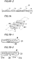
- Figs. 7A, 7B-1, 7B-2 , 7B-3, 7B-4, 7C-1 and 7C-2 illustrate an example using a synthetic resin plate as the strip-shaped member that is the soft member.
- a representative example of the synthetic resin material includes polyester elastomer.
- soft polyurethane resin, silicone elastomer, rubber (synthetic and natural) or the like may be used as a proper material.
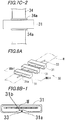
- Figs. 8A, 8B-1 , 8B-2, and 8B-3 illustrate examples using various metal wires, synthetic resin wire, and synthetic fiber wire as well as steel stranded wire having both flexibility and rigidity, as the line-shaped member that is the soft member 32.
- the slide guide illustrated in Fig. 6A is configured such that the square column member 31 (hereinafter, this member will be denoted by reference numeral 31) made of a hard resin material as the hard member is directly attached to a strip-shaped cloth 32 (hereinafter, this will be denoted by reference numeral 32) made of the same material as the base fabric for airbag or the tether as the soft member.
- a strip-shaped cloth 32 As means for attaching each square column member 31 to the strip-shaped cloth 32 in a longitudinal direction thereof while maintaining a predetermined interval therebetween, bonding, welding (fusion) using the thermoplasticity of the hard resin material or the like are possible.
- FIG. 6B-1 is a front view illustrating the slide guide 30 of Fig. 6A
- Fig. 6B-2 is a side view illustrating the slide guide 30 of Fig. 6A
- the cloth 32 may be directly used as the soft member for the tether 23 or the bag body 24 surrounding the airbag 20. In that case, as compared to the cloth of a narrow width illustrated in Fig. 6A , it is difficult to attach the square column members 31 linearly in a row, but positioning may be facilitated by preparing a simple guide ruler.
- Figs. 7A, 7B-1, 7B-2 , 7B-3, 7B-4, 7C-1 and 7C-2 illustrate a structural example where the square column members 31 made of the hard resin material as a webbing sliding part disclosed in Patent Literature 2 and a base member 34 connecting the square column members 31 to be spaced apart from each other at a predetermined interval and made of the soft resin material are integrally formed, or the slide guide 30 manufactured by fitting is further improved.
- Fig. 7A is an example where the square column members 31 made of the hard resin material and the base member 34 connecting the square column members 31 to each other and made of the soft resin material are formed in two-color molding, thus manufacturing the slide guide 30. As illustrated in Fig.
- the hard resin material and the soft resin material are thermally fused to be simultaneously molded (two-color molding).
- This manufacturing method may achieve a reduction in multiple steps such as mold setting, in addition to increasing bonding strength between the hard resin material and the soft resin material.
- the base member 34 is formed to be narrower than the square column member 31, so that it is possible to obtain effects of reducing the entire weight of the slide guide 30, improving flexibility, and reducing manufacturing cost.
- Fig. 7B-2 illustrates an example where the hard resin material is connected with the soft resin material by a mechanical coupling means.
- a base-member receiving recess 31d and a connecting dowel 31e are integrally formed on a bottom side of the square column member 31, and a dowel fastening hole is formed at a predetermined position of the base member 34. Further, it is possible to easily position the square column member 31 on the base member 34 by fitting the connecting dowel 31e into the dowel fastening hole.
- a front end of the dowel 31e protruding from a lower surface of the base member 34 is thermally melted and crushed to be integrated with the base member 34 via a caulking structure, thus allowing the square column member 31 to be reliably secured to a predetermined position of the base member 34.
- Figs. 7B-3 and 7B-4 illustrate a connection example where a base-member receiving pocket 31f is integrally formed on an external lower surface of the square column member 31, and the base member 34 is received in the base-member receiving pocket 31f to be retained.
- the base-member receiving pocket 31f includes a recess corresponding to the width and thickness of the base member 34.
- the base member 34 may be slidably inserted from the slit 31g of the base-member receiving pocket 31f into the pocket.
- a locking claw 31h is formed on an end of the slit 31g of the base-member receiving pocket 31f illustrated in Fig. 7B-4 . Therefore, this is higher in performance of retaining the base member 34 than the base-member receiving pocket 31f of Fig. 7B-3 .
- the positioning stopper 34a is formed at every position of the base member 34 for fixing the square column member 31.
- the positioning stopper 34a is made by increasing a width of a portion of the base member 34 or increasing a plate thickness. The positioning stopper 34a allows the attached position of the square column member 31 to be easily confirmed, and enhances the efficiency of work.
- Fig. 8A illustrates an embodiment using a line-shaped member as the soft member.
- the slide guide 30 of this embodiment is configured such that an insertion hole 31a is formed in the bottom side of the square column member 31 as the hard member, one wire 33 is used as the line-shaped member, and multiple square column members 31 are arranged at predetermined positions on the wire 33 extending along the airbag 20.
- the connecting structure of attaching the square column member 31 to the wire 33 may adopt the slide guide 30 formed as illustrated in Fig. 8B-1 : when the square column member 31 having a wire attachment region 31b is formed inside the bottom side of the square column member 31, the wire 33 may be integrally embedded in the wire attachment region 31b.
- the slide guide 30 may be manufactured in a single molding step.
- the square column member 31 is molded such that the insertion hole 31a which is larger in diameter than the wire is previously formed in the wire attachment region 31 b, the wire 33 passes through the insertion hole 31a in a next step, and consequently the square column members 31 may be fixedly produced at a predetermined interval in a predetermined range of the wire 33. It is preferable to form a slit 31c communicating with the wire insertion hole 31a in an outer surface of the wire attachment region 31 b, as means for simply attaching the square column member 31 to the wire 33.
- the wire 33 is accommodated in the wire insertion hole 31a through the slit 31c.
- the wire 33 basically uses a steel stranded wire 33 of a small diameter as the line-shaped member, but a resin-coated steel stranded wire 33 may be preferably used to enhance durability.
- a carbon-fiber wire 33 may be used.
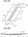
- Figs. 9 , 10A and 10B illustrate modifications of the slide guide 30 illustrated in Fig. 6 .
- the drawings illustrate a connection example where the strip-shaped cloth as the soft member illustrated in Fig. 6 is omitted and the tether 23 for retaining a shape when the airbag is inflated is directly used as the soft member. That is, since the tether 23 performs the function of the low rigidity region, the low rigidity member, such as the cloth as the strip-shaped member or the wire 33 as the line-shaped member, may be omitted, and the weight of parts and manufacturing cost thereof may be reduced.
- the following configuration is employed as illustrated in Fig. 10A (having the substantially same configuration as Fig. 3 ): the square column members 31 as the hard member are aligned on and bonded to the surface of the tether 23 which is used to control the inflating shape of the airbag 20, at a predetermined interval.
- Figs. 11A and 11B illustrate a modification of the slide guide 30 illustrated in Fig. 6 .
- the drawings illustrate a connection example where the strip-shaped cloth as the soft member illustrated in Fig. 6 is omitted and the bag body 24 of the airbag for retaining a shape when the airbag is inflated is directly used as the soft member.
- the end 23a of the tether 23 is sewn onto two spots of an upper surface of the airbag body 24 in a state of being illustrated in the drawing, and a central portion 23b of the tether 23 is sewn onto one spot of a lower surface of the airbag body 24, thus allowing the tether 23 to be placed in the bag body 24.
- the airbag body 24 itself may be the soft member.
- a simple guide ruler or the like it is preferable to use a simple guide ruler or the like, in order to arrange and assemble the hard members, such as the square column members 31, on the tether 23 and the bag body 24 linearly at a predetermined interval in a row.
Abstract
Description
- The present invention relates to a vehicle occupant restraint device, and more particularly, to a vehicle occupant restraint device that detects the collision of a vehicle so as to be effective in restraining an occupant by causing an airbag which is folded inside a seat belt to be inflated from the chest to the shoulder.
- As a vehicle occupant restraint device for protecting an occupant from two types of accidents such as a frontal collision and a lateral collision with one product, there has been developed an air belt device in which an airbag accommodated in a shoulder belt of a seat belt is inflated around a shoulder top from a chest in the event of a vehicle collision, thus restraining an occupant.
- This air belt device is operated such that an airbag is inflated along a shoulder belt fastened to an occupant in a substantially spindle shape, and the airbag in the belt is directly inflated in the event of the frontal collision, thus increasing a contact area with an occupant's chest, distributing and cushioning impacts applied to the chest. In the event of the lateral collision, an inflated portion of the airbag restrains a region extending from a shoulder top to a temporal region of an occupant, and controls a lateral movement amount of a head, thus preventing a secondary collision due to a side window or an interior structure of a vehicle.
- When this air belt device is operated by one retractor, it is necessary to pull out and take up the shoulder belt accommodating the air belt and a lap belt interposing a tongue plate therebetween. Particularly when webbing is pulled out from the retractor, the air belt portion needs to smoothly slide against the webbing such that the air belt portion (a portion of the shoulder belt) having a tongue in which the tongue plate and a gas supply hole are formed in an end thereof is provided at a proper position in a region from the chest to the shoulder while a predetermined amount of lap belt portion is pulled out.
- In
Patent Literature 1, there is disclosed a seat belt device having a flat tube made of a synthetic resin material and interposed between an airbag body and webbing. InPatent Literature 1, there are disclosed various kinds of tubes that are variously adjusted in rigidity (longitudinal and width directions of the tube) so as to ensure follow-up properties and flexibility when the webbing is pulled out while reducing the sliding resistance of the webbing that has been inserted into and passed through the flat tube. InPatent Literature 1,Fig. 4 illustrates a section of the device when the tube is integrally coupled with the airbag body. The airbag is inflated from the accommodated state ofFig. 4 in the event of a collision, between an occupant restrained by the seat belt and an interior structure of the vehicle. Therefore, a secondary collision between an occupant and the interior structure of the vehicle, such as a steering wheel or a dashboard, is prevented. - An applicant has proposed a vehicle occupant restraint device that overcomes the problems of the seat belt device disclosed in
Patent Literature 1, and adopts a slide guide having sufficient rigidity by combining a high rigidity region and a low rigidity region to webbing, thus allowing the webbing to be smoothly pulled out and mounted while a seat belt is fit for an occupant's body type when he or she fastens the seat belt (Patent Literature 2). -
- [Patent Literature 1]:
JP-A-2009-29355 - [Patent Literature 2]:
WO/2013/105639 - The seat belt device described in
Patent Literature 1 is disposed with various openings or notches in surfaces of the above-described various flat tubes so as to reduce rigidity in two directions, namely, a longitudinal direction and a width direction, so that the rigidity of the tube in the width direction is easily reduced. Therefore, this seat belt device is problematic in that, when an occupant holds an air belt portion and pulls the air belt out from a retractor so as to fasten the seat belt, the tube is deformed to cause the webbing to be rolled up, or is pushed in a thickness direction to come into contact with the tube and thereby fit the webbing therebetween, thus consequently increasing sliding resistance when the seat belt is pulled out. - Further, this seat belt device is operated such that the seat belt directly restrains an occupant's chest, and an inflated airbag independently restrains the occupant from being moved forwards. Therefore, until the forward movement of the occupant is restrained by the airbag, the restraint of his or her chest by the seat belt is likely to increase more than necessary.
- The invention disclosed in
Patent Literature 2 solves the problems occurring inPatent Literature 1. However, the invention disclosed inPatent Literature 2 is configured such that a region through which the webbing is inserted and passes desirably includes a high rigidity region, because sliding resistance of resin used for the low rigidity region among the slide guide having both the high and low rigidity regions increases. Further, it is necessary to ensure the strength of a coupling region between the high and low rigidity regions and improve durability. In addition, it is preferable to reduce the weight of members and enhance the assemblability of parts, in order to guarantee comfortability when the air belt device is fastened or to reduce the manufacturing cost of the air belt device. - Therefore, an object of the present invention is to solve the problems occurring in the related art, and is to provide a vehicle occupant restraint device, including a slide guide which has high rigidity in a width direction and a thickness direction of webbing, has low rigidity in a longitudinal direction thereof, and is manufactured in light weight and at low cost, thus allowing an air belt device to be smoothly moved along the webbing, enabling the air belt device to be properly fastened to an occupant's chest, and allowing his or her chest to be restrained without being locally compressed when the airbag is inflated.
- In order to achieve the above object, the present invention is characterized by being provided with a vehicle occupant restraint device including an airbag that is provided in a shoulder belt position of a seat belt to be capable of inflating upon receiving a predetermined actuating signal, the seat belt being wound by a single winding device, wherein the airbag is folded to surround a slide guide including a high rigidity region and a low rigidity region, the high rigidity region having seat-belt passing portions arranged at predetermined intervals in an insertion direction of the seat belt, the low rigidity region supporting the high rigidity region, and the airbag slides along the seat belt through the slide guide when the seat belt is pulled out.
- It is preferable that the high rigidity region is a cylindrical member that is made of a hard member and has seat-belt passage openings arranged at a predetermined interval along a soft member as the low rigidity region extending in a longitudinal direction of the airbag.
- It is preferable that the soft member is a strip-shaped cloth member, and is connected to an outer surface of the hard member by bonding, welding or sewing.
- It is preferable that the soft member is a line-shaped member, and is connected to the hard member in a line-shaped member attachment region formed in a portion of the hard member.
- It is preferable that wherein the soft member is a tether which restricts inflation of the airbag, or an airbag body.
- It is preferable that the high rigidity region of the slide guide is a molded body made of a hard resin material, and the low rigidity region thereof is a molded body made of a soft resin material.
- It is preferable that the slide guide is a molded product obtained by two-color molding of the hard resin material and the soft resin material.
- It is preferable that the molded product of the hard resin material of the slide guide and the molded product of the soft resin material thereof are connected to each other by mechanical connecting means.
- It is preferable that the mechanical connecting means is either of a caulking structure or a fitting structure.
- According to the present invention, it is possible to manufacture the slide guide, in light weight and at low cost, which allows an air belt portion to smoothly slide along a shoulder belt upon pulling out webbing when an occupant wears a seat belt, and it is possible to sufficiently ensure comfortability when the seat belt is fastened due to the performance of a product, whereby it is possible to fasten the air belt device at a proper position.
-
-
Fig. 1 is a perspective view illustrating a configuration example of vehicular equipment into which a vehicle occupant restraint device of the present invention is incorporated. -
Fig. 2 is a view illustrating a schematic configuration of the vehicle occupant restraint device ofFig. 1 . -
Fig. 3 is a schematic view illustrating an internal configuration of the vehicle occupant restraint device ofFig. 2 . -
Fig. 4 is a partially enlarged sectional view illustrating an example of a section of the vehicle occupant restraint device according to the present invention. -
Fig. 5A is a partially enlarged view illustrating a relationship between an inflated state of the vehicle occupant restraint device ofFig. 4 and an occupant. -
Fig. 5B is a partially enlarged view illustrating a relationship between an inflated state of the vehicle occupant restraint device ofFig. 4 and the occupant. -
Fig. 6A is a partially enlarged perspective view illustrating an embodiment of a slide guide incorporated into the vehicle occupant restraint device. -
Fig. 6B-1 is a schematic front view illustrating the slide guide ofFig. 6A . -
Fig. 6B-2 is a schematic side view illustrating the slide guide ofFig. 6A . -
Fig. 7A is a partially enlarged perspective view illustrating another embodiment of the slide guide. -
Fig. 7B-1 is a sectional view of the slide guide ofFig. 7A . -
Fig. 7B-2 is a sectional view illustrating another example of the slide guide ofFig. 7A . -
Fig. 7B-3 is a sectional view illustrating another example of the slide guide ofFig. 7A . -
Fig. 7B-4 is a sectional view illustrating another example of the slide guide ofFig. 7A . -
Fig. 7C-1 is a top view illustrating a positioning stopper of the slide guide ofFig. 7A . -
Fig. 7C-2 is a top view illustrating the positioning stopper of the slide guide ofFig. 7A . -
Fig. 8A is a partially enlarged perspective view illustrating another embodiment of the slide guide. -
Fig. 8B-1 is a sectional view illustrating the slide guide ofFig. 8A . -
Fig. 8B-2 is a sectional view illustrating another example of the slide guide ofFig. 8A . -
Fig. 8B-3 is a sectional view illustrating another example of the slide guide ofFig. 8A . -
Fig. 9 is a partially enlarged perspective view illustrating another embodiment of the slide guide. -
Fig. 10A is a partially enlarged perspective view illustrating another embodiment of the slide guide. -
Fig. 10B is a side sectional view of the slide guide ofFig. 10A . -
Fig. 11A is a partially enlarged perspective view illustrating another embodiment of the slide guide. -
Fig. 11B is a sectional view of the slide guide ofFig. 11A . - Hereinafter, an embodiment for carrying out a vehicle occupant restraint device of the present invention will be described with reference to the accompanying drawings.
-
Fig. 1 is a perspective view schematically illustrating a state in which anoccupant seat 1 is equipped with a vehicleoccupant restraint device 10 of the present invention (hereinafter also referred to as anair belt device 10 in the present invention). As illustrated in the drawing, aseat belt 3 pulled out from aretractor 2 is bent towards atongue 4, and is anchored at an end thereof to ananchor plate 6. Thisanchor plate 6 is fixed to a fixing part of a vehicular body through a fixing bolt 5. Further, in the following description, the term "seat belt" means a case of restraining an occupant or obtaining a restraint function, or a region (e.g. a shoulder belt, etc.) associated therewith. The term "webbing" means a woven cloth strip constituting the seat belt that is wound on the retractor and is pulled out by a predetermined pulling force. - As illustrated in
Fig. 1 , theretractor 2 is accommodated in a B pillar or a seat back 1B, and is fixed at a predetermined position. The webbing W is wound while retaining a predetermined tension at a seat side when an occupant sits initially. The webbing W is divided into ashoulder belt 3S and alap belt 3L, based on a position of thetongue 4. The webbing W forming thelap belt 3L is a portion that is wound on theretractor 2 except when in use. When an occupant sits in the seat, pulls the webbing W out from theretractor 2 and then draws thetongue 4 to abuckle 9, as illustrated inFig. 1 , the portion of thelap belt 3L is ensured. At this time, the occupant holds the webbing W located in his or her side and pulls it out from theretractor 2 while sitting in the seat. This position corresponds to theair belt 11 of theshoulder belt 3S in which theairbag 20 is folded and accommodated. An object of the present invention is to prevent the webbing W from being rolled up even if the webbing W is held when theair belt 11 is pulled out. A configuration for realizing this object will be described below with reference toFigs. 4 to 8 . - Another configuration of the
air belt device 10 illustrated inFig. 1 will be described in detail. Ashoulder anchor 7 is installed at an upper end of a right shoulder side of the seat back 1B. Theshoulder anchor 7 is usually formed on an upper portion of a B pillar or an upper end of the seat back 1B, so that a direction of theshoulder belt 3S is changed through theshoulder anchor 7 and thereby the shoulder belt is guided into theretractor 2. Meanwhile, as illustrated inFig. 2 in an extracted state, the air belt 11 (its configuration will be described later) is mounted on the webbing W forming theshoulder belt 3S. As illustrated inFigs. 1 and 2 , the end of theair belt 11 of the present invention is shaped such that thetongue 4 and thelap anchor 8 are integrated. Agas supply pipe 4a and atongue plate 4b are formed on thetongue 4 made of a synthetic resin material. Thegas supply pipe 4a is a metallic cylindrical member, and a gas supply path in thetongue 4 communicating with thegas supply pipe 4a is airtightly connected to agas inlet port 20a located at an end of abag body 24 of theairbag 20 illustrated inFig. 3 . -
Fig. 1 further illustrates thebuckle 9 intended to retain thegas supply pipe 4a and thetongue plate 4b of thetongue 4. Thisbuckle 9 is fixed to the fixing part of the vehicular body on the seat side through abracket 9a, using a fixing member such as a bolt or the like. A tongue-plate support hole 9b and a gas-supply-pipe connection hole 9a are formed in thebuckle 9, and thetongue plate 4b and thegas supply pipe 4a are simultaneously inserted into the respective holes of thebuckle 9 when thetongue 4 is fastened. A gas outlet port of an inflator G externally attached to thebuckle 9 communicates with the connection hole into which thegas supply pipe 4a is inserted. Thus, in the event of a collision or the like, if an actuating signal is sent to the inflator G, an ignition agent in the inflator G is ignited, so that gas is jetted from the gas outlet port of the inflator G, and the airbag 20 (seeFig. 3 ) is inflated, through thegas supply pipe 4a, in a substantially spindle shape along theshoulder belt 3S worn by an occupant. At this time, the airbag has a section that is flat and substantially elliptical, when viewed from line Va-Va ofFig. 1 (seeFig. 5A ). Therefore, the webbing W may properly restrain a wide range from the chest to the shoulder of an occupant (inFig. 1 , the inflated shape is shown by an imaginary line). - In this regard, the configuration of the
air belt 11 that is slidably mounted to the webbing W of theshoulder belt 3S will be described with reference toFigs. 2 and3 .Fig. 2 is an external view illustrating theair belt 11 through which the webbing W of theshoulder belt 3S is inserted and passes. Theair belt 11 illustrated in the drawing accommodates multiple slide guides (configuration will be described later) arranged in the longitudinal direction of the webbing W, as a core member, thebag body 24 is folded in three to form an elongated shape along the webbing W, from a deployed state illustrated inFig. 3 , and then the entire part is covered with anouter cover 21. Theouter cover 21 is made by sewing cloth in a cylindrical shape, and sewing yarn is cut at predetermined spots during an operation, so that a portion of theouter cover 21 is opened and theairbag 20 inflated from that portion is exposed. - An
opening guide ring 22 made of a polyurethane resin material is attached to an opening formed in each of opposite ends of theouter cover 21. Thisopening guide ring 22 is rarely deformed because of high rigidity, and the webbing W may easily slide and the sliding resistance of the webbing W is also reduced at the time of being pulled out because the shape of the flat opening is retained. - Although various shapes have been proposed for the
airbag 20 functioning as theair belt 11, a deployed state of an example of the airbag shape is illustrated inFig. 3 . Since thisairbag 20 forms a sectional shape ofFig. 4 in a folded state and anend 23a of alongitudinal tether 23 is sewn in the longitudinal direction of thebag body 24, the airbag is inflated in the shape of a section that is flat and substantially elliptical, as illustrated inFig. 5A . Thus, even if tension acting on the webbing W increases when theairbag 20 is inflated between an occupant and the webbing W and the seat belt is introduced, the occupant P is not locally tightened by the webbing W, and, as illustrated inFig. 5B , pressing force from the webbing W acts on a wide range including the chest and the waist of the occupant P, through theairbag 20 located between the occupant P and the webbing W. - As illustrated in
Fig. 3 , theairbag 20 functioning as theair belt 11 is slidably retained at a portion of theshoulder belt 3S by inserting the webbing W intoslits 25 of two spots formed in the vicinity of an end of theairbag 20 in the longitudinal direction thereof. As illustrated in the drawing, the air belt 11 (seeFig. 2 ) is shaped as follows: the webbing W is inserted into theslide guide 30 having predetermined rigidity and bending flexibility, theairbag 20 on each side of the webbing W is folded to surround theslide guide 30, thereby being covered with the mesh webbing and theouter cover 21. - To be more specific, the sectional configuration of the
air belt 11 and advantages that may be obtained, upon being inflated or restraining the occupant, due to the sectional configuration will be described with reference toFigs. 4 and5 . As illustrated inFig. 4 , theslide guide 30 includeshard members 31 as a high rigidity region and asoft member 32 as a low rigidity region. The hard members define a space to cause the webbing W to be inserted and passed therein. The soft member retains multiplehard members 31, extending in the longitudinal direction of the webbing W, at predetermined intervals, and allows the webbing W to be freely bent in the longitudinal direction. Further, theairbag 20 is attached to the occupant P side of theslide guide 30 through thesoft member 32, and is folded in an elongated manner to surround theslide guide 30 with theairbag 20 extending to each side of theslide guide 30, and then is entirely covered with theouter cover 21. Thus, theslide guide 30 is made by integrating the high rigidity region that causes the webbing W to pass therethrough with the low rigidity region that is freely bent to fit for the body type of the occupant, and then is arranged over a predetermined range of theairbag 20 in the longitudinal direction thereof, thus allowing the foldedbag body 24 to smoothly slide along the webbing W. - Since the
airbag 20 is fixed to the occupant's side of theslide guide 30 and is folded to surround theslide guide 30, in the event of a collision, as illustrated inFig. 5A , the webbing W is introduced to restrain the occupant P, and simultaneously, theairbag 20 is inflated between the webbing W and the occupant P while forming a predetermined flat shape. If an introduced amount of the webbing W increases in the state where theairbag 20 is inflated, as illustrated inFig. 5B , a contact degree to the occupant P increases as theairbag 20 is deformed, and the effect of restraining the occupant may increase. Preferably, theslide guide 30 efficiently converts the increased tension of the webbing W into a pressing force in a direction (occupant direction) shown by an outline arrow in the drawing. However, even if the tension of the webbing W is increased by the high rigidity region having sufficient rigidity, the sectional deformation of theslide guide 30 is kept small, and the pressing force is distributed over theairbag 20, so that it is possible to restrain the occupant P in a wide surface of theairbag 20. - Hereinafter, the configuration of the
slide guide 30 contributing to the slide behavior of the webbing W, a deformation behavior and the like will be described with reference toFigs. 6 to 10 . Theslide guide 30 includeshard members 31 as a high rigidity region and asoft member 32 as a low rigidity region. The hard members define a space to cause the webbing W to be inserted and passed therein. The soft member retains multiplehard members 31, extending in the longitudinal direction of the webbing W, at predetermined intervals, and allows the webbing W to be freely bent in the longitudinal direction. - The present embodiment illustrated in
Figs. 6 to 10 employs a square column member as thehard member 31. The square column member has a seat-belt passage opening, an inner dimension of which is slightly larger than a width of the webbing W, is chamfered at a corner in a flat and round shape that is about 1.5 cm in a longitudinal direction thereof, and has a predetermined rigidity. Thehard member 31 of such a shape has a high rigidity in the width direction of the webbing W, and an interval between neighboringhard members 31 in the longitudinal direction of the webbing W is set to 1 cm or less. In this embodiment, polyurethane resin is used as a resin material forming thehard member 31. In addition, as an appropriate material, polyester elastomer, polyamide resin, hard polyurethane resin, polyester resin, metal plate or the like may be used. - Embodiments illustrated in
Figs. 6 to 10 employ, as thesoft member 32, an elongated strip-shaped member and line-shaped member, the width of which is substantially equal to that of the webbing W. In order to function as a configuration of theslide guide 30, the soft member is fixed in a range in the longitudinal direction of thetether 23 illustrated inFig. 3 by bonding or sewing. According to the present embodiment, it is preferable to employ cloth having flexibility or a thin plate of synthetic resin, as the strip-shaped member constituting thesoft member 32.Figs. 6A, 6B-1 and6B-2 illustrate an example where cloth is used as the strip-shaped member that is the soft member. Where the cloth is employed as thesoft member 32, thetether 23 or a base fabric for airbag is used. Woven cloth of polyamide fiber is preferably used as a material of thetether 23 or the base fabric for airbag.Figs. 7A, 7B-1, 7B-2 ,7B-3, 7B-4, 7C-1 and7C-2 illustrate an example using a synthetic resin plate as the strip-shaped member that is the soft member. A representative example of the synthetic resin material includes polyester elastomer. In addition, soft polyurethane resin, silicone elastomer, rubber (synthetic and natural) or the like may be used as a proper material.Figs. 8A, 8B-1 ,8B-2, and 8B-3 illustrate examples using various metal wires, synthetic resin wire, and synthetic fiber wire as well as steel stranded wire having both flexibility and rigidity, as the line-shaped member that is thesoft member 32. - Hereinafter, the configuration of respective members will be described in detail with reference to the accompanying drawings (
Figs. 6 to 10 ). - The slide guide illustrated in
Fig. 6A is configured such that the square column member 31 (hereinafter, this member will be denoted by reference numeral 31) made of a hard resin material as the hard member is directly attached to a strip-shaped cloth 32 (hereinafter, this will be denoted by reference numeral 32) made of the same material as the base fabric for airbag or the tether as the soft member. As means for attaching eachsquare column member 31 to the strip-shapedcloth 32 in a longitudinal direction thereof while maintaining a predetermined interval therebetween, bonding, welding (fusion) using the thermoplasticity of the hard resin material or the like are possible. Such an attaching structure is advantageous in that individualsquare column members 31 have only to be aligned on one piece ofelongated cloth 32 for the purpose of integration, so that it is possible to manufacture a small number of light-weight slide guide 30.Fig. 6B-1 is a front view illustrating theslide guide 30 ofFig. 6A , andFig. 6B-2 is a side view illustrating theslide guide 30 ofFig. 6A . As illustrated in the drawings, since neighboring hard members are continuously arranged by cloth, it is possible to provide theslide guide 30 having very high flexibility. As will be described later with reference toFig. 9 , thecloth 32 may be directly used as the soft member for thetether 23 or thebag body 24 surrounding theairbag 20. In that case, as compared to the cloth of a narrow width illustrated inFig. 6A , it is difficult to attach thesquare column members 31 linearly in a row, but positioning may be facilitated by preparing a simple guide ruler. -
Figs. 7A, 7B-1, 7B-2 ,7B-3, 7B-4, 7C-1 and7C-2 illustrate a structural example where thesquare column members 31 made of the hard resin material as a webbing sliding part disclosed inPatent Literature 2 and abase member 34 connecting thesquare column members 31 to be spaced apart from each other at a predetermined interval and made of the soft resin material are integrally formed, or theslide guide 30 manufactured by fitting is further improved.Fig. 7A is an example where thesquare column members 31 made of the hard resin material and thebase member 34 connecting thesquare column members 31 to each other and made of the soft resin material are formed in two-color molding, thus manufacturing theslide guide 30. As illustrated inFig. 7B-1 , the hard resin material and the soft resin material are thermally fused to be simultaneously molded (two-color molding). This manufacturing method may achieve a reduction in multiple steps such as mold setting, in addition to increasing bonding strength between the hard resin material and the soft resin material. Further, thebase member 34 is formed to be narrower than thesquare column member 31, so that it is possible to obtain effects of reducing the entire weight of theslide guide 30, improving flexibility, and reducing manufacturing cost. -
Fig. 7B-2 illustrates an example where the hard resin material is connected with the soft resin material by a mechanical coupling means. In this connection example, a base-member receiving recess 31d and a connectingdowel 31e are integrally formed on a bottom side of thesquare column member 31, and a dowel fastening hole is formed at a predetermined position of thebase member 34. Further, it is possible to easily position thesquare column member 31 on thebase member 34 by fitting the connectingdowel 31e into the dowel fastening hole. A front end of thedowel 31e protruding from a lower surface of thebase member 34 is thermally melted and crushed to be integrated with thebase member 34 via a caulking structure, thus allowing thesquare column member 31 to be reliably secured to a predetermined position of thebase member 34. -
Figs. 7B-3 and 7B-4 illustrate a connection example where a base-member receiving pocket 31f is integrally formed on an external lower surface of thesquare column member 31, and thebase member 34 is received in the base-member receiving pocket 31f to be retained. The base-member receiving pocket 31f includes a recess corresponding to the width and thickness of thebase member 34. Thebase member 34 may be slidably inserted from theslit 31g of the base-member receiving pocket 31f into the pocket. A lockingclaw 31h is formed on an end of theslit 31g of the base-member receiving pocket 31f illustrated inFig. 7B-4 . Therefore, this is higher in performance of retaining thebase member 34 than the base-member receiving pocket 31f ofFig. 7B-3 . As illustrated inFigs. 7C-1 and7C-2 , thepositioning stopper 34a is formed at every position of thebase member 34 for fixing thesquare column member 31. Thepositioning stopper 34a is made by increasing a width of a portion of thebase member 34 or increasing a plate thickness. Thepositioning stopper 34a allows the attached position of thesquare column member 31 to be easily confirmed, and enhances the efficiency of work. -
Fig. 8A illustrates an embodiment using a line-shaped member as the soft member. The slide guide 30 of this embodiment is configured such that aninsertion hole 31a is formed in the bottom side of thesquare column member 31 as the hard member, onewire 33 is used as the line-shaped member, and multiplesquare column members 31 are arranged at predetermined positions on thewire 33 extending along theairbag 20. The connecting structure of attaching thesquare column member 31 to thewire 33 may adopt theslide guide 30 formed as illustrated inFig. 8B-1 : when thesquare column member 31 having awire attachment region 31b is formed inside the bottom side of thesquare column member 31, thewire 33 may be integrally embedded in thewire attachment region 31b. In this case, since thewire 33 is integrated into thewire attachment region 31b of thesquare column member 31, theslide guide 30 may be manufactured in a single molding step. According to another structural example, as illustrated inFig. 8B-2 , thesquare column member 31 is molded such that theinsertion hole 31a which is larger in diameter than the wire is previously formed in thewire attachment region 31 b, thewire 33 passes through theinsertion hole 31a in a next step, and consequently thesquare column members 31 may be fixedly produced at a predetermined interval in a predetermined range of thewire 33. It is preferable to form aslit 31c communicating with thewire insertion hole 31a in an outer surface of thewire attachment region 31 b, as means for simply attaching thesquare column member 31 to thewire 33. Thewire 33 is accommodated in thewire insertion hole 31a through theslit 31c. Thewire 33 basically uses a steel strandedwire 33 of a small diameter as the line-shaped member, but a resin-coated steel strandedwire 33 may be preferably used to enhance durability. In order to reduce the weight of theslide guide 30, a carbon-fiber wire 33 may be used. In the manufacture examples ofFigs. 8B-2 and 8B-3 , it is preferable to fix eachsquare column member 31 to thewire 33 by filling a gap between thewire insertion hole 31a and thewire 33 with an adhesive. -
Figs. 9 ,10A and 10B illustrate modifications of theslide guide 30 illustrated inFig. 6 . The drawings illustrate a connection example where the strip-shaped cloth as the soft member illustrated inFig. 6 is omitted and thetether 23 for retaining a shape when the airbag is inflated is directly used as the soft member. That is, since thetether 23 performs the function of the low rigidity region, the low rigidity member, such as the cloth as the strip-shaped member or thewire 33 as the line-shaped member, may be omitted, and the weight of parts and manufacturing cost thereof may be reduced. As anactual slide guide 30, the following configuration is employed as illustrated inFig. 10A (having the substantially same configuration asFig. 3 ): thesquare column members 31 as the hard member are aligned on and bonded to the surface of thetether 23 which is used to control the inflating shape of theairbag 20, at a predetermined interval. -
Figs. 11A and 11B illustrate a modification of theslide guide 30 illustrated inFig. 6 . The drawings illustrate a connection example where the strip-shaped cloth as the soft member illustrated inFig. 6 is omitted and thebag body 24 of the airbag for retaining a shape when the airbag is inflated is directly used as the soft member. As illustrated inFig. 11B , in this modification, theend 23a of thetether 23 is sewn onto two spots of an upper surface of theairbag body 24 in a state of being illustrated in the drawing, and acentral portion 23b of thetether 23 is sewn onto one spot of a lower surface of theairbag body 24, thus allowing thetether 23 to be placed in thebag body 24. Therefore, theairbag body 24 itself may be the soft member. In the modifications illustrated inFigs. 9 ,10A ,10B ,11A and 11B , it is preferable to use a simple guide ruler or the like, in order to arrange and assemble the hard members, such as thesquare column members 31, on thetether 23 and thebag body 24 linearly at a predetermined interval in a row. - Various embodiments and modifications of the present invention may be made without departing from the broad spirit and scope of the present invention. Further, the above-described embodiments are intended to describe the invention but are not intended to limit the scope of the present invention. That is, the scope of the present invention is defined not by the embodiments but by the accompanying claims. Various changes made within the scope of the claims and equivalence thereof will be considered to be within the scope of this invention.
- This application claims priority from Japanese Patent Application No.
2014-122938 filed on June 14, 2014 2014-122938 -
- 1:
- occupant seat
- 2:
- retractor
- 3:
- seat belt
- 3S:
- shoulder belt
- 3L:
- lap belt
- 4:
- tongue
- 9:
- buckle
- 10:
- vehicle occupant restraint device (air belt device)
- 11:
- air belt
- 20:
- airbag
- 23:
- tether
- 24:
- bag body
- 30:
- slide guide
- 31:
- hard member
- 32:
- soft member
Claims (10)
- A vehicle occupant restraint device comprising:an airbag that is provided in a shoulder belt position of a seat belt to be capable of inflating upon receiving a predetermined actuating signal, the seat belt being wound by a single winding device,characterized in that the airbag is folded to surround a slide guide including a high rigidity region and a low rigidity region, the high rigidity region having seat-belt passing portions arranged at predetermined intervals in an insertion direction of the seat belt, the low rigidity region supporting the high rigidity region, and the airbag slides along the seat belt through the slide guide when the seat belt is pulled out.
- The vehicle occupant restraint device of claim 1, wherein the high rigidity region is a cylindrical member that is made of a hard member and has seat-belt passage openings arranged at a predetermined interval along a soft member as the low rigidity region extending in a longitudinal direction of the airbag.
- The vehicle occupant restraint device of claim 2, wherein the soft member is a strip-shaped cloth member, and is connected to an outer surface of the hard member by bonding, welding or sewing.
- The vehicle occupant restraint device of claim 2, wherein the soft member is a line-shaped member, and is connected to the hard member in a line-shaped member attachment region formed in a portion of the hard member.
- The vehicle occupant restraint device of claim 2, wherein the soft member is a tether which restricts inflation of the airbag.
- The vehicle occupant restraint device of claim 2, wherein the soft member is an airbag body.
- The vehicle occupant restraint device of claim 1, wherein the high rigidity region of the slide guide is a molded body made of a hard resin material, and the low rigidity region thereof is a molded body made of a soft resin material.
- The vehicle occupant restraint device of claim 7, wherein the slide guide is a molded product obtained by two-color molding of the hard resin material and the soft resin material.
- The vehicle occupant restraint device of claim 7, wherein the molded product of the hard resin material of the slide guide and the molded product of the soft resin material thereof are connected to each other by mechanical connecting means.
- The vehicle occupant restraint device of claim 9, wherein the mechanical connecting means is either of a caulking structure or a fitting structure.
Applications Claiming Priority (2)
| Application Number | Priority Date | Filing Date | Title |
|---|---|---|---|
| JP2014122938A JP2016002822A (en) | 2014-06-14 | 2014-06-14 | Occupant restraint device |
| PCT/JP2015/058728 WO2015190152A1 (en) | 2014-06-14 | 2015-03-23 | Vehicle occupant restraint device |
Publications (3)
| Publication Number | Publication Date |
|---|---|
| EP3156288A1 true EP3156288A1 (en) | 2017-04-19 |
| EP3156288A4 EP3156288A4 (en) | 2018-01-17 |
| EP3156288B1 EP3156288B1 (en) | 2019-02-20 |
Family
ID=54833261
Family Applications (1)
| Application Number | Title | Priority Date | Filing Date |
|---|---|---|---|
| EP15805814.9A Not-in-force EP3156288B1 (en) | 2014-06-14 | 2015-03-23 | Vehicle occupant restraint device |
Country Status (4)
| Country | Link |
|---|---|
| US (1) | US9963098B2 (en) |
| EP (1) | EP3156288B1 (en) |
| JP (1) | JP2016002822A (en) |
| WO (1) | WO2015190152A1 (en) |
Families Citing this family (8)
| Publication number | Priority date | Publication date | Assignee | Title |
|---|---|---|---|---|
| US10183646B2 (en) * | 2016-05-13 | 2019-01-22 | Joyson Safety Systems Japan K.K. | Occupant restraining apparatus |
| WO2018093852A2 (en) * | 2016-11-18 | 2018-05-24 | Indiana Mills & Manufacturing, Inc. | Dynamic tensioner and load reducing device |
| KR102394829B1 (en) * | 2017-04-18 | 2022-05-06 | 현대자동차주식회사 | Airbelt apparatus for vehicle |
| JP6913508B2 (en) * | 2017-05-22 | 2021-08-04 | Joyson Safety Systems Japan株式会社 | Airbag device and seat belt device |
| JP2019051859A (en) * | 2017-09-15 | 2019-04-04 | Joyson Safety Systems Japan株式会社 | Air bag and seat belt device |
| JP2019064537A (en) * | 2017-10-04 | 2019-04-25 | Joyson Safety Systems Japan株式会社 | Air bag and air bag device |
| GB2579667B (en) * | 2018-12-12 | 2021-01-13 | Ford Global Tech Llc | An airbag |
| US10889257B2 (en) * | 2019-02-27 | 2021-01-12 | Ford Global Technologies, Llc | Vehicle seat assembly |
Family Cites Families (18)
| Publication number | Priority date | Publication date | Assignee | Title |
|---|---|---|---|---|
| US5282648A (en) * | 1992-06-01 | 1994-02-01 | Simula Inc. | Inflatable body and head restraint system |
| JP3500926B2 (en) * | 1997-09-02 | 2004-02-23 | タカタ株式会社 | Air belt device |
| DE19804365C2 (en) * | 1998-02-04 | 2000-06-08 | Hs Tech & Design | Three-point seat belt |
| JP3521769B2 (en) | 1998-11-09 | 2004-04-19 | トヨタ自動車株式会社 | Head protection airbag device |
| JP4331853B2 (en) | 2000-03-23 | 2009-09-16 | 本田技研工業株式会社 | Air belt device |
| JP2004058698A (en) | 2002-07-24 | 2004-02-26 | Autoliv Japan Ltd | Inflatable seat belt device |
| DE102004007768A1 (en) * | 2004-02-18 | 2006-06-01 | Volkswagen Ag | Passenger e.g. child, support device for vehicle seat, has airbag which blows out during crash conditioned airbag activation under shifting of impact section in passenger direction via outlet, and is designed as additional support unit |
| JP4835312B2 (en) * | 2005-10-07 | 2011-12-14 | タカタ株式会社 | Connection body of air belt and anchor and air belt device |
| JP4923524B2 (en) * | 2005-11-11 | 2012-04-25 | 日産自動車株式会社 | Occupant protection device and occupant protection method during vehicle rollover |
| JP2009029355A (en) | 2007-07-30 | 2009-02-12 | Nissan Motor Co Ltd | Seat belt device with air bag |
| JP2009029357A (en) * | 2007-07-30 | 2009-02-12 | Nissan Motor Co Ltd | Seat belt device with air bag |
| JP5239604B2 (en) * | 2008-08-08 | 2013-07-17 | タカタ株式会社 | Crew restraint system |
| CN103313881B (en) * | 2010-10-28 | 2016-04-20 | 关键安全体系股份有限公司 | Single retractor inflatable belt system |
| US9199599B2 (en) | 2012-01-11 | 2015-12-01 | Takata Corporation | Passenger protection device |
| EP2804788B1 (en) * | 2012-01-17 | 2017-08-23 | Helite S.a.r.l. | Protecting device for the head and the neck of an idividual |
| JP2013184559A (en) * | 2012-03-07 | 2013-09-19 | Takata Corp | Occupant protection device |
| JP5914167B2 (en) | 2012-05-25 | 2016-05-11 | タカタ株式会社 | Crew protection device |
| KR20140071011A (en) * | 2012-12-03 | 2014-06-11 | 현대자동차주식회사 | Air bag cushion for seat belt |
-
2014
- 2014-06-14 JP JP2014122938A patent/JP2016002822A/en active Pending
-
2015
- 2015-03-23 EP EP15805814.9A patent/EP3156288B1/en not_active Not-in-force
- 2015-03-23 US US15/318,230 patent/US9963098B2/en not_active Expired - Fee Related
- 2015-03-23 WO PCT/JP2015/058728 patent/WO2015190152A1/en active Application Filing
Also Published As
| Publication number | Publication date |
|---|---|
| US9963098B2 (en) | 2018-05-08 |
| EP3156288B1 (en) | 2019-02-20 |
| JP2016002822A (en) | 2016-01-12 |
| WO2015190152A1 (en) | 2015-12-17 |
| US20170106828A1 (en) | 2017-04-20 |
| EP3156288A4 (en) | 2018-01-17 |
Similar Documents
| Publication | Publication Date | Title |
|---|---|---|
| EP3156288B1 (en) | Vehicle occupant restraint device | |
| US7845734B2 (en) | Vehicle seatbelt | |
| US9393926B2 (en) | Folding patterns of an inflatable seat belt | |
| JP4621281B2 (en) | Seat belt pretensioner | |
| KR101806590B1 (en) | Single retractor inflatable belt system | |
| US9434339B2 (en) | Inflatable seat belt with a tethered gas delivery fill tube | |
| EP1987991B1 (en) | Air belt device for vehicle | |
| US9988012B2 (en) | Seat belt system | |
| US9199599B2 (en) | Passenger protection device | |
| JP2006088899A (en) | Occupant crash protection device | |
| US7922195B2 (en) | Vehicle occupant restraint system | |
| JP2010105544A (en) | Occupant restraint device | |
| CN112789198B (en) | Seat belt device for motor vehicle | |
| KR101133593B1 (en) | Structure of prevent moving seat belt webbing for automobile | |
| US11014520B2 (en) | Airbag apparatus and seatbelt apparatus | |
| JP5871475B2 (en) | Crew protection device | |
| CN108725377A (en) | Air belt apparatus for motor for vehicle | |
| JP6825417B2 (en) | Vehicle seatbelt guide structure | |
| JP5495691B2 (en) | Vehicle seat device | |
| KR100371708B1 (en) | Device for fixing a tongue of three poing type seat belt to a roof panel | |
| JP2015048016A (en) | Seat belt device | |
| JP2010069902A (en) | Seat belt apparatus |
Legal Events
| Date | Code | Title | Description |
|---|---|---|---|
| STAA | Information on the status of an ep patent application or granted ep patent |
Free format text: STATUS: THE INTERNATIONAL PUBLICATION HAS BEEN MADE |
|
| PUAI | Public reference made under article 153(3) epc to a published international application that has entered the european phase |
Free format text: ORIGINAL CODE: 0009012 |
|
| STAA | Information on the status of an ep patent application or granted ep patent |
Free format text: STATUS: REQUEST FOR EXAMINATION WAS MADE |
|
| 17P | Request for examination filed |
Effective date: 20161213 |
|
| AK | Designated contracting states |
Kind code of ref document: A1 Designated state(s): AL AT BE BG CH CY CZ DE DK EE ES FI FR GB GR HR HU IE IS IT LI LT LU LV MC MK MT NL NO PL PT RO RS SE SI SK SM TR |
|
| AX | Request for extension of the european patent |
Extension state: BA ME |
|
| DAV | Request for validation of the european patent (deleted) | ||
| DAX | Request for extension of the european patent (deleted) | ||
| A4 | Supplementary search report drawn up and despatched |
Effective date: 20171219 |
|
| RIC1 | Information provided on ipc code assigned before grant |
Ipc: B60R 21/237 20060101ALI20171211BHEP Ipc: B60R 21/18 20060101AFI20171211BHEP Ipc: B60R 21/2338 20110101ALI20171211BHEP Ipc: B60R 22/14 20060101ALI20171211BHEP Ipc: B60R 21/235 20060101ALI20171211BHEP |
|
| RAP1 | Party data changed (applicant data changed or rights of an application transferred) |
Owner name: JOYSON SAFETY SYSTEMS JAPAN K.K. |
|
| REG | Reference to a national code |
Ref country code: DE Ref legal event code: R079 Ref document number: 602015025004 Country of ref document: DE Free format text: PREVIOUS MAIN CLASS: B60R0021180000 Ipc: B60R0022140000 |
|
| RIC1 | Information provided on ipc code assigned before grant |
Ipc: B60R 21/2338 20110101ALI20180719BHEP Ipc: B60R 21/237 20060101ALI20180719BHEP Ipc: B60R 21/235 20060101ALI20180719BHEP Ipc: B60R 22/18 20060101ALI20180719BHEP Ipc: B60R 21/18 20060101ALI20180719BHEP Ipc: B60R 22/14 20060101AFI20180719BHEP |
|
| GRAP | Despatch of communication of intention to grant a patent |
Free format text: ORIGINAL CODE: EPIDOSNIGR1 |
|
| STAA | Information on the status of an ep patent application or granted ep patent |
Free format text: STATUS: GRANT OF PATENT IS INTENDED |
|
| INTG | Intention to grant announced |
Effective date: 20180907 |
|
| GRAS | Grant fee paid |
Free format text: ORIGINAL CODE: EPIDOSNIGR3 |
|
| GRAA | (expected) grant |
Free format text: ORIGINAL CODE: 0009210 |
|
| STAA | Information on the status of an ep patent application or granted ep patent |
Free format text: STATUS: THE PATENT HAS BEEN GRANTED |
|
| AK | Designated contracting states |
Kind code of ref document: B1 Designated state(s): AL AT BE BG CH CY CZ DE DK EE ES FI FR GB GR HR HU IE IS IT LI LT LU LV MC MK MT NL NO PL PT RO RS SE SI SK SM TR |
|
| REG | Reference to a national code |
Ref country code: GB Ref legal event code: FG4D |
|
| REG | Reference to a national code |
Ref country code: CH Ref legal event code: EP |
|
| REG | Reference to a national code |
Ref country code: DE Ref legal event code: R096 Ref document number: 602015025004 Country of ref document: DE |
|
| REG | Reference to a national code |
Ref country code: AT Ref legal event code: REF Ref document number: 1097755 Country of ref document: AT Kind code of ref document: T Effective date: 20190315 |
|
| REG | Reference to a national code |
Ref country code: IE Ref legal event code: FG4D |
|
| REG | Reference to a national code |
Ref country code: LT Ref legal event code: MG4D |
|
| REG | Reference to a national code |
Ref country code: NL Ref legal event code: MP Effective date: 20190220 |
|
| PG25 | Lapsed in a contracting state [announced via postgrant information from national office to epo] |
Ref country code: LT Free format text: LAPSE BECAUSE OF FAILURE TO SUBMIT A TRANSLATION OF THE DESCRIPTION OR TO PAY THE FEE WITHIN THE PRESCRIBED TIME-LIMIT Effective date: 20190220 Ref country code: FI Free format text: LAPSE BECAUSE OF FAILURE TO SUBMIT A TRANSLATION OF THE DESCRIPTION OR TO PAY THE FEE WITHIN THE PRESCRIBED TIME-LIMIT Effective date: 20190220 Ref country code: NO Free format text: LAPSE BECAUSE OF FAILURE TO SUBMIT A TRANSLATION OF THE DESCRIPTION OR TO PAY THE FEE WITHIN THE PRESCRIBED TIME-LIMIT Effective date: 20190520 Ref country code: PT Free format text: LAPSE BECAUSE OF FAILURE TO SUBMIT A TRANSLATION OF THE DESCRIPTION OR TO PAY THE FEE WITHIN THE PRESCRIBED TIME-LIMIT Effective date: 20190620 Ref country code: SE Free format text: LAPSE BECAUSE OF FAILURE TO SUBMIT A TRANSLATION OF THE DESCRIPTION OR TO PAY THE FEE WITHIN THE PRESCRIBED TIME-LIMIT Effective date: 20190220 |
|
| PG25 | Lapsed in a contracting state [announced via postgrant information from national office to epo] |
Ref country code: NL Free format text: LAPSE BECAUSE OF FAILURE TO SUBMIT A TRANSLATION OF THE DESCRIPTION OR TO PAY THE FEE WITHIN THE PRESCRIBED TIME-LIMIT Effective date: 20190220 Ref country code: HR Free format text: LAPSE BECAUSE OF FAILURE TO SUBMIT A TRANSLATION OF THE DESCRIPTION OR TO PAY THE FEE WITHIN THE PRESCRIBED TIME-LIMIT Effective date: 20190220 Ref country code: RS Free format text: LAPSE BECAUSE OF FAILURE TO SUBMIT A TRANSLATION OF THE DESCRIPTION OR TO PAY THE FEE WITHIN THE PRESCRIBED TIME-LIMIT Effective date: 20190220 Ref country code: BG Free format text: LAPSE BECAUSE OF FAILURE TO SUBMIT A TRANSLATION OF THE DESCRIPTION OR TO PAY THE FEE WITHIN THE PRESCRIBED TIME-LIMIT Effective date: 20190520 Ref country code: GR Free format text: LAPSE BECAUSE OF FAILURE TO SUBMIT A TRANSLATION OF THE DESCRIPTION OR TO PAY THE FEE WITHIN THE PRESCRIBED TIME-LIMIT Effective date: 20190521 Ref country code: IS Free format text: LAPSE BECAUSE OF FAILURE TO SUBMIT A TRANSLATION OF THE DESCRIPTION OR TO PAY THE FEE WITHIN THE PRESCRIBED TIME-LIMIT Effective date: 20190620 Ref country code: LV Free format text: LAPSE BECAUSE OF FAILURE TO SUBMIT A TRANSLATION OF THE DESCRIPTION OR TO PAY THE FEE WITHIN THE PRESCRIBED TIME-LIMIT Effective date: 20190220 |
|
| REG | Reference to a national code |
Ref country code: AT Ref legal event code: MK05 Ref document number: 1097755 Country of ref document: AT Kind code of ref document: T Effective date: 20190220 |
|
| PG25 | Lapsed in a contracting state [announced via postgrant information from national office to epo] |
Ref country code: AL Free format text: LAPSE BECAUSE OF FAILURE TO SUBMIT A TRANSLATION OF THE DESCRIPTION OR TO PAY THE FEE WITHIN THE PRESCRIBED TIME-LIMIT Effective date: 20190220 Ref country code: DK Free format text: LAPSE BECAUSE OF FAILURE TO SUBMIT A TRANSLATION OF THE DESCRIPTION OR TO PAY THE FEE WITHIN THE PRESCRIBED TIME-LIMIT Effective date: 20190220 Ref country code: IT Free format text: LAPSE BECAUSE OF FAILURE TO SUBMIT A TRANSLATION OF THE DESCRIPTION OR TO PAY THE FEE WITHIN THE PRESCRIBED TIME-LIMIT Effective date: 20190220 Ref country code: SK Free format text: LAPSE BECAUSE OF FAILURE TO SUBMIT A TRANSLATION OF THE DESCRIPTION OR TO PAY THE FEE WITHIN THE PRESCRIBED TIME-LIMIT Effective date: 20190220 Ref country code: EE Free format text: LAPSE BECAUSE OF FAILURE TO SUBMIT A TRANSLATION OF THE DESCRIPTION OR TO PAY THE FEE WITHIN THE PRESCRIBED TIME-LIMIT Effective date: 20190220 Ref country code: RO Free format text: LAPSE BECAUSE OF FAILURE TO SUBMIT A TRANSLATION OF THE DESCRIPTION OR TO PAY THE FEE WITHIN THE PRESCRIBED TIME-LIMIT Effective date: 20190220 Ref country code: CZ Free format text: LAPSE BECAUSE OF FAILURE TO SUBMIT A TRANSLATION OF THE DESCRIPTION OR TO PAY THE FEE WITHIN THE PRESCRIBED TIME-LIMIT Effective date: 20190220 Ref country code: ES Free format text: LAPSE BECAUSE OF FAILURE TO SUBMIT A TRANSLATION OF THE DESCRIPTION OR TO PAY THE FEE WITHIN THE PRESCRIBED TIME-LIMIT Effective date: 20190220 |
|
| REG | Reference to a national code |
Ref country code: CH Ref legal event code: PL |
|
| REG | Reference to a national code |
Ref country code: DE Ref legal event code: R097 Ref document number: 602015025004 Country of ref document: DE |
|
| PG25 | Lapsed in a contracting state [announced via postgrant information from national office to epo] |
Ref country code: SM Free format text: LAPSE BECAUSE OF FAILURE TO SUBMIT A TRANSLATION OF THE DESCRIPTION OR TO PAY THE FEE WITHIN THE PRESCRIBED TIME-LIMIT Effective date: 20190220 Ref country code: PL Free format text: LAPSE BECAUSE OF FAILURE TO SUBMIT A TRANSLATION OF THE DESCRIPTION OR TO PAY THE FEE WITHIN THE PRESCRIBED TIME-LIMIT Effective date: 20190220 Ref country code: LU Free format text: LAPSE BECAUSE OF NON-PAYMENT OF DUE FEES Effective date: 20190323 |
|
| REG | Reference to a national code |
Ref country code: BE Ref legal event code: MM Effective date: 20190331 |
|
| PLBE | No opposition filed within time limit |
Free format text: ORIGINAL CODE: 0009261 |
|
| STAA | Information on the status of an ep patent application or granted ep patent |
Free format text: STATUS: NO OPPOSITION FILED WITHIN TIME LIMIT |
|
| PG25 | Lapsed in a contracting state [announced via postgrant information from national office to epo] |
Ref country code: MC Free format text: LAPSE BECAUSE OF FAILURE TO SUBMIT A TRANSLATION OF THE DESCRIPTION OR TO PAY THE FEE WITHIN THE PRESCRIBED TIME-LIMIT Effective date: 20190220 Ref country code: AT Free format text: LAPSE BECAUSE OF FAILURE TO SUBMIT A TRANSLATION OF THE DESCRIPTION OR TO PAY THE FEE WITHIN THE PRESCRIBED TIME-LIMIT Effective date: 20190220 |
|
| 26N | No opposition filed |
Effective date: 20191121 |
|
| GBPC | Gb: european patent ceased through non-payment of renewal fee |
Effective date: 20190520 |
|
| PG25 | Lapsed in a contracting state [announced via postgrant information from national office to epo] |
Ref country code: LI Free format text: LAPSE BECAUSE OF NON-PAYMENT OF DUE FEES Effective date: 20190331 Ref country code: IE Free format text: LAPSE BECAUSE OF NON-PAYMENT OF DUE FEES Effective date: 20190323 Ref country code: CH Free format text: LAPSE BECAUSE OF NON-PAYMENT OF DUE FEES Effective date: 20190331 |
|
| PG25 | Lapsed in a contracting state [announced via postgrant information from national office to epo] |
Ref country code: BE Free format text: LAPSE BECAUSE OF NON-PAYMENT OF DUE FEES Effective date: 20190331 Ref country code: SI Free format text: LAPSE BECAUSE OF FAILURE TO SUBMIT A TRANSLATION OF THE DESCRIPTION OR TO PAY THE FEE WITHIN THE PRESCRIBED TIME-LIMIT Effective date: 20190220 Ref country code: FR Free format text: LAPSE BECAUSE OF NON-PAYMENT OF DUE FEES Effective date: 20190420 |
|
| PG25 | Lapsed in a contracting state [announced via postgrant information from national office to epo] |
Ref country code: TR Free format text: LAPSE BECAUSE OF FAILURE TO SUBMIT A TRANSLATION OF THE DESCRIPTION OR TO PAY THE FEE WITHIN THE PRESCRIBED TIME-LIMIT Effective date: 20190220 |
|
| PG25 | Lapsed in a contracting state [announced via postgrant information from national office to epo] |
Ref country code: GB Free format text: LAPSE BECAUSE OF NON-PAYMENT OF DUE FEES Effective date: 20190520 |
|
| PG25 | Lapsed in a contracting state [announced via postgrant information from national office to epo] |
Ref country code: MT Free format text: LAPSE BECAUSE OF NON-PAYMENT OF DUE FEES Effective date: 20190323 |
|
| PG25 | Lapsed in a contracting state [announced via postgrant information from national office to epo] |
Ref country code: CY Free format text: LAPSE BECAUSE OF FAILURE TO SUBMIT A TRANSLATION OF THE DESCRIPTION OR TO PAY THE FEE WITHIN THE PRESCRIBED TIME-LIMIT Effective date: 20190220 |
|
| PGFP | Annual fee paid to national office [announced via postgrant information from national office to epo] |
Ref country code: DE Payment date: 20210319 Year of fee payment: 7 |
|
| PG25 | Lapsed in a contracting state [announced via postgrant information from national office to epo] |
Ref country code: HU Free format text: LAPSE BECAUSE OF FAILURE TO SUBMIT A TRANSLATION OF THE DESCRIPTION OR TO PAY THE FEE WITHIN THE PRESCRIBED TIME-LIMIT; INVALID AB INITIO Effective date: 20150323 |
|
| PG25 | Lapsed in a contracting state [announced via postgrant information from national office to epo] |
Ref country code: MK Free format text: LAPSE BECAUSE OF FAILURE TO SUBMIT A TRANSLATION OF THE DESCRIPTION OR TO PAY THE FEE WITHIN THE PRESCRIBED TIME-LIMIT Effective date: 20190220 |
|
| REG | Reference to a national code |
Ref country code: DE Ref legal event code: R119 Ref document number: 602015025004 Country of ref document: DE |
|
| PG25 | Lapsed in a contracting state [announced via postgrant information from national office to epo] |
Ref country code: DE Free format text: LAPSE BECAUSE OF NON-PAYMENT OF DUE FEES Effective date: 20221001 |