EP3156176A1 - Nozzle body, and machine tool to which nozzle body can be attached - Google Patents
Nozzle body, and machine tool to which nozzle body can be attached Download PDFInfo
- Publication number
- EP3156176A1 EP3156176A1 EP16175423.9A EP16175423A EP3156176A1 EP 3156176 A1 EP3156176 A1 EP 3156176A1 EP 16175423 A EP16175423 A EP 16175423A EP 3156176 A1 EP3156176 A1 EP 3156176A1
- Authority
- EP
- European Patent Office
- Prior art keywords
- shaft body
- nozzle
- path
- shank
- main spindle
- Prior art date
- Legal status (The legal status is an assumption and is not a legal conclusion. Google has not performed a legal analysis and makes no representation as to the accuracy of the status listed.)
- Granted
Links
- 238000004891 communication Methods 0.000 claims abstract description 8
- 238000004140 cleaning Methods 0.000 claims description 55
- 239000012530 fluid Substances 0.000 claims description 44
- 239000002826 coolant Substances 0.000 claims description 42
- 238000003780 insertion Methods 0.000 claims description 19
- 230000037431 insertion Effects 0.000 claims description 19
- 238000005520 cutting process Methods 0.000 abstract description 10
- 230000010355 oscillation Effects 0.000 abstract description 7
- 238000010276 construction Methods 0.000 abstract description 5
- 238000012856 packing Methods 0.000 description 15
- 238000003754 machining Methods 0.000 description 4
- 238000012545 processing Methods 0.000 description 4
- 239000002184 metal Substances 0.000 description 3
- 238000000034 method Methods 0.000 description 3
- 230000002093 peripheral effect Effects 0.000 description 3
- 239000007921 spray Substances 0.000 description 3
- 238000013461 design Methods 0.000 description 2
- 238000010586 diagram Methods 0.000 description 2
- 239000002131 composite material Substances 0.000 description 1
- 238000006073 displacement reaction Methods 0.000 description 1
- 230000000694 effects Effects 0.000 description 1
- 238000002955 isolation Methods 0.000 description 1
- 239000007788 liquid Substances 0.000 description 1
- 230000000149 penetrating effect Effects 0.000 description 1
- 238000000926 separation method Methods 0.000 description 1
- 238000004904 shortening Methods 0.000 description 1
- 239000000126 substance Substances 0.000 description 1
Images


Classifications
-
- B—PERFORMING OPERATIONS; TRANSPORTING
- B23—MACHINE TOOLS; METAL-WORKING NOT OTHERWISE PROVIDED FOR
- B23Q—DETAILS, COMPONENTS, OR ACCESSORIES FOR MACHINE TOOLS, e.g. ARRANGEMENTS FOR COPYING OR CONTROLLING; MACHINE TOOLS IN GENERAL CHARACTERISED BY THE CONSTRUCTION OF PARTICULAR DETAILS OR COMPONENTS; COMBINATIONS OR ASSOCIATIONS OF METAL-WORKING MACHINES, NOT DIRECTED TO A PARTICULAR RESULT
- B23Q11/00—Accessories fitted to machine tools for keeping tools or parts of the machine in good working condition or for cooling work; Safety devices specially combined with or arranged in, or specially adapted for use in connection with, machine tools
- B23Q11/10—Arrangements for cooling or lubricating tools or work
- B23Q11/1015—Arrangements for cooling or lubricating tools or work by supplying a cutting liquid through the spindle
- B23Q11/103—Rotary joints specially adapted for feeding the cutting liquid to the spindle
-
- B—PERFORMING OPERATIONS; TRANSPORTING
- B23—MACHINE TOOLS; METAL-WORKING NOT OTHERWISE PROVIDED FOR
- B23Q—DETAILS, COMPONENTS, OR ACCESSORIES FOR MACHINE TOOLS, e.g. ARRANGEMENTS FOR COPYING OR CONTROLLING; MACHINE TOOLS IN GENERAL CHARACTERISED BY THE CONSTRUCTION OF PARTICULAR DETAILS OR COMPONENTS; COMBINATIONS OR ASSOCIATIONS OF METAL-WORKING MACHINES, NOT DIRECTED TO A PARTICULAR RESULT
- B23Q11/00—Accessories fitted to machine tools for keeping tools or parts of the machine in good working condition or for cooling work; Safety devices specially combined with or arranged in, or specially adapted for use in connection with, machine tools
- B23Q11/0042—Devices for removing chips
- B23Q11/005—Devices for removing chips by blowing
-
- B—PERFORMING OPERATIONS; TRANSPORTING
- B23—MACHINE TOOLS; METAL-WORKING NOT OTHERWISE PROVIDED FOR
- B23Q—DETAILS, COMPONENTS, OR ACCESSORIES FOR MACHINE TOOLS, e.g. ARRANGEMENTS FOR COPYING OR CONTROLLING; MACHINE TOOLS IN GENERAL CHARACTERISED BY THE CONSTRUCTION OF PARTICULAR DETAILS OR COMPONENTS; COMBINATIONS OR ASSOCIATIONS OF METAL-WORKING MACHINES, NOT DIRECTED TO A PARTICULAR RESULT
- B23Q11/00—Accessories fitted to machine tools for keeping tools or parts of the machine in good working condition or for cooling work; Safety devices specially combined with or arranged in, or specially adapted for use in connection with, machine tools
- B23Q11/0042—Devices for removing chips
- B23Q11/0075—Devices for removing chips for removing chips or coolant from the workpiece after machining
-
- B—PERFORMING OPERATIONS; TRANSPORTING
- B23—MACHINE TOOLS; METAL-WORKING NOT OTHERWISE PROVIDED FOR
- B23Q—DETAILS, COMPONENTS, OR ACCESSORIES FOR MACHINE TOOLS, e.g. ARRANGEMENTS FOR COPYING OR CONTROLLING; MACHINE TOOLS IN GENERAL CHARACTERISED BY THE CONSTRUCTION OF PARTICULAR DETAILS OR COMPONENTS; COMBINATIONS OR ASSOCIATIONS OF METAL-WORKING MACHINES, NOT DIRECTED TO A PARTICULAR RESULT
- B23Q11/00—Accessories fitted to machine tools for keeping tools or parts of the machine in good working condition or for cooling work; Safety devices specially combined with or arranged in, or specially adapted for use in connection with, machine tools
- B23Q11/10—Arrangements for cooling or lubricating tools or work
-
- B—PERFORMING OPERATIONS; TRANSPORTING
- B23—MACHINE TOOLS; METAL-WORKING NOT OTHERWISE PROVIDED FOR
- B23Q—DETAILS, COMPONENTS, OR ACCESSORIES FOR MACHINE TOOLS, e.g. ARRANGEMENTS FOR COPYING OR CONTROLLING; MACHINE TOOLS IN GENERAL CHARACTERISED BY THE CONSTRUCTION OF PARTICULAR DETAILS OR COMPONENTS; COMBINATIONS OR ASSOCIATIONS OF METAL-WORKING MACHINES, NOT DIRECTED TO A PARTICULAR RESULT
- B23Q11/00—Accessories fitted to machine tools for keeping tools or parts of the machine in good working condition or for cooling work; Safety devices specially combined with or arranged in, or specially adapted for use in connection with, machine tools
- B23Q11/10—Arrangements for cooling or lubricating tools or work
- B23Q11/1015—Arrangements for cooling or lubricating tools or work by supplying a cutting liquid through the spindle
- B23Q11/1023—Tool holders, or tools in general specially adapted for receiving the cutting liquid from the spindle
-
- B—PERFORMING OPERATIONS; TRANSPORTING
- B23—MACHINE TOOLS; METAL-WORKING NOT OTHERWISE PROVIDED FOR
- B23Q—DETAILS, COMPONENTS, OR ACCESSORIES FOR MACHINE TOOLS, e.g. ARRANGEMENTS FOR COPYING OR CONTROLLING; MACHINE TOOLS IN GENERAL CHARACTERISED BY THE CONSTRUCTION OF PARTICULAR DETAILS OR COMPONENTS; COMBINATIONS OR ASSOCIATIONS OF METAL-WORKING MACHINES, NOT DIRECTED TO A PARTICULAR RESULT
- B23Q11/00—Accessories fitted to machine tools for keeping tools or parts of the machine in good working condition or for cooling work; Safety devices specially combined with or arranged in, or specially adapted for use in connection with, machine tools
- B23Q11/10—Arrangements for cooling or lubricating tools or work
- B23Q11/1076—Arrangements for cooling or lubricating tools or work with a cutting liquid nozzle specially adaptable to different kinds of machining operations
-
- B—PERFORMING OPERATIONS; TRANSPORTING
- B23—MACHINE TOOLS; METAL-WORKING NOT OTHERWISE PROVIDED FOR
- B23Q—DETAILS, COMPONENTS, OR ACCESSORIES FOR MACHINE TOOLS, e.g. ARRANGEMENTS FOR COPYING OR CONTROLLING; MACHINE TOOLS IN GENERAL CHARACTERISED BY THE CONSTRUCTION OF PARTICULAR DETAILS OR COMPONENTS; COMBINATIONS OR ASSOCIATIONS OF METAL-WORKING MACHINES, NOT DIRECTED TO A PARTICULAR RESULT
- B23Q2220/00—Machine tool components
- B23Q2220/002—Tool turrets
-
- B—PERFORMING OPERATIONS; TRANSPORTING
- B23—MACHINE TOOLS; METAL-WORKING NOT OTHERWISE PROVIDED FOR
- B23Q—DETAILS, COMPONENTS, OR ACCESSORIES FOR MACHINE TOOLS, e.g. ARRANGEMENTS FOR COPYING OR CONTROLLING; MACHINE TOOLS IN GENERAL CHARACTERISED BY THE CONSTRUCTION OF PARTICULAR DETAILS OR COMPONENTS; COMBINATIONS OR ASSOCIATIONS OF METAL-WORKING MACHINES, NOT DIRECTED TO A PARTICULAR RESULT
- B23Q2220/00—Machine tool components
- B23Q2220/008—Rotatable tool holders coupled in parallel to a non rotating accessory
-
- B—PERFORMING OPERATIONS; TRANSPORTING
- B23—MACHINE TOOLS; METAL-WORKING NOT OTHERWISE PROVIDED FOR
- B23Q—DETAILS, COMPONENTS, OR ACCESSORIES FOR MACHINE TOOLS, e.g. ARRANGEMENTS FOR COPYING OR CONTROLLING; MACHINE TOOLS IN GENERAL CHARACTERISED BY THE CONSTRUCTION OF PARTICULAR DETAILS OR COMPONENTS; COMBINATIONS OR ASSOCIATIONS OF METAL-WORKING MACHINES, NOT DIRECTED TO A PARTICULAR RESULT
- B23Q2230/00—Special operations in a machine tool
- B23Q2230/002—Using the spindle for performing a non machining or non measuring operation, e.g. cleaning, actuating a mechanism
-
- Y—GENERAL TAGGING OF NEW TECHNOLOGICAL DEVELOPMENTS; GENERAL TAGGING OF CROSS-SECTIONAL TECHNOLOGIES SPANNING OVER SEVERAL SECTIONS OF THE IPC; TECHNICAL SUBJECTS COVERED BY FORMER USPC CROSS-REFERENCE ART COLLECTIONS [XRACs] AND DIGESTS
- Y10—TECHNICAL SUBJECTS COVERED BY FORMER USPC
- Y10T—TECHNICAL SUBJECTS COVERED BY FORMER US CLASSIFICATION
- Y10T29/00—Metal working
- Y10T29/51—Plural diverse manufacturing apparatus including means for metal shaping or assembling
- Y10T29/5152—Plural diverse manufacturing apparatus including means for metal shaping or assembling with turret mechanism
- Y10T29/5154—Plural diverse manufacturing apparatus including means for metal shaping or assembling with turret mechanism tool turret
- Y10T29/5155—Rotary tool holder
-
- Y—GENERAL TAGGING OF NEW TECHNOLOGICAL DEVELOPMENTS; GENERAL TAGGING OF CROSS-SECTIONAL TECHNOLOGIES SPANNING OVER SEVERAL SECTIONS OF THE IPC; TECHNICAL SUBJECTS COVERED BY FORMER USPC CROSS-REFERENCE ART COLLECTIONS [XRACs] AND DIGESTS
- Y10—TECHNICAL SUBJECTS COVERED BY FORMER USPC
- Y10T—TECHNICAL SUBJECTS COVERED BY FORMER US CLASSIFICATION
- Y10T408/00—Cutting by use of rotating axially moving tool
- Y10T408/44—Cutting by use of rotating axially moving tool with means to apply transient, fluent medium to work or product
- Y10T408/45—Cutting by use of rotating axially moving tool with means to apply transient, fluent medium to work or product including Tool with duct
-
- Y—GENERAL TAGGING OF NEW TECHNOLOGICAL DEVELOPMENTS; GENERAL TAGGING OF CROSS-SECTIONAL TECHNOLOGIES SPANNING OVER SEVERAL SECTIONS OF THE IPC; TECHNICAL SUBJECTS COVERED BY FORMER USPC CROSS-REFERENCE ART COLLECTIONS [XRACs] AND DIGESTS
- Y10—TECHNICAL SUBJECTS COVERED BY FORMER USPC
- Y10T—TECHNICAL SUBJECTS COVERED BY FORMER US CLASSIFICATION
- Y10T408/00—Cutting by use of rotating axially moving tool
- Y10T408/44—Cutting by use of rotating axially moving tool with means to apply transient, fluent medium to work or product
- Y10T408/45—Cutting by use of rotating axially moving tool with means to apply transient, fluent medium to work or product including Tool with duct
- Y10T408/455—Conducting channel extending to end of Tool
-
- Y—GENERAL TAGGING OF NEW TECHNOLOGICAL DEVELOPMENTS; GENERAL TAGGING OF CROSS-SECTIONAL TECHNOLOGIES SPANNING OVER SEVERAL SECTIONS OF THE IPC; TECHNICAL SUBJECTS COVERED BY FORMER USPC CROSS-REFERENCE ART COLLECTIONS [XRACs] AND DIGESTS
- Y10—TECHNICAL SUBJECTS COVERED BY FORMER USPC
- Y10T—TECHNICAL SUBJECTS COVERED BY FORMER US CLASSIFICATION
- Y10T408/00—Cutting by use of rotating axially moving tool
- Y10T408/44—Cutting by use of rotating axially moving tool with means to apply transient, fluent medium to work or product
- Y10T408/45—Cutting by use of rotating axially moving tool with means to apply transient, fluent medium to work or product including Tool with duct
- Y10T408/458—Cutting by use of rotating axially moving tool with means to apply transient, fluent medium to work or product including Tool with duct including nozzle
-
- Y—GENERAL TAGGING OF NEW TECHNOLOGICAL DEVELOPMENTS; GENERAL TAGGING OF CROSS-SECTIONAL TECHNOLOGIES SPANNING OVER SEVERAL SECTIONS OF THE IPC; TECHNICAL SUBJECTS COVERED BY FORMER USPC CROSS-REFERENCE ART COLLECTIONS [XRACs] AND DIGESTS
- Y10—TECHNICAL SUBJECTS COVERED BY FORMER USPC
- Y10T—TECHNICAL SUBJECTS COVERED BY FORMER US CLASSIFICATION
- Y10T408/00—Cutting by use of rotating axially moving tool
- Y10T408/44—Cutting by use of rotating axially moving tool with means to apply transient, fluent medium to work or product
- Y10T408/46—Cutting by use of rotating axially moving tool with means to apply transient, fluent medium to work or product including nozzle
Definitions
- the present invention relates to a nozzle body attached to machine tools and a machine tool to which the nozzle body can be attached.
- the machine tool disclosed in the Japanese Patent No. 3065905 has a manifold 46 at the center of rotation of a turret 14, and supplies fluid to a nozzle 40 through a flow path 54 branching off of the manifold 46, with a valve assembly 62, a housing 66, and a shaft nozzle 74 interposed in the flow path 54.
- a cam member 122 cams a pin 114 of the valve assembly 62 to move the valve assembly 62 to open position.
- the valve assembly 62 is biased closed by a spring 110.
- the machine tool of the Japanese Patent No. 3065905 has a complex construction around the turret 14 and around the periphery where the nozzle is mounted. For this reason, replacement of a valve member and a nozzle and changing between a nozzle and a cutting tool require a long time. Furthermore, the nozzle is mounted to the shaft nozzle inserted in a tool holder. In addition, since the shaft nozzle is supported by the housing 66 at a position separated from the tool holder or spindle, its rotational oscillation can increase.
- an object of the present invention is to provide a nozzle body wherein replacement with a cutting tool is easy and oscillation is small, and a machine tool which is equipped with a turret having a simple construction.
- the nozzle body includes: a body; a shank that is attached to a main spindle of a machine tool; a shaft body that is provided in a protruding manner on the shank and rotatably supported by the body; an annular path that is provided on an outer circumference of the shaft body; a discharge orifice that is provided at a leading end on the opposite side of the shaft body from the shank; a first path that is provided inside the shaft body and provides communication between the discharge orifice and the annular path; a detent that is provided to the body; and a second path that is provided to the body and opens into the detent, the second path providing communication between the opening and the annular path.
- the shank is provided, and the shaft body mounted with the discharge orifice is provided in a protruding manner on the shank mounted to the main spindle of the machine tool, thereby providing the nozzle body wherein, with the nozzle body mounted to the machine tool, oscillation is small. Furthermore, coolant is supplied to the discharge orifice through the annular path and the first path from the second path provided by forming an opening in the detent. Since the path of coolant is incorporated in the nozzle body, the mounting position thereof can be changed only by attaching or detaching the nozzle body to or from the shank hole of the main spindle.
- the shaft body includes: a shaft body base portion that is provided inside the body; a cleaning nozzle that has the discharge orifice; and a fastening body that fastens the shaft body base portion and the cleaning nozzle.
- the shaft body can be split into the shaft body base portion, which is a non-consumable portion, and the cleaning nozzle, which is a consumable portion, and thus the easy-to maintain nozzle body can be provided. Also, the nozzle body having an economic advantage can be provided.
- the fastening body includes: a collet that has a first taper surface on an outer surface thereof; a receptive portion into which the cleaning nozzle is inserted; an externally threaded portion that is provided to the shaft body base portion; and a nut that is screw-threaded on the externally threaded portion and fastens the collet.
- the receptive portion is provided to the shaft body base portion so as to surround the first path.
- the receptive portion has an opening, the opening having a second taper surface that abuts on the first taper surface.
- the cleaning nozzle is inserted into the receptive portion and fastened by the collet, and thus is easily and reliably fastened to the shaft body base portion.
- the shank preferably has a taper shank that fits in a main spindle hole of the main spindle and a flange portion that has a key groove.
- the shaft body preferably has a key that causes the cleaning nozzle and the shaft body base portion to match in phase in a rotational direction.
- the cleaning nozzle is fixed in association with the key groove provided in the flange.
- the nozzle is reliably mounted at the same angle to the base point of the main spindle. Therefore, when the nozzle has directivity, the nozzle is allowed to face an object to be cleaned by indexing the angle of the main spindle.
- nozzles having directivity include fan-shaped spray nozzles and laterally-facing spray nozzles.
- a machine tool is a machine tool to which the above-described nozzle body can be attached.
- the machine tool includes a coolant source, a turret, a main spindle, a positioning block, a rotary joint, a first pipe, and a second pipe.
- the turret is supported rotatably about a rotational axis.
- the main spindle is provided to the turret and has a main spindle hole that fits the shank.
- the positioning block has: an insertion hole into which the detent is inserted; a first fluid outlet provided to the insertion hole; and a first fluid inlet communicating with the first fluid outlet.
- the positioning block is provided to the turret in such a manner that the insertion hole is adjacent to the main spindle hole.
- the rotary joint has: a hollow rotor provided with a second fluid outlet and fixed to the turret; and a stator provided with a second fluid inlet and supported inside the rotor so as to be rotatable about the rotational axis.
- the first pipe connects the second fluid inlet and the coolant source.
- the second pipe connects the second fluid outlet and the first fluid inlet.
- the coolant supplied from the coolant source can be supplied to the positioning block through the rotary joint which rotates about the rotational axis of the turret.
- the turret is provided with: the main spindle that has the main spindle hole fitting the shank of the above-described nozzle body; and the positioning block into which the detent is inserted.
- the nozzle body can be attached to the main spindle.
- a tool holder with a cutting portion fixed can be also mounted to the main spindle hole, thereby allowing easy replacement of the mounting position between the tool and the nozzle body.
- the simple construction around the turret allows improvements in design flexibility and maintainability.
- a nozzle body wherein replacement with a cutting tool is easy and oscillation is small. It is also possible to provide a machine tool to which the nozzle body can be attached, the machine tool being equipped with a turret having a simple construction. Since the machine tool with the nozzle body according to the present invention can function as a cleaning machine, both processes of machining and cleaning can be executed by a single unit.
- FIG. 1 is a schematic diagram partially showing the machine tool 10 with a section taken along the vertical plane passing through a rotational axis 13 of a turret 14.
- the machine tool 10 is a turret-type machine tool.
- a machining center, a turret-type composite processing machine to which a rotary tool can be attached, etc. can be used as the machine tool 10.
- the turret 14 is laid across a moving device (not shown) disposed on a bed (not shown), so as to be rotatable about the rotational axis 13.
- a plurality of main spindles 15 are arranged on the turret 14.
- the main spindles 15 are each provided with a main spindle hole 15A.
- a rotary cutting tool 24 attached to a tool holder 23, and a nozzle body 30, to be described later, are attached to the main spindle holes 15A.
- the machine tool 10 rotates the turret 14 and indexes the rotary cutting tool 24.
- the machine tool 10 cuts a workpiece W using the rotary cutting tool 24.
- the turret 14 is rotated to index the nozzle body 30.
- coolant supplied from a coolant source 11 is blown from the nozzle body 30 against the workpiece W, thereby cleaning the workpiece W.
- the machine tool 10 inserts the nozzle body 30 into, for example, a hole H made in the workpiece W while rotating the nozzle body 30, and removes chips or the like collecting on the inner surface of the hole H.
- a rotary joint 18 is provided on the leading-end side (left side in FIG. 1 ) of the turret 14.
- the rotary joint 18 includes: a hollow cylindrical housing 18A that serves as a rotor; and a shaft body 18B that serves as a stator journaled in the housing 18A.
- the shaft body 18B is formed in a generally cylindrical shape, and has a large-diameter flange 18B3 provided at the leading end thereof and a body portion 18B4.
- the shaft body 18B is supported by the housing 18A that can be rotated about the rotational axis 13 by bearings 18E.
- the flange 18B3 is the base end of the turret 14, and is held against rotation by a bracket 44 mounted to a nonrotational portion.
- the outer cylindrical surface of the body portion 18B4 is smoothly finished, and configured so as to make rotational contact with an inner cylindrical surface 18A3 of the housing 18A.
- a plurality of flow path grooves 18B5 constituting the wall surface of annular paths 18C are provided on the outer circumference of the body portion 18B4.
- the annular spaces formed by the flow path grooves 18B5 and the inner cylindrical surface 18A3 of the housing 18A form the annular paths 18C.
- Packing grooves 18B6 are also circumferentially provided between the flow path grooves 18B5 and outward of the outermost flow path groove 18B5 so as to be separated from the flow path grooves 18B5.
- the packing grooves 18B6 are each provided with ring packing 18D.
- the flange 18B3 is provided with the same number of fluid inlets 18B1 as the paths 18C.
- the shaft body 18B is provided with the same number of U-shaped paths 18B2 as the fluid inlets 18B1, each of the paths 18B2 providing communication between one of the fluid inlets 18B1 and one of the paths 18C.
- the housing 18A is fixed to the turret 14 so as to rotate about the rotational axis 13.
- the housing 18A is equipped with the smoothly-finished inner cylindrical surface 18A3.
- the bearings 18E are provided at either end of the inner cylindrical surface 18A3.
- the bearings 18E support the flange 18B3 of the shaft body 18B and a leading-end portion of the body portion 18B4.
- Paths 18A2 are each provided in a manner penetrating the housing 18A from the outer peripheral surface of the housing 18A to the inner cylindrical surface 18A3 so as to face the paths 18B2 of the shaft body 18B when the rotary joint 18 is assembled.
- the outer opening of the path 18A2 serves as a fluid outlet 18A1 (second fluid outlet). That is, the path 18A2 provides communication between one of the paths 18C and one of the fluid outlets 18A1.
- Each of the fluid inlets 18B1 communicates with one of the fluid outlets 18A1 through the corresponding path 18C.
- Fluid serving as coolant, flows into the fluid inlet 18B1 provided in the shaft body 18B.
- the fluid flowing into the fluid inlet 18B1 passes through the path 18B2, the path 18C, and the path 18A2 and flows out from the fluid outlet 18A1 provided in the outer peripheral surface of the housing 18A. Since the shaft body 18B is fixed by the bracket 44, the fluid inlet 18B1 does not rotate. Therefore, the fluid inlet 18B1 can be easily fixed to the coolant source 11 and a pipe (first pipe) 26, including a rubber hose, metal pipe and others. Furthermore, the fluid outlet 18A1 is fixed to the turret 14. Therefore, a fixed pipe can be used as a pipe 20.
- flow path grooves 18B5 forming the paths 18C, the packing grooves 18B6, and the packing 18D are provided to the shaft body 18B or alternatively, may be provided to the housing 18A.
- a positioning block 17 is provided to the turret 14 so as to be adjacent to the main spindle hole 15A.
- the positioning block 17 is provided with an insertion hole 17C into which a detent 34 (see FIG. 2 ) of the nozzle body 30 is inserted.
- the insertion hole 17C is provided parallel to the main spindle hole 15A.
- a path 17D is provided for communication between a fluid outlet 17B (first fluid outlet) provided in the bottom face of the insertion hole 17C and a fluid inlet 17A (first fluid inlet) provided in the outer surface of the positioning block 17.
- the insertion hole 17C is provided with a seal 17E (see FIG. 2 ) that seals the clearance between the insertion hole 17C and the inserted detent 34.
- the pipe (second pipe) 20 connects the fluid outlet 18A1 of the rotary joint 18 and the fluid inlet 17A of the positioning block 17.
- the pipe 20 has both ends fixed by adapters 19. Since the pipe 20 rotates integrally with the turret 14, a strong fixed pipe, such as a metal pipe, can be used as the pipe 20.
- the machine tool 10 is also equipped with: the coolant source 11; and valves 12, including solenoid valves, flow-path switching valves and others.
- the coolant source 11 includes a coolant tank (not shown) and a coolant pump (not shown).
- the coolant tank is equipped with a separation unit (not shown) that separates the chips recovered from a machining area and coolant liquid.
- the coolant pump supplies coolant with a pressure suitable for cleaning to the fluid inlets 18B1 of the rotary joint 18.
- the same number of valves 12 as the positioning blocks 17 to which coolant is supplied are provided.
- the pipes (first pipes) 26, including rubber hoses, metal pipes and others, are connected between the coolant source 11 and respective ones of the valves 12 and between the valves 12 and the fluid inlets 18B1.
- the valves 12 switch between the positioning blocks 17, depending on which of the positioning blocks 17 is to be supplied with the coolant from the coolant source 11.
- one directional control valve may be provided so as to allow switching between the positioning blocks 17 to be supplied with coolant.
- the nozzle body 30 is configured to be attached to the machine tool 10.
- the coolant supplied from the coolant source 11 is discharged from a discharge orifice 33D to clean the workpiece W (see FIG. 1 ).
- the nozzle body 30 is equipped with a rotational shaft body 33, and is capable of indexing the direction of the discharge orifice 33D and rotating.
- the nozzle body 30 can be attached not only to the turret-type machine tool 10 but also to automatic-tool-changing-type machine tools.
- a shank 31 is equipped with: a taper shank 31A that can be attached to the main spindle hole 15A; and a flange portion 31B.
- the flange portion 31B is provided with a key groove 31C for aligning the phase of the shank 31 with the main spindle hole 15A when attaching the shank 31 to the main spindle hole 15A.
- a body 32 is a casing surrounding the shaft body 33, and is equipped with the detent 34 that is inserted through the insertion hole 17C of the positioning block 17 provided to the machine tool 10.
- the body 32 is provided with a cylindrical through-hole into which the shaft body 33 is inserted.
- a smoothly-finished cylindrical surface 32B is provided at the center of the through-hole.
- the cylindrical surface 32B is provided with a flow path groove 32C.
- Bearings 35 are provided at either end of the cylindrical surface 32B.
- the detent 34 is formed in a hollow cylindrical shape.
- the detent 34 is configured to be inserted into the insertion hole 17C, with the outer peripheral surface thereof fitting in the insertion hole 17C, when the nozzle body 30 is attached to the main spindle hole 15A.
- An L-shaped path 36 (second path) is provided so as to pass through the interior of the body 32 from the end surface of the detent 34 and communicate with the flow path groove 32C.
- the shaft body 33 is formed in a generally cylindrical shape.
- the shaft body 33 is protrusively provided on the shank 31 in such a manner as to pass through the body 32 and protrude long in the opposite direction to the shank 31.
- the shaft body 33 is rotatably supported by the body 32 through the bearings 35.
- the shaft body 33 is split in two bodies in the vicinity of the lower end of the body 32, the two bodies being coupled together by bolts 33C serving as fastening bodies.
- the body-side portion of the shaft body 33 serves as a shaft body base portion 33A.
- the leading-end side (lower side in the figure) of the shaft body 33 serves as a cleaning nozzle 33B equipped with the discharge orifice 33D.
- the shaft body base portion 33A is formed integrally with the shank 31.
- a receptive portion 33A1 is provided coaxially with the rotational axis 43 in the center of the leading-end-side end surface of the shaft body base portion 33A.
- the receptive portion 33A1 is formed with a key groove 41.
- a body portion 33A2 serving as a supporting portion of the shaft body base portion 33A is smoothly formed so as to make contact with the cylindrical surface 32B.
- the space formed between the outer surface of the body portion 33A2 and the flow path groove 32C serves as an annular path 37. That is, the annular path 37 is provided so as to go around the circle on the outer circumference of the body portion 33A2.
- the body portion 33A2 of the shaft body base portion 33A may be provided with a circumferential groove which faces the flow path groove 32C of the body 32.
- the ring-shaped space defined by two circumferential grooves of the flow path groove 32C provided in the body 32 and the circumferential groove provided in the shaft body base portion 33A forms the annular path 37.
- An inverted L path 39 (first path) is provided in such a manner as to extend radially from the annular path 37 and extend in the axial direction of the main spindle 15 along the rotational axis 43 to the vicinity of the leading end of the shaft body 33.
- the receptive portion 33A1 is provided so as to surround the path 39.
- the annular path 37 need only be provided on the outer periphery of the shaft body 33, and the groove surface constituting the annular path 37 may be either on the body 32 or on the shaft body 33.
- the path 39 may be formed in a T shape in which the radially-extending portion of the path 39 is provided so as to pass through the body portion 33A2 and open into the annular path 37 on both sides of the body portion 33A2.
- Annular packing grooves 32A are provided on either side of the annular path 37 of the cylindrical surface 32B so as to be separated from the annular path 37.
- Each of the packing grooves 32A is provided with ring packing 38.
- the packing 38 prevents leakage of coolant so as to prevent damage to the bearings 35 caused by the outflow of oil from the bearings 35.
- the structure and type of the packing 38 are selected in accordance with the temperature, pressure, and chemical properties of the coolant.
- packing grooves 32A may be provided on the shaft body 33 in place of the body 32.
- a scraper 42 or packing is provided between the body 32 and the shaft body 33 on the outer periphery of the body 32. If both of the scraper 42 and the packing are mounted, the scraper 42 is provided on the outer side of the body 32, and the packing is provided toward the inner side of the body 32.
- the cleaning nozzle 33B includes: a flange 33B2; and a shaft portion 33B3 provided so as to extend along the rotational axis 43 from the flange 33B2.
- An insertion portion 33B1 is provided in a protruding manner on the flange 33B2.
- the insertion portion 33B1 is configured to fit in the receptive portion 33A1 of the shaft body base portion 33A.
- the insertion portion 33B1 is provided with the key groove 41.
- the flange 33B2 is provided with stepped holes 33B4 into which the bolts 33C are inserted.
- the path 39 is provided along the center of the cleaning nozzle 33B from the insertion portion 33B1 to the leading end of the cleaning nozzle 33B.
- the leading end of the cleaning nozzle 33B is provided with the discharge orifice 33D.
- the discharge orifice 33D communicates with the path 39.
- the cleaning nozzle 33B is positioned by inserting a key 40 into the key groove 41 and inserting the insertion portion 33B1 into the receptive portion 33A1 of the shaft body base portion 33A. Furthermore, the cleaning nozzle 33B is fixed to the shaft body base portion 33A from the flange 33B2 by the bolts 33C.
- the cleaning nozzle 33B is fixed to the shaft body base portion 33A, with the direction and mounting height thereof positioned by the key 40 and the flange 33B2, respectively. Therefore, even if the discharge orifice 33D has directivity, the cleaning nozzle 33B is precisely fixed without causing the displacement of the discharge orifice 33D due to the replacement of the cleaning nozzle 33B. Since the flange portion 31B of the shank 31 is also equipped with the key groove 31C, the positions of the main spindle 15 and the discharge orifice 33D are precisely indexed if the position of the nozzle body 30 is limited by the key groove 31C when the nozzle body 30 is attached to the main spindle 15. By these actions, even if the nozzle body 30 having directivity is used, the mounting angle and position thereof are precisely maintained.
- the inclination of the cleaning nozzle 33B is restricted by the mounting surfaces of the flange 33B2 and the shaft body base portion 33A. Further, the shank 31 and the shaft body base portion 33A are integrally formed. Thus, the nozzle body 30 of this embodiment is greatly reduced in rotational oscillation and assembled such that the height of the discharge orifice 33D is positioned with high accuracy with respect to the shank 31.
- packing including an O-ring and others, is provided between the cleaning nozzle 33B and the shaft body base portion 33A. Furthermore, if the cleaning nozzle 33B has no directivity or if the cleaning nozzle 33B is a so-called spray lance and rotationally inserted, it is unnecessary to provide the key groove 41 and the key 40.
- the nozzle body 30 of this embodiment can be attached to any machine tool which is equipped with the main spindle hole 15A and the positioning block 17. If the coolant used for machining is supplied to the positioning block 17, the nozzle body 30 can be readily used as a machine tool equipped with a cleaning function.
- the nozzle body 30 has a high degree of accuracy of its oscillation and position because the shaft body 33 rotates integrally with the shank 31. Furthermore, since the workpiece is fixed to the machine tool 10 with high accuracy and the nozzle body 30 is directly attached to the machine tool 10, the cleaning nozzle 33B can be inserted without interference with the workpiece W even in a region where there is only very little clearance when the cleaning nozzle 33B of the nozzle body 30 is inserted into the hole H of the workpiece W.
- the discharge orifice 33D provided in the cleaning nozzle 33B is worn by the fluid discharged from the discharge orifice 33D. Since the cleaning nozzle 33B is a consumable and configured removably from the non-consumable shaft body base portion, the nozzle body 30 is easy to maintain.
- the machine tool 10 supplies coolant to the nozzle body 30 through the positioning block 17, and the nozzle body 30 can be directly attached to the main spindle hole 15A. Therefore, the mounting position of the cleaning nozzle 33B and the mounting position of the rotary cutting tool 24 can be changed simply by changing the mounting place of the nozzle body 30.
- the coolant used for machining is used for cleaning as it is, and therefore only one coolant source 11 for retaining and supplying the coolant is enough.
- one coolant tank (not shown) is also sufficient. Since a cleaning machine and a processing machine are integrated into a single machine, the nozzle body and machine tool according to this embodiment allow shortening of the process line. Since accessory equipment, such as the coolant tank, is reduced, the setting area of the process line can be reduced.
- the destination of coolant is switched by the valves 12 separated from the turret 14.
- the valves 12 are separated from the turret 14, and therefore can be provided at a position isolated from the processing region, for example, outward of a splash cover of the machine tool 10. Since the valves 12 equipped with electrical contacts or the like are provided in isolation from the processing region, it is possible to prevent the valves 12 from being damaged by the splattering of coolant, oil, and chips or the like contained in the coolant. Since the valves 12 are consumables, the replacement thereof is facilitated.
- the path of coolant only includes the pipe 26, the rotary joint 18, the pipe 20, and the positioning block 17, all of which are arranged outside the turret 14.
- the pressure-resistant design and effective sectional area of the path can be freely designed. Therefore, the flow rate and pressure of the coolant can be properly selected in accordance with a required cleaning capacity.
- a nozzle body 50 according to the second embodiment of the present invention will be described.
- the same configuration as the nozzle body 30 of the above-described first embodiment is denoted by the same reference sign and will not be described here.
- the nozzle body 50 includes a shaft body 53, which includes a shaft body base portion 53A, a cleaning nozzle 53B, and a collet fastening body 53C serving as a fastening body.
- the cleaning nozzle 53B is formed in a generally pipe shape and provided with the path 39 in the center thereof. Discharge orifices 53D communicating with the path 39 are provided on the same level in the leading end of the cleaning nozzle 53B so as to divide the circle in two.
- the cleaning nozzle 53B is a so-called cleaning lance which is inserted into the hole H while rotating.
- the cleaning nozzle 53B has no directivity.
- a receptive portion 53A1 into which the cleaning nozzle 53B is inserted is provided at a leading end portion (lower side in the figure) of the shaft body base portion 53A.
- the receptive portion 53A1 is provided so that the cleaning nozzle 53B fits therein with the rotational axis 43 as the center.
- a taper surface 53C2 (second taper surface) is provided to the opening of the receptive portion 53A1.
- An externally threaded portion 53C3 is provided on the outer circumference of the leading end portion of the shaft body base portion 53A.
- a collet 53C4 is equipped with a taper surface (first taper surface) 53C5 that abuts on the taper surface 53C2.
- the collet 53C4 is provided with a radial groove (not shown) on the inner and outer circumference thereof.
- the collet 53C4 is tightened against the externally threaded portion 53C3 from the leading-end side by a nut 53C6.
- the taper surface 53C5 of the collet 53C4 is reduced in diameter along the taper surface 53C2 of the shaft body base portion 53A by tightening the nut 53C6, so that the inner diameter of the collet 53C4 is reduced.
- the inner surface of the collet 53C4 is biased against the cleaning nozzle 53B by the tightening force of the nut 53C6, and thus the cleaning nozzle 53B is fixed to the shaft body base portion 53A.
- the height of the discharge orifices 53D can be adjusted by measuring the height from the flange 31B, inserting the cleaning nozzle 53B, and tightening the nut 53C6. Furthermore, at this time, the directions of the discharge orifices 53D can be also adjusted in accordance with the key groove 31C, and fixed by tightening the nut 53C6. As shown in FIG. 3 , the cleaning nozzle 53B may of course be fixed in abutting relation to the end surface of the receptive portion 53A1 so that the height of the discharge orifices 53D is held constant.
- a key may be provided between the shaft body base portion 53A and the cleaning nozzle 53B.
- the rotational direction of the cleaning nozzle 53B is positioned with respect to the shaft body base portion 53A by the key.
Landscapes
- Engineering & Computer Science (AREA)
- Mechanical Engineering (AREA)
- Auxiliary Devices For Machine Tools (AREA)
- Jigs For Machine Tools (AREA)
- Drilling And Boring (AREA)
- Cutting Tools, Boring Holders, And Turrets (AREA)
- Cleaning By Liquid Or Steam (AREA)
Abstract
Description
- The present invention relates to a nozzle body attached to machine tools and a machine tool to which the nozzle body can be attached.
- There has been suggested a machine tool which acts as a turret-type cleaning machine (see, for example, Japanese Patent No.
3065905 3065905 turret 14, and supplies fluid to a nozzle 40 through a flow path 54 branching off of the manifold 46, with a valve assembly 62, a housing 66, and a shaft nozzle 74 interposed in the flow path 54. When theturret 14 is rotated to index acleaning tool 18, a cam member 122 cams a pin 114 of the valve assembly 62 to move the valve assembly 62 to open position. On the other hand, when thecleaning tool 18 is not indexed, the valve assembly 62 is biased closed by a spring 110. - However, the machine tool of the Japanese Patent No.
3065905 turret 14 and around the periphery where the nozzle is mounted. For this reason, replacement of a valve member and a nozzle and changing between a nozzle and a cutting tool require a long time. Furthermore, the nozzle is mounted to the shaft nozzle inserted in a tool holder. In addition, since the shaft nozzle is supported by the housing 66 at a position separated from the tool holder or spindle, its rotational oscillation can increase. - Accordingly, an object of the present invention is to provide a nozzle body wherein replacement with a cutting tool is easy and oscillation is small, and a machine tool which is equipped with a turret having a simple construction.
- In view of the above-mentioned object, according to an aspect of the present invention provides a nozzle body. The nozzle body includes: a body; a shank that is attached to a main spindle of a machine tool; a shaft body that is provided in a protruding manner on the shank and rotatably supported by the body; an annular path that is provided on an outer circumference of the shaft body; a discharge orifice that is provided at a leading end on the opposite side of the shaft body from the shank; a first path that is provided inside the shaft body and provides communication between the discharge orifice and the annular path; a detent that is provided to the body; and a second path that is provided to the body and opens into the detent, the second path providing communication between the opening and the annular path.
- According to the above-described constitution, the shank is provided, and the shaft body mounted with the discharge orifice is provided in a protruding manner on the shank mounted to the main spindle of the machine tool, thereby providing the nozzle body wherein, with the nozzle body mounted to the machine tool, oscillation is small. Furthermore, coolant is supplied to the discharge orifice through the annular path and the first path from the second path provided by forming an opening in the detent. Since the path of coolant is incorporated in the nozzle body, the mounting position thereof can be changed only by attaching or detaching the nozzle body to or from the shank hole of the main spindle.
- In this nozzle body, preferably, the shaft body includes: a shaft body base portion that is provided inside the body; a cleaning nozzle that has the discharge orifice; and a fastening body that fastens the shaft body base portion and the cleaning nozzle.
- Although the discharge orifice is worn by the fluid circulating therein, according to the above-described constitution, the shaft body can be split into the shaft body base portion, which is a non-consumable portion, and the cleaning nozzle, which is a consumable portion, and thus the easy-to maintain nozzle body can be provided. Also, the nozzle body having an economic advantage can be provided.
- In this nozzle body, preferably, the fastening body includes: a collet that has a first taper surface on an outer surface thereof; a receptive portion into which the cleaning nozzle is inserted; an externally threaded portion that is provided to the shaft body base portion; and a nut that is screw-threaded on the externally threaded portion and fastens the collet. The receptive portion is provided to the shaft body base portion so as to surround the first path. The receptive portion has an opening, the opening having a second taper surface that abuts on the first taper surface.
- According to the above-described constitution, the cleaning nozzle is inserted into the receptive portion and fastened by the collet, and thus is easily and reliably fastened to the shaft body base portion.
- In this nozzle body, the shank preferably has a taper shank that fits in a main spindle hole of the main spindle and a flange portion that has a key groove. The shaft body preferably has a key that causes the cleaning nozzle and the shaft body base portion to match in phase in a rotational direction.
- According to the above-described constitution, the cleaning nozzle is fixed in association with the key groove provided in the flange. The nozzle is reliably mounted at the same angle to the base point of the main spindle. Therefore, when the nozzle has directivity, the nozzle is allowed to face an object to be cleaned by indexing the angle of the main spindle. Examples of nozzles having directivity include fan-shaped spray nozzles and laterally-facing spray nozzles.
- A machine tool according to the present invention is a machine tool to which the above-described nozzle body can be attached. The machine tool includes a coolant source, a turret, a main spindle, a positioning block, a rotary joint, a first pipe, and a second pipe. The turret is supported rotatably about a rotational axis. The main spindle is provided to the turret and has a main spindle hole that fits the shank. The positioning block has: an insertion hole into which the detent is inserted; a first fluid outlet provided to the insertion hole; and a first fluid inlet communicating with the first fluid outlet. The positioning block is provided to the turret in such a manner that the insertion hole is adjacent to the main spindle hole. The rotary joint has: a hollow rotor provided with a second fluid outlet and fixed to the turret; and a stator provided with a second fluid inlet and supported inside the rotor so as to be rotatable about the rotational axis. The first pipe connects the second fluid inlet and the coolant source. The second pipe connects the second fluid outlet and the first fluid inlet.
- According to the above-described constitution, the coolant supplied from the coolant source can be supplied to the positioning block through the rotary joint which rotates about the rotational axis of the turret. Furthermore, the turret is provided with: the main spindle that has the main spindle hole fitting the shank of the above-described nozzle body; and the positioning block into which the detent is inserted. Thus, the nozzle body can be attached to the main spindle. A tool holder with a cutting portion fixed can be also mounted to the main spindle hole, thereby allowing easy replacement of the mounting position between the tool and the nozzle body. The simple construction around the turret allows improvements in design flexibility and maintainability.
- According to the present invention, it is possible to provide a nozzle body wherein replacement with a cutting tool is easy and oscillation is small. It is also possible to provide a machine tool to which the nozzle body can be attached, the machine tool being equipped with a turret having a simple construction. Since the machine tool with the nozzle body according to the present invention can function as a cleaning machine, both processes of machining and cleaning can be executed by a single unit.
- Non-limiting and non-exhaustive embodiments of the present embodiments are described with reference to the following figures, wherein like reference signs refer to like parts throughout the various views unless otherwise specified.
-
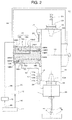
FIG. 1 is a schematic diagram showing a machine tool according to a first embodiment of the present invention, -
FIG. 2 is a longitudinal sectional view showing a nozzle according to the first embodiment of the present invention, and -
FIG. 3 is a longitudinal sectional view showing a nozzle according to a second embodiment of the present invention. - A
machine tool 10 of this embodiment will be described with reference toFIG. 1. FIG. 1 is a schematic diagram partially showing themachine tool 10 with a section taken along the vertical plane passing through arotational axis 13 of aturret 14. Themachine tool 10 is a turret-type machine tool. A machining center, a turret-type composite processing machine to which a rotary tool can be attached, etc. can be used as themachine tool 10. Theturret 14 is laid across a moving device (not shown) disposed on a bed (not shown), so as to be rotatable about therotational axis 13. A plurality ofmain spindles 15 are arranged on theturret 14. Themain spindles 15 are each provided with amain spindle hole 15A. Arotary cutting tool 24 attached to atool holder 23, and anozzle body 30, to be described later, are attached to themain spindle holes 15A. - The
machine tool 10 rotates theturret 14 and indexes therotary cutting tool 24. Themachine tool 10 cuts a workpiece W using therotary cutting tool 24. After the end of the cutting work, theturret 14 is rotated to index thenozzle body 30. Then coolant supplied from acoolant source 11 is blown from thenozzle body 30 against the workpiece W, thereby cleaning the workpiece W. At this time, themachine tool 10 inserts thenozzle body 30 into, for example, a hole H made in the workpiece W while rotating thenozzle body 30, and removes chips or the like collecting on the inner surface of the hole H. - A rotary joint 18 is provided on the leading-end side (left side in
FIG. 1 ) of theturret 14. The rotary joint 18 includes: a hollowcylindrical housing 18A that serves as a rotor; and ashaft body 18B that serves as a stator journaled in thehousing 18A. - The
shaft body 18B is formed in a generally cylindrical shape, and has a large-diameter flange 18B3 provided at the leading end thereof and a body portion 18B4. Theshaft body 18B is supported by thehousing 18A that can be rotated about therotational axis 13 bybearings 18E. The flange 18B3 is the base end of theturret 14, and is held against rotation by abracket 44 mounted to a nonrotational portion. The outer cylindrical surface of the body portion 18B4 is smoothly finished, and configured so as to make rotational contact with an inner cylindrical surface 18A3 of thehousing 18A. A plurality of flow path grooves 18B5 constituting the wall surface ofannular paths 18C are provided on the outer circumference of the body portion 18B4. The annular spaces formed by the flow path grooves 18B5 and the inner cylindrical surface 18A3 of thehousing 18A form theannular paths 18C. Packing grooves 18B6 are also circumferentially provided between the flow path grooves 18B5 and outward of the outermost flow path groove 18B5 so as to be separated from the flow path grooves 18B5. The packing grooves 18B6 are each provided with ring packing 18D. The flange 18B3 is provided with the same number of fluid inlets 18B1 as thepaths 18C. Theshaft body 18B is provided with the same number of U-shaped paths 18B2 as the fluid inlets 18B1, each of the paths 18B2 providing communication between one of the fluid inlets 18B1 and one of thepaths 18C. - The
housing 18A is fixed to theturret 14 so as to rotate about therotational axis 13. Thehousing 18A is equipped with the smoothly-finished inner cylindrical surface 18A3. Thebearings 18E are provided at either end of the inner cylindrical surface 18A3. Thebearings 18E support the flange 18B3 of theshaft body 18B and a leading-end portion of the body portion 18B4. Paths 18A2 are each provided in a manner penetrating thehousing 18A from the outer peripheral surface of thehousing 18A to the inner cylindrical surface 18A3 so as to face the paths 18B2 of theshaft body 18B when the rotary joint 18 is assembled. The outer opening of the path 18A2 serves as a fluid outlet 18A1 (second fluid outlet). That is, the path 18A2 provides communication between one of thepaths 18C and one of the fluid outlets 18A1. - Each of the fluid inlets 18B1 (second fluid inlets) communicates with one of the fluid outlets 18A1 through the
corresponding path 18C. Fluid, serving as coolant, flows into the fluid inlet 18B1 provided in theshaft body 18B. The fluid flowing into the fluid inlet 18B1 passes through the path 18B2, thepath 18C, and the path 18A2 and flows out from the fluid outlet 18A1 provided in the outer peripheral surface of thehousing 18A. Since theshaft body 18B is fixed by thebracket 44, the fluid inlet 18B1 does not rotate. Therefore, the fluid inlet 18B1 can be easily fixed to thecoolant source 11 and a pipe (first pipe) 26, including a rubber hose, metal pipe and others. Furthermore, the fluid outlet 18A1 is fixed to theturret 14. Therefore, a fixed pipe can be used as apipe 20. - It should be noted that the flow path grooves 18B5 forming the
paths 18C, the packing grooves 18B6, and the packing 18D are provided to theshaft body 18B or alternatively, may be provided to thehousing 18A. - A
positioning block 17 is provided to theturret 14 so as to be adjacent to themain spindle hole 15A. Thepositioning block 17 is provided with an insertion hole 17C into which a detent 34 (seeFIG. 2 ) of thenozzle body 30 is inserted. The insertion hole 17C is provided parallel to themain spindle hole 15A. Apath 17D is provided for communication between afluid outlet 17B (first fluid outlet) provided in the bottom face of the insertion hole 17C and afluid inlet 17A (first fluid inlet) provided in the outer surface of thepositioning block 17. The insertion hole 17C is provided with a seal 17E (seeFIG. 2 ) that seals the clearance between the insertion hole 17C and the inserteddetent 34. - The pipe (second pipe) 20 connects the fluid outlet 18A1 of the rotary joint 18 and the
fluid inlet 17A of thepositioning block 17. Thepipe 20 has both ends fixed byadapters 19. Since thepipe 20 rotates integrally with theturret 14, a strong fixed pipe, such as a metal pipe, can be used as thepipe 20. - It should be noted that, although the
pipe 20 is provided, a path passing through the interior of the rotary joint 18 and theturret 14 may be provided in place of thepipe 20. - The
machine tool 10 is also equipped with: thecoolant source 11; andvalves 12, including solenoid valves, flow-path switching valves and others. Thecoolant source 11 includes a coolant tank (not shown) and a coolant pump (not shown). The coolant tank is equipped with a separation unit (not shown) that separates the chips recovered from a machining area and coolant liquid. The coolant pump supplies coolant with a pressure suitable for cleaning to the fluid inlets 18B1 of the rotary joint 18. The same number ofvalves 12 as the positioning blocks 17 to which coolant is supplied are provided. The pipes (first pipes) 26, including rubber hoses, metal pipes and others, are connected between thecoolant source 11 and respective ones of thevalves 12 and between thevalves 12 and the fluid inlets 18B1. Thevalves 12 switch between the positioning blocks 17, depending on which of the positioning blocks 17 is to be supplied with the coolant from thecoolant source 11. - It should be noted that, in place of the
same number valves 12, serving as a plurality of opening/closing valves, as the positioning blocks 17 to which coolant is supplied, one directional control valve may be provided so as to allow switching between the positioning blocks 17 to be supplied with coolant. - Referring to
FIG. 2 , thenozzle body 30 will be described. Thenozzle body 30 is configured to be attached to themachine tool 10. The coolant supplied from thecoolant source 11 is discharged from a discharge orifice 33D to clean the workpiece W (seeFIG. 1 ). Thenozzle body 30 is equipped with a rotational shaft body 33, and is capable of indexing the direction of the discharge orifice 33D and rotating. Thenozzle body 30 can be attached not only to the turret-type machine tool 10 but also to automatic-tool-changing-type machine tools. - A
shank 31 is equipped with: ataper shank 31A that can be attached to themain spindle hole 15A; and aflange portion 31B. Theflange portion 31B is provided with akey groove 31C for aligning the phase of theshank 31 with themain spindle hole 15A when attaching theshank 31 to themain spindle hole 15A. - A
body 32 is a casing surrounding the shaft body 33, and is equipped with thedetent 34 that is inserted through the insertion hole 17C of thepositioning block 17 provided to themachine tool 10. Thebody 32 is provided with a cylindrical through-hole into which the shaft body 33 is inserted. A smoothly-finished cylindrical surface 32B is provided at the center of the through-hole. The cylindrical surface 32B is provided with a flow path groove 32C.Bearings 35 are provided at either end of the cylindrical surface 32B. Thedetent 34 is formed in a hollow cylindrical shape. Thedetent 34 is configured to be inserted into the insertion hole 17C, with the outer peripheral surface thereof fitting in the insertion hole 17C, when thenozzle body 30 is attached to themain spindle hole 15A. An L-shaped path 36 (second path) is provided so as to pass through the interior of thebody 32 from the end surface of thedetent 34 and communicate with the flow path groove 32C. - The shaft body 33 is formed in a generally cylindrical shape. The shaft body 33 is protrusively provided on the
shank 31 in such a manner as to pass through thebody 32 and protrude long in the opposite direction to theshank 31. The shaft body 33 is rotatably supported by thebody 32 through thebearings 35. The shaft body 33 is split in two bodies in the vicinity of the lower end of thebody 32, the two bodies being coupled together by bolts 33C serving as fastening bodies. The body-side portion of the shaft body 33 serves as a shaft body base portion 33A. The leading-end side (lower side in the figure) of the shaft body 33 serves as a cleaning nozzle 33B equipped with the discharge orifice 33D. - The shaft body base portion 33A is formed integrally with the
shank 31. A receptive portion 33A1 is provided coaxially with therotational axis 43 in the center of the leading-end-side end surface of the shaft body base portion 33A. The receptive portion 33A1 is formed with a key groove 41. A body portion 33A2 serving as a supporting portion of the shaft body base portion 33A is smoothly formed so as to make contact with the cylindrical surface 32B. The space formed between the outer surface of the body portion 33A2 and the flow path groove 32C serves as anannular path 37. That is, theannular path 37 is provided so as to go around the circle on the outer circumference of the body portion 33A2. - As shown in
FIG. 2 , the body portion 33A2 of the shaft body base portion 33A may be provided with a circumferential groove which faces the flow path groove 32C of thebody 32. In this case, the ring-shaped space defined by two circumferential grooves of the flow path groove 32C provided in thebody 32 and the circumferential groove provided in the shaft body base portion 33A forms theannular path 37. An inverted L path 39 (first path) is provided in such a manner as to extend radially from theannular path 37 and extend in the axial direction of themain spindle 15 along therotational axis 43 to the vicinity of the leading end of the shaft body 33. The receptive portion 33A1 is provided so as to surround thepath 39. - It should be noted that the
annular path 37 need only be provided on the outer periphery of the shaft body 33, and the groove surface constituting theannular path 37 may be either on thebody 32 or on the shaft body 33. Furthermore, thepath 39 may be formed in a T shape in which the radially-extending portion of thepath 39 is provided so as to pass through the body portion 33A2 and open into theannular path 37 on both sides of the body portion 33A2. - Annular packing grooves 32A are provided on either side of the
annular path 37 of the cylindrical surface 32B so as to be separated from theannular path 37. Each of the packing grooves 32A is provided with ring packing 38. The packing 38 prevents leakage of coolant so as to prevent damage to thebearings 35 caused by the outflow of oil from thebearings 35. The structure and type of the packing 38 are selected in accordance with the temperature, pressure, and chemical properties of the coolant. - It should be noted that the packing grooves 32A may be provided on the shaft body 33 in place of the
body 32. - Preferably, a scraper 42 or packing is provided between the
body 32 and the shaft body 33 on the outer periphery of thebody 32. If both of the scraper 42 and the packing are mounted, the scraper 42 is provided on the outer side of thebody 32, and the packing is provided toward the inner side of thebody 32. - The cleaning nozzle 33B includes: a flange 33B2; and a shaft portion 33B3 provided so as to extend along the
rotational axis 43 from the flange 33B2. An insertion portion 33B1 is provided in a protruding manner on the flange 33B2. The insertion portion 33B1 is configured to fit in the receptive portion 33A1 of the shaft body base portion 33A. The insertion portion 33B1 is provided with the key groove 41. The flange 33B2 is provided with stepped holes 33B4 into which the bolts 33C are inserted. Thepath 39 is provided along the center of the cleaning nozzle 33B from the insertion portion 33B1 to the leading end of the cleaning nozzle 33B. The leading end of the cleaning nozzle 33B is provided with the discharge orifice 33D. The discharge orifice 33D communicates with thepath 39. - The cleaning nozzle 33B is positioned by inserting a key 40 into the key groove 41 and inserting the insertion portion 33B1 into the receptive portion 33A1 of the shaft body base portion 33A. Furthermore, the cleaning nozzle 33B is fixed to the shaft body base portion 33A from the flange 33B2 by the bolts 33C.
- The cleaning nozzle 33B is fixed to the shaft body base portion 33A, with the direction and mounting height thereof positioned by the key 40 and the flange 33B2, respectively. Therefore, even if the discharge orifice 33D has directivity, the cleaning nozzle 33B is precisely fixed without causing the displacement of the discharge orifice 33D due to the replacement of the cleaning nozzle 33B. Since the
flange portion 31B of theshank 31 is also equipped with thekey groove 31C, the positions of themain spindle 15 and the discharge orifice 33D are precisely indexed if the position of thenozzle body 30 is limited by thekey groove 31C when thenozzle body 30 is attached to themain spindle 15. By these actions, even if thenozzle body 30 having directivity is used, the mounting angle and position thereof are precisely maintained. - Furthermore, the inclination of the cleaning nozzle 33B is restricted by the mounting surfaces of the flange 33B2 and the shaft body base portion 33A. Further, the
shank 31 and the shaft body base portion 33A are integrally formed. Thus, thenozzle body 30 of this embodiment is greatly reduced in rotational oscillation and assembled such that the height of the discharge orifice 33D is positioned with high accuracy with respect to theshank 31. - Preferably, packing, including an O-ring and others, is provided between the cleaning nozzle 33B and the shaft body base portion 33A. Furthermore, if the cleaning nozzle 33B has no directivity or if the cleaning nozzle 33B is a so-called spray lance and rotationally inserted, it is unnecessary to provide the key groove 41 and the key 40.
- The
nozzle body 30 of this embodiment can be attached to any machine tool which is equipped with themain spindle hole 15A and thepositioning block 17. If the coolant used for machining is supplied to thepositioning block 17, thenozzle body 30 can be readily used as a machine tool equipped with a cleaning function. - The
nozzle body 30 has a high degree of accuracy of its oscillation and position because the shaft body 33 rotates integrally with theshank 31. Furthermore, since the workpiece is fixed to themachine tool 10 with high accuracy and thenozzle body 30 is directly attached to themachine tool 10, the cleaning nozzle 33B can be inserted without interference with the workpiece W even in a region where there is only very little clearance when the cleaning nozzle 33B of thenozzle body 30 is inserted into the hole H of the workpiece W. - The discharge orifice 33D provided in the cleaning nozzle 33B is worn by the fluid discharged from the discharge orifice 33D. Since the cleaning nozzle 33B is a consumable and configured removably from the non-consumable shaft body base portion, the
nozzle body 30 is easy to maintain. - The
machine tool 10 supplies coolant to thenozzle body 30 through thepositioning block 17, and thenozzle body 30 can be directly attached to themain spindle hole 15A. Therefore, the mounting position of the cleaning nozzle 33B and the mounting position of therotary cutting tool 24 can be changed simply by changing the mounting place of thenozzle body 30. - In the
machine tool 10, the coolant used for machining is used for cleaning as it is, and therefore only onecoolant source 11 for retaining and supplying the coolant is enough. Of course, one coolant tank (not shown) is also sufficient. Since a cleaning machine and a processing machine are integrated into a single machine, the nozzle body and machine tool according to this embodiment allow shortening of the process line. Since accessory equipment, such as the coolant tank, is reduced, the setting area of the process line can be reduced. - The destination of coolant is switched by the
valves 12 separated from theturret 14. Thevalves 12 are separated from theturret 14, and therefore can be provided at a position isolated from the processing region, for example, outward of a splash cover of themachine tool 10. Since thevalves 12 equipped with electrical contacts or the like are provided in isolation from the processing region, it is possible to prevent thevalves 12 from being damaged by the splattering of coolant, oil, and chips or the like contained in the coolant. Since thevalves 12 are consumables, the replacement thereof is facilitated. - The path of coolant only includes the
pipe 26, the rotary joint 18, thepipe 20, and thepositioning block 17, all of which are arranged outside theturret 14. Thus, the pressure-resistant design and effective sectional area of the path can be freely designed. Therefore, the flow rate and pressure of the coolant can be properly selected in accordance with a required cleaning capacity. - Referring to
FIG. 3 , anozzle body 50 according to the second embodiment of the present invention will be described. The same configuration as thenozzle body 30 of the above-described first embodiment is denoted by the same reference sign and will not be described here. - The
nozzle body 50 includes ashaft body 53, which includes a shaftbody base portion 53A, acleaning nozzle 53B, and a collet fastening body 53C serving as a fastening body. - The cleaning
nozzle 53B is formed in a generally pipe shape and provided with thepath 39 in the center thereof.Discharge orifices 53D communicating with thepath 39 are provided on the same level in the leading end of thecleaning nozzle 53B so as to divide the circle in two. The cleaningnozzle 53B is a so-called cleaning lance which is inserted into the hole H while rotating. The cleaningnozzle 53B has no directivity. - A receptive portion 53A1 into which the
cleaning nozzle 53B is inserted is provided at a leading end portion (lower side in the figure) of the shaftbody base portion 53A. The receptive portion 53A1 is provided so that the cleaningnozzle 53B fits therein with therotational axis 43 as the center. A taper surface 53C2 (second taper surface) is provided to the opening of the receptive portion 53A1. An externally threaded portion 53C3 is provided on the outer circumference of the leading end portion of the shaftbody base portion 53A. - A collet 53C4 is equipped with a taper surface (first taper surface) 53C5 that abuts on the taper surface 53C2. The collet 53C4 is provided with a radial groove (not shown) on the inner and outer circumference thereof. The collet 53C4 is tightened against the externally threaded portion 53C3 from the leading-end side by a nut 53C6. At this time, the taper surface 53C5 of the collet 53C4 is reduced in diameter along the taper surface 53C2 of the shaft
body base portion 53A by tightening the nut 53C6, so that the inner diameter of the collet 53C4 is reduced. The inner surface of the collet 53C4 is biased against the cleaningnozzle 53B by the tightening force of the nut 53C6, and thus thecleaning nozzle 53B is fixed to the shaftbody base portion 53A. - The height of the
discharge orifices 53D can be adjusted by measuring the height from theflange 31B, inserting thecleaning nozzle 53B, and tightening the nut 53C6. Furthermore, at this time, the directions of thedischarge orifices 53D can be also adjusted in accordance with thekey groove 31C, and fixed by tightening the nut 53C6. As shown inFIG. 3 , the cleaningnozzle 53B may of course be fixed in abutting relation to the end surface of the receptive portion 53A1 so that the height of thedischarge orifices 53D is held constant. - It should be noted that, also in this embodiment, a key may be provided between the shaft
body base portion 53A and thecleaning nozzle 53B. In this case, the rotational direction of thecleaning nozzle 53B is positioned with respect to the shaftbody base portion 53A by the key.
Claims (5)
- A nozzle body comprising:a body;a shank that is attached to a main spindle of a machine tool:a shaft body that is provided in a protruding manner on the shank and rotatably supported by the body;an annular path that is provided on an outer circumference of the shaft body:a discharge orifice that is provided at a leading end on the opposite side of the shaft body from the shanka first path that is provided inside the shaft body, the first path providing communication between the discharge orifice and the annular path;a detent that is provided to the body; anda second path that is provided to the body and opens into the detent, the second path providing communication between the opening and the annular path.
- The nozzle body according to Claim 1, wherein the shaft body includes:a shaft body base portion that is provided inside the body;a cleaning nozzle that has the discharge orifice; anda fastening body that fastens the shaft body base portion and the cleaning nozzle.
- The nozzle body according to Claim 2, wherein the fastening body includes:a collet that has a first taper surface on an outer surface thereof;a receptive portion into which the cleaning nozzle is inserted, the receptive portion being provided to the shaft body base portion so as to surround the first path, the receptive portion having an opening, the opening having a second taper surface that abuts on the first taper surface;an externally threaded portion that is provided to the shaft body base portion; anda nut that is screw-threaded on the externally threaded portion and fastens the collet.
- The nozzle body according to Claim 2 or 3, wherein the shank has a taper shank that fits in a main spindle hole of the main spindle and a flange portion that has a key groove, and
the shaft body has a key that causes the cleaning nozzle and the shaft body base portion to match in phase in a rotational direction. - A machine tool to which the nozzle body can be attached according to any one of Claims 1 to 4, comprising:a coolant source;a turret that is supported rotatably about a rotational axis;a main spindle that is provided to the turret and has a main spindle hole to which the shank is attached;a positioning block that has: an insertion hole into which the detent is inserted; a first fluid outlet provided to the insertion hole; and a first fluid inlet communicating with the first fluid outlet, the positioning block being provided to the turret in such a manner that the insertion hole is adjacent to the main spindle hole;a rotary joint that has: a hollow rotor provided with a second fluid outlet and fixed to the turret; and a stator provided with a second fluid inlet and supported inside the rotor so as to be rotatable about the rotational axis;a first pipe that connects the second fluid inlet and the coolant source; anda second pipe that connects the second fluid outlet and the first fluid inlet.
Applications Claiming Priority (1)
| Application Number | Priority Date | Filing Date | Title |
|---|---|---|---|
| JP2015204464A JP6480300B2 (en) | 2015-10-16 | 2015-10-16 | Machine tools that can be fitted with nozzle bodies |
Publications (2)
| Publication Number | Publication Date |
|---|---|
| EP3156176A1 true EP3156176A1 (en) | 2017-04-19 |
| EP3156176B1 EP3156176B1 (en) | 2021-02-24 |
Family
ID=56737862
Family Applications (1)
| Application Number | Title | Priority Date | Filing Date |
|---|---|---|---|
| EP16175423.9A Not-in-force EP3156176B1 (en) | 2015-10-16 | 2016-06-21 | Nozzle body, and machine tool to which nozzle body can be attached |
Country Status (3)
| Country | Link |
|---|---|
| US (1) | US10081086B2 (en) |
| EP (1) | EP3156176B1 (en) |
| JP (1) | JP6480300B2 (en) |
Cited By (2)
| Publication number | Priority date | Publication date | Assignee | Title |
|---|---|---|---|---|
| CN107159921A (en) * | 2017-06-22 | 2017-09-15 | 上海大侨允德机械工业有限公司 | A kind of method and device for processing small size deep hole |
| EP3919192A1 (en) * | 2020-06-04 | 2021-12-08 | Sugino Machine Limited | Cleaning apparatus |
Families Citing this family (11)
| Publication number | Priority date | Publication date | Assignee | Title |
|---|---|---|---|---|
| JP6829633B2 (en) * | 2017-03-17 | 2021-02-10 | Dmg森精機株式会社 | Machine Tools |
| JP6738767B2 (en) * | 2017-04-27 | 2020-08-12 | モバック株式会社 | Spindle device |
| WO2018237386A1 (en) * | 2017-06-23 | 2018-12-27 | Research & Technology Solutions, Llc | APPARATUS AND METHOD FOR EXTENDING THE LIFETIME OF A CUTTING TOOL |
| KR102479419B1 (en) * | 2017-12-14 | 2022-12-21 | 삼성전자주식회사 | Deburring module and intergrated processing device including the same |
| CN108620695B (en) * | 2018-05-08 | 2020-07-24 | 承德苏垦银河连杆有限公司 | Cutting fluid cleaning machine for connecting rod threaded hole |
| US20210299764A1 (en) * | 2020-03-24 | 2021-09-30 | The Boeing Company | Tool bit, a tooling assembly for applying a fluid to a surface, and a method |
| JP6968354B2 (en) * | 2020-05-12 | 2021-11-17 | エヌティーツール株式会社 | Cooling medium injection device |
| JP7610814B2 (en) * | 2021-08-16 | 2025-01-09 | エヌティーツール株式会社 | Coolant Injection Device |
| JP7610815B2 (en) * | 2021-08-16 | 2025-01-09 | エヌティーツール株式会社 | Coolant Injection Device |
| JP7659776B2 (en) * | 2021-08-26 | 2025-04-10 | エヌティーツール株式会社 | Tool Holders and Turrets |
| CN119369144B (en) * | 2024-12-30 | 2025-04-04 | 温岭市欧凯机电有限公司 | Drilling clamp for air compressor cylinder body |
Citations (7)
| Publication number | Priority date | Publication date | Assignee | Title |
|---|---|---|---|---|
| US3791660A (en) * | 1973-01-09 | 1974-02-12 | Bendix Corp | Device for gripping, driving and supplying coolant to a cutting tool having coolant passages therein |
| EP0072657A1 (en) * | 1981-08-17 | 1983-02-23 | Kennametal Erickson U.K. Limited | An attachment for fitting to a drive spindle of a machine |
| GB2130931A (en) * | 1982-10-23 | 1984-06-13 | Okuma Machinery Works Ltd | A method of cleaning a machined surface and a chip removing tool for use in the method |
| JPS60125046U (en) * | 1984-01-30 | 1985-08-23 | マツダ株式会社 | Machine tool chip removal device |
| US4557643A (en) * | 1983-05-24 | 1985-12-10 | Bakuer Italiana S.P.A. | Distributor device for delivering coolant from the outside of a machine tool spindle |
| JPH0365905B2 (en) | 1984-12-29 | 1991-10-15 | ||
| EP0669187A2 (en) * | 1994-02-25 | 1995-08-30 | Sugino Corp. | Machine tool with parts deburrer/washer |
Family Cites Families (10)
| Publication number | Priority date | Publication date | Assignee | Title |
|---|---|---|---|---|
| US3726363A (en) * | 1971-06-08 | 1973-04-10 | Twining E | Coolant spider assembly |
| JPS57156146A (en) * | 1981-03-16 | 1982-09-27 | Kitamura Kikai Kk | Cooling apparatus for tool of machine tool |
| US4648759A (en) * | 1985-08-28 | 1987-03-10 | Waukesha Cutting Tools, Inc. | Automatic coolant inducer arrangement |
| JPH0512011U (en) * | 1991-03-13 | 1993-02-19 | 三菱マテリアル株式会社 | Holder for boring bar |
| US5265505A (en) * | 1992-10-29 | 1993-11-30 | Frechette Eugene L | Turret-lathe coolant system |
| JP3054116U (en) * | 1998-05-18 | 1998-11-24 | キソー株式会社 | Cleaning tools for milling machines |
| JP3521389B2 (en) * | 2001-08-10 | 2004-04-19 | ホーコス株式会社 | Multi-axis machine tool and method of optimizing lubricant mist flow rate of each spindle in multi-axis machine tool |
| JP4609893B2 (en) * | 2006-02-02 | 2011-01-12 | 大同メタル工業株式会社 | Tool holder |
| JP2009107054A (en) * | 2007-10-30 | 2009-05-21 | Pilot Corporation | Fluid supply device to turret |
| JP6147623B2 (en) * | 2013-09-17 | 2017-06-14 | 株式会社スギノマシン | Turret device |
-
2015
- 2015-10-16 JP JP2015204464A patent/JP6480300B2/en not_active Expired - Fee Related
-
2016
- 2016-06-02 US US15/171,738 patent/US10081086B2/en not_active Expired - Fee Related
- 2016-06-21 EP EP16175423.9A patent/EP3156176B1/en not_active Not-in-force
Patent Citations (7)
| Publication number | Priority date | Publication date | Assignee | Title |
|---|---|---|---|---|
| US3791660A (en) * | 1973-01-09 | 1974-02-12 | Bendix Corp | Device for gripping, driving and supplying coolant to a cutting tool having coolant passages therein |
| EP0072657A1 (en) * | 1981-08-17 | 1983-02-23 | Kennametal Erickson U.K. Limited | An attachment for fitting to a drive spindle of a machine |
| GB2130931A (en) * | 1982-10-23 | 1984-06-13 | Okuma Machinery Works Ltd | A method of cleaning a machined surface and a chip removing tool for use in the method |
| US4557643A (en) * | 1983-05-24 | 1985-12-10 | Bakuer Italiana S.P.A. | Distributor device for delivering coolant from the outside of a machine tool spindle |
| JPS60125046U (en) * | 1984-01-30 | 1985-08-23 | マツダ株式会社 | Machine tool chip removal device |
| JPH0365905B2 (en) | 1984-12-29 | 1991-10-15 | ||
| EP0669187A2 (en) * | 1994-02-25 | 1995-08-30 | Sugino Corp. | Machine tool with parts deburrer/washer |
Cited By (3)
| Publication number | Priority date | Publication date | Assignee | Title |
|---|---|---|---|---|
| CN107159921A (en) * | 2017-06-22 | 2017-09-15 | 上海大侨允德机械工业有限公司 | A kind of method and device for processing small size deep hole |
| EP3919192A1 (en) * | 2020-06-04 | 2021-12-08 | Sugino Machine Limited | Cleaning apparatus |
| US11839904B2 (en) | 2020-06-04 | 2023-12-12 | Sugino Machine Limited | Cleaning apparatus |
Also Published As
| Publication number | Publication date |
|---|---|
| US10081086B2 (en) | 2018-09-25 |
| EP3156176B1 (en) | 2021-02-24 |
| JP2017074653A (en) | 2017-04-20 |
| US20170106485A1 (en) | 2017-04-20 |
| JP6480300B2 (en) | 2019-03-06 |
Similar Documents
| Publication | Publication Date | Title |
|---|---|---|
| EP3156176B1 (en) | Nozzle body, and machine tool to which nozzle body can be attached | |
| US9700982B2 (en) | Rotary joint support structure spindle of machine tool, and electric motor | |
| US4534803A (en) | Method of cleaning machined surface and chip removing tool | |
| US4598617A (en) | Tool holder assembly having cutting fluid supply circuit | |
| KR200145569Y1 (en) | Fluid supply to the tool | |
| CN1668420B (en) | Tool rack for machine tools | |
| US20160016236A1 (en) | Cooling or lubricant supply for lathe tools | |
| US11919095B2 (en) | Lathe | |
| CN102355970A (en) | Coolant supply structure for turret tool head | |
| JP7262201B2 (en) | Coolant supply device | |
| EP3831529B1 (en) | Rotation indexing device | |
| KR100543365B1 (en) | Index table | |
| US20020119019A1 (en) | Machining method and mist supplying apparatus for use in the method | |
| JP4723895B2 (en) | Turret device | |
| JP2015033731A (en) | Tool holder | |
| EP1549451B1 (en) | Tool with selectively biased member and method for forming a non -axis symmetric feature | |
| CN110842221A (en) | Distributor and rotating device | |
| JP2014037026A (en) | Mist supply tool | |
| JP4390339B2 (en) | Coolant discharge device for machine tools | |
| JP5791189B2 (en) | Machining tools | |
| JP3252280U (en) | Tool holder with cooling effect | |
| JPWO2018163428A1 (en) | Machine tool spindle equipment | |
| KR102014489B1 (en) | Fluid supply system of head unit for machine tool | |
| US4498707A (en) | Cutting roller | |
| JP6738767B2 (en) | Spindle device |
Legal Events
| Date | Code | Title | Description |
|---|---|---|---|
| PUAI | Public reference made under article 153(3) epc to a published international application that has entered the european phase |
Free format text: ORIGINAL CODE: 0009012 |
|
| STAA | Information on the status of an ep patent application or granted ep patent |
Free format text: STATUS: THE APPLICATION HAS BEEN PUBLISHED |
|
| AK | Designated contracting states |
Kind code of ref document: A1 Designated state(s): AL AT BE BG CH CY CZ DE DK EE ES FI FR GB GR HR HU IE IS IT LI LT LU LV MC MK MT NL NO PL PT RO RS SE SI SK SM TR |
|
| AX | Request for extension of the european patent |
Extension state: BA ME |
|
| STAA | Information on the status of an ep patent application or granted ep patent |
Free format text: STATUS: REQUEST FOR EXAMINATION WAS MADE |
|
| 17P | Request for examination filed |
Effective date: 20171018 |
|
| RBV | Designated contracting states (corrected) |
Designated state(s): AL AT BE BG CH CY CZ DE DK EE ES FI FR GB GR HR HU IE IS IT LI LT LU LV MC MK MT NL NO PL PT RO RS SE SI SK SM TR |
|
| STAA | Information on the status of an ep patent application or granted ep patent |
Free format text: STATUS: EXAMINATION IS IN PROGRESS |
|
| 17Q | First examination report despatched |
Effective date: 20191001 |
|
| GRAP | Despatch of communication of intention to grant a patent |
Free format text: ORIGINAL CODE: EPIDOSNIGR1 |
|
| STAA | Information on the status of an ep patent application or granted ep patent |
Free format text: STATUS: GRANT OF PATENT IS INTENDED |
|
| INTG | Intention to grant announced |
Effective date: 20201204 |
|
| GRAS | Grant fee paid |
Free format text: ORIGINAL CODE: EPIDOSNIGR3 |
|
| GRAA | (expected) grant |
Free format text: ORIGINAL CODE: 0009210 |
|
| STAA | Information on the status of an ep patent application or granted ep patent |
Free format text: STATUS: THE PATENT HAS BEEN GRANTED |
|
| AK | Designated contracting states |
Kind code of ref document: B1 Designated state(s): AL AT BE BG CH CY CZ DE DK EE ES FI FR GB GR HR HU IE IS IT LI LT LU LV MC MK MT NL NO PL PT RO RS SE SI SK SM TR |
|
| REG | Reference to a national code |
Ref country code: CH Ref legal event code: EP |
|
| REG | Reference to a national code |
Ref country code: AT Ref legal event code: REF Ref document number: 1363842 Country of ref document: AT Kind code of ref document: T Effective date: 20210315 |
|
| REG | Reference to a national code |
Ref country code: IE Ref legal event code: FG4D |
|
| REG | Reference to a national code |
Ref country code: DE Ref legal event code: R096 Ref document number: 602016052982 Country of ref document: DE |
|
| REG | Reference to a national code |
Ref country code: LT Ref legal event code: MG9D |
|
| REG | Reference to a national code |
Ref country code: NL Ref legal event code: MP Effective date: 20210224 |
|
| PG25 | Lapsed in a contracting state [announced via postgrant information from national office to epo] |
Ref country code: PT Free format text: LAPSE BECAUSE OF FAILURE TO SUBMIT A TRANSLATION OF THE DESCRIPTION OR TO PAY THE FEE WITHIN THE PRESCRIBED TIME-LIMIT Effective date: 20210624 Ref country code: NO Free format text: LAPSE BECAUSE OF FAILURE TO SUBMIT A TRANSLATION OF THE DESCRIPTION OR TO PAY THE FEE WITHIN THE PRESCRIBED TIME-LIMIT Effective date: 20210524 Ref country code: BG Free format text: LAPSE BECAUSE OF FAILURE TO SUBMIT A TRANSLATION OF THE DESCRIPTION OR TO PAY THE FEE WITHIN THE PRESCRIBED TIME-LIMIT Effective date: 20210524 Ref country code: FI Free format text: LAPSE BECAUSE OF FAILURE TO SUBMIT A TRANSLATION OF THE DESCRIPTION OR TO PAY THE FEE WITHIN THE PRESCRIBED TIME-LIMIT Effective date: 20210224 Ref country code: GR Free format text: LAPSE BECAUSE OF FAILURE TO SUBMIT A TRANSLATION OF THE DESCRIPTION OR TO PAY THE FEE WITHIN THE PRESCRIBED TIME-LIMIT Effective date: 20210525 Ref country code: HR Free format text: LAPSE BECAUSE OF FAILURE TO SUBMIT A TRANSLATION OF THE DESCRIPTION OR TO PAY THE FEE WITHIN THE PRESCRIBED TIME-LIMIT Effective date: 20210224 Ref country code: LT Free format text: LAPSE BECAUSE OF FAILURE TO SUBMIT A TRANSLATION OF THE DESCRIPTION OR TO PAY THE FEE WITHIN THE PRESCRIBED TIME-LIMIT Effective date: 20210224 |
|
| PGFP | Annual fee paid to national office [announced via postgrant information from national office to epo] |
Ref country code: FR Payment date: 20210622 Year of fee payment: 6 Ref country code: DE Payment date: 20210618 Year of fee payment: 6 |
|
| REG | Reference to a national code |
Ref country code: AT Ref legal event code: MK05 Ref document number: 1363842 Country of ref document: AT Kind code of ref document: T Effective date: 20210224 |
|
| PG25 | Lapsed in a contracting state [announced via postgrant information from national office to epo] |
Ref country code: PL Free format text: LAPSE BECAUSE OF FAILURE TO SUBMIT A TRANSLATION OF THE DESCRIPTION OR TO PAY THE FEE WITHIN THE PRESCRIBED TIME-LIMIT Effective date: 20210224 Ref country code: NL Free format text: LAPSE BECAUSE OF FAILURE TO SUBMIT A TRANSLATION OF THE DESCRIPTION OR TO PAY THE FEE WITHIN THE PRESCRIBED TIME-LIMIT Effective date: 20210224 Ref country code: LV Free format text: LAPSE BECAUSE OF FAILURE TO SUBMIT A TRANSLATION OF THE DESCRIPTION OR TO PAY THE FEE WITHIN THE PRESCRIBED TIME-LIMIT Effective date: 20210224 Ref country code: RS Free format text: LAPSE BECAUSE OF FAILURE TO SUBMIT A TRANSLATION OF THE DESCRIPTION OR TO PAY THE FEE WITHIN THE PRESCRIBED TIME-LIMIT Effective date: 20210224 Ref country code: SE Free format text: LAPSE BECAUSE OF FAILURE TO SUBMIT A TRANSLATION OF THE DESCRIPTION OR TO PAY THE FEE WITHIN THE PRESCRIBED TIME-LIMIT Effective date: 20210224 |
|
| PG25 | Lapsed in a contracting state [announced via postgrant information from national office to epo] |
Ref country code: IS Free format text: LAPSE BECAUSE OF FAILURE TO SUBMIT A TRANSLATION OF THE DESCRIPTION OR TO PAY THE FEE WITHIN THE PRESCRIBED TIME-LIMIT Effective date: 20210624 |
|
| PG25 | Lapsed in a contracting state [announced via postgrant information from national office to epo] |
Ref country code: EE Free format text: LAPSE BECAUSE OF FAILURE TO SUBMIT A TRANSLATION OF THE DESCRIPTION OR TO PAY THE FEE WITHIN THE PRESCRIBED TIME-LIMIT Effective date: 20210224 Ref country code: CZ Free format text: LAPSE BECAUSE OF FAILURE TO SUBMIT A TRANSLATION OF THE DESCRIPTION OR TO PAY THE FEE WITHIN THE PRESCRIBED TIME-LIMIT Effective date: 20210224 Ref country code: SM Free format text: LAPSE BECAUSE OF FAILURE TO SUBMIT A TRANSLATION OF THE DESCRIPTION OR TO PAY THE FEE WITHIN THE PRESCRIBED TIME-LIMIT Effective date: 20210224 Ref country code: AT Free format text: LAPSE BECAUSE OF FAILURE TO SUBMIT A TRANSLATION OF THE DESCRIPTION OR TO PAY THE FEE WITHIN THE PRESCRIBED TIME-LIMIT Effective date: 20210224 |
|
| REG | Reference to a national code |
Ref country code: DE Ref legal event code: R097 Ref document number: 602016052982 Country of ref document: DE |
|
| PG25 | Lapsed in a contracting state [announced via postgrant information from national office to epo] |
Ref country code: ES Free format text: LAPSE BECAUSE OF FAILURE TO SUBMIT A TRANSLATION OF THE DESCRIPTION OR TO PAY THE FEE WITHIN THE PRESCRIBED TIME-LIMIT Effective date: 20210224 Ref country code: DK Free format text: LAPSE BECAUSE OF FAILURE TO SUBMIT A TRANSLATION OF THE DESCRIPTION OR TO PAY THE FEE WITHIN THE PRESCRIBED TIME-LIMIT Effective date: 20210224 Ref country code: RO Free format text: LAPSE BECAUSE OF FAILURE TO SUBMIT A TRANSLATION OF THE DESCRIPTION OR TO PAY THE FEE WITHIN THE PRESCRIBED TIME-LIMIT Effective date: 20210224 Ref country code: SK Free format text: LAPSE BECAUSE OF FAILURE TO SUBMIT A TRANSLATION OF THE DESCRIPTION OR TO PAY THE FEE WITHIN THE PRESCRIBED TIME-LIMIT Effective date: 20210224 |
|
| PLBE | No opposition filed within time limit |
Free format text: ORIGINAL CODE: 0009261 |
|
| STAA | Information on the status of an ep patent application or granted ep patent |
Free format text: STATUS: NO OPPOSITION FILED WITHIN TIME LIMIT |
|
| PG25 | Lapsed in a contracting state [announced via postgrant information from national office to epo] |
Ref country code: MC Free format text: LAPSE BECAUSE OF FAILURE TO SUBMIT A TRANSLATION OF THE DESCRIPTION OR TO PAY THE FEE WITHIN THE PRESCRIBED TIME-LIMIT Effective date: 20210224 Ref country code: AL Free format text: LAPSE BECAUSE OF FAILURE TO SUBMIT A TRANSLATION OF THE DESCRIPTION OR TO PAY THE FEE WITHIN THE PRESCRIBED TIME-LIMIT Effective date: 20210224 |
|
| REG | Reference to a national code |
Ref country code: CH Ref legal event code: PL |
|
| 26N | No opposition filed |
Effective date: 20211125 |
|
| GBPC | Gb: european patent ceased through non-payment of renewal fee |
Effective date: 20210621 |
|
| PG25 | Lapsed in a contracting state [announced via postgrant information from national office to epo] |
Ref country code: SI Free format text: LAPSE BECAUSE OF FAILURE TO SUBMIT A TRANSLATION OF THE DESCRIPTION OR TO PAY THE FEE WITHIN THE PRESCRIBED TIME-LIMIT Effective date: 20210224 |
|
| REG | Reference to a national code |
Ref country code: BE Ref legal event code: MM Effective date: 20210630 |
|
| PG25 | Lapsed in a contracting state [announced via postgrant information from national office to epo] |
Ref country code: LU Free format text: LAPSE BECAUSE OF NON-PAYMENT OF DUE FEES Effective date: 20210621 |
|
| PG25 | Lapsed in a contracting state [announced via postgrant information from national office to epo] |
Ref country code: LI Free format text: LAPSE BECAUSE OF NON-PAYMENT OF DUE FEES Effective date: 20210630 Ref country code: IT Free format text: LAPSE BECAUSE OF FAILURE TO SUBMIT A TRANSLATION OF THE DESCRIPTION OR TO PAY THE FEE WITHIN THE PRESCRIBED TIME-LIMIT Effective date: 20210224 Ref country code: IE Free format text: LAPSE BECAUSE OF NON-PAYMENT OF DUE FEES Effective date: 20210621 Ref country code: GB Free format text: LAPSE BECAUSE OF NON-PAYMENT OF DUE FEES Effective date: 20210621 Ref country code: CH Free format text: LAPSE BECAUSE OF NON-PAYMENT OF DUE FEES Effective date: 20210630 |
|
| PG25 | Lapsed in a contracting state [announced via postgrant information from national office to epo] |
Ref country code: IS Free format text: LAPSE BECAUSE OF FAILURE TO SUBMIT A TRANSLATION OF THE DESCRIPTION OR TO PAY THE FEE WITHIN THE PRESCRIBED TIME-LIMIT Effective date: 20210624 |
|
| PG25 | Lapsed in a contracting state [announced via postgrant information from national office to epo] |
Ref country code: BE Free format text: LAPSE BECAUSE OF NON-PAYMENT OF DUE FEES Effective date: 20210630 |
|
| REG | Reference to a national code |
Ref country code: DE Ref legal event code: R119 Ref document number: 602016052982 Country of ref document: DE |
|
| PG25 | Lapsed in a contracting state [announced via postgrant information from national office to epo] |
Ref country code: FR Free format text: LAPSE BECAUSE OF NON-PAYMENT OF DUE FEES Effective date: 20220630 |
|
| PG25 | Lapsed in a contracting state [announced via postgrant information from national office to epo] |
Ref country code: HU Free format text: LAPSE BECAUSE OF FAILURE TO SUBMIT A TRANSLATION OF THE DESCRIPTION OR TO PAY THE FEE WITHIN THE PRESCRIBED TIME-LIMIT; INVALID AB INITIO Effective date: 20160621 Ref country code: DE Free format text: LAPSE BECAUSE OF NON-PAYMENT OF DUE FEES Effective date: 20230103 |
|
| PG25 | Lapsed in a contracting state [announced via postgrant information from national office to epo] |
Ref country code: CY Free format text: LAPSE BECAUSE OF FAILURE TO SUBMIT A TRANSLATION OF THE DESCRIPTION OR TO PAY THE FEE WITHIN THE PRESCRIBED TIME-LIMIT Effective date: 20210224 |
|
| PG25 | Lapsed in a contracting state [announced via postgrant information from national office to epo] |
Ref country code: MK Free format text: LAPSE BECAUSE OF FAILURE TO SUBMIT A TRANSLATION OF THE DESCRIPTION OR TO PAY THE FEE WITHIN THE PRESCRIBED TIME-LIMIT Effective date: 20210224 |
|
| PG25 | Lapsed in a contracting state [announced via postgrant information from national office to epo] |
Ref country code: TR Free format text: LAPSE BECAUSE OF FAILURE TO SUBMIT A TRANSLATION OF THE DESCRIPTION OR TO PAY THE FEE WITHIN THE PRESCRIBED TIME-LIMIT Effective date: 20210224 |
|
| PG25 | Lapsed in a contracting state [announced via postgrant information from national office to epo] |
Ref country code: MT Free format text: LAPSE BECAUSE OF FAILURE TO SUBMIT A TRANSLATION OF THE DESCRIPTION OR TO PAY THE FEE WITHIN THE PRESCRIBED TIME-LIMIT Effective date: 20210224 |