EP3156158A1 - Hollow rotating shaft-finishing method and hollow rotating shaft - Google Patents
Hollow rotating shaft-finishing method and hollow rotating shaft Download PDFInfo
- Publication number
- EP3156158A1 EP3156158A1 EP15839664.8A EP15839664A EP3156158A1 EP 3156158 A1 EP3156158 A1 EP 3156158A1 EP 15839664 A EP15839664 A EP 15839664A EP 3156158 A1 EP3156158 A1 EP 3156158A1
- Authority
- EP
- European Patent Office
- Prior art keywords
- rotating shaft
- hollow rotating
- center
- shaft
- axial direction
- Prior art date
- Legal status (The legal status is an assumption and is not a legal conclusion. Google has not performed a legal analysis and makes no representation as to the accuracy of the status listed.)
- Withdrawn
Links
Images




Classifications
-
- B—PERFORMING OPERATIONS; TRANSPORTING
- B23—MACHINE TOOLS; METAL-WORKING NOT OTHERWISE PROVIDED FOR
- B23B—TURNING; BORING
- B23B5/00—Turning-machines or devices specially adapted for particular work; Accessories specially adapted therefor
- B23B5/08—Turning-machines or devices specially adapted for particular work; Accessories specially adapted therefor for turning axles, bars, rods, tubes, rolls, i.e. shaft-turning lathes, roll lathes; Centreless turning
-
- B—PERFORMING OPERATIONS; TRANSPORTING
- B23—MACHINE TOOLS; METAL-WORKING NOT OTHERWISE PROVIDED FOR
- B23Q—DETAILS, COMPONENTS, OR ACCESSORIES FOR MACHINE TOOLS, e.g. ARRANGEMENTS FOR COPYING OR CONTROLLING; MACHINE TOOLS IN GENERAL CHARACTERISED BY THE CONSTRUCTION OF PARTICULAR DETAILS OR COMPONENTS; COMBINATIONS OR ASSOCIATIONS OF METAL-WORKING MACHINES, NOT DIRECTED TO A PARTICULAR RESULT
- B23Q15/00—Automatic control or regulation of feed movement, cutting velocity or position of tool or work
- B23Q15/007—Automatic control or regulation of feed movement, cutting velocity or position of tool or work while the tool acts upon the workpiece
- B23Q15/013—Control or regulation of feed movement
- B23Q15/02—Control or regulation of feed movement according to the instantaneous size and the required size of the workpiece acted upon
-
- B—PERFORMING OPERATIONS; TRANSPORTING
- B23—MACHINE TOOLS; METAL-WORKING NOT OTHERWISE PROVIDED FOR
- B23B—TURNING; BORING
- B23B1/00—Methods for turning or working essentially requiring the use of turning-machines; Use of auxiliary equipment in connection with such methods
-
- B—PERFORMING OPERATIONS; TRANSPORTING
- B23—MACHINE TOOLS; METAL-WORKING NOT OTHERWISE PROVIDED FOR
- B23Q—DETAILS, COMPONENTS, OR ACCESSORIES FOR MACHINE TOOLS, e.g. ARRANGEMENTS FOR COPYING OR CONTROLLING; MACHINE TOOLS IN GENERAL CHARACTERISED BY THE CONSTRUCTION OF PARTICULAR DETAILS OR COMPONENTS; COMBINATIONS OR ASSOCIATIONS OF METAL-WORKING MACHINES, NOT DIRECTED TO A PARTICULAR RESULT
- B23Q15/00—Automatic control or regulation of feed movement, cutting velocity or position of tool or work
- B23Q15/007—Automatic control or regulation of feed movement, cutting velocity or position of tool or work while the tool acts upon the workpiece
- B23Q15/013—Control or regulation of feed movement
- B23Q15/04—Control or regulation of feed movement according to the final size of the previously-machined workpiece
-
- B—PERFORMING OPERATIONS; TRANSPORTING
- B23—MACHINE TOOLS; METAL-WORKING NOT OTHERWISE PROVIDED FOR
- B23Q—DETAILS, COMPONENTS, OR ACCESSORIES FOR MACHINE TOOLS, e.g. ARRANGEMENTS FOR COPYING OR CONTROLLING; MACHINE TOOLS IN GENERAL CHARACTERISED BY THE CONSTRUCTION OF PARTICULAR DETAILS OR COMPONENTS; COMBINATIONS OR ASSOCIATIONS OF METAL-WORKING MACHINES, NOT DIRECTED TO A PARTICULAR RESULT
- B23Q17/00—Arrangements for observing, indicating or measuring on machine tools
- B23Q17/20—Arrangements for observing, indicating or measuring on machine tools for indicating or measuring workpiece characteristics, e.g. contour, dimension, hardness
Definitions
- the present disclosure relates to a hollow rotating shaft finishing method to finish the outer circumference of a hollow rotating shaft having a predetermined inner diameter to a predetermined outer diameter in the axial direction (in the axial direction of the hollow rotating shaft) or the like.
- a hollow rotating shaft such as a turbine shaft used in a gas turbine
- the following process is generally performed.
- a virtual reference shaft center is set to process the outer circumference of the hollow rotating shaft.
- a cutting tool is used to cut the outer circumference of the hollow rotating shaft in the axial direction by giving a cut to the cutting tool and moving the cutting tool in the axial direction relatively to the hollow rotating shaft while rotating the hollow rotating shaft about the virtual reference shaft center.
- the amount of unbalance is measured at each end of the hollow rotating shaft in the axial direction with a dynamic balancing machine at a rotation speed smaller than the actual rotation speed. Based on the result of measurement, balance lands at both ends of the hollow rotating shaft in the axial direction are cut for balancing of the hollow rotating shaft.
- Patent Documents 1 to 3 The conventional arts relating to the present disclosure include techniques illustrated in Patent Documents 1 to 3.
- the hollow rotating shaft is balanced by cutting the balance land at each end of the hollow rotating shaft in the axial direction. Accordingly, the middle part of hollow rotating shaft in the axial direction tends to remain unbalanced.
- the hollow rotating shaft is used in the rotary machine, such as a gas turbine, an increase in rotation speed of the hollow rotating shaft could increase runout of the middle part of the hollow rotating shaft in the axial direction. It is therefore desired to further improve the reliability of the hollow rotating shaft at high rotation speed.
- An object of the present disclosure is to provide a hollow rotating shaft finishing method of a new configuration and the like which are capable of solving the aforementioned problem.
- a first aspect of the present disclosure is a hollow rotating shaft finishing method (a method of finishing a hollow rotating shaft) to finish the outer circumference (outer circumferential surface) of a hollow rotating shaft having a predetermined inner diameter to a predetermined outer diameter in the axial direction of the hollow rotating shaft, the method including: a setting step of setting a virtual reference shaft center for processing the outer circumference of the hollow rotating shaft; a measurement step of measuring a deviation vector (the direction and magnitude of the deviation vector) of the center position of the inner circumference (inner circumferential surface) of the hollow rotating shaft with respect to the virtual reference shaft center in the axial direction after the setting step; and a cutting step of using a cutting tool to cut the outer circumference of the hollow rotating shaft in the axial direction after the measurement step by giving a cut to the cutting tool while rotating the hollow rotating shaft about the virtual reference shaft center and moving the cutting tool relatively to the hollow rotating shaft in the axial direction while adjusting the position of the cutting tool in the direction orthogonal to the virtual reference shaft center so that the center position (
- the amount corresponding to the magnitude of the deviation vector of the inner circumference is equal to any one of (the magnitude of the deviation vector of the center position of the inner circumference) multiplied by (a predetermined inner diameter) 2 /(a predetermined outer diameter) 2 ) and the magnitude of the deviation vector of the inner circumference.
- the axial direction refers to the axial direction of the hollow rotating shaft.
- the "predetermined inner diameter” refers to an inner diameter previously configured, and the value (the predetermined value of the inner diameter) thereof does not need to be constant in the axial direction.
- the "predetermined outer diameter” refers to an outer diameter previously configured, and the value (the predetermined value of the outer diameter) thereof does not need to be constant in the axial direction.
- “To measure” refers to direct measurement and calculation based on the results of measurement”.
- the cutting tool includes a turning tool, a cutting wheel (a grinding wheel), and the like.
- the position of the cutting tool is adjusted in the direction orthogonal to the virtual reference shaft center so that the center position of the outer circumference of the hollow rotating shaft is deviated from the virtual reference shaft center in the same direction as the deviation vector by an amount corresponding to the magnitude of the deviation vector.
- This can reduce unbalance of the hollow rotating shaft to zero or close to zero in the axial direction. In other words, it is possible to reduce unbalance to zero or close to zero in the middle of the hollow rotating shaft in the axial direction as well as at both ends of the hollow rotating shaft in the axial direction.
- the present disclosure it is possible to reduce unbalance to zero or close to zero at both ends and in the middle of the hollow rotating shaft in the axial direction.
- a hollow rotating shaft finishing method (a method of finishing a hollow rotating shaft) according to the embodiment of the present disclosure is a method to finish an outer circumference (outer circumferential surface) 10o of the hollow rotating shaft 10, which has a predetermined inner diameter Ri, to a predetermined outer diameter Ro in the axial direction (the axial direction of the hollow rotating shaft 10).
- the hollow rotating shaft finishing method according to the embodiment of the present disclosure includes (i) a setting step, (ii) an intermediate cutting step, (iii) a measurement step, and (iv) a cutting step.
- the follow rotating shaft 10 as a target to be finished by the hollow rotating shaft finishing method according to the embodiment of the present disclosure is a low-pressure turbine shaft used in an aircraft gas turbine as illustrated in Japanese Unexamined Patent Application Publication No. 2000-320615 (Patent Literature 2 described above), for example.
- the concrete contents of each step of the hollow rotating shaft finishing method are as follows.
- the hollow rotating shaft 10 is set horizontally on a pair of shaft supporting mechanisms 12 and 14 of an inner diameter runout-measuring device (partially illustrated).
- a runout gauge 16 such as an indicator, is used to measure runout of the inner circumference (inner circumferential surface) 10i of the hollow rotating shaft 10 with respect to the reference position (indicated by dashed and dotted lines) at both ends and in the middle of the hollow rotating shaft 10 in the axial direction while rotating the hollow rotating shaft 10 about the shaft center 10c (the shaft center of the hollow rotating shaft 10).
- a virtual reference shaft center VS see FIG.
- an end of the outer circumference 10o of the hollow rotating shaft 10 in the axial direction is gripped with a chuck 20 of a main shaft 18 of a machining center or lathe (partially illustrated).
- the shaft center of the main shaft 18 is coincident with the virtual reference shaft center VS of the hollow rotating shaft 10.
- the other end of the outer circumference 10o of the hollow rotating shaft 10 is rotatably supported with a steady rest 22 of the machining center or lathe.
- the hollow rotating shaft 10 is thus set at a predetermined position of the machining center or lathe.
- a turning tool 24 is used to perform cutting at both ends of the outer circumference 10o of the hollow rotating shaft 10 in the axial direction by giving a cut to the turning tool 24 while rotating the hollow rotating shaft 10 integrally with the main shaft 18 about the virtual reference shaft center VS.
- Reference faces 10af and 10bf to specify the virtual reference shaft center VS are thus formed at both ends of the outer circumference 10o of the hollow rotating shaft 10 in the axial direction, thus finally setting the virtual reference shaft center VS.
- the position of the steady rest 22 in the axial direction (in the direction of the virtual reference shaft center VS) is adjusted so that the steady rest 22 rotatably supports the reference face 10bf of the hollow rotating shaft 10.
- the turning tool 24 is given a cut and is moved in the axial direction for intermediate cutting of a part of the outer circumference 10o of the hollow rotating shaft 10 with a finishing allowance for cutting left excepting the end thereof.
- a cutting tool (not illustrated) for inner diameter processing is used to perform inner diameter finishing for the other end of the inner circumference 10i of the hollow rotating shaft 10 in the axial direction, thus forming an inner diameter end 10bs.
- the grip of the chuck 20 of the main shaft 18 and the support of the steady rest 22 are released, and an end of the outer circumference 10o of the hollow rotating shaft 10 is gripped with the chuck 20 of the main shaft 18 as illustrated in FIG. 4 .
- the other end of the hollow rotating shaft 10 is rotatably supported with the steady rest 22. While the hollow rotating shaft 10 is rotated integrally with the main shaft 18 about the virtual reference shaft center VS, the turning tool 24 is given a cut and is moved in the axial direction for cutting of the end of the outer circumference 10o of the hollow rotating shaft 10.
- a cutting tool for inner diameter processing is used to perform inner diameter finishing for the end of the inner circumference 10i of the hollow rotating shaft 10 in the axial direction, thus forming an inner diameter end 10as.
- the grip of the chuck 20 of the main shaft 18 and the support of the steady rest 22 are released, and the hollow rotating shaft 10 is detached from the machining center or lathe.
- the end of the outer circumference 10o of the hollow rotating shaft 10 is gripped with a chuck 28 of a main shaft 26 of a machining center or lathe (partially illustrated) for balancing so that the shaft center of the main shaft 26 is coincident with the virtual reference shaft center VS of the hollow rotating shaft 10.
- the other end of the outer circumference 10o of the hollow rotating shaft 10 is rotatably supported by a steady rest 30 of the machining center or lathe for balancing.
- the hollow rotating shaft 10 is thereby set at the predetermined position of the machining center or lathe for balancing.
- an ultrasonic contact 32 which is movable in the direction orthogonal to the virtual reference shaft center VS, is used to measure variations in thickness of the hollow rotating shaft 10 in the circumferential direction (in the circumferential direction of the hollow rotating shaft 10) by bringing the ultrasonic contact 32 into contact with the outer circumference 10o of the hollow rotating shaft 10 through an ultrasonic contact medium, such as water, for example while rotating the hollow rotating shaft 10 integrally with the main shaft 26 about the virtual reference shaft center VS.
- an ultrasonic contact medium such as water
- a position measuring device 34 such as a laser displacement meter, for example, which is provided for the ultrasonic contact 32, is used to measure circumferential variations in position of the ultrasonic contact 32 in the direction orthogonal to the virtual reference shaft center VS.
- the measurements by the ultrasonic contact 32 and position measuring device 34 are continuously or intermittently performed in the axial direction.
- a deviation vector ⁇ Di (the direction and magnitude of the deviation vector ⁇ Di) of a center position CPi of the inner circumference 10i of the hollow rotating shaft 10 with respect to the virtual reference shaft center VS is calculated in the axial direction by a controller (not illustrated) of the machining center or lathe for balancing.
- the deviation vector ⁇ Di of the center position CPi of the inner circumference 10i of the hollow rotating shaft 10 with respect to the virtual reference shaft center VS is calculated in the axial direction using the ultrasonic contact 32 and position measuring device 34 (see FIGS. 6(a) and 6(b)).
- FIG. 6(a) illustrates a virtual circle VC about the virtual reference shaft center VS.
- the deviation vector ⁇ Di of the center position of the inner circumference 10i of the hollow rotating shaft 10 with respect to the virtual reference shaft center VS may be calculated in the axial direction by using the runout gauge 16 such as an indicator instead of the ultrasonic contact 32 and position measuring device 34.
- a finishing turning tool 36 which is movable in the direction orthogonal to the virtual reference shaft center VS through drive of a servomotor (not illustrated), is used to cut the outer circumference 10o of the hollow rotating shaft 10 in the axial direction by giving a cut to the finishing turning tool 36 and moving the finishing turning tool 36 in the axial direction while rotating the hollow rotating shaft 10 integrally with the main shaft 26 about the virtual reference shaft center VS.
- the position of the finishing turning tool 36 is adjusted in the direction orthogonal to the virtual reference shaft center VS through drive of the servomotor so that a center position (the real processing center) CPo of the outer circumference 10o of the hollow rotating shaft 10 is deviated from the virtual reference shaft center VS in the same direction as the direction (the direction of deviation) of the deviation vector ⁇ Di by an amount corresponding to the magnitude (an amount of deviation)
- of the deviation vector ⁇ Di in other words, the magnitude
- the position of the finishing turning tool 36 is adjusted in the direction orthogonal to the virtual reference shaft center VS so that the center position CPo of the outer circumference 10o of the hollow rotating shaft 10 is deviated from the virtual reference shaft center VS in the same direction as the deviation vector ⁇ Di by an amount corresponding to the magnitude
- the direction of an unbalance Ai of the inner part per unit length from the virtual circle VC to the inner circumference 10i in the hollow rotating shaft 10 is opposite to the direction of the deviation vector ⁇ Di, and the magnitude of the unbalance Ai is
- the direction of an unbalance Ao of the outer part per unit length from the virtual circle VC to the outer circumference 10o in the hollow rotating shaft 10 is the same as the direction of the deviation vector ⁇ Do, and the magnitude of the unbalance Ao is equal to
- the unbalance of the hollow rotating shaft 10 can be equal to or close to zero at both ends and in the middle of the hollow rotating shaft 10 in the axial direction.
- runout of the hollow rotating shaft 10 is sufficiently reduced even if the rotation speed of the hollow rotating shaft 10 increases. It is therefore possible to further improve the reliability of the hollow rotating shaft 10 at high rotation speed.
- the present disclosure is not limited to the description of the aforementioned embodiment and can be implemented in various modes.
- the scope of right in the present disclosure includes the hollow rotating shaft 10 finished by the hollow rotating shaft finishing method.
- ⁇ Di deviation vector of the center position of the inner circumference of the hollow rotating shaft
- ⁇ Do deviation vector of the center position of the outer circumference of the hollow rotating shaft
- Ai unbalance per unit length of inner part of the hollow rotating shaft
- Ao unbalance per unit length of outer part of the hollow rotating shaft
- CPi center position of the inner circumference of the hollow rotating shaft
- CPo center position of the outer circumference of the hollow rotating shaft
- VC virtual circle
- VS virtual reference shaft center
- 10i inner circumference
- 10o outer circumference
Landscapes
- Engineering & Computer Science (AREA)
- Mechanical Engineering (AREA)
- Testing Of Balance (AREA)
- Turning (AREA)
- Automatic Control Of Machine Tools (AREA)
Abstract
Description
- The present disclosure relates to a hollow rotating shaft finishing method to finish the outer circumference of a hollow rotating shaft having a predetermined inner diameter to a predetermined outer diameter in the axial direction (in the axial direction of the hollow rotating shaft) or the like.
- To finish the outer circumference of a hollow rotating shaft, such as a turbine shaft used in a gas turbine, to a predetermined outer diameter in the axial direction, the following process is generally performed.
- First, a virtual reference shaft center is set to process the outer circumference of the hollow rotating shaft. Next, a cutting tool is used to cut the outer circumference of the hollow rotating shaft in the axial direction by giving a cut to the cutting tool and moving the cutting tool in the axial direction relatively to the hollow rotating shaft while rotating the hollow rotating shaft about the virtual reference shaft center. Subsequently, the amount of unbalance is measured at each end of the hollow rotating shaft in the axial direction with a dynamic balancing machine at a rotation speed smaller than the actual rotation speed. Based on the result of measurement, balance lands at both ends of the hollow rotating shaft in the axial direction are cut for balancing of the hollow rotating shaft.
- The conventional arts relating to the present disclosure include techniques illustrated in Patent Documents 1 to 3.
-
- Patent Document 1:
JP 2011-73525 A - Patent Document 2:
JP 2000-320615 A - Patent Document 3:
JP H07-167731 A - As described above, the hollow rotating shaft is balanced by cutting the balance land at each end of the hollow rotating shaft in the axial direction. Accordingly, the middle part of hollow rotating shaft in the axial direction tends to remain unbalanced. When the hollow rotating shaft is used in the rotary machine, such as a gas turbine, an increase in rotation speed of the hollow rotating shaft could increase runout of the middle part of the hollow rotating shaft in the axial direction. It is therefore desired to further improve the reliability of the hollow rotating shaft at high rotation speed.
- An object of the present disclosure is to provide a hollow rotating shaft finishing method of a new configuration and the like which are capable of solving the aforementioned problem.
- A first aspect of the present disclosure is a hollow rotating shaft finishing method (a method of finishing a hollow rotating shaft) to finish the outer circumference (outer circumferential surface) of a hollow rotating shaft having a predetermined inner diameter to a predetermined outer diameter in the axial direction of the hollow rotating shaft, the method including: a setting step of setting a virtual reference shaft center for processing the outer circumference of the hollow rotating shaft; a measurement step of measuring a deviation vector (the direction and magnitude of the deviation vector) of the center position of the inner circumference (inner circumferential surface) of the hollow rotating shaft with respect to the virtual reference shaft center in the axial direction after the setting step; and a cutting step of using a cutting tool to cut the outer circumference of the hollow rotating shaft in the axial direction after the measurement step by giving a cut to the cutting tool while rotating the hollow rotating shaft about the virtual reference shaft center and moving the cutting tool relatively to the hollow rotating shaft in the axial direction while adjusting the position of the cutting tool in the direction orthogonal to the virtual reference shaft center so that the center position (actual processing center) of the outer circumference of the hollow rotating shaft is deviated from the virtual reference shaft center in the same direction as the direction (the direction of deviation) of the deviation vector of the inner circumference by an amount (the amount of deviation) corresponding to the magnitude of the deviation vector of the inner circumference.
- Herein, the amount corresponding to the magnitude of the deviation vector of the inner circumference is equal to any one of (the magnitude of the deviation vector of the center position of the inner circumference) multiplied by (a predetermined inner diameter)2/(a predetermined outer diameter)2) and the magnitude of the deviation vector of the inner circumference.
- In the specification and claims of the application, the axial direction refers to the axial direction of the hollow rotating shaft. The "predetermined inner diameter" refers to an inner diameter previously configured, and the value (the predetermined value of the inner diameter) thereof does not need to be constant in the axial direction. The "predetermined outer diameter" refers to an outer diameter previously configured, and the value (the predetermined value of the outer diameter) thereof does not need to be constant in the axial direction. "To measure" refers to direct measurement and calculation based on the results of measurement". The cutting tool includes a turning tool, a cutting wheel (a grinding wheel), and the like.
- According to the characteristics of the present disclosure, in the process of cutting the outer circumference of the hollow rotating shaft in the axial direction, the position of the cutting tool is adjusted in the direction orthogonal to the virtual reference shaft center so that the center position of the outer circumference of the hollow rotating shaft is deviated from the virtual reference shaft center in the same direction as the deviation vector by an amount corresponding to the magnitude of the deviation vector. This can reduce unbalance of the hollow rotating shaft to zero or close to zero in the axial direction. In other words, it is possible to reduce unbalance to zero or close to zero in the middle of the hollow rotating shaft in the axial direction as well as at both ends of the hollow rotating shaft in the axial direction.
- According to the present disclosure, it is possible to reduce unbalance to zero or close to zero at both ends and in the middle of the hollow rotating shaft in the axial direction. In the case of using the hollow rotating shaft in a rotary machine, it is possible to sufficiently reduce runout of the hollow rotating shaft even when the rotation speed of the hollow rotating shaft increases, thus further improving the reliability of the hollow rotating shaft at high rotation speed.
-
-
FIG. 1(a) is a schematic front view of a device of measuring run-out of the inner circumference, illustrating a setting step in a hollow rotating shaft finishing method according to an embodiment of the disclosure.FIG. 1 (b) is a view taken along a line IB-IB inFIG. 1 (a). FIG. 1 (c) is a view taken along a line IC-IC inFIG. 1 (a). FIG. 1 (d) is a view taken along a line ID-ID inFIG. 1 (a) . -
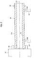
FIG. 2 is a schematic top view of a machining center or a lathe, illustrating the setting step in the hollow rotating shaft finishing method according to the embodiment of the disclosure. -
FIG. 3 is a schematic top view of the machining center or lathe, illustrating an intermediate cutting step in the hollow rotating shaft finishing method according to the embodiment of the disclosure. -
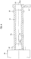
FIG. 4 is a schematic top view of the machining center or lathe, illustrating the intermediate cutting step in the hollow rotating shaft finishing method according to the embodiment of the disclosure. -
FIG. 5 is a schematic top view of a machining center or a lathe for balancing, illustrating a measurement step in the hollow rotating shaft finishing method according to the embodiment of the disclosure. -
FIG. 6(a) is a view illustrating any intermediate cross section between both ends of the hollow rotating shaft in the axial direction after the intermediate cutting step, andFIG. 6(b) is an enlarged view of a part indicated by an arrow VIB. -
FIG. 7 is a schematic top view of the machining center or lathe for balancing, illustrating a measurement step in the hollow rotating shaft finishing method according to the embodiment of the disclosure. -
FIG. 8(a) is an enlarged view illustrating a case where a deviation vector of the center position of the outer circumference of the hollow rotating shaft with respect to the virtual reference shaft center has a magnitude equal to the Ri2/Ro2 multiplied by the magnitude of the deviation vector of the center position of the inner circumference of the hollow rotating shaft. -
FIG. 8(b) is a view of any given intermediate cross-section between both ends of the hollow rotating shaft in the axial direction, the view illustrating unbalance per unit length in inner part of the hollow rotating shaft and unbalance per unit length in outer part of the hollow rotating shaft. -
FIG. 9(a) is an enlarged view illustrating a case where the deviation vector of the center position of the outer circumference of the hollow rotating shaft with respect to the virtual reference shaft center has a magnitude equal to the magnitude of the deviation vector of the center position of the inner circumference of the hollow rotating shaft. -
FIG. 9(b) is a view of any given intermediate cross-section between both ends of the hollow rotating shaft in the axial direction, the view illustrating unbalance per unit length in inner part of the hollow rotating shaft and unbalance per unit length in outer part of the hollow rotating shaft. - Hereinafter, a description is given of an embodiment of the present disclosure with reference to the drawings.
- As illustrated in
FIGS. 1 and7 and other drawings, a hollow rotating shaft finishing method (a method of finishing a hollow rotating shaft) according to the embodiment of the present disclosure is a method to finish an outer circumference (outer circumferential surface) 10o of the hollow rotatingshaft 10, which has a predetermined inner diameter Ri, to a predetermined outer diameter Ro in the axial direction (the axial direction of the hollow rotating shaft 10). The hollow rotating shaft finishing method according to the embodiment of the present disclosure includes (i) a setting step, (ii) an intermediate cutting step, (iii) a measurement step, and (iv) a cutting step. Herein, the follow rotatingshaft 10 as a target to be finished by the hollow rotating shaft finishing method according to the embodiment of the present disclosure, which is schematically illustrated, is a low-pressure turbine shaft used in an aircraft gas turbine as illustrated in Japanese Unexamined Patent Application Publication No.2000-320615 - As illustrated in
FIGS. 1 (a) to 1 (d) , the hollow rotatingshaft 10 is set horizontally on a pair ofshaft supporting mechanisms runout gauge 16, such as an indicator, is used to measure runout of the inner circumference (inner circumferential surface) 10i of the hollow rotatingshaft 10 with respect to the reference position (indicated by dashed and dotted lines) at both ends and in the middle of the hollow rotatingshaft 10 in the axial direction while rotating the hollow rotatingshaft 10 about the shaft center 10c (the shaft center of the hollow rotating shaft 10). Based on the results of measurement from therunout gauge 16, a virtual reference shaft center VS (seeFIG. 2 ) for processing of the outer circumference 10o of the hollow rotatingshaft 10 is tentatively set by placing an emphasis on the runout in the middle of theinner circumference 10i of the hollow rotatingshaft 10 in the axial direction. The hollow rotatingshaft 10 is detached from the inner diameter runout-measuring device by releasing the support of the pair ofshaft supporting mechanisms - After the hollow rotating
shaft 10 is detached from the inner diameter runout-measuring device, as illustrated inFIG. 2 , an end of the outer circumference 10o of the hollow rotatingshaft 10 in the axial direction is gripped with achuck 20 of amain shaft 18 of a machining center or lathe (partially illustrated). The shaft center of themain shaft 18 is coincident with the virtual reference shaft center VS of the hollow rotatingshaft 10. The other end of the outer circumference 10o of the hollow rotatingshaft 10 is rotatably supported with asteady rest 22 of the machining center or lathe. The hollow rotatingshaft 10 is thus set at a predetermined position of the machining center or lathe. - After the hollow rotating
shaft 10 is set in the machining center or lathe, aturning tool 24 is used to perform cutting at both ends of the outer circumference 10o of the hollow rotatingshaft 10 in the axial direction by giving a cut to theturning tool 24 while rotating the hollow rotatingshaft 10 integrally with themain shaft 18 about the virtual reference shaft center VS. Reference faces 10af and 10bf to specify the virtual reference shaft center VS are thus formed at both ends of the outer circumference 10o of the hollow rotatingshaft 10 in the axial direction, thus finally setting the virtual reference shaft center VS. - After the measurement step, as illustrated in
FIG. 3 , the position of thesteady rest 22 in the axial direction (in the direction of the virtual reference shaft center VS) is adjusted so that thesteady rest 22 rotatably supports the reference face 10bf of the hollow rotatingshaft 10. While the hollow rotatingshaft 10 is rotated integrally with themain shaft 18 about the virtual reference shaft center VS, the turningtool 24 is given a cut and is moved in the axial direction for intermediate cutting of a part of the outer circumference 10o of the hollow rotatingshaft 10 with a finishing allowance for cutting left excepting the end thereof. Moreover, a cutting tool (not illustrated) for inner diameter processing is used to perform inner diameter finishing for the other end of theinner circumference 10i of the hollow rotatingshaft 10 in the axial direction, thus forming an inner diameter end 10bs. - Subsequently, the grip of the
chuck 20 of themain shaft 18 and the support of thesteady rest 22 are released, and an end of the outer circumference 10o of the hollow rotatingshaft 10 is gripped with thechuck 20 of themain shaft 18 as illustrated inFIG. 4 . The other end of the hollow rotatingshaft 10 is rotatably supported with thesteady rest 22. While the hollow rotatingshaft 10 is rotated integrally with themain shaft 18 about the virtual reference shaft center VS, the turningtool 24 is given a cut and is moved in the axial direction for cutting of the end of the outer circumference 10o of the hollow rotatingshaft 10. Furthermore, a cutting tool for inner diameter processing is used to perform inner diameter finishing for the end of theinner circumference 10i of the hollow rotatingshaft 10 in the axial direction, thus forming an inner diameter end 10as. The grip of thechuck 20 of themain shaft 18 and the support of thesteady rest 22 are released, and the hollow rotatingshaft 10 is detached from the machining center or lathe. - After the intermediate cutting step, as illustrated in
FIG. 5 , the end of the outer circumference 10o of the hollow rotatingshaft 10 is gripped with achuck 28 of amain shaft 26 of a machining center or lathe (partially illustrated) for balancing so that the shaft center of themain shaft 26 is coincident with the virtual reference shaft center VS of the hollow rotatingshaft 10. The other end of the outer circumference 10o of the hollow rotatingshaft 10 is rotatably supported by asteady rest 30 of the machining center or lathe for balancing. The hollowrotating shaft 10 is thereby set at the predetermined position of the machining center or lathe for balancing. - After the hollow rotating
shaft 10 is set at the predetermined position of the machining center or lathe for balancing, anultrasonic contact 32, which is movable in the direction orthogonal to the virtual reference shaft center VS, is used to measure variations in thickness of the hollow rotatingshaft 10 in the circumferential direction (in the circumferential direction of the hollow rotating shaft 10) by bringing theultrasonic contact 32 into contact with the outer circumference 10o of the hollow rotatingshaft 10 through an ultrasonic contact medium, such as water, for example while rotating the hollow rotatingshaft 10 integrally with themain shaft 26 about the virtual reference shaft center VS. Aposition measuring device 34, such as a laser displacement meter, for example, which is provided for theultrasonic contact 32, is used to measure circumferential variations in position of theultrasonic contact 32 in the direction orthogonal to the virtual reference shaft center VS. The measurements by theultrasonic contact 32 andposition measuring device 34 are continuously or intermittently performed in the axial direction. Based on the results of measurement from theultrasonic contact 32 andposition measuring device 34, a deviation vector ΔDi (the direction and magnitude of the deviation vector ΔDi) of a center position CPi of theinner circumference 10i of the hollow rotatingshaft 10 with respect to the virtual reference shaft center VS is calculated in the axial direction by a controller (not illustrated) of the machining center or lathe for balancing. In other words, the deviation vector ΔDi of the center position CPi of theinner circumference 10i of the hollow rotatingshaft 10 with respect to the virtual reference shaft center VS is calculated in the axial direction using theultrasonic contact 32 and position measuring device 34 (seeFIGS. 6(a) and 6(b)). FIG. 6(a) illustrates a virtual circle VC about the virtual reference shaft center VS. - Herein, the deviation vector ΔDi of the center position of the
inner circumference 10i of the hollow rotatingshaft 10 with respect to the virtual reference shaft center VS may be calculated in the axial direction by using therunout gauge 16 such as an indicator instead of theultrasonic contact 32 andposition measuring device 34. - After the measurement step, as illustrated in
FIG. 7 , afinishing turning tool 36, which is movable in the direction orthogonal to the virtual reference shaft center VS through drive of a servomotor (not illustrated), is used to cut the outer circumference 10o of the hollow rotatingshaft 10 in the axial direction by giving a cut to thefinishing turning tool 36 and moving thefinishing turning tool 36 in the axial direction while rotating the hollow rotatingshaft 10 integrally with themain shaft 26 about the virtual reference shaft center VS. In this process, the position of thefinishing turning tool 36 is adjusted in the direction orthogonal to the virtual reference shaft center VS through drive of the servomotor so that a center position (the real processing center) CPo of the outer circumference 10o of the hollow rotatingshaft 10 is deviated from the virtual reference shaft center VS in the same direction as the direction (the direction of deviation) of the deviation vector ΔDi by an amount corresponding to the magnitude (an amount of deviation) |ΔDi| of the deviation vector ΔDi (seeFIGS. 8(a) and9(a) ). Herein, the amount corresponding to the magnitude |ΔDi| of the deviation vector ΔDi, in other words, the magnitude |ΔDo| of the deviation vector ΔDo of the center position CPo of the outer circumference 10o of the hollow rotatingshaft 10 with respect to the virtual reference shaft center VS is equal to any one of (the magnitude |ΔDi| of the deviation vector ΔDi)·(Ri21Ro2)(seeFIG. 8(a) ) and the magnitude |ΔDi| of the deviation vector ΔDi (seeFIG. 9(a) ). - It is therefore possible to finish the outer circumference 10o of the hollow rotating
shaft 10 to a predetermined outer diameter Ro in the axial direction as removing or reducing the unbalance of the hollow rotatingshaft 10. - Next, a description is given of the operation and effect of the embodiment of the present disclosure.
- In the process of cutting the outer circumference 10o of the hollow rotating
shaft 10 in the axial direction using thefinishing turning tool 36, the position of thefinishing turning tool 36 is adjusted in the direction orthogonal to the virtual reference shaft center VS so that the center position CPo of the outer circumference 10o of the hollow rotatingshaft 10 is deviated from the virtual reference shaft center VS in the same direction as the deviation vector ΔDi by an amount corresponding to the magnitude |ΔDi| of the deviation vector ΔDi. Accordingly, unbalance of the hollow rotatingshaft 10 can be reduced to zero or close to zero in the axial direction. In other words, the unbalance can be reduced to zero or close to zero not only at both ends of the hollow rotatingshaft 10 in the axial direction but also at the middle of the hollow rotatingshaft 10 in the axial direction. - To be more specific, as illustrated in
FIGS. 8(b) and9(b) , in any given intermediate cross-section between both ends of the hollow rotatingshaft 10 in the axial direction, the direction of an unbalance Ai of the inner part per unit length from the virtual circle VC to theinner circumference 10i in the hollow rotatingshaft 10 is opposite to the direction of the deviation vector ΔDi, and the magnitude of the unbalance Ai is |ΔDi|·πRi2. Moreover, the direction of an unbalance Ao of the outer part per unit length from the virtual circle VC to the outer circumference 10o in the hollow rotatingshaft 10 is the same as the direction of the deviation vector ΔDo, and the magnitude of the unbalance Ao is equal to |ΔDo|·πRo2. If the magnitude |ΔDo| of the deviation vector ΔDo is |ΔDi|·(Ri2/Ro2) as illustrated inFIG. 8(b) , the unbalance Ai is canceled by the unbalance Ao, and the unbalance of the hollow rotatingshaft 10 becomes zero. If the magnitude |ΔDo| of the deviation vector ΔDo is equal to the magnitude |ΔDi| of the deviation vector ΔDi as illustrated inFIG. 9(b) , the unbalance of the hollow rotatingshaft 10 cannot be zero but is close to zero. - According to the embodiment of the present disclosure, the unbalance of the hollow rotating
shaft 10 can be equal to or close to zero at both ends and in the middle of the hollow rotatingshaft 10 in the axial direction. When the hollow rotatingshaft 10 is used in an aircraft gas turbine, runout of the hollow rotatingshaft 10 is sufficiently reduced even if the rotation speed of the hollow rotatingshaft 10 increases. It is therefore possible to further improve the reliability of the hollow rotatingshaft 10 at high rotation speed. - The present disclosure is not limited to the description of the aforementioned embodiment and can be implemented in various modes. The scope of right in the present disclosure includes the hollow rotating
shaft 10 finished by the hollow rotating shaft finishing method. - ΔDi, deviation vector of the center position of the inner circumference of the hollow rotating shaft; ΔDo, deviation vector of the center position of the outer circumference of the hollow rotating shaft; Ai, unbalance per unit length of inner part of the hollow rotating shaft; Ao, unbalance per unit length of outer part of the hollow rotating shaft; CPi, center position of the inner circumference of the hollow rotating shaft; CPo, center position of the outer circumference of the hollow rotating shaft; VC, virtual circle; VS, virtual reference shaft center; 10, hollow rotating shaft; 10af, reference face; 10bf, reference face; 10i, inner circumference; 10o, outer circumference; 12, shaft supporting mechanism; 14, shaft supporting mechanism; 16, runout gauge; 18, main shaft; 20, chuck; 22, steady.rest; 24, turning tool; 26, main shaft; 28, chuck; 30, steady rest; 32, ultrasonic contact; 34, position measuring device; 36, turning tool
Claims (7)
- A hollow rotating shaft finishing method to finish the outer circumference of a hollow rotating shaft having a predetermined inner diameter to a predetermined outer diameter in the axial direction of the hollow rotating shaft, the method comprising:a setting step of setting a virtual reference shaft center for processing the outer circumference of the hollow rotating shaft;a measurement step of measuring a deviation vector of the center position of the inner circumference of the hollow rotating shaft with respect to the virtual reference shaft center after the setting step; anda cutting step of using a cutting tool to cut the outer circumference of the hollow rotating shaft in the axial direction after the measurement step by giving a cut to the cutting tool while rotating the hollow rotating shaft about the virtual reference shaft center and moving the cutting tool relatively to the hollow rotating shaft in the axial direction while adjusting the position of the cutting tool in the direction orthogonal to the virtual reference shaft center so that the center position of the outer circumference of the hollow rotating shaft is deviated from the virtual reference shaft center in the same direction as the direction of the deviation vector of the center position of the inner circumference by an amount corresponding to the magnitude of the deviation vector of the center position of the inner circumference.
- The hollow rotating shaft finishing method according to claim 1, wherein the amount corresponding to the magnitude of the deviation vector is equal to the magnitude of the deviation vector of the center position of the inner circumference multiplied by (a predetermined inner diameter)2/(a predetermined outer diameter)2).
- The hollow rotating shaft finishing method according to claim 1, wherein the amount corresponding to the magnitude of the deviation vector is equal to the magnitude of the deviation vector.
- The hollow rotating shaft finishing method according to any one of claims 1 to 3, wherein in the measurement step, an ultrasonic contact movable in the orthogonal direction is used to measure circumferential variations in thickness of the hollow rotating shaft by rotating the hollow rotating shaft about the virtual reference shaft center while bringing the ultrasonic contact into contact with the outer circumference of the hollow rotating shaft through an ultrasonic contact medium,
a position measuring device is used to measure circumferential variations in position of the ultrasonic contact in the orthogonal direction, and
the measurement by the ultrasonic contact and the measurement by the position measuring device are performed in the axial direction, and
based on the results from the measurement by the ultrasonic contact and the measurement by the position measuring device, the deviation vector of the center position of the inner circumference of the hollow rotating shaft with respect to the virtual reference shaft center is calculated in the axial direction. - The hollow rotating shaft finishing method according to any one of claims 1 to 4, further comprising an intermediate cutting step before the cutting step after the setting step, wherein the intermediate cutting step performs intermediate cutting for the outer circumference of the hollow rotating shaft in the axial direction with a finishing allowance left by giving the cutting tool a cut and moving the cutting tool in the axial direction relatively to the hollow rotating shaft while rotating the hollow rotating shaft about the virtual reference shaft center.
- The hollow rotating shaft finishing method according to any one of claims 1 to 5, wherein the hollow rotating shaft is a turbine shaft used in a gas turbine.
- A hollow rotating shaft which is finished by the hollow rotating shaft finishing method according to any one of claims 1 to 6.
Applications Claiming Priority (2)
| Application Number | Priority Date | Filing Date | Title |
|---|---|---|---|
| JP2014182984 | 2014-09-09 | ||
| PCT/JP2015/070695 WO2016039018A1 (en) | 2014-09-09 | 2015-07-21 | Hollow rotating shaft-finishing method and hollow rotating shaft |
Publications (2)
| Publication Number | Publication Date |
|---|---|
| EP3156158A1 true EP3156158A1 (en) | 2017-04-19 |
| EP3156158A4 EP3156158A4 (en) | 2018-03-07 |
Family
ID=55458779
Family Applications (1)
| Application Number | Title | Priority Date | Filing Date |
|---|---|---|---|
| EP15839664.8A Withdrawn EP3156158A4 (en) | 2014-09-09 | 2015-07-21 | Hollow rotating shaft-finishing method and hollow rotating shaft |
Country Status (4)
| Country | Link |
|---|---|
| US (1) | US9855606B2 (en) |
| EP (1) | EP3156158A4 (en) |
| JP (1) | JP6288283B2 (en) |
| WO (1) | WO2016039018A1 (en) |
Cited By (2)
| Publication number | Priority date | Publication date | Assignee | Title |
|---|---|---|---|---|
| WO2022094390A1 (en) * | 2020-10-30 | 2022-05-05 | Innovex Downhole Solutions, Inc. | Precision-cut casing tubular for centralizer assembly |
| US11384605B2 (en) | 2019-12-09 | 2022-07-12 | Innovex Downhole Solutions, Inc. | Ground-down tubular for centralizer assembly and method |
Families Citing this family (3)
| Publication number | Priority date | Publication date | Assignee | Title |
|---|---|---|---|---|
| BR102015024034B1 (en) * | 2015-09-17 | 2022-01-11 | Vallourec Soluções Tubulares Do Brasil S.A. | AUTOMATIC SYSTEM AND METHOD OF MEASURING AND MACHINING THE END OF TUBULAR ELEMENTS |
| US11077501B2 (en) * | 2016-09-09 | 2021-08-03 | Sumitomo Electric Hardmetal Corp. | Method of machining a rotationally symmetric surface of a workpiece and turning apparatus |
| CN118635538B (en) * | 2024-02-06 | 2025-02-07 | 江苏鑫化工程科技有限公司 | A method suitable for machining the outer circle of high-precision hollow tubes using a centerless lathe |
Family Cites Families (17)
| Publication number | Priority date | Publication date | Assignee | Title |
|---|---|---|---|---|
| JPS58171201A (en) * | 1982-03-31 | 1983-10-07 | Sumitomo Metal Ind Ltd | Machining method for outside of tubular body |
| JPS63156646A (en) * | 1986-08-30 | 1988-06-29 | Irie Kinzoku Kogyo Kk | Uniform wall-thickness cutting method in pipe material cutting device |
| US5274566A (en) | 1992-12-04 | 1993-12-28 | United Technologies Corporation | Aligning average axis of hollow workpiece cavity with rotary machine axis |
| JPH06335801A (en) * | 1993-05-24 | 1994-12-06 | Okuma Mach Works Ltd | Numerical control lathe with balance correction function |
| JPH07136801A (en) * | 1993-11-12 | 1995-05-30 | Matsushita Electric Ind Co Ltd | Tool moving type cutting device |
| JP2845313B2 (en) | 1994-10-11 | 1999-01-13 | 株式会社リコー | How to adjust the balance of a hollow rotating body |
| DE19641494A1 (en) * | 1996-10-09 | 1998-04-23 | Krauss Maffei Ag | Machine for machining workpieces |
| JP2000320615A (en) | 1999-05-10 | 2000-11-24 | Ishikawajima Harima Heavy Ind Co Ltd | How to correct hollow shaft balance |
| DE19958616A1 (en) * | 1999-12-06 | 2001-06-13 | Fraunhofer Ges Forschung | Device for shape-optimizing processing of workpiece has processing unit for shape-optimizing processing, measurement unit for measuring boundary surfaces of workpiece |
| DE10149525A1 (en) * | 2000-10-26 | 2002-05-02 | Heidelberger Druckmasch Ag | Compensating mechanical vibrations involves superimposing discrete frequency component(s) of vibration with harmonic torque of equal frequency, defined amplitude/phase |
| JP2003251543A (en) | 2002-03-01 | 2003-09-09 | Ngk Insulators Ltd | Method and device for cutting outer periphery of hollow body |
| JP5411137B2 (en) * | 2008-07-25 | 2014-02-12 | 株式会社Ihi | Thin wall cutting method |
| JP5452973B2 (en) * | 2009-04-28 | 2014-03-26 | 富士機械製造株式会社 | IMAGING DEVICE AND CUTTING MACHINE HAVING THE IMAGING DEVICE |
| JP5340098B2 (en) | 2009-09-29 | 2013-11-13 | 株式会社山田製作所 | Propeller shaft unbalance correction device |
| AT511195B1 (en) | 2011-01-28 | 2012-10-15 | Wfl Millturn Tech Gmbh & Co Kg | METHOD FOR REDUCING THE ECCENTRICITY OF THE INTERIOR TO EXTERNAL SURFACE |
| AT511744B1 (en) * | 2011-08-08 | 2014-04-15 | Wfl Millturn Tech Gmbh & Co Kg | DEVICE AND METHOD FOR PROCESSING A WORKPIECE |
| JP5966651B2 (en) * | 2012-06-19 | 2016-08-10 | 株式会社ジェイテクト | Spindle device |
-
2015
- 2015-07-21 WO PCT/JP2015/070695 patent/WO2016039018A1/en not_active Ceased
- 2015-07-21 JP JP2016547758A patent/JP6288283B2/en active Active
- 2015-07-21 EP EP15839664.8A patent/EP3156158A4/en not_active Withdrawn
-
2017
- 2017-01-27 US US15/417,462 patent/US9855606B2/en active Active
Cited By (3)
| Publication number | Priority date | Publication date | Assignee | Title |
|---|---|---|---|---|
| US11384605B2 (en) | 2019-12-09 | 2022-07-12 | Innovex Downhole Solutions, Inc. | Ground-down tubular for centralizer assembly and method |
| WO2022094390A1 (en) * | 2020-10-30 | 2022-05-05 | Innovex Downhole Solutions, Inc. | Precision-cut casing tubular for centralizer assembly |
| US12054998B2 (en) | 2020-10-30 | 2024-08-06 | Innovex Downhole Solutions, Inc. | Precision-cut casing tubular for centralizer assembly |
Also Published As
| Publication number | Publication date |
|---|---|
| US20170136548A1 (en) | 2017-05-18 |
| WO2016039018A1 (en) | 2016-03-17 |
| US9855606B2 (en) | 2018-01-02 |
| JPWO2016039018A1 (en) | 2017-04-27 |
| JP6288283B2 (en) | 2018-03-07 |
| EP3156158A4 (en) | 2018-03-07 |
Similar Documents
| Publication | Publication Date | Title |
|---|---|---|
| US9855606B2 (en) | Hollow rotating shaft finishing method and hollow rotating shaft | |
| Huang et al. | Investigation of the effects of spindle unbalance induced error motion on machining accuracy in ultra-precision diamond turning | |
| US8347713B2 (en) | Apparatus and method for measuring dynamic rigidity of a main shaft of a machine tool | |
| US9027448B2 (en) | Method for reducing the eccentricity of the inner and outer surface of a hollow workpiece rotatably clamped in a machine tool | |
| JP4177028B2 (en) | Machining method by small diameter end mill and method for determining machining conditions | |
| Song et al. | Design for variable pitch end mills with high milling stability | |
| CN105424279B (en) | The method for detecting bearing retainer unbalancing value | |
| US9238297B2 (en) | Actual grinding depth measurement method, machining method, and machine tool | |
| JP5845319B1 (en) | Manufacturing apparatus and manufacturing method for manufacturing blower blades with little unbalance | |
| CN103419087B (en) | Method for using numerical control machine tool for correcting tool dynamic balance | |
| CN110666187A (en) | A kind of processing and detection method of continuous tapered slender shaft parts | |
| CN105081880A (en) | Method and apparatus of non-contact on-line identification for radial jumping quantity of micro milling cutter | |
| US20070145932A1 (en) | Controller for machine tool | |
| CN204479002U (en) | A kind of roll centre hole accuracy detecting device | |
| CN104964794B (en) | A kind of spindle dynamic balance biplane equivalent force balance adjusting method | |
| CN104596465B (en) | For detecting feature exemplar and the method for three axle diamond lathe axial system errors | |
| CN102607373A (en) | Method for measuring diameter of combined boring cutter after rotating combined boring cutter | |
| JP2014042949A (en) | Method of polishing each roll constituting roll stand | |
| CN105081877A (en) | Contact type method for identifying milling cutter radial bounce amount | |
| JP6277073B2 (en) | Workpiece balance measurement method, balance correction processing method, and machine tool using the same | |
| RU2344918C1 (en) | Method for determination of metal-cutting machine accuracy | |
| Saeed et al. | Experimental study on investigating the influence of combination combining eccentricity with different orientations for process system of milling center | |
| CN203993370U (en) | The device of the micro-milling cutter radial beat eccentricity of a kind of contactless ONLINE RECOGNITION | |
| JPS59208414A (en) | Method and apparatus for measuring accuracy of gear | |
| Radev et al. | New technology for measuring geometric parameters of large-sized rotary parts |
Legal Events
| Date | Code | Title | Description |
|---|---|---|---|
| STAA | Information on the status of an ep patent application or granted ep patent |
Free format text: STATUS: THE INTERNATIONAL PUBLICATION HAS BEEN MADE |
|
| PUAI | Public reference made under article 153(3) epc to a published international application that has entered the european phase |
Free format text: ORIGINAL CODE: 0009012 |
|
| STAA | Information on the status of an ep patent application or granted ep patent |
Free format text: STATUS: REQUEST FOR EXAMINATION WAS MADE |
|
| 17P | Request for examination filed |
Effective date: 20170116 |
|
| AK | Designated contracting states |
Kind code of ref document: A1 Designated state(s): AL AT BE BG CH CY CZ DE DK EE ES FI FR GB GR HR HU IE IS IT LI LT LU LV MC MK MT NL NO PL PT RO RS SE SI SK SM TR |
|
| AX | Request for extension of the european patent |
Extension state: BA ME |
|
| DAV | Request for validation of the european patent (deleted) | ||
| DAX | Request for extension of the european patent (deleted) | ||
| A4 | Supplementary search report drawn up and despatched |
Effective date: 20180202 |
|
| RIC1 | Information provided on ipc code assigned before grant |
Ipc: B23B 1/00 20060101AFI20180129BHEP Ipc: B23Q 15/02 20060101ALI20180129BHEP Ipc: B23Q 15/04 20060101ALI20180129BHEP Ipc: B23Q 17/20 20060101ALI20180129BHEP Ipc: B23B 5/08 20060101ALI20180129BHEP |
|
| GRAP | Despatch of communication of intention to grant a patent |
Free format text: ORIGINAL CODE: EPIDOSNIGR1 |
|
| STAA | Information on the status of an ep patent application or granted ep patent |
Free format text: STATUS: GRANT OF PATENT IS INTENDED |
|
| INTG | Intention to grant announced |
Effective date: 20220103 |
|
| STAA | Information on the status of an ep patent application or granted ep patent |
Free format text: STATUS: THE APPLICATION IS DEEMED TO BE WITHDRAWN |
|
| 18D | Application deemed to be withdrawn |
Effective date: 20220514 |