EP3156149A1 - Molten metal temperature control method - Google Patents
Molten metal temperature control method Download PDFInfo
- Publication number
- EP3156149A1 EP3156149A1 EP16193268.6A EP16193268A EP3156149A1 EP 3156149 A1 EP3156149 A1 EP 3156149A1 EP 16193268 A EP16193268 A EP 16193268A EP 3156149 A1 EP3156149 A1 EP 3156149A1
- Authority
- EP
- European Patent Office
- Prior art keywords
- molten metal
- temperature
- spheroidization
- crucible
- distance
- Prior art date
- Legal status (The legal status is an assumption and is not a legal conclusion. Google has not performed a legal analysis and makes no representation as to the accuracy of the status listed.)
- Granted
Links
- 229910052751 metal Inorganic materials 0.000 title claims abstract description 171
- 239000002184 metal Substances 0.000 title claims abstract description 171
- 238000000034 method Methods 0.000 title claims abstract description 37
- 239000000956 alloy Substances 0.000 claims abstract description 44
- 229910045601 alloy Inorganic materials 0.000 claims abstract description 44
- 238000007599 discharging Methods 0.000 claims abstract description 4
- 238000010438 heat treatment Methods 0.000 claims description 18
- 229910052761 rare earth metal Inorganic materials 0.000 claims description 14
- 150000002910 rare earth metals Chemical class 0.000 claims description 9
- 229910052733 gallium Inorganic materials 0.000 claims description 8
- 229910052742 iron Inorganic materials 0.000 claims description 7
- 229910020598 Co Fe Inorganic materials 0.000 claims description 6
- 229910002519 Co-Fe Inorganic materials 0.000 claims description 6
- 239000000463 material Substances 0.000 claims description 6
- 239000000203 mixture Substances 0.000 claims description 6
- 238000001816 cooling Methods 0.000 claims description 5
- 229910052779 Neodymium Inorganic materials 0.000 claims description 4
- 229910052777 Praseodymium Inorganic materials 0.000 claims description 3
- 239000013078 crystal Substances 0.000 description 9
- 238000004519 manufacturing process Methods 0.000 description 8
- 239000002002 slurry Substances 0.000 description 8
- 229910052771 Terbium Inorganic materials 0.000 description 5
- 238000005259 measurement Methods 0.000 description 4
- 239000002159 nanocrystal Substances 0.000 description 4
- 238000010791 quenching Methods 0.000 description 3
- 229910052802 copper Inorganic materials 0.000 description 2
- 239000010949 copper Substances 0.000 description 2
- 238000003384 imaging method Methods 0.000 description 2
- 239000000843 powder Substances 0.000 description 2
- 230000000171 quenching effect Effects 0.000 description 2
- XLYOFNOQVPJJNP-UHFFFAOYSA-N water Substances O XLYOFNOQVPJJNP-UHFFFAOYSA-N 0.000 description 2
- RYGMFSIKBFXOCR-UHFFFAOYSA-N Copper Chemical compound [Cu] RYGMFSIKBFXOCR-UHFFFAOYSA-N 0.000 description 1
- 229910052782 aluminium Inorganic materials 0.000 description 1
- 230000005540 biological transmission Effects 0.000 description 1
- 230000007423 decrease Effects 0.000 description 1
- 230000006698 induction Effects 0.000 description 1
- 229910052747 lanthanoid Inorganic materials 0.000 description 1
- 150000002602 lanthanoids Chemical class 0.000 description 1
- 239000000155 melt Substances 0.000 description 1
- 238000002074 melt spinning Methods 0.000 description 1
- 238000007578 melt-quenching technique Methods 0.000 description 1
- 229910001172 neodymium magnet Inorganic materials 0.000 description 1
- 238000007711 solidification Methods 0.000 description 1
- 230000008023 solidification Effects 0.000 description 1
- 238000003860 storage Methods 0.000 description 1
- 229910052715 tantalum Inorganic materials 0.000 description 1
Images


Classifications
-
- F—MECHANICAL ENGINEERING; LIGHTING; HEATING; WEAPONS; BLASTING
- F27—FURNACES; KILNS; OVENS; RETORTS
- F27D—DETAILS OR ACCESSORIES OF FURNACES, KILNS, OVENS OR RETORTS, IN SO FAR AS THEY ARE OF KINDS OCCURRING IN MORE THAN ONE KIND OF FURNACE
- F27D21/00—Arrangement of monitoring devices; Arrangement of safety devices
- F27D21/0014—Devices for monitoring temperature
-
- B—PERFORMING OPERATIONS; TRANSPORTING
- B22—CASTING; POWDER METALLURGY
- B22D—CASTING OF METALS; CASTING OF OTHER SUBSTANCES BY THE SAME PROCESSES OR DEVICES
- B22D11/00—Continuous casting of metals, i.e. casting in indefinite lengths
- B22D11/06—Continuous casting of metals, i.e. casting in indefinite lengths into moulds with travelling walls, e.g. with rolls, plates, belts, caterpillars
- B22D11/0611—Continuous casting of metals, i.e. casting in indefinite lengths into moulds with travelling walls, e.g. with rolls, plates, belts, caterpillars formed by a single casting wheel, e.g. for casting amorphous metal strips or wires
-
- B—PERFORMING OPERATIONS; TRANSPORTING
- B22—CASTING; POWDER METALLURGY
- B22D—CASTING OF METALS; CASTING OF OTHER SUBSTANCES BY THE SAME PROCESSES OR DEVICES
- B22D11/00—Continuous casting of metals, i.e. casting in indefinite lengths
- B22D11/16—Controlling or regulating processes or operations
- B22D11/18—Controlling or regulating processes or operations for pouring
- B22D11/181—Controlling or regulating processes or operations for pouring responsive to molten metal level or slag level
- B22D11/182—Controlling or regulating processes or operations for pouring responsive to molten metal level or slag level by measuring temperature
-
- B—PERFORMING OPERATIONS; TRANSPORTING
- B22—CASTING; POWDER METALLURGY
- B22D—CASTING OF METALS; CASTING OF OTHER SUBSTANCES BY THE SAME PROCESSES OR DEVICES
- B22D2/00—Arrangement of indicating or measuring devices, e.g. for temperature or viscosity of the fused mass
- B22D2/006—Arrangement of indicating or measuring devices, e.g. for temperature or viscosity of the fused mass for the temperature of the molten metal
-
- C—CHEMISTRY; METALLURGY
- C22—METALLURGY; FERROUS OR NON-FERROUS ALLOYS; TREATMENT OF ALLOYS OR NON-FERROUS METALS
- C22C—ALLOYS
- C22C1/00—Making non-ferrous alloys
- C22C1/11—Making amorphous alloys
-
- C—CHEMISTRY; METALLURGY
- C22—METALLURGY; FERROUS OR NON-FERROUS ALLOYS; TREATMENT OF ALLOYS OR NON-FERROUS METALS
- C22C—ALLOYS
- C22C28/00—Alloys based on a metal not provided for in groups C22C5/00 - C22C27/00
-
- C—CHEMISTRY; METALLURGY
- C22—METALLURGY; FERROUS OR NON-FERROUS ALLOYS; TREATMENT OF ALLOYS OR NON-FERROUS METALS
- C22C—ALLOYS
- C22C33/00—Making ferrous alloys
- C22C33/003—Making ferrous alloys making amorphous alloys
-
- C—CHEMISTRY; METALLURGY
- C22—METALLURGY; FERROUS OR NON-FERROUS ALLOYS; TREATMENT OF ALLOYS OR NON-FERROUS METALS
- C22C—ALLOYS
- C22C33/00—Making ferrous alloys
- C22C33/04—Making ferrous alloys by melting
-
- C—CHEMISTRY; METALLURGY
- C22—METALLURGY; FERROUS OR NON-FERROUS ALLOYS; TREATMENT OF ALLOYS OR NON-FERROUS METALS
- C22C—ALLOYS
- C22C38/00—Ferrous alloys, e.g. steel alloys
- C22C38/002—Ferrous alloys, e.g. steel alloys containing In, Mg, or other elements not provided for in one single group C22C38/001 - C22C38/60
-
- C—CHEMISTRY; METALLURGY
- C22—METALLURGY; FERROUS OR NON-FERROUS ALLOYS; TREATMENT OF ALLOYS OR NON-FERROUS METALS
- C22C—ALLOYS
- C22C38/00—Ferrous alloys, e.g. steel alloys
- C22C38/005—Ferrous alloys, e.g. steel alloys containing rare earths, i.e. Sc, Y, Lanthanides
-
- C—CHEMISTRY; METALLURGY
- C22—METALLURGY; FERROUS OR NON-FERROUS ALLOYS; TREATMENT OF ALLOYS OR NON-FERROUS METALS
- C22C—ALLOYS
- C22C45/00—Amorphous alloys
- C22C45/02—Amorphous alloys with iron as the major constituent
-
- F—MECHANICAL ENGINEERING; LIGHTING; HEATING; WEAPONS; BLASTING
- F27—FURNACES; KILNS; OVENS; RETORTS
- F27D—DETAILS OR ACCESSORIES OF FURNACES, KILNS, OVENS OR RETORTS, IN SO FAR AS THEY ARE OF KINDS OCCURRING IN MORE THAN ONE KIND OF FURNACE
- F27D11/00—Arrangement of elements for electric heating in or on furnaces
- F27D11/06—Induction heating, i.e. in which the material being heated, or its container or elements embodied therein, form the secondary of a transformer
-
- F—MECHANICAL ENGINEERING; LIGHTING; HEATING; WEAPONS; BLASTING
- F27—FURNACES; KILNS; OVENS; RETORTS
- F27D—DETAILS OR ACCESSORIES OF FURNACES, KILNS, OVENS OR RETORTS, IN SO FAR AS THEY ARE OF KINDS OCCURRING IN MORE THAN ONE KIND OF FURNACE
- F27D21/00—Arrangement of monitoring devices; Arrangement of safety devices
- F27D21/02—Observation or illuminating devices
-
- H—ELECTRICITY
- H01—ELECTRIC ELEMENTS
- H01F—MAGNETS; INDUCTANCES; TRANSFORMERS; SELECTION OF MATERIALS FOR THEIR MAGNETIC PROPERTIES
- H01F1/00—Magnets or magnetic bodies characterised by the magnetic materials therefor; Selection of materials for their magnetic properties
- H01F1/01—Magnets or magnetic bodies characterised by the magnetic materials therefor; Selection of materials for their magnetic properties of inorganic materials
- H01F1/03—Magnets or magnetic bodies characterised by the magnetic materials therefor; Selection of materials for their magnetic properties of inorganic materials characterised by their coercivity
- H01F1/032—Magnets or magnetic bodies characterised by the magnetic materials therefor; Selection of materials for their magnetic properties of inorganic materials characterised by their coercivity of hard-magnetic materials
- H01F1/04—Magnets or magnetic bodies characterised by the magnetic materials therefor; Selection of materials for their magnetic properties of inorganic materials characterised by their coercivity of hard-magnetic materials metals or alloys
- H01F1/047—Alloys characterised by their composition
- H01F1/053—Alloys characterised by their composition containing rare earth metals
- H01F1/055—Alloys characterised by their composition containing rare earth metals and magnetic transition metals, e.g. SmCo5
- H01F1/057—Alloys characterised by their composition containing rare earth metals and magnetic transition metals, e.g. SmCo5 and IIIa elements, e.g. Nd2Fe14B
- H01F1/0571—Alloys characterised by their composition containing rare earth metals and magnetic transition metals, e.g. SmCo5 and IIIa elements, e.g. Nd2Fe14B in the form of particles, e.g. rapid quenched powders or ribbon flakes
-
- F—MECHANICAL ENGINEERING; LIGHTING; HEATING; WEAPONS; BLASTING
- F27—FURNACES; KILNS; OVENS; RETORTS
- F27D—DETAILS OR ACCESSORIES OF FURNACES, KILNS, OVENS OR RETORTS, IN SO FAR AS THEY ARE OF KINDS OCCURRING IN MORE THAN ONE KIND OF FURNACE
- F27D19/00—Arrangements of controlling devices
- F27D2019/0003—Monitoring the temperature or a characteristic of the charge and using it as a controlling value
-
- F—MECHANICAL ENGINEERING; LIGHTING; HEATING; WEAPONS; BLASTING
- F27—FURNACES; KILNS; OVENS; RETORTS
- F27D—DETAILS OR ACCESSORIES OF FURNACES, KILNS, OVENS OR RETORTS, IN SO FAR AS THEY ARE OF KINDS OCCURRING IN MORE THAN ONE KIND OF FURNACE
- F27D19/00—Arrangements of controlling devices
- F27D2019/0028—Regulation
- F27D2019/0034—Regulation through control of a heating quantity such as fuel, oxidant or intensity of current
- F27D2019/0037—Quantity of electric current
-
- F—MECHANICAL ENGINEERING; LIGHTING; HEATING; WEAPONS; BLASTING
- F27—FURNACES; KILNS; OVENS; RETORTS
- F27D—DETAILS OR ACCESSORIES OF FURNACES, KILNS, OVENS OR RETORTS, IN SO FAR AS THEY ARE OF KINDS OCCURRING IN MORE THAN ONE KIND OF FURNACE
- F27D21/00—Arrangement of monitoring devices; Arrangement of safety devices
- F27D21/02—Observation or illuminating devices
- F27D2021/026—Observation or illuminating devices using a video installation
-
- Y—GENERAL TAGGING OF NEW TECHNOLOGICAL DEVELOPMENTS; GENERAL TAGGING OF CROSS-SECTIONAL TECHNOLOGIES SPANNING OVER SEVERAL SECTIONS OF THE IPC; TECHNICAL SUBJECTS COVERED BY FORMER USPC CROSS-REFERENCE ART COLLECTIONS [XRACs] AND DIGESTS
- Y02—TECHNOLOGIES OR APPLICATIONS FOR MITIGATION OR ADAPTATION AGAINST CLIMATE CHANGE
- Y02P—CLIMATE CHANGE MITIGATION TECHNOLOGIES IN THE PRODUCTION OR PROCESSING OF GOODS
- Y02P10/00—Technologies related to metal processing
- Y02P10/25—Process efficiency
Definitions
- a flow passage is disposed inside the chamber 10 in a direction in which the quenched ribbon is jetted, and the jetted quenched ribbon passes through the flow passage and is collected in a collection box.
- an imaging device 3 such as a CCD camera, is disposed at a position obliquely under the crucible 1, and image data is transmitted to a computer 4 by wired or wireless transmission.
- FIG. 4 is a view schematically showing the temperature-versus-spheroidization distance correlation graph of FIG. 3 , and illustrating the molten metal temperature control method of the present invention.
- step S3 the heating of the crucible 1 and the molten metal Y inside the crucible 1 with the high-frequency coil 2 is started.
- a temperature-versus-spheroidization distance correlation graph corresponding to the set discharge pressure is selected (step S5), and the molten metal temperature is controlled on the basis of the selected temperature-versus-spheroidization distance correlation graph.
Landscapes
- Engineering & Computer Science (AREA)
- Chemical & Material Sciences (AREA)
- Mechanical Engineering (AREA)
- Materials Engineering (AREA)
- Metallurgy (AREA)
- Organic Chemistry (AREA)
- General Engineering & Computer Science (AREA)
- Power Engineering (AREA)
- Inorganic Chemistry (AREA)
- Crystallography & Structural Chemistry (AREA)
- Continuous Casting (AREA)
- Hard Magnetic Materials (AREA)
- Investigating Or Analyzing Materials Using Thermal Means (AREA)
Abstract
Description
- The present invention relates to a method for controlling the temperature of a molten metal of an alloy.
- A rare-earth magnet made of a rare-earth element, such as lanthanide, is also called a permanent magnet, and is used in the motors of hard disks and MRI apparatuses, as well as in the driving motors of hybrid electric vehicles, electric vehicles, etc.
- Examples of rare-earth magnets include common sintered magnets of which the scale of crystal grains (main phase) constituting the structure is about 3 to 5 µm and nanocrystal magnets of which the crystal grains are refined to a nanoscale of about 50 nm to 300 nm. Among others, nanocrystal magnets in which the addition of expensive heavy rare-earth elements can be reduced (omitted) while the crystal grains can be refined are currently gaining attention.
- To briefly explain a rare-earth magnet manufacturing method: for example, a molten metal of an alloy (Nd-Fe-B-based molten metal) that is a material for a rare-earth magnet is prepared inside a crucible having a nozzle at the bottom, and the molten metal is discharged downward from the nozzle and fed onto a melt-quenching rotating roll. The molten metal of the alloy having been fed onto the rotating roll is rapidly solidified by the rotating roll and turns into a quenched ribbon (quenched thin strip), and is jetted in a direction tangential to a point in the rotating roll to which the molten metal has been dripped. The quenched ribbon is ground into a desired size to obtain powder for a magnet, and this powder is sintered while being pressure-formed to manufacture a sintered body.
- One of the factors determining the quality of a quenched ribbon is the viscosity of the molten metal before a quenched ribbon is produced from the molten metal. The viscosity of the molten metal varies with the temperature of the molten metal.
- Accordingly, one can conceive (of) measuring the viscosity and the temperature of a molten metal of an alloy and controlling the quality of a quenched ribbon to be produced on the basis of the measurement results. However, it is difficult to directly measure the viscosity and the temperature of a high-temperature molten metal of an alloy.
- Here,
Japanese Patent Application Publication No. 2003-320442 JP 2003-320442 A JP 2003-320442 A -
Japanese Patent Application Publication No. 1-153938 JP H01-153938 A Japanese Patent Application Publication No. 2-45730 JP H02-45730 A - In the quenched alloy manufacturing method disclosed in
JP 2003-320442 A - On the other hand, the viscosity measurement devices disclosed in
JP H01-153938 A JP H02-45730 A - In view of the close relation between the viscosity and the temperature of a molten metal of an alloy and the difficulty of directly measuring the viscosity and the temperature of a molten metal, the present inventors have devised a technique that can control the viscosity of a molten metal indirectly and accurately by specifying the melt temperature from another parameter and controlling the specified molten metal temperature so as to be within a proper temperature range, and can thereby manufacture quenched ribbons of excellent quality.
- The present invention provides a molten metal temperature control method that can accurately specify the temperature of a molten metal of an alloy and thereby contribute to manufacturing quenched ribbons of excellent quality.
- A molten metal temperature control method in one aspect of the present invention includes: a first step of, with respect to relations among a spheroidization distance traveled by a molten metal of an alloy discharged from a nozzle, with a predetermined diameter, of a crucible from a nozzle tip to a position where the molten metal turns into droplets, a temperature of the molten metal inside the crucible, and a pressure acting on the molten metal inside the crucible, obtaining in advance a relation between the temperature and the spheroidization distance at a predetermined pressure that is the pressure acting on the molten metal inside the crucible, and setting a predetermined temperature range of the temperature; a second step of measuring the spheroidization distance when discharging the molten metal from the crucible at the predetermined pressure, and specifying the temperature corresponding to the measured spheroidization distance; and a third step of comparing the specified temperature and the predetermined temperature range, and when the specified temperature is outside the predetermined temperature range, controlling the specified temperature so as to be within the predetermined temperature range by adjusting the temperature inside the crucible.
- Based on the facts that the spheroidization distance traveled by the molten metal of the alloy discharged from the nozzle of the crucible from the nozzle tip to the position where the molten metal turns into droplets is related with the viscosity of the molten metal, and that the viscosity of the molten metal is related with the temperature of the molten metal, the molten metal temperature control method in one aspect of the present invention accurately specifies the temperature of the molten metal by measuring the spheroidization distance.
- Another conceivable method is to dispose a thermometer, such as a thermocouple, in a small hole provided at the position of the nozzle in the crucible and directly measure the temperature of the molten metal. However, if a thermometer is installed in a small hole provided at the position of the nozzle, when the pressure of an Ar gas etc. is applied to the molten metal inside the crucible to discharge the molten metal from the nozzle, the gas may leak through the small hole, making it difficult to maintain a constant gas pressure. This is why the temperature of the molten metal inside the crucible cannot be directly measured, and therefore the present invention specifies the temperature of the molten metal from the spheroidization distance.
- Here, the "spheroidization distance" may be a distance traveled by the molten metal before droplets are formed based on the Plateau-Rayleigh instability theory that explains the reasons why a stream of water turns into droplets. This theory explains, for example, that a columnar stream of vertically falling water turns into droplets when the length of the column becomes π times the diameter of the column; that the droplets thus formed have a smaller surface area than the original column; and that the column turns into droplets on the basis of the periodically changing thickness of the column and the nozzle shape.
- The spheroidization of a molten metal depends on the viscosity of the molten metal, and the spheroidization distance traveled by the molten metal to a place where the molten metal spheroidizes due to surface tension varies with the temperature of the molten metal.
- Here, since the spheroidization distance varies with the pressure acting on the molten metal inside the crucible, a temperature-versus-spheroidization distance correlation (graph) is set for each pressure.
- Moreover, since the temperature-versus-spheroidization distance correlation graph varies with the nozzle diameter of the crucible, a temperature-versus-spheroidization distance correlation graph according to the nozzle diameter of the crucible is set.
- Various molten metal temperatures inside the crucible (and the spheroidization distances corresponding to the respective molten metal temperatures) and the quality of a quenched ribbon produced from the molten metal at the respective temperatures are examined in advance, and an optimal molten metal temperature range within which a quenched ribbon of desired quality is produced is set.
- Here, the quenched ribbon of desired quality means a quenched ribbon within a desired range of the crystal grain size of not larger than 200 nm, for example, in the case of a quenched ribbon for a nanocrystal magnet. The meaning of the quenched ribbon of desired quality also includes a quenched ribbon of a composition to be created, for example, in the case where a quenched ribbon of a crystal composition is to be created or where a quenched ribbon of an amorphous composition is to be created.
- The molten metal temperature corresponding to the spheroidization distance is specified from the measured spheroidization distance, and if the specified temperature is within the predetermined molten metal temperature range that is preset, the molten metal temperature inside the crucible is maintained, while when the specified temperature is outside the predetermined temperature range, the temperature is adjusted so as to be within the predetermined temperature range by heating or cooling the inside of the crucible.
- For example, when the molten metal is at a temperature above an upper limit of the predetermined temperature range, the molten metal is slow to cool and coarse-grained crystals are likely to be formed. Conversely, when the molten metal is at a temperature below a lower limit of the predetermined temperature range, the viscosity of the molten metal is so high that the molten metal is likely to become a comparatively large mass. As a result, the inside of the mass is slow to cool and coarse-grained crystals are likely to be formed. For these reasons, the upper and lower limits below and above which coarse grains are not formed or hardly formed are defined, and the range between these limits can be set as the predetermined temperature range.
- The molten metal temperature control method in one aspect of the present invention can, without measuring the viscosity and the temperature of a molten metal that are difficult to directly measure, accurately specify the temperature of the molten metal by measuring the easy-to-measure spheroidization distance, i.e., accurately control the temperature of the molten metal and the viscosity corresponding to the temperature by an indirect parameter, and can thereby contribute to producing quenched ribbons of excellent quality.
- The molten metal may be an alloy used for forming a quenched ribbon that is a material for a rare-earth magnet.
- The quenched ribbon may include an RE-Fe-B-based main phase, where RE is at least one of Nd and Pr, and a grain boundary phase of an RE-X alloy, where X is a metal element containing no heavy rare-earth element, present around the main phase.
- The RE-X alloy constituting the grain boundary phase may be any one type of Nd-Co, Nd-Fe, Nd-Ga, Nd-Co-Fe, and Nd-Co-Fe-Ga, or is a mixture of at least twoof Nd-Co, Nd-Fe, Nd-Ga, Nd-Co-Fe, and Nd-Co-Fe-Ga, and RE-X alloy may be in an Nd-rich state.
- As can be understood from the above description, according to the molten metal temperature control method in one aspect of the present invention, it is possible to accurately specify the temperature of a molten metal from the correlation between the spheroidization distance and the molten metal temperature by measuring the spheroidization distance traveled by the molten metal of the alloy discharged from the nozzle of the crucible from the nozzle tip to the position where the molten metal turns into droplets. Controlling the molten metal temperature thus specified so as to be within a predetermined molten metal temperature range that is preset leads to the production of quenched ribbons of desired quality.
- Features, advantages, and technical and industrial significance of exemplary embodiments of the invention will be described below with reference to the accompanying drawings, in which like numerals denote like elements, and wherein:
-
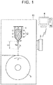
FIG 1 is a schematic view illustrating a molten metal temperature control method according to one aspect of the present invention; -
FIG 2 is a view showing a pressure-versus-spheroidization distance correlation graph; -
FIG 3 is a view showing a temperature-versus-spheroidization distance correlation graph; -
FIG 4 is a view illustrating the molten metal temperature control method based on the temperature-versus-spheroidization distance correlation graph; and -
FIG. 5 is a flowchart illustrating the molten metal temperature control method according to one aspect of the present invention. - In the following, an embodiment of a molten metal temperature control method of the present invention will be described with reference to the drawings.
-
FIG. 1 is a schematic view illustrating the molten metal temperature control method of the present invention;FIG. 2 is a view showing a pressure-versus-spheroidization distance correlation graph;FIG. 3 is a view showing a temperature-versus-spheroidization distance correlation graph; andFIG. 4 is a view illustrating the molten metal temperature control method based on the temperature-versus-spheroidization distance correlation graph.FIG. 5 is a flowchart illustrating the molten metal temperature control method of the present invention. - As shown in
FIG. 1 , acrucible 1 having anozzle 1a with a predetermined diameter φ provided at the bottom, a high-frequency coil 2 disposed around thecrucible 1, and arotating roll 5 that is disposed under thenozzle 1 a and quenches droplets of a molten metal falling thereon are disposed inside achamber 10, and a quenched ribbon that is a material for a rare-earth magnet is manufactured inside thechamber 10 by the melt spinning method. - As the high-
frequency coil 2 is activated, an alloy used for forming a quenched ribbon that is a material for a rare-earth magnet is melted by high-frequency induction heating and the molten metal Y is generated inside thecrucible 1. The inside of thechamber 10 is kept at a reduced pressure not higher than 50 Pa, for example, while the inside of thecrucible 1 is placed in an Ar-gas atmosphere. The molten metal Y is pressed with an Ar gas at a pressure P not higher than 100 kPa, for example, to discharge the molten metal Y downward (in the X-direction) through thenozzle 1a. - The molten metal Y having been discharged downward from the
nozzle 1a first stretches in the form of a stream over a predetermined spheroidization distance Lc, and turns into droplets down beyond the spheroidization distance Lc. These droplets fall on the top of thecopper rotating roll 5 that is rotating (in the Z-direction), where the droplets are quenched and a quenched ribbon resulting from quenching is jetted in a direction tangential to the top of therotating roll 5. The spheroidization distance Lc refers to a distance traveled by the molten metal before droplets are formed based on the Plateau-Rayleigh instability theory. - Here, the quenched ribbon is composed of an RE-Fe-B-based main phase (RE: at least one of Nd and Pr) and an RE-X alloy (X: a metal element containing no heavy rare-earth element) present around the main phase, and in the case of a nanocrystal structure, for example, the quenched ribbon is composed of a main phase of crystal grains not larger than 200 nm.
- The Nd-X alloy constituting the grain boundary phase is an alloy composed of Nd and at least one of Co, Fe, Ga, Cu, Al, etc., and, for example, composed of any one kind of Nd-Co, Nd-Fe, Nd-Ga, Nd-Co-Fe, and Nd-Co-Fe-Ga, or is a mixture of at least two of Nd-Co, Nd-Fe, Nd-Ga, Nd-Co-Fe, and Nd-Co-Fe-Ga, and the Nd-X alloy is in an Nd-rich state.
- Although not shown, a flow passage is disposed inside the
chamber 10 in a direction in which the quenched ribbon is jetted, and the jetted quenched ribbon passes through the flow passage and is collected in a collection box. - To measure the spheroidization distance Lc of the molten metal Y under the
crucible 1, animaging device 3, such as a CCD camera, is disposed at a position obliquely under thecrucible 1, and image data is transmitted to acomputer 4 by wired or wireless transmission. - Here, the present inventors have found that there is a linear correlation between the spheroidization distance Lc and a pressure acting on the molten metal Y inside the crucible 1 (pressure P in
FIG. 1 ).FIG. 2 shows the pressure-versus-spheroidization distance correlation graph in three cases where the temperature of the molten metal Y is 1300°C, 1400°C, and 1500°C, respectively, and the nozzle diameter is the predetermined diameter φ. On the creation of the graph, the pressure-versus-spheroidization distance correlation graph at each temperature is obtained on the following conditions: the vacuum degree inside thechamber 10 is not higher than 50 Pa; the Ar-gas pressure inside thecrucible 1 is within the range of 0 to 100 kPa; the nozzle diameter is 0.6 to 1.0 mm; and the alloy weight is 4 kg. -
FIG. 3 shows the temperature-versus-spheroidization distance correlation graph created on the basis ofFIG. 2 . From the temperature-versus-spheroidization distance correlation graph shown inFIG. 3 and specified by the present inventors, it can be seen that the spheroidization distance increases with the increasing temperature, and that the correlation graph is a curved graph that reaches an inflection point at around 1400°C. It can also be seen that the spheroidization distance increases as the pressure acting on the molten metal Y inside thecrucible 1 decreases. -
FIG. 4 is a view schematically showing the temperature-versus-spheroidization distance correlation graph ofFIG. 3 , and illustrating the molten metal temperature control method of the present invention. - The molten metal temperature control method of the present invention involves measuring the spheroidization distance of the molten metal instead of the temperature and the viscosity of the molten metal that are difficult to directly measure, plotting the measured spheroidization distance on the temperature-versus-spheroidization distance correlation graph shown in
FIG. 4 , specifying the temperature corresponding to that spheroidization distance, and controlling the specified temperature so as to be within a preset proper temperature range (predetermined temperature range). - The molten metal temperature control method further involves examining in advance various temperatures of the molten metal Y inside the crucible 1 (and the spheroidization distances Lc corresponding to the respective temperatures of the molten metal Y) and the quality of a quenched ribbon produced from the molten metal Y at the respective temperatures, and setting, as the proper temperature range, an optimal temperature range of the molten metal Y within which a quenched ribbon of desired quality is produced.
- In
FIG. 4 , the lower limit and the upper limit of the proper temperature range of the molten metal Y are Ta°C and Tb°C, respectively, and the spheroidization distances corresponding to the temperatures Ta and Tb are La cm and Lb cm, respectively. - If a temperature Tc corresponding to the measured spheroidization distance Lc is within the proper temperature range of Ta to Tb, it is regarded that a quenched ribbon of desired quality can be produced, and control is performed so as to maintain the temperature of the molten metal Y inside the
crucible 1 as it is. - On the other hand, if the temperature Tc corresponding to the measured spheroidization distance Lc is below the lower limit Ta°C, control is executed so as to raise the temperature of the molten metal Y inside the
crucible 1 by further heating thecrucible 1 with the high-frequency coil 2, and control is executed such that the temperature Tc corresponding to the measured spheroidization distance Lc falls within the proper temperature range of Ta to Tb. - Conversely, if the temperature Tc corresponding to the measured spheroidization distance Lc is above the upper limit Tb°C, control is executed so as to lower the temperature of the molten metal Y inside the
crucible 1 by stopping the heating of thecrucible 1 with the high-frequency coil 2, or cooling thecrucible 1 in addition to stopping the heating, and control is executed such that the temperature Tc corresponding to the measured spheroidization distance Lc falls within the proper temperature range of Ta to Tb. - Inside the
computer 4 shown inFIG. 1 , the temperature-versus-spheroidization distance correlation graphs corresponding to various pressures are stored. Data on the spheroidization distance Lc imaged by theimaging device 3 is transmitted to thecomputer 4, and the spheroidization distance Lc is plotted on the temperature-versus-spheroidization distance correlation graph inside thecomputer 4. Then, the temperature Tc corresponding to that spheroidization distance Lc is specified, and it is determined whether or not the specified temperature Tc is within the proper temperature range of Ta to Tb. - Here, the molten metal temperature control method of the present invention will be described with reference to the flowchart of
FIG. 5 . - First, a temperature-versus-spheroidization distance correlation graph is created for each of various pressures that can be set inside the
crucible 1 having the nozzle with the predetermined diameter φ, and a proper temperature range of the molten metal Y is set in each correlation graph (step S1) (the end of a first step of the molten metal temperature control method). Since the temperature-versus-spheroidization distance correlation graph varies with different nozzle diameters φ, if there are a plurality ofcrucibles 1 with different nozzle diameters, the temperature-versus-spheroidization distance correlation graphs for the respective pressures are created for eachcrucible 1. - Next, the heating conditions of the molten metal Y inside the
crucible 1 are set (step S2). In this step of setting the heating conditions, it is preferable that the heating conditions are set such that the temperature of the molten metal Y discharged from thenozzle 1a falls within the set proper temperature range of Ta to Tb. However, the initial heating conditions do not have to be set exactly. This is because, as will be described later, if the specified temperature of the molten metal Y is not within the proper temperature range of Ta to Tb, measures are taken to bring the specified temperature into the proper temperature range of Ta to Tb by executing the control of raising or lowering the temperature of the molten metal Y inside thecrucible 1. - When the heating conditions have been set, the heating of the
crucible 1 and the molten metal Y inside thecrucible 1 with the high-frequency coil 2 is started (step S3). - Prior to the start of heating, or after the start of heating, the inside of the
chamber 10 is depressurized and the inside of thecrucible 1 is placed in an Ar-gas atmosphere, and the pressure of the Ar gas, i.e., the pressure P acting on the molten metal Y (discharge pressure) is set (step S4). Then, the discharge of the molten metal Y from thenozzle 1a is started (step S6). - A temperature-versus-spheroidization distance correlation graph corresponding to the set discharge pressure is selected (step S5), and the molten metal temperature is controlled on the basis of the selected temperature-versus-spheroidization distance correlation graph.
- After the discharge of the molten metal Y is started, the spheroidization distance Lc of the molten metal Y is measured (step S7). The measured spheroidization distance Lc is transmitted to the
computer 4, and the spheroidization distance Lc is plotted on the temperature-versus-spheroidization distance correlation graph already selected inside thecomputer 4, and the molten metal temperature Tc corresponding to the spheroidization distance Lc is specified (step S8) (the end of a second step of the molten metal temperature control method). - It is examined inside the
computer 4 whether or not the specified molten metal temperature Tc is within the proper temperature range of Ta to Tb (step S9). Although not shown, a determination unit, a CPU, a RAM, a ROM, a correlation graph storage unit, etc. are connected with one another through buses inside thecomputer 4, and the determination unit determines whether or not the molten metal temperature Tc is within the proper temperature range of Ta to Tb. - If the molten metal temperature Tc is within the proper temperature range of Ta to Tb, no change is made to the conditions, such as the heating conditions and the pressure condition of the Ar gas (step S10), and the discharge of the molten metal Y onto the
rotating roll 5 is continued with the current temperature of the molten metal Y maintained. Then, a quenched ribbon formed by the molten metal Y being quenched on the surface of therotating roll 5 is selected as the material for the rare-earth magnet (step S11). - On the other hand, if the molten metal temperature Tc is lower than the lower limit Ta of the proper temperature range of Ta to Tb (step S12), the molten metal temperature inside the
crucible 1 is raised with the high-frequency coil 2 (step S13), and the molten metal Y is discharged to re-measure the spheroidization distance Lc (step S7). - The above steps are repeated until the molten metal temperature Tc corresponding to the re-measured spheroidization distance Lc falls within the proper temperature range of Ta to Tb, and at a point when the temperature of the molten metal Y falls within the proper temperature range of Ta to Tb, the temperature of the molten metal Y is maintained and the discharge of the molten metal Y onto the
rotating roll 5 is continued. - If the molten metal temperature Tc is higher than the upper limit Tb of the proper temperature range of Ta to Tb (step S14), heating with the high-
frequency coil 2 is stopped to lower the molten metal temperature inside the crucible 1 (step S15), and the molten metal Y is discharged to re-measure the spheroidization distance Lc (step S7). - In this case, too, the above steps are repeated until the molten metal temperature Tc corresponding to the re-measured spheroidization distance Lc falls within the proper temperature range of Ta to Tb, and at a point when the temperature of the molten metal Y falls within the proper temperature range of Ta to Tb, the temperature of the molten metal Y is maintained and the discharge of the molten metal Y onto the
rotating roll 5 is continued (the end of a third step of the molten metal temperature control method). - According to the shown molten metal temperature control method, it is possible to accurately specify the temperature of the molten metal that is difficult to directly measure, and obtain a quenched ribbon of desired quality by controlling the specified temperature so as to be within the proper temperature range.
- While the embodiment of the present invention has been described in detail using the drawings, the specific configuration is not limited to that of the embodiment, and any design changes etc. made within the scope of the present invention as defined by the claims shall be included in the invention.
Claims (6)
- A molten metal temperature control method comprising:with respect to relations among a spheroidization distance (Lc) traveled by a molten metal (Y) of an alloy discharged from a nozzle (1a), with a predetermined diameter (φ), of a crucible (1) from a nozzle tip to a position where the molten metal (Y) turns into droplets, a temperature of the molten metal (Y) inside the crucible (1), and a pressure (P) acting on the molten metal (Y) inside the crucible (1), obtaining in advance a relation between the temperature and the spheroidization distance (Lc) at a predetermined pressure that is the pressure (P) acting on the molten metal (Y) inside the crucible (1), and setting a predetermined temperature range (Ta to Tb) of the temperature;measuring the spheroidization distance (Lc) when discharging the molten metal (Y) from the crucible (1) at the predetermined pressure, and specifying the temperature (Tc) corresponding to the measured spheroidization distance (Lc); andcomparing the specified temperature (Tc) and the predetermined temperature range (Ta to Tb), and when the specified temperature (Tc) is outside the predetermined temperature range (Ta to Tb), controlling the specified temperature (Tc) so as to be within the predetermined temperature range (Ta to Tb) by adjusting the temperature inside the crucible (1).
- The molten metal temperature control method according to claim 1, wherein the spheroidization distance (Lc) is a distance traveled by the molten metal (Y) before droplets are formed based on the Plateau-Rayleigh instability theory.
- The molten metal temperature control method according to claim 1 or 2, wherein the molten metal (Y) is an alloy used for forming a quenched ribbon that is a material for a rare-earth magnet.
- The molten metal temperature control method according to claim 3, wherein the quenched ribbon includes an RE-Fe-B-based main phase, where RE is at least one of Nd and Pr, and a grain boundary phase of an RE-X alloy, where X is a metal element containing no heavy rare-earth element, present around the main phase.
- The molten metal temperature control method according to claim 4, wherein the RE-X alloy constituting the grain boundary phase is any one type of Nd-Co, Nd-Fe, Nd-Ga, Nd-Co-Fe, and Nd-Co-Fe-Ga, is or a mixture of at least two of Nd-Co, Nd-Fe, Nd-Ga, Nd-Co-Fe, and Nd-Co-Fe-Ga, and
the RE-X alloy is in an Nd-rich state. - A molten metal temperature control method comprising:a first step of [page 3, line 19] obtaining in advance a relation between a temperature and a spheroidization distance (Lc) at a predetermined pressure and setting a predetermined temperature range (Ta to Tb) of the temperature, whereinthe spheroidization distance (Lc) is a distance traveled by a molten metal (Y) of an alloy discharged from a nozzle (1a), with a predetermined diameter (φ), of a crucible (1) from a nozzle tip to a position where the molten metal (Y) turns into droplets based on the Plateau-Rayleigh instability theory,the temperature is the temperature of the molten metal (Y) inside the crucible (1), andthe predetermined pressure is the pressure (P) acting on the molten metal (Y) inside the crucible (1);a second step of [page 3, line 26] measuring the spheroidization distance (Lc) when discharging the molten metal (Y) from the crucible (1) at the predetermined pressure, and specifying the temperature (Tc) corresponding to the measured spheroidization distance (Lc); anda third step of [page 3, line 29] comparing the specified temperature (Tc) and the predetermined temperature range (Ta to Tb), and when the specified temperature (Tc) is outside the predetermined temperature range (Ta to Tb), controlling the specified temperature (Tc) so as to be within the predetermined temperature range (Ta to Tb) by adjusting the temperature inside the crucible (1) by heating, stopping the heating or cooling the crucible [page 5, lines 26 and 27 as well as page 10, line 25 and page 11, lines 2 and 3].
Applications Claiming Priority (1)
| Application Number | Priority Date | Filing Date | Title |
|---|---|---|---|
| JP2015202284A JP6296036B2 (en) | 2015-10-13 | 2015-10-13 | Molten metal temperature control method |
Publications (2)
| Publication Number | Publication Date |
|---|---|
| EP3156149A1 true EP3156149A1 (en) | 2017-04-19 |
| EP3156149B1 EP3156149B1 (en) | 2018-11-28 |
Family
ID=57256047
Family Applications (1)
| Application Number | Title | Priority Date | Filing Date |
|---|---|---|---|
| EP16193268.6A Not-in-force EP3156149B1 (en) | 2015-10-13 | 2016-10-11 | Molten metal temperature control method |
Country Status (4)
| Country | Link |
|---|---|
| US (1) | US10393440B2 (en) |
| EP (1) | EP3156149B1 (en) |
| JP (1) | JP6296036B2 (en) |
| CN (1) | CN106563779B (en) |
Families Citing this family (4)
| Publication number | Priority date | Publication date | Assignee | Title |
|---|---|---|---|---|
| EP3479926A1 (en) | 2017-11-06 | 2019-05-08 | Technische Universität Graz | Method for modifying the particle shape and the particle size distribution of aluminum-based powders |
| CN108168326A (en) * | 2017-12-14 | 2018-06-15 | 合肥金星机电科技发展有限公司 | The field visualized monitoring method of kiln temperature |
| CN110634279B (en) * | 2019-09-09 | 2020-10-09 | 浙江永贵电器股份有限公司 | Non-contact self-learning severe environment temperature collector based on AVR single chip microcomputer |
| WO2021138609A1 (en) * | 2019-12-31 | 2021-07-08 | Crystal Technologies LLC | Singulated liquid metal droplet generator |
Citations (5)
| Publication number | Priority date | Publication date | Assignee | Title |
|---|---|---|---|---|
| JPH01153938A (en) | 1987-12-10 | 1989-06-16 | Babcock Hitachi Kk | Instrument for measuring on-line viscosity of slurry |
| JPH0245730A (en) | 1988-08-08 | 1990-02-15 | Babcock Hitachi Kk | On-line viscosity measuring instrument for slurry fuel |
| EP1045402A2 (en) * | 1999-04-15 | 2000-10-18 | Hitachi Metals, Ltd. | Soft magnetic alloy strip, manufacturing method and use thereof |
| JP2003320442A (en) | 2002-04-30 | 2003-11-11 | Sumitomo Special Metals Co Ltd | Method for producing rapid-cooled alloy |
| WO2004092428A2 (en) * | 2003-04-14 | 2004-10-28 | Liquidmetal Technologies, Inc. | Continuous casting of bulk solidifying amorphous alloys |
Family Cites Families (5)
| Publication number | Priority date | Publication date | Assignee | Title |
|---|---|---|---|---|
| DE4022648C2 (en) * | 1990-07-17 | 1994-01-27 | Nukem Gmbh | Method and device for producing spherical particles from a liquid phase |
| US5266098A (en) * | 1992-01-07 | 1993-11-30 | Massachusetts Institute Of Technology | Production of charged uniformly sized metal droplets |
| JP2005118803A (en) * | 2003-10-15 | 2005-05-12 | Toyota Motor Corp | Metal sheet manufacturing apparatus and manufacturing method |
| EP2676749A4 (en) * | 2011-02-14 | 2015-04-08 | Nippon Steel & Sumitomo Metal Corp | DEVICE FOR MEASURING THE TEMPERATURE OF THE SURFACE OF CAST SLABS USED IN A CONTINUOUS CASTING MACHINE |
| CN103878329B (en) * | 2014-02-19 | 2016-10-05 | 安泰科技股份有限公司 | The nozzle heating device prepared for amorphous band and temperature control system and method |
-
2015
- 2015-10-13 JP JP2015202284A patent/JP6296036B2/en active Active
-
2016
- 2016-10-11 US US15/290,539 patent/US10393440B2/en active Active
- 2016-10-11 CN CN201610886166.7A patent/CN106563779B/en active Active
- 2016-10-11 EP EP16193268.6A patent/EP3156149B1/en not_active Not-in-force
Patent Citations (5)
| Publication number | Priority date | Publication date | Assignee | Title |
|---|---|---|---|---|
| JPH01153938A (en) | 1987-12-10 | 1989-06-16 | Babcock Hitachi Kk | Instrument for measuring on-line viscosity of slurry |
| JPH0245730A (en) | 1988-08-08 | 1990-02-15 | Babcock Hitachi Kk | On-line viscosity measuring instrument for slurry fuel |
| EP1045402A2 (en) * | 1999-04-15 | 2000-10-18 | Hitachi Metals, Ltd. | Soft magnetic alloy strip, manufacturing method and use thereof |
| JP2003320442A (en) | 2002-04-30 | 2003-11-11 | Sumitomo Special Metals Co Ltd | Method for producing rapid-cooled alloy |
| WO2004092428A2 (en) * | 2003-04-14 | 2004-10-28 | Liquidmetal Technologies, Inc. | Continuous casting of bulk solidifying amorphous alloys |
Also Published As
| Publication number | Publication date |
|---|---|
| JP6296036B2 (en) | 2018-03-20 |
| US10393440B2 (en) | 2019-08-27 |
| CN106563779A (en) | 2017-04-19 |
| CN106563779B (en) | 2018-10-12 |
| JP2017074596A (en) | 2017-04-20 |
| US20170102185A1 (en) | 2017-04-13 |
| EP3156149B1 (en) | 2018-11-28 |
Similar Documents
| Publication | Publication Date | Title |
|---|---|---|
| EP3156149B1 (en) | Molten metal temperature control method | |
| JPH1121120A (en) | Method and apparatus for manufacturing polycrystalline semiconductor | |
| US20090321996A1 (en) | Silicon Electro-Magnetic Casting Apparatus and Operation Method of the Same | |
| JP4875229B2 (en) | Silica glass crucible | |
| TW446766B (en) | Method and apparatus for accurately pulling a crystal | |
| CN111842814B (en) | Vacuum precision casting furnace, temperature measuring device and temperature measuring method of vacuum precision casting furnace | |
| Tamura et al. | Influencing factors on the amorphous phase formation in Fe–7.7 at% Sm alloys solidified by high-speed melt spinning | |
| JP5877812B2 (en) | Method for producing SiC single crystal | |
| KR101791652B1 (en) | METHOD FOR MANUFACTURING SiC SINGLE CRYSTAL | |
| US5067551A (en) | Method for manufacturing alloy rod having giant magnetostriction | |
| JP2002326888A (en) | Device for manufacturing semiconductor single crystal and method for manufacturing silicon single crystal using the same | |
| JP2026034507A (en) | silicon single crystal | |
| KR102422843B1 (en) | Method of estimating oxygen concentration of silicon single crystal and manufacturing method of silicon single crystal | |
| CN212371130U (en) | Vacuum precision casting furnace, temperature measuring device of vacuum precision casting furnace | |
| JP2880092B2 (en) | Single crystal manufacturing method | |
| JP2003320442A (en) | Method for producing rapid-cooled alloy | |
| JP5125983B2 (en) | Method for producing silicon single crystal | |
| JP2008063218A (en) | Method and apparatus for manufacturing a tube | |
| KR102456026B1 (en) | Apparatus for measurement of glass forming ability and measurement methods of using the same | |
| US5485876A (en) | Process for producing metal material with excellent mechanical properties | |
| JP3098699B2 (en) | Supply method of molten alloy for manufacturing amorphous alloy ribbon and stopper for controlling supply amount | |
| JP5877813B2 (en) | Method for producing SiC single crystal | |
| JP2026001908A (en) | Silicon single crystal manufacturing method | |
| JP3098698B2 (en) | Supply method of molten alloy for production of amorphous alloy ribbon | |
| JP6221598B2 (en) | Method for producing alloy ribbon for rare earth magnet |
Legal Events
| Date | Code | Title | Description |
|---|---|---|---|
| PUAI | Public reference made under article 153(3) epc to a published international application that has entered the european phase |
Free format text: ORIGINAL CODE: 0009012 |
|
| STAA | Information on the status of an ep patent application or granted ep patent |
Free format text: STATUS: REQUEST FOR EXAMINATION WAS MADE |
|
| 17P | Request for examination filed |
Effective date: 20161011 |
|
| AK | Designated contracting states |
Kind code of ref document: A1 Designated state(s): AL AT BE BG CH CY CZ DE DK EE ES FI FR GB GR HR HU IE IS IT LI LT LU LV MC MK MT NL NO PL PT RO RS SE SI SK SM TR |
|
| AX | Request for extension of the european patent |
Extension state: BA ME |
|
| STAA | Information on the status of an ep patent application or granted ep patent |
Free format text: STATUS: EXAMINATION IS IN PROGRESS |
|
| 17Q | First examination report despatched |
Effective date: 20171018 |
|
| GRAP | Despatch of communication of intention to grant a patent |
Free format text: ORIGINAL CODE: EPIDOSNIGR1 |
|
| STAA | Information on the status of an ep patent application or granted ep patent |
Free format text: STATUS: GRANT OF PATENT IS INTENDED |
|
| INTG | Intention to grant announced |
Effective date: 20180517 |
|
| GRAS | Grant fee paid |
Free format text: ORIGINAL CODE: EPIDOSNIGR3 |
|
| GRAA | (expected) grant |
Free format text: ORIGINAL CODE: 0009210 |
|
| STAA | Information on the status of an ep patent application or granted ep patent |
Free format text: STATUS: THE PATENT HAS BEEN GRANTED |
|
| AK | Designated contracting states |
Kind code of ref document: B1 Designated state(s): AL AT BE BG CH CY CZ DE DK EE ES FI FR GB GR HR HU IE IS IT LI LT LU LV MC MK MT NL NO PL PT RO RS SE SI SK SM TR |
|
| REG | Reference to a national code |
Ref country code: CH Ref legal event code: EP |
|
| REG | Reference to a national code |
Ref country code: AT Ref legal event code: REF Ref document number: 1069639 Country of ref document: AT Kind code of ref document: T Effective date: 20181215 |
|
| REG | Reference to a national code |
Ref country code: IE Ref legal event code: FG4D |
|
| REG | Reference to a national code |
Ref country code: DE Ref legal event code: R096 Ref document number: 602016007563 Country of ref document: DE |
|
| REG | Reference to a national code |
Ref country code: DE Ref legal event code: R084 Ref document number: 602016007563 Country of ref document: DE |
|
| REG | Reference to a national code |
Ref country code: NL Ref legal event code: MP Effective date: 20181128 |
|
| REG | Reference to a national code |
Ref country code: LT Ref legal event code: MG4D |
|
| REG | Reference to a national code |
Ref country code: AT Ref legal event code: MK05 Ref document number: 1069639 Country of ref document: AT Kind code of ref document: T Effective date: 20181128 |
|
| PG25 | Lapsed in a contracting state [announced via postgrant information from national office to epo] |
Ref country code: NO Free format text: LAPSE BECAUSE OF FAILURE TO SUBMIT A TRANSLATION OF THE DESCRIPTION OR TO PAY THE FEE WITHIN THE PRESCRIBED TIME-LIMIT Effective date: 20190228 Ref country code: LT Free format text: LAPSE BECAUSE OF FAILURE TO SUBMIT A TRANSLATION OF THE DESCRIPTION OR TO PAY THE FEE WITHIN THE PRESCRIBED TIME-LIMIT Effective date: 20181128 Ref country code: HR Free format text: LAPSE BECAUSE OF FAILURE TO SUBMIT A TRANSLATION OF THE DESCRIPTION OR TO PAY THE FEE WITHIN THE PRESCRIBED TIME-LIMIT Effective date: 20181128 Ref country code: IS Free format text: LAPSE BECAUSE OF FAILURE TO SUBMIT A TRANSLATION OF THE DESCRIPTION OR TO PAY THE FEE WITHIN THE PRESCRIBED TIME-LIMIT Effective date: 20190328 Ref country code: LV Free format text: LAPSE BECAUSE OF FAILURE TO SUBMIT A TRANSLATION OF THE DESCRIPTION OR TO PAY THE FEE WITHIN THE PRESCRIBED TIME-LIMIT Effective date: 20181128 Ref country code: ES Free format text: LAPSE BECAUSE OF FAILURE TO SUBMIT A TRANSLATION OF THE DESCRIPTION OR TO PAY THE FEE WITHIN THE PRESCRIBED TIME-LIMIT Effective date: 20181128 Ref country code: BG Free format text: LAPSE BECAUSE OF FAILURE TO SUBMIT A TRANSLATION OF THE DESCRIPTION OR TO PAY THE FEE WITHIN THE PRESCRIBED TIME-LIMIT Effective date: 20190228 Ref country code: AT Free format text: LAPSE BECAUSE OF FAILURE TO SUBMIT A TRANSLATION OF THE DESCRIPTION OR TO PAY THE FEE WITHIN THE PRESCRIBED TIME-LIMIT Effective date: 20181128 Ref country code: FI Free format text: LAPSE BECAUSE OF FAILURE TO SUBMIT A TRANSLATION OF THE DESCRIPTION OR TO PAY THE FEE WITHIN THE PRESCRIBED TIME-LIMIT Effective date: 20181128 |
|
| PG25 | Lapsed in a contracting state [announced via postgrant information from national office to epo] |
Ref country code: GR Free format text: LAPSE BECAUSE OF FAILURE TO SUBMIT A TRANSLATION OF THE DESCRIPTION OR TO PAY THE FEE WITHIN THE PRESCRIBED TIME-LIMIT Effective date: 20190301 Ref country code: RS Free format text: LAPSE BECAUSE OF FAILURE TO SUBMIT A TRANSLATION OF THE DESCRIPTION OR TO PAY THE FEE WITHIN THE PRESCRIBED TIME-LIMIT Effective date: 20181128 Ref country code: AL Free format text: LAPSE BECAUSE OF FAILURE TO SUBMIT A TRANSLATION OF THE DESCRIPTION OR TO PAY THE FEE WITHIN THE PRESCRIBED TIME-LIMIT Effective date: 20181128 Ref country code: SE Free format text: LAPSE BECAUSE OF FAILURE TO SUBMIT A TRANSLATION OF THE DESCRIPTION OR TO PAY THE FEE WITHIN THE PRESCRIBED TIME-LIMIT Effective date: 20181128 Ref country code: PT Free format text: LAPSE BECAUSE OF FAILURE TO SUBMIT A TRANSLATION OF THE DESCRIPTION OR TO PAY THE FEE WITHIN THE PRESCRIBED TIME-LIMIT Effective date: 20190328 |
|
| PG25 | Lapsed in a contracting state [announced via postgrant information from national office to epo] |
Ref country code: NL Free format text: LAPSE BECAUSE OF FAILURE TO SUBMIT A TRANSLATION OF THE DESCRIPTION OR TO PAY THE FEE WITHIN THE PRESCRIBED TIME-LIMIT Effective date: 20181128 |
|
| PG25 | Lapsed in a contracting state [announced via postgrant information from national office to epo] |
Ref country code: IT Free format text: LAPSE BECAUSE OF FAILURE TO SUBMIT A TRANSLATION OF THE DESCRIPTION OR TO PAY THE FEE WITHIN THE PRESCRIBED TIME-LIMIT Effective date: 20181128 Ref country code: DK Free format text: LAPSE BECAUSE OF FAILURE TO SUBMIT A TRANSLATION OF THE DESCRIPTION OR TO PAY THE FEE WITHIN THE PRESCRIBED TIME-LIMIT Effective date: 20181128 Ref country code: CZ Free format text: LAPSE BECAUSE OF FAILURE TO SUBMIT A TRANSLATION OF THE DESCRIPTION OR TO PAY THE FEE WITHIN THE PRESCRIBED TIME-LIMIT Effective date: 20181128 Ref country code: PL Free format text: LAPSE BECAUSE OF FAILURE TO SUBMIT A TRANSLATION OF THE DESCRIPTION OR TO PAY THE FEE WITHIN THE PRESCRIBED TIME-LIMIT Effective date: 20181128 |
|
| REG | Reference to a national code |
Ref country code: DE Ref legal event code: R097 Ref document number: 602016007563 Country of ref document: DE |
|
| PG25 | Lapsed in a contracting state [announced via postgrant information from national office to epo] |
Ref country code: SK Free format text: LAPSE BECAUSE OF FAILURE TO SUBMIT A TRANSLATION OF THE DESCRIPTION OR TO PAY THE FEE WITHIN THE PRESCRIBED TIME-LIMIT Effective date: 20181128 Ref country code: RO Free format text: LAPSE BECAUSE OF FAILURE TO SUBMIT A TRANSLATION OF THE DESCRIPTION OR TO PAY THE FEE WITHIN THE PRESCRIBED TIME-LIMIT Effective date: 20181128 Ref country code: EE Free format text: LAPSE BECAUSE OF FAILURE TO SUBMIT A TRANSLATION OF THE DESCRIPTION OR TO PAY THE FEE WITHIN THE PRESCRIBED TIME-LIMIT Effective date: 20181128 Ref country code: SM Free format text: LAPSE BECAUSE OF FAILURE TO SUBMIT A TRANSLATION OF THE DESCRIPTION OR TO PAY THE FEE WITHIN THE PRESCRIBED TIME-LIMIT Effective date: 20181128 |
|
| PLBE | No opposition filed within time limit |
Free format text: ORIGINAL CODE: 0009261 |
|
| STAA | Information on the status of an ep patent application or granted ep patent |
Free format text: STATUS: NO OPPOSITION FILED WITHIN TIME LIMIT |
|
| PG25 | Lapsed in a contracting state [announced via postgrant information from national office to epo] |
Ref country code: SI Free format text: LAPSE BECAUSE OF FAILURE TO SUBMIT A TRANSLATION OF THE DESCRIPTION OR TO PAY THE FEE WITHIN THE PRESCRIBED TIME-LIMIT Effective date: 20181128 |
|
| 26N | No opposition filed |
Effective date: 20190829 |
|
| PG25 | Lapsed in a contracting state [announced via postgrant information from national office to epo] |
Ref country code: TR Free format text: LAPSE BECAUSE OF FAILURE TO SUBMIT A TRANSLATION OF THE DESCRIPTION OR TO PAY THE FEE WITHIN THE PRESCRIBED TIME-LIMIT Effective date: 20181128 |
|
| PG25 | Lapsed in a contracting state [announced via postgrant information from national office to epo] |
Ref country code: MC Free format text: LAPSE BECAUSE OF FAILURE TO SUBMIT A TRANSLATION OF THE DESCRIPTION OR TO PAY THE FEE WITHIN THE PRESCRIBED TIME-LIMIT Effective date: 20181128 |
|
| REG | Reference to a national code |
Ref country code: CH Ref legal event code: PL |
|
| PG25 | Lapsed in a contracting state [announced via postgrant information from national office to epo] |
Ref country code: LU Free format text: LAPSE BECAUSE OF NON-PAYMENT OF DUE FEES Effective date: 20191011 Ref country code: LI Free format text: LAPSE BECAUSE OF NON-PAYMENT OF DUE FEES Effective date: 20191031 Ref country code: CH Free format text: LAPSE BECAUSE OF NON-PAYMENT OF DUE FEES Effective date: 20191031 |
|
| REG | Reference to a national code |
Ref country code: BE Ref legal event code: MM Effective date: 20191031 |
|
| PG25 | Lapsed in a contracting state [announced via postgrant information from national office to epo] |
Ref country code: BE Free format text: LAPSE BECAUSE OF NON-PAYMENT OF DUE FEES Effective date: 20191031 |
|
| PG25 | Lapsed in a contracting state [announced via postgrant information from national office to epo] |
Ref country code: IE Free format text: LAPSE BECAUSE OF NON-PAYMENT OF DUE FEES Effective date: 20191011 Ref country code: FR Free format text: LAPSE BECAUSE OF NON-PAYMENT OF DUE FEES Effective date: 20191031 |
|
| PG25 | Lapsed in a contracting state [announced via postgrant information from national office to epo] |
Ref country code: CY Free format text: LAPSE BECAUSE OF FAILURE TO SUBMIT A TRANSLATION OF THE DESCRIPTION OR TO PAY THE FEE WITHIN THE PRESCRIBED TIME-LIMIT Effective date: 20181128 |
|
| GBPC | Gb: european patent ceased through non-payment of renewal fee |
Effective date: 20201011 |
|
| PG25 | Lapsed in a contracting state [announced via postgrant information from national office to epo] |
Ref country code: MT Free format text: LAPSE BECAUSE OF FAILURE TO SUBMIT A TRANSLATION OF THE DESCRIPTION OR TO PAY THE FEE WITHIN THE PRESCRIBED TIME-LIMIT Effective date: 20181128 Ref country code: HU Free format text: LAPSE BECAUSE OF FAILURE TO SUBMIT A TRANSLATION OF THE DESCRIPTION OR TO PAY THE FEE WITHIN THE PRESCRIBED TIME-LIMIT; INVALID AB INITIO Effective date: 20161011 |
|
| PG25 | Lapsed in a contracting state [announced via postgrant information from national office to epo] |
Ref country code: GB Free format text: LAPSE BECAUSE OF NON-PAYMENT OF DUE FEES Effective date: 20201011 |
|
| PG25 | Lapsed in a contracting state [announced via postgrant information from national office to epo] |
Ref country code: MK Free format text: LAPSE BECAUSE OF FAILURE TO SUBMIT A TRANSLATION OF THE DESCRIPTION OR TO PAY THE FEE WITHIN THE PRESCRIBED TIME-LIMIT Effective date: 20181128 |
|
| PGFP | Annual fee paid to national office [announced via postgrant information from national office to epo] |
Ref country code: DE Payment date: 20220831 Year of fee payment: 7 |
|
| P01 | Opt-out of the competence of the unified patent court (upc) registered |
Effective date: 20230427 |
|
| REG | Reference to a national code |
Ref country code: DE Ref legal event code: R119 Ref document number: 602016007563 Country of ref document: DE |
|
| PG25 | Lapsed in a contracting state [announced via postgrant information from national office to epo] |
Ref country code: DE Free format text: LAPSE BECAUSE OF NON-PAYMENT OF DUE FEES Effective date: 20240501 |