EP3154761B1 - Improved resin container for stereolithography - Google Patents
Improved resin container for stereolithography Download PDFInfo
- Publication number
- EP3154761B1 EP3154761B1 EP15731194.5A EP15731194A EP3154761B1 EP 3154761 B1 EP3154761 B1 EP 3154761B1 EP 15731194 A EP15731194 A EP 15731194A EP 3154761 B1 EP3154761 B1 EP 3154761B1
- Authority
- EP
- European Patent Office
- Prior art keywords
- actinically
- storage unit
- container
- resin
- lid
- Prior art date
- Legal status (The legal status is an assumption and is not a legal conclusion. Google has not performed a legal analysis and makes no representation as to the accuracy of the status listed.)
- Active
Links
Images





Classifications
-
- B—PERFORMING OPERATIONS; TRANSPORTING
- B29—WORKING OF PLASTICS; WORKING OF SUBSTANCES IN A PLASTIC STATE IN GENERAL
- B29C—SHAPING OR JOINING OF PLASTICS; SHAPING OF MATERIAL IN A PLASTIC STATE, NOT OTHERWISE PROVIDED FOR; AFTER-TREATMENT OF THE SHAPED PRODUCTS, e.g. REPAIRING
- B29C35/00—Heating, cooling or curing, e.g. crosslinking or vulcanising; Apparatus therefor
- B29C35/02—Heating or curing, e.g. crosslinking or vulcanizing during moulding, e.g. in a mould
- B29C35/08—Heating or curing, e.g. crosslinking or vulcanizing during moulding, e.g. in a mould by wave energy or particle radiation
- B29C35/0888—Heating or curing, e.g. crosslinking or vulcanizing during moulding, e.g. in a mould by wave energy or particle radiation using transparant moulds
-
- B—PERFORMING OPERATIONS; TRANSPORTING
- B29—WORKING OF PLASTICS; WORKING OF SUBSTANCES IN A PLASTIC STATE IN GENERAL
- B29C—SHAPING OR JOINING OF PLASTICS; SHAPING OF MATERIAL IN A PLASTIC STATE, NOT OTHERWISE PROVIDED FOR; AFTER-TREATMENT OF THE SHAPED PRODUCTS, e.g. REPAIRING
- B29C64/00—Additive manufacturing, i.e. manufacturing of three-dimensional [3D] objects by additive deposition, additive agglomeration or additive layering, e.g. by 3D printing, stereolithography or selective laser sintering
- B29C64/10—Processes of additive manufacturing
- B29C64/106—Processes of additive manufacturing using only liquids or viscous materials, e.g. depositing a continuous bead of viscous material
- B29C64/124—Processes of additive manufacturing using only liquids or viscous materials, e.g. depositing a continuous bead of viscous material using layers of liquid which are selectively solidified
- B29C64/129—Processes of additive manufacturing using only liquids or viscous materials, e.g. depositing a continuous bead of viscous material using layers of liquid which are selectively solidified characterised by the energy source therefor, e.g. by global irradiation combined with a mask
- B29C64/135—Processes of additive manufacturing using only liquids or viscous materials, e.g. depositing a continuous bead of viscous material using layers of liquid which are selectively solidified characterised by the energy source therefor, e.g. by global irradiation combined with a mask the energy source being concentrated, e.g. scanning lasers or focused light sources
-
- B—PERFORMING OPERATIONS; TRANSPORTING
- B29—WORKING OF PLASTICS; WORKING OF SUBSTANCES IN A PLASTIC STATE IN GENERAL
- B29C—SHAPING OR JOINING OF PLASTICS; SHAPING OF MATERIAL IN A PLASTIC STATE, NOT OTHERWISE PROVIDED FOR; AFTER-TREATMENT OF THE SHAPED PRODUCTS, e.g. REPAIRING
- B29C64/00—Additive manufacturing, i.e. manufacturing of three-dimensional [3D] objects by additive deposition, additive agglomeration or additive layering, e.g. by 3D printing, stereolithography or selective laser sintering
- B29C64/20—Apparatus for additive manufacturing; Details thereof or accessories therefor
- B29C64/255—Enclosures for the building material, e.g. powder containers
-
- B—PERFORMING OPERATIONS; TRANSPORTING
- B33—ADDITIVE MANUFACTURING TECHNOLOGY
- B33Y—ADDITIVE MANUFACTURING, i.e. MANUFACTURING OF THREE-DIMENSIONAL [3D] OBJECTS BY ADDITIVE DEPOSITION, ADDITIVE AGGLOMERATION OR ADDITIVE LAYERING, e.g. BY 3D PRINTING, STEREOLITHOGRAPHY OR SELECTIVE LASER SINTERING
- B33Y10/00—Processes of additive manufacturing
-
- B—PERFORMING OPERATIONS; TRANSPORTING
- B65—CONVEYING; PACKING; STORING; HANDLING THIN OR FILAMENTARY MATERIAL
- B65D—CONTAINERS FOR STORAGE OR TRANSPORT OF ARTICLES OR MATERIALS, e.g. BAGS, BARRELS, BOTTLES, BOXES, CANS, CARTONS, CRATES, DRUMS, JARS, TANKS, HOPPERS, FORWARDING CONTAINERS; ACCESSORIES, CLOSURES, OR FITTINGS THEREFOR; PACKAGING ELEMENTS; PACKAGES
- B65D11/00—Containers having bodies formed by interconnecting or uniting two or more rigid, or substantially rigid, components made wholly or mainly of plastics material
- B65D11/20—Details of walls made of plastics material
-
- B—PERFORMING OPERATIONS; TRANSPORTING
- B65—CONVEYING; PACKING; STORING; HANDLING THIN OR FILAMENTARY MATERIAL
- B65D—CONTAINERS FOR STORAGE OR TRANSPORT OF ARTICLES OR MATERIALS, e.g. BAGS, BARRELS, BOTTLES, BOXES, CANS, CARTONS, CRATES, DRUMS, JARS, TANKS, HOPPERS, FORWARDING CONTAINERS; ACCESSORIES, CLOSURES, OR FITTINGS THEREFOR; PACKAGING ELEMENTS; PACKAGES
- B65D47/00—Closures with filling and discharging, or with discharging, devices
- B65D47/04—Closures with discharging devices other than pumps
- B65D47/06—Closures with discharging devices other than pumps with pouring spouts or tubes; with discharge nozzles or passages
-
- B—PERFORMING OPERATIONS; TRANSPORTING
- B29—WORKING OF PLASTICS; WORKING OF SUBSTANCES IN A PLASTIC STATE IN GENERAL
- B29C—SHAPING OR JOINING OF PLASTICS; SHAPING OF MATERIAL IN A PLASTIC STATE, NOT OTHERWISE PROVIDED FOR; AFTER-TREATMENT OF THE SHAPED PRODUCTS, e.g. REPAIRING
- B29C35/00—Heating, cooling or curing, e.g. crosslinking or vulcanising; Apparatus therefor
- B29C35/02—Heating or curing, e.g. crosslinking or vulcanizing during moulding, e.g. in a mould
- B29C35/08—Heating or curing, e.g. crosslinking or vulcanizing during moulding, e.g. in a mould by wave energy or particle radiation
- B29C35/0805—Heating or curing, e.g. crosslinking or vulcanizing during moulding, e.g. in a mould by wave energy or particle radiation using electromagnetic radiation
- B29C2035/0833—Heating or curing, e.g. crosslinking or vulcanizing during moulding, e.g. in a mould by wave energy or particle radiation using electromagnetic radiation using actinic light
-
- B—PERFORMING OPERATIONS; TRANSPORTING
- B29—WORKING OF PLASTICS; WORKING OF SUBSTANCES IN A PLASTIC STATE IN GENERAL
- B29C—SHAPING OR JOINING OF PLASTICS; SHAPING OF MATERIAL IN A PLASTIC STATE, NOT OTHERWISE PROVIDED FOR; AFTER-TREATMENT OF THE SHAPED PRODUCTS, e.g. REPAIRING
- B29C31/00—Handling, e.g. feeding of the material to be shaped, storage of plastics material before moulding; Automation, i.e. automated handling lines in plastics processing plants, e.g. using manipulators or robots
- B29C31/02—Dispensing from vessels, e.g. hoppers
-
- B—PERFORMING OPERATIONS; TRANSPORTING
- B33—ADDITIVE MANUFACTURING TECHNOLOGY
- B33Y—ADDITIVE MANUFACTURING, i.e. MANUFACTURING OF THREE-DIMENSIONAL [3D] OBJECTS BY ADDITIVE DEPOSITION, ADDITIVE AGGLOMERATION OR ADDITIVE LAYERING, e.g. BY 3D PRINTING, STEREOLITHOGRAPHY OR SELECTIVE LASER SINTERING
- B33Y30/00—Apparatus for additive manufacturing; Details thereof or accessories therefor
Definitions
- the present invention relates generally to systems and methods for storing photopolymers used in additive fabrication, e.g., 3-dimensional printing.
- Additive fabrication e.g., 3-dimensional (3D) printing
- additive fabrication techniques may include stereo lithography, selective or fused deposition modeling, direct composite manufacturing, laminated object manufacturing, selective phase area deposition, multi-phase jet solidification, ballistic particle manufacturing, particle deposition, laser sintering or combinations thereof.
- Many additive fabrication techniques build parts by forming successive layers, which are typically cross-sections of the desired object. Typically each layer is formed such that it adheres to either a previously formed layer or a substrate upon which the object is built.
- solid objects are created by successively forming thin layers of a curable polymer resin, typically first onto a substrate and then one on top of another. Exposure to actinic radiation cures a thin layer of liquid resin, which causes it to harden and adhere to previously cured layers or the bottom surface of the build platform.
- Document WO_2014/016668 A1 discloses a cartridge container for a photocurable polymer having a bottom portion transparent to the curing radiation, and side walls opaque to this radiation.
- the container also comprises a top opening closable by an opaque lid.
- a storage unit according to the invention is defined in claim 1
- a method of additive fabrication according to the invention is defined in claim 13.
- Preferred embodiments are defined in the respective dependent claims.
- a storage unit comprising a photopolymer resin.
- the storage unit has a bottom face comprising at least one region of actinically transparent material that is actinically transparent with respect to the photopolymer resin.
- the storage unit also has at least one wall that extends upwards from the bottom face and that comprises at least one region of actinically opaque material that is actinically opaque with respect to the photopolymer resin.
- the storage unit has a lid comprising the actinically opaque material and removably connectable to the at least one wall.
- a method of additive fabrication includes producing at least one part from a photopolymer resin via one or more additive fabrication techniques, wherein the photopolymer resin is contained within a container that is a component of an additive fabrication device.
- the method further includes removing the container from the additive fabrication device and attaching a lid to the container.
- the lid and container comprise an actinically opaque material and comprise at least one region of actinically transparent material on a bottom face of the container.
- the present invention relates generally to systems and methods for storing photopolymers used in additive fabrication, e.g., 3-dimensional printing.
- the present invention is directed to methods and apparatuses which provide storage of photopolymers suitable for use in additive fabrication during periods in which the photopolymers are not actively being used for additive fabrication.
- the methods and apparatuses described herein may provide techniques for storing and transporting materials sensitive to actinic radiation in a format that can be easily loaded, unloaded, and used in material processing. As a result, sensitive materials may be more reliably used in a stereolithography process with reduced user error and increased convenience.
- solid objects may be created by successively curing layers of liquid resin via exposure of the resin to actinic radiation.
- actinic radiation capable of causing a liquid resin to partially or completely cure may be present in natural light and/or in other ambient radiation.
- the resin While during additive fabrication the resin may be shielded from unwanted sources of actinic radiation, unintentional exposure of a resin to actinic radiation may occur while the resin is not being used for additive fabrication.
- resin material may be stored in a vessel that is opaque to actinic radiation, yet unintentional exposure to actinic radiation may occur during loading and/or unloading of the resin material to and/or from the vessel. Such unintentional exposure may cause premature curing and/or other undesirable changes to properties of the resin.
- some resin may adhere to the vessel and/or the device's container.
- This resin may be partially or complete cured by ambient radiation, leading to a coating of a solid polymer on the vessel, which may inhibit subsequent use of the vessel.
- the inventors have recognized and appreciated that there are benefits to using a single storage unit for both storage of a resin material and for containing the resin material during additive fabrication. With such a configuration, it may be unnecessary to transfer resin material from the storage unit, leading to reduction of unintentional exposure and leading to easier use of the resin since the resin need not be poured from the storage unit into another vessel for fabrication.
- a single storage unit be used both for storage and during additive fabrication, it is desirable that the unit may be configured to be actinically opaque during storage yet include at least one actinically transparent region through which actinic radiation may be directed (e.g., to resin within the container) during additive fabrication.
- actinic radiation may be directed (e.g., to resin within the container) during additive fabrication.
- the inventors have recognized and appreciated that a storage unit may be configured in such a way by arranging an actinically transparent region of the unit such that during storage (which may include placing of a storage unit onto a surface and/or stacking of storage units) the actinically transparent region of the unit is substantially shielded from actinic radiation due to natural placement of the unit for storage.
- the storage unit includes a region that is transparent to actinic radiation such that the storage unit may be used in stereolithographic processes in which actinic radiation is supplied to the resin within the storage unit through that surface.
- the remainder of the storage unit is opaque to actinic radiation, and includes a removable lid that may be removed when the storage unit is installed within an additive fabrication device. Accordingly, the storage unit may be stored with the lid attached and also used without the lid directly as a component of an additive fabrication device. As such, it may become unnecessary to remove the resin from the storage container.
- the storage unit is shaped such that the actinically transparent region is covered by a table or other surface during storage of the resin (i.e., at times when additive fabrication is not being performed).
- the resin inside the storage unit may be substantially shielded from sources of actinic radiation exterior to the storage unit.
- the shielding surface is not present, and the actinically transparent region may be used to direct actinic radiation to resin located within the unit. Accordingly, a single storage unit may inhibit exposure of a resin to actinic radiation during storage using a combination of actinically opaque material and surfaces adjacent to the unit during storage, yet may allow actinic radiation to pass through the actinically transparent portion of the storage unit during additive fabrication.
- the storage unit includes a removable lid.
- the lid is opaque to actinic radiation and may be configured to be attached to a remainder of the storage unit when the storage unit is used for storage of resin, and is configured to be removed from the storage unit when the storage unit is installed within an additive fabrication device.
- the lid may be shaped so as to allow multiple storage units to be stacked on top of one another.
- the lid may include one or more portions shaped to mate with respective portions of a bottom side of a storage unit.
- the lid may also include one or more locking mechanisms configured to provide a seal or other tight fit between the lid and the remainder of the storage unit. In some cases, such a locking mechanism may include a portion on the lid and a portion on the remainder of the storage unit such that the two portions may mate and/or lock together to hold the lid in place.
- one or more portions of a bottom side of a storage unit that are actinically transparent is shaped to mate with respective portions of a lid of the storage unit.
- mating the two storage units via the respective portions may cause the portions of the lid to block actinic radiation that would otherwise pass through the actinically transparent portions of the bottom side of the storage unit.
- the storage units may be designed to stack in order to make the stack of storage units collectively actinically opaque, or to at least reduce the number of regions of the collection of storage units that are exposed to actinic radiation.
- storage units that are stackable as described above and that include an actinically transparent region on a bottom surface may be stacked such that the only actinically transparent region not covered by another storage unit is on the underside of the bottom storage unit of the stack.
- actinic radiation may cure the material, at least in part (e.g., it may harden the material to some extent).
- the actinic radiation may have no measurable effect on the material.
- Which effect(s) occur when a photopolymer is exposed to actinic radiation may depend, at least in part, on the wavelength(s) of radiation exhibited by the actinic radiation and/or the amplitude of the radiation at one or more of the wavelengths. For instance, since a given photopolymer may react to a particular wavelength, or wavelengths, of radiation, the effect of actinic radiation incident upon the photopolymer may depend upon which of the wavelengths, if any, are present in the actinic radiation.
- an actinically opaque material substantially attenuates (e.g., reduces the amplitude by 50-100%) the amplitude of at least one wavelength of radiation passing through the material (e.g., 405 nm wavelength light), wherein the at least one wavelength is associated with curing of at least one photopolymer. It may be the case that the same actinically opaque material does not substantially attenuate (though may attenuate to some degree) other wavelengths that could be used to cure a different photopolymer.
- a material may be considered actinically opaque if the material is configured to substantially attenuate the transmission of at least one wavelength that is capable of curing a particular photopolymer, or particular photopolymers (though may not substantially attenuate other wavelengths that are capable of curing a different photopolymer).
- an actinically transparent material does not substantially attenuate (e.g., reduces the amplitude by less than 50%) the amplitude of at least one wavelength of radiation passing through the material (e.g., 405 nm wavelength light), wherein the at least one wavelength is associated with curing of at least one photopolymer.
- an actinically opaque material substantially attenuates (e.g., reduces the amplitude by 50-100%) the amplitude of at least one wavelength of radiation passing through the material, wherein the at least one wavelength is associated with curing a class of photopolymers.
- Photopolymers that share particular chemical characteristics often have similar responses to similar radiation (e.g., similar amplitude and/or wavelengths) and, in some embodiments, a material may be considered actinically opaque if the material is configured to substantially attenuate the transmission of at least one wavelength that is capable of curing any of a class of photopolymers. The same wavelengths may, or may not, be capable of curing photopolymers that are not members of the class.
- an actinically transparent material does not substantially attenuate (e.g., reduces the amplitude by less than 50%) the amplitude of at least one wavelength of radiation passing through the material, wherein the at least one wavelength is associated with curing of a class of photopolymers.
- substantial attenuation of radiation by a material comprises reducing the amplitude of the radiation by between 70% and 100%. In some embodiments, substantial attenuation of radiation by a material comprises reducing the amplitude of the radiation by between 90% and 100%. In some embodiments, substantial attenuation of radiation by a material comprises reducing the amplitude of the radiation by between 95% and 100%.
- a material does not substantially attenuate radiation if the material reduces the amplitude of the radiation by between 0% and 50%. In some embodiments, a material does not substantially attenuate radiation if the material reduces the amplitude of the radiation by between 0% and 30%. In some embodiments, a material does not substantially attenuate radiation if the material reduces the amplitude of the radiation by between 0% and 10%.
- stereolithography such as used by the Form 1 3D Printer sold by Formlabs, Inc., the assignee of the present application.
- the Form 1 system is described more fully in one or more of U.S. Patent Application Serial No. 14/245,765, filed April 4, 2014 and titled “Additive Fabrication Support Structures”; U.S. Patent Application Ser. No. 13/848,979, filed March 22, 2013 and titled “3D Printer with Self-Leveling Platform”; and U.S. Patent Application Ser. No. 61/808,714, filed April 5, 2013 and titled “Three-Dimensional Printing with Customizable Support Structures,".
- the embodiments described herein are primarily disclosed with respect to the Form 1 and stereolithography, it may be appreciated that the invention may also be applicable to other systems, including additive fabrication technologies that form objects using material sensitive to actinic radiation, including but not limited to liquid resin.
- FIG. 1 depicts an illustrative stereolithography system, according to some embodiments.
- System 100 includes a base housing 105 containing various mechanical, optical, electrical, and electronic components that operate the system.
- An upper housing 103 is substantially opaque to actinic radiation frequencies used within the system for hardening of liquid resin.
- the upper housing 103 protects the build platform 104 and an inserted resin container 106, from unwanted exposure from actinic radiation.
- the upper housing may, or may not, be transparent to other radiation frequencies.
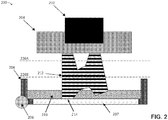
- FIG. 2 depicts a cross-section of an additive fabrication such as system 100 during fabrication of a part 212.
- a downward facing build platform 204 directly opposes the floor of the resin container 206 filled with a photopolymer resin 210.
- the part being fabricated 212 is formed layerwise with the initial layer attached to the build platform 204.
- a region 207 of the resin container's floor is transparent to actinic radiation, which allows portions of the thin layer of liquid photocurable resin resting on the floor 214 to be targeted by the radiation through the transparent portion. Exposure to actinic radiation cures a thin layer of liquid resin which causes it to harden between the two surfaces to which it is adjacent (the base of container 206 and a previously formed layer of part 212).
- the top side of the cured resin layer typically bonds to the bottom surface of the build platform 204 or with the previously cured resin layer, as well as to the transparent floor of the container 214.
- the bond of the cured resin with the transparent floor of the container is undesirable, and is typically broken so that additional layers may be formed.
- a separating force is applied when the bottom of the resin container 206 is mechanically separated, or "peeled," from the part 212 by pivoting the container 206 about a fixed axis 208 on one side of the container.
- This peeling step involves moving the resin container 206 away from the part 212 followed by a move of the resin container 206 back towards the part 212. Following this motion, a new layer of liquid resin is available for exposure and addition to the part being formed. Each step of the aforementioned curing and peeling processes may continue until the part is fully created.
- Some resin containers may be made of a single actinically transparent material. This material may have been chosen to allow for actinic radiation to pass through the lower portion of the resin container (e.g. without substantial attenuation) to initiate curing of liquid resin. Such designs, however, may also allow unwanted actinic radiation from the environment or other sources to penetrate the resin container and potentially expose the resin to the radiation. Accordingly, when using such containers the resin is typically transferred to an actinically opaque container during storage of the resin. As discussed above, however, this may lead to additional problems such as curing of resin that adheres to the surfaces, etc.
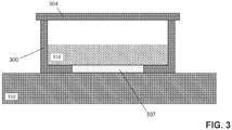
- the illustrative storage unit depicted in FIG. 3 addresses these issues by providing a single storage unit that may be used during additive fabrication and during storage.
- storage unit 300 sits on a surface 350, which may be a table, shelf, or other suitable surface commonly used for storage, and which is actinically opaque.
- the storage unit includes a removable lid 304 and a region that is actinically transparent 307. The remainder of the storage unit (other than region 307) is actinically opaque.
- the storage unit comprises a liquid resin 310.
- the resin 310 is surrounded by actinically opaque material. While there is an actinically transparent region 307 of the storage unit, actinic radiation originating outside of the storage unit is substantially blocked from reaching the resin due to the storage unit being placed on the surface 350, which is actinically opaque.
- Multiple of storage units 300 may be placed on top of one another such that the collection of storage units is actinically opaque (since the actinically transparent region of each storage unit will be adjacent to the actinically opaque lid of the storage unit on which it is rests).
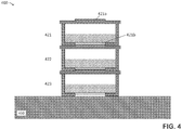
- FIG. 4 depicts stacked storage units each storing photopolymer resin, according to some embodiments.
- the storage units 421, 422 and 423 shown in the example of FIG. 4 each include a raised portion in their lid (of which lid 421a is one example) and a recessed portion in their bottom face that is actinically transparent (of which portion 421b is one example). The recessed portions mate with the raised portions such that the lids stack together.
- the collection of storage units 421, 422 and 423 is collectively actinically opaque since each actinically transparent region is adjacent to an actinically opaque lid (in the case of the regions of storage units 421 and 422) or is adjacent to surface 450 (in the case of the region of storage unit 423).
- one advantage of the present invention is that embodiments may not only be effectively used as resin containers within a stereo lithographic device during the operation and formation of a part but also be effectively used as a storage unit for photopolymer resin when it is kept outside of the stereo lithographic device.
- actinically opaque portions of the storage unit may serve to shield the contents of the resin container from unwanted environmental actinic radiation that might otherwise enter through the sides or other regions of the container.
- the bottom of the container remains actinically transparent, the inventors have observed that resin containers are typically stored on a flat surface, such as the top of a table or desk. As will be appreciated, such surfaces are, typically, themselves opaque to relevant frequencies of actinic radiation.
- a resin container according to embodiments of the preferred invention can therefore be substantially isolated from environmental actinic radiation by covering the top opening of the resin container, such as with a lid made of an actinically opaque material.
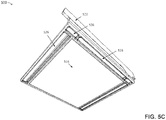
- FIGs. 5A-5C depict an illustrative container for storing photopolymer resin, according to some embodiments.
- an actinically transparent window 516 of container 500 allows for transmission of actinic radiation.
- the window is located within an actinically opaque container frame 520 that blocks a substantial amount of actinic radiation from passing through the frame 520.
- photopolymer resin within the resin container may be intentionally exposed to actinic radiation at the bottom layer of the resin container.
- container 500 may be used as container 106 shown in FIG. 1 and/or may be used as container 206 shown in FIG. 2 wherein actinic radiation is directed through the window 516 to resin located within the container.
- a recessed area 526 is integrated into the resin container frame 518 thereby forming a spout that may allow for easy removal of resin from the resin container.
- the spout 526 may provide reduced spillage compared with comparable pouring from container 500 than would occur without such a spout.
- recessed points 524 and stopping features 522 may be formed within the resin container in order to assist with the alignment of container 500 within a stereolithographic device.
- the actinically transparent window 516 may be located at a height above the lowest point of the resin container frame 520 so as to avoid damage, such as scratches or contamination, to the window potentially caused by placing the resin container on a flat surface, such as a table or shelf.
- the inventors have found that even minor offsets (for example, offsets between 0.1 mm and 1.0 mm) of the actinically transparent window above the lowest level of the resin container may substantially reduce the risk of such damage or contamination.
- Such minor offsets of the actinically transparent window may also help to ensure that actinic radiation is blocked from entering through the actinically transparent window when the resin container frame 520 is placed on an actinically opaque surface for storage.
- differential coloration of the actinically opaque resin frame and the actinically transparent window may advantageously demarcate the window region so as to assist users in keeping said window region protected from debris or contamination, such as fingerprints.
- Such differential coloration can be advantageously provided by the same techniques and treatments used to render the resin container frame actinically opaque.
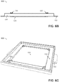
- FIGs. 6A-6C depict an illustrative storage unit lid, according to some embodiments.
- Lid 600 may be removably attached to any suitable storage container, such as container 500 shown in FIGs. 5A-5C .
- a top recess 628 on lid 600 may provide clearance between the lid and an actinically transparent window in the resin container immediately above it (not shown).
- a raised portion 634 of the lid may provide a secure surface on which the resin container immediately above the lid may rest.
- the top recess 628 may further advantageously provide a recess wherein a build platform may be placed when not in use. In the example of FIGs.
- tabs 632 may be folded down over the sides of a container (e.g., container 500) to improve the fit between lid and resin container. For instance, the tabs may snap or otherwise lock into position to provide an actinically opaque seal between the lid 600 and a container such as container 500.
- a container e.g., container 500
- a storage container comprising an actinically transparent window and an actinically opaque frame may be formed by assembling two or more components made from materials with desired optical properties.
- materials such as poly-methyl methacrylate (commonly known commercially as "Plexiglas” or “ACRYLITE"), or other acrylics, may be used.
- poly-methyl methacrylate material may be produced to be substantially transparent to actinic radiation, while other formulations yield poly-methyl methacrylate material substantially opaque to actinic radiation, such as is commercially available as ACRYPET VH-067A from Mitsubishi Rayon Polymer Nantong Co., Ltd.
- a storage container may be composed of a single material transparent to actinic radiation with regions of the container coated so as to render the container frame actinically opaque. It may be advantageous that the actinically opaque frame of the resin container remain at least partially transparent to certain portions of the visible spectrum so as to allow the user to observe the status of the photopolymer resin, including the amount of remaining photopolymer resin, as well as the status of part formation within the resin container during operation.
- FIG. 7 depicts a method of storing photopolymer resin used in additive fabrication, according to some embodiments.
- Method 700 begins in act 701 in which a part is produced via additive fabrication.
- Act 701 may comprise use of any suitable additive fabrication device to produce the part, and may use any one or more additive fabrication techniques.
- the part is produced in act 701 via stereolithography.
- the additive fabrication device in method 700 includes, as a component, a container in which material used in the additive fabrication process of act 701 is stored.
- the container is remove from the additive fabrication device used in act 701, and in act 703 a lid is attached (e.g., removably attached) to the container.
- the container may include actinically transparent regions in addition to actinically opaque regions.
- the container of method 700 may include container 300 shown in FIG. 3 , container 421, 422 and/or 423 shown in FIG. 4 and/or container 500 shown in FIGs. 5A-5C .
- the lid may be actinically opaque.
- the lid of method 700 may include lid 304 shown in FIG. 3 , lid 421a shown in FIG. 4 , and/or lid 600 shown in FIGs. 6A-6C .
Landscapes
- Engineering & Computer Science (AREA)
- Chemical & Material Sciences (AREA)
- Materials Engineering (AREA)
- Physics & Mathematics (AREA)
- Mechanical Engineering (AREA)
- Optics & Photonics (AREA)
- Manufacturing & Machinery (AREA)
- Health & Medical Sciences (AREA)
- Toxicology (AREA)
- Oral & Maxillofacial Surgery (AREA)
- Thermal Sciences (AREA)
- Packages (AREA)
Description
- The present invention relates generally to systems and methods for storing photopolymers used in additive fabrication, e.g., 3-dimensional printing.
- Additive fabrication, e.g., 3-dimensional (3D) printing, provides techniques for fabricating objects, typically by causing portions of a building material to solidify at specific locations. Additive fabrication techniques may include stereo lithography, selective or fused deposition modeling, direct composite manufacturing, laminated object manufacturing, selective phase area deposition, multi-phase jet solidification, ballistic particle manufacturing, particle deposition, laser sintering or combinations thereof. Many additive fabrication techniques build parts by forming successive layers, which are typically cross-sections of the desired object. Typically each layer is formed such that it adheres to either a previously formed layer or a substrate upon which the object is built.
- In one approach to additive fabrication, known as stereo lithography, solid objects are created by successively forming thin layers of a curable polymer resin, typically first onto a substrate and then one on top of another. Exposure to actinic radiation cures a thin layer of liquid resin, which causes it to harden and adhere to previously cured layers or the bottom surface of the build platform.
- Document
WO_2014/016668 A1 discloses a cartridge container for a photocurable polymer having a bottom portion transparent to the curing radiation, and side walls opaque to this radiation. The container also comprises a top opening closable by an opaque lid. - Systems and methods for storing photopolymers used in additive fabrication are provided. A storage unit according to the invention is defined in claim 1, whereas a method of additive fabrication according to the invention is defined in claim 13. Preferred embodiments are defined in the respective dependent claims.
- According to some aspects, a storage unit is provided comprising a photopolymer resin. The storage unit has a bottom face comprising at least one region of actinically transparent material that is actinically transparent with respect to the photopolymer resin. The storage unit also has at least one wall that extends upwards from the bottom face and that comprises at least one region of actinically opaque material that is actinically opaque with respect to the photopolymer resin. Furthermore, the storage unit has a lid comprising the actinically opaque material and removably connectable to the at least one wall.
- According to some aspects, a method of additive fabrication is provided. The method includes producing at least one part from a photopolymer resin via one or more additive fabrication techniques, wherein the photopolymer resin is contained within a container that is a component of an additive fabrication device. The method further includes removing the container from the additive fabrication device and attaching a lid to the container. The lid and container comprise an actinically opaque material and comprise at least one region of actinically transparent material on a bottom face of the container.
- The foregoing is a non-limiting summary of the invention, which is defined by the attached claims.
- The accompanying drawings are not intended to be drawn to scale. For purposes of clarity, not every component may be labeled in every drawing. In the drawings:
-
FIG. 1 depicts an illustrative stereolithography system, according to some embodiments; -
FIG. 2 depicts a cross-section of an illustrative stereolithography system during fabrication of a part, according to some embodiments; -
FIG. 3 depicts a cross-section of an illustrative storage unit storing a photopolymer resin, according to some embodiments; -
FIG. 4 depicts stacked storage units each storing photopolymer resin, according to some embodiments; -
FIGs. 5A-5C depict an illustrative container for storing photopolymer resin, according to some embodiments; -
FIGs. 6A-6C depict an illustrative storage unit lid, according to some embodiments; and -
FIG. 7 depicts a method of storing photopolymer resin used in additive fabrication, according to some embodiments. - The present invention relates generally to systems and methods for storing photopolymers used in additive fabrication, e.g., 3-dimensional printing. In particular, the present invention is directed to methods and apparatuses which provide storage of photopolymers suitable for use in additive fabrication during periods in which the photopolymers are not actively being used for additive fabrication. In some embodiments, the methods and apparatuses described herein may provide techniques for storing and transporting materials sensitive to actinic radiation in a format that can be easily loaded, unloaded, and used in material processing. As a result, sensitive materials may be more reliably used in a stereolithography process with reduced user error and increased convenience.
- As discussed above, in stereolithography solid objects may be created by successively curing layers of liquid resin via exposure of the resin to actinic radiation. However, actinic radiation capable of causing a liquid resin to partially or completely cure may be present in natural light and/or in other ambient radiation. While during additive fabrication the resin may be shielded from unwanted sources of actinic radiation, unintentional exposure of a resin to actinic radiation may occur while the resin is not being used for additive fabrication. For instance, resin material may be stored in a vessel that is opaque to actinic radiation, yet unintentional exposure to actinic radiation may occur during loading and/or unloading of the resin material to and/or from the vessel. Such unintentional exposure may cause premature curing and/or other undesirable changes to properties of the resin. In addition, during transfer of the resin from one vessel to another some resin may adhere to the vessel and/or the device's container. This resin may be partially or complete cured by ambient radiation, leading to a coating of a solid polymer on the vessel, which may inhibit subsequent use of the vessel.
- The inventors have recognized and appreciated that there are benefits to using a single storage unit for both storage of a resin material and for containing the resin material during additive fabrication. With such a configuration, it may be unnecessary to transfer resin material from the storage unit, leading to reduction of unintentional exposure and leading to easier use of the resin since the resin need not be poured from the storage unit into another vessel for fabrication.
- In order that a single storage unit be used both for storage and during additive fabrication, it is desirable that the unit may be configured to be actinically opaque during storage yet include at least one actinically transparent region through which actinic radiation may be directed (e.g., to resin within the container) during additive fabrication. The inventors have recognized and appreciated that a storage unit may be configured in such a way by arranging an actinically transparent region of the unit such that during storage (which may include placing of a storage unit onto a surface and/or stacking of storage units) the actinically transparent region of the unit is substantially shielded from actinic radiation due to natural placement of the unit for storage.
- According to some embodiments, the storage unit includes a region that is transparent to actinic radiation such that the storage unit may be used in stereolithographic processes in which actinic radiation is supplied to the resin within the storage unit through that surface. The remainder of the storage unit is opaque to actinic radiation, and includes a removable lid that may be removed when the storage unit is installed within an additive fabrication device. Accordingly, the storage unit may be stored with the lid attached and also used without the lid directly as a component of an additive fabrication device. As such, it may become unnecessary to remove the resin from the storage container.
- According to some embodiments, the storage unit is shaped such that the actinically transparent region is covered by a table or other surface during storage of the resin (i.e., at times when additive fabrication is not being performed). As such, the resin inside the storage unit may be substantially shielded from sources of actinic radiation exterior to the storage unit. When the storage unit is used as a component of an additive fabrication device, the shielding surface is not present, and the actinically transparent region may be used to direct actinic radiation to resin located within the unit. Accordingly, a single storage unit may inhibit exposure of a resin to actinic radiation during storage using a combination of actinically opaque material and surfaces adjacent to the unit during storage, yet may allow actinic radiation to pass through the actinically transparent portion of the storage unit during additive fabrication.
- The storage unit includes a removable lid. The lid is opaque to actinic radiation and may be configured to be attached to a remainder of the storage unit when the storage unit is used for storage of resin, and is configured to be removed from the storage unit when the storage unit is installed within an additive fabrication device. The lid may be shaped so as to allow multiple storage units to be stacked on top of one another. For instance, the lid may include one or more portions shaped to mate with respective portions of a bottom side of a storage unit. The lid may also include one or more locking mechanisms configured to provide a seal or other tight fit between the lid and the remainder of the storage unit. In some cases, such a locking mechanism may include a portion on the lid and a portion on the remainder of the storage unit such that the two portions may mate and/or lock together to hold the lid in place.
- According to the invention one or more portions of a bottom side of a storage unit that are actinically transparent is shaped to mate with respective portions of a lid of the storage unit. In such a configuration, mating the two storage units via the respective portions may cause the portions of the lid to block actinic radiation that would otherwise pass through the actinically transparent portions of the bottom side of the storage unit. In this way, the storage units may be designed to stack in order to make the stack of storage units collectively actinically opaque, or to at least reduce the number of regions of the collection of storage units that are exposed to actinic radiation. For instance, storage units that are stackable as described above and that include an actinically transparent region on a bottom surface may be stacked such that the only actinically transparent region not covered by another storage unit is on the underside of the bottom storage unit of the stack.
- In general, incidence of actinic radiation upon a photopolymer material can have various effects. For instance , actinic radiation may cure the material, at least in part (e.g., it may harden the material to some extent). Alternatively, the actinic radiation may have no measurable effect on the material. Which effect(s) occur when a photopolymer is exposed to actinic radiation may depend, at least in part, on the wavelength(s) of radiation exhibited by the actinic radiation and/or the amplitude of the radiation at one or more of the wavelengths. For instance, since a given photopolymer may react to a particular wavelength, or wavelengths, of radiation, the effect of actinic radiation incident upon the photopolymer may depend upon which of the wavelengths, if any, are present in the actinic radiation.
- In some embodiments, an actinically opaque material substantially attenuates (e.g., reduces the amplitude by 50-100%) the amplitude of at least one wavelength of radiation passing through the material (e.g., 405 nm wavelength light), wherein the at least one wavelength is associated with curing of at least one photopolymer. It may be the case that the same actinically opaque material does not substantially attenuate (though may attenuate to some degree) other wavelengths that could be used to cure a different photopolymer. Thus, in some embodiments, a material may be considered actinically opaque if the material is configured to substantially attenuate the transmission of at least one wavelength that is capable of curing a particular photopolymer, or particular photopolymers (though may not substantially attenuate other wavelengths that are capable of curing a different photopolymer). In some embodiments, an actinically transparent material does not substantially attenuate (e.g., reduces the amplitude by less than 50%) the amplitude of at least one wavelength of radiation passing through the material (e.g., 405 nm wavelength light), wherein the at least one wavelength is associated with curing of at least one photopolymer.
- In some embodiments, an actinically opaque material substantially attenuates (e.g., reduces the amplitude by 50-100%) the amplitude of at least one wavelength of radiation passing through the material, wherein the at least one wavelength is associated with curing a class of photopolymers. Photopolymers that share particular chemical characteristics often have similar responses to similar radiation (e.g., similar amplitude and/or wavelengths) and, in some embodiments, a material may be considered actinically opaque if the material is configured to substantially attenuate the transmission of at least one wavelength that is capable of curing any of a class of photopolymers. The same wavelengths may, or may not, be capable of curing photopolymers that are not members of the class. In some embodiments, an actinically transparent material does not substantially attenuate (e.g., reduces the amplitude by less than 50%) the amplitude of at least one wavelength of radiation passing through the material, wherein the at least one wavelength is associated with curing of a class of photopolymers.
- In some embodiments, substantial attenuation of radiation by a material comprises reducing the amplitude of the radiation by between 70% and 100%. In some embodiments, substantial attenuation of radiation by a material comprises reducing the amplitude of the radiation by between 90% and 100%. In some embodiments, substantial attenuation of radiation by a material comprises reducing the amplitude of the radiation by between 95% and 100%.
- In some embodiments, a material does not substantially attenuate radiation if the material reduces the amplitude of the radiation by between 0% and 50%. In some embodiments, a material does not substantially attenuate radiation if the material reduces the amplitude of the radiation by between 0% and 30%. In some embodiments, a material does not substantially attenuate radiation if the material reduces the amplitude of the radiation by between 0% and 10%.
- One illustrative additive manufacturing technology considered herein is stereolithography, such as used by the Form 1 3D Printer sold by Formlabs, Inc., the assignee of the present application. The Form 1 system is described more fully in one or more of
U.S. Patent Application Serial No. 14/245,765, filed April 4, 2014 U.S. Patent Application Ser. No. 13/848,979, filed March 22, 2013 U.S. Patent Application Ser. No. 61/808,714, filed April 5, 2013 -
FIG. 1 depicts an illustrative stereolithography system, according to some embodiments.System 100 includes abase housing 105 containing various mechanical, optical, electrical, and electronic components that operate the system. Anupper housing 103 is substantially opaque to actinic radiation frequencies used within the system for hardening of liquid resin. Theupper housing 103 protects thebuild platform 104 and an insertedresin container 106, from unwanted exposure from actinic radiation. The upper housing may, or may not, be transparent to other radiation frequencies. - During additive fabrication, the
resin container 106 may be filled with a photopolymer resin.FIG. 2 depicts a cross-section of an additive fabrication such assystem 100 during fabrication of apart 212. In the example ofFIG. 2 , a downward facingbuild platform 204 directly opposes the floor of theresin container 206 filled with a photopolymer resin 210. The part being fabricated 212 is formed layerwise with the initial layer attached to thebuild platform 204. - A
region 207 of the resin container's floor is transparent to actinic radiation, which allows portions of the thin layer of liquid photocurable resin resting on thefloor 214 to be targeted by the radiation through the transparent portion. Exposure to actinic radiation cures a thin layer of liquid resin which causes it to harden between the two surfaces to which it is adjacent (the base ofcontainer 206 and a previously formed layer of part 212). - The top side of the cured resin layer typically bonds to the bottom surface of the
build platform 204 or with the previously cured resin layer, as well as to the transparent floor of thecontainer 214. The bond of the cured resin with the transparent floor of the container is undesirable, and is typically broken so that additional layers may be formed. In an illustrative implementation, such as the Form 1 3D printer distributed by Formlabs Inc., depicted inFIG. 1 , a separating force is applied when the bottom of theresin container 206 is mechanically separated, or "peeled," from thepart 212 by pivoting thecontainer 206 about a fixedaxis 208 on one side of the container. This peeling step involves moving theresin container 206 away from thepart 212 followed by a move of theresin container 206 back towards thepart 212. Following this motion, a new layer of liquid resin is available for exposure and addition to the part being formed. Each step of the aforementioned curing and peeling processes may continue until the part is fully created. - Some resin containers, unlike
resin container 106 depicted inFIG. 1 andresin container 206 depicted inFIG. 2 , may be made of a single actinically transparent material. This material may have been chosen to allow for actinic radiation to pass through the lower portion of the resin container (e.g. without substantial attenuation) to initiate curing of liquid resin. Such designs, however, may also allow unwanted actinic radiation from the environment or other sources to penetrate the resin container and potentially expose the resin to the radiation. Accordingly, when using such containers the resin is typically transferred to an actinically opaque container during storage of the resin. As discussed above, however, this may lead to additional problems such as curing of resin that adheres to the surfaces, etc. - The illustrative storage unit depicted in
FIG. 3 addresses these issues by providing a single storage unit that may be used during additive fabrication and during storage. In the example ofFIG. 3 ,storage unit 300 sits on asurface 350, which may be a table, shelf, or other suitable surface commonly used for storage, and which is actinically opaque. The storage unit includes aremovable lid 304 and a region that is actinically transparent 307. The remainder of the storage unit (other than region 307) is actinically opaque. The storage unit comprises aliquid resin 310. - In the example of
FIG. 3 , by placing thestorage unit 300 onsurface 350, theresin 310 is surrounded by actinically opaque material. While there is an actinicallytransparent region 307 of the storage unit, actinic radiation originating outside of the storage unit is substantially blocked from reaching the resin due to the storage unit being placed on thesurface 350, which is actinically opaque. Multiple ofstorage units 300 may be placed on top of one another such that the collection of storage units is actinically opaque (since the actinically transparent region of each storage unit will be adjacent to the actinically opaque lid of the storage unit on which it is rests). -
FIG. 4 depicts stacked storage units each storing photopolymer resin, according to some embodiments. Thestorage units FIG. 4 each include a raised portion in their lid (of whichlid 421a is one example) and a recessed portion in their bottom face that is actinically transparent (of whichportion 421b is one example). The recessed portions mate with the raised portions such that the lids stack together. The collection ofstorage units storage units 421 and 422) or is adjacent to surface 450 (in the case of the region of storage unit 423). - Accordingly, one advantage of the present invention is that embodiments may not only be effectively used as resin containers within a stereo lithographic device during the operation and formation of a part but also be effectively used as a storage unit for photopolymer resin when it is kept outside of the stereo lithographic device. As described above, actinically opaque portions of the storage unit may serve to shield the contents of the resin container from unwanted environmental actinic radiation that might otherwise enter through the sides or other regions of the container. While the bottom of the container remains actinically transparent, the inventors have observed that resin containers are typically stored on a flat surface, such as the top of a table or desk. As will be appreciated, such surfaces are, typically, themselves opaque to relevant frequencies of actinic radiation. As a result, no actinic radiation (or a negligible quantity of actinic radiation) may enter the resin container through the actinically transparent
window. When used as a storage container, a resin container according to embodiments of the preferred invention can therefore be substantially isolated from environmental actinic radiation by covering the top opening of the resin container, such as with a lid made of an actinically opaque material. -
FIGs. 5A-5C depict an illustrative container for storing photopolymer resin, according to some embodiments. In the example ofFIGs. 5A-5C , an actinicallytransparent window 516 ofcontainer 500 allows for transmission of actinic radiation. The window is located within an actinicallyopaque container frame 520 that blocks a substantial amount of actinic radiation from passing through theframe 520. By virtue of the actinicallytransparent window 516, photopolymer resin within the resin container may be intentionally exposed to actinic radiation at the bottom layer of the resin container. For instance,container 500 may be used ascontainer 106 shown inFIG. 1 and/or may be used ascontainer 206 shown inFIG. 2 wherein actinic radiation is directed through thewindow 516 to resin located within the container. - In the example of
FIGs. 5A-5C , a recessedarea 526 is integrated into theresin container frame 518 thereby forming a spout that may allow for easy removal of resin from the resin container. For instance, thespout 526 may provide reduced spillage compared with comparable pouring fromcontainer 500 than would occur without such a spout. In addition, recessedpoints 524 and stoppingfeatures 522 may be formed within the resin container in order to assist with the alignment ofcontainer 500 within a stereolithographic device. - The actinically
transparent window 516 may be located at a height above the lowest point of theresin container frame 520 so as to avoid damage, such as scratches or contamination, to the window potentially caused by placing the resin container on a flat surface, such as a table or shelf. The inventors have found that even minor offsets (for example, offsets between 0.1 mm and 1.0 mm) of the actinically transparent window above the lowest level of the resin container may substantially reduce the risk of such damage or contamination. Such minor offsets of the actinically transparent window may also help to ensure that actinic radiation is blocked from entering through the actinically transparent window when theresin container frame 520 is placed on an actinically opaque surface for storage. In addition, differential coloration of the actinically opaque resin frame and the actinically transparent window may advantageously demarcate the window region so as to assist users in keeping said window region protected from debris or contamination, such as fingerprints. Such differential coloration can be advantageously provided by the same techniques and treatments used to render the resin container frame actinically opaque. -
FIGs. 6A-6C depict an illustrative storage unit lid, according to some embodiments.Lid 600 may be removably attached to any suitable storage container, such ascontainer 500 shown inFIGs. 5A-5C . As with the example ofFIG. 4 , atop recess 628 onlid 600 may provide clearance between the lid and an actinically transparent window in the resin container immediately above it (not shown). A raisedportion 634 of the lid may provide a secure surface on which the resin container immediately above the lid may rest. Thetop recess 628 may further advantageously provide a recess wherein a build platform may be placed when not in use. In the example ofFIGs. 6A-6C ,tabs 632 may be folded down over the sides of a container (e.g., container 500) to improve the fit between lid and resin container. For instance, the tabs may snap or otherwise lock into position to provide an actinically opaque seal between thelid 600 and a container such ascontainer 500. - Storage containers and/or storage units as described above may be formed in any suitable way. According to some embodiments, a storage container comprising an actinically transparent window and an actinically opaque frame may be formed by assembling two or more components made from materials with desired optical properties. In some implementations, materials such as poly-methyl methacrylate (commonly known commercially as "Plexiglas" or "ACRYLITE"), or other acrylics, may be used. In some formulations, poly-methyl methacrylate material may be produced to be substantially transparent to actinic radiation, while other formulations yield poly-methyl methacrylate material substantially opaque to actinic radiation, such as is commercially available as ACRYPET VH-067A from Mitsubishi Rayon Polymer Nantong Co., Ltd.
- According to some embodiments, a storage container may be composed of a single material transparent to actinic radiation with regions of the container coated so as to render the container frame actinically opaque. It may be advantageous that the actinically opaque frame of the resin container remain at least partially transparent to certain portions of the visible spectrum so as to allow the user to observe the status of the photopolymer resin, including the amount of remaining photopolymer resin, as well as the status of part formation within the resin container during operation.
-
FIG. 7 depicts a method of storing photopolymer resin used in additive fabrication, according to some embodiments.Method 700 begins inact 701 in which a part is produced via additive fabrication. Act 701 may comprise use of any suitable additive fabrication device to produce the part, and may use any one or more additive fabrication techniques. According to some embodiments, the part is produced inact 701 via stereolithography. - Irrespective of which additive fabrication technique(s) are used, the additive fabrication device in
method 700 includes, as a component, a container in which material used in the additive fabrication process ofact 701 is stored. Inact 702, the container is remove from the additive fabrication device used inact 701, and in act 703 a lid is attached (e.g., removably attached) to the container. Inmethod 700, the container may include actinically transparent regions in addition to actinically opaque regions. For instance, the container ofmethod 700 may includecontainer 300 shown inFIG. 3 ,container FIG. 4 and/orcontainer 500 shown inFIGs. 5A-5C . The lid may be actinically opaque. For instance, the lid ofmethod 700 may includelid 304 shown inFIG. 3 ,lid 421a shown inFIG. 4 , and/orlid 600 shown inFIGs. 6A-6C .
Claims (14)
- A storage unit (300, 421, 500) for additive fabrication, comprising:a photopolymer resin (310);a bottom face comprising at least one region of actinically transparent material (307, 421b, 516), the actinically transparent material being actinically transparent with respect to the photopolymer resin;at least one wall extending upwards from said bottom face comprising at least one region of actinically opaque material, the actinically opaque material being actinically opaque with respect to the photopolymer resin; anda lid (304, 600) comprising the actinically opaque material and removably connectable to the at least one wall,characterized in that the region of actinically transparent material is a recessed portion (421b), and the lid includes a raised portion (421a) configured to mate with the recessed portion in the bottom face of a second storage unit (422, 500).
- The storage unit (300, 421, 500) of claim 1, wherein the bottom face, the at least one wall and the lid (304, 600) form an enclosure that is actinically opaque but for the at least one region of actinically transparent material (307, 421b, 516).
- The storage unit (300, 421, 500) of claim 1, wherein the actinically opaque material substantially attenuates an amplitude of at least one wavelength of radiation passing through the material.
- The storage unit (300, 421, 500) of claim 3, wherein the at least one wavelength is associated with curing of at least one photopolymer.
- The storage unit (300, 421, 500) of claim 3, wherein the at least one wavelength is associated with curing of a class of photopolymers.
- The storage unit (300, 421, 500) of claim 1, comprising four walls extending upwards from the bottom face, each wall comprising the actinically opaque material.
- The storage unit (300, 421, 500) of claim 1, wherein the at least one wall includes a spout (526).
- The storage unit (300, 421, 500) of claim 1, wherein the bottom face is formed from the actinically opaque material but for the at least one region of actinically transparent material (307, 421b, 516).
- The storage unit (300, 421, 500) of claim 1, wherein the storage unit is configured to be installable into a stereolithographic additive fabrication device.
- The storage unit (300, 421, 500) of claim 1, wherein the at least one region of actinically transparent material (307, 421b, 516) is vertically offset from a lowest level of the bottom face.
- The storage unit (300, 421, 500) of claim 1, wherein the lid (304, 600) comprises a plurality of tabs (632) adapted to be actuated to create a locking engagement between the lid and the at least one wall.
- The storage unit (300, 421, 500) of claim 1, wherein the bottom face is configured to mate with a third storage unit comprising one or more second walls, wherein the bottom face is configured to mate with the one or more second walls.
- A method of additive fabrication, comprising:producing at least one part from a photopolymer resin via additive fabrication, the photopolymer resin located in a container that is a component of an additive fabrication device;removing the container from the additive fabrication device; andattaching a lid to the container,wherein the lid and the container comprise an actinically opaque material and comprise at least one region of actinically transparent material on a bottom face of the container, andcharacterized in that the region of actinically transparent material is a recessed portion, and the lid includes a raised portion configured to mate with the recessed portion in the bottom face of a second container.
- The method of claim 13, wherein the additive fabrication device comprises at least one source of actinic radiation, and wherein the at least one region of actinically transparent material is configured to be positioned such that the actinic radiation may be transmitted to the photopolymer resin through the at least one region when the container is installed as the component of the additive fabrication device.
Applications Claiming Priority (2)
| Application Number | Priority Date | Filing Date | Title |
|---|---|---|---|
| US201462010228P | 2014-06-10 | 2014-06-10 | |
| PCT/US2015/035069 WO2015191689A1 (en) | 2014-06-10 | 2015-06-10 | Improved resin container for stereolithography |
Publications (2)
| Publication Number | Publication Date |
|---|---|
| EP3154761A1 EP3154761A1 (en) | 2017-04-19 |
| EP3154761B1 true EP3154761B1 (en) | 2018-10-31 |
Family
ID=53484171
Family Applications (1)
| Application Number | Title | Priority Date | Filing Date |
|---|---|---|---|
| EP15731194.5A Active EP3154761B1 (en) | 2014-06-10 | 2015-06-10 | Improved resin container for stereolithography |
Country Status (5)
| Country | Link |
|---|---|
| US (2) | US9878470B2 (en) |
| EP (1) | EP3154761B1 (en) |
| JP (1) | JP6637037B2 (en) |
| CN (1) | CN106573397B (en) |
| WO (1) | WO2015191689A1 (en) |
Families Citing this family (36)
| Publication number | Priority date | Publication date | Assignee | Title |
|---|---|---|---|---|
| EP3916783A3 (en) * | 2014-12-09 | 2022-07-13 | Google LLC | Method of making a three dimensional horizontal coil structure within a mold compound package having at least one integrated circuit chip |
| USD768214S1 (en) * | 2015-01-30 | 2016-10-04 | Sti Co., Ltd. | 3D printer |
| USD783693S1 (en) * | 2015-08-11 | 2017-04-11 | Formlabs, Inc. | Three-dimensional printer |
| ITUB20154169A1 (en) | 2015-10-02 | 2017-04-02 | Thelyn S R L | Self-lubricating substrate photo-hardening method and apparatus for the formation of three-dimensional objects. |
| WO2017116990A1 (en) * | 2015-12-31 | 2017-07-06 | Formlabs, Inc. | Systems and methods of flexible substrates for additive fabrication |
| USD777809S1 (en) * | 2016-01-05 | 2017-01-31 | Xyzprinting, Inc. | 3D printer |
| USD777228S1 (en) * | 2016-01-05 | 2017-01-24 | Xyzprinting, Inc. | 3D printer |
| USD777227S1 (en) * | 2016-01-05 | 2017-01-24 | Xyzprinting, Inc. | Stereolithography machine |
| USD777808S1 (en) * | 2016-01-05 | 2017-01-31 | Xyzprinting, Inc. | 3D printer |
| USD791203S1 (en) * | 2016-03-15 | 2017-07-04 | Shenzhen Longer 3D Technology Co., Ltd. | 3D printer |
| EP3538367A4 (en) | 2016-11-08 | 2020-07-01 | Formlabs, Inc. | Multi-material separation layers for additive fabrication |
| USD845357S1 (en) * | 2017-05-19 | 2019-04-09 | Hangzhou Weibin Technology Co., Ltd. | 3D printer |
| CN107160683B (en) * | 2017-06-27 | 2023-05-12 | 苏州慧通汇创科技有限公司 | Multi-laser light source forming 3D printer |
| CN107214959B (en) * | 2017-06-27 | 2023-04-28 | 苏州慧通汇创科技有限公司 | Laser forming 3D printer capable of printing in batches |
| USD861748S1 (en) * | 2017-09-01 | 2019-10-01 | Hangzhou Weibin Technology Co., Ltd. | 3D printer |
| US20190358902A1 (en) | 2018-05-07 | 2019-11-28 | Formlabs, Inc. | Multi-material separation layers for additive fabrication |
| US11318673B2 (en) | 2018-06-01 | 2022-05-03 | Formlabs, Inc. | Film tensioning techniques for additive fabrication and related systems and methods |
| US11203156B2 (en) | 2018-08-20 | 2021-12-21 | NEXA3D Inc. | Methods and systems for photo-curing photo-sensitive material for printing and other applications |
| EP3613559A1 (en) * | 2018-08-22 | 2020-02-26 | Coltène/Whaledent AG | Single-use cartridge and method for additive manufacturing from photopolymer resin |
| JP7407459B2 (en) | 2018-11-09 | 2024-01-04 | ネクサ3ディー インコーポレイテッド | 3D printing system |
| US11911956B2 (en) | 2018-11-21 | 2024-02-27 | Adaptive 3D Technologies | Using occluding fluids to augment additive manufacturing processes |
| KR20210125473A (en) * | 2018-11-21 | 2021-10-18 | 어댑티브 3디 테크놀로지스 엘엘씨 | Use of Occlusion Fluids to Improve Additive Manufacturing Processes |
| WO2020123168A1 (en) | 2018-12-14 | 2020-06-18 | 3D Systems, Inc. | Precision optical assembly for three dimensional printing |
| US11207833B2 (en) | 2018-12-14 | 2021-12-28 | 3D Systems, Inc. | Precision optical assembly method for three dimensional printing |
| USD906381S1 (en) * | 2019-03-15 | 2020-12-29 | Formlabs, Inc. | Three-dimensional printer |
| USD893564S1 (en) * | 2019-03-15 | 2020-08-18 | Formlabs, Inc. | Three-dimensional printer |
| USD905135S1 (en) * | 2019-03-15 | 2020-12-15 | Formlabs, Inc. | Three-dimensional printer |
| US11167473B2 (en) | 2019-03-18 | 2021-11-09 | NEXA3D Inc. | System for additive manufacture |
| US10967573B2 (en) | 2019-04-02 | 2021-04-06 | NEXA3D Inc. | Tank assembly and components thereof for a 3D printing system |
| FI130087B (en) * | 2019-11-15 | 2023-01-31 | Planmeca Oy | Stereolithography apparatus and receptacle |
| US11413819B2 (en) | 2020-09-03 | 2022-08-16 | NEXA3D Inc. | Multi-material membrane for vat polymerization printer |
| WO2022148547A1 (en) | 2021-01-11 | 2022-07-14 | Readily3D Sa | System and method for a sterile, precise and fast handling of resin containers in volumetric printers |
| US20250135719A1 (en) * | 2022-01-31 | 2025-05-01 | University Of Cincinnati | Lift-Based Peel Separation for Inverted Vat Photopolymerization 3D Printing |
| US12023865B2 (en) | 2022-08-11 | 2024-07-02 | NEXA3D Inc. | Light engines for vat polymerization 3D printers |
| USD1025150S1 (en) * | 2022-08-15 | 2024-04-30 | Shenzhen Elegoo Technology Co., Ltd | 3D printer |
| USD1114855S1 (en) * | 2023-01-03 | 2026-02-24 | Formlabs, Inc. | Part collection device |
Family Cites Families (4)
| Publication number | Priority date | Publication date | Assignee | Title |
|---|---|---|---|---|
| JP3537161B2 (en) | 1993-08-27 | 2004-06-14 | オリンパス株式会社 | Manufacturing method of three-dimensional structure |
| JPH09277384A (en) * | 1996-04-16 | 1997-10-28 | Olympus Optical Co Ltd | Three-dimensional structure manufacturing apparatus and manufacturing method |
| ITVI20120183A1 (en) | 2012-07-27 | 2014-01-28 | Dws Srl | CARTRIDGE FOR STEREOLITHOGRAPHIC MACHINE, STEREOLITHOGRAPHIC MACHINE INCLUDING SUCH CARTRIDGE AND METHOD OF PRODUCTION OF SUCH CARTRIDGE |
| US20140085620A1 (en) | 2012-09-24 | 2014-03-27 | Maxim Lobovsky | 3d printer with self-leveling platform |
-
2015
- 2015-06-09 US US14/734,141 patent/US9878470B2/en active Active
- 2015-06-10 CN CN201580042643.5A patent/CN106573397B/en active Active
- 2015-06-10 JP JP2017517201A patent/JP6637037B2/en active Active
- 2015-06-10 WO PCT/US2015/035069 patent/WO2015191689A1/en not_active Ceased
- 2015-06-10 EP EP15731194.5A patent/EP3154761B1/en active Active
-
2017
- 2017-11-13 US US15/810,305 patent/US10414073B2/en active Active
Non-Patent Citations (1)
| Title |
|---|
| None * |
Also Published As
| Publication number | Publication date |
|---|---|
| CN106573397A (en) | 2017-04-19 |
| CN106573397B (en) | 2019-02-19 |
| US20180222090A1 (en) | 2018-08-09 |
| US10414073B2 (en) | 2019-09-17 |
| EP3154761A1 (en) | 2017-04-19 |
| JP2017524583A (en) | 2017-08-31 |
| WO2015191689A1 (en) | 2015-12-17 |
| JP6637037B2 (en) | 2020-01-29 |
| US20150352788A1 (en) | 2015-12-10 |
| US9878470B2 (en) | 2018-01-30 |
Similar Documents
| Publication | Publication Date | Title |
|---|---|---|
| US9878470B2 (en) | Resin container for stereolithography | |
| JP7130657B2 (en) | Multi-material separation layer for additive manufacturing | |
| US7052263B2 (en) | Apparatus for manufacturing a three-dimensional object | |
| EP3938176B1 (en) | Systems for mixing in additive fabrication | |
| CN103376527B (en) | Lens board and manufacture method thereof for wafer scale camera | |
| JP7046811B2 (en) | Equipment and Methods for Industrially Producing Volumetric Reflection Holograms Using Reconstructed Beams Guided to Substrate | |
| EP0647176B1 (en) | Method for producing industrial parts by the action of light on a liquid curable or cross-linkable material without requiring supports | |
| US20160082671A1 (en) | Solid imaging apparatus with improved part separation from the image plate | |
| WO2019161299A1 (en) | Casting techniques, casts, and three-dimensional printing systems and methods | |
| KR101715589B1 (en) | three-dimensional printer with light path blocking device | |
| WO2011055655A1 (en) | Image pickup device, optical unit, wafer lens laminated body, and method for manufacturing wafer lens laminated body | |
| KR20180048717A (en) | System and method for providing force compensation points on a model during 3D printing | |
| HK1208269A1 (en) | Liquid deposition photolithography | |
| EP4106977B1 (en) | 3d printing apparatus of the bottom-up photo-curing type and corresponding method using the apparatus | |
| US20080273239A1 (en) | Imaging lens and method of manufacturing the same | |
| JP4422576B2 (en) | Optical three-dimensional modeling method and apparatus | |
| CN107662336A (en) | Laminated printing system using holographic projection and method thereof | |
| EP4040195B1 (en) | X-ray cassette with shock absorbers | |
| KR102408340B1 (en) | Three dimensional printer | |
| JP2019137907A (en) | Method for producing structure, structure, optical device, and imaging device | |
| EP4545275A1 (en) | Cartridge and method for producing an earpiece | |
| KR20240127642A (en) | Three Dimensional printer with measuring resin usage | |
| KR20160134076A (en) | Method of fabricating Small Camera Lenz | |
| JPH0580688A (en) | Resin disk duplication method |
Legal Events
| Date | Code | Title | Description |
|---|---|---|---|
| STAA | Information on the status of an ep patent application or granted ep patent |
Free format text: STATUS: THE INTERNATIONAL PUBLICATION HAS BEEN MADE |
|
| PUAI | Public reference made under article 153(3) epc to a published international application that has entered the european phase |
Free format text: ORIGINAL CODE: 0009012 |
|
| STAA | Information on the status of an ep patent application or granted ep patent |
Free format text: STATUS: REQUEST FOR EXAMINATION WAS MADE |
|
| 17P | Request for examination filed |
Effective date: 20170109 |
|
| AK | Designated contracting states |
Kind code of ref document: A1 Designated state(s): AL AT BE BG CH CY CZ DE DK EE ES FI FR GB GR HR HU IE IS IT LI LT LU LV MC MK MT NL NO PL PT RO RS SE SI SK SM TR |
|
| AX | Request for extension of the european patent |
Extension state: BA ME |
|
| DAV | Request for validation of the european patent (deleted) | ||
| DAX | Request for extension of the european patent (deleted) | ||
| RIC1 | Information provided on ipc code assigned before grant |
Ipc: B29C 31/02 20060101ALN20171123BHEP Ipc: B65D 47/06 20060101ALN20171123BHEP Ipc: B29C 64/135 20170101ALI20171123BHEP Ipc: B33Y 30/00 20150101ALN20171123BHEP Ipc: B65D 6/00 20060101ALN20171123BHEP Ipc: B29C 64/20 20170101ALI20171123BHEP Ipc: B29C 35/08 20060101AFI20171123BHEP Ipc: B33Y 10/00 20150101ALN20171123BHEP |
|
| GRAP | Despatch of communication of intention to grant a patent |
Free format text: ORIGINAL CODE: EPIDOSNIGR1 |
|
| RIC1 | Information provided on ipc code assigned before grant |
Ipc: B29C 31/02 20060101ALN20171128BHEP Ipc: B65D 6/00 20060101ALN20171128BHEP Ipc: B29C 35/08 20060101AFI20171128BHEP Ipc: B65D 47/06 20060101ALN20171128BHEP Ipc: B33Y 10/00 20150101ALN20171128BHEP Ipc: B33Y 30/00 20150101ALN20171128BHEP Ipc: B29C 64/20 20170101ALI20171128BHEP Ipc: B29C 64/135 20170101ALI20171128BHEP |
|
| STAA | Information on the status of an ep patent application or granted ep patent |
Free format text: STATUS: GRANT OF PATENT IS INTENDED |
|
| RIC1 | Information provided on ipc code assigned before grant |
Ipc: B33Y 10/00 20150101ALN20171211BHEP Ipc: B29C 35/08 20060101AFI20171211BHEP Ipc: B29C 64/20 20170101ALI20171211BHEP Ipc: B33Y 30/00 20150101ALN20171211BHEP Ipc: B65D 47/06 20060101ALN20171211BHEP Ipc: B65D 6/00 20060101ALN20171211BHEP Ipc: B29C 64/135 20170101ALI20171211BHEP Ipc: B29C 31/02 20060101ALN20171211BHEP |
|
| INTG | Intention to grant announced |
Effective date: 20180104 |
|
| GRAS | Grant fee paid |
Free format text: ORIGINAL CODE: EPIDOSNIGR3 |
|
| GRAJ | Information related to disapproval of communication of intention to grant by the applicant or resumption of examination proceedings by the epo deleted |
Free format text: ORIGINAL CODE: EPIDOSDIGR1 |
|
| GRAL | Information related to payment of fee for publishing/printing deleted |
Free format text: ORIGINAL CODE: EPIDOSDIGR3 |
|
| STAA | Information on the status of an ep patent application or granted ep patent |
Free format text: STATUS: REQUEST FOR EXAMINATION WAS MADE |
|
| INTC | Intention to grant announced (deleted) | ||
| GRAP | Despatch of communication of intention to grant a patent |
Free format text: ORIGINAL CODE: EPIDOSNIGR1 |
|
| STAA | Information on the status of an ep patent application or granted ep patent |
Free format text: STATUS: GRANT OF PATENT IS INTENDED |
|
| RIC1 | Information provided on ipc code assigned before grant |
Ipc: B65D 47/06 20060101ALN20180514BHEP Ipc: B29C 64/20 20170101ALI20180514BHEP Ipc: B29C 35/08 20060101AFI20180514BHEP Ipc: B65D 6/00 20060101ALN20180514BHEP Ipc: B33Y 10/00 20150101ALN20180514BHEP Ipc: B33Y 30/00 20150101ALN20180514BHEP Ipc: B29C 31/02 20060101ALN20180514BHEP Ipc: B29C 64/135 20170101ALI20180514BHEP |
|
| RIC1 | Information provided on ipc code assigned before grant |
Ipc: B29C 64/20 20170101ALI20180530BHEP Ipc: B29C 64/135 20170101ALI20180530BHEP Ipc: B65D 47/06 20060101ALN20180530BHEP Ipc: B65D 6/00 20060101ALN20180530BHEP Ipc: B29C 35/08 20060101AFI20180530BHEP Ipc: B33Y 30/00 20150101ALN20180530BHEP Ipc: B29C 31/02 20060101ALN20180530BHEP Ipc: B33Y 10/00 20150101ALN20180530BHEP |
|
| INTG | Intention to grant announced |
Effective date: 20180612 |
|
| GRAA | (expected) grant |
Free format text: ORIGINAL CODE: 0009210 |
|
| STAA | Information on the status of an ep patent application or granted ep patent |
Free format text: STATUS: THE PATENT HAS BEEN GRANTED |
|
| AK | Designated contracting states |
Kind code of ref document: B1 Designated state(s): AL AT BE BG CH CY CZ DE DK EE ES FI FR GB GR HR HU IE IS IT LI LT LU LV MC MK MT NL NO PL PT RO RS SE SI SK SM TR |
|
| REG | Reference to a national code |
Ref country code: CH Ref legal event code: EP Ref country code: GB Ref legal event code: FG4D |
|
| REG | Reference to a national code |
Ref country code: AT Ref legal event code: REF Ref document number: 1058832 Country of ref document: AT Kind code of ref document: T Effective date: 20181115 |
|
| REG | Reference to a national code |
Ref country code: IE Ref legal event code: FG4D |
|
| REG | Reference to a national code |
Ref country code: DE Ref legal event code: R096 Ref document number: 602015019094 Country of ref document: DE |
|
| REG | Reference to a national code |
Ref country code: NL Ref legal event code: MP Effective date: 20181031 |
|
| REG | Reference to a national code |
Ref country code: LT Ref legal event code: MG4D |
|
| REG | Reference to a national code |
Ref country code: AT Ref legal event code: MK05 Ref document number: 1058832 Country of ref document: AT Kind code of ref document: T Effective date: 20181031 |
|
| PG25 | Lapsed in a contracting state [announced via postgrant information from national office to epo] |
Ref country code: FI Free format text: LAPSE BECAUSE OF FAILURE TO SUBMIT A TRANSLATION OF THE DESCRIPTION OR TO PAY THE FEE WITHIN THE PRESCRIBED TIME-LIMIT Effective date: 20181031 Ref country code: BG Free format text: LAPSE BECAUSE OF FAILURE TO SUBMIT A TRANSLATION OF THE DESCRIPTION OR TO PAY THE FEE WITHIN THE PRESCRIBED TIME-LIMIT Effective date: 20190131 Ref country code: NO Free format text: LAPSE BECAUSE OF FAILURE TO SUBMIT A TRANSLATION OF THE DESCRIPTION OR TO PAY THE FEE WITHIN THE PRESCRIBED TIME-LIMIT Effective date: 20190131 Ref country code: LT Free format text: LAPSE BECAUSE OF FAILURE TO SUBMIT A TRANSLATION OF THE DESCRIPTION OR TO PAY THE FEE WITHIN THE PRESCRIBED TIME-LIMIT Effective date: 20181031 Ref country code: LV Free format text: LAPSE BECAUSE OF FAILURE TO SUBMIT A TRANSLATION OF THE DESCRIPTION OR TO PAY THE FEE WITHIN THE PRESCRIBED TIME-LIMIT Effective date: 20181031 Ref country code: AT Free format text: LAPSE BECAUSE OF FAILURE TO SUBMIT A TRANSLATION OF THE DESCRIPTION OR TO PAY THE FEE WITHIN THE PRESCRIBED TIME-LIMIT Effective date: 20181031 Ref country code: IS Free format text: LAPSE BECAUSE OF FAILURE TO SUBMIT A TRANSLATION OF THE DESCRIPTION OR TO PAY THE FEE WITHIN THE PRESCRIBED TIME-LIMIT Effective date: 20190228 Ref country code: ES Free format text: LAPSE BECAUSE OF FAILURE TO SUBMIT A TRANSLATION OF THE DESCRIPTION OR TO PAY THE FEE WITHIN THE PRESCRIBED TIME-LIMIT Effective date: 20181031 Ref country code: PL Free format text: LAPSE BECAUSE OF FAILURE TO SUBMIT A TRANSLATION OF THE DESCRIPTION OR TO PAY THE FEE WITHIN THE PRESCRIBED TIME-LIMIT Effective date: 20181031 Ref country code: HR Free format text: LAPSE BECAUSE OF FAILURE TO SUBMIT A TRANSLATION OF THE DESCRIPTION OR TO PAY THE FEE WITHIN THE PRESCRIBED TIME-LIMIT Effective date: 20181031 |
|
| PG25 | Lapsed in a contracting state [announced via postgrant information from national office to epo] |
Ref country code: AL Free format text: LAPSE BECAUSE OF FAILURE TO SUBMIT A TRANSLATION OF THE DESCRIPTION OR TO PAY THE FEE WITHIN THE PRESCRIBED TIME-LIMIT Effective date: 20181031 Ref country code: SE Free format text: LAPSE BECAUSE OF FAILURE TO SUBMIT A TRANSLATION OF THE DESCRIPTION OR TO PAY THE FEE WITHIN THE PRESCRIBED TIME-LIMIT Effective date: 20181031 Ref country code: GR Free format text: LAPSE BECAUSE OF FAILURE TO SUBMIT A TRANSLATION OF THE DESCRIPTION OR TO PAY THE FEE WITHIN THE PRESCRIBED TIME-LIMIT Effective date: 20190201 Ref country code: RS Free format text: LAPSE BECAUSE OF FAILURE TO SUBMIT A TRANSLATION OF THE DESCRIPTION OR TO PAY THE FEE WITHIN THE PRESCRIBED TIME-LIMIT Effective date: 20181031 Ref country code: NL Free format text: LAPSE BECAUSE OF FAILURE TO SUBMIT A TRANSLATION OF THE DESCRIPTION OR TO PAY THE FEE WITHIN THE PRESCRIBED TIME-LIMIT Effective date: 20181031 Ref country code: PT Free format text: LAPSE BECAUSE OF FAILURE TO SUBMIT A TRANSLATION OF THE DESCRIPTION OR TO PAY THE FEE WITHIN THE PRESCRIBED TIME-LIMIT Effective date: 20190301 |
|
| PG25 | Lapsed in a contracting state [announced via postgrant information from national office to epo] |
Ref country code: CZ Free format text: LAPSE BECAUSE OF FAILURE TO SUBMIT A TRANSLATION OF THE DESCRIPTION OR TO PAY THE FEE WITHIN THE PRESCRIBED TIME-LIMIT Effective date: 20181031 Ref country code: DK Free format text: LAPSE BECAUSE OF FAILURE TO SUBMIT A TRANSLATION OF THE DESCRIPTION OR TO PAY THE FEE WITHIN THE PRESCRIBED TIME-LIMIT Effective date: 20181031 |
|
| REG | Reference to a national code |
Ref country code: DE Ref legal event code: R097 Ref document number: 602015019094 Country of ref document: DE |
|
| PG25 | Lapsed in a contracting state [announced via postgrant information from national office to epo] |
Ref country code: EE Free format text: LAPSE BECAUSE OF FAILURE TO SUBMIT A TRANSLATION OF THE DESCRIPTION OR TO PAY THE FEE WITHIN THE PRESCRIBED TIME-LIMIT Effective date: 20181031 Ref country code: SM Free format text: LAPSE BECAUSE OF FAILURE TO SUBMIT A TRANSLATION OF THE DESCRIPTION OR TO PAY THE FEE WITHIN THE PRESCRIBED TIME-LIMIT Effective date: 20181031 Ref country code: RO Free format text: LAPSE BECAUSE OF FAILURE TO SUBMIT A TRANSLATION OF THE DESCRIPTION OR TO PAY THE FEE WITHIN THE PRESCRIBED TIME-LIMIT Effective date: 20181031 Ref country code: SK Free format text: LAPSE BECAUSE OF FAILURE TO SUBMIT A TRANSLATION OF THE DESCRIPTION OR TO PAY THE FEE WITHIN THE PRESCRIBED TIME-LIMIT Effective date: 20181031 |
|
| PLBE | No opposition filed within time limit |
Free format text: ORIGINAL CODE: 0009261 |
|
| STAA | Information on the status of an ep patent application or granted ep patent |
Free format text: STATUS: NO OPPOSITION FILED WITHIN TIME LIMIT |
|
| 26N | No opposition filed |
Effective date: 20190801 |
|
| PG25 | Lapsed in a contracting state [announced via postgrant information from national office to epo] |
Ref country code: SI Free format text: LAPSE BECAUSE OF FAILURE TO SUBMIT A TRANSLATION OF THE DESCRIPTION OR TO PAY THE FEE WITHIN THE PRESCRIBED TIME-LIMIT Effective date: 20181031 |
|
| PG25 | Lapsed in a contracting state [announced via postgrant information from national office to epo] |
Ref country code: MC Free format text: LAPSE BECAUSE OF FAILURE TO SUBMIT A TRANSLATION OF THE DESCRIPTION OR TO PAY THE FEE WITHIN THE PRESCRIBED TIME-LIMIT Effective date: 20181031 |
|
| REG | Reference to a national code |
Ref country code: CH Ref legal event code: PL |
|
| REG | Reference to a national code |
Ref country code: BE Ref legal event code: MM Effective date: 20190630 |
|
| PG25 | Lapsed in a contracting state [announced via postgrant information from national office to epo] |
Ref country code: TR Free format text: LAPSE BECAUSE OF FAILURE TO SUBMIT A TRANSLATION OF THE DESCRIPTION OR TO PAY THE FEE WITHIN THE PRESCRIBED TIME-LIMIT Effective date: 20181031 |
|
| PG25 | Lapsed in a contracting state [announced via postgrant information from national office to epo] |
Ref country code: IE Free format text: LAPSE BECAUSE OF NON-PAYMENT OF DUE FEES Effective date: 20190610 |
|
| PG25 | Lapsed in a contracting state [announced via postgrant information from national office to epo] |
Ref country code: BE Free format text: LAPSE BECAUSE OF NON-PAYMENT OF DUE FEES Effective date: 20190630 Ref country code: CH Free format text: LAPSE BECAUSE OF NON-PAYMENT OF DUE FEES Effective date: 20190630 Ref country code: LI Free format text: LAPSE BECAUSE OF NON-PAYMENT OF DUE FEES Effective date: 20190630 Ref country code: LU Free format text: LAPSE BECAUSE OF NON-PAYMENT OF DUE FEES Effective date: 20190610 |
|
| PG25 | Lapsed in a contracting state [announced via postgrant information from national office to epo] |
Ref country code: CY Free format text: LAPSE BECAUSE OF FAILURE TO SUBMIT A TRANSLATION OF THE DESCRIPTION OR TO PAY THE FEE WITHIN THE PRESCRIBED TIME-LIMIT Effective date: 20181031 |
|
| PG25 | Lapsed in a contracting state [announced via postgrant information from national office to epo] |
Ref country code: HU Free format text: LAPSE BECAUSE OF FAILURE TO SUBMIT A TRANSLATION OF THE DESCRIPTION OR TO PAY THE FEE WITHIN THE PRESCRIBED TIME-LIMIT; INVALID AB INITIO Effective date: 20150610 Ref country code: MT Free format text: LAPSE BECAUSE OF FAILURE TO SUBMIT A TRANSLATION OF THE DESCRIPTION OR TO PAY THE FEE WITHIN THE PRESCRIBED TIME-LIMIT Effective date: 20181031 |
|
| PG25 | Lapsed in a contracting state [announced via postgrant information from national office to epo] |
Ref country code: MK Free format text: LAPSE BECAUSE OF FAILURE TO SUBMIT A TRANSLATION OF THE DESCRIPTION OR TO PAY THE FEE WITHIN THE PRESCRIBED TIME-LIMIT Effective date: 20181031 |
|
| P01 | Opt-out of the competence of the unified patent court (upc) registered |
Effective date: 20230524 |
|
| PGFP | Annual fee paid to national office [announced via postgrant information from national office to epo] |
Ref country code: GB Payment date: 20250627 Year of fee payment: 11 |
|
| PGFP | Annual fee paid to national office [announced via postgrant information from national office to epo] |
Ref country code: FR Payment date: 20250625 Year of fee payment: 11 |
|
| PGFP | Annual fee paid to national office [announced via postgrant information from national office to epo] |
Ref country code: IT Payment date: 20250619 Year of fee payment: 11 |
|
| PGFP | Annual fee paid to national office [announced via postgrant information from national office to epo] |
Ref country code: DE Payment date: 20260629 Year of fee payment: 12 |