EP3154304A1 - Server and data transmission method - Google Patents
Server and data transmission method Download PDFInfo
- Publication number
- EP3154304A1 EP3154304A1 EP14894370.7A EP14894370A EP3154304A1 EP 3154304 A1 EP3154304 A1 EP 3154304A1 EP 14894370 A EP14894370 A EP 14894370A EP 3154304 A1 EP3154304 A1 EP 3154304A1
- Authority
- EP
- European Patent Office
- Prior art keywords
- service
- sharing
- network
- server
- terminal
- Prior art date
- Legal status (The legal status is an assumption and is not a legal conclusion. Google has not performed a legal analysis and makes no representation as to the accuracy of the status listed.)
- Granted
Links
Images







Classifications
-
- H—ELECTRICITY
- H04—ELECTRIC COMMUNICATION TECHNIQUE
- H04L—TRANSMISSION OF DIGITAL INFORMATION, e.g. TELEGRAPHIC COMMUNICATION
- H04L41/00—Arrangements for maintenance, administration or management of data switching networks, e.g. of packet switching networks
- H04L41/12—Discovery or management of network topologies
-
- H—ELECTRICITY
- H04—ELECTRIC COMMUNICATION TECHNIQUE
- H04L—TRANSMISSION OF DIGITAL INFORMATION, e.g. TELEGRAPHIC COMMUNICATION
- H04L67/00—Network arrangements or protocols for supporting network services or applications
- H04L67/50—Network services
- H04L67/51—Discovery or management thereof, e.g. service location protocol [SLP] or web services
-
- H—ELECTRICITY
- H04—ELECTRIC COMMUNICATION TECHNIQUE
- H04W—WIRELESS COMMUNICATION NETWORKS
- H04W72/00—Local resource management
- H04W72/20—Control channels or signalling for resource management
-
- H—ELECTRICITY
- H04—ELECTRIC COMMUNICATION TECHNIQUE
- H04W—WIRELESS COMMUNICATION NETWORKS
- H04W76/00—Connection management
- H04W76/10—Connection setup
-
- H—ELECTRICITY
- H04—ELECTRIC COMMUNICATION TECHNIQUE
- H04W—WIRELESS COMMUNICATION NETWORKS
- H04W76/00—Connection management
- H04W76/10—Connection setup
- H04W76/14—Direct-mode setup
-
- H—ELECTRICITY
- H04—ELECTRIC COMMUNICATION TECHNIQUE
- H04W—WIRELESS COMMUNICATION NETWORKS
- H04W88/00—Devices specially adapted for wireless communication networks, e.g. terminals, base stations or access point devices
- H04W88/02—Terminal devices
- H04W88/06—Terminal devices adapted for operation in multiple networks or having at least two operational modes, e.g. multi-mode terminals
Definitions
- the present invention relates to communication technology field, and particularly to a server and a data transmission method.
- D2D device to device
- the present 3GPP network has already studied the D2D technology, and defines multiple application scenarios of the D2D technology.
- the main concern is the method of establishing a D2D network on the physical layer, for example, how to establish the D2D network between two user equipment.
- the study of the D2D technology in academia provides a future application scenario of the D2D technology (as shown in FIG. 1 ): combining the D2D technology and P2P to realize D2D LAN data sharing. To a great extent, the scenario can increase efficiency of data sharing and data transmission and reduce the load of the network-side.
- the main concern is how to establish the D2D between two user equipment, which depends on an assumption of that two user equipment which satisfy the physical establishment condition of the D2D (e.g., the distance is short enough) can realize the D2D, and the authorization and incentive problem of user equipment is not considered. Not only whether or not the user equipment in the D2D is safe and is trustworthy to transmit data is not considered, but also the potential business mode problem (incentive problem) during data transmission is not considered. There is no real business mode which can provide realization and support.
- a new technical solution which can solve the trust and incentive problem in a D2D network, increase security of data sharing, and accomplish cross-layer optimization of a physical domain network and a service domain network.
- the present invention provides a server which includes a terminal determining unit which determines a destination terminal to share a service when a service request sent by any terminal is received or when it is detected that a network-side needs to share the service, a generation unit which generates service network topology structure information corresponding to the service according to the destination terminal, and a network determining unit which determines a hosted network corresponding to the service according to the service network topology structure information.
- the hosted network corresponding to the service can be determined according to the service network topology structure information generated according to the destination terminal, thus the trust and incentive problem in the D2D network can be resolved, security in data sharing can be increased, and cross-layer optimization between a physical domain network and a service domain network can be accomplished.
- the service request includes a service sharing request and a normal service request.
- the system can identify the type of the service request more conveniently, so as to take corresponding actions.
- the terminal determining unit further includes a search unit which searches in databases to determine whether or not a D2D sharing network corresponding to the service exists or whether or not other users launch the same service request or whether or not other users have the same service requirement according to the normal service request when the service request is received from any terminal and the service request is the normal service request, and a first determining unit which determines the destination terminal according to search results of the search unit.
- the server searches in the databases to determine whether or not a sharing network corresponding to the service exists or whether or not other users have the same service request according to the normal service request, so as to determine whether or not a network can be established to share data.
- the databases include a database of the server and databases of other servers.
- the server can further include a first interaction unit which transmits the normal service request to the other servers, such that the other servers can search in the corresponding databases to determine whether or not a sharing network corresponding to the service exists or whether or not other users launch the same service request or whether or not other users have the same service requirement.
- the first interaction unit further receives search results from the other servers.
- the normal service request can be transmitted to the other servers, and the other servers search in the corresponding databases to find the sharing network corresponding to the service or the same service request of other users, and return the search results to the server.
- the terminal which satisfies the sharing requirement can be found in a greater range, which expands the sharing range.
- the terminal determining unit further includes a first transmission unit which determines multiple group terminals the interest group of which is the same as that of any terminal when the service request sent by the any terminal is received and the service request is the service sharing request, and transmits a service sharing notification to the multiple group terminals.
- the terminal determining unit further includes a second determining unit which determines the destination terminal according to service sharing feedback information transmitted by the multiple group terminals.
- the service sharing notification can be transmitted to the multiple group terminals which are in the same interest group, and the service sharing feedback information is received from the group terminals.
- the terminal which agrees sharing is determined as the destination terminal according to the service sharing feedback information. Therefore, security and reliability of data sharing can be increased, the trust problem in the D2D network can be fully considered, and meanwhile data sharing between interest groups can be accomplished.
- the interest group can be an interest group formed according to upper application or subscription data, such as a group in Wechat, QQ, or like.
- the terminal determining unit further includes a second transmission unit which transmits the service sharing notification to multiple terminals when a service request from any terminal is received and the service request is the service sharing request, wherein the service sharing request includes service description information and access limitation information.
- the terminal determining unit further includes a third determining unit which determines the destination terminal according to the service sharing feedback information transmitted by the multiple terminals, wherein the service sharing feedback information includes position information of the terminal.
- the any terminal when any terminal wants to share a certain data service, the any terminal can transmit the service sharing notification to multiple terminals simultaneously, and embed its requirements such as the service description information and the access limitation information into the service sharing request.
- the third determining unit determines the destination terminal which satisfies the requirements of the service requester-side and determines the position information of the destination terminal, wherein, the service description information is used to describe data content to be shared, and the access limitation information is to describe a time range of opening the data sharing service (for example, N hours) and/or condition information of access limitation (for example, credit level>N, particular groups/users allowed to be accessed).
- the service description information is used to describe data content to be shared
- the access limitation information is to describe a time range of opening the data sharing service (for example, N hours) and/or condition information of access limitation (for example, credit level>N, particular groups/users allowed to be accessed).
- the terminal determining unit further includes a third transmission unit which transmits the service sharing notification to multiple terminals when it is detected that the network-side has a service requirement, wherein the service sharing notification includes service description information and service identifier information.
- the terminal determining unit further includes a fourth determining unit which determines the destination terminal according to the service sharing feedback information transmitted by the multiple terminals, wherein, the service sharing feedback information includes position information and ability information of the terminal.
- the service sharing notification can be transmitted to multiple terminals of the server and other servers.
- the terminal determines whether or not it is interested in the service sharing according to the service sharing notification, and accordingly returns the service sharing feedback information, and accordingly whether or not the sharing network can be established is determined according to the feedback information.
- the multiple terminals belong to the server and other servers.
- the server further includes a second interaction unit which transmits the service sharing notification to the other servers, such that the other servers transmit the service sharing notification to the corresponding terminals, and the second interaction unit further receives the service sharing feedback information transmitted by the corresponding terminals of the other servers.
- all of the multiple terminals can be from a server, that is the server, and can also be from multiple servers consisted of the server and the other servers.
- the server can further include an identifier defining unit which defines a service sharing identifier for the D2D service, such that the service can be identified according to the service sharing identifier.
- the server can directly identify the sharing service according to the identifier and take corresponding solutions, such that determination of whether or not the service is the sharing service can be avoided, which saves power consumption of user equipment and also reduces operating cost of operators.
- the service network topology structure information includes one of the following or a combination of the following: node position information, node attribute information, and node identifier information of the topology structure.
- the service network topology structure information formed by any one of or a combination of different node position information, node attribute information, and node identifier information has its uniqueness.
- the corresponding particular hosted network is determined according to the service network topology structure information, which contributes to the increase of security of data sharing.
- the node position information such as eNB id, GPS coordinates of the node, indicates the information of the region of the node.
- the node attribute indicates that the node belongs to a data reception node or/and a data source node.
- the node identifier indicates the identity of user equipment, such as IMSI, and so on.
- the server further includes a network establishing unit which directly establishes the determined hosted network and transmits a networking notification to the destination terminal.
- the corresponding hosted network is determined according to the obtained service network topology structure information, and the destination terminal is informed to cause the destination terminal to know the condition of the current access network, which enhances security of network sharing, and solves the trust and incentive problem in the D2D network.
- the server can further include a recommendation transmission unit which transmits a networking recommendation to the destination terminal after the hosted network corresponding to the service is determined, such that whether or not the hosted network is established is determined according to the networking feedback information of the destination terminal.
- the networking recommendation is transmitted to ask for permission of the destination terminal.
- the hosted network is established under the condition of that the destination terminal agrees, which greatly enhances security of the destination terminal.
- the network determining unit further includes an acquisition unit which acquires a preset physical domain networking rule and a business mode domain networking rule, and determines the hosted network corresponding to the service according to the preset physical domain networking rule, the business mode domain networking rule, and the service network topology structure information.
- the D2D network is established according to the physical domain network, the business mode domain network, and the service domain network, which can accomplish cross-layer optimization of the physical domain network and the service domain network.
- the present invention further provides a data transmission method which includes determining a destination terminal to share a service when a service request sent by any terminal is received or when it is detected that a network-side needs to share the service, generating service network topology structure information corresponding to the service according to the destination terminal, and determining a hosted network corresponding to the service according to the service network topology structure information.
- the hosted network corresponding to the service can be determined according to the service network topology structure information generated according to the destination terminal, thus the trust and incentive problem in D2D networks can be resolved, security in data sharing can be increased, and cross-layer optimization between a physical domain network and a service domain network can be accomplished.
- the service request includes a service sharing request and a normal service request.
- the system can identify the type of the service request more conveniently, so as to take corresponding actions.
- the determining the destination terminal to share the service particularly includes: searching, by the server, in databases to determine whether or not a D2D sharing network corresponding to the service exists or whether or not other users launch the same service request or whether or not other users have the same service requirement according to the normal service request when a service request is received from any terminal and the service request is the normal service request, and determining the destination terminal according to search results.
- the server searches in the databases to determine whether or not a sharing network corresponding to the service exists or whether or not other users have the same service request according to the normal service request, so as to determine whether or not a network can be established to share data.
- the databases include a database of the server and databases of other servers.
- the data transmission method can further include transmitting the normal service request to the other servers, such that the other servers can search in the corresponding databases to determine whether or not a sharing network corresponding to the service exists or whether or not other users launch the same service request or whether or not other users have the same service requirement.
- the data transmission method further include receiving the search results from the other servers.
- the normal service request can be transmitted to the other servers, and the other servers search in the corresponding databases to find the sharing network corresponding to the service or the same service request of other users, and return the search results to the server.
- the terminal which satisfies the sharing requirement can be found in a greater range, which expands the sharing range.
- the determining the destination terminal to share the service particularly includes: determining multiple group terminals the interest group of which is the same as that of any terminal when a service request sent by the any terminal is received and the service request is the service sharing request, and transmitting a service sharing notification to the multiple group terminals; and determining the destination terminal according to service sharing feedback information transmitted by the multiple group terminals.
- the service sharing notification can be transmitted to the multiple group terminals which are in the same interest group, and the service sharing feedback information is received from the group terminals.
- the terminal which agrees sharing is determined as the destination terminal according to the service sharing feedback information. Therefore, security and reliability of data sharing can be increased, the trust problem in the D2D network can be fully considered, and meanwhile data sharing between interest groups can be accomplished.
- the interest group can be an interest group formed according to upper application or subscription data, such as a group in Wechat, QQ, or like.
- the determining the destination terminal to share the service particularly includes: transmitting the service sharing notification to multiple terminals when a service request from any terminal is received and the service request is the service sharing request, wherein the service sharing request includes service description information and access limitation information.
- the determining a destination terminal to share a service further includes determining the destination terminal according to the service sharing feedback information transmitted by the multiple terminals, wherein, the service sharing feedback information includes position information of the terminal.
- the any terminal when any terminal wants to share a certain data service, the any terminal can transmit the service sharing notification to multiple terminals simultaneously, and embed its requirements such as the service description information and the access limitation information into the service sharing request.
- the third determining unit determines the destination terminal which satisfies the requirements of the service requester-side and determines the position information of the destination terminal, wherein, the service description information is used to describe data content to be shared, and the access limitation information is to describe a time range of opening the data sharing service (for example, N hours) and/or condition information of access limitation (for example, credit level>N, particular groups/users allowed to be accessed).
- the service description information is used to describe data content to be shared
- the access limitation information is to describe a time range of opening the data sharing service (for example, N hours) and/or condition information of access limitation (for example, credit level>N, particular groups/users allowed to be accessed).
- the determining the destination terminal to share the service particularly includes: transmitting the service sharing notification to multiple terminals when it is detected that the network-side has a service requirement, wherein the service sharing notification includes service description information and service identifier information.
- the determining a destination terminal to share a service further includes determining the destination terminal according to the service sharing feedback information transmitted by the multiple terminals, wherein, the service sharing feedback information includes position information and ability information of the terminal.
- the service sharing notification can be transmitted to multiple terminals of the server and other servers.
- the terminal determines whether or not it is interested in the service sharing according to the service sharing notification, and accordingly returns the service sharing feedback information, and accordingly whether or not the sharing network can be established is determined according to the feedback information.
- the multiple terminals belong to the server and other servers.
- the data transmission method further includes transmitting the service sharing notification to the other servers, such that the other servers transmit the service sharing notification to the corresponding terminals.
- the data transmission method further includes receiving the service sharing feedback information transmitted by the corresponding terminals of the other servers.
- all of the multiple terminals can be from a server, that is the server, and can also be from multiple servers consisted of the server and the other servers.
- the data transmission method can further include defining a service sharing identifier for the D2D service, such that the service can be identified according to the service sharing identifier.
- the server can directly identify the sharing service according to the identifier and take corresponding solutions, such that determination of whether or not the service is the sharing service can be avoided, which saves power consumption of user equipment and also reduces operating cost of operators.
- the service network topology structure information includes one of the following or a combination of the following: node position information, node attribute information, and node identifier information of the topology structure.
- the service network topology structure information formed by any one of or a combination of different node position information, node attribute information, and node identifier information has its uniqueness.
- the corresponding particular hosted network is determined according to the service network topology structure information, which contributes to the increase of security of data sharing.
- the node position information such as eNB id, GPS coordinates of the node, indicates the information of the region of the node.
- the node attribute indicates that the node belongs to a data reception node or/and a data source node.
- the node identifier indicates the identity of user equipment, such as IMSI, and so on.
- the data transmission method further includes establishing the determined hosted network directly and transmitting a networking notification to the destination terminal.
- the corresponding hosted network is determined according to the obtained service network topology structure information, and the destination terminal is informed to cause the destination terminal to know the condition of the current access network, which enhances security of network sharing, and solves the trust and incentive problem in the D2D network.
- the data transmission method can further include transmitting a networking recommendation to the destination terminal after the hosted network corresponding to the service is determined, such that whether or not the hosted network is established is determined according to the networking feedback information of the destination terminal.
- the networking recommendation is transmitted to ask for permission of the destination terminal.
- the hosted network is established under the condition of that the destination terminal agrees, which greatly enhances security of the destination terminal.
- the data transmission method further includes: acquiring a preset physical domain networking rule and a business mode domain networking rule, and determining the hosted network corresponding to the service according to the preset physical domain networking rule, the business mode domain networking rule, and the service network topology structure information.
- the trust and incentive problem in a D2D network can be solved, security of data sharing can be increased, and cross-layer optimization of a physical domain network and a service domain network can be accomplished.
- FIG. 2 shows a model of a D2D network in accordance with an embodiment of the present invention.
- a D2D network in accordance with an exemplary embodiment of the present invention that is a D2D network 208 is consisted of a physical domain network 202, a business mode domain network 204, and a service domain network 206. Said three network domains describe a D2D network establishment manner from physical connection, business modes, and upper application structures, respectively.
- the physical domain network 202 establishes a bottom layer D2D network which satisfies certain error rate and time-delay requirements according to physical characteristics of D2D nodes.
- the business mode domain network 204 controls access of the physical domain network 202 and selects nodes for the physical domain network 202 according to defined business mode domain limitation characteristics, e.g., credit and reciprocal principles, so as to form a hosted network which satisfies a certain business mode.
- the service domain network 206 establishes a logic connection network between a data source node and a reception destination node according to existed service relationships.
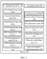
- FIG. 3 shows a system block diagram of a server in accordance with an exemplary embodiment of the present invention.
- a server 300 in accordance with an exemplary embodiment of the present invention includes a terminal determining unit 302 which determines a destination terminal to share a service when a service request sent by any terminal is received or when it is detected that a network-side needs to share the service, a generation unit 304 which generates service network topology structure information corresponding to the service according to the destination terminal, and a network determining unit 306 which determines a hosted network corresponding to the service according to the service network topology structure information.
- the hosted network corresponding to the service can be determined according to the service network topology structure information generated according to the destination terminal, thus the trust and incentive problem in the D2D network can be resolved, security in data sharing can be increased, and cross-layer optimization between a physical domain network and a service domain network can be accomplished.
- the service request includes a service sharing request and a normal service request.
- the system can identify the type of the service request more conveniently, so as to take corresponding actions.
- the terminal determining unit 302 further includes a search unit 302 which searches in databases to determine whether or not a D2D sharing network corresponding to the service exists or whether or not other users launch the same service request or whether or not other users have the same service requirement according to the normal service request when the service request is received from any terminal and the service request is the normal service request, and a first determining unit 3024 which determines the destination terminal according to search results of the search unit 302.
- a search unit 302 which searches in databases to determine whether or not a D2D sharing network corresponding to the service exists or whether or not other users launch the same service request or whether or not other users have the same service requirement according to the normal service request when the service request is received from any terminal and the service request is the normal service request
- a first determining unit 3024 which determines the destination terminal according to search results of the search unit 302.
- the server searches in the databases to determine whether or not a sharing network corresponding to the service exists or whether or not other users have the same service request according to the normal service request, so as to determine whether or not a network can be established to share data.
- the databases include a database of the server and databases of other servers.
- the server can further include a first interaction unit 308 which transmits the normal service request to the other servers, such that the other servers can search in the corresponding databases to determine whether or not a sharing network corresponding to the service exists or whether or not other users launch the same service request or whether or not other users have the same service requirement.
- the first interaction unit 308 further receives search results from the other servers.
- the normal service request can be transmitted to the other servers, and the other servers search in the corresponding databases to find the sharing network corresponding to the service or the same service request of other users, and return the search results to the server.
- the terminal which satisfies the sharing requirement can be found in a greater range, which expands the sharing range.
- the terminal determining unit 302 further includes a first transmission unit 30212 which determines multiple group terminals the interest group of which is the same as that of any terminal when the service request sent by the any terminal is received and the service request is the service sharing request, and transmits a service sharing notification to the multiple group terminals.
- the terminal determining unit 302 further includes a second determining unit 3026 which determines the destination terminal according to service sharing feedback information transmitted by the multiple group terminals.
- the service sharing notification can be transmitted to the multiple group terminals which are in the same interest group, and the service sharing feedback information is received from the group terminals.
- the terminal which agrees sharing is determined as the destination terminal according to the service sharing feedback information. Therefore, security and reliability of data sharing can be increased, the trust problem in the D2D network can be fully considered, and meanwhile data sharing between interest groups can be accomplished.
- the interest group can be an interest group formed according to upper application or subscription data, such as a group in Wechat, QQ, or like.
- the terminal determining unit 302 further includes a second transmission unit 30214 which transmits the service sharing notification to multiple terminals when a service request from any terminal is received and the service request is the service sharing request, wherein the service sharing request includes service description information and access limitation information.
- the terminal determining unit 302 further includes a third determining unit 3028 which determines the destination terminal according to the service sharing feedback information transmitted by the multiple terminals, wherein the service sharing feedback information includes position information of the terminal.
- the any terminal when any terminal wants to share a certain data service, the any terminal can transmit the service sharing notification to multiple terminals simultaneously, and embed its requirements such as the service description information and the access limitation information into the service sharing request.
- the third determining unit 3028 determines the destination terminal which satisfies the requirements of the service requester-side and determines the position information of the destination terminal, wherein, the service description information is used to describe data content to be shared, and the access limitation information is to describe a time range of opening the data sharing service (for example, N hours) and/or condition information of access limitation (for example, credit level>N, particular groups/users allowed to be accessed).
- the service description information is used to describe data content to be shared
- the access limitation information is to describe a time range of opening the data sharing service (for example, N hours) and/or condition information of access limitation (for example, credit level>N, particular groups/users allowed to be accessed).
- the terminal determining unit 302 further includes a third transmission unit 30216 which transmits the service sharing notification to multiple terminals when it is detected that the network-side has a service requirement, wherein the service sharing notification includes service description information and service identifier information.
- the terminal determining unit 302 further includes a fourth determining unit 30210 which determines the destination terminal according to the service sharing feedback information transmitted by the multiple terminals, wherein, the service sharing feedback information includes position information and ability information of the terminal.
- the service sharing notification can be transmitted to multiple terminals of the server and other servers.
- the terminal determines whether or not it is interested in the service sharing according to the service sharing notification, and accordingly returns the service sharing feedback information, and accordingly whether or not the sharing network can be established is determined according to the feedback information.
- the multiple terminals belong to the server and other servers.
- the server further includes a second interaction unit 310 which transmits the service sharing notification to the other servers, such that the other servers transmit the service sharing notification to the corresponding terminals, and the second interaction unit 310 further receives the service sharing feedback information transmitted by the corresponding terminals of the other servers.
- all of the multiple terminals can be from a server, that is the server, and can also be from multiple servers consisted of the server and the other servers.
- the server can further include an identifier defining unit 312 which defines a service sharing identifier for the D2D service, such that the service can be identified according to the service sharing identifier.
- the server can directly identify the sharing service according to the identifier and take corresponding solutions, such that determination of whether or not the service is the sharing service can be avoided, which saves power consumption of user equipment and also reduces operating cost of operators.
- the service network topology structure information includes one of the following or a combination of the following: node position information, node attribute information, and node identifier information of the topology structure.
- the service network topology structure information formed by any one of or a combination of different node position information, node attribute information, and node identifier information has its uniqueness.
- the corresponding particular hosted network is determined according to the service network topology structure information, which contributes to the increase of security of data sharing.
- the node position information such as eNB id, GPS coordinates of the node, indicates the information of the region of the node.
- the node attribute indicates that the node belongs to a data reception node or/and a data source node.
- the node identifier indicates the identity of user equipment, such as IMSI, and so on.
- the server further includes a network establishing unit 314 which directly establishes the determined hosted network and transmits a networking notification to the destination terminal.
- the corresponding hosted network is determined according to the obtained service network topology structure information, and the destination terminal is informed to cause the destination terminal to know the condition of the current access network, which enhances security of network sharing, and solves the trust and incentive problem in the D2D network.
- the server can further includes a recommendation transmission unit 312 which transmits a networking recommendation to the destination terminal after the hosted network corresponding to the service is determined, such that whether or not the hosted network is established is determined according to the networking feedback information of the destination terminal.
- a recommendation transmission unit 312 which transmits a networking recommendation to the destination terminal after the hosted network corresponding to the service is determined, such that whether or not the hosted network is established is determined according to the networking feedback information of the destination terminal.
- the networking recommendation is transmitted to ask for permission of the destination terminal.
- the hosted network is established under the condition of that the destination terminal agrees, which greatly enhances security of the destination terminal.
- the network determining unit further includes an acquisition unit 3062 which acquires a preset physical domain networking rule and a business mode domain networking rule, and determines the hosted network corresponding to the service according to the preset physical domain networking rule, the business mode domain networking rule, and the service network topology structure information.
- the D2D network is established according to the physical domain network, the business mode domain network, and the service domain network, which can accomplish cross-layer optimization of the physical domain network and the service domain network.
- FIG. 4a shows a flow chart of a data transmission method in accordance with an exemplary embodiment of the present invention.
- a data transmission method in accordance with an exemplary embodiment of the present invention includes step 402 of determining a destination terminal to share a service when a service request sent by any terminal is received or when it is detected that a network-side needs to share the service, step 404 of generating service network topology structure information corresponding to the service according to the destination terminal, and step 406 of determining a hosted network corresponding to the service according to the service network topology structure information.
- the hosted network corresponding to the service can be determined according to the service network topology structure information generated according to the destination terminal, thus the trust and incentive problem in D2D networks can be resolved, security in data sharing can be increased, and cross-layer optimization between a physical domain network and a service domain network can be accomplished.
- the service request includes a service sharing request and a normal service request.
- the system can identify the type of the service request more conveniently, so as to take corresponding actions.
- the determining a destination terminal to share a service particularly includes: searching, by the server, in databases to determine whether or not a D2D sharing network corresponding to the service exists or whether or not other users launch the same service request or whether or not other users have the same service requirement according to the normal service request when a service request is received from any terminal and the service request is the normal service request, and determining the destination terminal according to search results.
- the server searches in the databases to determine whether or not a sharing network corresponding to the service exists or whether or not other users have the same service request according to the normal service request, so as to determine whether or not a network can be established to share data.
- the databases include a database of the server and databases of other servers.
- the data transmission method can further include transmitting the normal service request to the other servers, such that the other servers can search in the corresponding databases to determine whether or not a sharing network corresponding to the service exists or whether or not other users launch the same service request or whether or not other users have the same service requirement.
- the data transmission method further includes receiving the search results from the other servers.
- the normal service request can be transmitted to the other servers, and the other servers search in the corresponding databases to find the sharing network corresponding to the service or the same service request of other users, and return the search results to the server.
- the terminal which satisfies the sharing requirement can be found in a greater range, which expands the sharing range.
- the determining a destination terminal to share a service particularly includes: determining multiple group terminals the interest group of which is the same as that of any terminal when a service request sent by the any terminal is received and the service request is the service sharing request, and transmitting a service sharing notification to the multiple group terminals; and determining the destination terminal according to service sharing feedback information transmitted by the multiple group terminals.
- the service sharing notification can be transmitted to the multiple group terminals which are in the same interest group, and the service sharing feedback information is received from the group terminals.
- the terminal which agrees sharing is determined as the destination terminal according to the service sharing feedback information. Therefore, security and reliability of data sharing can be increased, the trust problem in the D2D network can be fully considered, and meanwhile data sharing between interest groups can be accomplished.
- the interest group can be an interest group formed according to upper application or subscription data, such as a group in Wechat, QQ, or like.
- the determining a destination terminal to share a service particularly includes: transmitting the service sharing notification to multiple terminals when a service request from any terminal is received and the service request is the service sharing request, wherein the service sharing request includes service description information and access limitation information.
- the determining a destination terminal to share a service further includes determining the destination terminal according to the service sharing feedback information transmitted by the multiple terminals, wherein, the service sharing feedback information includes position information of the terminal.
- the any terminal when any terminal wants to a share certain data service, the any terminal can transmit the service sharing notification to multiple terminals simultaneously, and embed its requirements such as the service description information and the access limitation information into the service sharing request.
- the third determining unit 3028 determines the destination terminal which satisfies the requirements of the service requester-side and determines the position information of the destination terminal, wherein, the service description information is used to describe data content to be shared, and the access limitation information is to describe a time range of opening the data sharing service (for example, N hours) and/or condition information of access limitation (for example, credit level>N, particular groups/users allowed to be accessed).
- the service description information is used to describe data content to be shared
- the access limitation information is to describe a time range of opening the data sharing service (for example, N hours) and/or condition information of access limitation (for example, credit level>N, particular groups/users allowed to be accessed).
- the determining a destination terminal to share a service particularly includes: transmitting the service sharing notification to multiple terminals when it is detected that the network-side has service requirements, wherein the service sharing notification includes service description information and service identifier information.
- the determining a destination terminal to share a service further includes determining the destination terminal according to the service sharing feedback information transmitted by the multiple terminals, wherein, the service sharing feedback information includes position information and ability information of the terminal.
- the service sharing notification can be transmitted to multiple terminals of the server and other servers.
- the terminal determines whether or not it is interested in the service sharing according to the service sharing notification, and accordingly returns the service sharing feedback information, and accordingly whether or not the sharing network can be established is determined according to the feedback information.
- the multiple terminals belong to the server and other servers.
- the data transmission method further includes transmitting the service sharing notification to the other servers, such that the other servers transmit the service sharing notification to the corresponding terminals, and receiving the service sharing feedback information transmitted by the corresponding terminals of the other servers.
- all of the multiple terminals can be from a server, that is the server, and can also be from multiple servers consisted of the server and the other servers.
- the data transmission method can further include defining a service sharing identifier for the D2D service, such that the service can be identified according to the service sharing identifier.
- the server can directly identify the sharing service according to the identifier and take corresponding solutions, such that determination of whether or not the service is the sharing service can be avoided, which saves power consumption of user equipments and also reduces operating cost of operators.
- the service network topology structure information includes one of the following or a combination of the following: node position information, node attribute information, and node identifier information of the topology structure.
- the service network topology structure information formed by any one of or a combination of different node position information, node attribute information, and node identifier information has its uniqueness.
- the corresponding particular hosted network is determined according to the service network topology structure information, which contributes to the increase of security of data sharing.
- the node position information such as eNB id, GPS coordinates of the node, indicates the information of the region of the node.
- the node attribute indicates that the node belongs to a data reception node or/and a data source node.
- the node identifier indicates the identity of user equipment, such as IMSI, and so on.
- the data transmission method further includes establishing the determined hosted network directly and transmitting a networking notification to the destination terminal.
- the corresponding hosted network is determined according to the obtained service network topology structure information, and the destination terminal is informed to cause the destination terminal to know the condition of the current access network, which enhances security of network sharing, and solves the trust and incentive problem in the D2D network.
- the data transmission method can further include transmitting a networking recommendation to the destination terminal after the hosted network corresponding to the service is determined, such that whether or not the hosted network is established is determined according to the networking feedback information of the destination terminal.
- the networking recommendation is transmitted to ask for permission of the destination terminal.
- the hosted network is established under the condition of that the destination terminal agrees, which greatly enhances security of the destination terminal.
- the data transmission method further includes: acquiring a preset physical domain networking rule and a business mode domain networking rule, and determining the hosted network corresponding to the service according to the preset physical domain networking rule, the business mode domain networking rule, and the service network topology structure information.
- FIG. 4b shows a network structure diagram of a server in accordance with an exemplary embodiment of the present invention.
- the server of the present invention can be referred as a "D2D strategy and management server".
- the D2D strategy and management server can be a physical entity or a logical entity, and can also be enhancement of an independent entity or an existed entity (access network or core network node), and can also be a combination of one or more entities.
- the D2D strategy and management server is independent of the base station, a signaling interface needs to be established between the D2D strategy and management server and the base station.
- the functions of the D2D strategy and management server includes:
- the present invention divides the networking of the service domain network into four modes according to different service requester-sides and different types of service requests. The following will specifically illustrate the modes.
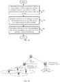
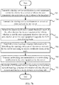
- FIG. 5a and FIG. 5b respectively show a schematic view and a flow chart of the "issue-search" mode of the server in accordance with an exemplary embodiment of the present invention.
- the "issue-search" mode of the server of the embodiments of the present invention includes the following steps.
- step 502 transmitting, by a data source node, a data sharing request to the server.
- the data sharing request includes service description information which is used to describe data content to be shared, and access limitation information which is used to describe a time range of opening the data sharing service (for example, N hours) and/or condition information of access limitation. For example, credit level>N or particular groups/users are allowed to be accessed.
- step 504 defining, by the server, a D2D service sharing identifier for the data sharing service for identifying the D2D sharing service, and storing and maintaining, by the server, the service description information and the access limitation information included in the data sharing request.
- step 506 transmitting, by the server, a service sharing notification to user equipment within the district, such that a potential destination terminal can be searched after the service sharing notification is transmitted by the base station.
- the server can transmit the service sharing request to other servers, and issue the service sharing notification within the districts of other servers.
- the server can transmit service sharing broadcast periodically or once, and the broadcast signaling includes the service description information and the access limitation information.
- step 508 returning, by the terminal which receives the service sharing notification, service sharing feedback information to the server to inform the server whether or not it is interested in receiving the D2D data sharing service. If the terminal is interested in receiving the D2D sharing service, the feedback information carries the position information of the user equipment.
- step 510 forming, by the server, service network topology structure information according to the feedback information.
- the information is used to describe the topology structure of the service network.
- the information may include the node position information, such as eNB id, GPS coordinates of the node, which indicates the information of the region of the node, the node attribute which indicates that the node belongs to a data reception node or/and a data source node, and the node identifier which indicates the identity of the user equipment, such as IMSI, and so on.
- step 512 transmitting, by the server, networking recommendation or a networking notification to the user equipment.
- the server can directly inform the user equipment to establish the D2D network according to the service network topology structure information, and can also transmit recommendation signaling and determine whether or not to establish the D2D network according to the feedback of the user equipment.
- step 514 establishing a D2D hosted network according to the service network topology structure information and the physical domain and business mode domain networking rule.
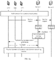
- FIG. 6a and FIG. 6b respectively show a schematic view and a flow chart of the "request-recommendation" mode of the server in accordance with an exemplary embodiment of the present invention.
- the "request-recommendation" mode of the server of the embodiments of the present invention includes the following steps.
- step 602 transmitting, by user equipment, a service request to the server.
- the service request includes position information of the user equipment.
- step 604 searching, by the server, in the database to determine whether or not the D2D sharing network having the same service exists.
- the database of the server can interact with the core network to establish a corresponding relationship between the public service and the D2D sharing service. According to the corresponding relationship, the server can determine whether or not a D2D sharing network corresponding to the service launched by the user equipment exists.
- step 606 transmitting, by the server, the service request to servers of other districts to search in the other districts to find the existed D2D sharing network.
- step 608 establishing, by the server, the service topology structure information for describing the topology structure of the service network according to the database search result and/or search feedback results from other districts.
- the information may include the following information: the node position information, such as eNB id, GPS coordinates of the node, which indicates the information of the region of the node, the node attribute which indicates that the node belongs to a data reception node or/and a data source node, and the node identifier which indicates the identity of the user equipment, such as IMSI, and so on.
- the node position information such as eNB id
- GPS coordinates of the node which indicates the information of the region of the node
- the node attribute which indicates that the node belongs to a data reception node or/and a data source node
- the node identifier which indicates the identity of the user equipment, such as IMSI, and so on.
- step 610 transmitting, by the server, networking recommendation or a networking notification to the user equipment.
- the service can directly inform the user equipment to establish the D2D network according to the service network topology structure information, and can also transmit recommendation signaling and determine whether or not to establish the D2D network according to the feedback of the user equipment
- step 612 establishing a D2D hosted network according to the service network topology structure information and the physical domain and business mode domain networking rule.
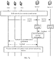
- FIG. 7a and FIG. 7b respectively show a schematic view and a flow chart of the "broadcast-interest" mode of the server in accordance with an exemplary embodiment of the present invention.
- the "broadcast-interest" mode of the server of the embodiments of the present invention includes the following steps.
- step 702 transmitting, by the server, a sharing service notification to user equipment within the district to inform the user equipment that a certain service is about to be launched.
- the message includes a service description message used for describing data content to be shared and also includes a D2D service identifier.
- step 704 transmitting, by the server, the sharing service notification to servers of other districts to search in the other districts to find a potential interest user.
- step 706 returning, by the user equipment, the search result and/or search feedback result of the other districts to inform whether or not the user equipment receives the service and whether or not the user equipment supports the D2D data sharing mode.
- the message may include the information of the position and ability of the user equipment.
- step 708 establishing, by the server, the service topology structure information for describing the topology structure of the service network according to interest feedback results of the users.
- the information may include the following information: the node position information, such as eNB id, GPS coordinates of the node, which indicates the information of the region of the node, the node attribute which indicates that the node belongs to a data reception node or/and a data source node, and the node identifier which indicates the identity of user equipment, such as IMSI, and so on.
- the node position information such as eNB id
- GPS coordinates of the node which indicates the information of the region of the node
- the node attribute which indicates that the node belongs to a data reception node or/and a data source node
- the node identifier which indicates the identity of user equipment, such as IMSI, and so on.
- step 710 transmitting, by the server, networking recommendation or a networking notification to the user equipment.
- the server can directly inform the user equipment to establish the D2D network according to the service network topology structure information, and can also transmit recommendation signaling and determine whether or not to establish the D2D network according to the feedback of the user equipment.
- step 712 establishing a D2D hosted network according to the service network topology structure information and the physical domain and business mode domain networking rule.
- FIG. 8a and FIG. 8b respectively show a schematic view and a flow chart of an interest group of the server in accordance with an exemplary embodiment of the present invention.
- the server of the embodiments of the present invention under the "interest group" mode includes the following steps.
- step 802 forming an interest group by user equipment, and maintaining the information of the position and interest of the users within the interest group by the server.
- the interest information is used for indicating which kind of services the user equipment is interested in or the user equipment is interested in service from which user equipment.
- step 804 launching, by the user equipment, a service sharing request or invitation.
- the service sharing request is used for indicating that the user hopes to share a certain data service within the group.
- the service sharing invitation is used for indicating that the user equipment hopes to launch a certain external service and invites the group users to take part in.
- step 806 transmitting, by the server, the service sharing notification to the user equipment within the group to search a potential interest user.
- step 808 transmitting, by the group users, service sharing feedback to the launching equipment.
- step 810 establishing, by the server, the service topology structure information for describing the topology structure of the service network according to service sharing feedback information.
- the information may include the following information: the node position information, such as eNB id, GPS coordinates of the node, which indicates the information of the region of the node, the node attribute which indicates that the node belongs to a data reception node or/and a data source node, and the node identifier which indicates the identity of a user equipment, such as IMSI, and so on.
- the node position information such as eNB id
- GPS coordinates of the node which indicates the information of the region of the node
- the node attribute which indicates that the node belongs to a data reception node or/and a data source node
- the node identifier which indicates the identity of a user equipment, such as IMSI, and so on.
- step 812 transmitting, by the server, networking recommendation or a networking notification to the user equipment.
- the server can directly inform the user equipment to establish the D2D network according to the service network topology structure information, and can also transmit recommendation signaling and determine whether or not to establish the D2D network according to the feedback of the user equipment
- step 814 establishing a D2D hosted network according to the service network topology structure information and the physical domain and business mode domain networking rule.
Landscapes
- Engineering & Computer Science (AREA)
- Computer Networks & Wireless Communication (AREA)
- Signal Processing (AREA)
- Telephonic Communication Services (AREA)
- Mobile Radio Communication Systems (AREA)
Abstract
Description
- The present invention relates to communication technology field, and particularly to a server and a data transmission method.
- The introduction of device to device (D2D) technology provides technology support for increasing efficiency of use of frequency spectrum, increasing system throughput, reducing consumption of user equipment, and reducing operating cost of operators. The present 3GPP network has already studied the D2D technology, and defines multiple application scenarios of the D2D technology. In the study of the present D2D technology of the network-side, the main concern is the method of establishing a D2D network on the physical layer, for example, how to establish the D2D network between two user equipment.
- The study of the D2D technology in academia provides a future application scenario of the D2D technology (as shown in
FIG. 1 ): combining the D2D technology and P2P to realize D2D LAN data sharing. To a great extent, the scenario can increase efficiency of data sharing and data transmission and reduce the load of the network-side. - However, in the present standardization process of the 3GPP, the main concern is how to establish the D2D between two user equipment, which depends on an assumption of that two user equipment which satisfy the physical establishment condition of the D2D (e.g., the distance is short enough) can realize the D2D, and the authorization and incentive problem of user equipment is not considered. Not only whether or not the user equipment in the D2D is safe and is trustworthy to transmit data is not considered, but also the potential business mode problem (incentive problem) during data transmission is not considered. There is no real business mode which can provide realization and support.
- Therefore, what is needed is a new technology to solve the trust and incentive problem in the D2D network, increase security of data sharing, and accomplish cross-layer optimization between a physical domain network and a service domain network.
- Based on the above problems, a new technical solution is provided, which can solve the trust and incentive problem in a D2D network, increase security of data sharing, and accomplish cross-layer optimization of a physical domain network and a service domain network.
- In view of this, the present invention provides a server which includes a terminal determining unit which determines a destination terminal to share a service when a service request sent by any terminal is received or when it is detected that a network-side needs to share the service, a generation unit which generates service network topology structure information corresponding to the service according to the destination terminal, and a network determining unit which determines a hosted network corresponding to the service according to the service network topology structure information.
- In the technical solution, the hosted network corresponding to the service can be determined according to the service network topology structure information generated according to the destination terminal, thus the trust and incentive problem in the D2D network can be resolved, security in data sharing can be increased, and cross-layer optimization between a physical domain network and a service domain network can be accomplished.
- In the above technical solution, preferably, the service request includes a service sharing request and a normal service request.
- In the technical solution, by dividing the service request into the service sharing request and the normal service request, the system can identify the type of the service request more conveniently, so as to take corresponding actions.
- In the above technical solution, preferably, the terminal determining unit further includes a search unit which searches in databases to determine whether or not a D2D sharing network corresponding to the service exists or whether or not other users launch the same service request or whether or not other users have the same service requirement according to the normal service request when the service request is received from any terminal and the service request is the normal service request, and a first determining unit which determines the destination terminal according to search results of the search unit.
- In the technical solution, when the service request is the normal service request, that is, when a terminal requests a certain data service from the server, the server searches in the databases to determine whether or not a sharing network corresponding to the service exists or whether or not other users have the same service request according to the normal service request, so as to determine whether or not a network can be established to share data.
- In the above technical solution, preferably, the databases include a database of the server and databases of other servers. The server can further include a first interaction unit which transmits the normal service request to the other servers, such that the other servers can search in the corresponding databases to determine whether or not a sharing network corresponding to the service exists or whether or not other users launch the same service request or whether or not other users have the same service requirement. The first interaction unit further receives search results from the other servers.
- In the technical solution, not only the database of one server is searched to find the destination terminal, the normal service request can be transmitted to the other servers, and the other servers search in the corresponding databases to find the sharing network corresponding to the service or the same service request of other users, and return the search results to the server. Thus, by searching in the corresponding databases of multiple servers to find the destination terminal, the terminal which satisfies the sharing requirement can be found in a greater range, which expands the sharing range.
- In the above technical solution, preferably, the terminal determining unit further includes a first transmission unit which determines multiple group terminals the interest group of which is the same as that of any terminal when the service request sent by the any terminal is received and the service request is the service sharing request, and transmits a service sharing notification to the multiple group terminals. The terminal determining unit further includes a second determining unit which determines the destination terminal according to service sharing feedback information transmitted by the multiple group terminals.
- In the technical solution, the service sharing notification can be transmitted to the multiple group terminals which are in the same interest group, and the service sharing feedback information is received from the group terminals. The terminal which agrees sharing is determined as the destination terminal according to the service sharing feedback information. Therefore, security and reliability of data sharing can be increased, the trust problem in the D2D network can be fully considered, and meanwhile data sharing between interest groups can be accomplished. Wherein, the interest group can be an interest group formed according to upper application or subscription data, such as a group in Wechat, QQ, or like.
- In the above technical solution, preferably, the terminal determining unit further includes a second transmission unit which transmits the service sharing notification to multiple terminals when a service request from any terminal is received and the service request is the service sharing request, wherein the service sharing request includes service description information and access limitation information. The terminal determining unit further includes a third determining unit which determines the destination terminal according to the service sharing feedback information transmitted by the multiple terminals, wherein the service sharing feedback information includes position information of the terminal.
- In the technical solution, when any terminal wants to share a certain data service, the any terminal can transmit the service sharing notification to multiple terminals simultaneously, and embed its requirements such as the service description information and the access limitation information into the service sharing request. The third determining unit determines the destination terminal which satisfies the requirements of the service requester-side and determines the position information of the destination terminal, wherein, the service description information is used to describe data content to be shared, and the access limitation information is to describe a time range of opening the data sharing service (for example, N hours) and/or condition information of access limitation (for example, credit level>N, particular groups/users allowed to be accessed). By doing so, cross-layer optimization between the physical domain network and the service domain network is accomplished. Furthermore, by facing to more terminals, efficiency of data sharing and transmission can also be increased.
- In the above technical solution, preferably, the terminal determining unit further includes a third transmission unit which transmits the service sharing notification to multiple terminals when it is detected that the network-side has a service requirement, wherein the service sharing notification includes service description information and service identifier information. The terminal determining unit further includes a fourth determining unit which determines the destination terminal according to the service sharing feedback information transmitted by the multiple terminals, wherein, the service sharing feedback information includes position information and ability information of the terminal.
- In the technical solution, when the network-side has a service requirement, the service sharing notification can be transmitted to multiple terminals of the server and other servers. The terminal determines whether or not it is interested in the service sharing according to the service sharing notification, and accordingly returns the service sharing feedback information, and accordingly whether or not the sharing network can be established is determined according to the feedback information.
- In the above technical solution, preferably, the multiple terminals belong to the server and other servers. The server further includes a second interaction unit which transmits the service sharing notification to the other servers, such that the other servers transmit the service sharing notification to the corresponding terminals, and the second interaction unit further receives the service sharing feedback information transmitted by the corresponding terminals of the other servers.
- In the technical solution, all of the multiple terminals can be from a server, that is the server, and can also be from multiple servers consisted of the server and the other servers. By doing so, by transmitting the data sharing notification to the terminals of the multiple servers, the sharing range is expanded.
- In the above technical solution, preferably, the server can further include an identifier defining unit which defines a service sharing identifier for the D2D service, such that the service can be identified according to the service sharing identifier.
- In the technical solution, by defining an identifier for the sharing service, the server can directly identify the sharing service according to the identifier and take corresponding solutions, such that determination of whether or not the service is the sharing service can be avoided, which saves power consumption of user equipment and also reduces operating cost of operators.
- In the above technical solution, preferably, the service network topology structure information includes one of the following or a combination of the following: node position information, node attribute information, and node identifier information of the topology structure.
- In the technical solution, the service network topology structure information formed by any one of or a combination of different node position information, node attribute information, and node identifier information has its uniqueness. The corresponding particular hosted network is determined according to the service network topology structure information, which contributes to the increase of security of data sharing. Wherein, the node position information, such as eNB id, GPS coordinates of the node, indicates the information of the region of the node. The node attribute indicates that the node belongs to a data reception node or/and a data source node. The node identifier indicates the identity of user equipment, such as IMSI, and so on.
- In the above technical solution, preferably, the server further includes a network establishing unit which directly establishes the determined hosted network and transmits a networking notification to the destination terminal.
- In the technical solution, the corresponding hosted network is determined according to the obtained service network topology structure information, and the destination terminal is informed to cause the destination terminal to know the condition of the current access network, which enhances security of network sharing, and solves the trust and incentive problem in the D2D network.
- In the above technical solution, preferably, the server can further include a recommendation transmission unit which transmits a networking recommendation to the destination terminal after the hosted network corresponding to the service is determined, such that whether or not the hosted network is established is determined according to the networking feedback information of the destination terminal.
- In the technical solution, after the hosted network is determined, the networking recommendation is transmitted to ask for permission of the destination terminal. The hosted network is established under the condition of that the destination terminal agrees, which greatly enhances security of the destination terminal.
- In the above technical solution, preferably, the network determining unit further includes an acquisition unit which acquires a preset physical domain networking rule and a business mode domain networking rule, and determines the hosted network corresponding to the service according to the preset physical domain networking rule, the business mode domain networking rule, and the service network topology structure information.
- In the technical solution, the D2D network is established according to the physical domain network, the business mode domain network, and the service domain network, which can accomplish cross-layer optimization of the physical domain network and the service domain network.
- According to another aspect of the present invention, the present invention further provides a data transmission method which includes determining a destination terminal to share a service when a service request sent by any terminal is received or when it is detected that a network-side needs to share the service, generating service network topology structure information corresponding to the service according to the destination terminal, and determining a hosted network corresponding to the service according to the service network topology structure information.
- In the technical solution, the hosted network corresponding to the service can be determined according to the service network topology structure information generated according to the destination terminal, thus the trust and incentive problem in D2D networks can be resolved, security in data sharing can be increased, and cross-layer optimization between a physical domain network and a service domain network can be accomplished.
- In the above technical solution, preferably, the service request includes a service sharing request and a normal service request.
- In the technical solution, by dividing the service request into the service sharing request and the normal service request, the system can identify the type of the service request more conveniently, so as to take corresponding actions.
- In the technical solution, preferably, the determining the destination terminal to share the service particularly includes: searching, by the server, in databases to determine whether or not a D2D sharing network corresponding to the service exists or whether or not other users launch the same service request or whether or not other users have the same service requirement according to the normal service request when a service request is received from any terminal and the service request is the normal service request, and determining the destination terminal according to search results.
- In the technical solution, when the service request is the normal service request, that is, when a terminal requests a certain data service from the server, the server searches in the databases to determine whether or not a sharing network corresponding to the service exists or whether or not other users have the same service request according to the normal service request, so as to determine whether or not a network can be established to share data.
- In the above technical solution, preferably, the databases include a database of the server and databases of other servers. The data transmission method can further include transmitting the normal service request to the other servers, such that the other servers can search in the corresponding databases to determine whether or not a sharing network corresponding to the service exists or whether or not other users launch the same service request or whether or not other users have the same service requirement. The data transmission method further include receiving the search results from the other servers.
- In the technical solution, not only the database of one server is searched to find the destination terminal, the normal service request can be transmitted to the other servers, and the other servers search in the corresponding databases to find the sharing network corresponding to the service or the same service request of other users, and return the search results to the server. Thus, by searching in the corresponding databases of multiple servers to find the destination terminal, the terminal which satisfies the sharing requirement can be found in a greater range, which expands the sharing range.
- In the above technical solution, preferably, the determining the destination terminal to share the service particularly includes: determining multiple group terminals the interest group of which is the same as that of any terminal when a service request sent by the any terminal is received and the service request is the service sharing request, and transmitting a service sharing notification to the multiple group terminals; and determining the destination terminal according to service sharing feedback information transmitted by the multiple group terminals.
- In the technical solution, the service sharing notification can be transmitted to the multiple group terminals which are in the same interest group, and the service sharing feedback information is received from the group terminals. The terminal which agrees sharing is determined as the destination terminal according to the service sharing feedback information. Therefore, security and reliability of data sharing can be increased, the trust problem in the D2D network can be fully considered, and meanwhile data sharing between interest groups can be accomplished. Wherein, the interest group can be an interest group formed according to upper application or subscription data, such as a group in Wechat, QQ, or like.
- In the above technical solution, preferably, the determining the destination terminal to share the service particularly includes: transmitting the service sharing notification to multiple terminals when a service request from any terminal is received and the service request is the service sharing request, wherein the service sharing request includes service description information and access limitation information. The determining a destination terminal to share a service further includes determining the destination terminal according to the service sharing feedback information transmitted by the multiple terminals, wherein, the service sharing feedback information includes position information of the terminal.
- In the technical solution, when any terminal wants to share a certain data service, the any terminal can transmit the service sharing notification to multiple terminals simultaneously, and embed its requirements such as the service description information and the access limitation information into the service sharing request. The third determining unit determines the destination terminal which satisfies the requirements of the service requester-side and determines the position information of the destination terminal, wherein, the service description information is used to describe data content to be shared, and the access limitation information is to describe a time range of opening the data sharing service (for example, N hours) and/or condition information of access limitation (for example, credit level>N, particular groups/users allowed to be accessed). By doing so, cross-layer optimization between the physical domain network and the service domain network is accomplished. Furthermore, by facing to more terminals, efficiency of data sharing and transmission can also be increased.
- In the above technical solution, preferably, the determining the destination terminal to share the service particularly includes: transmitting the service sharing notification to multiple terminals when it is detected that the network-side has a service requirement, wherein the service sharing notification includes service description information and service identifier information. The determining a destination terminal to share a service further includes determining the destination terminal according to the service sharing feedback information transmitted by the multiple terminals, wherein, the service sharing feedback information includes position information and ability information of the terminal.
- In the technical solution, when the network-side has a service requirement, the service sharing notification can be transmitted to multiple terminals of the server and other servers. The terminal determines whether or not it is interested in the service sharing according to the service sharing notification, and accordingly returns the service sharing feedback information, and accordingly whether or not the sharing network can be established is determined according to the feedback information.
- In the above technical solution, preferably, the multiple terminals belong to the server and other servers. The data transmission method further includes transmitting the service sharing notification to the other servers, such that the other servers transmit the service sharing notification to the corresponding terminals. The data transmission method further includes receiving the service sharing feedback information transmitted by the corresponding terminals of the other servers.
- In the technical solution, all of the multiple terminals can be from a server, that is the server, and can also be from multiple servers consisted of the server and the other servers. By doing so, by transmitting the data sharing notification to the terminals of the multiple servers, the sharing range is expanded.
- In the above technical solution, preferably, the data transmission method can further include defining a service sharing identifier for the D2D service, such that the service can be identified according to the service sharing identifier.
- In the technical solution, by defining an identifier for the sharing service, the server can directly identify the sharing service according to the identifier and take corresponding solutions, such that determination of whether or not the service is the sharing service can be avoided, which saves power consumption of user equipment and also reduces operating cost of operators.
- In the above technical solution, preferably, the service network topology structure information includes one of the following or a combination of the following: node position information, node attribute information, and node identifier information of the topology structure.
- In the technical solution, the service network topology structure information formed by any one of or a combination of different node position information, node attribute information, and node identifier information has its uniqueness. The corresponding particular hosted network is determined according to the service network topology structure information, which contributes to the increase of security of data sharing. Wherein, the node position information, such as eNB id, GPS coordinates of the node, indicates the information of the region of the node. The node attribute indicates that the node belongs to a data reception node or/and a data source node. The node identifier indicates the identity of user equipment, such as IMSI, and so on.
- In the above technical solution, preferably, the data transmission method further includes establishing the determined hosted network directly and transmitting a networking notification to the destination terminal.
- In the technical solution, the corresponding hosted network is determined according to the obtained service network topology structure information, and the destination terminal is informed to cause the destination terminal to know the condition of the current access network, which enhances security of network sharing, and solves the trust and incentive problem in the D2D network.
- In the above technical solution, preferably, the data transmission method can further include transmitting a networking recommendation to the destination terminal after the hosted network corresponding to the service is determined, such that whether or not the hosted network is established is determined according to the networking feedback information of the destination terminal.
- In the technical solution, after the hosted network is determined, the networking recommendation is transmitted to ask for permission of the destination terminal. The hosted network is established under the condition of that the destination terminal agrees, which greatly enhances security of the destination terminal.
- In the above technical solution, preferably, the data transmission method further includes: acquiring a preset physical domain networking rule and a business mode domain networking rule, and determining the hosted network corresponding to the service according to the preset physical domain networking rule, the business mode domain networking rule, and the service network topology structure information.
- Through the above technical solution, the trust and incentive problem in a D2D network can be solved, security of data sharing can be increased, and cross-layer optimization of a physical domain network and a service domain network can be accomplished.
-
-
FIG. 1 shows an assumed application scenario of device to device (D2D) of the present technology. -
FIG. 2 shows a model of a D2D network in accordance with an exemplary embodiment of the present invention. -
FIG. 3 shows a system block diagram of a server in accordance with an exemplary embodiment of the present invention. -
FIG. 4a shows a flow chart of a data transmission method in accordance with an exemplary embodiment of the present invention. -
FIG. 4b shows a network structure diagram of a data transmission method in accordance with an exemplary embodiment of the present invention. -
FIG. 5a shows a schematic diagram of an "issue-search" mode of the server in accordance with an exemplary embodiment of the present invention. -
FIG. 5b shows a flow chart under the "issue-search" mode of the server in accordance with an exemplary embodiment of the present invention. -
FIG. 6a shows a schematic diagram of a "request-recommendation" mode of the server in accordance with an exemplary embodiment of the present invention. -
FIG. 6b shows a flow chart under the "request-recommendation" mode of the server in accordance with an exemplary embodiment of the present invention. -
FIG. 7a shows a schematic diagram of a "broadcast-interest" mode of the server in accordance with an exemplary embodiment of the present invention. -
FIG. 7b shows a flow chart under the "broadcast-interest" mode of the server in accordance with an exemplary embodiment of the present invention. -
FIG. 8a shows a schematic diagram of an "interest group" mode of the server in accordance with an exemplary embodiment of the present invention. -
FIG. 8b shows a flow chart under the "interest group" mode of the server in accordance with an exemplary embodiment of the present invention. - To understand the above-mentioned purposes, features and advantages of the present disclosure more clearly, the present disclosure will be further described in detail below in combination with the accompanying drawings and the specific implementations. It should be noted that, the embodiments of the present application and the features in the embodiments may be combined with one another without conflicts.
- Many specific details will be described below for sufficiently understanding the present disclosure. However, the present disclosure may also be implemented by adopting other manners different from those described herein. Accordingly, the protection scope of the present invention is not limited by the specific embodiments disclosed below.
-
FIG. 2 shows a model of a D2D network in accordance with an embodiment of the present invention. - As shown in
FIG. 2 , a D2D network in accordance with an exemplary embodiment of the present invention, that is aD2D network 208 is consisted of aphysical domain network 202, a business mode domain network 204, and aservice domain network 206. Said three network domains describe a D2D network establishment manner from physical connection, business modes, and upper application structures, respectively. Wherein, thephysical domain network 202 establishes a bottom layer D2D network which satisfies certain error rate and time-delay requirements according to physical characteristics of D2D nodes. The business mode domain network 204 controls access of thephysical domain network 202 and selects nodes for thephysical domain network 202 according to defined business mode domain limitation characteristics, e.g., credit and reciprocal principles, so as to form a hosted network which satisfies a certain business mode. Theservice domain network 206 establishes a logic connection network between a data source node and a reception destination node according to existed service relationships. -
FIG. 3 shows a system block diagram of a server in accordance with an exemplary embodiment of the present invention. - As shown in
FIG. 3 , aserver 300 in accordance with an exemplary embodiment of the present invention includes aterminal determining unit 302 which determines a destination terminal to share a service when a service request sent by any terminal is received or when it is detected that a network-side needs to share the service, ageneration unit 304 which generates service network topology structure information corresponding to the service according to the destination terminal, and anetwork determining unit 306 which determines a hosted network corresponding to the service according to the service network topology structure information. - In the technical solution, the hosted network corresponding to the service can be determined according to the service network topology structure information generated according to the destination terminal, thus the trust and incentive problem in the D2D network can be resolved, security in data sharing can be increased, and cross-layer optimization between a physical domain network and a service domain network can be accomplished.
- In the above technical solution, preferably, the service request includes a service sharing request and a normal service request.
- In the technical solution, by dividing the service request into the service sharing request and the normal service request, the system can identify the type of the service request more conveniently, so as to take corresponding actions.
- In the above technical solution, preferably, the
terminal determining unit 302 further includes asearch unit 302 which searches in databases to determine whether or not a D2D sharing network corresponding to the service exists or whether or not other users launch the same service request or whether or not other users have the same service requirement according to the normal service request when the service request is received from any terminal and the service request is the normal service request, and a first determiningunit 3024 which determines the destination terminal according to search results of thesearch unit 302. - In the technical solution, when the service request is the normal service request, that is, when a terminal requests a certain data service from the server, the server searches in the databases to determine whether or not a sharing network corresponding to the service exists or whether or not other users have the same service request according to the normal service request, so as to determine whether or not a network can be established to share data.
- In the above technical solution, preferably, the databases include a database of the server and databases of other servers. The server can further include a
first interaction unit 308 which transmits the normal service request to the other servers, such that the other servers can search in the corresponding databases to determine whether or not a sharing network corresponding to the service exists or whether or not other users launch the same service request or whether or not other users have the same service requirement. Thefirst interaction unit 308 further receives search results from the other servers. - In the technical solution, not only the database of one server is searched to find the destination terminal, the normal service request can be transmitted to the other servers, and the other servers search in the corresponding databases to find the sharing network corresponding to the service or the same service request of other users, and return the search results to the server. Thus, by searching in the corresponding databases of multiple servers to find the destination terminal, the terminal which satisfies the sharing requirement can be found in a greater range, which expands the sharing range.
- In the above technical solution, preferably, the
terminal determining unit 302 further includes afirst transmission unit 30212 which determines multiple group terminals the interest group of which is the same as that of any terminal when the service request sent by the any terminal is received and the service request is the service sharing request, and transmits a service sharing notification to the multiple group terminals. Theterminal determining unit 302 further includes a second determiningunit 3026 which determines the destination terminal according to service sharing feedback information transmitted by the multiple group terminals. - In the technical solution, the service sharing notification can be transmitted to the multiple group terminals which are in the same interest group, and the service sharing feedback information is received from the group terminals. The terminal which agrees sharing is determined as the destination terminal according to the service sharing feedback information. Therefore, security and reliability of data sharing can be increased, the trust problem in the D2D network can be fully considered, and meanwhile data sharing between interest groups can be accomplished. Wherein, the interest group can be an interest group formed according to upper application or subscription data, such as a group in Wechat, QQ, or like.
- In the above technical solution, preferably, the
terminal determining unit 302 further includes asecond transmission unit 30214 which transmits the service sharing notification to multiple terminals when a service request from any terminal is received and the service request is the service sharing request, wherein the service sharing request includes service description information and access limitation information. Theterminal determining unit 302 further includes a third determiningunit 3028 which determines the destination terminal according to the service sharing feedback information transmitted by the multiple terminals, wherein the service sharing feedback information includes position information of the terminal. - In the technical solution, when any terminal wants to share a certain data service, the any terminal can transmit the service sharing notification to multiple terminals simultaneously, and embed its requirements such as the service description information and the access limitation information into the service sharing request. The third determining
unit 3028 determines the destination terminal which satisfies the requirements of the service requester-side and determines the position information of the destination terminal, wherein, the service description information is used to describe data content to be shared, and the access limitation information is to describe a time range of opening the data sharing service (for example, N hours) and/or condition information of access limitation (for example, credit level>N, particular groups/users allowed to be accessed). By doing so, cross-layer optimization between the physical domain network and the service domain network is accomplished. Furthermore, by facing to more terminals, efficiency of data sharing and transmission can also be increased. - In the above technical solution, preferably, the
terminal determining unit 302 further includes athird transmission unit 30216 which transmits the service sharing notification to multiple terminals when it is detected that the network-side has a service requirement, wherein the service sharing notification includes service description information and service identifier information. Theterminal determining unit 302 further includes a fourth determining unit 30210 which determines the destination terminal according to the service sharing feedback information transmitted by the multiple terminals, wherein, the service sharing feedback information includes position information and ability information of the terminal. - In the technical solution, when the network-side has a service requirement, the service sharing notification can be transmitted to multiple terminals of the server and other servers. The terminal determines whether or not it is interested in the service sharing according to the service sharing notification, and accordingly returns the service sharing feedback information, and accordingly whether or not the sharing network can be established is determined according to the feedback information.
- In the above technical solution, preferably, the multiple terminals belong to the server and other servers. The server further includes a
second interaction unit 310 which transmits the service sharing notification to the other servers, such that the other servers transmit the service sharing notification to the corresponding terminals, and thesecond interaction unit 310 further receives the service sharing feedback information transmitted by the corresponding terminals of the other servers. - In the technical solution, all of the multiple terminals can be from a server, that is the server, and can also be from multiple servers consisted of the server and the other servers. By doing so, by transmitting the data sharing notification to the terminals of the multiple servers, the sharing range is expanded.
- In the above technical solution, preferably, the server can further include an
identifier defining unit 312 which defines a service sharing identifier for the D2D service, such that the service can be identified according to the service sharing identifier. - In the technical solution, by defining an identifier for the sharing service, the server can directly identify the sharing service according to the identifier and take corresponding solutions, such that determination of whether or not the service is the sharing service can be avoided, which saves power consumption of user equipment and also reduces operating cost of operators.
- In the above technical solution, preferably, the service network topology structure information includes one of the following or a combination of the following: node position information, node attribute information, and node identifier information of the topology structure.
- In the technical solution, the service network topology structure information formed by any one of or a combination of different node position information, node attribute information, and node identifier information has its uniqueness. The corresponding particular hosted network is determined according to the service network topology structure information, which contributes to the increase of security of data sharing. Wherein, the node position information, such as eNB id, GPS coordinates of the node, indicates the information of the region of the node. The node attribute indicates that the node belongs to a data reception node or/and a data source node. The node identifier indicates the identity of user equipment, such as IMSI, and so on.
- In the above technical solution, preferably, the server further includes a
network establishing unit 314 which directly establishes the determined hosted network and transmits a networking notification to the destination terminal. - In the technical solution, the corresponding hosted network is determined according to the obtained service network topology structure information, and the destination terminal is informed to cause the destination terminal to know the condition of the current access network, which enhances security of network sharing, and solves the trust and incentive problem in the D2D network.
- In the above technical solution, preferably, the server can further includes a
recommendation transmission unit 312 which transmits a networking recommendation to the destination terminal after the hosted network corresponding to the service is determined, such that whether or not the hosted network is established is determined according to the networking feedback information of the destination terminal. - In the technical solution, after the hosted network is determined, the networking recommendation is transmitted to ask for permission of the destination terminal. The hosted network is established under the condition of that the destination terminal agrees, which greatly enhances security of the destination terminal.
- In the above technical solution, preferably, the network determining unit further includes an
acquisition unit 3062 which acquires a preset physical domain networking rule and a business mode domain networking rule, and determines the hosted network corresponding to the service according to the preset physical domain networking rule, the business mode domain networking rule, and the service network topology structure information. - In the technical solution, the D2D network is established according to the physical domain network, the business mode domain network, and the service domain network, which can accomplish cross-layer optimization of the physical domain network and the service domain network.
-
FIG. 4a shows a flow chart of a data transmission method in accordance with an exemplary embodiment of the present invention. - As shown in
FIG. 4a , a data transmission method in accordance with an exemplary embodiment of the present invention includesstep 402 of determining a destination terminal to share a service when a service request sent by any terminal is received or when it is detected that a network-side needs to share the service, step 404 of generating service network topology structure information corresponding to the service according to the destination terminal, and step 406 of determining a hosted network corresponding to the service according to the service network topology structure information. - In the technical solution, the hosted network corresponding to the service can be determined according to the service network topology structure information generated according to the destination terminal, thus the trust and incentive problem in D2D networks can be resolved, security in data sharing can be increased, and cross-layer optimization between a physical domain network and a service domain network can be accomplished.
- In the above technical solution, preferably, the service request includes a service sharing request and a normal service request.
- In the technical solution, by dividing the service request into the service sharing request and the normal service request, the system can identify the type of the service request more conveniently, so as to take corresponding actions.
- In the technical solution, preferably, the determining a destination terminal to share a service particularly includes: searching, by the server, in databases to determine whether or not a D2D sharing network corresponding to the service exists or whether or not other users launch the same service request or whether or not other users have the same service requirement according to the normal service request when a service request is received from any terminal and the service request is the normal service request, and determining the destination terminal according to search results.
- In the technical solution, when the service request is the normal service request, that is, when a terminal requests a certain data service from the server, the server searches in the databases to determine whether or not a sharing network corresponding to the service exists or whether or not other users have the same service request according to the normal service request, so as to determine whether or not a network can be established to share data.
- In the above technical solution, preferably, the databases include a database of the server and databases of other servers. The data transmission method can further include transmitting the normal service request to the other servers, such that the other servers can search in the corresponding databases to determine whether or not a sharing network corresponding to the service exists or whether or not other users launch the same service request or whether or not other users have the same service requirement. The data transmission method further includes receiving the search results from the other servers.
- In the technical solution, not only the database of one server is searched to find the destination terminal, the normal service request can be transmitted to the other servers, and the other servers search in the corresponding databases to find the sharing network corresponding to the service or the same service request of other users, and return the search results to the server. Thus, by searching in the corresponding databases of multiple servers to find the destination terminal, the terminal which satisfies the sharing requirement can be found in a greater range, which expands the sharing range.
- In the above technical solution, preferably, the determining a destination terminal to share a service particularly includes: determining multiple group terminals the interest group of which is the same as that of any terminal when a service request sent by the any terminal is received and the service request is the service sharing request, and transmitting a service sharing notification to the multiple group terminals; and determining the destination terminal according to service sharing feedback information transmitted by the multiple group terminals.
- In the technical solution, the service sharing notification can be transmitted to the multiple group terminals which are in the same interest group, and the service sharing feedback information is received from the group terminals. The terminal which agrees sharing is determined as the destination terminal according to the service sharing feedback information. Therefore, security and reliability of data sharing can be increased, the trust problem in the D2D network can be fully considered, and meanwhile data sharing between interest groups can be accomplished. Wherein, the interest group can be an interest group formed according to upper application or subscription data, such as a group in Wechat, QQ, or like.
- In the above technical solution, preferably, the determining a destination terminal to share a service particularly includes: transmitting the service sharing notification to multiple terminals when a service request from any terminal is received and the service request is the service sharing request, wherein the service sharing request includes service description information and access limitation information. The determining a destination terminal to share a service further includes determining the destination terminal according to the service sharing feedback information transmitted by the multiple terminals, wherein, the service sharing feedback information includes position information of the terminal.
- In the technical solution, when any terminal wants to a share certain data service, the any terminal can transmit the service sharing notification to multiple terminals simultaneously, and embed its requirements such as the service description information and the access limitation information into the service sharing request. The third determining
unit 3028 determines the destination terminal which satisfies the requirements of the service requester-side and determines the position information of the destination terminal, wherein, the service description information is used to describe data content to be shared, and the access limitation information is to describe a time range of opening the data sharing service (for example, N hours) and/or condition information of access limitation (for example, credit level>N, particular groups/users allowed to be accessed). By doing so, cross-layer optimization between the physical domain network and the service domain network is accomplished. Furthermore, by facing to more terminals, efficiency of data sharing and transmission can also be increased. - In the above technical solution, preferably, the determining a destination terminal to share a service particularly includes: transmitting the service sharing notification to multiple terminals when it is detected that the network-side has service requirements, wherein the service sharing notification includes service description information and service identifier information. The determining a destination terminal to share a service further includes determining the destination terminal according to the service sharing feedback information transmitted by the multiple terminals, wherein, the service sharing feedback information includes position information and ability information of the terminal.
- In the technical solution, when the network-side has service requirements, the service sharing notification can be transmitted to multiple terminals of the server and other servers. The terminal determines whether or not it is interested in the service sharing according to the service sharing notification, and accordingly returns the service sharing feedback information, and accordingly whether or not the sharing network can be established is determined according to the feedback information.
- In the above technical solution, preferably, the multiple terminals belong to the server and other servers. The data transmission method further includes transmitting the service sharing notification to the other servers, such that the other servers transmit the service sharing notification to the corresponding terminals, and receiving the service sharing feedback information transmitted by the corresponding terminals of the other servers.
- In the technical solution, all of the multiple terminals can be from a server, that is the server, and can also be from multiple servers consisted of the server and the other servers. By doing so, by transmitting the data sharing notification to the terminals of the multiple servers, the sharing range is expanded.
- In the above technical solution, preferably, the data transmission method can further include defining a service sharing identifier for the D2D service, such that the service can be identified according to the service sharing identifier.
- In the technical solution, by defining an identifier for the sharing service, the server can directly identify the sharing service according to the identifier and take corresponding solutions, such that determination of whether or not the service is the sharing service can be avoided, which saves power consumption of user equipments and also reduces operating cost of operators.
- In the above technical solution, preferably, the service network topology structure information includes one of the following or a combination of the following: node position information, node attribute information, and node identifier information of the topology structure.
- In the technical solution, the service network topology structure information formed by any one of or a combination of different node position information, node attribute information, and node identifier information has its uniqueness. The corresponding particular hosted network is determined according to the service network topology structure information, which contributes to the increase of security of data sharing. Wherein, the node position information, such as eNB id, GPS coordinates of the node, indicates the information of the region of the node. The node attribute indicates that the node belongs to a data reception node or/and a data source node. The node identifier indicates the identity of user equipment, such as IMSI, and so on.
- In the above technical solution, preferably, the data transmission method further includes establishing the determined hosted network directly and transmitting a networking notification to the destination terminal.
- In the technical solution, the corresponding hosted network is determined according to the obtained service network topology structure information, and the destination terminal is informed to cause the destination terminal to know the condition of the current access network, which enhances security of network sharing, and solves the trust and incentive problem in the D2D network.
- In the above technical solution, preferably, the data transmission method can further include transmitting a networking recommendation to the destination terminal after the hosted network corresponding to the service is determined, such that whether or not the hosted network is established is determined according to the networking feedback information of the destination terminal.
- In the technical solution, after the hosted network is determined, the networking recommendation is transmitted to ask for permission of the destination terminal. The hosted network is established under the condition of that the destination terminal agrees, which greatly enhances security of the destination terminal.
- In the above technical solution, preferably, the data transmission method further includes: acquiring a preset physical domain networking rule and a business mode domain networking rule, and determining the hosted network corresponding to the service according to the preset physical domain networking rule, the business mode domain networking rule, and the service network topology structure information.
-
FIG. 4b shows a network structure diagram of a server in accordance with an exemplary embodiment of the present invention. - As shown in
FIG. 4b , to realize D2D network (D2D LAN) data management and strategy control function, the server of the present invention can be referred as a "D2D strategy and management server". - The D2D strategy and management server can be a physical entity or a logical entity, and can also be enhancement of an independent entity or an existed entity (access network or core network node), and can also be a combination of one or more entities.
- If the D2D strategy and management server is independent of the base station, a signaling interface needs to be established between the D2D strategy and management server and the base station.
- There is a signaling interaction interface between the D2D strategy and management servers.
- There is a signaling interaction interface between the D2D strategy and management server and the core network (for example, HSS/HLR).
- The functions of the D2D strategy and management server includes:
- (1) managing and assigning a service identifier of a service within a district:
Defining a D2D service identifier for a certain D2D data sharing service for identifying different services of the hosted network; inquiring the service requested by a user equipment to find the corresponding D2D service identifier; and managing, maintaining, and issuing a data sharing request. - (2) service domain network networking management:
- The present invention divides the networking of the service domain network into four modes according to different service requester-sides and different types of service requests. The following will specifically illustrate the modes.
- 1. Under an "issue-search" mode, the server is used to maintain a "data sharing request" issued by an UE, define a D2D service identifier for it, and transmit a "service sharing notification" (including the D2D service identifier and the service description information) to cells within the district, and search a potential interest user equipment (UE). The server can also transmit the "data sharing request" to other servers to search a potential interest UE outside of the region.
- 2. Under a "request-recommendation" mode, the server searches in the database according to the service request transmitted by the UE to determine whether or not a D2D sharing network having the same service exists at current time and inquire the user equipment whether or not the D2D sharing network can be established to receive data.
- 3. Under a "broadcast-interest" mode, a service identifier is defined, and the identifier and service description information are transmitted to cells within/out of the district to search a potential interest UE.
- 4. Under an "interest group" mode, the database of interest groups within the district is updated and maintained, and interacts with servers of other districts to form a wide area group. The business mode domain data management (the function can be separated and arranged at the base station side) is in charge of interaction with the core network, and maintains and updates a UE credit level black and white list within the district (including relay selection and networking optimization algorithm).
-
FIG. 5a andFIG. 5b respectively show a schematic view and a flow chart of the "issue-search" mode of the server in accordance with an exemplary embodiment of the present invention. - As shown in
FIG. 5a andFIG. 5b , under the scenario of that the terminal hopes to issue a sharing data service through the mobile network, the "issue-search" mode of the server of the embodiments of the present invention includes the following steps. - In
step 502, transmitting, by a data source node, a data sharing request to the server. The data sharing request includes service description information which is used to describe data content to be shared, and access limitation information which is used to describe a time range of opening the data sharing service (for example, N hours) and/or condition information of access limitation. For example, credit level>N or particular groups/users are allowed to be accessed. - In
step 504, defining, by the server, a D2D service sharing identifier for the data sharing service for identifying the D2D sharing service, and storing and maintaining, by the server, the service description information and the access limitation information included in the data sharing request. - In
step 506, transmitting, by the server, a service sharing notification to user equipment within the district, such that a potential destination terminal can be searched after the service sharing notification is transmitted by the base station. Wherein, the server can transmit the service sharing request to other servers, and issue the service sharing notification within the districts of other servers. The server can transmit service sharing broadcast periodically or once, and the broadcast signaling includes the service description information and the access limitation information. - In
step 508, returning, by the terminal which receives the service sharing notification, service sharing feedback information to the server to inform the server whether or not it is interested in receiving the D2D data sharing service. If the terminal is interested in receiving the D2D sharing service, the feedback information carries the position information of the user equipment. - In
step 510, forming, by the server, service network topology structure information according to the feedback information. The information is used to describe the topology structure of the service network. The information may include the node position information, such as eNB id, GPS coordinates of the node, which indicates the information of the region of the node, the node attribute which indicates that the node belongs to a data reception node or/and a data source node, and the node identifier which indicates the identity of the user equipment, such as IMSI, and so on. - In
step 512, transmitting, by the server, networking recommendation or a networking notification to the user equipment. The server can directly inform the user equipment to establish the D2D network according to the service network topology structure information, and can also transmit recommendation signaling and determine whether or not to establish the D2D network according to the feedback of the user equipment. - In
step 514, establishing a D2D hosted network according to the service network topology structure information and the physical domain and business mode domain networking rule. -
FIG. 6a andFIG. 6b respectively show a schematic view and a flow chart of the "request-recommendation" mode of the server in accordance with an exemplary embodiment of the present invention. - As shown in
FIG. 6a andFIG. 6b , under the scenario of that the server determines whether or not to establish the D2D sharing network according to whether or not other clients which have the similar request exists when the user equipment requests the data service, the "request-recommendation" mode of the server of the embodiments of the present invention includes the following steps. - In
step 602, transmitting, by user equipment, a service request to the server. The service request includes position information of the user equipment. - In
step 604, searching, by the server, in the database to determine whether or not the D2D sharing network having the same service exists. The database of the server can interact with the core network to establish a corresponding relationship between the public service and the D2D sharing service. According to the corresponding relationship, the server can determine whether or not a D2D sharing network corresponding to the service launched by the user equipment exists. - In
step 606, transmitting, by the server, the service request to servers of other districts to search in the other districts to find the existed D2D sharing network. - In
step 608, establishing, by the server, the service topology structure information for describing the topology structure of the service network according to the database search result and/or search feedback results from other districts. The information may include the following information: the node position information, such as eNB id, GPS coordinates of the node, which indicates the information of the region of the node, the node attribute which indicates that the node belongs to a data reception node or/and a data source node, and the node identifier which indicates the identity of the user equipment, such as IMSI, and so on. - In
step 610, transmitting, by the server, networking recommendation or a networking notification to the user equipment. The service can directly inform the user equipment to establish the D2D network according to the service network topology structure information, and can also transmit recommendation signaling and determine whether or not to establish the D2D network according to the feedback of the user equipment - In
step 612, establishing a D2D hosted network according to the service network topology structure information and the physical domain and business mode domain networking rule. -
FIG. 7a andFIG. 7b respectively show a schematic view and a flow chart of the "broadcast-interest" mode of the server in accordance with an exemplary embodiment of the present invention. - As shown in
FIG. 7a andFIG. 7b , under the scenario of that the network determines whether or not to establish the D2D sharing network according to whether or not interest users exist when the network-side issues a data service, the "broadcast-interest" mode of the server of the embodiments of the present invention includes the following steps. - In
step 702, transmitting, by the server, a sharing service notification to user equipment within the district to inform the user equipment that a certain service is about to be launched. The message includes a service description message used for describing data content to be shared and also includes a D2D service identifier. - In
step 704, transmitting, by the server, the sharing service notification to servers of other districts to search in the other districts to find a potential interest user. - In
step 706, returning, by the user equipment, the search result and/or search feedback result of the other districts to inform whether or not the user equipment receives the service and whether or not the user equipment supports the D2D data sharing mode. The message may include the information of the position and ability of the user equipment. - In
step 708, establishing, by the server, the service topology structure information for describing the topology structure of the service network according to interest feedback results of the users. The information may include the following information: the node position information, such as eNB id, GPS coordinates of the node, which indicates the information of the region of the node, the node attribute which indicates that the node belongs to a data reception node or/and a data source node, and the node identifier which indicates the identity of user equipment, such as IMSI, and so on. - In
step 710, transmitting, by the server, networking recommendation or a networking notification to the user equipment. The server can directly inform the user equipment to establish the D2D network according to the service network topology structure information, and can also transmit recommendation signaling and determine whether or not to establish the D2D network according to the feedback of the user equipment. - In
step 712, establishing a D2D hosted network according to the service network topology structure information and the physical domain and business mode domain networking rule. -
FIG. 8a andFIG. 8b respectively show a schematic view and a flow chart of an interest group of the server in accordance with an exemplary embodiment of the present invention. - As shown in
FIG. 8a andFIG. 8b , the server of the embodiments of the present invention under the "interest group" mode includes the following steps. - In
step 802, forming an interest group by user equipment, and maintaining the information of the position and interest of the users within the interest group by the server. Wherein the interest information is used for indicating which kind of services the user equipment is interested in or the user equipment is interested in service from which user equipment. - In
step 804, launching, by the user equipment, a service sharing request or invitation. Wherein the service sharing request is used for indicating that the user hopes to share a certain data service within the group. The service sharing invitation is used for indicating that the user equipment hopes to launch a certain external service and invites the group users to take part in. - In
step 806, transmitting, by the server, the service sharing notification to the user equipment within the group to search a potential interest user. - In
step 808, transmitting, by the group users, service sharing feedback to the launching equipment. - In
step 810, establishing, by the server, the service topology structure information for describing the topology structure of the service network according to service sharing feedback information. The information may include the following information: the node position information, such as eNB id, GPS coordinates of the node, which indicates the information of the region of the node, the node attribute which indicates that the node belongs to a data reception node or/and a data source node, and the node identifier which indicates the identity of a user equipment, such as IMSI, and so on. - In
step 812, transmitting, by the server, networking recommendation or a networking notification to the user equipment. The server can directly inform the user equipment to establish the D2D network according to the service network topology structure information, and can also transmit recommendation signaling and determine whether or not to establish the D2D network according to the feedback of the user equipment - In
step 814, establishing a D2D hosted network according to the service network topology structure information and the physical domain and business mode domain networking rule. - The above specifically illustrates the technical solution of the present invention in combination with the accompanying drawings. By means of the technical solutions of the present invention, the trust and incentive problem in D2D network can be solved, security in data sharing can be increased, and cross-layer optimization between the physical domain network and the service domain network can be accomplished.
- The foregoing descriptions are merely preferred embodiments of the present disclosure, rather than limiting the present disclosure. Various modifications and alterations may be made to the present disclosure for those skilled in the art. Any modification, equivalent substitution, improvement or the like made within the spirit and principle of the present disclosure shall fall into the protection scope of the present disclosure.
Claims (26)
- A server comprising:a terminal determining unit configured to determine a destination terminal to share a service when a service request sent by any terminal is received or when it is detected that a network-side needs to share the service;a generation unit configured to generate service network topology structure information corresponding to the service according to the destination terminal; anda network determining unit configured to determine a hosted network corresponding to the service according to the service network topology structure information.
- The server of claim 1, wherein the service request comprises a service sharing request and a normal service request.
- The server of claim 2, wherein the terminal determining unit further comprises:a search unit configured to search in databases to determine whether or not a D2D sharing network corresponding to the service exists or whether or not other users launch the same service request or whether or not other users have the same service requirement according to the normal service request when the service request is received from the any terminal and the service request is the normal service request; anda first determining unit configured to determine the destination terminal according to search results.
- The server of claim 3, wherein the databases comprise a database of the server and databases of other servers, the server further comprises:a first interaction unit configured to transmit the normal service request to the other servers, such that the other servers search in the corresponding databases to determine whether or not the D2D sharing network corresponding to the service exists or whether or not other users launch the same service request or whether or not other users have the same service requirement, and the first interaction unit is further configured to receive the search results from the other servers.
- The server of claim 2, wherein the terminal determining unit further comprises:a first transmission unit configured to determine multiple group terminals the interest group of which is the same as that of the any terminal when the service request sent by the any terminal is received and the service request is the service sharing request, and transmit a service sharing notification to the multiple group terminals; anda second determining unit configured to determine the destination terminal according to service sharing feedback information transmitted by the multiple group terminals.
- The server of claim 2, wherein the terminal determining unit further comprises:a second transmission unit configured to transmit a service sharing notification to multiple terminals when the service request from the any terminal is received and the service request is the service sharing request, wherein the service sharing request comprises service description information and access limitation information; anda third determining unit configured to determine the destination terminal according to service sharing feedback information transmitted by the multiple terminals, wherein the service sharing feedback information comprises position information of the terminal.
- The server of claim 2, wherein the terminal determining unit further comprises:a third transmission unit configured to transmit a service sharing notification to multiple terminals when it is detected that the network-side has service requirement, wherein the service sharing notification comprises service description information and service identifier information; anda fourth determining unit configured to determine the destination terminal according to service sharing feedback information transmitted by the multiple terminals, wherein the service sharing feedback information comprises position information and capability information of the terminal.
- The server of claim 6 or claim 7, wherein the multiple terminals belong to the server and other servers, the server further comprises:a second interaction unit configured to transmit the service sharing notification to the other servers, such that the other servers transmit the service sharing notification to the corresponding terminals, and the second interaction unit is further configured receive the service sharing feedback information transmitted by the corresponding terminals of the other servers.
- The server of any of claims 1-7, wherein the server further comprises:an identifier defining unit configured to define a service sharing identifier for the D2D service, such that the service is identified according to the service sharing identifier.
- The server of claim 1, wherein the service network topology structure information comprises one of the following or a combination of the following: node position information, node attribute information, and node identifier information of the topology structure.
- The server of any of claims 1-7, wherein the server further comprises:a network establishing unit configured to establish the determined hosted network directly and transmit a networking notification to the destination terminal.
- The server of any of claims 1-7, wherein the server further comprises:a recommendation transmission unit configured to transmit a networking recommendation to the destination terminal after the hosted network corresponding to the service is determined, such that whether or not the hosted network is established is determined according to networking feedback information of the destination terminal.
- The server of any of claims 1-7, wherein the network determining unit further comprises:an acquisition unit configured to acquire a preset physical domain networking rule and a business mode domain networking rule, and determine the hosted network corresponding to the service according to the preset physical domain networking rule, the business mode domain networking rule, and the service network topology structure information.
- A data transmission method, comprising:determining a destination terminal to share a service when a service request sent by any terminal is received by a server or when it is detected that a network-side needs to share the service;generating service network topology structure information corresponding to the service according to the destination terminal; anddetermining a hosted network corresponding to the service according to the service network topology structure information.
- The data transmission method of claim 14, wherein the service request comprises a service sharing request and a normal service request.
- The data transmission method of claim 15, wherein the determining the destination terminal to share the service particularly comprises:searching, by the server, in databases to determine whether or not a D2D sharing network corresponding to the service exists or whether or not other users launch the same service request or whether or not other users have the same service requirement according to the normal service request when the service request is received from the any terminal and the service request is the normal service request; anddetermining the destination terminal according to search results.
- The data transmission method of claim 16, wherein the databases comprise a database of the server and databases of other servers, the data transmission method further comprises:transmitting the normal service request to the other servers, such that the other servers search in the corresponding databases to determine whether or not the D2D sharing network corresponding to the service exists or whether or not other users launch the same service request or whether or not other users have the same service requirement; andreceiving the search results from the other servers.
- The data transmission method of claim 15, wherein the determining the destination terminal to share the service comprises:determining multiple group terminals the interest group of which is the same as that of the any terminal when the service request sent by the any terminal is received and the service request is the service sharing request, and transmitting a service sharing notification to the multiple group terminals; anddetermining the destination terminal according to service sharing feedback information transmitted by the multiple group terminals.
- The data transmission method of claim 15, wherein the determining the destination terminal to share the service comprises::transmitting a service sharing notification to multiple terminals when the service request from the any terminal is received and the service request is the service sharing request, wherein the service sharing request comprises service description information and access limitation information; anddetermining the destination terminal according to service sharing feedback information transmitted by the multiple terminals, wherein the service sharing feedback information comprises position information of the terminal.
- The data transmission method of claim 15, wherein the determining the destination terminal to share the service comprises::transmitting a service sharing notification to multiple terminals when it is detected that the network-side has service requirement, wherein the service sharing notification comprises service description information and service identifier information; anddetermining the destination terminal according to service sharing feedback information transmitted by the multiple terminals, wherein, the service sharing feedback information comprises position information and capability information of the terminal.
- The data transmission method of claim 19 or claim 20, wherein the multiple terminals belong to the server and other servers, the data transmission method further comprises:transmitting the service sharing notification to the other servers, such that the other servers transmit the service sharing notification to the corresponding terminals; andreceiving the service sharing feedback information transmitted by the corresponding terminals of the other servers.
- The data transmission method of any of claims 14-20, wherein the data transmission method further comprises:defining a service sharing identifier for the D2D service, such that the service is identified according to the service sharing identifier.
- The data transmission method of claim 14, wherein the service network topology structure information comprises one of the following or a combination of the following: node position information, node attribute information, and node identifier information of the topology structure.
- The data transmission method of any of claims 14-20, wherein the method further comprises:establishing the determined hosted network directly and transmitting a networking notification to the destination terminal.
- The data transmission method of any of claims 14-20, wherein the data transmission method further comprises:transmitting a networking recommendation to the destination terminal after the hosted network corresponding to the service is determined, such that whether or not the hosted network is established is determined according to networking feedback information of the destination terminal.
- The data transmission method of any of claims 14-20, wherein the data transmission method further comprises:acquiring a preset physical domain networking rule and a business mode domain networking rule, and determining the hosted network corresponding to the service according to the preset physical domain networking rule, the business mode domain networking rule, and the service network topology structure information.
Applications Claiming Priority (2)
| Application Number | Priority Date | Filing Date | Title |
|---|---|---|---|
| CN201410253388.6A CN104009998B (en) | 2014-06-09 | 2014-06-09 | Server and data transmission method |
| PCT/CN2014/087836 WO2015188528A1 (en) | 2014-06-09 | 2014-09-29 | Server and data transmission method |
Publications (3)
| Publication Number | Publication Date |
|---|---|
| EP3154304A1 true EP3154304A1 (en) | 2017-04-12 |
| EP3154304A4 EP3154304A4 (en) | 2018-01-24 |
| EP3154304B1 EP3154304B1 (en) | 2019-06-19 |
Family
ID=51370492
Family Applications (1)
| Application Number | Title | Priority Date | Filing Date |
|---|---|---|---|
| EP14894370.7A Active EP3154304B1 (en) | 2014-06-09 | 2014-09-29 | Server and data transmission method |
Country Status (4)
| Country | Link |
|---|---|
| US (1) | US10136463B2 (en) |
| EP (1) | EP3154304B1 (en) |
| CN (1) | CN104009998B (en) |
| WO (1) | WO2015188528A1 (en) |
Families Citing this family (10)
| Publication number | Priority date | Publication date | Assignee | Title |
|---|---|---|---|---|
| CN104009998B (en) * | 2014-06-09 | 2017-11-17 | 宇龙计算机通信科技(深圳)有限公司 | Server and data transmission method |
| CN104010300B (en) | 2014-06-09 | 2018-05-15 | 宇龙计算机通信科技(深圳)有限公司 | Data transmission method |
| CN104010385B (en) * | 2014-06-09 | 2018-05-15 | 宇龙计算机通信科技(深圳)有限公司 | Data transmission method and data transmission system |
| CN105873049B (en) * | 2016-01-18 | 2017-12-22 | 上海连尚网络科技有限公司 | A kind of method, equipment, system and storage medium for being used to share WAP |
| SG11201909154SA (en) | 2017-04-05 | 2019-10-30 | Hoffmann La Roche | Bispecific antibodies specifically binding to pd1 and lag3 |
| CN108510312B (en) * | 2018-03-07 | 2021-06-29 | 创新先进技术有限公司 | Service recall method, system and server under multi-service shared recall mode |
| CN112291775A (en) * | 2020-10-19 | 2021-01-29 | 深圳市中诺通讯有限公司 | Method and device for terminal to acquire service |
| CN112243223A (en) * | 2020-10-19 | 2021-01-19 | 深圳市中诺通讯有限公司 | Method and equipment for distributing D2D communication by central network node |
| CN113596712B (en) * | 2021-07-16 | 2024-06-07 | Oppo广东移动通信有限公司 | Network connection method and device, terminal equipment, server, storage medium |
| CN116861673B (en) * | 2023-07-10 | 2024-02-02 | 贵州宏信达高新科技有限责任公司 | Multi-user remote online collaborative design system and method based on data sharing |
Family Cites Families (21)
| Publication number | Priority date | Publication date | Assignee | Title |
|---|---|---|---|---|
| CN101009567A (en) * | 2006-01-26 | 2007-08-01 | 西门子通信技术(北京)有限公司 | A method and system utilizing peer-to-peer network entity to provide the network service |
| KR20090063732A (en) * | 2007-12-14 | 2009-06-18 | 한국전자통신연구원 | Peer-to-peer service system using e-mail service and method thereof |
| CN101772199A (en) * | 2008-11-24 | 2010-07-07 | 华为终端有限公司 | Method and device for establishing D2D network |
| EP3110227B1 (en) * | 2010-03-11 | 2018-10-03 | Nokia Technologies Oy | Method and apparatus for device-to-device communication setup |
| KR101770296B1 (en) * | 2010-09-07 | 2017-08-22 | 삼성전자주식회사 | Method and apparatus for sharing wireless data service |
| KR101400758B1 (en) * | 2010-11-08 | 2014-05-28 | 한국전자통신연구원 | Dynamic configuration system for overlay networks using intelligent service networking store and method thereof |
| WO2012087078A2 (en) * | 2010-12-24 | 2012-06-28 | 삼성전자 주식회사 | Method and apparatus for protecting content in a wi-fi direct communication scheme |
| US9877139B2 (en) * | 2011-10-03 | 2018-01-23 | Intel Corporation | Device to device (D2D) communication mechanisms |
| CN103139139B (en) * | 2011-11-22 | 2015-11-25 | 华为技术有限公司 | The method and apparatus of business migration between subscriber equipment |
| CN102547590B (en) * | 2011-12-23 | 2014-12-24 | 北京邮电大学 | Pairing method for user pairs of device to device communication based on business content relevance under cellular network |
| US20150003296A1 (en) * | 2012-01-04 | 2015-01-01 | Hongbing Fan | System and method for providing p2p based reconfigurable computing and structured data distribution |
| CN102595314B (en) * | 2012-02-14 | 2014-07-09 | 北京邮电大学 | Position-information-based device-to-device (D2D) clustering multicast method |
| CN103582157B (en) * | 2012-07-18 | 2016-09-14 | 电信科学技术研究院 | Parameter Notification Method, equipment and system |
| CN103686825B (en) * | 2012-09-17 | 2016-12-21 | 华为技术有限公司 | A kind of direct communication measurement method, Apparatus and system |
| US9609602B2 (en) * | 2012-09-28 | 2017-03-28 | Intel Corporation | Always-on bearer for small data transfers in LTE systems |
| CN103249007B (en) * | 2013-05-24 | 2015-09-02 | 北京邮电大学 | D2D multi-casting communication in IMT-A system is set up and its wireless resource allocation methods |
| US10157428B2 (en) * | 2014-01-07 | 2018-12-18 | Google Llc | Offline content sharing |
| CN104010385B (en) * | 2014-06-09 | 2018-05-15 | 宇龙计算机通信科技(深圳)有限公司 | Data transmission method and data transmission system |
| CN104010300B (en) * | 2014-06-09 | 2018-05-15 | 宇龙计算机通信科技(深圳)有限公司 | Data transmission method |
| CN104009998B (en) * | 2014-06-09 | 2017-11-17 | 宇龙计算机通信科技(深圳)有限公司 | Server and data transmission method |
| US9350559B2 (en) * | 2014-06-16 | 2016-05-24 | Asurion, Llc | Service discovery across different networks |
-
2014
- 2014-06-09 CN CN201410253388.6A patent/CN104009998B/en active Active
- 2014-09-29 EP EP14894370.7A patent/EP3154304B1/en active Active
- 2014-09-29 WO PCT/CN2014/087836 patent/WO2015188528A1/en not_active Ceased
-
2016
- 2016-12-06 US US15/370,698 patent/US10136463B2/en active Active
Also Published As
| Publication number | Publication date |
|---|---|
| EP3154304A4 (en) | 2018-01-24 |
| US20170086240A1 (en) | 2017-03-23 |
| CN104009998B (en) | 2017-11-17 |
| WO2015188528A1 (en) | 2015-12-17 |
| US10136463B2 (en) | 2018-11-20 |
| EP3154304B1 (en) | 2019-06-19 |
| CN104009998A (en) | 2014-08-27 |
Similar Documents
| Publication | Publication Date | Title |
|---|---|---|
| EP3154304B1 (en) | Server and data transmission method | |
| US11716246B2 (en) | Device and method for providing edge computing service in wireless communication system | |
| US12532195B2 (en) | Communication method and apparatus | |
| KR102047197B1 (en) | Discovering Wide Area Services for the Internet of Things | |
| US20220345442A1 (en) | Device and method for providing information of application server in mobile communication system | |
| KR20210088233A (en) | Apparatus and method for providing multiple virtual network for an application in mobile communication network | |
| KR20230132395A (en) | Methods, systems, and computer readable media for discovering network function service producers in a hierarchical network | |
| US20190089648A1 (en) | Resource subscription method, resource subscription apparatus, and resource subscription system | |
| JP2016515780A (en) | Neighbor communication service realization method and apparatus | |
| US20240056321A1 (en) | Dynamic membership for an application group in a mobile communication system | |
| CN110830983A (en) | A management method and device for local area network communication | |
| KR20240159975A (en) | Method and device for searching application server | |
| CN116458180B (en) | Communication method, device and computer-readable storage medium | |
| US20250385955A1 (en) | Application context relocation method, communication method, and related apparatus and system | |
| US10771957B2 (en) | Wireless communication apparatus, communication system and wireless communication apparatus control method to exchange services | |
| CN102655475B (en) | Mobile communication switching method, device and system | |
| CN103476144A (en) | Enterprise network system and user equipment registration method based on same | |
| EP4510763A1 (en) | Application context transfer scenario determination method and communication apparatus | |
| KR20200114916A (en) | Apparatus and method for operating and synchronizing by a nf when network analytic information is delivered via udm in mobile communication system | |
| CN117956392A (en) | A positioning method and device | |
| WO2023051364A1 (en) | Communication method and communication apparatus | |
| CN102752883A (en) | Communication system and communication method based on point-to-point network | |
| Wirtz et al. | Interest-based cloud-facilitated opportunistic networking | |
| WO2025147891A1 (en) | Apparatuses and communication methods for network function selection | |
| US9491246B2 (en) | Method for managing personal network |
Legal Events
| Date | Code | Title | Description |
|---|---|---|---|
| STAA | Information on the status of an ep patent application or granted ep patent |
Free format text: STATUS: THE INTERNATIONAL PUBLICATION HAS BEEN MADE |
|
| PUAI | Public reference made under article 153(3) epc to a published international application that has entered the european phase |
Free format text: ORIGINAL CODE: 0009012 |
|
| STAA | Information on the status of an ep patent application or granted ep patent |
Free format text: STATUS: REQUEST FOR EXAMINATION WAS MADE |
|
| 17P | Request for examination filed |
Effective date: 20161129 |
|
| AK | Designated contracting states |
Kind code of ref document: A1 Designated state(s): AL AT BE BG CH CY CZ DE DK EE ES FI FR GB GR HR HU IE IS IT LI LT LU LV MC MK MT NL NO PL PT RO RS SE SI SK SM TR |
|
| AX | Request for extension of the european patent |
Extension state: BA ME |
|
| DAX | Request for extension of the european patent (deleted) | ||
| RAP1 | Party data changed (applicant data changed or rights of an application transferred) |
Owner name: NANCHANG COOLPAD INTELLIGENT TECHNOLOGY COMPANY LI |
|
| A4 | Supplementary search report drawn up and despatched |
Effective date: 20180102 |
|
| RIC1 | Information provided on ipc code assigned before grant |
Ipc: H04W 76/02 00000000AFI20171219BHEP Ipc: H04L 29/08 20060101ALI20171219BHEP |
|
| REG | Reference to a national code |
Ref country code: DE Ref legal event code: R079 Ref document number: 602014048892 Country of ref document: DE Free format text: PREVIOUS MAIN CLASS: H04W0076020000 Ipc: H04W0072040000 |
|
| RIC1 | Information provided on ipc code assigned before grant |
Ipc: H04W 76/02 20090101AFI20171219BHEP Ipc: H04L 29/08 20060101ALI20171219BHEP |
|
| RIC1 | Information provided on ipc code assigned before grant |
Ipc: H04L 29/08 20060101ALI20190117BHEP Ipc: H04W 72/04 20090101AFI20190117BHEP |
|
| GRAP | Despatch of communication of intention to grant a patent |
Free format text: ORIGINAL CODE: EPIDOSNIGR1 |
|
| STAA | Information on the status of an ep patent application or granted ep patent |
Free format text: STATUS: GRANT OF PATENT IS INTENDED |
|
| INTG | Intention to grant announced |
Effective date: 20190318 |
|
| GRAS | Grant fee paid |
Free format text: ORIGINAL CODE: EPIDOSNIGR3 |
|
| GRAA | (expected) grant |
Free format text: ORIGINAL CODE: 0009210 |
|
| STAA | Information on the status of an ep patent application or granted ep patent |
Free format text: STATUS: THE PATENT HAS BEEN GRANTED |
|
| AK | Designated contracting states |
Kind code of ref document: B1 Designated state(s): AL AT BE BG CH CY CZ DE DK EE ES FI FR GB GR HR HU IE IS IT LI LT LU LV MC MK MT NL NO PL PT RO RS SE SI SK SM TR |
|
| REG | Reference to a national code |
Ref country code: GB Ref legal event code: FG4D |
|
| REG | Reference to a national code |
Ref country code: CH Ref legal event code: EP |
|
| REG | Reference to a national code |
Ref country code: IE Ref legal event code: FG4D |
|
| REG | Reference to a national code |
Ref country code: AT Ref legal event code: REF Ref document number: 1147140 Country of ref document: AT Kind code of ref document: T Effective date: 20190715 |
|
| REG | Reference to a national code |
Ref country code: DE Ref legal event code: R096 Ref document number: 602014048892 Country of ref document: DE |
|
| REG | Reference to a national code |
Ref country code: NL Ref legal event code: FP |
|
| PG25 | Lapsed in a contracting state [announced via postgrant information from national office to epo] |
Ref country code: LT Free format text: LAPSE BECAUSE OF FAILURE TO SUBMIT A TRANSLATION OF THE DESCRIPTION OR TO PAY THE FEE WITHIN THE PRESCRIBED TIME-LIMIT Effective date: 20190619 Ref country code: FI Free format text: LAPSE BECAUSE OF FAILURE TO SUBMIT A TRANSLATION OF THE DESCRIPTION OR TO PAY THE FEE WITHIN THE PRESCRIBED TIME-LIMIT Effective date: 20190619 Ref country code: NO Free format text: LAPSE BECAUSE OF FAILURE TO SUBMIT A TRANSLATION OF THE DESCRIPTION OR TO PAY THE FEE WITHIN THE PRESCRIBED TIME-LIMIT Effective date: 20190919 Ref country code: HR Free format text: LAPSE BECAUSE OF FAILURE TO SUBMIT A TRANSLATION OF THE DESCRIPTION OR TO PAY THE FEE WITHIN THE PRESCRIBED TIME-LIMIT Effective date: 20190619 Ref country code: AL Free format text: LAPSE BECAUSE OF FAILURE TO SUBMIT A TRANSLATION OF THE DESCRIPTION OR TO PAY THE FEE WITHIN THE PRESCRIBED TIME-LIMIT Effective date: 20190619 Ref country code: SE Free format text: LAPSE BECAUSE OF FAILURE TO SUBMIT A TRANSLATION OF THE DESCRIPTION OR TO PAY THE FEE WITHIN THE PRESCRIBED TIME-LIMIT Effective date: 20190619 |
|
| REG | Reference to a national code |
Ref country code: LT Ref legal event code: MG4D |
|
| PG25 | Lapsed in a contracting state [announced via postgrant information from national office to epo] |
Ref country code: GR Free format text: LAPSE BECAUSE OF FAILURE TO SUBMIT A TRANSLATION OF THE DESCRIPTION OR TO PAY THE FEE WITHIN THE PRESCRIBED TIME-LIMIT Effective date: 20190920 Ref country code: RS Free format text: LAPSE BECAUSE OF FAILURE TO SUBMIT A TRANSLATION OF THE DESCRIPTION OR TO PAY THE FEE WITHIN THE PRESCRIBED TIME-LIMIT Effective date: 20190619 Ref country code: LV Free format text: LAPSE BECAUSE OF FAILURE TO SUBMIT A TRANSLATION OF THE DESCRIPTION OR TO PAY THE FEE WITHIN THE PRESCRIBED TIME-LIMIT Effective date: 20190619 Ref country code: BG Free format text: LAPSE BECAUSE OF FAILURE TO SUBMIT A TRANSLATION OF THE DESCRIPTION OR TO PAY THE FEE WITHIN THE PRESCRIBED TIME-LIMIT Effective date: 20190919 |
|
| REG | Reference to a national code |
Ref country code: AT Ref legal event code: MK05 Ref document number: 1147140 Country of ref document: AT Kind code of ref document: T Effective date: 20190619 |
|
| PG25 | Lapsed in a contracting state [announced via postgrant information from national office to epo] |
Ref country code: CZ Free format text: LAPSE BECAUSE OF FAILURE TO SUBMIT A TRANSLATION OF THE DESCRIPTION OR TO PAY THE FEE WITHIN THE PRESCRIBED TIME-LIMIT Effective date: 20190619 Ref country code: SK Free format text: LAPSE BECAUSE OF FAILURE TO SUBMIT A TRANSLATION OF THE DESCRIPTION OR TO PAY THE FEE WITHIN THE PRESCRIBED TIME-LIMIT Effective date: 20190619 Ref country code: RO Free format text: LAPSE BECAUSE OF FAILURE TO SUBMIT A TRANSLATION OF THE DESCRIPTION OR TO PAY THE FEE WITHIN THE PRESCRIBED TIME-LIMIT Effective date: 20190619 Ref country code: PT Free format text: LAPSE BECAUSE OF FAILURE TO SUBMIT A TRANSLATION OF THE DESCRIPTION OR TO PAY THE FEE WITHIN THE PRESCRIBED TIME-LIMIT Effective date: 20191021 Ref country code: EE Free format text: LAPSE BECAUSE OF FAILURE TO SUBMIT A TRANSLATION OF THE DESCRIPTION OR TO PAY THE FEE WITHIN THE PRESCRIBED TIME-LIMIT Effective date: 20190619 Ref country code: AT Free format text: LAPSE BECAUSE OF FAILURE TO SUBMIT A TRANSLATION OF THE DESCRIPTION OR TO PAY THE FEE WITHIN THE PRESCRIBED TIME-LIMIT Effective date: 20190619 |
|
| PG25 | Lapsed in a contracting state [announced via postgrant information from national office to epo] |
Ref country code: IS Free format text: LAPSE BECAUSE OF FAILURE TO SUBMIT A TRANSLATION OF THE DESCRIPTION OR TO PAY THE FEE WITHIN THE PRESCRIBED TIME-LIMIT Effective date: 20191019 Ref country code: SM Free format text: LAPSE BECAUSE OF FAILURE TO SUBMIT A TRANSLATION OF THE DESCRIPTION OR TO PAY THE FEE WITHIN THE PRESCRIBED TIME-LIMIT Effective date: 20190619 Ref country code: IT Free format text: LAPSE BECAUSE OF FAILURE TO SUBMIT A TRANSLATION OF THE DESCRIPTION OR TO PAY THE FEE WITHIN THE PRESCRIBED TIME-LIMIT Effective date: 20190619 Ref country code: ES Free format text: LAPSE BECAUSE OF FAILURE TO SUBMIT A TRANSLATION OF THE DESCRIPTION OR TO PAY THE FEE WITHIN THE PRESCRIBED TIME-LIMIT Effective date: 20190619 |
|
| PG25 | Lapsed in a contracting state [announced via postgrant information from national office to epo] |
Ref country code: TR Free format text: LAPSE BECAUSE OF FAILURE TO SUBMIT A TRANSLATION OF THE DESCRIPTION OR TO PAY THE FEE WITHIN THE PRESCRIBED TIME-LIMIT Effective date: 20190619 |
|
| PG25 | Lapsed in a contracting state [announced via postgrant information from national office to epo] |
Ref country code: DK Free format text: LAPSE BECAUSE OF FAILURE TO SUBMIT A TRANSLATION OF THE DESCRIPTION OR TO PAY THE FEE WITHIN THE PRESCRIBED TIME-LIMIT Effective date: 20190619 Ref country code: PL Free format text: LAPSE BECAUSE OF FAILURE TO SUBMIT A TRANSLATION OF THE DESCRIPTION OR TO PAY THE FEE WITHIN THE PRESCRIBED TIME-LIMIT Effective date: 20190619 |
|
| PG25 | Lapsed in a contracting state [announced via postgrant information from national office to epo] |
Ref country code: IS Free format text: LAPSE BECAUSE OF FAILURE TO SUBMIT A TRANSLATION OF THE DESCRIPTION OR TO PAY THE FEE WITHIN THE PRESCRIBED TIME-LIMIT Effective date: 20200224 Ref country code: MC Free format text: LAPSE BECAUSE OF FAILURE TO SUBMIT A TRANSLATION OF THE DESCRIPTION OR TO PAY THE FEE WITHIN THE PRESCRIBED TIME-LIMIT Effective date: 20190619 |
|
| REG | Reference to a national code |
Ref country code: CH Ref legal event code: PL |
|
| REG | Reference to a national code |
Ref country code: DE Ref legal event code: R097 Ref document number: 602014048892 Country of ref document: DE |
|
| PLBE | No opposition filed within time limit |
Free format text: ORIGINAL CODE: 0009261 |
|
| STAA | Information on the status of an ep patent application or granted ep patent |
Free format text: STATUS: NO OPPOSITION FILED WITHIN TIME LIMIT |
|
| PG2D | Information on lapse in contracting state deleted |
Ref country code: IS |
|
| PG25 | Lapsed in a contracting state [announced via postgrant information from national office to epo] |
Ref country code: CH Free format text: LAPSE BECAUSE OF NON-PAYMENT OF DUE FEES Effective date: 20190930 Ref country code: LI Free format text: LAPSE BECAUSE OF NON-PAYMENT OF DUE FEES Effective date: 20190930 Ref country code: LU Free format text: LAPSE BECAUSE OF NON-PAYMENT OF DUE FEES Effective date: 20190929 Ref country code: IE Free format text: LAPSE BECAUSE OF NON-PAYMENT OF DUE FEES Effective date: 20190929 |
|
| 26N | No opposition filed |
Effective date: 20200603 |
|
| REG | Reference to a national code |
Ref country code: BE Ref legal event code: MM Effective date: 20190930 |
|
| PG25 | Lapsed in a contracting state [announced via postgrant information from national office to epo] |
Ref country code: SI Free format text: LAPSE BECAUSE OF FAILURE TO SUBMIT A TRANSLATION OF THE DESCRIPTION OR TO PAY THE FEE WITHIN THE PRESCRIBED TIME-LIMIT Effective date: 20190619 Ref country code: BE Free format text: LAPSE BECAUSE OF NON-PAYMENT OF DUE FEES Effective date: 20190930 |
|
| PG25 | Lapsed in a contracting state [announced via postgrant information from national office to epo] |
Ref country code: CY Free format text: LAPSE BECAUSE OF FAILURE TO SUBMIT A TRANSLATION OF THE DESCRIPTION OR TO PAY THE FEE WITHIN THE PRESCRIBED TIME-LIMIT Effective date: 20190619 |
|
| PG25 | Lapsed in a contracting state [announced via postgrant information from national office to epo] |
Ref country code: HU Free format text: LAPSE BECAUSE OF FAILURE TO SUBMIT A TRANSLATION OF THE DESCRIPTION OR TO PAY THE FEE WITHIN THE PRESCRIBED TIME-LIMIT; INVALID AB INITIO Effective date: 20140929 Ref country code: MT Free format text: LAPSE BECAUSE OF FAILURE TO SUBMIT A TRANSLATION OF THE DESCRIPTION OR TO PAY THE FEE WITHIN THE PRESCRIBED TIME-LIMIT Effective date: 20190619 |
|
| PG25 | Lapsed in a contracting state [announced via postgrant information from national office to epo] |
Ref country code: MK Free format text: LAPSE BECAUSE OF FAILURE TO SUBMIT A TRANSLATION OF THE DESCRIPTION OR TO PAY THE FEE WITHIN THE PRESCRIBED TIME-LIMIT Effective date: 20190619 |
|
| PGFP | Annual fee paid to national office [announced via postgrant information from national office to epo] |
Ref country code: NL Payment date: 20240827 Year of fee payment: 11 |
|
| PGFP | Annual fee paid to national office [announced via postgrant information from national office to epo] |
Ref country code: DE Payment date: 20240912 Year of fee payment: 11 |
|
| PGFP | Annual fee paid to national office [announced via postgrant information from national office to epo] |
Ref country code: GB Payment date: 20250919 Year of fee payment: 12 |
|
| PGFP | Annual fee paid to national office [announced via postgrant information from national office to epo] |
Ref country code: FR Payment date: 20250929 Year of fee payment: 12 |
|
| REG | Reference to a national code |
Ref country code: NL Ref legal event code: MM Effective date: 20251001 |