EP3154239B1 - Wireless communication connection establishing method and terminal device - Google Patents
Wireless communication connection establishing method and terminal device Download PDFInfo
- Publication number
- EP3154239B1 EP3154239B1 EP15839187.0A EP15839187A EP3154239B1 EP 3154239 B1 EP3154239 B1 EP 3154239B1 EP 15839187 A EP15839187 A EP 15839187A EP 3154239 B1 EP3154239 B1 EP 3154239B1
- Authority
- EP
- European Patent Office
- Prior art keywords
- terminal device
- target
- target terminal
- ultrasonic signal
- wireless communication
- Prior art date
- Legal status (The legal status is an assumption and is not a legal conclusion. Google has not performed a legal analysis and makes no representation as to the accuracy of the status listed.)
- Active
Links
- 238000004891 communication Methods 0.000 title claims description 141
- 238000000034 method Methods 0.000 title claims description 38
- 230000004044 response Effects 0.000 claims description 155
- 230000005540 biological transmission Effects 0.000 claims description 37
- 238000010586 diagram Methods 0.000 description 13
- 230000006870 function Effects 0.000 description 8
- 230000001413 cellular effect Effects 0.000 description 6
- 230000008901 benefit Effects 0.000 description 3
- 230000008878 coupling Effects 0.000 description 3
- 238000010168 coupling process Methods 0.000 description 3
- 238000005859 coupling reaction Methods 0.000 description 3
- 230000008569 process Effects 0.000 description 3
- 238000013461 design Methods 0.000 description 2
- 238000005516 engineering process Methods 0.000 description 2
- 230000000694 effects Effects 0.000 description 1
- 238000003384 imaging method Methods 0.000 description 1
- 239000003999 initiator Substances 0.000 description 1
- 238000005259 measurement Methods 0.000 description 1
- 230000003287 optical effect Effects 0.000 description 1
- 238000012545 processing Methods 0.000 description 1
Images


Classifications
-
- H—ELECTRICITY
- H04—ELECTRIC COMMUNICATION TECHNIQUE
- H04W—WIRELESS COMMUNICATION NETWORKS
- H04W4/00—Services specially adapted for wireless communication networks; Facilities therefor
- H04W4/02—Services making use of location information
- H04W4/023—Services making use of location information using mutual or relative location information between multiple location based services [LBS] targets or of distance thresholds
-
- H—ELECTRICITY
- H04—ELECTRIC COMMUNICATION TECHNIQUE
- H04W—WIRELESS COMMUNICATION NETWORKS
- H04W76/00—Connection management
- H04W76/10—Connection setup
- H04W76/14—Direct-mode setup
-
- G—PHYSICS
- G01—MEASURING; TESTING
- G01S—RADIO DIRECTION-FINDING; RADIO NAVIGATION; DETERMINING DISTANCE OR VELOCITY BY USE OF RADIO WAVES; LOCATING OR PRESENCE-DETECTING BY USE OF THE REFLECTION OR RERADIATION OF RADIO WAVES; ANALOGOUS ARRANGEMENTS USING OTHER WAVES
- G01S11/00—Systems for determining distance or velocity not using reflection or reradiation
- G01S11/14—Systems for determining distance or velocity not using reflection or reradiation using ultrasonic, sonic, or infrasonic waves
-
- H—ELECTRICITY
- H04—ELECTRIC COMMUNICATION TECHNIQUE
- H04L—TRANSMISSION OF DIGITAL INFORMATION, e.g. TELEGRAPHIC COMMUNICATION
- H04L65/00—Network arrangements, protocols or services for supporting real-time applications in data packet communication
- H04L65/40—Support for services or applications
-
- H—ELECTRICITY
- H04—ELECTRIC COMMUNICATION TECHNIQUE
- H04W—WIRELESS COMMUNICATION NETWORKS
- H04W4/00—Services specially adapted for wireless communication networks; Facilities therefor
- H04W4/50—Service provisioning or reconfiguring
-
- H—ELECTRICITY
- H04—ELECTRIC COMMUNICATION TECHNIQUE
- H04W—WIRELESS COMMUNICATION NETWORKS
- H04W8/00—Network data management
- H04W8/005—Discovery of network devices, e.g. terminals
-
- H—ELECTRICITY
- H04—ELECTRIC COMMUNICATION TECHNIQUE
- H04W—WIRELESS COMMUNICATION NETWORKS
- H04W4/00—Services specially adapted for wireless communication networks; Facilities therefor
- H04W4/02—Services making use of location information
Definitions
- the present invention relates to the field of wireless communications technologies, and in particular, to a method for establishing a wireless communication connection and a terminal device.
- a terminal device A needs to first obtain identity information of the terminal device B.
- the identity information is used to identify the terminal device B, and specifically, the identity information includes number information, cell identity information, mobile switching center identity information, location area identity information, and the like that are of the terminal device B.
- the terminal device A sends a connection establishment request to the terminal device B according to the identity information, so as to establish a communication connection to the terminal device B.
- a disadvantage of this solution is that, to establish the communication connection to the terminal device B in the specific direction, the terminal device A needs to obtain the identity information of the terminal device B before sending the connection establishment request to the terminal device B, and then sends the connection establishment request to the terminal device B according to the identity information of the terminal device B.
- the disadvantage of this solution is that a party that initiates a communication connection establishment request needs to obtain identity information of a target terminal device before sending a connection establishment request.
- US 2009/0265470 A1 discusses a technology by which a gesture made with a source device, such as a throwing or pointing motion, is used to automatically set up a connection with another device to which the gesture is directed.
- US 2010/0278345 A1 discusses a method and apparatus that establish a first communication channel or pair with a target device in proximity to a source device through sending of a pairing message including a secret and an identifier.
- CN 103825661 A discusses a method for establishing a connection relationship, The method comprising the steps of receiving an instruction of connecting the connection relationship of a user; sending a first ultrasonic wave according to the instruction, so as to establish an ultrasonic wave connection relationship with a receiving end which receives the first ultrasonic wave; establishing a second connection relationship with the receiving end by a second communication mode by virtue of the ultrasonic wave connection relationship.
- the present invention provides a method for establishing a wireless communication connection and a terminal device.
- a connection establishment request may be sent to a target terminal device as long as information about a direction of the target terminal device relative to a party sending a communication connection request is obtained. This improves efficiency of sending a connection establishment request by a communication connection establishment initiator.
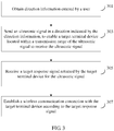
- the present invention provides a method for establishing a wireless communication connection executed by a terminal device, where the method includes: obtaining direction information entered by a user; sending an ultrasonic signal according to a direction indicated by the direction information, to enable a target terminal device located on a transmission path of the ultrasonic signal to receive the ultrasonic signal; receiving a target response signal returned by the target terminal device for the ultrasonic signal; and establishing a wireless communication connection to the target terminal device according to the target response signal.
- the target response signal further includes information about a distance between the target terminal device and an ultrasonic signal transmit end of the terminal device, and the method further includes:
- the receiving a target response signal returned by the target terminal device for the ultrasonic signal includes:
- the sending an ultrasonic signal according to a direction indicated by the direction information includes: adjusting a transmission direction of the ultrasonic signal according to the direction indicated by the direction information, so as to transmit the ultrasonic signal along the direction indicated by the direction information.
- the adjusting a transmission direction of the ultrasonic signal according to the direction information, so as to transmit the ultrasonic signal along the direction indicated by the direction information includes: extending, by an angle of ⁇ , towards each of two sides of the direction by using the direction indicated by the direction information as a center, to form a transmission track of the ultrasonic signal.
- the target response signal includes device information of the target terminal device; and the establishing a wireless communication connection to the target terminal device according to the target response signal includes:
- the target response signal includes a second connection establishment request sent by the target terminal device to the ultrasonic signal transmit end; and the establishing a wireless communication connection to the target terminal device according to the target response signal includes: sending, for the second connection establishment request, a second connection response to the target terminal device, to establish the wireless communication connection to the target terminal device.
- the present invention further provides a terminal device, where the terminal device includes:
- the terminal device further includes a determining unit, where the target response signal further includes information about a distance between the target terminal device and an ultrasonic signal transmit end of the terminal device; the determining unit is configured to determine, according to the distance information about a transmission when the ultrasonic signal is transmitted to the target terminal device, a type of the wireless communication connection established with the target terminal device; and the connection establishment unit is specifically configured to establish the wireless communication connection to the target terminal device according to the target response signal and based on a protocol required by the type of the wireless communication connection.
- the terminal device further includes a identifying unit, where the receiving unit is further configured to receive multiple response signals returned by multiple terminal devices for the ultrasonic signal, where the response signal carries distance information, and the distance information refers to information about a distance between a terminal device that returns the response signal and an ultrasonic signal transmit end; and the identifying unit is configured to identify, from the multiple response signals and according to multiple pieces of distance information carried in the multiple response signals, the target response signal sent by the target terminal device.
- the sending unit is specifically configured to adjust a transmission direction of the ultrasonic signal according to the direction indicated by the direction information and transmit the ultrasonic signal in the direction indicated by the direction information.
- the sending unit is specifically configured to extend, by an angle of ⁇ , towards each of two sides of the direction by using the direction indicated by the direction information as a center, to form a transmission track of the ultrasonic signal.
- the target response signal includes device information of the target terminal device; and the connection establishment unit is specifically configured to send a first connection establishment request to the target terminal device according to the device information, receive a first connection response returned by the target terminal device for the first connection establishment request, and establish the wireless communication connection to the target terminal device according to the first connection response.
- the target response signal includes a second connection establishment request sent by the target terminal device to the ultrasonic signal transmit end; and the connection establishment unit is specifically configured to send, for the second connection establishment request, a second connection response to the target terminal device, to establish the wireless communication connection to the target terminal device.
- the method for establishing a wireless communication connection in embodiments of the present invention, it may be known that direction information entered by a user is obtained, an ultrasonic signal is sent according to a direction indicated by the direction information, a target response signal returned by a target terminal device after receiving the ultrasonic signal is received, and a wireless communication connection to the target terminal device is established according to the response signal. That is, in the embodiments of the present invention, the ultrasonic signal may be sent to the target terminal device that is in the direction indicated by the direction information, as long as the direction information entered by the user is obtained. After the response signal returned by the target terminal device for the ultrasonic signal is received, the wireless communication connection may be established with the target terminal device.
- a party that initiates communication connection establishment does not need to obtain a device identity of the target terminal device, and only needs to obtain information about a direction of the target terminal device relative to the party that initiates communication connection establishment, so as to establish a wireless communication connection to the target terminal device.
- An ultrasonic sensor is a sensor developed by using ultrasonic features.
- An ultrasonic wave is a mechanical wave having a higher vibration frequency higher than an acoustic wave, and has features such as a high frequency, a short wavelength, a small diffraction effect, and especially good directivity, and can be in a ray form for directional propagation.
- the ultrasonic wave has strong directivity.
- FIG. 1a shows a measurement range of an ultrasonic sensor. Referring to FIG. 1a , it may be known that a transmission track of an ultrasonic signal is a fan-shaped beam. A central line of the fan-shaped beam indicates a transmission direction of the ultrasonic signal.
- the ultrasonic signal is scattered around a direction that forms an included angle ⁇ with the transmission direction of the ultrasonic signal, forming a fan-shaped beam.
- ⁇ is in a value range greater than 0° and less than 90°, and a specific value of ⁇ is related to ultrasonic sensor design.
- FIG. 1b is a schematic diagram of an application scenario of a method for establishing a wireless communication connection according to an embodiment of the present invention.
- the application scenario includes a first terminal device and a second terminal device. A direction in which the second terminal device is located relative to the first terminal device is fixed.
- the first terminal device includes an ultrasonic sensor that may be configured to send an ultrasonic signal.
- the second terminal device can receive the ultrasonic signal sent by the first terminal device.
- the first terminal device may send the ultrasonic signal by using the following method: after the direction in which the second terminal device is located relative to the first terminal device is determined, entering information about the direction on the first terminal device, to trigger the ultrasonic sensor located in the first terminal device to send the ultrasonic signal to the second terminal device according to the entered direction information.
- a display screen of the first terminal device is a touchscreen.
- the entering information about the direction on the first terminal device is implemented by means of swiping on the touchscreen.
- the second terminal device After the direction in which the second terminal device is located relative to the first terminal device is determined, swiping on the touchscreen of the first terminal device is performed along the direction in which the second terminal device is located, to trigger the ultrasonic sensor in the first terminal device to transmit the ultrasonic signal along the direction in which the second terminal device is located, so that the first terminal device sends the ultrasonic signal to the second terminal device.
- the second terminal device After receiving the ultrasonic signal, the second terminal device returns a second response signal to the first terminal device for the ultrasonic signal.
- the second response signal carries information used to identify the second terminal device.
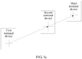
- FIG. 1c is a schematic diagram of another application scenario of a method for establishing a wireless communication connection according to an embodiment of the present invention.
- the application scenario not only includes a first terminal device and a second terminal device, but also includes a third terminal device.
- a direction in which the second terminal device is located relative to the first terminal device is consistent with a direction in which the third terminal device is located relative to the first terminal device.
- the first terminal device sends an ultrasonic signal to the second terminal device
- the ultrasonic signal is also sent to the third terminal device at the same time.
- both the second terminal device and the third terminal device feed back a response signal for the ultrasonic signal.
- the second terminal device feeds back a second response signal to the first terminal device, and the second response signal carries information used to identify the second terminal device.
- the third terminal device feeds back a third response signal to the first terminal device, and the third response signal also carries information used to identify the third terminal device.
- the first terminal device determines, according to the information carried in the second response signal and the information carried in the third response signal, whether a target response signal is the second response signal or the third response signal, and establishes, according to the determined target response signal, a wireless communication connection to a terminal device that feeds back the target response signal.
- the first terminal device determines, according to an identity carried in the second response signal, that the second response signal is the target response signal, the second terminal device is a target terminal device, and the first terminal device establishes a wireless communication connection to the second terminal device.
- FIG. 3a is a schematic flowchart of a method for establishing a wireless communication connection according to an embodiment of the present invention.
- the method for establishing a wireless communication connection in this embodiment may be applied to the application scenario shown in FIG. 1b or FIG. 1c .
- this embodiment of the present invention is executed by a mobile intelligent terminal, and an ultrasonic sensor is disposed inside the mobile intelligent terminal.
- a display screen of the mobile intelligent terminal is a touchscreen.
- the mobile intelligent terminal may be a smartphone, a tablet personal computer (Tablet Personal Computer, Tablet PC), a PAD, or the like.
- FIG. 2 is a logical structure diagram of an operating system of the mobile intelligent terminal according to this embodiment of the present invention.
- the operating system includes a kernel layer, a kernel library layer, an application architecture layer, and an application layer.
- the kernel layer includes various sensor drivers, such as a gyroscope sensor driver, a fingerprint sensor driver, and a heart rate sensor driver, and also includes an ultrasonic sensor driver, where the ultrasonic sensor driver is configured to drive an ultrasonic sensor.
- a hardware structure of the mobile intelligent terminal corresponding to this embodiment of the present invention also includes an ultrasonic sensor that is configured to send an ultrasonic signal. Referring to FIG.
- the kernel library layer of the mobile intelligent terminal when the display screen of the mobile intelligent terminal is a touchscreen, the kernel library layer of the mobile intelligent terminal also includes the touchscreen or a gesture. Further, the application architecture layer of the mobile intelligent terminal includes ultrasonic sensor calling, control, management, and the like. The application layer of the mobile intelligent terminal includes a corresponding application program APP, and during running, the APP needs to use the ultrasonic sensor to send an ultrasonic signal.
- the APP may be a social APP, or may be a data transmission APP.
- this embodiment of the present invention provides the method for establishing a wireless communication connection, where the method includes the following steps.
- S301 Obtain direction information entered by a user.
- S303 Send an ultrasonic signal in a direction indicated by the direction information, to enable a target terminal device located within a transmission range of the ultrasonic signal to receive the ultrasonic signal.
- the sending an ultrasonic signal in a direction indicated by the direction information specifically includes: swiping on the touchscreen of the mobile terminal device along the direction indicated by the direction information.
- the ultrasonic senor located inside the mobile terminal device sends the ultrasonic signal along the swiping direction.
- the ultrasonic signal is generally a beam as shown in FIG. 1a , that is, an angle ⁇ is extended towards each of two sides of the swiping direction by using the swiping direction as a central line to form a transmission track of the ultrasonic signal.
- ⁇ >0°
- a maximum value of ⁇ depends on a maximum offset angle of the ultrasonic sensor.
- the maximum offset angle of the ultrasonic sensor does not exceed 45°, and correspondingly, 0° ⁇ 45°.
- S305 Receive a target response signal returned by the target terminal device for the ultrasonic signal.
- the target terminal device is located within the transmission range of the ultrasonic signal, and therefore, the target terminal device generally can receive the ultrasonic signal. After the target terminal device receives the ultrasonic signal, the target terminal device returns a response signal for the ultrasonic signal, where the response signal is specifically named the target response signal.
- multiple terminal devices are located within the transmission range of the ultrasonic signal (the multiple terminal devices include the target terminal device), and in a general case, all the multiple terminal devices receive the ultrasonic signal, and return response signals respectively for the ultrasonic signal. That is, an entity for executing the present invention may receive multiple response signals, where the multiple response signals include the target response signal. Then, what needs to be done next is to identify the target response signal from the multiple response signals.
- the response signal includes information about a distance between a terminal device that returns the response signal and an ultrasonic signal transmit end. Therefore, the target response signal sent by the target terminal device can be identified according to different distance information carried in each response signal of the multiple response signals.
- S307 Establish a wireless communication connection to the target terminal device according to the target response signal.
- the step includes at least two cases:
- the target response signal includes device information of the target terminal device.
- the establishing a wireless communication connection to the target terminal device according to the target response signal includes: sending a first connection establishment request to the target terminal device according to the device information of the target terminal device, receiving a first connection response returned by the target terminal device for the first connection establishment request, and establishing the wireless communication connection to the target terminal device according to the first connection response.
- the target response signal includes a second connection establishment request sent by the target terminal device to the ultrasonic signal transmit end. That is, when returning the target response signal, the target terminal device sends the second connection establishment request, where the second connection establishment request is included in the target response signal. Therefore, the establishing a wireless communication connection to the target terminal device according to the target response signal includes: sending a second connection response to the target terminal device for the second connection establishment request, to establish the wireless communication connection to the target terminal device.
- the target response signal further includes information about a distance between the target terminal device and the ultrasonic signal transmit end. Therefore, the method provided in this embodiment of the present invention further includes: determining, according to the distance information about a transmission when the ultrasonic signal is transmitted to the target terminal device, a type of the wireless communication connection established with the target terminal device.
- the type of the wireless communication connection includes infrared communication, near field communication NFC, Bluetooth, wireless local area network WLAN, cellular network, and the like.
- the distance between the entity for executing this solution and the target terminal device and the type of the wireless communication connection may have the following relationships: if the distance is in a range of 1 m to 10 m, the corresponding type of the wireless communication connection is infrared communication; if the distance is in a range of 10 m to 50 m, the corresponding type of the wireless communication connection is Bluetooth; if the distance is in a range of 50 m to 100 m, the corresponding type of the wireless communication connection is wireless local area network WLAN; and if the distance exceeds 100 m, the corresponding type of the wireless communication connection is cellular network.
- the establishing a wireless communication connection to the target terminal device according to the target response signal specifically includes: establishing the wireless communication connection to the target terminal device according to the target response signal and based on a protocol required by the type of the wireless communication connection.
- an ultrasonic signal may be sent to a target terminal device as long as position information of the target terminal device is determined, so as to establish a wireless communication connection to the target terminal device.
- no communication information of the target terminal device needs to be obtained to establish the wireless communication connection to the target terminal device. This reduces a time required for establishing the wireless communication connection and improves efficiency of establishing the wireless communication connection.
- the foregoing solution further provides that an appropriate communication type is selected for the wireless communication connection to the target terminal device according to information about a distance to the target terminal device.
- An advantage of this solution lies in that wireless communication resources are utilized appropriately.
- FIG. 4a is a schematic structural diagram of a terminal device 40 according to an embodiment of the present invention.
- the terminal device 40 may execute the method in Embodiment 1, and may be applied to the application scenario shown in FIG. 1b and correspond to the first terminal device shown in FIG. 1b .
- the terminal device 40 may also be applied to the application scenario shown in FIG. 1b , and correspond to the first terminal device shown in FIG. 1c .
- an ultrasonic sensor is disposed inside the terminal device 40.
- a display screen of the terminal device 40 is a touchscreen.
- the terminal device 40 may be a smartphone, a tablet personal computer (Tablet Personal Computer, Tablet PC), a PAD, or the like.
- FIG. 2 A logical structure of an operating system of the terminal device 40 is shown in FIG. 2 .
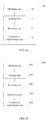
- the terminal device 40 includes an obtaining unit 41, a sending unit 43, a receiving unit 45, and a connection establishment unit 48.
- the obtaining unit 41 is configured to obtain direction information entered by a user.
- the obtaining unit 41 specifically obtains, according to information about user's swiping on the display screen of the terminal device 40 or information about a user's gesture on the display screen of the terminal device 40, the direction information entered by the user.
- the sending unit 43 is configured to send an ultrasonic signal in a direction indicated by the direction information, to enable a target terminal device located within a transmission range of the ultrasonic signal to receive the ultrasonic signal.
- the sending unit 43 is specifically configured to adjust a transmission direction of the ultrasonic signal according to the direction indicated by the direction information and transmit the ultrasonic signal in the direction indicated by the direction information.
- the adjusting, by the sending unit 43, a transmission direction of the ultrasonic signal according to the direction indicated by the direction information refers to extending, by the sending unit 43, by an angle of ⁇ , towards each of two sides of the direction by using the direction indicated by the direction information as a center, to form a transmission track of the ultrasonic signal, where ⁇ >0°.
- the sending unit 43 is specifically an ultrasonic sensor, and therefore a maximum value of ⁇ depends on a maximum offset angle of the ultrasonic sensor. Generally, the maximum offset angle of the ultrasonic sensor does not exceed 45°, and correspondingly, 0° ⁇ 45°.
- the receiving unit 45 is configured to receive a target response signal returned by the target terminal device for the ultrasonic signal.
- the target terminal device is located within the transmission range of the ultrasonic signal, and therefore, the target terminal device generally can receive the ultrasonic signal. After the target terminal device receives the ultrasonic signal, the target terminal device returns a response signal for the ultrasonic signal, where the response signal is specifically named the target response signal.
- a terminal device 400 shown in FIG. 4b refers to a terminal device 400 shown in FIG. 4b .
- a difference between the terminal device 400 and the terminal device 40 lies in that the terminal device 400 further includes a identifying unit 406.
- the multiple terminal devices When multiple terminal devices are located within the transmission range of the ultrasonic signal (the multiple terminal devices include the target terminal device), and in a general case, all the multiple terminal devices receive the ultrasonic signal, and return response signals respectively for the ultrasonic signal. That is, the receiving unit 405 receives multiple response signals, where the multiple response signals include the target response signal. Then, the identifying unit 406 identifies the target response signal from the multiple response signals.
- the response signal includes information about a distance between a terminal device that returns the response signal and an ultrasonic signal transmit end. Therefore, the identifying unit 406 can identify, according to different distance information carried in each response signal of the multiple response signals, the target response signal sent by the target terminal device.
- the connection establishment unit 48 is configured to establish a wireless communication connection to the target terminal device according to the target response signal.
- the connection establishment unit 48 is specifically configured to send a first connection establishment request to the target terminal device according to the device information, receive a first connection response returned by the target terminal device for the first connection establishment request, and establish the wireless communication connection to the target terminal device according to the first connection response.
- the connection establishment unit 48 is specifically configured to send a second connection response to the target terminal device for the second connection establishment request, to establish the wireless communication connection to the target terminal device.
- a terminal device 410 shown in FIG. 4c refers to a terminal device 410 shown in FIG. 4c .
- a difference between the terminal device 410 and the terminal device 40 lies in that the terminal device 410 further includes a determining unit 417.
- the determining unit 417 is configured to determine, according to the distance information about a transmission when the ultrasonic signal is transmitted to the target terminal device, a type of the wireless communication connection established with the target terminal device.
- the connection establishment unit 418 is specifically configured to establish the wireless communication connection to the target terminal device according to the target response signal and based on a protocol required by the type of the wireless communication connection.
- the type of the wireless communication connection includes infrared communication, near field communication NFC, Bluetooth, wireless local area network WLAN, cellular network, and the like.
- the distance between the terminal device 410 and the target terminal device and the type of the wireless communication connection may have the following relationships: if the distance is in a range of 1 m to 10 m, the corresponding type of the wireless communication connection is infrared communication; if the distance is in a range of 10 m to 50 m, the corresponding type of the wireless communication connection is Bluetooth; if the distance is in a range of 50 m to 100 m, the corresponding type of the wireless communication connection is wireless local area network WLAN; and if the distance exceeds 100 m, the corresponding type of the wireless communication connection is cellular network.
- a correspondence between the distance between the terminal device 410 and the target terminal device and the type of the wireless communication connection is set manually, and the foregoing description is exemplary. The correspondence is not limited to the corresponding relationships in the foregoing example.
- the type of the wireless communication connection is not limited to the foregoing listed types, either, and may also include near field communication NFC and the like, which is not limited in the present invention.
- the terminal device 400 shown in FIG. 4b includes the identifying unit 406 additionally; and compared with the terminal device 40 shown in FIG. 4a , the terminal device 410 shown in FIG. 4c includes the determining unit 417 additionally.
- the terminal device 410 shown in FIG. 4c includes the determining unit 417 additionally.
- For a specific function of the identifying unit reference may be made to the embodiment shown in FIG. 4b
- a specific function of the determining unit reference may be made to the embodiment shown in FIG. 4c .
- an ultrasonic signal may be sent to a target terminal device as long as position information of the target terminal device is known, so as to establish a wireless communication connection to the target terminal device.
- the terminal device provided in this embodiment of the present invention does not need to obtain communication information of the target terminal device. This reduces a time required for establishing the wireless communication connection and improves efficiency of establishing the wireless communication connection.
- the present invention further provides that a type of wireless communication with the target terminal device is determined according to information about a distance between the terminal device and the target terminal device.
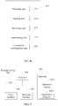
- FIG. 5 is a schematic structural diagram of another terminal device 500 according to an embodiment of the present invention.
- the terminal device 500 may execute the method in Embodiment 1, and may be applied to the application scenario shown in FIG. 1b and correspond to the first terminal device shown in FIG. 1b .
- the terminal device 500 may also be applied to the application scenario shown in FIG. 1b and correspond to the first terminal device shown in FIG. 1c .
- an ultrasonic sensor is disposed inside the terminal device 500.
- a display screen of the terminal device 40 is a touchscreen.
- the terminal device 40 may be a smartphone, a tablet personal computer (Tablet Personal Computer, Tablet PC), a PAD, or the like.
- FIG. 2 A logical structure of an operating system of the terminal device 40 is shown in FIG. 2 .
- the terminal device 500 includes at least one processor 501, at least one network interface 504 or another user interface 503, a memory 505, and at least one communications bus 502.
- the communications bus 502 is configured to implement connection communication between these components.
- the terminal device 500 includes the user interface 503, including a display (for example, a touchscreen, an LCD, a CTR, holographic Imaging (Holographic) or a projector (Projector)), a keyboard, or a click device (for example, a mouse, a trackball (trackball), a touch board, or a touchscreen).
- a display for example, a touchscreen, an LCD, a CTR, holographic Imaging (Holographic) or a projector (Projector)
- a keyboard for example, a mouse, a trackball (trackball), a touch board, or a touchscreen.
- a click device for example, a mouse, a trackball (trackball), a touch board, or a touchscreen.
- the memory 505 may include a read-only memory and a random access memory, and provide an instruction and data for the processor.
- a part of the memory 505 may include a non-volatile random access memory (NVRAM).
- NVRAM non-volatile random access memory
- the memory 505 stores the following elements: an executable module or data structure, or a subset of the executable module or data structure, or an extended set of the executable module or data structure.
- An operating system 5051 includes various system programs, such as a framework layer, a kernel library layer, and a driver layer, and is configured to implement various basic services and process hardware-based tasks.
- An application program module 5052 includes various application programs, such as a launcher (launcher), a media player (Media Player), and a browser (Browser), and is configured to implement various application services.
- launcher launcher
- Media Player media player
- Browser Browser
- the processor 501 is configured to obtain, by calling a program or an instruction stored in the memory 505, direction information entered by a user, and send an ultrasonic signal in a direction indicated by the direction information, to enable a target terminal device located within a transmission range of the ultrasonic signal to receive the ultrasonic signal; and is configured to receive a target response signal returned by the target terminal device for the ultrasonic signal, and establish a wireless communication connection to the target terminal device according to the target response signal.
- the direction information entered by the user is information about a user's swiping direction on the touchscreen or information about a user's gesture on the touchscreen.
- the processor 501 is further configured to receive multiple response signals returned by multiple terminal devices for the ultrasonic signal, where the response signal carries distance information, and the distance information refers to information about a distance between a terminal device that returns the response signal and an ultrasonic signal transmit end; and is configured to identify, from the multiple response signals and according to multiple pieces of distance information carried in the multiple response signals, the target response signal sent by the target terminal device.
- the processor 501 is specifically configured to adjust a transmission direction of the ultrasonic signal according to the direction indicated by the direction information and transmit the ultrasonic signal in the direction indicated by the direction information.
- the processor 501 is specifically configured to extend, by an angle of ⁇ , towards each of two sides of the direction by using the direction indicated by the direction information as a center, to form a transmission track of the ultrasonic signal.
- ⁇ is in a range of 0 to a maximum offset angle of the ultrasonic sensor.
- the maximum offset angle of the ultrasonic sensor does not exceed 45°, and correspondingly, 0° ⁇ 45°.
- the processor 501 is specifically configured to send a first connection establishment request to the target terminal device according to the device information, receive a first connection response returned by the target terminal device for the first connection establishment request, and establish the wireless communication connection to the target terminal device according to the first connection response.
- the processor 501 is specifically configured to send a second connection response to the target terminal device for the second connection establishment request, to establish the wireless communication connection to the target terminal device.
- the processor 501 is specifically configured to determine, according to the distance information about a transmission when the ultrasonic signal is transmitted to the target terminal device, a type of the wireless communication connection established with the target terminal device.
- the type of the wireless communication connection includes infrared communication, near field communication NFC, Bluetooth, wireless local area network WLAN, cellular network, and the like.
- the distance between the terminal device 410 and the target terminal device and the type of the wireless communication connection may have the following relationships: if the distance is in a range of 1 m to 10 m, the corresponding type of the wireless communication connection is infrared communication; if the distance is in a range of 10 m to 50 m, the corresponding type of the wireless communication connection is Bluetooth; if the distance is in a range of 50 m to 100 m, the corresponding type of the wireless communication connection is wireless local area network WLAN; and if the distance exceeds 100 m, the corresponding type of the wireless communication connection is cellular network.
- a correspondence between the distance between the terminal device 410 and the target terminal device and the type of the wireless communication connection is set manually, and the foregoing description is exemplary. The correspondence is not limited to the corresponding relationships in the foregoing example.
- the type of the wireless communication connection is not limited to the foregoing listed types, either, and may also include near field communication NFC and the like, which is not limited in the present invention.
- an ultrasonic signal may be sent to a target terminal device as long as position information of the target terminal device is known, so as to establish a wireless communication connection to the target terminal device.
- the terminal device provided in this embodiment of the present invention does not need to obtain communication information of the target terminal device. This reduces a time required for establishing the wireless communication connection and improves efficiency of establishing the wireless communication connection.
- the present invention further provides that a type of wireless communication with the target terminal device is determined according to information about a distance between the terminal device and the target terminal device.
- the disclosed system, apparatus, and method may be implemented in other manners.
- the described apparatus embodiments are merely exemplary.
- the unit division is merely logical function division and may be other division in actual implementation.
- multiple units or components may be combined or integrated into another system, or some features may be ignored or not performed.
- the displayed or discussed mutual couplings or direct couplings or communication connections may be implemented by using some interfaces.
- the indirect couplings or communication connections between the apparatuses or units may be implemented in electronic, mechanical, or other forms.
- the units described as separate parts may or may not be physically separate, and parts displayed as units may or may not be physical units, may be located in one position, or may be distributed on multiple network units. Some or all of the units may be selected according to actual needs to achieve the objectives of the solutions of the embodiments.
- functional units in the embodiments of the present invention may be integrated into one processing unit, or each of the units may exist alone physically, or two or more units are integrated into one unit.
- the functions When the functions are implemented in a form of a software functional unit and sold or used as an independent product, the functions may be stored in a computer-readable storage medium. Based on such an understanding, the technical solutions of the present invention essentially, or the part contributing to the prior art, or some of the technical solutions may be implemented in a form of a software product.
- the software product is stored in a storage medium, and includes several instructions for instructing a computer device (which may be a personal computer, a server, a network device, or the like) to perform all or some of the steps of the methods described in the embodiments of the present invention.
- the foregoing storage medium includes: any medium that can store program code, such as a USB flash drive, a removable hard disk, a read-only memory (ROM, Read-Only Memory), a random access memory (RAM, Random Access Memory), a magnetic disk, or an optical disc.
- program code such as a USB flash drive, a removable hard disk, a read-only memory (ROM, Read-Only Memory), a random access memory (RAM, Random Access Memory), a magnetic disk, or an optical disc.
Description
- The present invention relates to the field of wireless communications technologies, and in particular, to a method for establishing a wireless communication connection and a terminal device.
- In the prior art, to establish a wireless communication connection to a terminal device B in a specific direction, a terminal device A needs to first obtain identity information of the terminal device B. The identity information is used to identify the terminal device B, and specifically, the identity information includes number information, cell identity information, mobile switching center identity information, location area identity information, and the like that are of the terminal device B. The terminal device A sends a connection establishment request to the terminal device B according to the identity information, so as to establish a communication connection to the terminal device B. A disadvantage of this solution is that, to establish the communication connection to the terminal device B in the specific direction, the terminal device A needs to obtain the identity information of the terminal device B before sending the connection establishment request to the terminal device B, and then sends the connection establishment request to the terminal device B according to the identity information of the terminal device B. The disadvantage of this solution is that a party that initiates a communication connection establishment request needs to obtain identity information of a target terminal device before sending a connection establishment request.
-
US 2009/0265470 A1 discusses a technology by which a gesture made with a source device, such as a throwing or pointing motion, is used to automatically set up a connection with another device to which the gesture is directed. -
US 2010/0278345 A1 discusses a method and apparatus that establish a first communication channel or pair with a target device in proximity to a source device through sending of a pairing message including a secret and an identifier. -
CN 103825661 A discusses a method for establishing a connection relationship, The method comprising the steps of receiving an instruction of connecting the connection relationship of a user; sending a first ultrasonic wave according to the instruction, so as to establish an ultrasonic wave connection relationship with a receiving end which receives the first ultrasonic wave; establishing a second connection relationship with the receiving end by a second communication mode by virtue of the ultrasonic wave connection relationship. - The present invention provides a method for establishing a wireless communication connection and a terminal device. A connection establishment request may be sent to a target terminal device as long as information about a direction of the target terminal device relative to a party sending a communication connection request is obtained. This improves efficiency of sending a connection establishment request by a communication connection establishment initiator.
- According to a first aspect, the present invention provides a method for establishing a wireless communication connection executed by a terminal device, where the method includes: obtaining direction information entered by a user;
sending an ultrasonic signal according to a direction indicated by the direction information, to enable a target terminal device located on a transmission path of the ultrasonic signal to receive the ultrasonic signal;
receiving a target response signal returned by the target terminal device for the ultrasonic signal; and
establishing a wireless communication connection to the target terminal device according to the target response signal. - The target response signal further includes information about a distance between the target terminal device and an ultrasonic signal transmit end of the terminal device, and the method further includes:
- determining, according to the distance information about a transmission when the ultrasonic signal is transmitted to the target terminal device, a type of the wireless communication connection established with the target terminal device; and
- the establishing a wireless communication connection to the target terminal device according to the target response signal includes:
establishing the wireless communication connection to the target terminal device according to the target response signal and based on a protocol required by the type of the wireless communication connection. - With reference to the first aspect, in a first implementation manner of the first aspect, the receiving a target response signal returned by the target terminal device for the ultrasonic signal includes:
- receiving multiple response signals returned by multiple terminal devices for the ultrasonic signal, where the response signal carries distance information, and the distance information refers to information about a distance between a terminal device that returns the response signal and an ultrasonic signal transmit end; and
- identifying, from the multiple response signals and according to multiple pieces of distance information carried in the multiple response signals, the target response signal sent by the target terminal device.
- With reference to the first aspect or the first implementation manner of the first aspect, in a second implementation manner of the first aspect, the sending an ultrasonic signal according to a direction indicated by the direction information includes:
adjusting a transmission direction of the ultrasonic signal according to the direction indicated by the direction information, so as to transmit the ultrasonic signal along the direction indicated by the direction information. - With reference to the second implementation manner of the first aspect, in a third implementation manner of the first aspect, the adjusting a transmission direction of the ultrasonic signal according to the direction information, so as to transmit the ultrasonic signal along the direction indicated by the direction information includes:
extending, by an angle of α, towards each of two sides of the direction by using the direction indicated by the direction information as a center, to form a transmission track of the ultrasonic signal. - With reference to any one of the first aspect, or the first implementation manner of the first aspect to the third implementation manner of the first aspect, in a fourth implementation manner of the first aspect, the target response signal includes device information of the target terminal device; and
the establishing a wireless communication connection to the target terminal device according to the target response signal includes: - sending a first connection establishment request to the target terminal device according to the device information; and
- receiving a first connection response returned by the target terminal device for the first connection establishment request, and establishing the wireless communication connection to the target terminal device according to the first connection response.
- With reference to any one of the first aspect, or the first implementation manner of the first aspect to the third implementation manner of the first aspect, in a fifth implementation manner of the first aspect, the target response signal includes a second connection establishment request sent by the target terminal device to the ultrasonic signal transmit end; and
the establishing a wireless communication connection to the target terminal device according to the target response signal includes:
sending, for the second connection establishment request, a second connection response to the target terminal device, to establish the wireless communication connection to the target terminal device. - According to a second aspect, the present invention further provides a terminal device, where the terminal device includes:
- an obtaining unit, configured to obtain direction information entered by a user;
- a sending unit, configured to send an ultrasonic signal in a direction indicated by the direction information, to enable a target terminal device located within a transmission range of the ultrasonic signal to receive the ultrasonic signal;
- a receiving unit, configured to receive a target response signal returned by the target terminal device for the ultrasonic signal; and
- a connection establishment unit, configured to establish a wireless communication connection to the target terminal device according to the target response signal.
- The terminal device further includes a determining unit, where
the target response signal further includes information about a distance between the target terminal device and an ultrasonic signal transmit end of the terminal device;
the determining unit is configured to determine, according to the distance information about a transmission when the ultrasonic signal is transmitted to the target terminal device, a type of the wireless communication connection established with the target terminal device; and
the connection establishment unit is specifically configured to establish the wireless communication connection to the target terminal device according to the target response signal and based on a protocol required by the type of the wireless communication connection. - With reference to the second aspect, in a first implementation manner of the second aspect, the terminal device further includes a identifying unit, where
the receiving unit is further configured to receive multiple response signals returned by multiple terminal devices for the ultrasonic signal, where the response signal carries distance information, and the distance information refers to information about a distance between a terminal device that returns the response signal and an ultrasonic signal transmit end; and
the identifying unit is configured to identify, from the multiple response signals and according to multiple pieces of distance information carried in the multiple response signals, the target response signal sent by the target terminal device. - With reference to the second aspect or the first implementation manner of the second aspect, in a second implementation manner of the second aspect, the sending unit is specifically configured to adjust a transmission direction of the ultrasonic signal according to the direction indicated by the direction information and transmit the ultrasonic signal in the direction indicated by the direction information.
- With reference to the second aspect or the first implementation manner of the second aspect, in a third implementation manner of the second aspect, the sending unit is specifically configured to extend, by an angle of α, towards each of two sides of the direction by using the direction indicated by the direction information as a center, to form a transmission track of the ultrasonic signal.
- With reference to any one of the second aspect, or the first implementation manner of the second aspect to the third implementation manner of the second aspect, in a fourth implementation manner of the second aspect, the target response signal includes device information of the target terminal device; and
the connection establishment unit is specifically configured to send a first connection establishment request to the target terminal device according to the device information, receive a first connection response returned by the target terminal device for the first connection establishment request, and establish the wireless communication connection to the target terminal device according to the first connection response. - With reference to any one of the second aspect, or the first implementation manner of the second aspect to the third implementation manner of the second aspect, in a fifth implementation manner of the second aspect, the target response signal includes a second connection establishment request sent by the target terminal device to the ultrasonic signal transmit end; and
the connection establishment unit is specifically configured to send, for the second connection establishment request, a second connection response to the target terminal device, to establish the wireless communication connection to the target terminal device. - According to the method for establishing a wireless communication connection in embodiments of the present invention, it may be known that direction information entered by a user is obtained, an ultrasonic signal is sent according to a direction indicated by the direction information, a target response signal returned by a target terminal device after receiving the ultrasonic signal is received, and a wireless communication connection to the target terminal device is established according to the response signal. That is, in the embodiments of the present invention, the ultrasonic signal may be sent to the target terminal device that is in the direction indicated by the direction information, as long as the direction information entered by the user is obtained. After the response signal returned by the target terminal device for the ultrasonic signal is received, the wireless communication connection may be established with the target terminal device. Therefore, in the technical solutions provided in the embodiments of the present invention, to send an ultrasonic signal to a target terminal device, a party that initiates communication connection establishment does not need to obtain a device identity of the target terminal device, and only needs to obtain information about a direction of the target terminal device relative to the party that initiates communication connection establishment, so as to establish a wireless communication connection to the target terminal device.
- To describe the technical solutions in the embodiments of the present invention more clearly, the following briefly describes the accompanying drawings required for describing the embodiments or the prior art. Apparently, the accompanying drawings in the following description show merely some embodiments of the present invention, and a person of ordinary skill in the art may still derive other drawings from these accompanying drawings without creative efforts.
-
FIG. 1a is a schematic diagram of a transmission track of an ultrasonic signal; -
FIG. 1b is a schematic diagram of an application scenario according to an embodiment of the present invention; -
FIG. 1c is a schematic diagram of another application scenario according to an embodiment of the present invention; -
FIG. 2 is a schematic structural diagram of an operating system of a terminal device according to an embodiment of the present invention; -
FIG. 3 is a method flowchart of a method for establishing a wireless communication connection according to an embodiment of the present invention; -
FIG. 4a is a schematic structural diagram of a terminal device according to an embodiment of the present invention; -
FIG. 4b is a schematic structural diagram of another terminal device according to an embodiment of the present invention; -
FIG. 4c is a schematic structural diagram of still another terminal device according to an embodiment of the present invention; and -
FIG. 5 is a structural block diagram of a terminal device according to an embodiment of the present invention. - The following clearly and completely describes the technical solutions in the embodiments of the present invention with reference to the accompanying drawings in the embodiments of the present invention. Apparently, the described embodiments are some but not all of the embodiments of the present invention. All other embodiments obtained by a person of ordinary skill in the art based on the embodiments of the present invention without creative efforts shall fall within the protection scope of the present invention.
- An ultrasonic sensor is a sensor developed by using ultrasonic features. An ultrasonic wave is a mechanical wave having a higher vibration frequency higher than an acoustic wave, and has features such as a high frequency, a short wavelength, a small diffraction effect, and especially good directivity, and can be in a ray form for directional propagation. The ultrasonic wave has strong directivity.
FIG. 1a shows a measurement range of an ultrasonic sensor. Referring toFIG. 1a , it may be known that a transmission track of an ultrasonic signal is a fan-shaped beam. A central line of the fan-shaped beam indicates a transmission direction of the ultrasonic signal. The ultrasonic signal is scattered around a direction that forms an included angle α with the transmission direction of the ultrasonic signal, forming a fan-shaped beam. It should be noted that α is in a value range greater than 0° and less than 90°, and a specific value of α is related to ultrasonic sensor design. - Referring to
FIG. 1b, FIG. 1b is a schematic diagram of an application scenario of a method for establishing a wireless communication connection according to an embodiment of the present invention. The application scenario includes a first terminal device and a second terminal device. A direction in which the second terminal device is located relative to the first terminal device is fixed. In this embodiment of the present invention, the first terminal device includes an ultrasonic sensor that may be configured to send an ultrasonic signal. Correspondingly, the second terminal device can receive the ultrasonic signal sent by the first terminal device. - The first terminal device may send the ultrasonic signal by using the following method: after the direction in which the second terminal device is located relative to the first terminal device is determined, entering information about the direction on the first terminal device, to trigger the ultrasonic sensor located in the first terminal device to send the ultrasonic signal to the second terminal device according to the entered direction information. Preferably, a display screen of the first terminal device is a touchscreen. The entering information about the direction on the first terminal device is implemented by means of swiping on the touchscreen. That is, after the direction in which the second terminal device is located relative to the first terminal device is determined, swiping on the touchscreen of the first terminal device is performed along the direction in which the second terminal device is located, to trigger the ultrasonic sensor in the first terminal device to transmit the ultrasonic signal along the direction in which the second terminal device is located, so that the first terminal device sends the ultrasonic signal to the second terminal device.
- Further, after receiving the ultrasonic signal, the second terminal device returns a second response signal to the first terminal device for the ultrasonic signal. The second response signal carries information used to identify the second terminal device.
- Referring to
FIG. 1c, FIG. 1c is a schematic diagram of another application scenario of a method for establishing a wireless communication connection according to an embodiment of the present invention. The application scenario not only includes a first terminal device and a second terminal device, but also includes a third terminal device. In addition, a direction in which the second terminal device is located relative to the first terminal device is consistent with a direction in which the third terminal device is located relative to the first terminal device. In the application scenario, when the first terminal device sends an ultrasonic signal to the second terminal device, the ultrasonic signal is also sent to the third terminal device at the same time. Correspondingly, both the second terminal device and the third terminal device feed back a response signal for the ultrasonic signal. Specifically, the second terminal device feeds back a second response signal to the first terminal device, and the second response signal carries information used to identify the second terminal device. The third terminal device feeds back a third response signal to the first terminal device, and the third response signal also carries information used to identify the third terminal device. After receiving the second response signal and the third response signal, the first terminal device determines, according to the information carried in the second response signal and the information carried in the third response signal, whether a target response signal is the second response signal or the third response signal, and establishes, according to the determined target response signal, a wireless communication connection to a terminal device that feeds back the target response signal. For example, if the first terminal device determines, according to an identity carried in the second response signal, that the second response signal is the target response signal, the second terminal device is a target terminal device, and the first terminal device establishes a wireless communication connection to the second terminal device. - Referring to
FIG. 3a, FIG. 3a is a schematic flowchart of a method for establishing a wireless communication connection according to an embodiment of the present invention. The method for establishing a wireless communication connection in this embodiment may be applied to the application scenario shown inFIG. 1b orFIG. 1c . In addition, this embodiment of the present invention is executed by a mobile intelligent terminal, and an ultrasonic sensor is disposed inside the mobile intelligent terminal. Preferably, a display screen of the mobile intelligent terminal is a touchscreen. Specifically, the mobile intelligent terminal may be a smartphone, a tablet personal computer (Tablet Personal Computer, Tablet PC), a PAD, or the like. - Referring to
FIG. 2, FIG. 2 is a logical structure diagram of an operating system of the mobile intelligent terminal according to this embodiment of the present invention. The operating system includes a kernel layer, a kernel library layer, an application architecture layer, and an application layer. Features of the operating system of the mobile intelligent terminal corresponding to this embodiment of the present invention lie in that: the kernel layer includes various sensor drivers, such as a gyroscope sensor driver, a fingerprint sensor driver, and a heart rate sensor driver, and also includes an ultrasonic sensor driver, where the ultrasonic sensor driver is configured to drive an ultrasonic sensor. Correspondingly, a hardware structure of the mobile intelligent terminal corresponding to this embodiment of the present invention also includes an ultrasonic sensor that is configured to send an ultrasonic signal. Referring toFIG. 2 , when the display screen of the mobile intelligent terminal is a touchscreen, the kernel library layer of the mobile intelligent terminal also includes the touchscreen or a gesture. Further, the application architecture layer of the mobile intelligent terminal includes ultrasonic sensor calling, control, management, and the like. The application layer of the mobile intelligent terminal includes a corresponding application program APP, and during running, the APP needs to use the ultrasonic sensor to send an ultrasonic signal. The APP may be a social APP, or may be a data transmission APP. - Specifically, this embodiment of the present invention provides the method for establishing a wireless communication connection, where the method includes the following steps.
- S301: Obtain direction information entered by a user.
- S303: Send an ultrasonic signal in a direction indicated by the direction information, to enable a target terminal device located within a transmission range of the ultrasonic signal to receive the ultrasonic signal.
- It should be noted that, if the mobile terminal device that executes the method in this embodiment of the present invention is a touchscreen, the sending an ultrasonic signal in a direction indicated by the direction information specifically includes: swiping on the touchscreen of the mobile terminal device along the direction indicated by the direction information. Correspondingly, the ultrasonic senor located inside the mobile terminal device sends the ultrasonic signal along the swiping direction.
- It should be noted that the ultrasonic signal is generally a beam as shown in
FIG. 1a , that is, an angle α is extended towards each of two sides of the swiping direction by using the swiping direction as a central line to form a transmission track of the ultrasonic signal. α>0°, and a maximum value of α depends on a maximum offset angle of the ultrasonic sensor. Generally, the maximum offset angle of the ultrasonic sensor does not exceed 45°, and correspondingly, 0°<α<45°. - S305: Receive a target response signal returned by the target terminal device for the ultrasonic signal.
- Specifically, the target terminal device is located within the transmission range of the ultrasonic signal, and therefore, the target terminal device generally can receive the ultrasonic signal. After the target terminal device receives the ultrasonic signal, the target terminal device returns a response signal for the ultrasonic signal, where the response signal is specifically named the target response signal.
- In another embodiment of the present invention, multiple terminal devices are located within the transmission range of the ultrasonic signal (the multiple terminal devices include the target terminal device), and in a general case, all the multiple terminal devices receive the ultrasonic signal, and return response signals respectively for the ultrasonic signal. That is, an entity for executing the present invention may receive multiple response signals, where the multiple response signals include the target response signal. Then, what needs to be done next is to identify the target response signal from the multiple response signals.
- It should be noted that, in this embodiment of the present invention, the response signal includes information about a distance between a terminal device that returns the response signal and an ultrasonic signal transmit end. Therefore, the target response signal sent by the target terminal device can be identified according to different distance information carried in each response signal of the multiple response signals.
- S307: Establish a wireless communication connection to the target terminal device according to the target response signal.
- Specifically, the step includes at least two cases:
In a first case, the target response signal includes device information of the target terminal device. In this case, the establishing a wireless communication connection to the target terminal device according to the target response signal includes: sending a first connection establishment request to the target terminal device according to the device information of the target terminal device, receiving a first connection response returned by the target terminal device for the first connection establishment request, and establishing the wireless communication connection to the target terminal device according to the first connection response. - In a second case, the target response signal includes a second connection establishment request sent by the target terminal device to the ultrasonic signal transmit end. That is, when returning the target response signal, the target terminal device sends the second connection establishment request, where the second connection establishment request is included in the target response signal. Therefore, the establishing a wireless communication connection to the target terminal device according to the target response signal includes: sending a second connection response to the target terminal device for the second connection establishment request, to establish the wireless communication connection to the target terminal device.
- Further, in still another embodiment of the present invention, the target response signal further includes information about a distance between the target terminal device and the ultrasonic signal transmit end. Therefore, the method provided in this embodiment of the present invention further includes: determining, according to the distance information about a transmission when the ultrasonic signal is transmitted to the target terminal device, a type of the wireless communication connection established with the target terminal device.
- The type of the wireless communication connection includes infrared communication, near field communication NFC, Bluetooth, wireless local area network WLAN, cellular network, and the like. Exemplarily, the distance between the entity for executing this solution and the target terminal device and the type of the wireless communication connection may have the following relationships: if the distance is in a range of 1 m to 10 m, the corresponding type of the wireless communication connection is infrared communication; if the distance is in a range of 10 m to 50 m, the corresponding type of the wireless communication connection is Bluetooth; if the distance is in a range of 50 m to 100 m, the corresponding type of the wireless communication connection is wireless local area network WLAN; and if the distance exceeds 100 m, the corresponding type of the wireless communication connection is cellular network. It should be known that a correspondence between the distance between the entity for executing this solution and the target terminal device and the type of the wireless communication connection is set manually, and the foregoing description is exemplary. The correspondence is not limited to the corresponding relationships in the foregoing example. In addition, the type of the wireless communication connection is not limited to the foregoing listed types, either, and may also include near field communication NFC and the like, which is not limited in the present invention.
- Correspondingly, the establishing a wireless communication connection to the target terminal device according to the target response signal specifically includes: establishing the wireless communication connection to the target terminal device according to the target response signal and based on a protocol required by the type of the wireless communication connection.
- It may be known that, according to the method for establishing a wireless communication connection in this embodiment of the present invention, an ultrasonic signal may be sent to a target terminal device as long as position information of the target terminal device is determined, so as to establish a wireless communication connection to the target terminal device. Compared with the prior art, in the technical solution provided in this embodiment of the present invention, no communication information of the target terminal device needs to be obtained to establish the wireless communication connection to the target terminal device. This reduces a time required for establishing the wireless communication connection and improves efficiency of establishing the wireless communication connection.
- Further, the foregoing solution further provides that an appropriate communication type is selected for the wireless communication connection to the target terminal device according to information about a distance to the target terminal device. An advantage of this solution lies in that wireless communication resources are utilized appropriately.
- Referring to
FIG. 4a, FIG. 4a is a schematic structural diagram of aterminal device 40 according to an embodiment of the present invention. Theterminal device 40 may execute the method in Embodiment 1, and may be applied to the application scenario shown inFIG. 1b and correspond to the first terminal device shown inFIG. 1b . Certainly, theterminal device 40 may also be applied to the application scenario shown inFIG. 1b , and correspond to the first terminal device shown inFIG. 1c . Specifically, an ultrasonic sensor is disposed inside theterminal device 40. Preferably, a display screen of theterminal device 40 is a touchscreen. Specifically, theterminal device 40 may be a smartphone, a tablet personal computer (Tablet Personal Computer, Tablet PC), a PAD, or the like. A logical structure of an operating system of theterminal device 40 is shown inFIG. 2 . - Specifically, the
terminal device 40 includes an obtainingunit 41, a sendingunit 43, a receivingunit 45, and aconnection establishment unit 48. - The obtaining
unit 41 is configured to obtain direction information entered by a user. - Specifically, when the display screen of the
terminal device 40 is a touchscreen, the obtainingunit 41 specifically obtains, according to information about user's swiping on the display screen of theterminal device 40 or information about a user's gesture on the display screen of theterminal device 40, the direction information entered by the user. - The sending
unit 43 is configured to send an ultrasonic signal in a direction indicated by the direction information, to enable a target terminal device located within a transmission range of the ultrasonic signal to receive the ultrasonic signal. - It should be noted that the sending
unit 43 is specifically configured to adjust a transmission direction of the ultrasonic signal according to the direction indicated by the direction information and transmit the ultrasonic signal in the direction indicated by the direction information. The adjusting, by the sendingunit 43, a transmission direction of the ultrasonic signal according to the direction indicated by the direction information refers to extending, by the sendingunit 43, by an angle of α, towards each of two sides of the direction by using the direction indicated by the direction information as a center, to form a transmission track of the ultrasonic signal, where α>0°. It should be noted that the sendingunit 43 is specifically an ultrasonic sensor, and therefore a maximum value of α depends on a maximum offset angle of the ultrasonic sensor. Generally, the maximum offset angle of the ultrasonic sensor does not exceed 45°, and correspondingly, 0°<α<45°. - The receiving
unit 45 is configured to receive a target response signal returned by the target terminal device for the ultrasonic signal. - Specifically, the target terminal device is located within the transmission range of the ultrasonic signal, and therefore, the target terminal device generally can receive the ultrasonic signal. After the target terminal device receives the ultrasonic signal, the target terminal device returns a response signal for the ultrasonic signal, where the response signal is specifically named the target response signal.
- In another embodiment of the present invention, refer to a
terminal device 400 shown inFIG. 4b . A difference between theterminal device 400 and theterminal device 40 lies in that theterminal device 400 further includes a identifyingunit 406. - When multiple terminal devices are located within the transmission range of the ultrasonic signal (the multiple terminal devices include the target terminal device), and in a general case, all the multiple terminal devices receive the ultrasonic signal, and return response signals respectively for the ultrasonic signal. That is, the receiving
unit 405 receives multiple response signals, where the multiple response signals include the target response signal. Then, the identifyingunit 406 identifies the target response signal from the multiple response signals. - It should be noted that, in this embodiment of the present invention, the response signal includes information about a distance between a terminal device that returns the response signal and an ultrasonic signal transmit end. Therefore, the identifying
unit 406 can identify, according to different distance information carried in each response signal of the multiple response signals, the target response signal sent by the target terminal device. - The
connection establishment unit 48 is configured to establish a wireless communication connection to the target terminal device according to the target response signal. - It should be noted that, in a first case, if the target response signal includes device information of the target terminal device, the
connection establishment unit 48 is specifically configured to send a first connection establishment request to the target terminal device according to the device information, receive a first connection response returned by the target terminal device for the first connection establishment request, and establish the wireless communication connection to the target terminal device according to the first connection response. In a second case, if the target response signal includes a second connection establishment request sent by the target terminal device to the ultrasonic signal transmit end, theconnection establishment unit 48 is specifically configured to send a second connection response to the target terminal device for the second connection establishment request, to establish the wireless communication connection to the target terminal device. - In still another embodiment of the present invention, refer to a
terminal device 410 shown inFIG. 4c . A difference between theterminal device 410 and theterminal device 40 lies in that theterminal device 410 further includes a determiningunit 417. - If the target response signal further includes information about a distance between the target terminal device and the ultrasonic signal transmit end, the determining
unit 417 is configured to determine, according to the distance information about a transmission when the ultrasonic signal is transmitted to the target terminal device, a type of the wireless communication connection established with the target terminal device. Correspondingly, theconnection establishment unit 418 is specifically configured to establish the wireless communication connection to the target terminal device according to the target response signal and based on a protocol required by the type of the wireless communication connection. - The type of the wireless communication connection includes infrared communication, near field communication NFC, Bluetooth, wireless local area network WLAN, cellular network, and the like. Exemplarily, the distance between the
terminal device 410 and the target terminal device and the type of the wireless communication connection may have the following relationships: if the distance is in a range of 1 m to 10 m, the corresponding type of the wireless communication connection is infrared communication; if the distance is in a range of 10 m to 50 m, the corresponding type of the wireless communication connection is Bluetooth; if the distance is in a range of 50 m to 100 m, the corresponding type of the wireless communication connection is wireless local area network WLAN; and if the distance exceeds 100 m, the corresponding type of the wireless communication connection is cellular network. It should be known that a correspondence between the distance between theterminal device 410 and the target terminal device and the type of the wireless communication connection is set manually, and the foregoing description is exemplary. The correspondence is not limited to the corresponding relationships in the foregoing example. In addition, the type of the wireless communication connection is not limited to the foregoing listed types, either, and may also include near field communication NFC and the like, which is not limited in the present invention. - Referring to
FIG. 4a, 4b , and4c , compared with theterminal device 40 shown inFIG. 4a , theterminal device 400 shown inFIG. 4b includes the identifyingunit 406 additionally; and compared with theterminal device 40 shown inFIG. 4a , theterminal device 410 shown inFIG. 4c includes the determiningunit 417 additionally. It should be understood that there may be a terminal device that not only includes all function units shown in theterminal device 40, but also includes the identifying unit inFIG. 4b and the determining unit shown inFIG. 4c . For a specific function of the identifying unit, reference may be made to the embodiment shown inFIG. 4b , and for a specific function of the determining unit, reference may be made to the embodiment shown inFIG. 4c . - It may be known that, according to the terminal device provided in this embodiment of the present invention, an ultrasonic signal may be sent to a target terminal device as long as position information of the target terminal device is known, so as to establish a wireless communication connection to the target terminal device. Compared with the prior art, when establishing the wireless communication connection to the target terminal device, the terminal device provided in this embodiment of the present invention does not need to obtain communication information of the target terminal device. This reduces a time required for establishing the wireless communication connection and improves efficiency of establishing the wireless communication connection.
- Further, the present invention further provides that a type of wireless communication with the target terminal device is determined according to information about a distance between the terminal device and the target terminal device. An advantage of this solution lies in that wireless communication resources may be utilized appropriately.
- Referring to
FIG. 5, FIG. 5 is a schematic structural diagram of anotherterminal device 500 according to an embodiment of the present invention. Theterminal device 500 may execute the method in Embodiment 1, and may be applied to the application scenario shown inFIG. 1b and correspond to the first terminal device shown inFIG. 1b . Certainly, theterminal device 500 may also be applied to the application scenario shown inFIG. 1b and correspond to the first terminal device shown inFIG. 1c . Specifically, an ultrasonic sensor is disposed inside theterminal device 500. Preferably, a display screen of theterminal device 40 is a touchscreen. Specifically, theterminal device 40 may be a smartphone, a tablet personal computer (Tablet Personal Computer, Tablet PC), a PAD, or the like. A logical structure of an operating system of theterminal device 40 is shown inFIG. 2 . - Specifically, as shown in
FIG. 5 , theterminal device 500 includes at least oneprocessor 501, at least onenetwork interface 504 or anotheruser interface 503, amemory 505, and at least onecommunications bus 502. Thecommunications bus 502 is configured to implement connection communication between these components. Optionally, theterminal device 500 includes theuser interface 503, including a display (for example, a touchscreen, an LCD, a CTR, holographic Imaging (Holographic) or a projector (Projector)), a keyboard, or a click device (for example, a mouse, a trackball (trackball), a touch board, or a touchscreen). - The
memory 505 may include a read-only memory and a random access memory, and provide an instruction and data for the processor. A part of thememory 505 may include a non-volatile random access memory (NVRAM). - In some embodiments, the
memory 505 stores the following elements: an executable module or data structure, or a subset of the executable module or data structure, or an extended set of the executable module or data structure. - An
operating system 5051 includes various system programs, such as a framework layer, a kernel library layer, and a driver layer, and is configured to implement various basic services and process hardware-based tasks. - An
application program module 5052 includes various application programs, such as a launcher (launcher), a media player (Media Player), and a browser (Browser), and is configured to implement various application services. - In this embodiment of the present invention, the
processor 501 is configured to obtain, by calling a program or an instruction stored in thememory 505, direction information entered by a user, and send an ultrasonic signal in a direction indicated by the direction information, to enable a target terminal device located within a transmission range of the ultrasonic signal to receive the ultrasonic signal; and is configured to receive a target response signal returned by the target terminal device for the ultrasonic signal, and establish a wireless communication connection to the target terminal device according to the target response signal. - It should be noted that when the display screen of the
terminal device 500 is a touchscreen, the direction information entered by the user is information about a user's swiping direction on the touchscreen or information about a user's gesture on the touchscreen. - In another embodiment of the present invention, the
processor 501 is further configured to receive multiple response signals returned by multiple terminal devices for the ultrasonic signal, where the response signal carries distance information, and the distance information refers to information about a distance between a terminal device that returns the response signal and an ultrasonic signal transmit end; and
is configured to identify, from the multiple response signals and according to multiple pieces of distance information carried in the multiple response signals, the target response signal sent by the target terminal device. - It should be noted that the
processor 501 is specifically configured to adjust a transmission direction of the ultrasonic signal according to the direction indicated by the direction information and transmit the ultrasonic signal in the direction indicated by the direction information. - Further, the
processor 501 is specifically configured to extend, by an angle of α, towards each of two sides of the direction by using the direction indicated by the direction information as a center, to form a transmission track of the ultrasonic signal. - It should be noted that the ultrasonic sensor sends the ultrasonic signal. Therefore, a value of α is in a range of 0 to a maximum offset angle of the ultrasonic sensor. Generally, the maximum offset angle of the ultrasonic sensor does not exceed 45°, and correspondingly, 0°<α<45°.
- In still another embodiment of the present invention, if the target response signal includes device information of the target terminal device, the
processor 501 is specifically configured to send a first connection establishment request to the target terminal device according to the device information, receive a first connection response returned by the target terminal device for the first connection establishment request, and establish the wireless communication connection to the target terminal device according to the first connection response. - In still another embodiment of the present invention, if the target response signal includes a second connection establishment request sent by the target terminal device to the ultrasonic signal transmit end, the
processor 501 is specifically configured to send a second connection response to the target terminal device for the second connection establishment request, to establish the wireless communication connection to the target terminal device. - Further, if the target response signal further includes information about a distance between the target terminal device and the ultrasonic signal transmit end, the
processor 501 is specifically configured to determine, according to the distance information about a transmission when the ultrasonic signal is transmitted to the target terminal device, a type of the wireless communication connection established with the target terminal device. The type of the wireless communication connection includes infrared communication, near field communication NFC, Bluetooth, wireless local area network WLAN, cellular network, and the like. Exemplarily, the distance between theterminal device 410 and the target terminal device and the type of the wireless communication connection may have the following relationships: if the distance is in a range of 1 m to 10 m, the corresponding type of the wireless communication connection is infrared communication; if the distance is in a range of 10 m to 50 m, the corresponding type of the wireless communication connection is Bluetooth; if the distance is in a range of 50 m to 100 m, the corresponding type of the wireless communication connection is wireless local area network WLAN; and if the distance exceeds 100 m, the corresponding type of the wireless communication connection is cellular network. It should be known that a correspondence between the distance between theterminal device 410 and the target terminal device and the type of the wireless communication connection is set manually, and the foregoing description is exemplary. The correspondence is not limited to the corresponding relationships in the foregoing example. In addition, the type of the wireless communication connection is not limited to the foregoing listed types, either, and may also include near field communication NFC and the like, which is not limited in the present invention. - It may be known that, according to the terminal device provided in this embodiment of the present invention, an ultrasonic signal may be sent to a target terminal device as long as position information of the target terminal device is known, so as to establish a wireless communication connection to the target terminal device. Compared with the prior art, when establishing the wireless communication connection to the target terminal device, the terminal device provided in this embodiment of the present invention does not need to obtain communication information of the target terminal device. This reduces a time required for establishing the wireless communication connection and improves efficiency of establishing the wireless communication connection.
- Further, the present invention further provides that a type of wireless communication with the target terminal device is determined according to information about a distance between the terminal device and the target terminal device. An advantage of this solution lies in that wireless communication resources may be utilized appropriately.
- Mutual reference may be made among the foregoing embodiments.
- A person of ordinary skill in the art may be aware that, in combination with the examples described in the embodiments disclosed in this specification, units and algorithm steps may be implemented by electronic hardware or a combination of computer software and electronic hardware. Whether the functions are performed by hardware or software depends on particular applications and design constraint conditions of the technical solutions. A person skilled in the art may use different methods to implement the described functions for each particular application, but it should not be considered that the implementation goes beyond the scope of the present invention.
- It may be clearly understood by a person skilled in the art that, for the purpose of convenient and brief description, for a detailed working process of the foregoing system, apparatus, and unit, reference may be made to a corresponding process in the foregoing method embodiments, and details are not described herein.
- In the several embodiments provided in this application, it should be understood that the disclosed system, apparatus, and method may be implemented in other manners. For example, the described apparatus embodiments are merely exemplary. For example, the unit division is merely logical function division and may be other division in actual implementation. For example, multiple units or components may be combined or integrated into another system, or some features may be ignored or not performed. In addition, the displayed or discussed mutual couplings or direct couplings or communication connections may be implemented by using some interfaces. The indirect couplings or communication connections between the apparatuses or units may be implemented in electronic, mechanical, or other forms.
- The units described as separate parts may or may not be physically separate, and parts displayed as units may or may not be physical units, may be located in one position, or may be distributed on multiple network units. Some or all of the units may be selected according to actual needs to achieve the objectives of the solutions of the embodiments.
- In addition, functional units in the embodiments of the present invention may be integrated into one processing unit, or each of the units may exist alone physically, or two or more units are integrated into one unit.
- When the functions are implemented in a form of a software functional unit and sold or used as an independent product, the functions may be stored in a computer-readable storage medium. Based on such an understanding, the technical solutions of the present invention essentially, or the part contributing to the prior art, or some of the technical solutions may be implemented in a form of a software product. The software product is stored in a storage medium, and includes several instructions for instructing a computer device (which may be a personal computer, a server, a network device, or the like) to perform all or some of the steps of the methods described in the embodiments of the present invention. The foregoing storage medium includes: any medium that can store program code, such as a USB flash drive, a removable hard disk, a read-only memory (ROM, Read-Only Memory), a random access memory (RAM, Random Access Memory), a magnetic disk, or an optical disc.
- The foregoing descriptions are merely specific implementation manners of the present invention, but are not intended to limit the protection scope of the present invention. Any variation or replacement readily figured out by a person skilled in the art within the technical scope disclosed in the present invention shall fall within the protection scope of the present invention. Therefore, the protection scope of the present invention shall be subject to the protection scope of the claims.
Claims (12)
- A method for establishing a wireless communication connection executed by a terminal device, comprising:obtaining direction information entered by a user (Step 301);sending an ultrasonic signal in a direction indicated by the direction information, to enable a target terminal device located within a transmission range of the ultrasonic signal to receive the ultrasonic signal (Step 303);receiving a target response signal returned by the target terminal device for the ultrasonic signal (Step 305); andestablishing a wireless communication connection to the target terminal device according to the target response signal (Step 307);characterized in thatthe target response signal further comprises information about a distance between the target terminal device and an ultrasonic signal transmit end of the terminal device, and the method further comprises:determining, according to the distance information when the ultrasonic signal is transmitted to the target terminal device, a type of the wireless communication connection established with the target terminal device; andthe establishing a wireless communication connection to the target terminal device according to the target response signal comprises:
establishing the wireless communication connection to the target terminal device according to the target response signal and based on a protocol required by the type of the wireless communication connection. - The method according to claim 1, wherein the receiving a target response signal returned by the target terminal device for the ultrasonic signal comprises:receiving multiple response signals returned by multiple terminal devices for the ultrasonic signal, wherein the response signal carries distance information, and the distance information refers to information about a distance between a terminal device that returns the response signal and an ultrasonic signal transmit end; andidentifying, from the multiple response signals and according to multiple pieces of distance information carried in the multiple response signals, the target response signal sent by the target terminal device.
- The method according to claim 1 or 2, wherein the sending an ultrasonic signal in a direction indicated by the direction information comprises:
adjusting a transmission direction of the ultrasonic signal according to the direction indicated by the direction information, so as to transmit the ultrasonic signal along the direction indicated by the direction information. - The method according to claim 3, wherein
the adjusting a transmission direction of the ultrasonic signal according to the direction indicated by the direction information, so as to transmit the ultrasonic signal along the direction indicated by the direction information comprises:
extending, by an angle of α, towards each of two sides of the direction by using the direction indicated by the direction information as a central line, to form a transmission track of the ultrasonic signal. - The method according to any one of claims 1 to 4, wherein
the target response signal comprises device information of the target terminal device; and
the establishing a wireless communication connection to the target terminal device according to the target response signal comprises:sending a first connection establishment request to the target terminal device according to the device information; andreceiving a first connection response returned by the target terminal device for the first connection establishment request, and establishing the wireless communication connection to the target terminal device according to the first connection response. - The method according to any one of claims 1 to 4, wherein
the target response signal comprises a second connection establishment request sent by the target terminal device to the ultrasonic signal transmit end; and
the establishing a wireless communication connection to the target terminal device according to the target response signal comprises:
sending, for the second connection establishment request, a second connection response to the target terminal device, to establish the wireless communication connection to the target terminal device. - A terminal device (40; 400; 410)), comprising:an obtaining unit (41; 401; 411), configured to obtain direction information entered by a user;a sending unit (43; 403; 413), configured to send an ultrasonic signal in a direction indicated by the direction information, to enable a target terminal device located within a transmission range of the ultrasonic signal to receive the ultrasonic signal;a receiving unit (45; 405; 415), configured to receive a target response signal returned by the target terminal device for the ultrasonic signal; anda connection establishment unit (48; 408; 418), configured to establish a wireless communication connection to the target terminal device according to the target response signal;characterized in that the terminal device further comprises a determining unit (417) and whereinthe target response signal further comprises information about a distance between the target terminal device and an ultrasonic signal transmit end of the terminal device;the determining unit (417) is configured to determine, according to the distance information when the ultrasonic signal is transmitted to the target terminal device, a type of the wireless communication connection established with the target terminal device; andthe connection establishment unit (48; 408; 418) is specifically configured to establish the wireless communication connection to the target terminal device according to the target response signal and based on a protocol required by the type of the wireless communication connection.
- The terminal device according to claim 7, further comprising a identifying unit (406), wherein
the receiving unit (45; 405; 415) is further configured to receive multiple response signals returned by multiple terminal devices for the ultrasonic signal, wherein the response signal carries distance information, and the distance information refers to information about a distance between a terminal device that returns the response signal and an ultrasonic signal transmit end; and
the identifying unit (406) is configured to identify, from the multiple response signals and according to multiple pieces of distance information carried in the multiple response signals, the target response signal sent by the target terminal device. - The terminal device according to claim 7 or 8, wherein
the sending unit (43; 403; 413) is specifically configured to adjust a transmission direction of the ultrasonic signal according to the direction indicated by the direction information and transmit the ultrasonic signal in the direction indicated by the direction information. - The terminal device according to claim 7 or 8, wherein
the sending unit (43; 403; 413) is specifically configured to extend, by an angle of α, towards each of two sides of the direction by using the direction indicated by the direction information as a central line, to form a transmission track of the ultrasonic signal. - The terminal device according to any one of claims 7 to 10, wherein
the target response signal comprises device information of the target terminal device; and
the connection establishment unit (48; 408; 418) is specifically configured to send a first connection establishment request to the target terminal device according to the device information, receive a first connection response returned by the target terminal device for the first connection establishment request, and establish the wireless communication connection to the target terminal device according to the first connection response. - The terminal device according to any one of claims 7 to 10, wherein
the target response signal comprises a second connection establishment request sent by the target terminal device to the ultrasonic signal transmit end; and
the connection establishment unit (48; 408; 418) is specifically configured to send, for the second connection establishment request, a second connection response to the target terminal device, to establish the wireless communication connection to the target terminal device.
Applications Claiming Priority (2)
| Application Number | Priority Date | Filing Date | Title |
|---|---|---|---|
| CN201410460476.3A CN105472768B (en) | 2014-09-10 | 2014-09-10 | Wirelessly communicate establishment of connection method and terminal device |
| PCT/CN2015/089257 WO2016037569A1 (en) | 2014-09-10 | 2015-09-09 | Wireless communication connection establishing method and terminal device |
Publications (3)
| Publication Number | Publication Date |
|---|---|
| EP3154239A1 EP3154239A1 (en) | 2017-04-12 |
| EP3154239A4 EP3154239A4 (en) | 2017-07-19 |
| EP3154239B1 true EP3154239B1 (en) | 2020-02-05 |
Family
ID=55458354
Family Applications (1)
| Application Number | Title | Priority Date | Filing Date |
|---|---|---|---|
| EP15839187.0A Active EP3154239B1 (en) | 2014-09-10 | 2015-09-09 | Wireless communication connection establishing method and terminal device |
Country Status (4)
| Country | Link |
|---|---|
| US (1) | US9955517B2 (en) |
| EP (1) | EP3154239B1 (en) |
| CN (1) | CN105472768B (en) |
| WO (1) | WO2016037569A1 (en) |
Families Citing this family (4)
| Publication number | Priority date | Publication date | Assignee | Title |
|---|---|---|---|---|
| CN106375840A (en) * | 2016-09-30 | 2017-02-01 | 努比亚技术有限公司 | Screen projection device, mobile terminal and screen projection connection method |
| CN106789461A (en) * | 2016-12-12 | 2017-05-31 | 北京小米移动软件有限公司 | The method and device of intelligent home device connection |
| CN113242349B (en) * | 2020-01-22 | 2022-08-26 | 华为技术有限公司 | Data transmission method, electronic equipment and storage medium |
| CN111542128B (en) * | 2020-04-14 | 2022-02-18 | 支付宝(杭州)信息技术有限公司 | UWB-based equipment interaction method, device and equipment |
Family Cites Families (21)
| Publication number | Priority date | Publication date | Assignee | Title |
|---|---|---|---|---|
| US7031875B2 (en) * | 2001-01-24 | 2006-04-18 | Geo Vector Corporation | Pointing systems for addressing objects |
| US20060259574A1 (en) * | 2005-05-13 | 2006-11-16 | Outland Research, Llc | Method and apparatus for accessing spatially associated information |
| US20070273583A1 (en) * | 2005-09-17 | 2007-11-29 | Outland Research, Llc | Pointing interface for person-to-person interaction through ad-hoc networks |
| US20080051033A1 (en) * | 2006-08-28 | 2008-02-28 | Charles Martin Hymes | Wireless communications with visually- identified targets |
| US20080259731A1 (en) * | 2007-04-17 | 2008-10-23 | Happonen Aki P | Methods and apparatuses for user controlled beamforming |
| US20090140986A1 (en) * | 2007-11-30 | 2009-06-04 | Nokia Corporation | Method, apparatus and computer program product for transferring files between devices via drag and drop |
| US7991896B2 (en) * | 2008-04-21 | 2011-08-02 | Microsoft Corporation | Gesturing to select and configure device communication |
| US7529542B1 (en) * | 2008-04-21 | 2009-05-05 | International Business Machines Corporation | Method of establishing communication between two or more real world entities and apparatuses performing the same |
| WO2010122791A1 (en) * | 2009-04-24 | 2010-10-28 | パナソニック株式会社 | Wireless ultrasonic diagnostic device, wireless ultrasonic probe, and probe certification method |
| US20100278345A1 (en) * | 2009-05-04 | 2010-11-04 | Thomas Matthieu Alsina | Method and apparatus for proximity based pairing of mobile devices |
| US8447070B1 (en) * | 2010-04-19 | 2013-05-21 | Amazon Technologies, Inc. | Approaches for device location and communication |
| CN102624428B (en) * | 2011-01-28 | 2015-01-21 | 国民技术股份有限公司 | System and method for selecting a communication object |
| US8451344B1 (en) * | 2011-03-24 | 2013-05-28 | Amazon Technologies, Inc. | Electronic devices with side viewing capability |
| KR101797627B1 (en) * | 2011-08-10 | 2017-11-15 | 엘지전자 주식회사 | Mobile terminal and control method therof |
| US9302594B2 (en) * | 2012-07-31 | 2016-04-05 | Qualcomm Incorporated | Selective communication based on distance from a plurality of electric vehicle wireless charging stations in a facility |
| JP6271960B2 (en) * | 2012-11-26 | 2018-01-31 | キヤノン株式会社 | Information processing system |
| CN103365597B (en) * | 2013-07-07 | 2016-04-27 | 广州市沃希信息科技有限公司 | Electronic equipment communication method, electronic equipment and electronic equipment communications system |
| US9505314B2 (en) * | 2013-08-09 | 2016-11-29 | Qualcomm Incorporated | Systems, methods, and apparatus related to detecting and identifying electric vehicle and charging station |
| US20150126118A1 (en) * | 2013-11-07 | 2015-05-07 | Peisen Lin | Method and apparatus for intention based contactless device pairing |
| CN103825661B (en) * | 2014-03-13 | 2016-03-02 | 魅族科技(中国)有限公司 | A kind of method that annexation is set up and terminal |
| KR102140753B1 (en) * | 2014-07-14 | 2020-08-03 | 삼성전자주식회사 | Method and apparatus for beamforming in wireless device |
-
2014
- 2014-09-10 CN CN201410460476.3A patent/CN105472768B/en active Active
-
2015
- 2015-09-09 EP EP15839187.0A patent/EP3154239B1/en active Active
- 2015-09-09 WO PCT/CN2015/089257 patent/WO2016037569A1/en active Application Filing
-
2017
- 2017-01-06 US US15/399,861 patent/US9955517B2/en active Active
Also Published As
| Publication number | Publication date |
|---|---|
| WO2016037569A1 (en) | 2016-03-17 |
| US9955517B2 (en) | 2018-04-24 |
| EP3154239A1 (en) | 2017-04-12 |
| EP3154239A4 (en) | 2017-07-19 |
| CN105472768A (en) | 2016-04-06 |
| US20170118785A1 (en) | 2017-04-27 |
| CN105472768B (en) | 2019-10-01 |
Similar Documents
| Publication | Publication Date | Title |
|---|---|---|
| US9955517B2 (en) | Method for establishing wireless communication connection and terminal device | |
| EP3531290B1 (en) | Data backup method, apparatus, electronic device, storage medium, and system | |
| EP2948788B1 (en) | Polled time-of-flight response | |
| US20190095887A1 (en) | Resource transferring method and apparatus | |
| EP3402185B1 (en) | Method and apparatus for transmitting video during voice call | |
| EP2838309B1 (en) | Method, device and system for establishing data connection | |
| US20160291141A1 (en) | Apparatus and method for measuring distance and location | |
| US10579117B2 (en) | Method and apparatus for securing communication of instructions to manage antenna power output | |
| EP3278135B1 (en) | Apparatus and method for measuring distance and location | |
| KR20170041484A (en) | Adaptive communication method and apparatus | |
| WO2022078331A1 (en) | Signal transmitting and signal receiving method, terminal, and communication device | |
| WO2017045283A1 (en) | Method and device for controlling screen between terminals, and storage medium | |
| US10046235B2 (en) | Enhanced peer-to-peer networking exchange | |
| JP2016531479A (en) | Wireless connection switching method, wireless terminal, and system thereof | |
| US10523349B2 (en) | Method for processing concurrent services and terminal | |
| WO2023246757A1 (en) | Computing power service method and apparatus, and terminal | |
| CN110399135B (en) | Method and device for installing application program | |
| CN114428574B (en) | Operation control method, device, storage medium and electronic equipment | |
| WO2016095449A1 (en) | Virtual desktop display method, terminal and storage medium | |
| JP2007219961A (en) | Resource sharing system and resource sharing method | |
| WO2022068705A1 (en) | Method, device, and system for adjusting location information | |
| CN105027082A (en) | On demand ultrasound performance | |
| US10698520B2 (en) | Force touch-based communication enhancement method and terminal | |
| KR101288942B1 (en) | Method for transmitting and receiving of file using near communication and wireless internet, communication terminal therefor | |
| US11737023B2 (en) | Information handling system and peripheral wireless pairing by device positioning and adaptive power control |
Legal Events
| Date | Code | Title | Description |
|---|---|---|---|
| STAA | Information on the status of an ep patent application or granted ep patent |
Free format text: STATUS: THE INTERNATIONAL PUBLICATION HAS BEEN MADE |
|
| PUAI | Public reference made under article 153(3) epc to a published international application that has entered the european phase |
Free format text: ORIGINAL CODE: 0009012 |
|
| STAA | Information on the status of an ep patent application or granted ep patent |
Free format text: STATUS: REQUEST FOR EXAMINATION WAS MADE |
|
| 17P | Request for examination filed |
Effective date: 20170106 |
|
| AK | Designated contracting states |
Kind code of ref document: A1 Designated state(s): AL AT BE BG CH CY CZ DE DK EE ES FI FR GB GR HR HU IE IS IT LI LT LU LV MC MK MT NL NO PL PT RO RS SE SI SK SM TR |
|
| AX | Request for extension of the european patent |
Extension state: BA ME |
|
| A4 | Supplementary search report drawn up and despatched |
Effective date: 20170616 |
|
| RIC1 | Information provided on ipc code assigned before grant |
Ipc: G01S 11/14 20060101ALI20170609BHEP Ipc: H04W 76/02 20090101ALI20170609BHEP Ipc: H04W 8/00 20090101ALI20170609BHEP Ipc: H04W 4/02 20090101ALI20170609BHEP Ipc: H04W 4/00 20090101AFI20170609BHEP |
|
| DAV | Request for validation of the european patent (deleted) | ||
| DAX | Request for extension of the european patent (deleted) | ||
| REG | Reference to a national code |
Ref country code: DE Ref legal event code: R079 Ref document number: 602015046523 Country of ref document: DE Free format text: PREVIOUS MAIN CLASS: H04L0029080000 Ipc: H04W0004020000 |
|
| GRAP | Despatch of communication of intention to grant a patent |
Free format text: ORIGINAL CODE: EPIDOSNIGR1 |
|
| STAA | Information on the status of an ep patent application or granted ep patent |
Free format text: STATUS: GRANT OF PATENT IS INTENDED |
|
| RIC1 | Information provided on ipc code assigned before grant |
Ipc: H04W 4/02 20180101AFI20190819BHEP Ipc: H04W 4/50 20180101ALI20190819BHEP |
|
| INTG | Intention to grant announced |
Effective date: 20190916 |
|
| GRAS | Grant fee paid |
Free format text: ORIGINAL CODE: EPIDOSNIGR3 |
|
| GRAA | (expected) grant |
Free format text: ORIGINAL CODE: 0009210 |
|
| STAA | Information on the status of an ep patent application or granted ep patent |
Free format text: STATUS: THE PATENT HAS BEEN GRANTED |
|
| AK | Designated contracting states |
Kind code of ref document: B1 Designated state(s): AL AT BE BG CH CY CZ DE DK EE ES FI FR GB GR HR HU IE IS IT LI LT LU LV MC MK MT NL NO PL PT RO RS SE SI SK SM TR |
|
| REG | Reference to a national code |
Ref country code: GB Ref legal event code: FG4D |
|
| REG | Reference to a national code |
Ref country code: AT Ref legal event code: REF Ref document number: 1230763 Country of ref document: AT Kind code of ref document: T Effective date: 20200215 |
|
| REG | Reference to a national code |
Ref country code: DE Ref legal event code: R096 Ref document number: 602015046523 Country of ref document: DE |
|
| REG | Reference to a national code |
Ref country code: IE Ref legal event code: FG4D |
|
| REG | Reference to a national code |
Ref country code: CH Ref legal event code: EP |
|
| REG | Reference to a national code |
Ref country code: NL Ref legal event code: MP Effective date: 20200205 |
|
| PG25 | Lapsed in a contracting state [announced via postgrant information from national office to epo] |
Ref country code: PT Free format text: LAPSE BECAUSE OF FAILURE TO SUBMIT A TRANSLATION OF THE DESCRIPTION OR TO PAY THE FEE WITHIN THE PRESCRIBED TIME-LIMIT Effective date: 20200628 Ref country code: FI Free format text: LAPSE BECAUSE OF FAILURE TO SUBMIT A TRANSLATION OF THE DESCRIPTION OR TO PAY THE FEE WITHIN THE PRESCRIBED TIME-LIMIT Effective date: 20200205 Ref country code: RS Free format text: LAPSE BECAUSE OF FAILURE TO SUBMIT A TRANSLATION OF THE DESCRIPTION OR TO PAY THE FEE WITHIN THE PRESCRIBED TIME-LIMIT Effective date: 20200205 Ref country code: NO Free format text: LAPSE BECAUSE OF FAILURE TO SUBMIT A TRANSLATION OF THE DESCRIPTION OR TO PAY THE FEE WITHIN THE PRESCRIBED TIME-LIMIT Effective date: 20200505 |
|
| REG | Reference to a national code |
Ref country code: LT Ref legal event code: MG4D |
|
| PG25 | Lapsed in a contracting state [announced via postgrant information from national office to epo] |
Ref country code: GR Free format text: LAPSE BECAUSE OF FAILURE TO SUBMIT A TRANSLATION OF THE DESCRIPTION OR TO PAY THE FEE WITHIN THE PRESCRIBED TIME-LIMIT Effective date: 20200506 Ref country code: BG Free format text: LAPSE BECAUSE OF FAILURE TO SUBMIT A TRANSLATION OF THE DESCRIPTION OR TO PAY THE FEE WITHIN THE PRESCRIBED TIME-LIMIT Effective date: 20200505 Ref country code: HR Free format text: LAPSE BECAUSE OF FAILURE TO SUBMIT A TRANSLATION OF THE DESCRIPTION OR TO PAY THE FEE WITHIN THE PRESCRIBED TIME-LIMIT Effective date: 20200205 Ref country code: LV Free format text: LAPSE BECAUSE OF FAILURE TO SUBMIT A TRANSLATION OF THE DESCRIPTION OR TO PAY THE FEE WITHIN THE PRESCRIBED TIME-LIMIT Effective date: 20200205 Ref country code: SE Free format text: LAPSE BECAUSE OF FAILURE TO SUBMIT A TRANSLATION OF THE DESCRIPTION OR TO PAY THE FEE WITHIN THE PRESCRIBED TIME-LIMIT Effective date: 20200205 Ref country code: IS Free format text: LAPSE BECAUSE OF FAILURE TO SUBMIT A TRANSLATION OF THE DESCRIPTION OR TO PAY THE FEE WITHIN THE PRESCRIBED TIME-LIMIT Effective date: 20200605 |
|
| PG25 | Lapsed in a contracting state [announced via postgrant information from national office to epo] |
Ref country code: NL Free format text: LAPSE BECAUSE OF FAILURE TO SUBMIT A TRANSLATION OF THE DESCRIPTION OR TO PAY THE FEE WITHIN THE PRESCRIBED TIME-LIMIT Effective date: 20200205 |
|
| PG25 | Lapsed in a contracting state [announced via postgrant information from national office to epo] |
Ref country code: LT Free format text: LAPSE BECAUSE OF FAILURE TO SUBMIT A TRANSLATION OF THE DESCRIPTION OR TO PAY THE FEE WITHIN THE PRESCRIBED TIME-LIMIT Effective date: 20200205 Ref country code: SK Free format text: LAPSE BECAUSE OF FAILURE TO SUBMIT A TRANSLATION OF THE DESCRIPTION OR TO PAY THE FEE WITHIN THE PRESCRIBED TIME-LIMIT Effective date: 20200205 Ref country code: RO Free format text: LAPSE BECAUSE OF FAILURE TO SUBMIT A TRANSLATION OF THE DESCRIPTION OR TO PAY THE FEE WITHIN THE PRESCRIBED TIME-LIMIT Effective date: 20200205 Ref country code: DK Free format text: LAPSE BECAUSE OF FAILURE TO SUBMIT A TRANSLATION OF THE DESCRIPTION OR TO PAY THE FEE WITHIN THE PRESCRIBED TIME-LIMIT Effective date: 20200205 Ref country code: EE Free format text: LAPSE BECAUSE OF FAILURE TO SUBMIT A TRANSLATION OF THE DESCRIPTION OR TO PAY THE FEE WITHIN THE PRESCRIBED TIME-LIMIT Effective date: 20200205 Ref country code: SM Free format text: LAPSE BECAUSE OF FAILURE TO SUBMIT A TRANSLATION OF THE DESCRIPTION OR TO PAY THE FEE WITHIN THE PRESCRIBED TIME-LIMIT Effective date: 20200205 Ref country code: ES Free format text: LAPSE BECAUSE OF FAILURE TO SUBMIT A TRANSLATION OF THE DESCRIPTION OR TO PAY THE FEE WITHIN THE PRESCRIBED TIME-LIMIT Effective date: 20200205 Ref country code: CZ Free format text: LAPSE BECAUSE OF FAILURE TO SUBMIT A TRANSLATION OF THE DESCRIPTION OR TO PAY THE FEE WITHIN THE PRESCRIBED TIME-LIMIT Effective date: 20200205 |
|
| REG | Reference to a national code |
Ref country code: DE Ref legal event code: R097 Ref document number: 602015046523 Country of ref document: DE |
|
| REG | Reference to a national code |
Ref country code: AT Ref legal event code: MK05 Ref document number: 1230763 Country of ref document: AT Kind code of ref document: T Effective date: 20200205 |
|
| PLBE | No opposition filed within time limit |
Free format text: ORIGINAL CODE: 0009261 |
|
| STAA | Information on the status of an ep patent application or granted ep patent |
Free format text: STATUS: NO OPPOSITION FILED WITHIN TIME LIMIT |
|
| 26N | No opposition filed |
Effective date: 20201106 |
|
| PG25 | Lapsed in a contracting state [announced via postgrant information from national office to epo] |
Ref country code: AT Free format text: LAPSE BECAUSE OF FAILURE TO SUBMIT A TRANSLATION OF THE DESCRIPTION OR TO PAY THE FEE WITHIN THE PRESCRIBED TIME-LIMIT Effective date: 20200205 Ref country code: IT Free format text: LAPSE BECAUSE OF FAILURE TO SUBMIT A TRANSLATION OF THE DESCRIPTION OR TO PAY THE FEE WITHIN THE PRESCRIBED TIME-LIMIT Effective date: 20200205 |
|
| PG25 | Lapsed in a contracting state [announced via postgrant information from national office to epo] |
Ref country code: SI Free format text: LAPSE BECAUSE OF FAILURE TO SUBMIT A TRANSLATION OF THE DESCRIPTION OR TO PAY THE FEE WITHIN THE PRESCRIBED TIME-LIMIT Effective date: 20200205 Ref country code: PL Free format text: LAPSE BECAUSE OF FAILURE TO SUBMIT A TRANSLATION OF THE DESCRIPTION OR TO PAY THE FEE WITHIN THE PRESCRIBED TIME-LIMIT Effective date: 20200205 |
|
| PG25 | Lapsed in a contracting state [announced via postgrant information from national office to epo] |
Ref country code: MC Free format text: LAPSE BECAUSE OF FAILURE TO SUBMIT A TRANSLATION OF THE DESCRIPTION OR TO PAY THE FEE WITHIN THE PRESCRIBED TIME-LIMIT Effective date: 20200205 |
|
| REG | Reference to a national code |
Ref country code: CH Ref legal event code: PL |
|
| REG | Reference to a national code |
Ref country code: BE Ref legal event code: MM Effective date: 20200930 |
|
| PG25 | Lapsed in a contracting state [announced via postgrant information from national office to epo] |
Ref country code: LU Free format text: LAPSE BECAUSE OF NON-PAYMENT OF DUE FEES Effective date: 20200909 |
|
| PG25 | Lapsed in a contracting state [announced via postgrant information from national office to epo] |
Ref country code: FR Free format text: LAPSE BECAUSE OF NON-PAYMENT OF DUE FEES Effective date: 20200930 |
|
| PG25 | Lapsed in a contracting state [announced via postgrant information from national office to epo] |
Ref country code: LI Free format text: LAPSE BECAUSE OF NON-PAYMENT OF DUE FEES Effective date: 20200930 Ref country code: IE Free format text: LAPSE BECAUSE OF NON-PAYMENT OF DUE FEES Effective date: 20200909 Ref country code: BE Free format text: LAPSE BECAUSE OF NON-PAYMENT OF DUE FEES Effective date: 20200930 Ref country code: CH Free format text: LAPSE BECAUSE OF NON-PAYMENT OF DUE FEES Effective date: 20200930 |
|
| PG25 | Lapsed in a contracting state [announced via postgrant information from national office to epo] |
Ref country code: TR Free format text: LAPSE BECAUSE OF FAILURE TO SUBMIT A TRANSLATION OF THE DESCRIPTION OR TO PAY THE FEE WITHIN THE PRESCRIBED TIME-LIMIT Effective date: 20200205 Ref country code: MT Free format text: LAPSE BECAUSE OF FAILURE TO SUBMIT A TRANSLATION OF THE DESCRIPTION OR TO PAY THE FEE WITHIN THE PRESCRIBED TIME-LIMIT Effective date: 20200205 Ref country code: CY Free format text: LAPSE BECAUSE OF FAILURE TO SUBMIT A TRANSLATION OF THE DESCRIPTION OR TO PAY THE FEE WITHIN THE PRESCRIBED TIME-LIMIT Effective date: 20200205 |
|
| PG25 | Lapsed in a contracting state [announced via postgrant information from national office to epo] |
Ref country code: MK Free format text: LAPSE BECAUSE OF FAILURE TO SUBMIT A TRANSLATION OF THE DESCRIPTION OR TO PAY THE FEE WITHIN THE PRESCRIBED TIME-LIMIT Effective date: 20200205 Ref country code: AL Free format text: LAPSE BECAUSE OF FAILURE TO SUBMIT A TRANSLATION OF THE DESCRIPTION OR TO PAY THE FEE WITHIN THE PRESCRIBED TIME-LIMIT Effective date: 20200205 |
|
| PGFP | Annual fee paid to national office [announced via postgrant information from national office to epo] |
Ref country code: GB Payment date: 20230803 Year of fee payment: 9 |
|
| PGFP | Annual fee paid to national office [announced via postgrant information from national office to epo] |
Ref country code: DE Payment date: 20230802 Year of fee payment: 9 |