EP3154156A1 - Rotor of permanent magnet-type rotary electric machine - Google Patents
Rotor of permanent magnet-type rotary electric machine Download PDFInfo
- Publication number
- EP3154156A1 EP3154156A1 EP15807567.1A EP15807567A EP3154156A1 EP 3154156 A1 EP3154156 A1 EP 3154156A1 EP 15807567 A EP15807567 A EP 15807567A EP 3154156 A1 EP3154156 A1 EP 3154156A1
- Authority
- EP
- European Patent Office
- Prior art keywords
- rotor
- rotor core
- end plates
- pair
- permanent magnet
- Prior art date
- Legal status (The legal status is an assumption and is not a legal conclusion. Google has not performed a legal analysis and makes no representation as to the accuracy of the status listed.)
- Granted
Links
Images




Classifications
-
- H—ELECTRICITY
- H02—GENERATION; CONVERSION OR DISTRIBUTION OF ELECTRIC POWER
- H02K—DYNAMO-ELECTRIC MACHINES
- H02K15/00—Processes or apparatus specially adapted for manufacturing, assembling, maintaining or repairing of dynamo-electric machines
- H02K15/02—Processes or apparatus specially adapted for manufacturing, assembling, maintaining or repairing of dynamo-electric machines of stator or rotor bodies
- H02K15/03—Processes or apparatus specially adapted for manufacturing, assembling, maintaining or repairing of dynamo-electric machines of stator or rotor bodies having permanent magnets
-
- H—ELECTRICITY
- H02—GENERATION; CONVERSION OR DISTRIBUTION OF ELECTRIC POWER
- H02K—DYNAMO-ELECTRIC MACHINES
- H02K1/00—Details of the magnetic circuit
- H02K1/06—Details of the magnetic circuit characterised by the shape, form or construction
- H02K1/22—Rotating parts of the magnetic circuit
- H02K1/27—Rotor cores with permanent magnets
- H02K1/2706—Inner rotors
- H02K1/272—Inner rotors the magnetisation axis of the magnets being perpendicular to the rotor axis
- H02K1/274—Inner rotors the magnetisation axis of the magnets being perpendicular to the rotor axis the rotor consisting of two or more circumferentially positioned magnets
- H02K1/2753—Inner rotors the magnetisation axis of the magnets being perpendicular to the rotor axis the rotor consisting of two or more circumferentially positioned magnets the rotor consisting of magnets or groups of magnets arranged with alternating polarity
- H02K1/276—Magnets embedded in the magnetic core, e.g. interior permanent magnets [IPM]
-
- H—ELECTRICITY
- H02—GENERATION; CONVERSION OR DISTRIBUTION OF ELECTRIC POWER
- H02K—DYNAMO-ELECTRIC MACHINES
- H02K1/00—Details of the magnetic circuit
- H02K1/06—Details of the magnetic circuit characterised by the shape, form or construction
- H02K1/22—Rotating parts of the magnetic circuit
- H02K1/27—Rotor cores with permanent magnets
- H02K1/2706—Inner rotors
-
- H—ELECTRICITY
- H02—GENERATION; CONVERSION OR DISTRIBUTION OF ELECTRIC POWER
- H02K—DYNAMO-ELECTRIC MACHINES
- H02K1/00—Details of the magnetic circuit
- H02K1/06—Details of the magnetic circuit characterised by the shape, form or construction
- H02K1/22—Rotating parts of the magnetic circuit
- H02K1/28—Means for mounting or fastening rotating magnetic parts on to, or to, the rotor structures
Definitions
- the present invention relates to a rotor of a permanent magnet-type rotary electric machine, the rotor being placed in a rotatable manner via a gap from an inner peripheral surface of a stator.
- a rotor of a permanent magnet-type rotary electric machine is configured by laminating a plurality of electromagnetic steel sheets, and includes: a rotor core fixed so as to rotate integrally with a rotating shaft penetrating therethrough; a plurality of rotor slots provided at regular intervals in a circumferential direction of the rotor core so as to be extended in an axial direction; and a plurality of permanent magnets inserted into the rotor slots.
- the dimension accuracy of the permanent magnets varies at the time of molding or machining, and the rotor slots formed in the rotor core are formed with a dimension larger than the permanent magnets. Accordingly, at the time when the rotor rotates or stops, the permanent magnets in the rotor slots may move to cause collision noise.
- a pair of end plates placed at both axial ends of a rotor core are fixed so that a rotating shaft penetrates therethrough and rotate integrally therewith, and hole portions are provided in the end plates at positions corresponding to rotor slots.
- pressing members inserted into the hole portions abut with permanent magnets in the rotor slots, movements of the permanent magnets are regulated, to prevent an occurrence of collision noise.
- a plurality of electromagnetic steel sheets constituting the rotor core includes many members with uneven plate thicknesses. Outer peripheral sides of the electromagnetic steel sheets are not fixed to the rotating shaft, so adjacent outer peripheral sides might be spaced from each other.
- the pair of end plates in PTL 1 can regulate the movements of the permanent magnets in the rotor slots by the pressing members inserted into the hole portions.
- those parts of the end plates which make contact with outer peripheral sides of both ends of the rotor core have a flat surface, so they cannot correct the space between the outer peripheral sides of the electromagnetic steel sheets. This may decrease a magnetic characteristic of the rotor.
- the present invention is intended to provide a rotor of a permanent magnet-type rotary electric machine, the rotor being able to restrain a decrease of a magnetic characteristic.
- a rotor of a permanent magnet-type rotary electric machine includes a rotating shaft, a rotor core constituted by laminating a plurality of electromagnetic steel sheets, the rotor core through which the rotating shaft penetrates so as to be fixed thereto, a plurality of rotor slots formed so as to axially penetrate through the rotor core, a plurality of permanent magnets inserted into the rotor slots, and a pair of end plates placed at both axial ends of the rotor core. At least one end plate out of the pair of end plates is provided with a pressing portion configured to abut with an outer peripheral side of the rotor core so as to apply a pressing force thereto.
- At least one end plate out of the pair of end plates is provided with the pressing portion configured to abut with the outer peripheral side of one axial end of the rotor core to apply a pressing force toward the other end plate. Accordingly, even when plate thicknesses of the laminated electromagnetic steel sheets are uneven, it is possible to surely eliminate a space on the outer peripheral side of the electromagnetic steel sheets and prevent a decrease of a magnetic characteristic of the rotor.
- FIGS. 1 to 3 illustrate a rotor 1 of a permanent magnet-type rotary electric machine according to a first embodiment.
- the permanent magnet-type rotary electric machine includes a stator (not illustrated), and the rotor 1 placed in a rotatable manner via a gap from an inner peripheral surface of the stator.
- the rotor 1 includes: a rotating shaft 2; a rotor core 3 through which the rotating shaft 2 penetrates so as to be fixed thereto in an integrally rotatable manner; a plurality of rotor slots 4 provided at regular intervals in a circumferential direction of an inside of the rotor core 3 and formed to penetrate therethrough in an axial direction; a plurality of permanent magnets 5 inserted into the rotor slots 4; a pair of end plates 6a, 6b placed at both axial ends of the rotor core 3; a plurality of clamping bolts 7 placed to penetrate through the rotor core 3 and the pair of end plates 6a, 6b; and nuts 8 screwed onto threaded portions 7a at tips of respective clamping bolts 7.
- an adhesive (not illustrated) is applied to an inner surface of the rotor slot 4, so that the permanent magnet 5 inserted into the rotor slot 4 is fixed to the inner surface of the rotor slot 4 via the adhesive.
- the rotor core 3 is configured by a plurality of electromagnetic steel sheets 3a. As illustrated in FIG. 2 , each of the electromagnetic steel sheets 3 a has the plurality of rotor slots 4, a shaft through hole 3b through which the rotating shaft 2 penetrates, and bolt through holes 3c through which the plurality of clamping bolts 7 penetrates.
- the plurality of electromagnetic steel sheets 3a is laminated in a plate-thickness direction, and the shaft through holes 3b of the electromagnetic steel sheets 3 a thus laminated are shrink-fitted to the rotating shaft 2, so that the rotor core 3 is fixed to the rotating shaft 2 in an integrally rotatable manner therewith.
- one end plate 6a out of the pair of end plates 6a, 6b includes: a circular flat portion 9 having generally the same outer shape as the electromagnetic steel sheets 3a constituting the rotor core 3; and an annular protruding portion 10 projecting from an outer edge of the circular flat portion 9 in a direction perpendicular to a plane of the circular flat portion 9.
- a shaft through hole 11 through which the rotating shaft 2 penetrates is formed in a central part thereof, and a plurality of bolt through holes 12 through which the clamping bolts 7 penetrate is formed around the shaft through hole 11.
- the other end plate 6b out of the pair of end plates 6a, 6b also has the same shape as the one end plate 6a illustrated in FIGS. 3A, 3B .
- a pressing portion of the present invention corresponds to the annular protruding portion 10.
- the clamping bolts 7 are passed through the bolt through holes 12 of the pair of end plates 6a, 6b placed at both axial ends of the rotor core 3 and the bolt through holes 3c of the rotor core 3, and the nuts 8 are screwed onto the threaded portions 7a of the clamping bolts 7 to fasten the pair of end plates 6a, 6b.
- the annular protruding portions 10 of the pair of end plates 6a, 6b abut with outer peripheries of the electromagnetic steel sheets 3a at both ends of the rotor core 3, to sandwich and press an outer peripheral side of the rotor core 3 toward an inner side in the axial direction.
- the annular protruding portions 10 of the pair of end plates 6a, 6b placed at both axial ends of the rotor core 3 abut with outer peripheries of the electromagnetic steel sheets 3 a at both ends of the rotor core 3.
- the annular protruding portions 10 of the pair of end plates 6a, 6b sandwich and press the outer peripheral side of the rotor core 3 toward the inner side in the axial direction.
- FIG. 4 illustrates a rotor 20 of a permanent magnet-type rotary electric machine according to the second embodiment in which some members have different configurations from the rotor 1 of the permanent magnet-type rotary electric machine according to the first embodiment.
- a discoid end plate 21 is placed at one axial end of a rotor core 3.
- the discoid end plate 21 has generally the same outer shape as electromagnetic steel sheets 3a constituting the rotor core 3, and a shaft through hole 22 through which a rotating shaft 2 penetrates, and a plurality of bolt through holes 23 through which clamping bolts 7 penetrate are formed.
- an end plate 6b having the same structure as the first embodiment is placed at the other axial end of the rotor core 3.
- the clamping bolts 7 are passed through the bolt through holes 23, 12 of the end plates 21, 6b placed at both axial ends of the rotor core 3 and bolt through holes 3c of the rotor core 3, and nuts 8 are screwed onto threaded portions 7a of the clamping bolts 7 to fasten the end plates 21, 6b.
- an annular protruding portion 10 of the end plate 66b abuts with an outer periphery of the electromagnetic steel sheet 3a at the other end of the rotor core 3, so that the annular protruding portion 10 and an outer peripheral side of the end plate 6b sandwich and press the rotor core 3 toward an inner side in the axial direction.
- the rotor 20 of the second embodiment can surely eliminate a space on an outer peripheral side of the electromagnetic steel sheets 3 a and prevent a decrease of a magnetic characteristic of the rotor 20.
- FIGS. 5 and 6 illustrate a rotor 30 of a permanent magnet-type rotary electric machine according to a third embodiment.
- the rotor 30 according to the third embodiment is different from the rotor 1 of the permanent magnet-type rotary electric machine according to the first embodiment in the structure of the end plates.
- a pair of end plates 31a, 31b are placed at both axial ends of a rotor core 3.
- one end plate 31a out of the pair of end plates 31a, 31b includes: a circular plate portion 32 having generally the same outer shape with electromagnetic steel sheets 3a constituting the rotor core 3; a shaft through hole 33 formed in a center of the circular plate portion 32 so that a rotating shaft 2 penetrates therethrough, and a plurality of bolt through holes 34 formed around the shaft through hole 33 so that clamping bolts 7 penetrate therethrough.
- One surface, in a plate-thickness direction, of the circular plate portion 32 which surface abuts with an end of the rotor core 3 is formed as an inclined surface 35 such that its plate thickness is thickest in its outermost periphery and the plate thickness gradually decreases toward the shaft through hole 33 from the outermost periphery.
- the other end plate 31b out of the pair of end plates 31 a, 31b also has the same shape as the one end plate 31a illustrated in FIGS. 6A, 6B .
- the pressing portion of the present invention corresponds to the thickest outermost periphery of the inclined surface 35.
- the clamping bolts 7 are passed through the bolt through holes 34 of the pair of end plates 31a, 31b placed at both axial ends of the rotor core 3 and bolt through holes 3c of the rotor core 3, and nuts 8 are screwed onto threaded portions 7a of the clamping bolts 7 to fasten the pair of end plates 31a, 31b.
- the thickest parts of the inclined surfaces 35 of the pair of end plates 31a, 31b abut with outer peripheries of the electromagnetic steel sheets 3a at both ends of the rotor core 3, to sandwich and press an outer peripheral side of the rotor core 3 toward an inner side in the axial direction.
- the inclined surfaces 35 of the pair of end plates 31a, 31b placed at both axial ends of the rotor core 3 abut with the outer peripheries of the electromagnetic steel sheets 3 a at both ends of the rotor core 3.
- the inclined surfaces 35 of the pair of end plates 31a, 31b sandwich and press the outer peripheral side of the rotor core 3 toward the inner side in the axial direction.
- the thickest parts of the inclined surfaces 35 of the pair of end plates 31a, 31b abut with the outer peripheries of the electromagnetic steel sheets 3a at both ends of the rotor core 3 with a small contact area, thereby making it possible to increase a pressing force to sandwich the outer peripheral side of the rotor core 3 toward the inner side in the axial direction.
- FIG. 7 illustrates a rotor 40 of a permanent magnet-type rotary electric machine according to a fourth embodiment.
- the rotor 40 according to the fourth embodiment is also different from the rotor 1 of the permanent magnet-type rotary electric machine according to the first embodiment in the structure of the end plates.
- a pair of end plates 41a, 41b are placed at both axial ends of a rotor core 3.
- One end plate 41a out of the pair of end plates 41 a, 41 b includes a circular flat portion 42 having generally the same outer shape as electromagnetic steel sheets 3a constituting the rotor core 3, and an annular protruding portion 43 projecting from an outer edge of the circular flat portion 42 in a direction perpendicular to a plane of the circular flat portion 9.
- a plate thickness T of the annular protruding portion 43 is set to a plate thickness that allows the annular protruding portion 43 to abut with an outer periphery of the electromagnetic steel sheet 3a at an end of the rotor core 3 and also to abut with part of permanent magnets 5 inserted into rotor slots 4.
- a shaft through hole 44 through which a rotating shaft 2 penetrates is formed in a central part thereof, and a plurality of bolt through holes 45 through which clamping bolts 7 penetrate is formed around the shaft through hole 44.
- the other end plate 41b out of the pair of end plates 41a, 41b also has the same shape as the one end plate 41 a.
- the pressing portion of the present invention corresponds to the annular protruding portion 43.
- the clamping bolts 7 are passed through the bolt through holes 45 of the pair of end plates 41a, 41b placed at both axial ends of the rotor core 3 and bolt through holes 3c of the rotor core 3, and nuts 8 are screwed onto threaded portions 7a of the clamping bolts 7 to fasten the pair of end plates 41a, 41b.
- the annular protruding portions 43 of the pair of end plates 41a, 41b abut with the outer peripheries of the electromagnetic steel sheets 3a at both ends of the rotor core 3 and the permanent magnets 5 inserted into the rotor slots 4.
- the annular protruding portions 43 of the pair of end plates 41a, 41b placed at both axial ends of the rotor core 3 abut with the outer peripheries of the electromagnetic steel sheets 3a at both ends of the rotor core 3.
- the annular protruding portions 43 of the pair of end plates 41a, 41b sandwich and press an outer peripheral side of the rotor core 3 toward an inner side in the axial direction.
- annular protruding portions 43 of the pair of end plates 41a, 41b also abut with the permanent magnets 5 inserted into the rotor slots 4, so it is possible to further surely prevent movements of the permanent magnets 5 in the rotor slots 4 at the time when the rotor 40 rotates or stops.
- FIG. 8 illustrates a rotor 50 of a permanent magnet-type rotary electric machine according to a fifth embodiment.
- the rotor 50 according to the fifth embodiment is also different from the rotor 1 of the permanent magnet-type rotary electric machine according to the first embodiment in the structure of the end plates.
- a pair of end plates 51a, 51b are placed at both axial ends of a rotor core 3.
- One end plate 51a out of the pair of end plates 51a, 51b includes a circular flat portion 52 having generally the same outer shape as electromagnetic steel sheets 3a constituting the rotor core 3, a first annular protruding portion 53 projecting from an outer edge of the circular flat portion 52 in a direction perpendicular to a plane of the circular flat portion 9, and a second annular protruding portion 54 provided projecting on the edge side of the circular flat portion 52 and on an inner side relative to the first annular protruding portion 53.
- a shaft through hole 55 through which a rotating shaft 2 penetrates is formed in a central part thereof, and a plurality of bolt through holes 56 through which clamping bolts 7 penetrate is formed around the shaft through hole 44.
- the other end plate 51b out of the pair of end plates 51a, 51b also has the same shape as the one end plate 51a.
- the pressing portion of the present invention corresponds to the first annular protruding portion 53 and the second annular protruding portion 54.
- the clamping bolts 7 are passed through the bolt through holes 56 of the pair of end plates 51a, 51b placed at both axial ends of the rotor core 3 and the bolt through holes 3c of the rotor core 3, and nuts 8 are screwed onto threaded portions 7a of the clamping bolts 7 to fasten the pair of end plates 51a, 51b.
- the first annular protruding portions 53 of the pair of end plates 51a, 51b abut with outer peripheries of the electromagnetic steel sheets 3a at both ends of the rotor core 3, and the second annular protruding portions 54 of the pair of end plates 51a, 51 b abut with permanent magnets 5 inserted into rotor slots 4.
- the first annular protruding portions 53 of the pair of end plates 51a, 51b placed at both axial ends of the rotor core 3 abut with the outer peripheries of the electromagnetic steel sheets 3 a at both ends of the rotor core 3.
- the first annular protruding portions 53 of the pair of end plates 51a, 51b sandwich and press an outer peripheral side of the rotor core 3 toward an inner side in the axial direction.
- the second annular protruding portions 54 of the pair of end plates 51a, 51b also abut with the permanent magnets 5 inserted into the rotor slots 4, so it is possible to further surely prevent movements of the permanent magnets 5 in the rotor slots 4 at the time when the rotor 50 rotates or stops.
- first annular protruding portion 53 of the pair of end plates 51a, 51b can abut with the outer peripheries of the electromagnetic steel sheets 3a at both ends of the rotor core 3 with a small contact area, thereby making it possible to increase a pressing force to sandwich the outer peripheral side of the rotor core 3 toward the inner side in the axial direction.
- the second annular protruding portions 54 of the pair of end plates 51 a, 51b can abut with the permanent magnets 5 in the rotor slots 4 with a small contact area, thereby making it possible to increase a pressing force to maintain the permanent magnets 5.
- One end plate 61a out of the pair of end plates 61a, 61b includes a circular flat portion 62, and an annular protruding portion 63 projecting from an outer edge of the circular flat portion 62 in a direction perpendicular to a plane of the circular flat portion 62.
- the annular protruding portion 63 is set to have a plate thickness that allows the annular protruding portion 63 to abut with an outer periphery of the electromagnetic steel sheet 3a at an end of the rotor core 3 and also to abut with part of permanent magnets 5 inserted into rotor slots 4.
- a shaft through hole 64 through which a rotating shaft 2 penetrates is formed in a central part thereof, and a plurality of bolt through holes 65 through which clamping bolts 7 penetrate is formed around the shaft through hole 64.
- the other end plate 71 b out of the pair of end plates 71 a, 71 b also has the same shape as the one end plate 71a.
- the pressing portion of the present invention corresponds to the annular protruding portion 73.
- FIGS. 11 to 13 illustrate a rotor 80 of a permanent magnet-type rotary electric machine according to an eighth embodiment.
- a pair of end plates 81a, 81b are placed at both axial ends of a rotor core 3.
- the pressing portion of the present invention corresponds to the annular protruding portion 83.
- the rotor of the permanent magnet-type rotary electric machine according to the present invention is useful to restrain a decrease of a magnetic characteristic.
Landscapes
- Engineering & Computer Science (AREA)
- Power Engineering (AREA)
- Manufacturing & Machinery (AREA)
- Permanent Field Magnets Of Synchronous Machinery (AREA)
- Iron Core Of Rotating Electric Machines (AREA)
Abstract
Description
- The present invention relates to a rotor of a permanent magnet-type rotary electric machine, the rotor being placed in a rotatable manner via a gap from an inner peripheral surface of a stator.
- A rotor of a permanent magnet-type rotary electric machine is configured by laminating a plurality of electromagnetic steel sheets, and includes: a rotor core fixed so as to rotate integrally with a rotating shaft penetrating therethrough; a plurality of rotor slots provided at regular intervals in a circumferential direction of the rotor core so as to be extended in an axial direction; and a plurality of permanent magnets inserted into the rotor slots.
- The dimension accuracy of the permanent magnets varies at the time of molding or machining, and the rotor slots formed in the rotor core are formed with a dimension larger than the permanent magnets. Accordingly, at the time when the rotor rotates or stops, the permanent magnets in the rotor slots may move to cause collision noise.
- In view of this, for example, in
PTL 1, a pair of end plates placed at both axial ends of a rotor core are fixed so that a rotating shaft penetrates therethrough and rotate integrally therewith, and hole portions are provided in the end plates at positions corresponding to rotor slots. When pressing members inserted into the hole portions abut with permanent magnets in the rotor slots, movements of the permanent magnets are regulated, to prevent an occurrence of collision noise. - PTL 1:
JP 2013-138588 A - In the meantime, a plurality of electromagnetic steel sheets constituting the rotor core includes many members with uneven plate thicknesses. Outer peripheral sides of the electromagnetic steel sheets are not fixed to the rotating shaft, so adjacent outer peripheral sides might be spaced from each other.
- The pair of end plates in
PTL 1 can regulate the movements of the permanent magnets in the rotor slots by the pressing members inserted into the hole portions. However, those parts of the end plates which make contact with outer peripheral sides of both ends of the rotor core have a flat surface, so they cannot correct the space between the outer peripheral sides of the electromagnetic steel sheets. This may decrease a magnetic characteristic of the rotor. - In view of this, the present invention is intended to provide a rotor of a permanent magnet-type rotary electric machine, the rotor being able to restrain a decrease of a magnetic characteristic.
- In order to achieve the above object, a rotor of a permanent magnet-type rotary electric machine according to one aspect of the present invention includes a rotating shaft, a rotor core constituted by laminating a plurality of electromagnetic steel sheets, the rotor core through which the rotating shaft penetrates so as to be fixed thereto, a plurality of rotor slots formed so as to axially penetrate through the rotor core, a plurality of permanent magnets inserted into the rotor slots, and a pair of end plates placed at both axial ends of the rotor core. At least one end plate out of the pair of end plates is provided with a pressing portion configured to abut with an outer peripheral side of the rotor core so as to apply a pressing force thereto.
- According to the rotor of the permanent magnet-type rotary electric machine according to the present invention, at least one end plate out of the pair of end plates is provided with the pressing portion configured to abut with the outer peripheral side of one axial end of the rotor core to apply a pressing force toward the other end plate. Accordingly, even when plate thicknesses of the laminated electromagnetic steel sheets are uneven, it is possible to surely eliminate a space on the outer peripheral side of the electromagnetic steel sheets and prevent a decrease of a magnetic characteristic of the rotor.
-
-
FIG. 1 is a sectional view illustrating a rotor of a permanent magnet-type rotary electric machine according to a first embodiment of the present invention; -
FIG. 2 is an arrow view along a line II-II inFIG 1 ; -
FIG. 3 is a view illustrating an end plate constituting the rotor of the permanent magnet-type rotary electric machine according to the first embodiment of the present invention; -
FIG. 4 is a sectional view illustrating a rotor of a permanent magnet-type rotary electric machine according to a second embodiment of the present invention; -
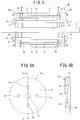
FIG. 5 is a sectional view illustrating a rotor of a permanent magnet-type rotary electric machine according to a third embodiment of the present invention; -
FIG. 6 is a view illustrating an end plate constituting the rotor of the permanent magnet-type rotary electric machine according to the third embodiment of the present invention; -
FIG. 7 is a sectional view illustrating a rotor of a permanent magnet-type rotary electric machine according to a fourth embodiment of the present invention; -
FIG. 8 is a sectional view illustrating a rotor of a permanent magnet-type rotary electric machine according to a fifth embodiment of the present invention; -
FIG. 9 is a sectional view illustrating a rotor of a permanent magnet-type rotary electric machine according to a sixth embodiment of the present invention; -
FIG. 10 is a sectional view illustrating a rotor of a permanent magnet-type rotary electric machine according to a seventh embodiment of the present invention; -
FIG. 11 is a sectional view illustrating a rotor of a permanent magnet-type rotary electric machine according to an eighth embodiment of the present invention; -
FIG. 12 is an arrow view along a line XII-XII inFIG 11 ; and -
FIG. 13 is a view illustrating an end plate constituting the rotor of the permanent magnet-type rotary electric machine according to the eighth embodiment of the present invention. - The following describes an embodiment for carrying out the present invention (hereinafter referred to as "embodiment") in detail with reference to the drawings.
-
FIGS. 1 to 3 illustrate arotor 1 of a permanent magnet-type rotary electric machine according to a first embodiment. The permanent magnet-type rotary electric machine includes a stator (not illustrated), and therotor 1 placed in a rotatable manner via a gap from an inner peripheral surface of the stator. - As illustrated in
FIGS. 1 and 2 , therotor 1 includes: arotating shaft 2; arotor core 3 through which the rotatingshaft 2 penetrates so as to be fixed thereto in an integrally rotatable manner; a plurality ofrotor slots 4 provided at regular intervals in a circumferential direction of an inside of therotor core 3 and formed to penetrate therethrough in an axial direction; a plurality ofpermanent magnets 5 inserted into therotor slots 4; a pair ofend plates rotor core 3; a plurality ofclamping bolts 7 placed to penetrate through therotor core 3 and the pair ofend plates nuts 8 screwed onto threadedportions 7a at tips ofrespective clamping bolts 7. Note that an adhesive (not illustrated) is applied to an inner surface of therotor slot 4, so that thepermanent magnet 5 inserted into therotor slot 4 is fixed to the inner surface of therotor slot 4 via the adhesive. - The
rotor core 3 is configured by a plurality ofelectromagnetic steel sheets 3a. As illustrated inFIG. 2 , each of theelectromagnetic steel sheets 3 a has the plurality ofrotor slots 4, a shaft throughhole 3b through which therotating shaft 2 penetrates, and bolt throughholes 3c through which the plurality ofclamping bolts 7 penetrates. The plurality ofelectromagnetic steel sheets 3a is laminated in a plate-thickness direction, and the shaft throughholes 3b of theelectromagnetic steel sheets 3 a thus laminated are shrink-fitted to the rotatingshaft 2, so that therotor core 3 is fixed to the rotatingshaft 2 in an integrally rotatable manner therewith. - Further, as illustrated in
FIGS. 3A, 3B , oneend plate 6a out of the pair ofend plates flat portion 9 having generally the same outer shape as theelectromagnetic steel sheets 3a constituting therotor core 3; and anannular protruding portion 10 projecting from an outer edge of the circularflat portion 9 in a direction perpendicular to a plane of the circularflat portion 9. In the circularflat portion 9, a shaft throughhole 11 through which therotating shaft 2 penetrates is formed in a central part thereof, and a plurality of bolt throughholes 12 through which theclamping bolts 7 penetrate is formed around the shaft throughhole 11. Further, theother end plate 6b out of the pair ofend plates end plate 6a illustrated inFIGS. 3A, 3B . - Here, a pressing portion of the present invention corresponds to the
annular protruding portion 10. - As illustrated in
FIG. 1 , theclamping bolts 7 are passed through the bolt throughholes 12 of the pair ofend plates rotor core 3 and the bolt throughholes 3c of therotor core 3, and thenuts 8 are screwed onto the threadedportions 7a of theclamping bolts 7 to fasten the pair ofend plates portions 10 of the pair ofend plates electromagnetic steel sheets 3a at both ends of therotor core 3, to sandwich and press an outer peripheral side of therotor core 3 toward an inner side in the axial direction. - According to the
rotor 1 of the permanent magnet-type rotary electric machine according to the first embodiment, the annular protrudingportions 10 of the pair ofend plates rotor core 3 abut with outer peripheries of theelectromagnetic steel sheets 3 a at both ends of therotor core 3. By fastening the pair ofend plates clamping bolts 7 and thenuts 8, the annular protrudingportions 10 of the pair ofend plates rotor core 3 toward the inner side in the axial direction. As such, even when plate thicknesses of the laminatedelectromagnetic steel sheets 3 a are uneven, it is possible to surely eliminate a space on the outer peripheral side of theelectromagnetic steel sheets 3a and to prevent a decrease of a magnetic characteristic of therotor 1. - Next will be described rotors of permanent magnet-type rotary electric machines according to second to eighth embodiments. Note that a part having the same configuration as the first embodiment has the same reference sign, and a description thereof is omitted.
- Subsequently,
FIG. 4 illustrates arotor 20 of a permanent magnet-type rotary electric machine according to the second embodiment in which some members have different configurations from therotor 1 of the permanent magnet-type rotary electric machine according to the first embodiment. - In the
rotor 20 of the second embodiment, adiscoid end plate 21 is placed at one axial end of arotor core 3. Thediscoid end plate 21 has generally the same outer shape aselectromagnetic steel sheets 3a constituting therotor core 3, and a shaft throughhole 22 through which a rotatingshaft 2 penetrates, and a plurality of bolt throughholes 23 through which clampingbolts 7 penetrate are formed. Further, anend plate 6b having the same structure as the first embodiment is placed at the other axial end of therotor core 3. - The clamping
bolts 7 are passed through the bolt throughholes end plates rotor core 3 and bolt throughholes 3c of therotor core 3, andnuts 8 are screwed onto threadedportions 7a of the clampingbolts 7 to fasten theend plates portion 10 of the end plate 66b abuts with an outer periphery of theelectromagnetic steel sheet 3a at the other end of therotor core 3, so that the annular protrudingportion 10 and an outer peripheral side of theend plate 6b sandwich and press therotor core 3 toward an inner side in the axial direction. - Accordingly, similarly to the
rotor 1 of the first embodiment, even when plate thicknesses of the laminatedelectromagnetic steel sheets 3 a are uneven, therotor 20 of the second embodiment can surely eliminate a space on an outer peripheral side of theelectromagnetic steel sheets 3 a and prevent a decrease of a magnetic characteristic of therotor 20. - Subsequently,
FIGS. 5 and 6 illustrate arotor 30 of a permanent magnet-type rotary electric machine according to a third embodiment. - The
rotor 30 according to the third embodiment is different from therotor 1 of the permanent magnet-type rotary electric machine according to the first embodiment in the structure of the end plates. - In the
rotor 30 of the third embodiment, a pair ofend plates rotor core 3. - As illustrated in
FIGS. 6A, 6B , oneend plate 31a out of the pair ofend plates circular plate portion 32 having generally the same outer shape withelectromagnetic steel sheets 3a constituting therotor core 3; a shaft throughhole 33 formed in a center of thecircular plate portion 32 so that arotating shaft 2 penetrates therethrough, and a plurality of bolt throughholes 34 formed around the shaft throughhole 33 so that clampingbolts 7 penetrate therethrough. - One surface, in a plate-thickness direction, of the
circular plate portion 32 which surface abuts with an end of therotor core 3 is formed as aninclined surface 35 such that its plate thickness is thickest in its outermost periphery and the plate thickness gradually decreases toward the shaft throughhole 33 from the outermost periphery. - Further, the
other end plate 31b out of the pair ofend plates end plate 31a illustrated inFIGS. 6A, 6B . - Here, the pressing portion of the present invention corresponds to the thickest outermost periphery of the
inclined surface 35. - As illustrated in
FIG. 5 , the clampingbolts 7 are passed through the bolt throughholes 34 of the pair ofend plates rotor core 3 and bolt throughholes 3c of therotor core 3, andnuts 8 are screwed onto threadedportions 7a of the clampingbolts 7 to fasten the pair ofend plates inclined surfaces 35 of the pair ofend plates electromagnetic steel sheets 3a at both ends of therotor core 3, to sandwich and press an outer peripheral side of therotor core 3 toward an inner side in the axial direction. - Thus, according to the
rotor 1 of the permanent magnet-type rotary electric machine according to the third embodiment, theinclined surfaces 35 of the pair ofend plates rotor core 3 abut with the outer peripheries of theelectromagnetic steel sheets 3 a at both ends of therotor core 3. By fastening the pair ofend plates bolts 7 and thenuts 8, theinclined surfaces 35 of the pair ofend plates rotor core 3 toward the inner side in the axial direction. As such, even when plate thicknesses of the laminatedelectromagnetic steel sheets 3a are uneven, it is possible to surely eliminate a space on the outer peripheral side of theelectromagnetic steel sheets 3 a and to prevent a decrease of a magnetic characteristic of therotor 30. - Further, the thickest parts of the
inclined surfaces 35 of the pair ofend plates electromagnetic steel sheets 3a at both ends of therotor core 3 with a small contact area, thereby making it possible to increase a pressing force to sandwich the outer peripheral side of therotor core 3 toward the inner side in the axial direction. - Subsequently,
FIG. 7 illustrates arotor 40 of a permanent magnet-type rotary electric machine according to a fourth embodiment. - The
rotor 40 according to the fourth embodiment is also different from therotor 1 of the permanent magnet-type rotary electric machine according to the first embodiment in the structure of the end plates. - In the
rotor 40 of the fourth embodiment, a pair ofend plates rotor core 3. - One
end plate 41a out of the pair ofend plates flat portion 42 having generally the same outer shape aselectromagnetic steel sheets 3a constituting therotor core 3, and an annular protrudingportion 43 projecting from an outer edge of the circularflat portion 42 in a direction perpendicular to a plane of the circularflat portion 9. A plate thickness T of the annular protrudingportion 43 is set to a plate thickness that allows the annular protrudingportion 43 to abut with an outer periphery of theelectromagnetic steel sheet 3a at an end of therotor core 3 and also to abut with part ofpermanent magnets 5 inserted intorotor slots 4. - In the circular
flat portion 42, a shaft throughhole 44 through which arotating shaft 2 penetrates is formed in a central part thereof, and a plurality of bolt throughholes 45 through which clampingbolts 7 penetrate is formed around the shaft throughhole 44. Further, theother end plate 41b out of the pair ofend plates end plate 41 a. - Here, the pressing portion of the present invention corresponds to the annular protruding
portion 43. - Then, the clamping
bolts 7 are passed through the bolt throughholes 45 of the pair ofend plates rotor core 3 and bolt throughholes 3c of therotor core 3, andnuts 8 are screwed onto threadedportions 7a of the clampingbolts 7 to fasten the pair ofend plates portions 43 of the pair ofend plates electromagnetic steel sheets 3a at both ends of therotor core 3 and thepermanent magnets 5 inserted into therotor slots 4. - Thus, according to the
rotor 40 of the permanent magnet-type rotary electric machine according to the fourth embodiment, the annular protrudingportions 43 of the pair ofend plates rotor core 3 abut with the outer peripheries of theelectromagnetic steel sheets 3a at both ends of therotor core 3. By fastening the pair ofend plates bolts 7 and thenuts 8, the annular protrudingportions 43 of the pair ofend plates rotor core 3 toward an inner side in the axial direction. As such, even when plate thicknesses of the laminatedelectromagnetic steel sheets 3a are uneven, it is possible to surely eliminate a space on the outer peripheral side of theelectromagnetic steel sheets 3a and to prevent a decrease of a magnetic characteristic of therotor 40. - In addition, the annular protruding
portions 43 of the pair ofend plates permanent magnets 5 inserted into therotor slots 4, so it is possible to further surely prevent movements of thepermanent magnets 5 in therotor slots 4 at the time when therotor 40 rotates or stops. - Subsequently,
FIG. 8 illustrates arotor 50 of a permanent magnet-type rotary electric machine according to a fifth embodiment. - The
rotor 50 according to the fifth embodiment is also different from therotor 1 of the permanent magnet-type rotary electric machine according to the first embodiment in the structure of the end plates. - In the
rotor 50 of the fifth embodiment, a pair ofend plates rotor core 3. - One
end plate 51a out of the pair ofend plates flat portion 52 having generally the same outer shape aselectromagnetic steel sheets 3a constituting therotor core 3, a first annular protrudingportion 53 projecting from an outer edge of the circularflat portion 52 in a direction perpendicular to a plane of the circularflat portion 9, and a second annular protrudingportion 54 provided projecting on the edge side of the circularflat portion 52 and on an inner side relative to the first annular protrudingportion 53. - In the circular
flat portion 52, a shaft throughhole 55 through which arotating shaft 2 penetrates is formed in a central part thereof, and a plurality of bolt throughholes 56 through which clampingbolts 7 penetrate is formed around the shaft throughhole 44. Further, theother end plate 51b out of the pair ofend plates end plate 51a. - Here, the pressing portion of the present invention corresponds to the first annular protruding
portion 53 and the second annular protrudingportion 54. - Then, the clamping
bolts 7 are passed through the bolt throughholes 56 of the pair ofend plates rotor core 3 and the bolt throughholes 3c of therotor core 3, andnuts 8 are screwed onto threadedportions 7a of the clampingbolts 7 to fasten the pair ofend plates portions 53 of the pair ofend plates electromagnetic steel sheets 3a at both ends of therotor core 3, and the second annular protrudingportions 54 of the pair ofend plates permanent magnets 5 inserted intorotor slots 4. - Thus, according to the
rotor 50 of the permanent magnet-type rotary electric machine according to the fifth embodiment, the first annular protrudingportions 53 of the pair ofend plates rotor core 3 abut with the outer peripheries of theelectromagnetic steel sheets 3 a at both ends of therotor core 3. By fastening the pair ofend plates bolts 7 and thenuts 8, the first annular protrudingportions 53 of the pair ofend plates rotor core 3 toward an inner side in the axial direction. As such, even when plate thicknesses of the laminatedelectromagnetic steel sheets 3a are uneven, it is possible to surely eliminate a space on the outer peripheral side of theelectromagnetic steel sheets 3a and to prevent a decrease of a magnetic characteristic of therotor 1. - In addition, the second annular protruding
portions 54 of the pair ofend plates permanent magnets 5 inserted into therotor slots 4, so it is possible to further surely prevent movements of thepermanent magnets 5 in therotor slots 4 at the time when therotor 50 rotates or stops. - Further, the first annular protruding
portion 53 of the pair ofend plates electromagnetic steel sheets 3a at both ends of therotor core 3 with a small contact area, thereby making it possible to increase a pressing force to sandwich the outer peripheral side of therotor core 3 toward the inner side in the axial direction. - Furthermore, the second annular protruding
portions 54 of the pair ofend plates permanent magnets 5 in therotor slots 4 with a small contact area, thereby making it possible to increase a pressing force to maintain thepermanent magnets 5. - Subsequently,
FIG. 9 illustrates arotor 60 of a permanent magnet-type rotary electric machine according to a sixth embodiment. - In the
rotor 60 of the sixth embodiment, a pair ofend plates rotor core 3. - One
end plate 61a out of the pair ofend plates flat portion 62, and an annular protrudingportion 63 projecting from an outer edge of the circularflat portion 62 in a direction perpendicular to a plane of the circularflat portion 62. The annular protrudingportion 63 is set to have a plate thickness that allows the annular protrudingportion 63 to abut with an outer periphery of theelectromagnetic steel sheet 3a at an end of therotor core 3 and also to abut with part ofpermanent magnets 5 inserted intorotor slots 4. In the circularflat portion 62, a shaft throughhole 64 through which arotating shaft 2 penetrates is formed in a central part thereof, and a plurality of bolt throughholes 65 through which clampingbolts 7 penetrate is formed around the shaft throughhole 64. - Further, the
other end plate 61b out of the pair ofend plates end plate 61 a. - Here, an outside diameter of the circular
flat portions 62 of the pair ofend plates rotor core 3, but smaller than an inner peripheral surface of a stator core (not illustrated). - Note that the pressing portion of the present invention corresponds to the annular protruding
portion 63. - According to the
rotor 60 of the permanent magnet-type rotary electric machine according to the sixth embodiment, the annular protrudingportions 63 of the pair ofend plates rotor core 3 abut with outer peripheries of theelectromagnetic steel sheets 3a at both ends of therotor core 3 and thepermanent magnets 5 inserted into therotor slots 4. By fastening the pair ofend plates bolts 7 andnuts 8, the annular protrudingportions 63 of the pair ofend plates rotor core 3 and thepermanent magnets 5 toward an inner side in the axial direction. As such, it is possible to surely eliminate a space on the outer peripheral side of theelectromagnetic steel sheets 3a to prevent a decrease of a magnetic characteristic of therotor 60, and it is also possible to surely fix thepermanent magnets 5 in therotor slots 4. - Further, in a case where the
rotor 60 is put on a floor of a storage place in which to store therotor 60 alone, the outside diameter of the circularflat portions 62 of the pair ofend plates rotor core 3. From this, it is the circularflat portions 62 of the pair ofend plates rotor core 3 from being damaged due to contact with the floor. - Subsequently,
FIG. 10 illustrates arotor 70 of a permanent magnet-type rotary electric machine according to a seventh embodiment. - In the
rotor 70 of the seventh embodiment, a pair ofend plates rotor core 3. - One
end plate 71a out of the pair ofend plates flat portion 72; and an annular protrudingportion 73 projecting from an outer edge of the circularflat portion 72 in a direction perpendicular to a plane of the circularflat portion 72. The annular protrudingportion 73 is set to have a plate thickness which allows the annular protrudingportion 73 to abut with part of anelectromagnetic steel sheet 3 a of therotor core 3, the part being placed on an outer peripheral side relative torotor slots 4, and which also allows the annular protrudingportion 73 to abut with part ofpermanent magnets 5 inserted into therotor slots 4. Further, in the circularflat portion 72, a shaft throughhole 74 through which arotating shaft 2 penetrates is formed in a central part thereof, and a plurality of bolt throughholes 75 through which clampingbolts 7 penetrate is formed around the shaft throughhole 74. - Note that the
other end plate 71 b out of the pair ofend plates end plate 71a. - Here, an outside diameter of the circular
flat portions 62 of the pair ofend plates rotor core 3, but has a magnitude that allows the circularflat portions 72 to make contact with that part of theelectromagnetic steel sheets 3a which is placed on the outer peripheral side relative to therotor slots 4 and part of thepermanent magnets 5. - Note that the pressing portion of the present invention corresponds to the annular protruding
portion 73. - According to the
rotor 70 of the permanent magnet-type rotary electric machine according to the seventh embodiment, the annular protrudingportions 73 of the pair ofend plates rotor core 3 abut with outer peripheries of theelectromagnetic steel sheets 3a at both ends of therotor core 3 and thepermanent magnets 5 inserted into therotor slots 4. By fastening the pair ofend plates bolts 7 andnuts 8, the annular protrudingportions 73 of the pair ofend plates rotor core 3 and thepermanent magnets 5 toward an inner side in the axial direction. As such, it is possible to surely eliminate a space on the outer peripheral side of theelectromagnetic steel sheets 3 a to prevent a decrease of a magnetic characteristic of therotor 70, and it is also possible to surely fix thepermanent magnets 5 in therotor slots 4. - Further, since the outside diameter of the circular
flat portions 72 of the pair ofend plates rotor core 3, in a case where therotor 70 of the sixth embodiment axially moves relative to a stator, it is possible to prevent therotor 70 from making contact with the stator. - Further, since the outside diameter of the circular
flat portions 72 of the pair ofend plates rotor core 3, in a case where refrigerant circulates between an inner peripheral surface of the stator and an outer peripheral surface of therotor 70, the pair ofend plates - Further,
FIGS. 11 to 13 illustrate arotor 80 of a permanent magnet-type rotary electric machine according to an eighth embodiment. - In the
rotor 40 of the eighth embodiment, a pair ofend plates rotor core 3. - The
rotor core 3 of the eighth embodiment is configured by a plurality ofelectromagnetic steel sheets 3 a, only a shaft throughhole 3b through which arotating shaft 2 is penetrating is formed in each of theelectromagnetic steel sheets 3 a. - As illustrated in
FIG. 13 , oneend plate 81a out of the pair ofend plates flat portion 82 having generally the same outer shape aselectromagnetic steel sheets 3a constituting therotor core 3, and an annular protrudingportion 83 projecting from an outer edge of the circularflat portion 82 in a direction perpendicular to a plane of the circularflat portion 82. A shaft through hole 84 through which therotating shaft 2 penetrates is formed in a central part of the circularflat portion 82. The annular protrudingportion 83 is set to have a plate thickness that allows the annular protrudingportion 83 to abut with an outer periphery of theelectromagnetic steel sheet 3 a at an end of therotor core 3 and also to abut with part ofpermanent magnets 5 inserted intorotor slots 4. - Further, the
other end plate 81b out of the pair ofend plates end plate 81a. - Here, the pressing portion of the present invention corresponds to the annular protruding
portion 83. - The shaft through
hole 3b of therotor core 3 obtained by laminating the plurality ofelectromagnetic steel sheets 3a in a plate-thickness direction is shrink-fitted to therotating shaft 2, and then,permanent magnets 5 are inserted intorotor slots 4 of therotor core 3. After that, the pair ofend plates rotating shaft 2 by sandwiching and pressing an outer peripheral side of therotor core 3 toward an inner side in the axial direction. Here, at the time of the shrink-fitting of the pair ofend plates permanent magnets 5 so that thepermanent magnets 5 are demagnetized. Accordingly, it is desirable to magnetize thepermanent magnets 5 after the shrink-fitting of the pair ofend plates - When the pair of
end plates rotor core 3 are shrink-fitted to therotating shaft 2, the annular protrudingportions 83 of the pair ofend plates electromagnetic steel sheets 3 a at both ends of therotor core 3 and thepermanent magnets 5 inserted into therotor slots 4. - Thus, according to the
rotor 80 of the permanent magnet-type rotary electric machine according to the eighth embodiment, the annular protrudingportions 83 of the pair ofend plates rotor core 3 abut with the outer peripheries of theelectromagnetic steel sheets 3a at both ends of therotor core 3. As such, an outer peripheral side of therotor core 3 is sandwiched and pressed toward an inner side in the axial direction. Accordingly, even when plate thicknesses of the laminatedelectromagnetic steel sheets 3a are uneven, it is possible to surely eliminate a space on the outer peripheral side of theelectromagnetic steel sheets 3a and prevent a decrease of a magnetic characteristic of therotor 80. - Further, since the annular protruding
portions 83 of the pair ofend plates permanent magnets 5 inserted into therotor slots 4, it is possible to further surely prevent movements of thepermanent magnets 5 in therotor slots 4 at the time when therotor 80 rotates or stops. - Further, only the shaft through
hole 3b penetrating through therotating shaft 2 is formed in therotor core 3 of the eighth embodiment, and further, only the shaft through hole 84 through which therotating shaft 2 penetrates is formed in the circularflat portions 82 of the pair ofend plates rotor 80 can be improved. - Note that, in the third to eighth embodiments, one end plate may be a discoid end plate that does not include a pressing portion, similarly to the second embodiment.
- As described above, the rotor of the permanent magnet-type rotary electric machine according to the present invention is useful to restrain a decrease of a magnetic characteristic.
- 1 ... rotor, 2 ... rotating shaft, 3 ... rotor core, 3a ... electromagnetic steel sheet, 3b ... shaft through hole, 3c ... bolt through hole, 4 ... rotor slot, 5 ... permanent magnet, 6a, 6b ... end plate, 7 ... clamping bolt, 7a ... threaded portion, 8 ... nut, 9 ... circular flat portion, 10 ... annular protruding portion, 11 ... shaft through hole, 12 ... bolt through hole, 20 ... rotor, 21 ... discoid end plate, 22 ... shaft through hole, 23 ... bolt through hole, 31a, 31b ... end plate, 32 ... circular plate portion, 33 ... shaft through hole, 34 ... bolt through hole, 35 ... inclined surface, 40 ... rotor, 41a, 41b ... end plate, 42 ... circular flat portion, 43 ... annular protruding portion, 44 ... shaft through hole, 45 ... bolt through hole, 50 ... rotor, 51a, 51b ... end plate, 52 ... circular flat portion, 53 ... first annular protruding portion, 54 ... second annular protruding portion, 55 ... shaft through hole, 56 ... bolt through hole, 60 ... rotor, 61a, 61b ... end plate, 62 ... circular flat portion, 63 ... annular protruding portion, 64 ... shaft through hole, 65 ... bolt through hole, 70 ... rotor, 71a, 71b ... end plate, 72 ... circular flat portion, 73 ... annular protruding portion, 74 ... shaft through hole, 75 ... bolt through hole, 80 ... rotor, 81a, 81b ... end plate, 82 ... circular flat portion, 83 ... annular protruding portion, 84 ... shaft through hole
Claims (10)
- A rotor of a permanent magnet-type rotary electric machine, the rotor including:a rotating shaft;a rotor core configured by laminating a plurality of electromagnetic steel sheets, the rotor core including the rotating shaft penetrating through the rotor core and fixed to the rotor core;a plurality of rotor slots formed to axially penetrate through the rotor core;a plurality of permanent magnets inserted into the rotor slots; anda pair of end plates placed at both axial ends of the rotor core, wherein,at least one end plate out of the pair of end plates is provided with a pressing portion configured to abut with an outer peripheral side of the rotor core to apply a pressing force to the outer peripheral side of the rotor core.
- The rotor of the permanent magnet-type rotary electric machine, according to claim 1, wherein,
the at least one end plate includes a circular flat portion through which the rotating shaft penetrates, and an annular protruding portion projecting from an outer edge of the circular flat portion in a direction perpendicular to the circular flat portion, to abut with the rotor core as the pressing portion. - The rotor of the permanent magnet-type rotary electric machine, according to claim 1, wherein,
the at least one end plate has a circular flat shape through which the rotating shaft penetrates, and is formed such that its plate thickness is thickest in its outermost periphery and the plate thickness gradually decreases toward a central part from the outermost periphery; and
the outermost periphery abuts with the rotor core as the pressing portion. - A rotor of a permanent magnet-type rotary electric machine, the rotor including:a rotating shaft;a rotor core configured by laminating a plurality of electromagnetic steel sheets, the rotor core including the rotating shaft penetrating the rotor core to rotate integrally with the rotating shaft;a plurality of rotor slots formed to axially penetrate through the rotor core;a plurality of permanent magnets inserted into the rotor slots; anda pair of end plates placed at both axial ends of the rotor core, through which the rotating shaft penetrates, wherein,at least one end plate out of the pair of end plates is provided with a pressing portion configured to abut with an outer peripheral side of the rotor core and the permanent magnets to apply a pressing force to the outer peripheral side of the rotor core and the permanent magnets.
- The rotor of the permanent magnet-type rotary electric machine, according to claim 4, wherein,
the at least one end plate includes a circular flat portion through which the rotating shaft penetrates, and an annular protruding portion projecting from an outer edge of the circular flat portion in a direction perpendicular to the circular flat portion, to abut with the rotor core and the permanent magnets as the pressing portion. - The rotor of the permanent magnet-type rotary electric machine, according to claim 5, wherein,
the annular protruding portion includes a first annular protruding portion abutting the outer peripheral side of the rotor core, and a second annular protruding portion abutting with the permanent magnets. - The rotor of the permanent magnet-type rotary electric machine, according to any one of claims 1 to 6, wherein,
an outside diameter of the end plates is set to be larger than an outside diameter of the rotor core. - The rotor of the permanent magnet-type rotary electric machine, according to any one of claims 1 to 6, wherein,
an outside diameter of the end plates is set to be smaller than an outside diameter of the rotor core. - The rotor of the permanent magnet-type rotary electric machine, according to any one of claims 1 to 6, wherein,
the pair of end plates are placed at both axial ends of the rotor core by screwing nuts onto clamping bolts provided to penetrate through through holes provided in the rotor core and the pair of end plates. - The rotor of the permanent magnet-type rotary electric machine, according to any one of claims 1 to 6, wherein,
the pair of end plates are shrink-fitted to a shaft through hole penetrating through the rotating shaft in a fixed manner to sandwich both axial ends of the rotor core.
Applications Claiming Priority (2)
| Application Number | Priority Date | Filing Date | Title |
|---|---|---|---|
| JP2014118798 | 2014-06-09 | ||
| PCT/JP2015/002402 WO2015190033A1 (en) | 2014-06-09 | 2015-05-12 | Rotor of permanent magnet-type rotary electric machine |
Publications (3)
| Publication Number | Publication Date |
|---|---|
| EP3154156A1 true EP3154156A1 (en) | 2017-04-12 |
| EP3154156A4 EP3154156A4 (en) | 2017-08-16 |
| EP3154156B1 EP3154156B1 (en) | 2021-03-10 |
Family
ID=54833151
Family Applications (1)
| Application Number | Title | Priority Date | Filing Date |
|---|---|---|---|
| EP15807567.1A Active EP3154156B1 (en) | 2014-06-09 | 2015-05-12 | Rotor of permanent magnet-type rotary electric machine |
Country Status (5)
| Country | Link |
|---|---|
| US (1) | US10284061B2 (en) |
| EP (1) | EP3154156B1 (en) |
| JP (1) | JP6443446B2 (en) |
| CN (1) | CN105518976A (en) |
| WO (1) | WO2015190033A1 (en) |
Cited By (2)
| Publication number | Priority date | Publication date | Assignee | Title |
|---|---|---|---|---|
| DE102018200865A1 (en) * | 2018-01-19 | 2019-07-25 | Continental Automotive Gmbh | Rotor for an electric machine |
| DE102022125700A1 (en) * | 2022-10-05 | 2024-04-11 | Valeo Eautomotive Germany Gmbh | Rotor for an electrical machine with improved holding elements for the axial fixation of a rotor laminated core |
Families Citing this family (13)
| Publication number | Priority date | Publication date | Assignee | Title |
|---|---|---|---|---|
| JP7059059B2 (en) * | 2018-03-15 | 2022-04-25 | 本田技研工業株式会社 | Rotating machine rotor |
| JP7059058B2 (en) * | 2018-03-15 | 2022-04-25 | 本田技研工業株式会社 | Rotating machine rotor |
| CN108448762B (en) * | 2018-05-11 | 2020-05-22 | 合肥巨一动力系统有限公司 | A motor rotor assembly structure |
| JP7293627B2 (en) * | 2018-12-05 | 2023-06-20 | 株式会社デンソー | Rotating electric machine and manufacturing method of rotating electric machine |
| JP7371361B2 (en) | 2019-06-20 | 2023-10-31 | 株式会社デンソー | rotating electric machine |
| JP7342447B2 (en) * | 2019-06-20 | 2023-09-12 | 株式会社デンソー | Rotating electric machine and manufacturing method of rotating electric machine |
| US11594925B2 (en) * | 2020-02-12 | 2023-02-28 | Toyota Jidosha Kabushiki Kaisha | Rotor of rotary electric machine for vehicle |
| CN112104180B (en) * | 2020-08-21 | 2023-05-09 | 石镇德 | Asynchronous starting permanent magnet auxiliary synchronous reluctance motor |
| FR3115949B1 (en) * | 2020-11-05 | 2025-06-20 | Valeo Equip Electr Moteur | Rotor of a rotating electrical machine |
| FR3118345B1 (en) | 2020-12-17 | 2024-08-23 | Valeo Equip Electr Moteur | Rotor of a rotating electric machine and rotating electric machine equipped with such a rotor |
| CN113726052A (en) * | 2021-09-27 | 2021-11-30 | 珠海格力电器股份有限公司 | Rotor baffle plate assembly, motor and industrial ceiling fan |
| WO2024225275A1 (en) * | 2023-04-28 | 2024-10-31 | ニデック株式会社 | Rotor, rotating electrical machine, and drive device |
| WO2025203336A1 (en) * | 2024-03-27 | 2025-10-02 | 三菱電機株式会社 | Rotor, motor, blower, air-conditioning device, and method for manufacturing rotor |
Family Cites Families (18)
| Publication number | Priority date | Publication date | Assignee | Title |
|---|---|---|---|---|
| JPS61150640A (en) * | 1984-12-25 | 1986-07-09 | Sanyo Electric Co Ltd | Permanent magnet rotor |
| JPS61199448A (en) * | 1985-02-28 | 1986-09-03 | Fanuc Ltd | Permanent magnet field rotor assembly |
| JP3757434B2 (en) * | 1994-07-20 | 2006-03-22 | ダイキン工業株式会社 | Brushless DC motor |
| JP2003259577A (en) * | 2002-03-01 | 2003-09-12 | Toyota Motor Corp | Permanent magnet type motor rotor assembly |
| US7042127B2 (en) | 2003-04-02 | 2006-05-09 | Nidec Sankyo Corporation | Permanent magnet embedded motor |
| JP2005039909A (en) * | 2003-07-17 | 2005-02-10 | Sankyo Seiki Mfg Co Ltd | Permanent magnet embedded type motor |
| JP2005102460A (en) | 2003-08-29 | 2005-04-14 | Toyota Motor Corp | Rotating electric machine rotor |
| JP2006014473A (en) * | 2004-06-25 | 2006-01-12 | Aisin Seiki Co Ltd | motor |
| DE102006022362A1 (en) * | 2006-05-12 | 2007-11-15 | Siemens Ag | Permanent magnet synchronous machine |
| JP2008178253A (en) | 2007-01-19 | 2008-07-31 | Fanuc Ltd | Method for manufacturing motor rotor and motor |
| CN202309273U (en) | 2010-07-15 | 2012-07-04 | 富士电机株式会社 | Permanent magnet type rotor of rotary motor |
| JP2012147616A (en) * | 2011-01-14 | 2012-08-02 | Aisin Seiki Co Ltd | Rotor for rotating electric machine |
| US8970085B2 (en) * | 2011-04-01 | 2015-03-03 | Denso Corporation | Rotor for electric rotating machine and method of manufacturing the same |
| JP5353939B2 (en) * | 2011-04-01 | 2013-11-27 | 株式会社デンソー | Rotating electrical machine rotor |
| JP2013099051A (en) * | 2011-10-31 | 2013-05-20 | Toyota Industries Corp | Rotor of permanent magnet rotary electric machine and permanent magnet rotary electric machine |
| JP2013138588A (en) | 2011-12-28 | 2013-07-11 | Daikin Ind Ltd | Permanent magnet rotor |
| CN102545493B (en) * | 2012-01-22 | 2014-03-05 | 浙江大学 | Method for manufacturing rotor of permanent-magnet motor |
| JP2014087103A (en) * | 2012-10-19 | 2014-05-12 | Toyota Industries Corp | Rotor of magnet-embedded rotary electric machine |
-
2015
- 2015-05-12 US US14/917,735 patent/US10284061B2/en active Active
- 2015-05-12 WO PCT/JP2015/002402 patent/WO2015190033A1/en not_active Ceased
- 2015-05-12 CN CN201580001810.1A patent/CN105518976A/en active Pending
- 2015-05-12 EP EP15807567.1A patent/EP3154156B1/en active Active
- 2015-05-12 JP JP2016527618A patent/JP6443446B2/en active Active
Cited By (3)
| Publication number | Priority date | Publication date | Assignee | Title |
|---|---|---|---|---|
| DE102018200865A1 (en) * | 2018-01-19 | 2019-07-25 | Continental Automotive Gmbh | Rotor for an electric machine |
| DE102018200865B4 (en) | 2018-01-19 | 2023-10-05 | Vitesco Technologies GmbH | Rotor for an electric machine |
| DE102022125700A1 (en) * | 2022-10-05 | 2024-04-11 | Valeo Eautomotive Germany Gmbh | Rotor for an electrical machine with improved holding elements for the axial fixation of a rotor laminated core |
Also Published As
| Publication number | Publication date |
|---|---|
| US10284061B2 (en) | 2019-05-07 |
| CN105518976A (en) | 2016-04-20 |
| JP6443446B2 (en) | 2018-12-26 |
| WO2015190033A1 (en) | 2015-12-17 |
| US20170085160A1 (en) | 2017-03-23 |
| EP3154156B1 (en) | 2021-03-10 |
| EP3154156A4 (en) | 2017-08-16 |
| JPWO2015190033A1 (en) | 2017-04-20 |
Similar Documents
| Publication | Publication Date | Title |
|---|---|---|
| EP3154156B1 (en) | Rotor of permanent magnet-type rotary electric machine | |
| CN113169594B (en) | Laminated iron core and rotating electrical machine | |
| US20160315526A1 (en) | Rotary electric machine rotor | |
| US9190878B2 (en) | Rotor including anti-rotation feature for multi-pole structure | |
| JP2015100227A (en) | Rotary electric machine rotor | |
| US9621001B2 (en) | Rotor assembly for electric machine having mechanical retention system for magnets | |
| US20140062245A1 (en) | Rotor for rotating electric machine | |
| US10439455B2 (en) | Method for manufacturing strator, method for manufacturing rotary electric machine, and iron-core block | |
| WO2014046101A1 (en) | Stator fixing structure | |
| CN103378701A (en) | Rotor for a motor and a motor | |
| EP2955816B1 (en) | Embedded permanent magnet type rotating electric machine | |
| JP2015163006A (en) | Rotating electric machine and manufacturing method thereof | |
| US20120181894A1 (en) | Rotor for rotary electric machine | |
| JP2021087242A (en) | Rotor equipped with end plate disposed on end surface of rotor core, and electric motor equipped with rotor | |
| CN202309273U (en) | Permanent magnet type rotor of rotary motor | |
| US10411537B2 (en) | Rotor lamination and related rotor and electric motor incorporating same | |
| JP2015204680A (en) | Rotating electric machine rotor and rotating electric machine equipped with the same | |
| JP2018007530A (en) | Method for manufacturing rotor core | |
| JP2012253884A (en) | Rotor, rotary electric machine, and method for manufacturing rotor | |
| JP5899683B2 (en) | Rotor and rotating electric machine equipped with rotor | |
| JP6032178B2 (en) | Induction motor rotor | |
| JP2013135598A (en) | Rotor for rotating electric machine | |
| US12374944B2 (en) | Rotor for a rotating electric machine including end plates and fixing portions | |
| JP6165622B2 (en) | Rotating electric machine rotor and rotating electric machine equipped with the same | |
| CN110720169B (en) | Rotor structure of motor |
Legal Events
| Date | Code | Title | Description |
|---|---|---|---|
| STAA | Information on the status of an ep patent application or granted ep patent |
Free format text: STATUS: THE INTERNATIONAL PUBLICATION HAS BEEN MADE |
|
| PUAI | Public reference made under article 153(3) epc to a published international application that has entered the european phase |
Free format text: ORIGINAL CODE: 0009012 |
|
| STAA | Information on the status of an ep patent application or granted ep patent |
Free format text: STATUS: REQUEST FOR EXAMINATION WAS MADE |
|
| 17P | Request for examination filed |
Effective date: 20160309 |
|
| AK | Designated contracting states |
Kind code of ref document: A1 Designated state(s): AL AT BE BG CH CY CZ DE DK EE ES FI FR GB GR HR HU IE IS IT LI LT LU LV MC MK MT NL NO PL PT RO RS SE SI SK SM TR |
|
| AX | Request for extension of the european patent |
Extension state: BA ME |
|
| A4 | Supplementary search report drawn up and despatched |
Effective date: 20170713 |
|
| RIC1 | Information provided on ipc code assigned before grant |
Ipc: H02K 1/27 20060101AFI20170707BHEP |
|
| DAV | Request for validation of the european patent (deleted) | ||
| DAX | Request for extension of the european patent (deleted) | ||
| STAA | Information on the status of an ep patent application or granted ep patent |
Free format text: STATUS: EXAMINATION IS IN PROGRESS |
|
| 17Q | First examination report despatched |
Effective date: 20200205 |
|
| GRAP | Despatch of communication of intention to grant a patent |
Free format text: ORIGINAL CODE: EPIDOSNIGR1 |
|
| STAA | Information on the status of an ep patent application or granted ep patent |
Free format text: STATUS: GRANT OF PATENT IS INTENDED |
|
| INTG | Intention to grant announced |
Effective date: 20200929 |
|
| GRAS | Grant fee paid |
Free format text: ORIGINAL CODE: EPIDOSNIGR3 |
|
| GRAA | (expected) grant |
Free format text: ORIGINAL CODE: 0009210 |
|
| STAA | Information on the status of an ep patent application or granted ep patent |
Free format text: STATUS: THE PATENT HAS BEEN GRANTED |
|
| AK | Designated contracting states |
Kind code of ref document: B1 Designated state(s): AL AT BE BG CH CY CZ DE DK EE ES FI FR GB GR HR HU IE IS IT LI LT LU LV MC MK MT NL NO PL PT RO RS SE SI SK SM TR |
|
| REG | Reference to a national code |
Ref country code: GB Ref legal event code: FG4D |
|
| REG | Reference to a national code |
Ref country code: AT Ref legal event code: REF Ref document number: 1370894 Country of ref document: AT Kind code of ref document: T Effective date: 20210315 Ref country code: CH Ref legal event code: EP |
|
| REG | Reference to a national code |
Ref country code: DE Ref legal event code: R096 Ref document number: 602015066744 Country of ref document: DE |
|
| REG | Reference to a national code |
Ref country code: IE Ref legal event code: FG4D |
|
| REG | Reference to a national code |
Ref country code: LT Ref legal event code: MG9D |
|
| PG25 | Lapsed in a contracting state [announced via postgrant information from national office to epo] |
Ref country code: LT Free format text: LAPSE BECAUSE OF FAILURE TO SUBMIT A TRANSLATION OF THE DESCRIPTION OR TO PAY THE FEE WITHIN THE PRESCRIBED TIME-LIMIT Effective date: 20210310 Ref country code: NO Free format text: LAPSE BECAUSE OF FAILURE TO SUBMIT A TRANSLATION OF THE DESCRIPTION OR TO PAY THE FEE WITHIN THE PRESCRIBED TIME-LIMIT Effective date: 20210610 Ref country code: BG Free format text: LAPSE BECAUSE OF FAILURE TO SUBMIT A TRANSLATION OF THE DESCRIPTION OR TO PAY THE FEE WITHIN THE PRESCRIBED TIME-LIMIT Effective date: 20210610 Ref country code: FI Free format text: LAPSE BECAUSE OF FAILURE TO SUBMIT A TRANSLATION OF THE DESCRIPTION OR TO PAY THE FEE WITHIN THE PRESCRIBED TIME-LIMIT Effective date: 20210310 Ref country code: GR Free format text: LAPSE BECAUSE OF FAILURE TO SUBMIT A TRANSLATION OF THE DESCRIPTION OR TO PAY THE FEE WITHIN THE PRESCRIBED TIME-LIMIT Effective date: 20210611 Ref country code: HR Free format text: LAPSE BECAUSE OF FAILURE TO SUBMIT A TRANSLATION OF THE DESCRIPTION OR TO PAY THE FEE WITHIN THE PRESCRIBED TIME-LIMIT Effective date: 20210310 |
|
| REG | Reference to a national code |
Ref country code: AT Ref legal event code: MK05 Ref document number: 1370894 Country of ref document: AT Kind code of ref document: T Effective date: 20210310 |
|
| REG | Reference to a national code |
Ref country code: NL Ref legal event code: MP Effective date: 20210310 |
|
| PG25 | Lapsed in a contracting state [announced via postgrant information from national office to epo] |
Ref country code: SE Free format text: LAPSE BECAUSE OF FAILURE TO SUBMIT A TRANSLATION OF THE DESCRIPTION OR TO PAY THE FEE WITHIN THE PRESCRIBED TIME-LIMIT Effective date: 20210310 Ref country code: LV Free format text: LAPSE BECAUSE OF FAILURE TO SUBMIT A TRANSLATION OF THE DESCRIPTION OR TO PAY THE FEE WITHIN THE PRESCRIBED TIME-LIMIT Effective date: 20210310 Ref country code: RS Free format text: LAPSE BECAUSE OF FAILURE TO SUBMIT A TRANSLATION OF THE DESCRIPTION OR TO PAY THE FEE WITHIN THE PRESCRIBED TIME-LIMIT Effective date: 20210310 |
|
| PG25 | Lapsed in a contracting state [announced via postgrant information from national office to epo] |
Ref country code: NL Free format text: LAPSE BECAUSE OF FAILURE TO SUBMIT A TRANSLATION OF THE DESCRIPTION OR TO PAY THE FEE WITHIN THE PRESCRIBED TIME-LIMIT Effective date: 20210310 |
|
| PG25 | Lapsed in a contracting state [announced via postgrant information from national office to epo] |
Ref country code: CZ Free format text: LAPSE BECAUSE OF FAILURE TO SUBMIT A TRANSLATION OF THE DESCRIPTION OR TO PAY THE FEE WITHIN THE PRESCRIBED TIME-LIMIT Effective date: 20210310 Ref country code: EE Free format text: LAPSE BECAUSE OF FAILURE TO SUBMIT A TRANSLATION OF THE DESCRIPTION OR TO PAY THE FEE WITHIN THE PRESCRIBED TIME-LIMIT Effective date: 20210310 Ref country code: SM Free format text: LAPSE BECAUSE OF FAILURE TO SUBMIT A TRANSLATION OF THE DESCRIPTION OR TO PAY THE FEE WITHIN THE PRESCRIBED TIME-LIMIT Effective date: 20210310 Ref country code: AT Free format text: LAPSE BECAUSE OF FAILURE TO SUBMIT A TRANSLATION OF THE DESCRIPTION OR TO PAY THE FEE WITHIN THE PRESCRIBED TIME-LIMIT Effective date: 20210310 |
|
| PG25 | Lapsed in a contracting state [announced via postgrant information from national office to epo] |
Ref country code: IS Free format text: LAPSE BECAUSE OF FAILURE TO SUBMIT A TRANSLATION OF THE DESCRIPTION OR TO PAY THE FEE WITHIN THE PRESCRIBED TIME-LIMIT Effective date: 20210710 Ref country code: RO Free format text: LAPSE BECAUSE OF FAILURE TO SUBMIT A TRANSLATION OF THE DESCRIPTION OR TO PAY THE FEE WITHIN THE PRESCRIBED TIME-LIMIT Effective date: 20210310 Ref country code: SK Free format text: LAPSE BECAUSE OF FAILURE TO SUBMIT A TRANSLATION OF THE DESCRIPTION OR TO PAY THE FEE WITHIN THE PRESCRIBED TIME-LIMIT Effective date: 20210310 Ref country code: PT Free format text: LAPSE BECAUSE OF FAILURE TO SUBMIT A TRANSLATION OF THE DESCRIPTION OR TO PAY THE FEE WITHIN THE PRESCRIBED TIME-LIMIT Effective date: 20210712 Ref country code: PL Free format text: LAPSE BECAUSE OF FAILURE TO SUBMIT A TRANSLATION OF THE DESCRIPTION OR TO PAY THE FEE WITHIN THE PRESCRIBED TIME-LIMIT Effective date: 20210310 Ref country code: ES Free format text: LAPSE BECAUSE OF FAILURE TO SUBMIT A TRANSLATION OF THE DESCRIPTION OR TO PAY THE FEE WITHIN THE PRESCRIBED TIME-LIMIT Effective date: 20210310 |
|
| REG | Reference to a national code |
Ref country code: DE Ref legal event code: R097 Ref document number: 602015066744 Country of ref document: DE |
|
| REG | Reference to a national code |
Ref country code: CH Ref legal event code: PL |
|
| PLBE | No opposition filed within time limit |
Free format text: ORIGINAL CODE: 0009261 |
|
| STAA | Information on the status of an ep patent application or granted ep patent |
Free format text: STATUS: NO OPPOSITION FILED WITHIN TIME LIMIT |
|
| PG25 | Lapsed in a contracting state [announced via postgrant information from national office to epo] |
Ref country code: DK Free format text: LAPSE BECAUSE OF FAILURE TO SUBMIT A TRANSLATION OF THE DESCRIPTION OR TO PAY THE FEE WITHIN THE PRESCRIBED TIME-LIMIT Effective date: 20210310 Ref country code: CH Free format text: LAPSE BECAUSE OF NON-PAYMENT OF DUE FEES Effective date: 20210531 Ref country code: AL Free format text: LAPSE BECAUSE OF FAILURE TO SUBMIT A TRANSLATION OF THE DESCRIPTION OR TO PAY THE FEE WITHIN THE PRESCRIBED TIME-LIMIT Effective date: 20210310 Ref country code: LU Free format text: LAPSE BECAUSE OF NON-PAYMENT OF DUE FEES Effective date: 20210512 Ref country code: LI Free format text: LAPSE BECAUSE OF NON-PAYMENT OF DUE FEES Effective date: 20210531 Ref country code: MC Free format text: LAPSE BECAUSE OF FAILURE TO SUBMIT A TRANSLATION OF THE DESCRIPTION OR TO PAY THE FEE WITHIN THE PRESCRIBED TIME-LIMIT Effective date: 20210310 |
|
| REG | Reference to a national code |
Ref country code: BE Ref legal event code: MM Effective date: 20210531 |
|
| 26N | No opposition filed |
Effective date: 20211213 |
|
| PG25 | Lapsed in a contracting state [announced via postgrant information from national office to epo] |
Ref country code: SI Free format text: LAPSE BECAUSE OF FAILURE TO SUBMIT A TRANSLATION OF THE DESCRIPTION OR TO PAY THE FEE WITHIN THE PRESCRIBED TIME-LIMIT Effective date: 20210310 |
|
| PG25 | Lapsed in a contracting state [announced via postgrant information from national office to epo] |
Ref country code: IT Free format text: LAPSE BECAUSE OF FAILURE TO SUBMIT A TRANSLATION OF THE DESCRIPTION OR TO PAY THE FEE WITHIN THE PRESCRIBED TIME-LIMIT Effective date: 20210310 Ref country code: IE Free format text: LAPSE BECAUSE OF NON-PAYMENT OF DUE FEES Effective date: 20210512 |
|
| PG25 | Lapsed in a contracting state [announced via postgrant information from national office to epo] |
Ref country code: IS Free format text: LAPSE BECAUSE OF FAILURE TO SUBMIT A TRANSLATION OF THE DESCRIPTION OR TO PAY THE FEE WITHIN THE PRESCRIBED TIME-LIMIT Effective date: 20210710 |
|
| PG25 | Lapsed in a contracting state [announced via postgrant information from national office to epo] |
Ref country code: BE Free format text: LAPSE BECAUSE OF NON-PAYMENT OF DUE FEES Effective date: 20210531 |
|
| REG | Reference to a national code |
Ref country code: FR Ref legal event code: PLFP Year of fee payment: 9 |
|
| PG25 | Lapsed in a contracting state [announced via postgrant information from national office to epo] |
Ref country code: HU Free format text: LAPSE BECAUSE OF FAILURE TO SUBMIT A TRANSLATION OF THE DESCRIPTION OR TO PAY THE FEE WITHIN THE PRESCRIBED TIME-LIMIT; INVALID AB INITIO Effective date: 20150512 |
|
| PG25 | Lapsed in a contracting state [announced via postgrant information from national office to epo] |
Ref country code: CY Free format text: LAPSE BECAUSE OF FAILURE TO SUBMIT A TRANSLATION OF THE DESCRIPTION OR TO PAY THE FEE WITHIN THE PRESCRIBED TIME-LIMIT Effective date: 20210310 |
|
| PG25 | Lapsed in a contracting state [announced via postgrant information from national office to epo] |
Ref country code: MK Free format text: LAPSE BECAUSE OF FAILURE TO SUBMIT A TRANSLATION OF THE DESCRIPTION OR TO PAY THE FEE WITHIN THE PRESCRIBED TIME-LIMIT Effective date: 20210310 |
|
| PG25 | Lapsed in a contracting state [announced via postgrant information from national office to epo] |
Ref country code: TR Free format text: LAPSE BECAUSE OF FAILURE TO SUBMIT A TRANSLATION OF THE DESCRIPTION OR TO PAY THE FEE WITHIN THE PRESCRIBED TIME-LIMIT Effective date: 20210310 |
|
| PG25 | Lapsed in a contracting state [announced via postgrant information from national office to epo] |
Ref country code: MT Free format text: LAPSE BECAUSE OF FAILURE TO SUBMIT A TRANSLATION OF THE DESCRIPTION OR TO PAY THE FEE WITHIN THE PRESCRIBED TIME-LIMIT Effective date: 20210310 |
|
| PGFP | Annual fee paid to national office [announced via postgrant information from national office to epo] |
Ref country code: GB Payment date: 20250327 Year of fee payment: 11 |
|
| PGFP | Annual fee paid to national office [announced via postgrant information from national office to epo] |
Ref country code: DE Payment date: 20250402 Year of fee payment: 11 |
|
| PGFP | Annual fee paid to national office [announced via postgrant information from national office to epo] |
Ref country code: FR Payment date: 20250401 Year of fee payment: 11 |